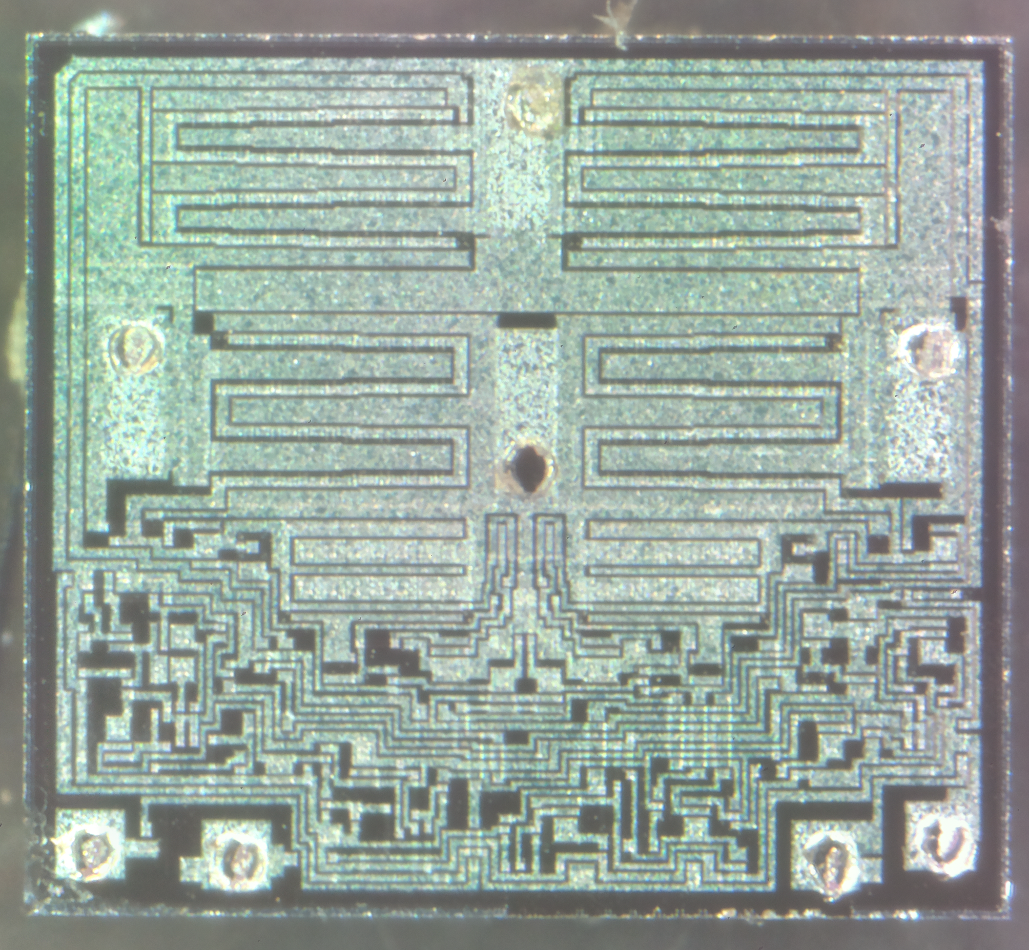
Here’s a jellybean chip – a DC motor driver. This device has all the logic to drive a small motor, such as that used to drive the tray of a CD drive in both directions. The control logic is at the bottom of the die, while the main power transistors are at the top, in H-Bridge formation.
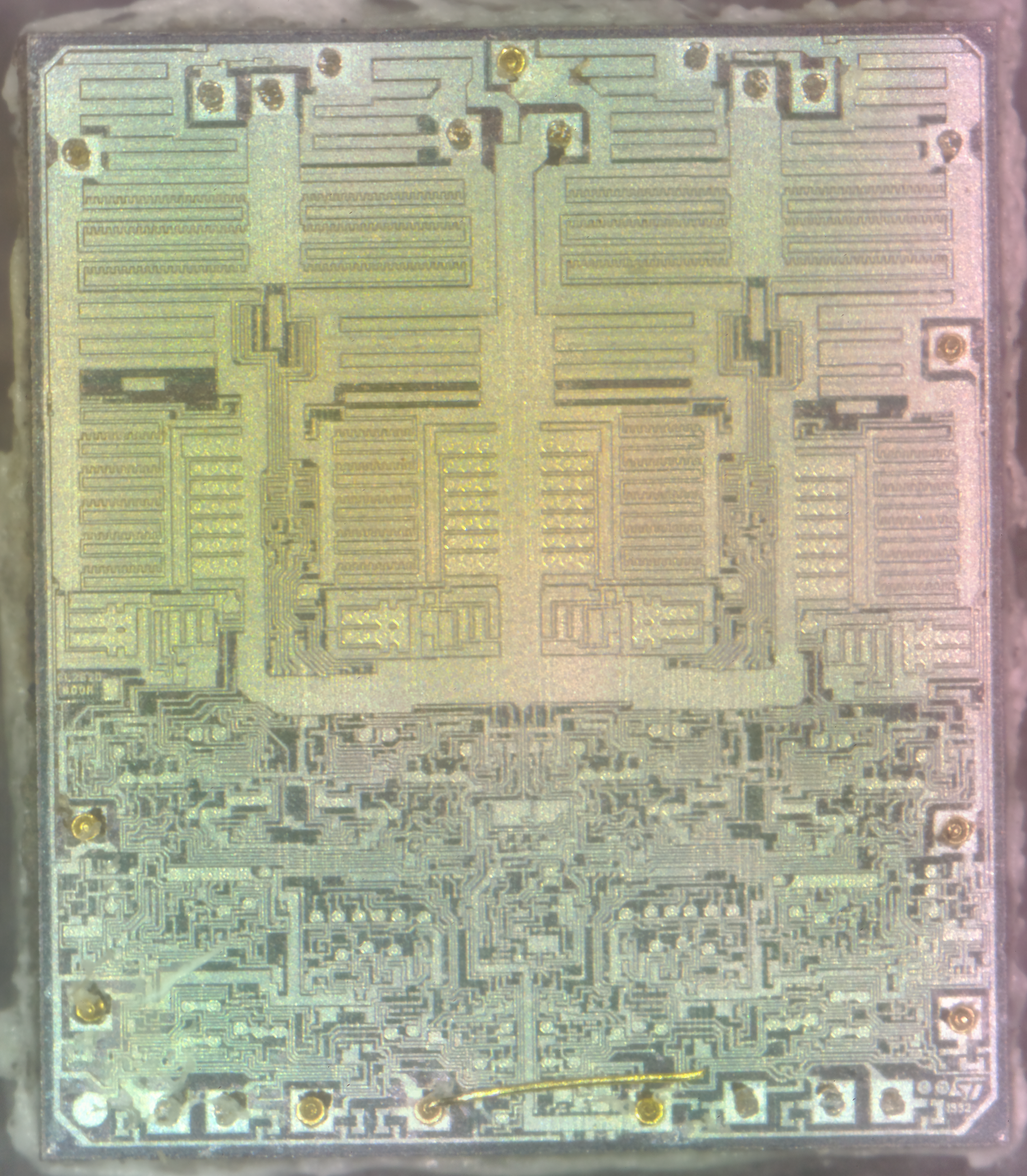
Another decapped IC! This one is an ST L6219 750mA stepper motor driver. The control logic is all at the bottom of the die, with the high current H-Bridge transistors at the top.
Time foe some more retro tech! This is a 1980’s vintage CCD-based VHS camcorder from Panasonic, the NV-M5. There are a lot of parts to one of these (unlike modern cameras), so I’ll split this post into several sections to make things easier to read (and easier to keep track of what I’m talking about :)).
Left Side
The left side of the camera holds the autofocus, white balance, shutter speed & date controls.
Left Side ControlsLens Adjustments
The lens is fully adjustable, with either manual or motorized automatic control.
Rear Panel
The back panel has the battery slot, a very strange looking DC input connector, remote control connector & the earphone jack.
Top Controls
The top panel of the camera holds the main power controls, manual tape tracking & the tape transport control panel.
Viewfinder
The viewfinder is mounted on a swivel mount. There’s a CRT based composite monitor in here. Hack ahoy!
Camera Section
Process Board Assembly
Here’s the camera section of the camcorder, and is totally packed with electronics! There’s at least half a dozen separate boards in here, all fitted together around the optics tube assembly.
AWB PCB
On the top of the assembly is the Automatic White Balance PCB. Many adjustments here to get everything set right. Not much on the other side of this board other than a bunch of Op-Amps. The iris stepper motor is fitted in a milled opening in the PCB, this connects to one of the other PCBs in the camera module.
AWB Sensor
Here’s the AWB sensor, mounted next to the lens. I’m not all to certain how this works, but the service manual has the pinout, and there are outputs for all the colour channels, RGB. So it’s probably a trio of photodiodes with filters.
Focus & Zoom Motors
Focus & Zoom are controlled with a pair of DC gear motors. The manual operation is feasible through the use of slip clutches in the final drive pinion onto the lens barrel.
Process Board
The main camera section process board is above. This board does all the signal processing for the CCD, has the bias voltage supplies and houses the control sections for the motorized parts of the optics assembly. There are quite a few dipped Tantalum capacitors on pigtails, instead of being directly board mounted. This was probably done due to space requirements on the PCB itself.
Under the steel shield on this board is some of the main signal processing for the CCD.
Optics Assembly
The back of the optics tube is a heavy casting, to supress vibration. This will be more clear later on.
Position Sensor Flex
The position of the lens elements is determined by reflective strips on the barrel & sensors on this flex PCB.
Sub Process Board
There’s another small board tucked into the side of the tube, this hooks into the process PCB.
Process Delay Line
According to the schematic, there’s nothing much on this board, just a delay line & a few transistors.
Piezo Focus Disc
Here’s the reason for the heavy alloy casing at the CCD mounting end of the optics: the fine focus adjustment is done with a piezoelectric disc, the entire CCD assembly is mounted to this board. Applying voltage to the electrodes moves the assembly slightly to alter the position of the CCD. The blue glass in the centre of the unit is the IR filter.
IR Relective Sensors
The barrel position sensors are these IR-reflective type.
Iris Assembly
The iris is mounted just before the CCD, this is controlled with a galvanometer-type device with position sensors incorporated.
Iris Opening
Pushing on the operating lever with the end of my screwdriver opens the leaves of the iris against the return spring.
Tape Transport & Main Control
Main Control Board
Tucked into the side of the main body of the unit is the main system control board. This PCB houses all the vital functions of the camera: Power Supply, Servo Control, Colour Control,Video Amplifiers, etc.
Tape Drum
Here’s the main tape transport mechanism, this is made of steel & aluminium stampings for structural support. The drum used in this transport is noticeably smaller than a standard VHS drum, the tape is wrapped around more of the drum surface to compensate.
Tape Transport
The VHS tape sits in this carriage & the spools drive the supply & take up reels in the cartridge.
Main Control PCB
Here’s the component side of the main control PCB. This one is very densely packed with parts, I wouldn’t like to try & troubleshoot something like this!
Main PCB Left
The left side has the video head amp at the top, a Panasonic AN3311K 4-head video amp. Below that is video processing, the blue components are the analogue delay lines. There are a couple of hybrid flat-flex PCBs tucked in between with a couple of ICs & many passives. These hybrids handle the luma & chroma signals.
Top left is the capstan motor driver a Rohm BA6430S. The transport motors are all 3-phase brushless, with exception of the loading motor, which is a brushed DC type.
Delay Line
Here’s what is inside the delay lines for the analogue video circuits. The plastic casing holds a felt liner, inside which is the delay line itself.
Internal Glass
The delay is created by sending an acoustic signal through the quartz crystal inside the device by a piezoelectric transducer, bouncing it off the walls of the crystal before returning it to a similar transducer.
Main PCB Centre
Here’s the centre of the board, the strange crystal at bottom centre is the clock crystal for the head drum servo. Why it has 3 pins I’m not sure, only the two pins to the crystal inside are shown connected on the schematic. Maybe grounding the case?
The main servo controls for the head drum & the capstan motor are top centre, these get a control signal from the tape to lock the speed of the relative components.
Main PCB Right
Here’s the right hand side. The main power supply circuitry is at top right, with a large can containing 4 switching inductors & a ferrite pot core transformer. All these converters are controlled by a single BA6149 6-channel DC-DC converter controller IC via a ULN2003 transistor array.
The ceramic hybrid board next to the PSU has 7 switch transistors for driving various indicator LEDs.
The large tabbed IC bottom centre is the loading motor drive, an IC from Mitsubishi, the M54543. This has bidirectional DC control of the motor & built in braking functions. The large quad flat pack IC on the right is the MN1237A on-screen character generator, with the two clock crystals for the main microcontroller.
Erase Head
The full erase head has it’s power supply & oscillator on board, applying 9v to this board results in an AC signal to the head, which erases the old recording from the tape before the new recording is laid down by the flying heads on the drum.
Audio Control PCB
The Audio & Control head is connected to this PCB, which handles both reading back audio from the tape & recording new audio tracks. The audio bias oscillator is on this board, & the onboard microphone feeds it’s signal here. The control head is fed directly through to the servo section of the main board.
Drum Motor
The motor that drives the head drum is another DC brushless 3-phase type.
Hall Sensors
These 3 Hall sensors are used by the motor drive to determine the rotor position & time commutation accordingly.
Stator
The stator on this motor is of interesting construction, with no laminated core, the coils are moulded into the plastic holder. The tach sensor is on the side of the stator core. This senses a small magnet on the outside of the rotor to determine rotational speed. For PAL recordings, the drum rotates at 1500 RPM.
Motor Removed
Not much under the stator other than the bearing housing & the feedthrough to the rotary transformer.
Head Disc
The heads are mounted onto the top disc of the drum, 4 heads in this recorder. The signals are transmitted to the rotating section through the ferrite rotary transformer on the bottom section.
Head Chip
The tiny winding of the ferrite video head can just about be seen on the end of the brass mounting.
Capstan Motor Components
The capstan motor is similar to the drum motor, only this one is flat. The rotor has a ferrite magnet, in this case it wasn’t glued in place, just held by it’s magnetic field.
Capstan Motor Stator
The PCB on this motor has a steel backing to complete the magnetic circuit, the coils for the 3 motor phases are simply glued in place. The Hall sensors on this motor are placed in the middle of the windings though.
Again there is a tach sensor on the edge of the board that communicates the speed back to the controller. This allows the servo to remain locked at constant speed.
Viewfinder
Viewfinder Assembly
As usual with these cameras, this section is the CRT based viewfinder. These units take the composite signal from the camera to display the scene. This one has many more pins than the usual viewfinder. I’ll hack a manual input into this, but I’ll leave that for another post.
Viewfinder Circuits
Being an older camera than the ones I’ve had before, this one is on a pair of PCBs, which are both single-sided.
Main Viewfinder Board
The main board has all the power components for driving the CRT & some of the adjustments. The main HV flyback transformer is on the right. This part creates both the final anode voltage for the tube & the focus/grid voltages.
Viewfinder Control PCB Top
The viewfinder control IC is on a separate daughter board in this camera, with two more controls.
Control IC
The control IC is a Matsushita AN2510S, this has all the logic required to separate the sync pulses from the composite signal & generate an image on the CRT.
Viewfinder CRT Frame
The recording indicator LEDs are mounted in the frame of the CRT & appear above the image in the viewfinder.
Viewfinder CRT With Yoke
Here the CRT has been separated from the rest of the circuitry with just the deflection yoke still attached.
M01JPG5WB CRT
The electron gun in this viewfinder CRT is massive in comparison to the others that I have seen, and the neck of the tube is also much wider. These old tubes were very well manufactured.
Viewfinder Optics
A simple mirror & magnifying lens completes the viewfinder unit.
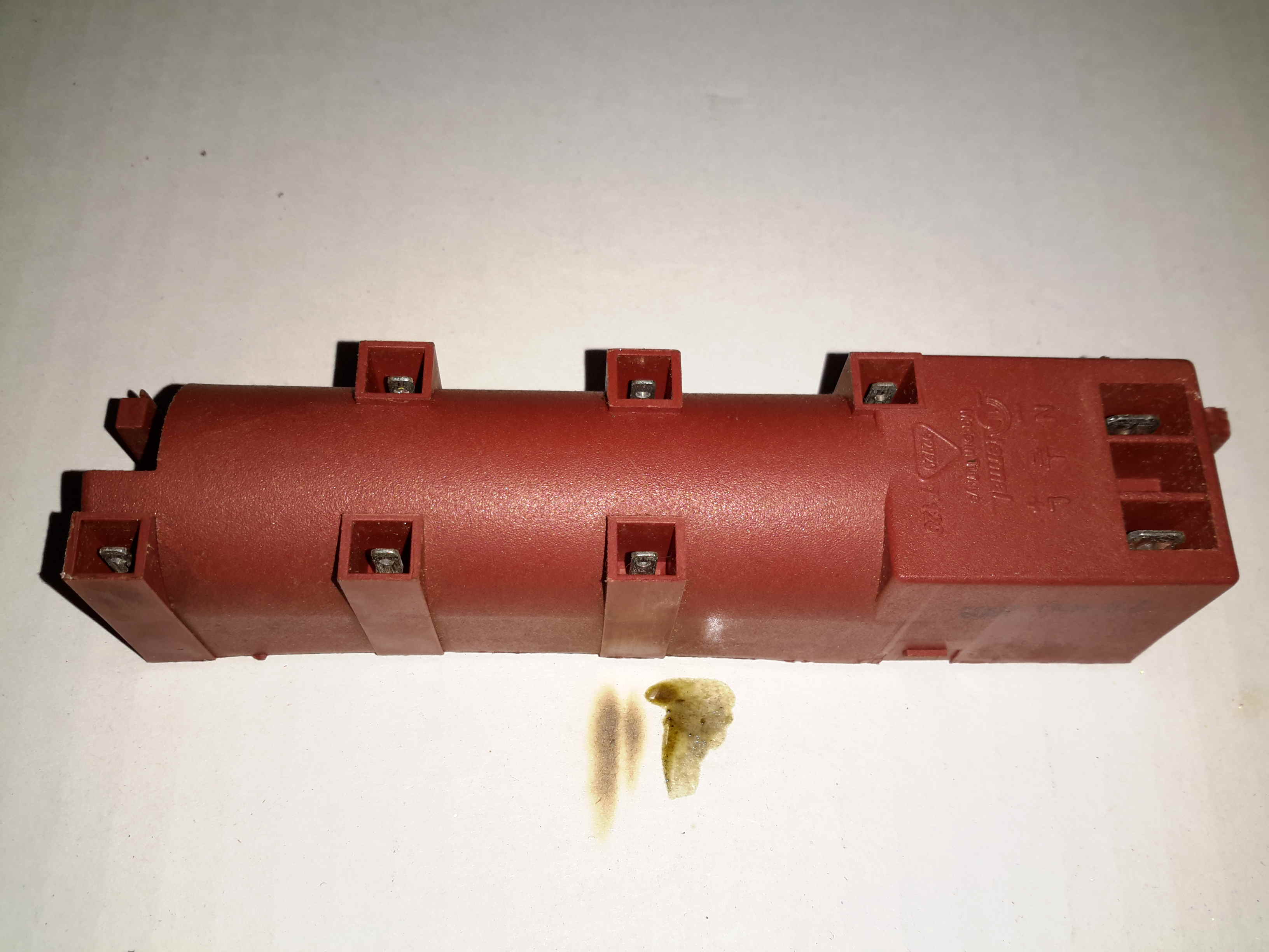
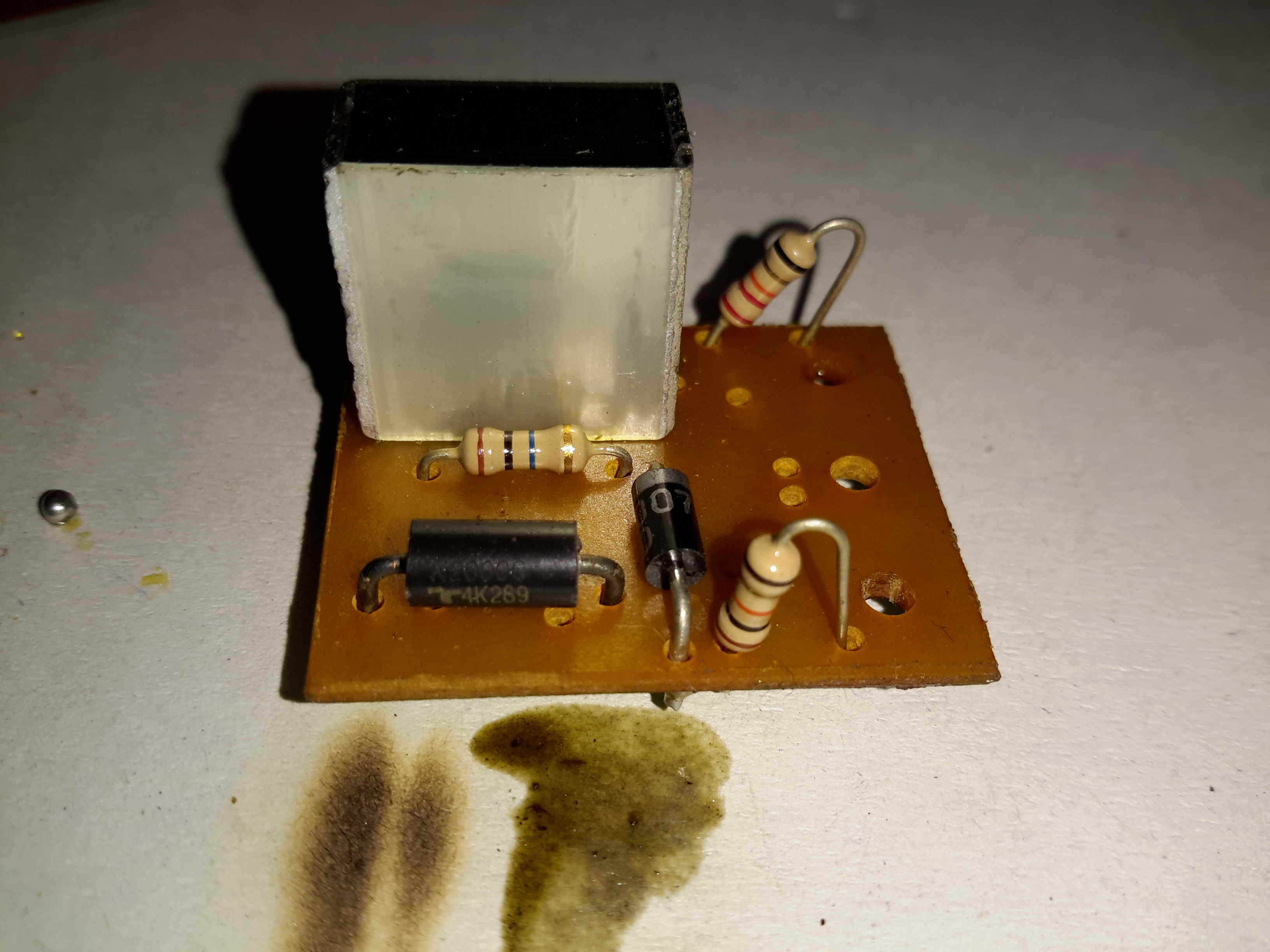
Here’s a quick teardown of an ignition transformer, used on gas fired ovens & hobs. This unit takes mains 240v AC & uses a transformer to step the voltage to several kV, at a low current to ignite the burners.
Bottom
The transformer section is completely potted in Epoxy resin for insulation, but the driver circuitry is exposed, with a pair of leads from the primary winding exposed
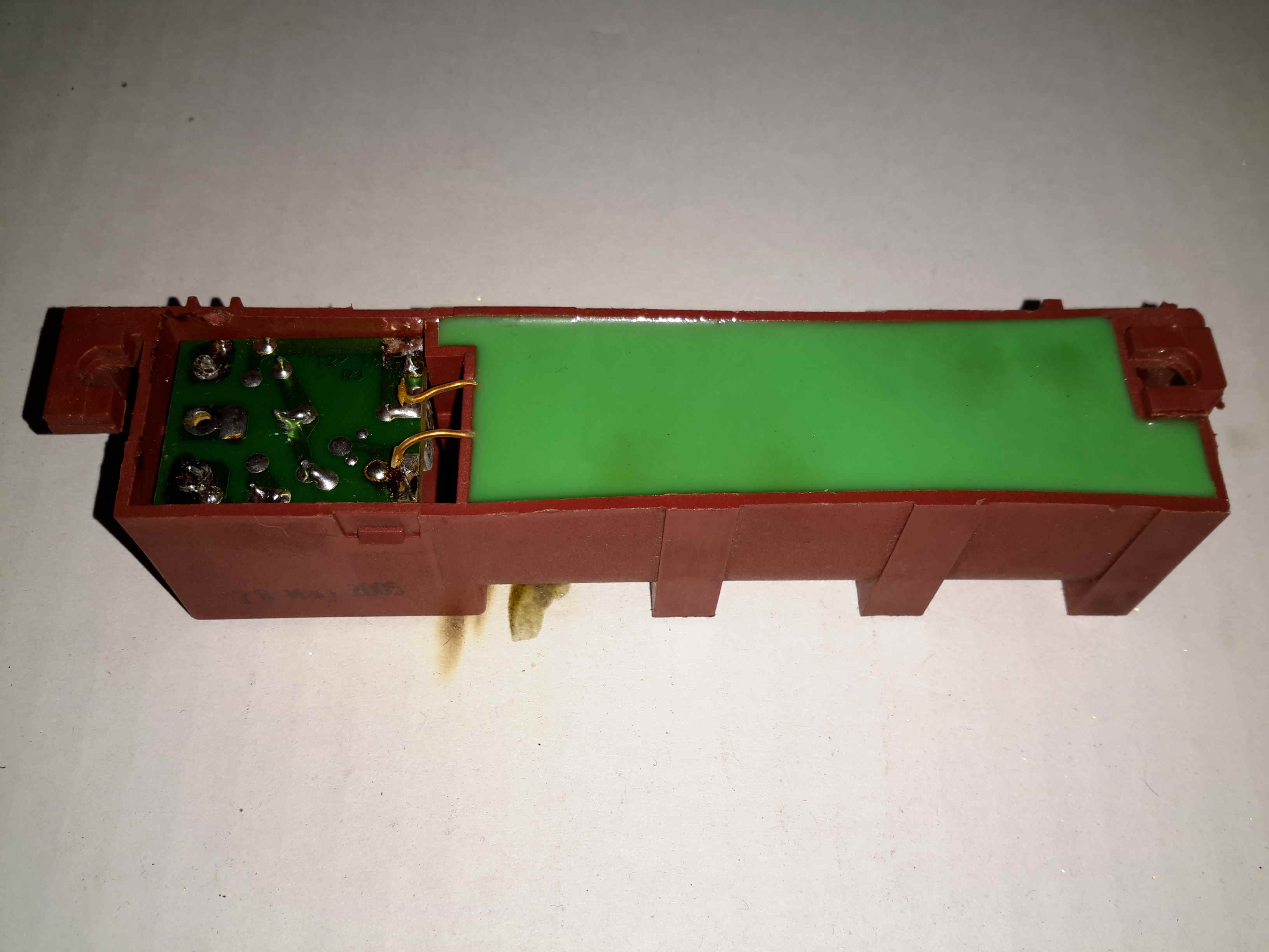
Driver PCB
The drive is very simple. The incoming AC flows through a series resistor through a half-wave rectifier to charge up a 2.2µF film capacitor. Once the voltage on the capacitor reaches a certain level, a DIAC in series with the transformer primary fires, discharging the capacitor through the primary.
The current spike induces a very high voltage on the secondary winding, this then arcs across a gap in the gas flow to start ignition.
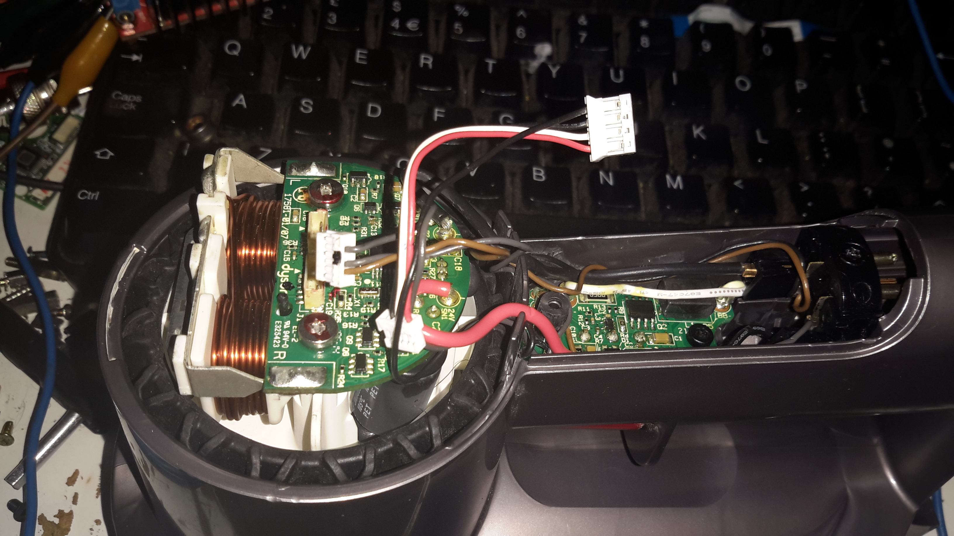
Here’s another Dyson teardown, in my efforts to understand how marketing have got hold of relatively simple technology & managed to charge extortionate amounts of money for it.
This is the DC35, the model after the introduction of the brushless digital motor.
Back Cap Removed
On this version the mouldings have been changed, and the back cover comes off, after removing the battery retaining screw. It’s attached with some fairly vicious clips, so some force is required. Once the cap is removed, all the electronics are visible. On the left is the motor itself, with it’s control & drive PCB. There’s another PCB on the trigger, with even more electronics. The battery connector is on the right.
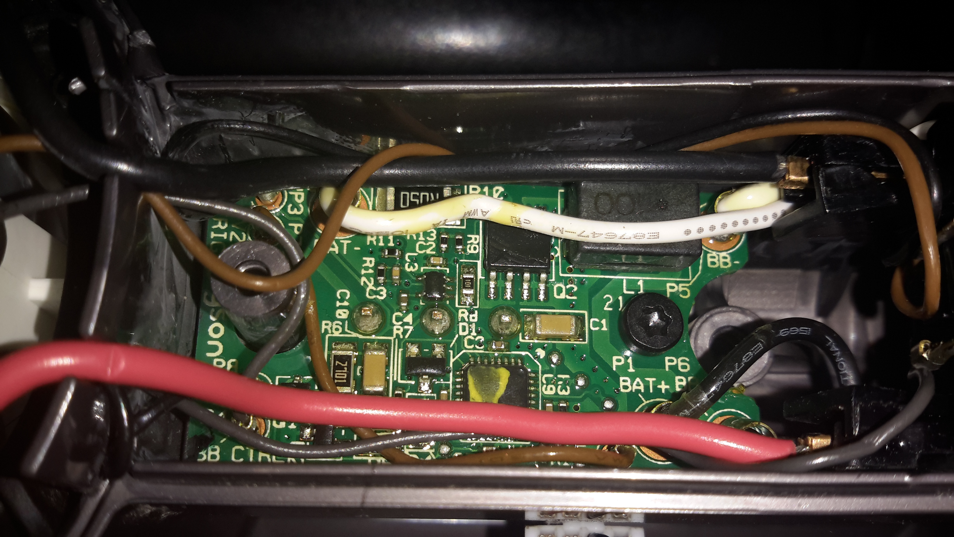
Trigger PCB
Here’s the trigger PCB, which appears to deal with DC-DC conversion for powering the brush attachments. The QFN IC with yellow paint on it is an Atmel ATTiny461 8-bit microcontroller. This is probably controlling the DC-DC & might also be doing some battery authentication.
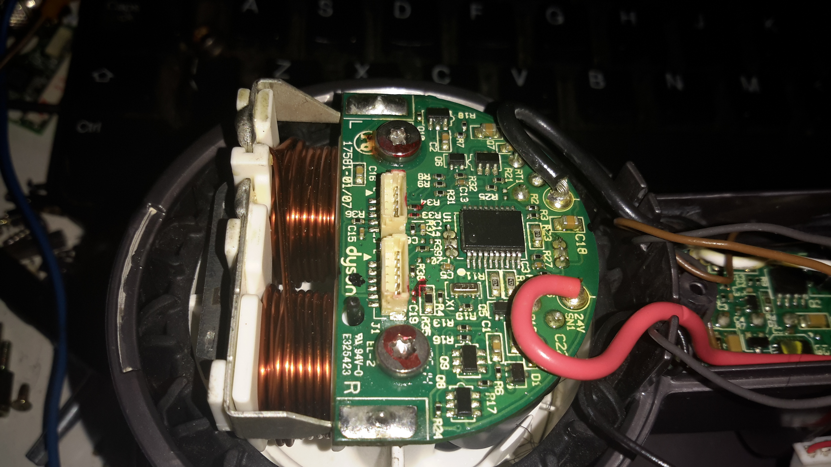
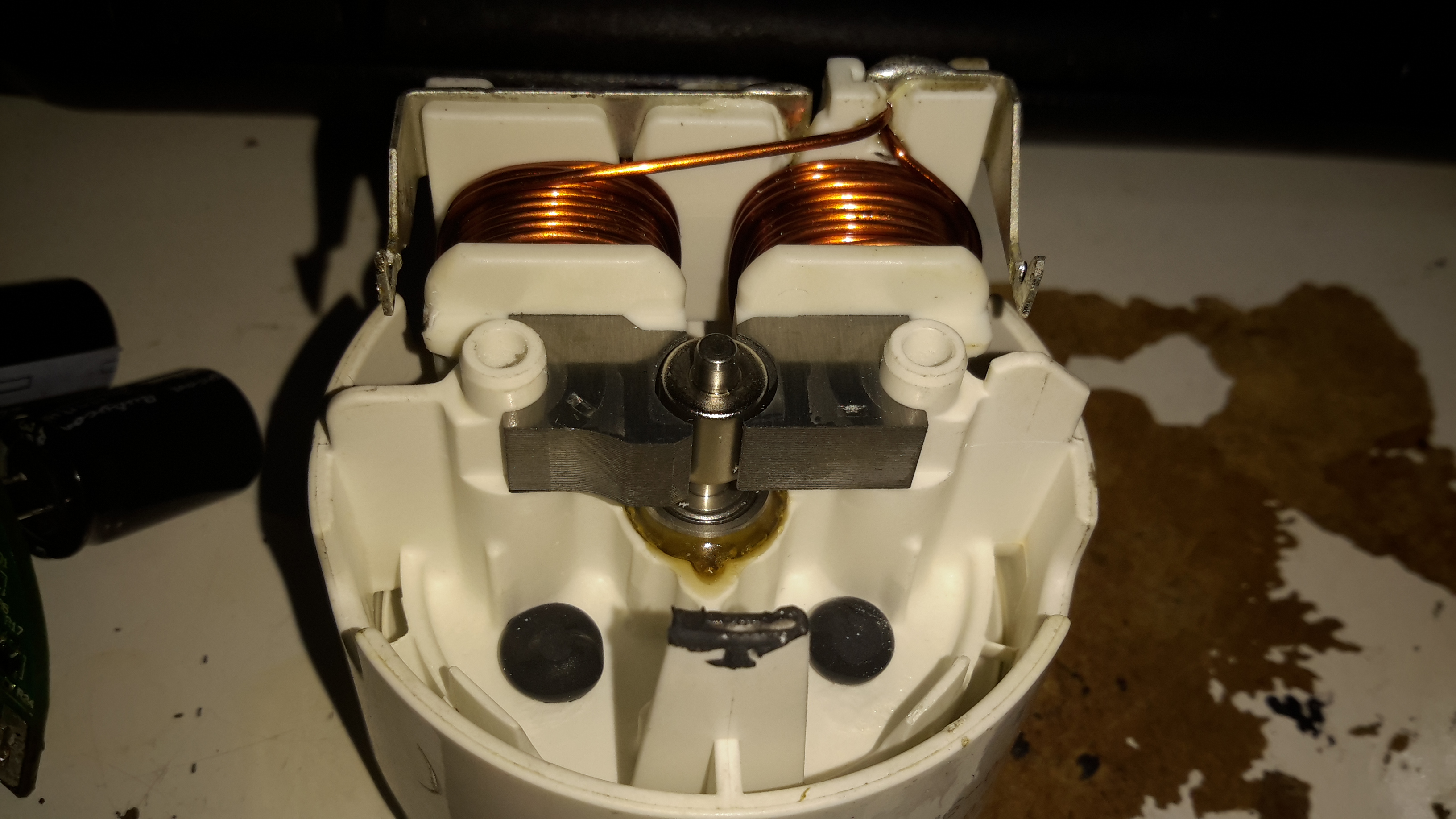
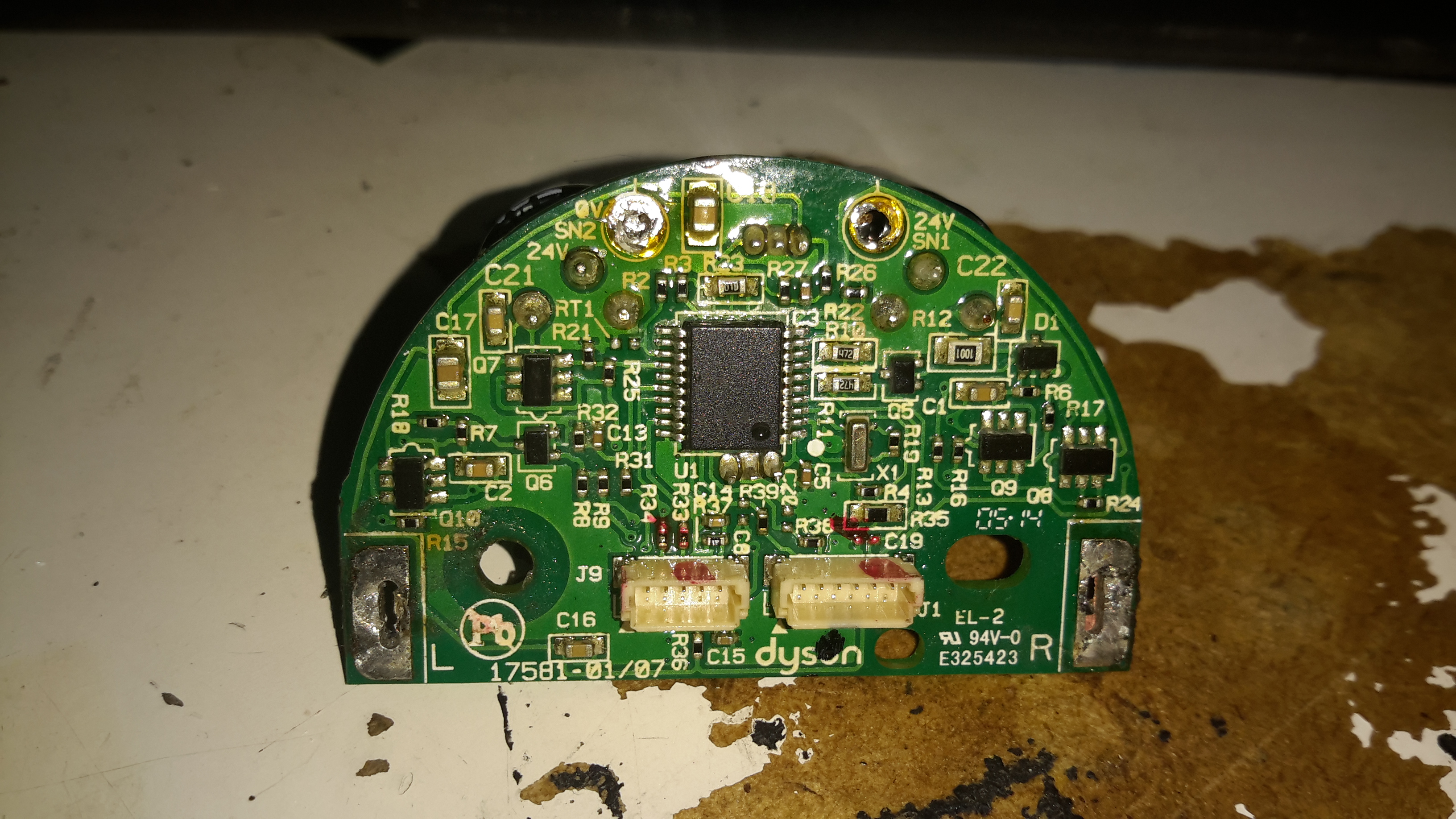
“Digital Motor”
Here’s the motor & it’s board. The windings on the stator are extremely heavy, which makes sense considering it’s rated at 200W. The main control IC is a PIC16F690 from Microchip. Instead of using an off the shelf controller, this no doubt contains software for generating the waveforms that drive the brushless motor. It also appears to communicate with the other PCBs for battery authentication.
Stator
Desoldering the board allows it to be removed from the motor itself. The pair of windings are connected in anti-phase, to create alternating North-South poles depending on polarity. Since the existing controller is unusable due to software authentication with the other parts, I might have a go at building my own driver circuit for this with an Arduino or similar.
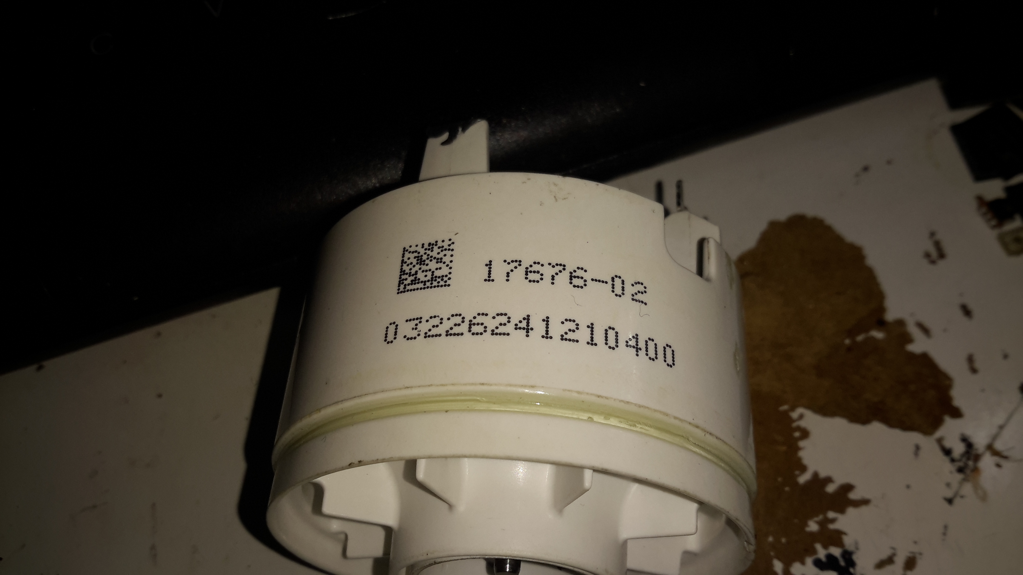
Blower Assembly
The blower assembly is simple plastic mouldings, pressed together then solvent welded at the seam.
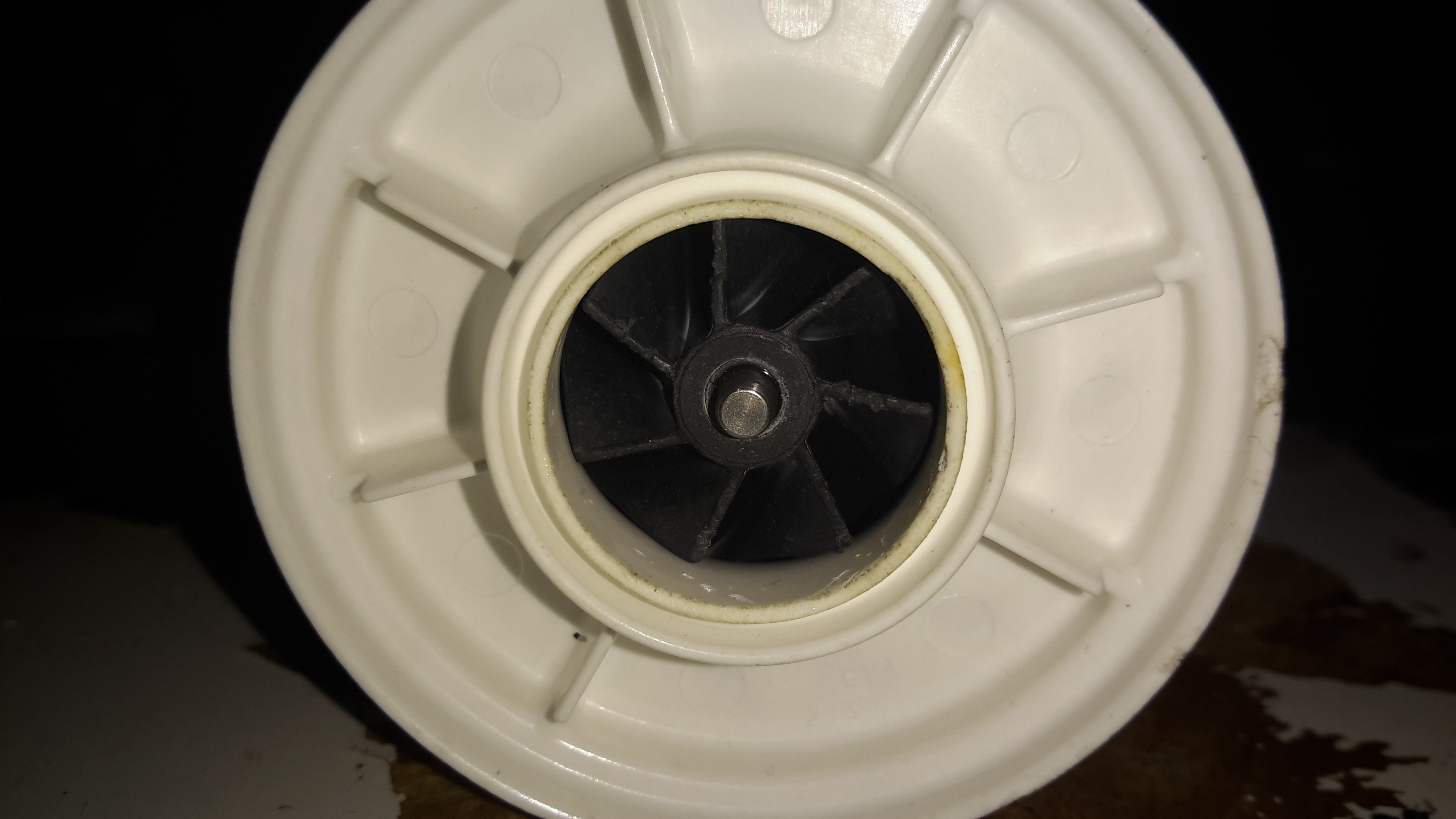
Impeller
The impeller is just a centrifugal compressor wheel, identical to what’s used in engine turbochargers.
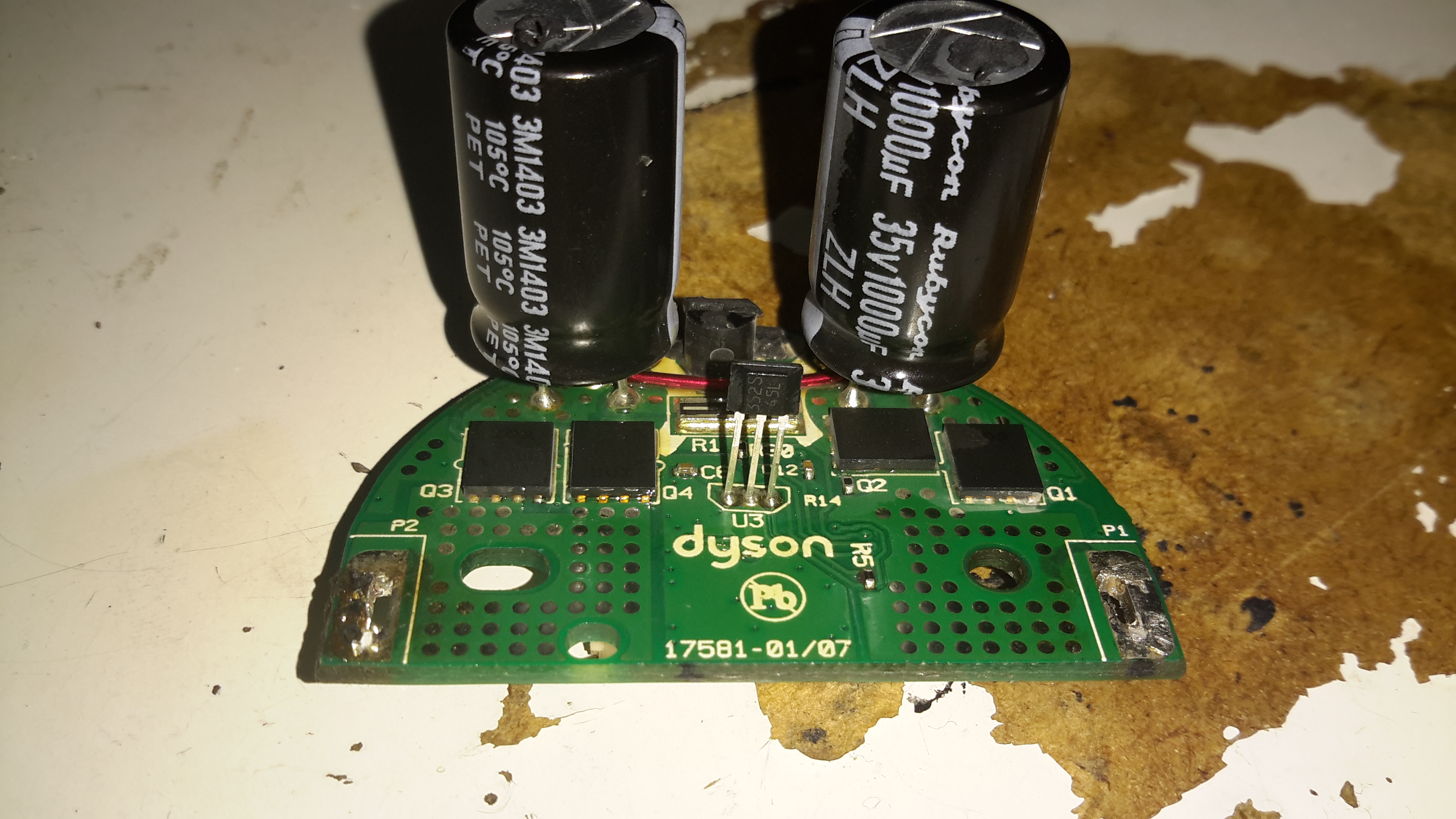
Motor Control Board
The inside face of the control PCB holds the 4 very large MOSFETs, IRFH7932PbF from International Rectifier. These are rated at 30v 20A a piece, and are probably wired in a H-Bridge. There’s a bipolar Hall switch to sense rotor position & rotation speed, and an enormous pair of capacitors on the main power bus.
Motor Control Board Reverse
Not much on the other side of the PCB other than the microcontroller and associated gate drive stuff for the FETs.
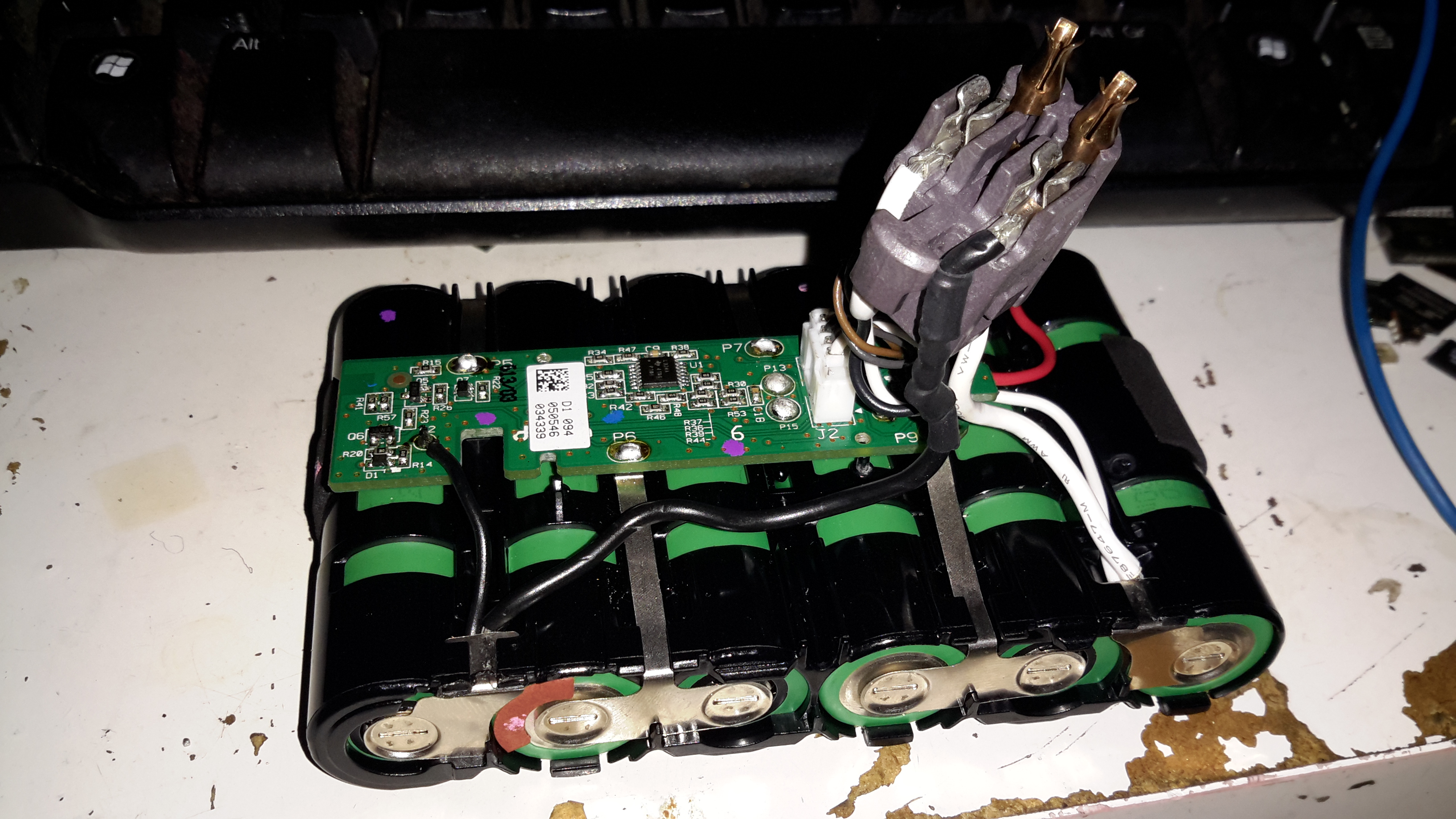
Battery Pack Opened
The battery pack is similar to the DC16 in it’s construction, a heavily clipped together plastic casing holding 6 lithium cells. In this one though there’s a full battery management system. The IC on the top of the board above is a quad Op-Amp, probably for measuring cell voltages.
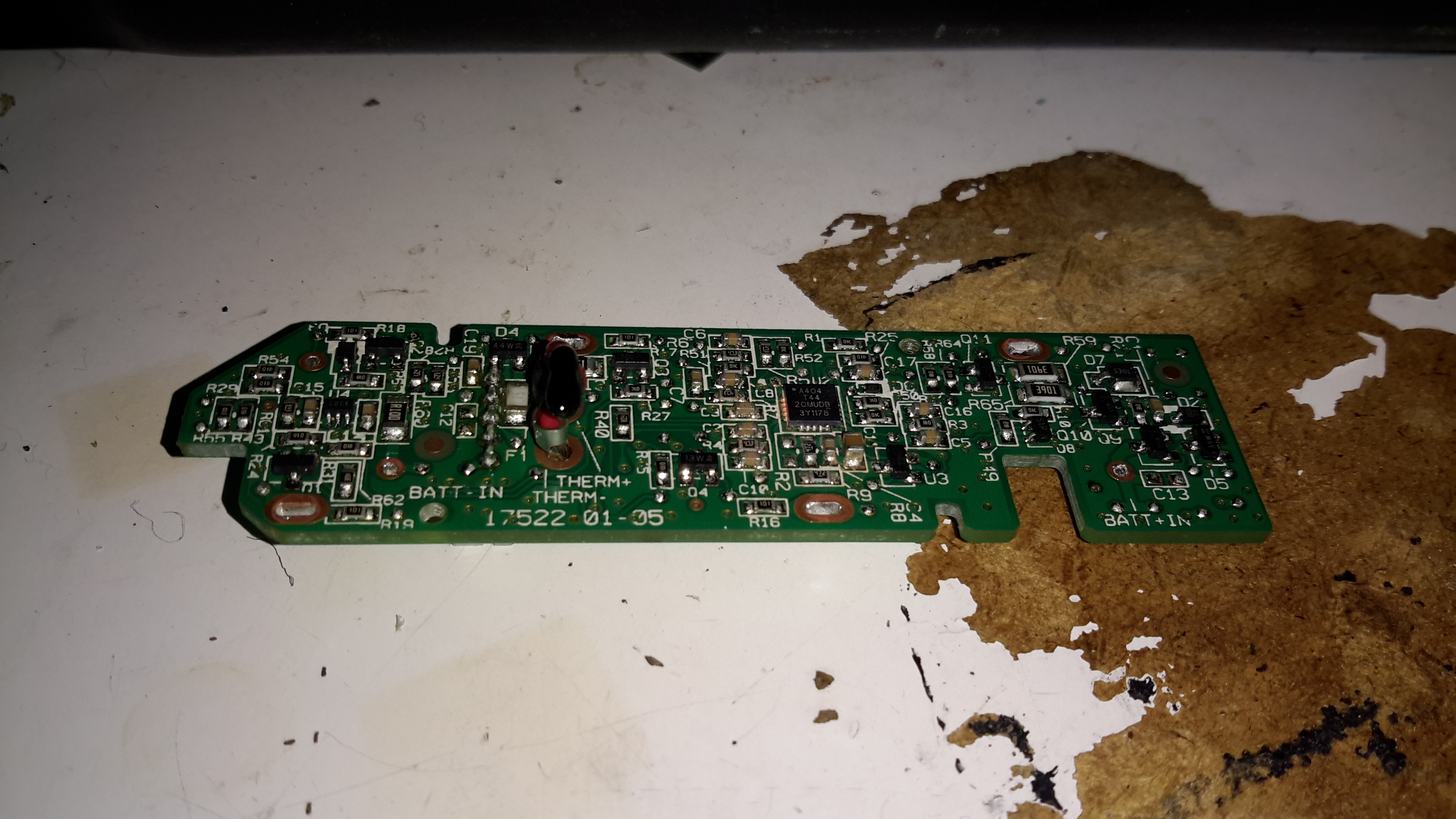
Battery BMS Bottom
The other side of the BMS board is packed with components. I wasn’t able to identify the QFN IC here, as it’s got a custom part number, but it’s most definitely communicating with the main motor MCU via I²C over the two small terminals on the battery connector.
The multimode dimming/flashing modes on Chinese torches have irritated me for a while. If I buy a torch, it’s to illuminate something I’m doing, not to test if people around me have photosensitive epilepsy.
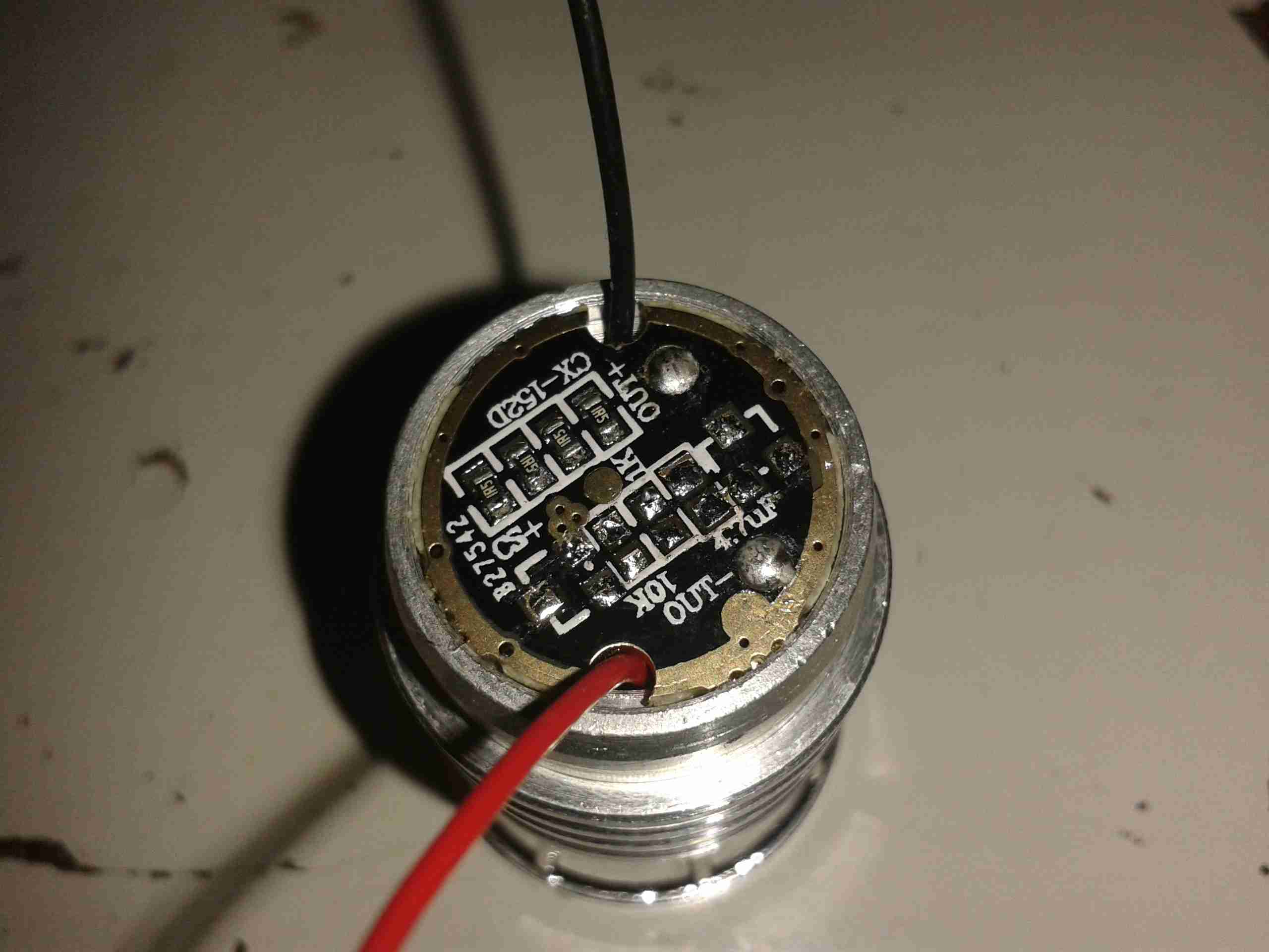
Looking at the PCB in the LED module of the torch, a couple of components are evident:
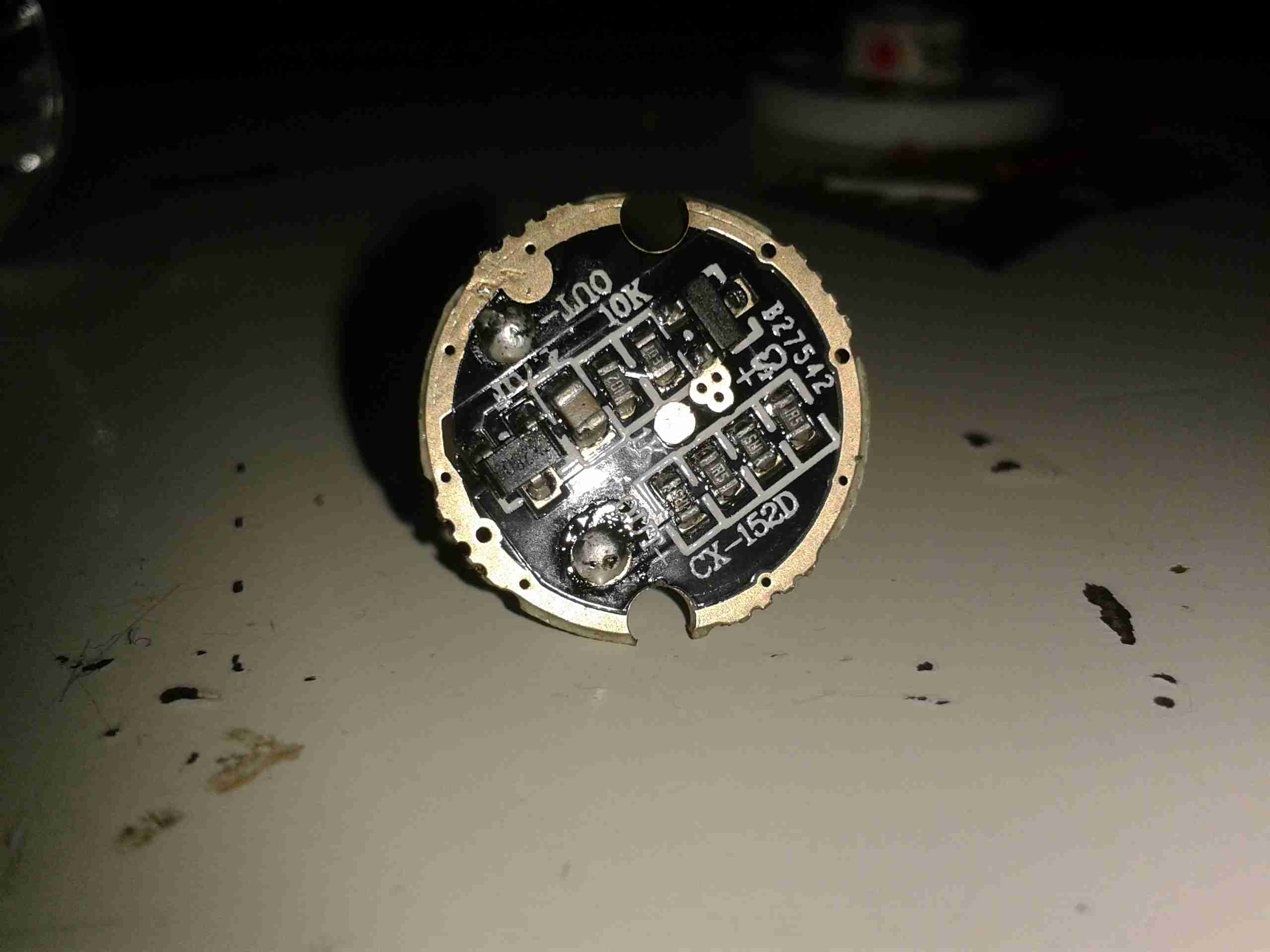
LED Driver PCB
There’s not much to this driver, it’s simply resistive for LED protection (the 4 resistors in a row at the bottom of the board).
The components at the top are the multimode circuitry. The SOT-23 IC on the left is a CX2809 LED Driver, with several modes. The SOT-23 on the right is a MOSFET, for switching the actual LED itself. I couldn’t find a datasheet for the IC itself, but I did find a schematic that seems to match up with what’s on the board.
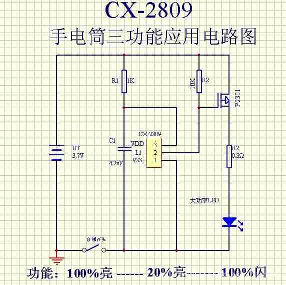
Schematic
Here’s that schematic, the only thing that needs to be done to convert the torch to single mode ON/OFF at full brightness, is to bridge out that FET.
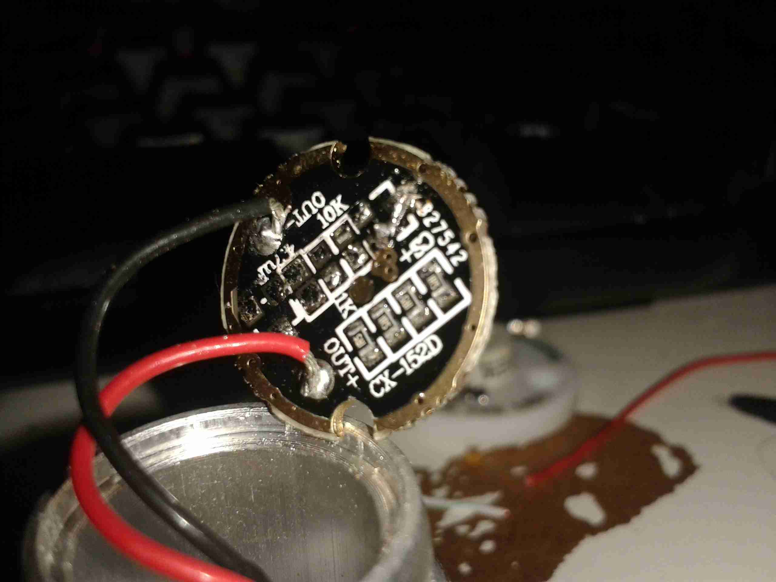
Components Desoldered
To help save the extra few mA the IC & associated circuitry will draw from the battery, I have removed all of the components involved in the multimode control. This leaves just the current limiting resistors for the LED itself.
Jumper Link
The final part above, is to install a small link across the Drain & Source pads of the FET. Now the switch controls the LED directly with no silly electronics in between. A proper torch at last.
I recently dug out my other card printer to fit it with a 12v regulator, (it’s 24v at the moment), and figured I’d do a teardown post while I had the thing in bits.
This is a less industrial unit than my Zebra P330i, but unlike the Zebra, it has automatic duplexing, it doesn’t have Ethernet connectivity though.
Unlike domestic printers, which are built down to a price, these machines are very much built up to a spec, and feature some very high quality components.
Naked Printer
Here’s the mechanism with the cowling removed. This is the main drive side of the printer, with the main drive stepper at left, ribbon take-up spool motor lower right, and the duplex module stepper motors at far right.
Main Motor Drive
The main drive motor runs the various rollers in the card path through a pair of synchronous belts, shown here.
Main Stepper
The stepper itself is a quality ball-bearing Sanyo Denki bipolar motor.
Main Stepper Driver
Electrical drive is provided to the stepper with a L6258EX DMOS universal motor driver. This chip can also drive DC motors as well as steppers.
Ribbon Supply Spool
Here is the encoder geared onto the ribbon supply spool. This is used to monitor the speed the ribbon is moving relative to the card.
Printer Top
Here’s a top view through the printer, the blue roller on the left cleans the card as it’s pulled from the feeder, the gold coloured spool to it’s right is the ribbon supply reel. The cooling fan on the right serves to stop the print head overheating during heavy use.
Spool Take Up Motor
The spool take-up reel is powered by another very high quality motor, a Buhler DC gearmotor. These printers are very heavily over engineered!
This motor drives the spool through an O-Ring belt, before the gear above. This allows the drive to slip in the event the ribbon jams, preventing it from breaking.
Duplex Unit Stepper Drivers
The pair of steppers that operate the duplexing unit are driven by a separate board, with a pair of L6219DS bipolar stepper driver ICs. There are also a couple of opto-sensors on this board for the output hopper.
Main Control PCB
All the mechanisms of the printer are controlled from this main PCB, which handles all logic & power supply functions. Sections on the board are unpopulated, these would be for the Ethernet interface, smart card programming & magstripe programming.
Main CPU
The brains of the operation is this ColdFire MCF5208CVM166 32-bit microprocessor. It features 16KB of RAM, 8KB of cache, DMA controller, 3 UARTs, SPI, 10/100M Ethernet and low power management. This is a fairly powerful processor, running at 166MHz.
It’s paired with an external 128Mbit SDRAM from Samsung, and a Spansion 8Mbit boot sector flash, for firmware storage.
USB Interface & Power Input
Here the USB interface IC is located. It’s a USBN9604 from Texas Instruments, this interfaces with the main CPU via serial.
As there was no other online example of someone converting a glow/nitro car engine onto CDI ignition, I thought I would document the highlights here.
The engine is currently still running on glow fuel, but when the required fuel lines arrive I will be attempting the switch over to 2-Stroke petrol mix. This should definitely save on fuel costs.
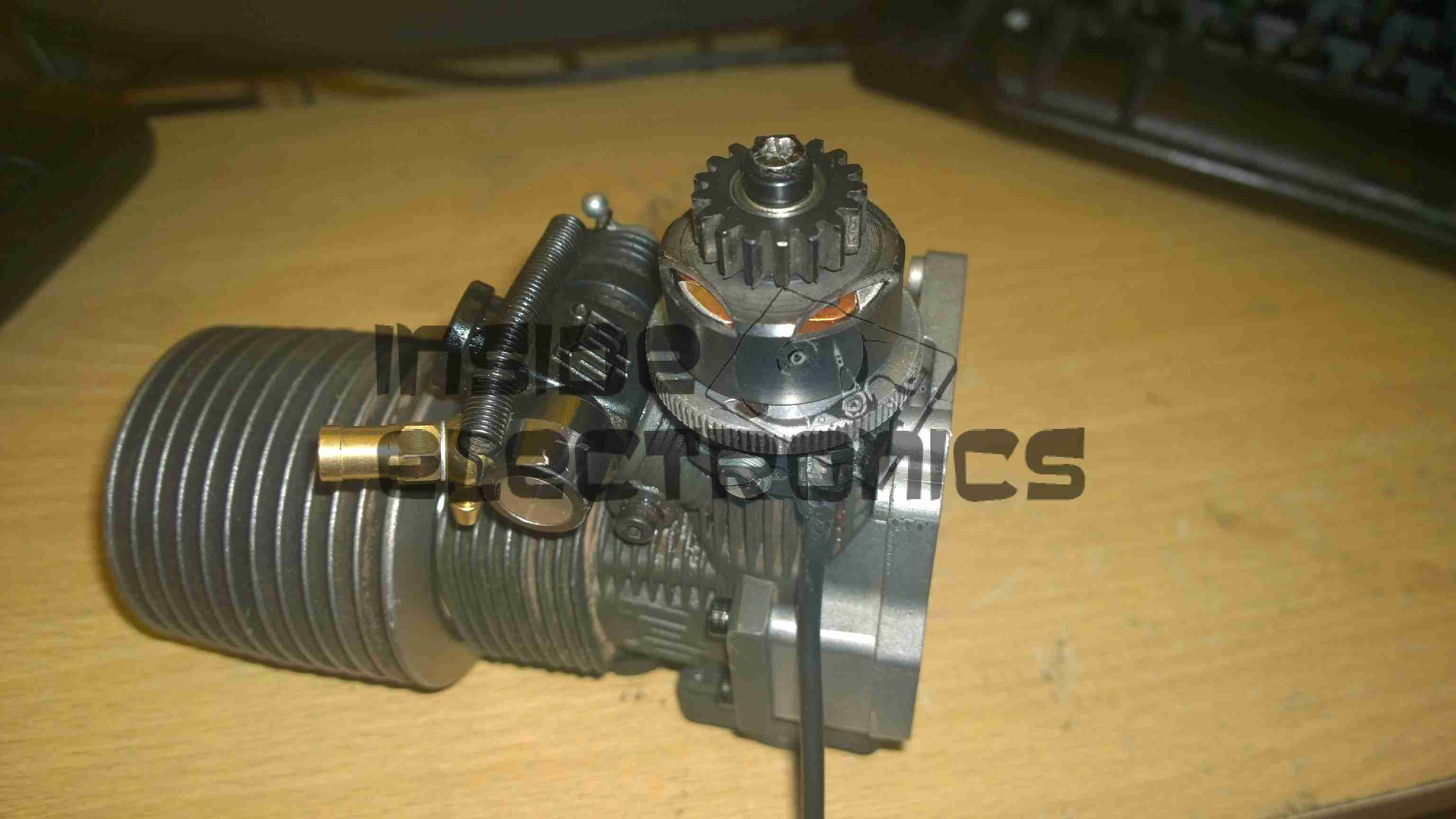
The engine in this case is a HPI NitroStar F4.6 nitro engine, from a HPI Savage X monster truck.
F4.6 Engine
Above is the converted engine with it’s timing sensor. As The installation of this was pretty much standard, a complete strip down of the engine was required to allow the drilling & tapping of the two M3x0.5 holes to mount the sensor bracket to. The front crankshaft bearing has to be drifted out of the crankcase for this to be possible.
Ignition Hall Sensor
Detail of the ignition hall sensor. The bracket has to be modified to allow the sensor to face the magnet in the flywheel. Unlike on an Aero engine, where the magnet would be on the outside edge of the prop driver hub, in this case the hole was drilled in the face of the flywheel near the edge & the magnet pressed in. The Hall sensor is glued to the modified bracket with the leads bent to position the smaller face towards the back of the flywheel.
The clearance from the magnet to sensor is approx. 4mm.
Flywheel Magnet
Detail of the magnet pressed into the flywheel. A 3.9mm hole was drilled from the back face, approx 2mm from the edge, & the magnet pressed into place with gentle taps from a mallet & drift, as I had no vice to hand.
Initial timing was a little fiddly due to the flywheel only being held on with a nut & tapered sleeve, so a timing mark can be made inside the rear of the crankcase, across the crank throw & case to mark the 28 degree BTDC point, the flywheel is then adjusted to make the ignition fire at this point, before carefully tightening the flywheel retaining nut to ensure no relative movement occurs.
The slots in the sensor bracket allow several degrees of movement to fine adjust the timing point once this rough location has been achieved.
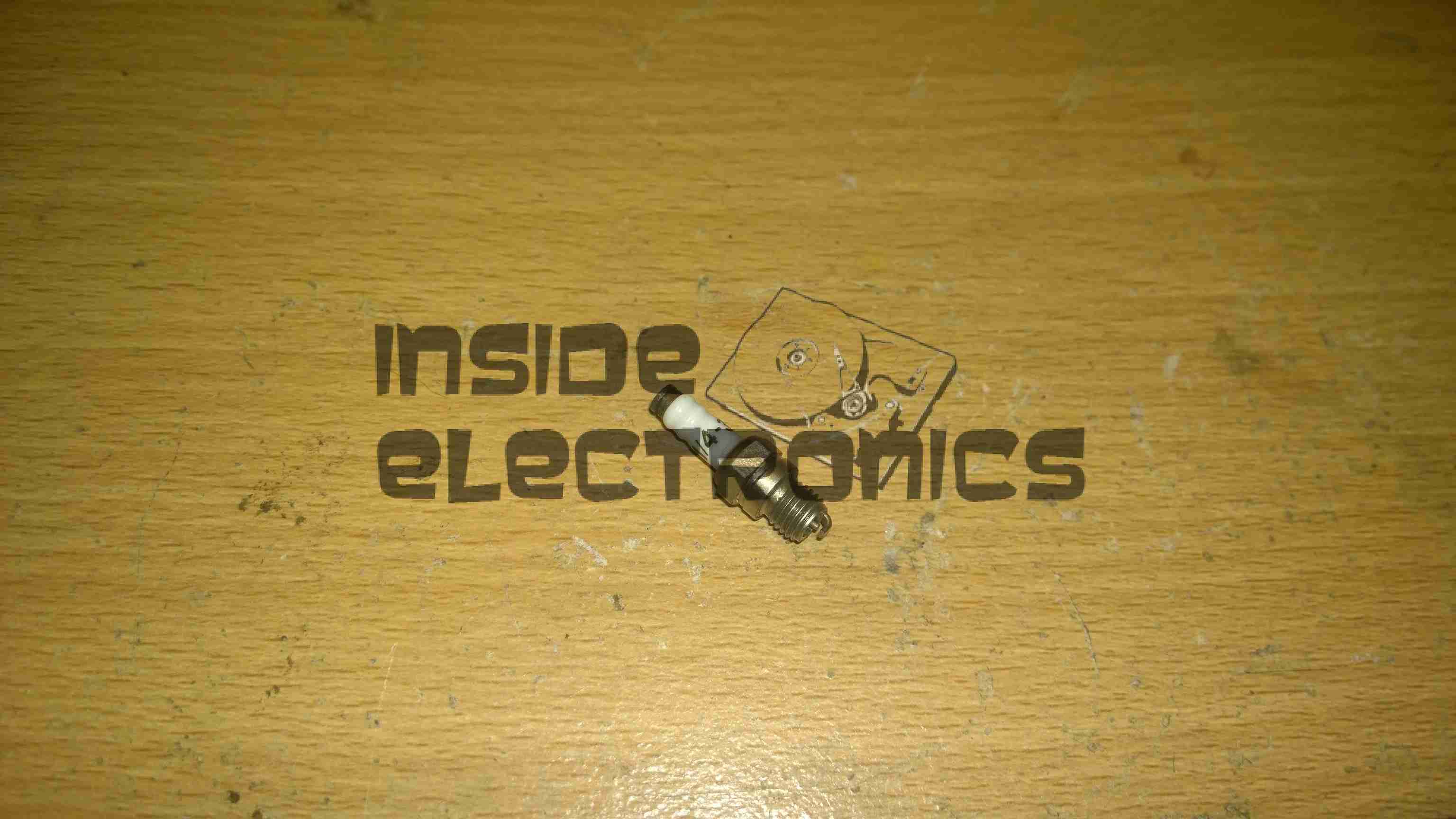
1/4″-32 Spark Plug
Definitely the tiniest spark plug I’ve ever seen, about an inch long. Some trouble may be encountered with this on some engines – the electrodes stick out about 2mm further into the combustion chamber than a standard glow plug does. This causes the ground electrode to hit the top of the piston crown. (This happens on the HPI NitroStar 3.5 engine). The addition of another copper washer under the plug before tightening should cure this problem.
RcExl CDI Ignition Module
Ignition module. Due to the depth of the plug in the heatsink head on these engines, I will have to modify the plug cap to straighten it out, as it will not fit in this configuration.
However, ignition modules are available from HobbyKing with straight plug caps, this makes modification unnecessary
The ignition & components used on this system were obtained from JustEngines.
Just a short script to directly print files to the NCR 7197 Series printers under Linux as there is no direct driver. Certainly not finished or pretty, but functional.
#/bin/sh
###Depends on fmt & iconv for file formatting for printer to operate correctly. Also expects UTF-8 encoded text files.

if [ "$1" == "--help" ];
    then
		echo "NCR 7197 file printing Script"
		echo "Usage:"
		echo "./ReceiptPrinter.sh <FILE> <SERIAL PORT NUMBER>"
		echo "To trim paper off, pass --cut parameter with port number instead of file name."
		echo "This script is currently set up for USB Connection of the printer"
		echo "Make sure your user has access to the serial port you intend to use,"
		echo "otherwise an error will occur"
		echo "This script uses fmt & iconv to format the provided text file for the printer."
		echo "This is 44 characters wide, word wrap enabled & format conversion to US English"

	else
		if [ "$1" == "--cut" ];
			then
				echo -e "\x1B\x07\x1D\x56\x41\x06" > /dev/ttyUSB$2
				echo "Scissor Operated"
				exit 0
	else
		if [ ! -z "$1" ];
			then
				cat $1 | fmt -w 44 | iconv -f UTF-8 -t ISO-8859-1//TRANSLIT > /dev/ttyUSB$2
				echo -e "\x1D\x56\x41\x06" > /dev/ttyUSB$2
				echo "Print Complete"
				exit 0
			else
			echo "No File provided!!! Returning to shell!"
			fi
		fi
	fi
exit 0
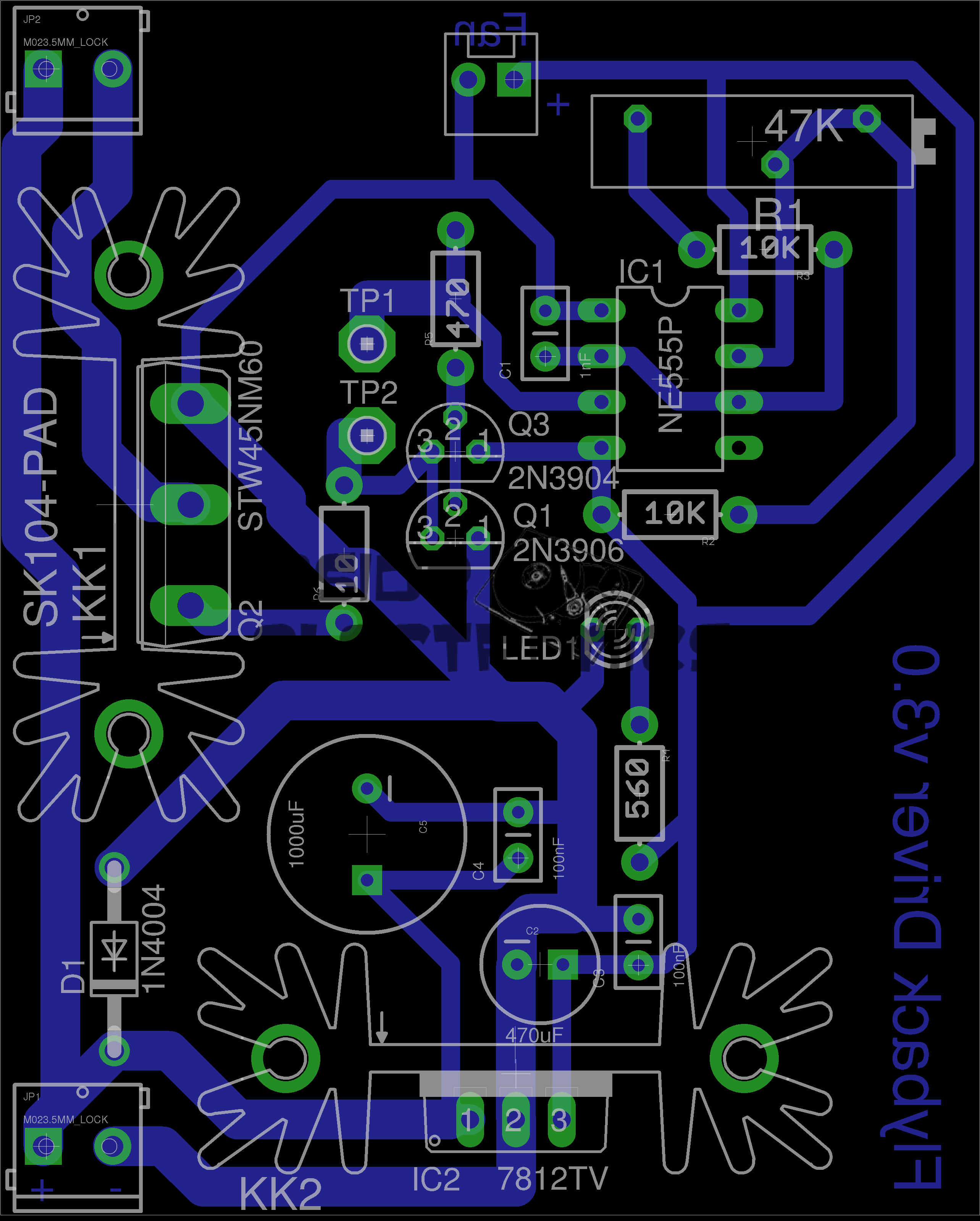
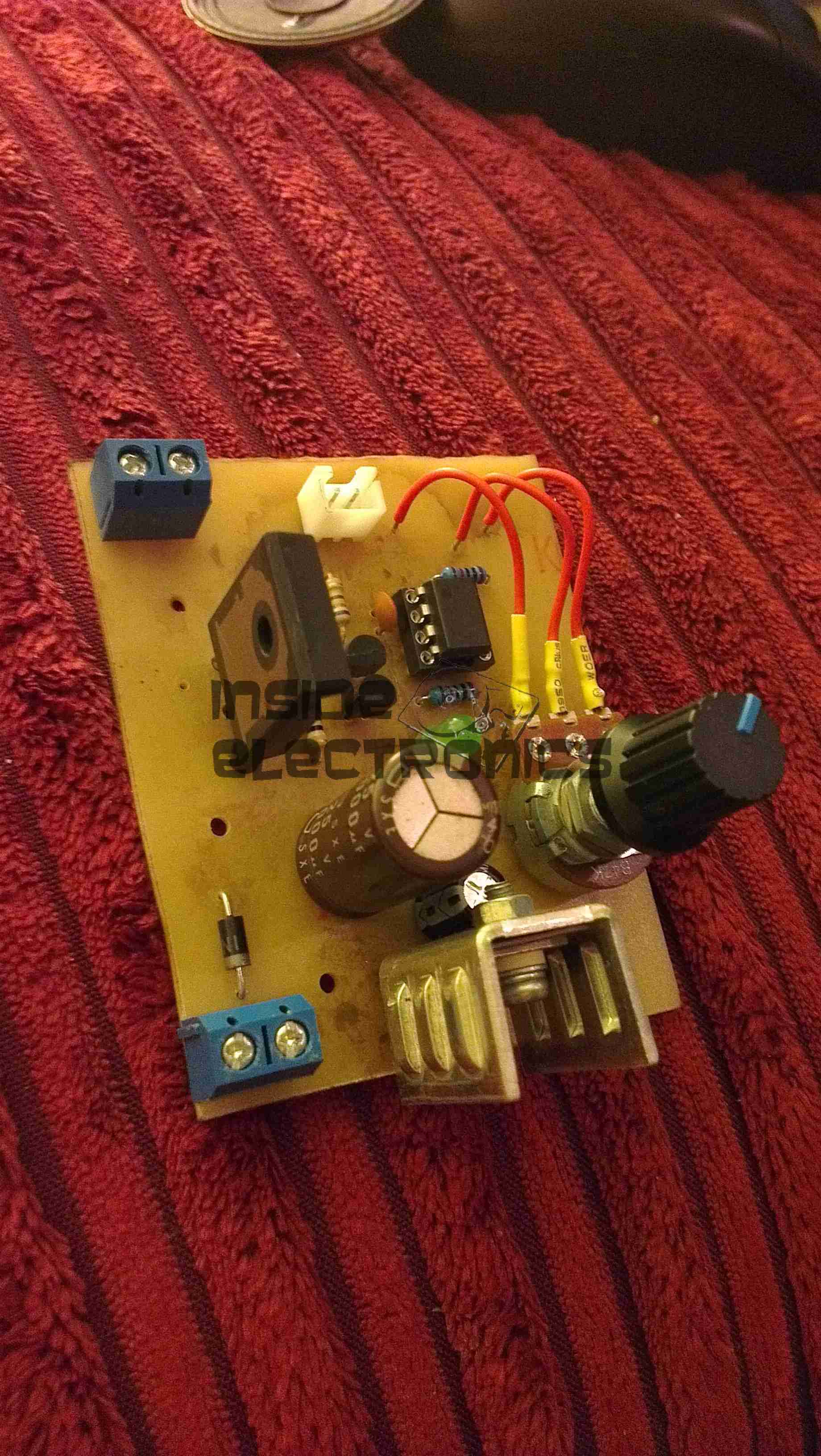
Here is a simple 555 timer based flyback transformer driver, with the PCB designed by myself for some HV experiments. Above is the Eagle CAD board layout.
The 555 timer is in astable mode, generating a frequency from about 22kHz to 55kHz, depending on the position of the potentiometer. The variable frequency is to allow the circuit to be tuned to the resonant frequency of the flyback transformer in use.
This is switched through a pair of buffer transistors into a large STW45NM60 MOSFET, rated at 650v 45A.
Input power is 15-30v DC, as the oscillator circuit is fed from an independent LM7812 linear supply.
Provision is also made on the PCB for attaching a 12v fan to cool the MOSFET & linear regulator.
Initial Board
Board initially built, with the heatsink on the linear regulator fitted. I used a panel mount potentiometer in this case as I had no multiturn 47K pots in stock.
PCB Traces
Bottom of the PCB. The main current carrying traces have been bulked up with copper wire to help carry the potentially high currents on the MOSFET while driving a large transformer.
This board was etched using the no-peel toner transfer method, using parchement paper as the transfer medium.
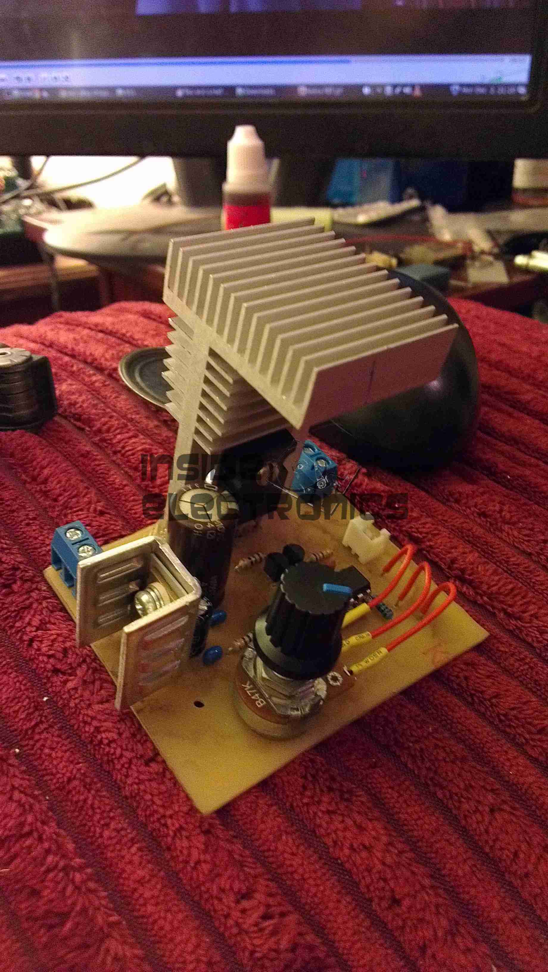
MOSFET Heatsinked
Main MOSFET now fitted with a surplus heatsink from an old switchmode power supply. A Fan could be fitted to the top of this sink to cope with higher power levels.
Gate Drive Waveform
This is the gate drive waveform while a transformer is connected, the primary is causing some ringing on the oscillator. The waveform without an attached load is a much cleaner square wave.
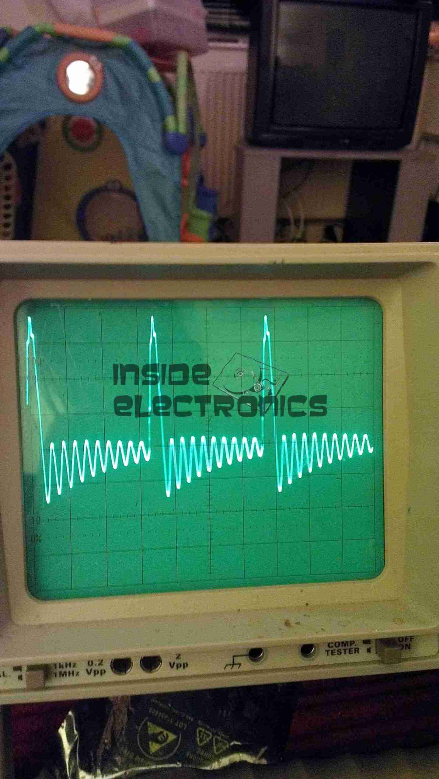
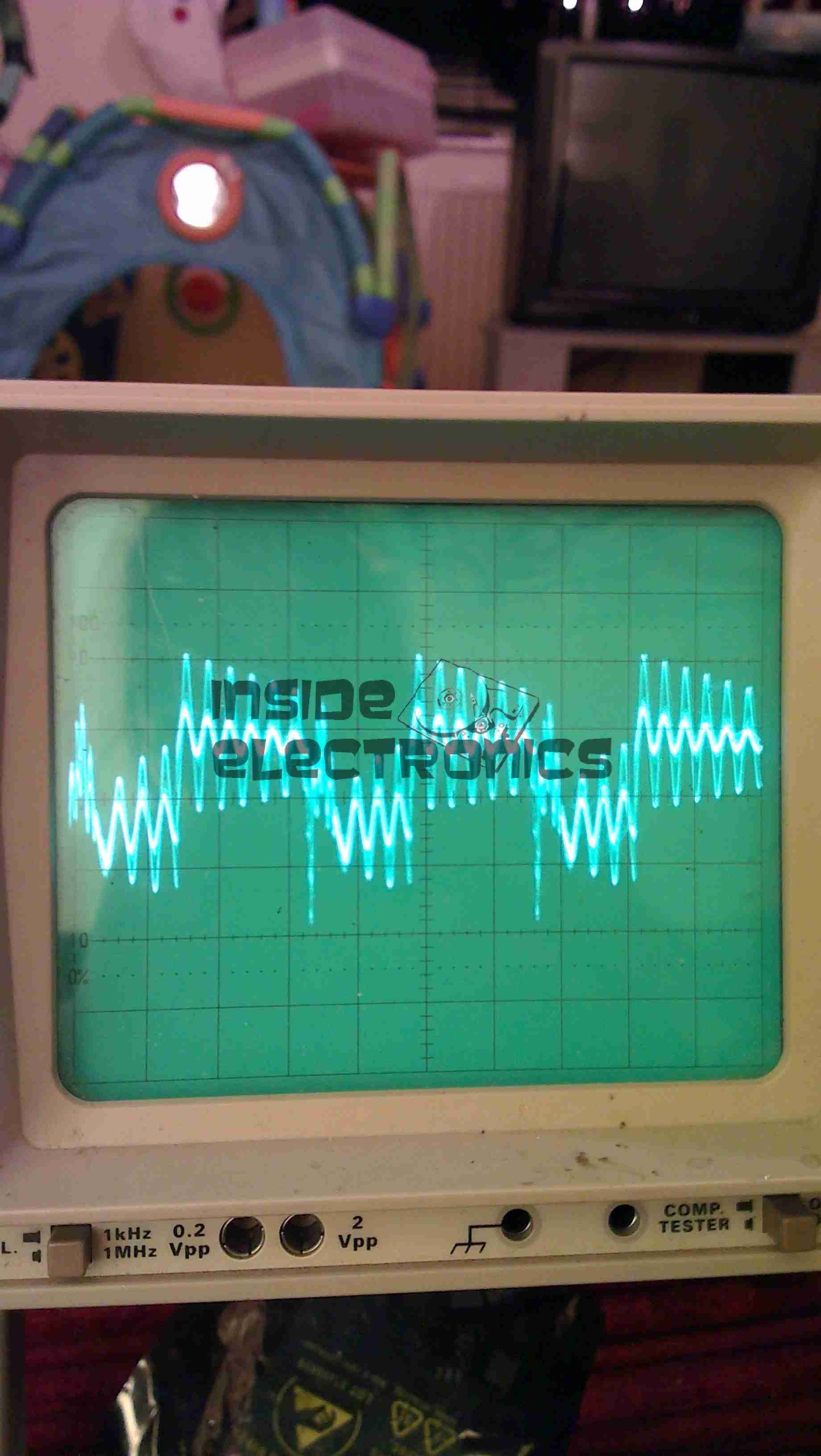
Flyback Secondary Waveform
I obtained a waveform of the flyback secondary output by capacitively coupling the oscilloscope probe through the insulation of the HT wire. The pulses of HV can be seen with the decaying ringing of the transformer between cycles.
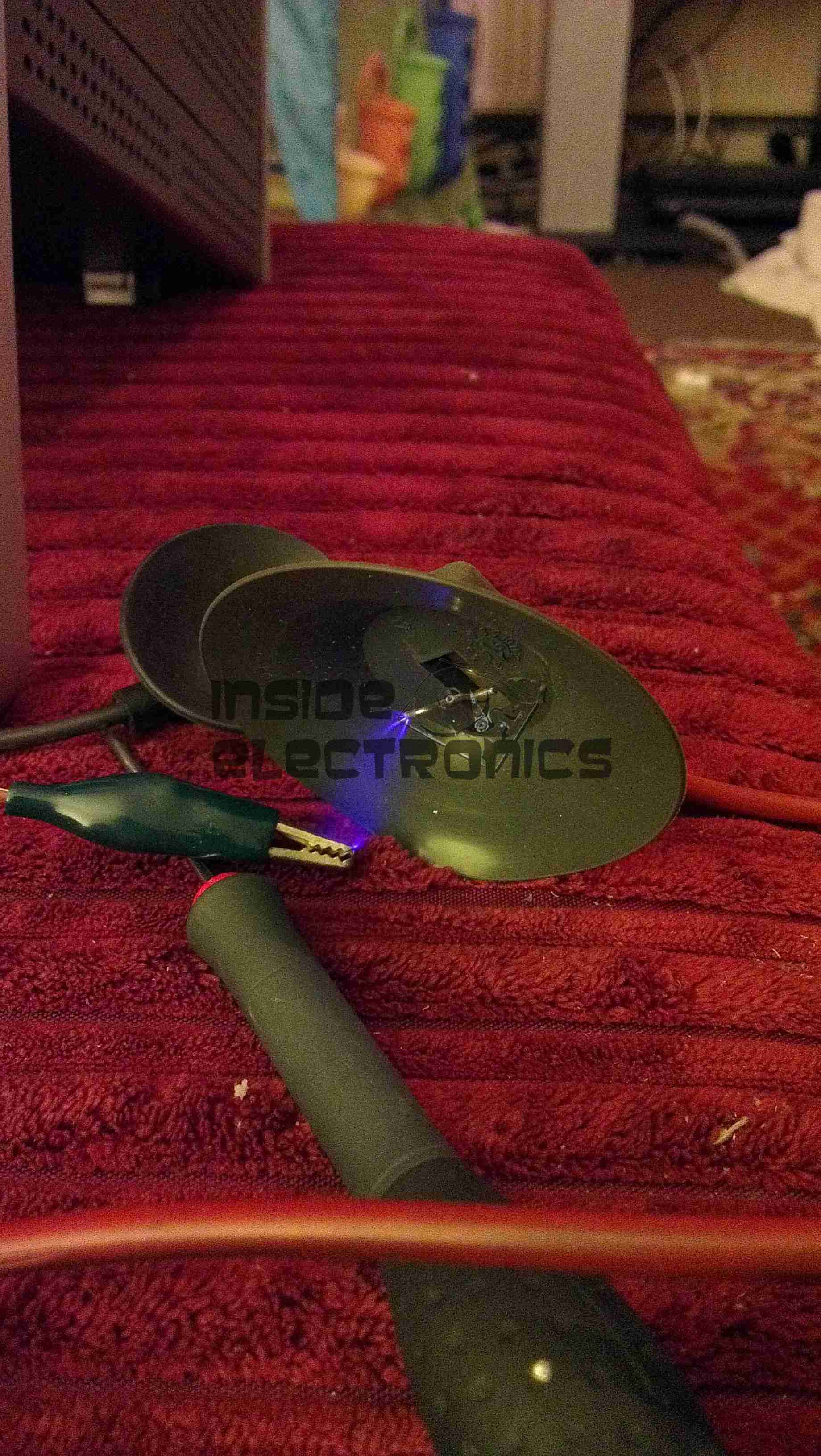
Corona DischargeArc Discharge
Corona & arc discharges at 12v input voltage.
Download the Eagle schematic files here: [download id=”5561″]
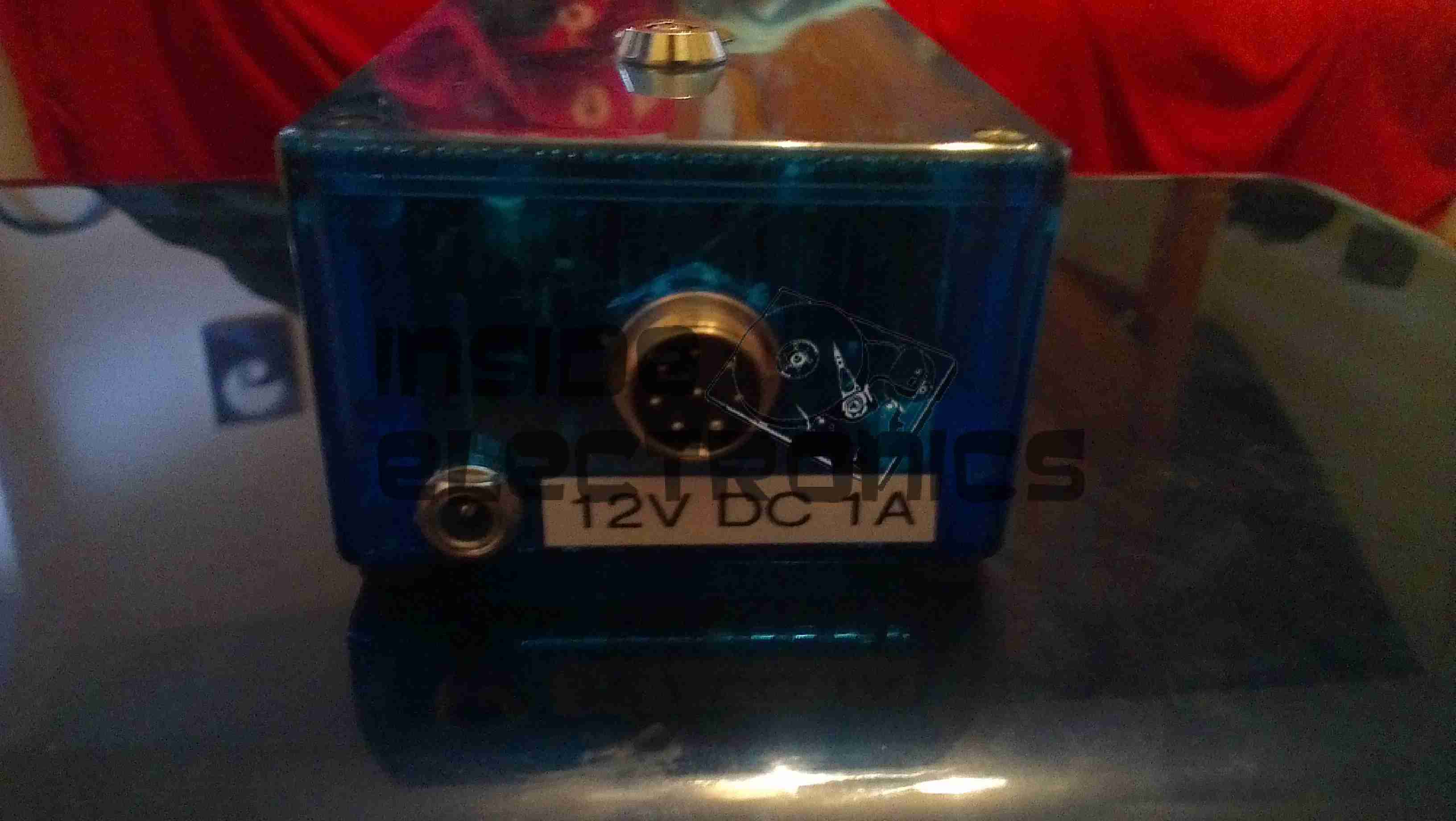
In preparation for my laser scanner project, I have modified my existing 445nm laser to accept a TTL blanking input. The laser driver is already enabled for this & just required an extra connection to interface with my laser scanner showboard. I have used an 8-pin connection to allow the same cable & interface to be used with an RGB laser system, when it arrives. The signals are as follows, from top centre, anti-clockwise:
Pin 1: +12v Power
Pin 2: Blue TTL
Pin3: GND
Pin 4: Green TTL
Pin 5: GND
Pin 6: Red TTL
Pin 7: GND
Centre: Power GND
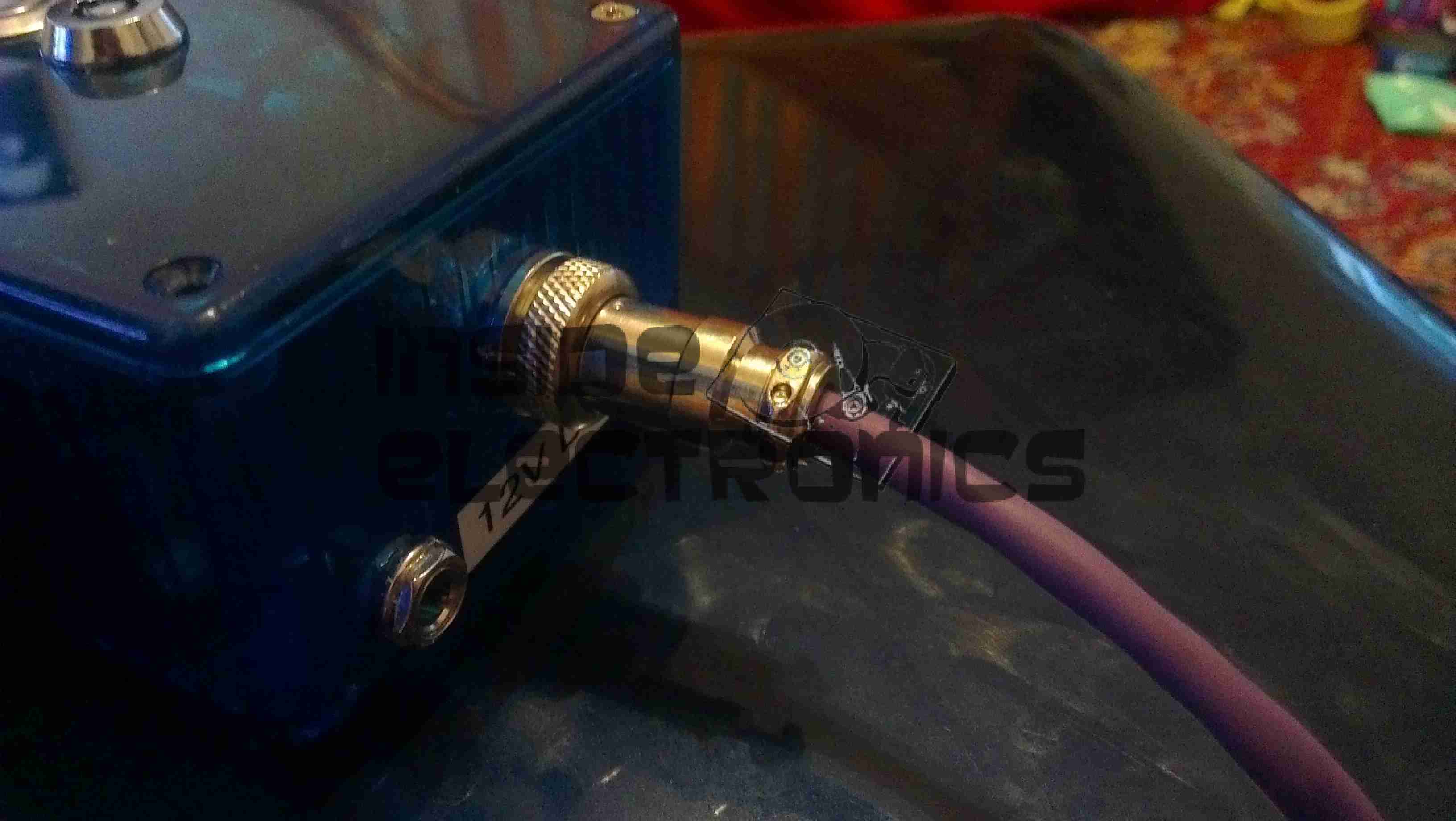
Custom TTL Cable
Here is the custom 8 core cable, which connects to the laser scanner show board. This cable allows the laser to be used for projection while still retaining the portable function & the keylock arming switch. When plugged in the cable bypasses the keyswitch & provides 12v DC direct to the laser driver.
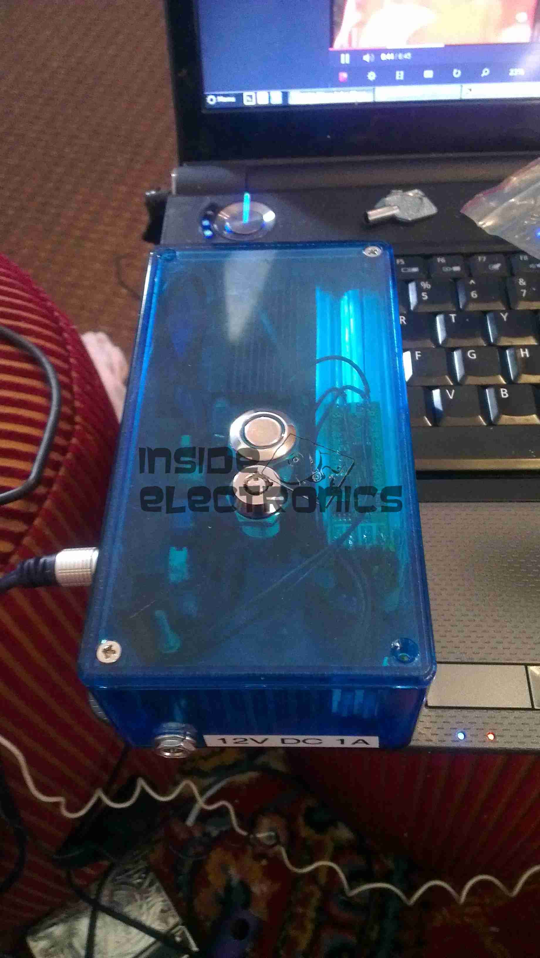
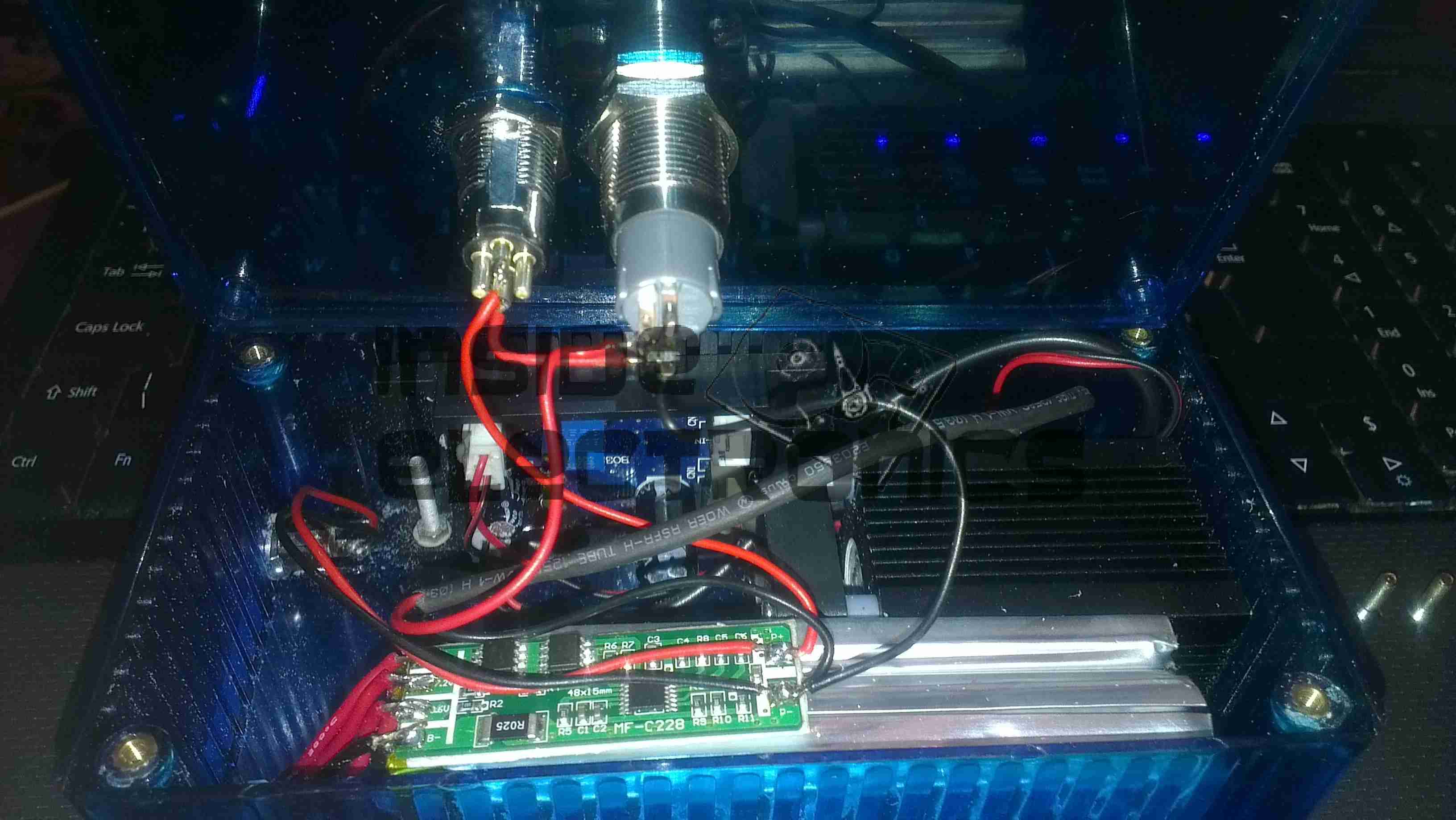
Here is a followup from the 1.5W laser module post.
The module has been fitted into a housing, with a 2.2Ah Li-Poly battery pack. Charging is accomplished with an external 12.6v DC power supply.
Above can be seen the pair of switches on the top, the keyswitch must be enabled for the laser to fire.
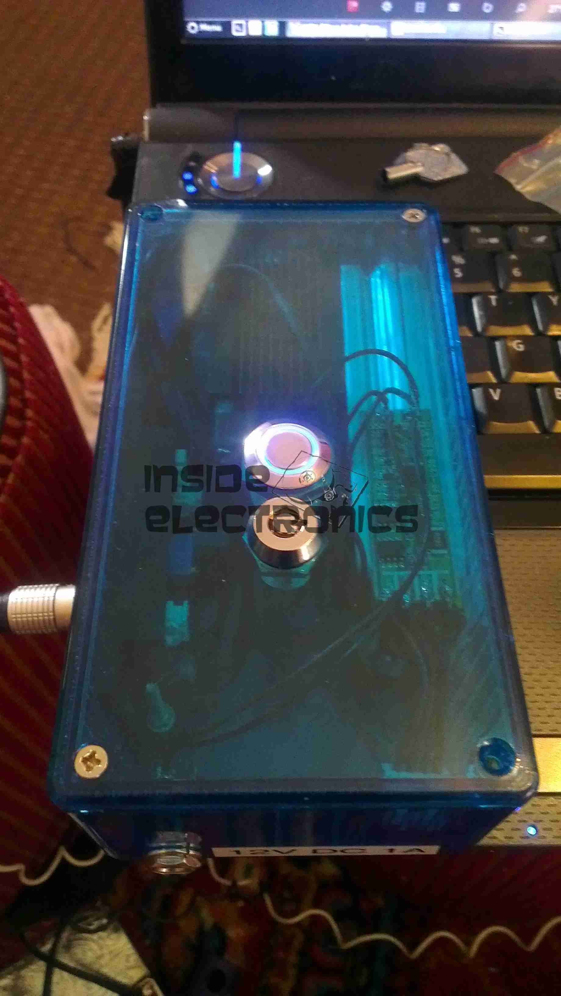
Armed
When armed, the ring around the push button illuminates blue, as a warning that the unit is armed.
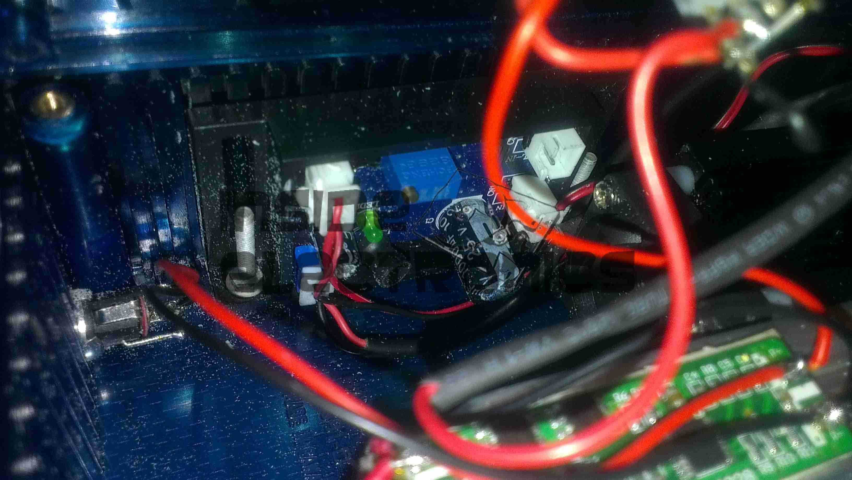
Switch Wiring
Inside the unit. The Li-Poly battery pack is at the bottom, with it’s protection & charging circuitry on the top. The switches are wired in series, with the LED connected to illuminate when the keyswitch is turned to the ON position.
Laser Driver
The push button applies power to the laser driver module, which regulates the input power to safely drive the semiconductor laser in the aluminium heatsink housing.
Here is an old chemical dosing system for industrial washing machines. These units are 4-pump models, with dual pumpheads. The motors are reversed to operate alternate pumps in the same head.
Label
From 2006, this is a fairly old unit, and made in the UK.
CPU Board
Main controller PCB, with interface to the power electronics via the ribbon cable, an external serial port for programming to it’s left. Powered by an ST microcontroller. The LCD is below this board.
PCU & Driver PCBs
Main power supply, sense input & motor driver boards. The PSU outputs +5v, +12v & +24v. The inputs on the lower left connect to the washing machine & trigger the pumps via the programming on the CPU. The motors are driven by L6202 H-Bridge drivers from ST.
Motor Assembly
Motor & gearbox assembly on the back of the pumphead. These are 24v DC units with 80RPM gearboxes.
UPDATE:
As it seems to be difficult to find, here is the user manual for this unit:
[download id=”5557″]
To help make my system more efficient, a pair of switching regulators has been fitted, the one shown above is a Texas Instruments PTN78060 switchmode regulator module, which provides a 7.5v rail from the main 12v battery pack.
A Lot like the LM317 & similar linear regulators, these modules require a single program resistor to set the output voltage, but are much more efficient, around the 94% mark at the settings used here.
The 7.5v rail supplies the LM317 constant current circuit in the laser diode driver subsection. This increases efficiency by taking some voltage drop away from the LM317.
5v Regulator
The 7.5v rail also provides power to this Texas Instruments PTH08000 switchmode regulator module, providing the 5v rail for the USB port power.
The parts arrived for my adjustable laser diode driver! Components here are an LM317K with heatsink, 100Ω 10-turn precision potentiometer, 15-turn counting dial & a 7-pin matching plug & socket.
Driver Schematic
Here is the schematic for the driver circuit. I have used a 7-pin socket for provisions for active cooling of bigger laser diodes. R1 sets the maximum current to the laser diode, while R2 is the power adjustment. This is all fed from the main 12v Ni-Cd pack built into the PSU. The LM317 is set up as a constant current source in this circuit.
Installed
Here the power adjust dial & the laser head connector have been installed in the front panel. Power is switched to the driver with the toggle switch to the right of the connector.
Regulator
The LM317 installed on the rear panel of the PSU with it’s heatsink.
Connection
Connections to the regulator, the output is fully isolated from the heatsink & rear panel.
This is detailing my portable multi-purpose power pack of my own design. Here is an overview, mainly showing the 4Ah 12v Ni-Cd battery pack.
Front Panel Right
Panel Features – Bottom: Car cigar lighter socket, main power keyswitch. Top: LED toggle switch, provision for upcoming laser project, Red main Power LED, 7A circuit breaker.
Front Panel Left
Top: Toggle switch serving post terminals, USB Port.
Post terminals supply unregulated 12v for external gadgets. USB port is standard 5v regulated for charging phones, PDAs etc.
Bottom: Pair of XLR connectors for external LED lights. Switches on their right control power & the knob controls brightness.
Additions are being made to this all the time, the latest being a 2W laser diode driver. Update to come soon!
Not strictly teardown related, but here is the Linux version of the RTL8187B WiFi chipset driver for all those who require it, it’s not available on the Realtek website:
Here is a Bosch 14.4v Professional cordless drill/driver, recovered from a skip!
It was thrown away due to a gearbox fault, which was easy to rectify.
Internals
Here is the drill with the side cover removed, showing it’s internal parts. The speed controller is below the motor & gearbox here. The unit at the top consists of a 12v DC motor, coupled to a 4-stage epicyclic gearbox unit, from which can be selected 2 different ratios, by way of the lever in the centre of the box. This disables one of the gear stages. There is a torque control clutch at the chuck end of the gearbox, this was faulty when found.
Motor
Here is the drive motor disconnected from the gearbox, having a bayonet fitting on the drive end.
Drive Gear
This is the primary drive gear of the motor, which connects with the gearbox.
Cooling Fan
The motor is cooled by this fan inside next to the commutator, drawing air over the windings.
Gearbox
This is the gearbox partially disassembled, showing the 1st & second stages of the geartrain. The second stage provides the 2 different drive ratios by having the annulus slide over the entire gearset, disabling it entirely, in high gear. The annulus gears are a potential weak point in this gearbox, as they are made from plastic, with all other gears being made of steel.
Charger
Here is the charging unit for the Ni-Cd battery packs supplied with the drill. The only indicator is the LED shown here on the front of the unit, which flashes while charging, & comes on solid when charging is complete. Charge termination is by way of temperature monitoring.
Transformer
Here the bottom of the charger has been removed, showing the internal parts. An 18v transformer supplies power to the charger PCB on the left.
Charger PCB
This is the charger PCB, with a ST Microelectronics controller IC marked 6HKB07501758. I cannot find any information about this chip.
Battery Pack Internals
Here is a battery pack with the top removed, showing the cells.
Temperature Sensor
This is the temperature sensor embedded inside the battery pack that is used by the charger to determine when charging is complete.
An ICL barcode scanner from the 80s is shown here. This is the top of the unit with cover on.
Cover Removed
Plastic cover removed from the unit showing internal components. Main PSU on left, scan assembly in center. Laser PSU & Cooling fan on right. Laser tube at top.
Scan Motor
Closeup of laser scan motor. This unit scans the laser beam rapidly across the glass plate to read the barcode.
Controller PCB
View of the bottom of the unit, showing the controller PCB in the centre.
Scan Motor Driver
The 3-phase motor driver circuit for the scan motor. 15v DC powered.
Laser Unit
This is the laser unit disconnected from the back of the scanner. HT PSU is on right hand side, beam emerges from optics on left.
Laser Unit Label
This unit is date stamped 1987. The oldest laser unit i own.
If you’ve found my content useful, please consider leaving a donation by clicking the Tip Jar below!
All collected funds go towards new content & the costs of keeping the server online.