Posted on 5 Comments

Jaguar S-Type Aux Heater / Webasto Thermo Top V Part 1 – Teardown & Cleaning

Jag Label
Jag Label

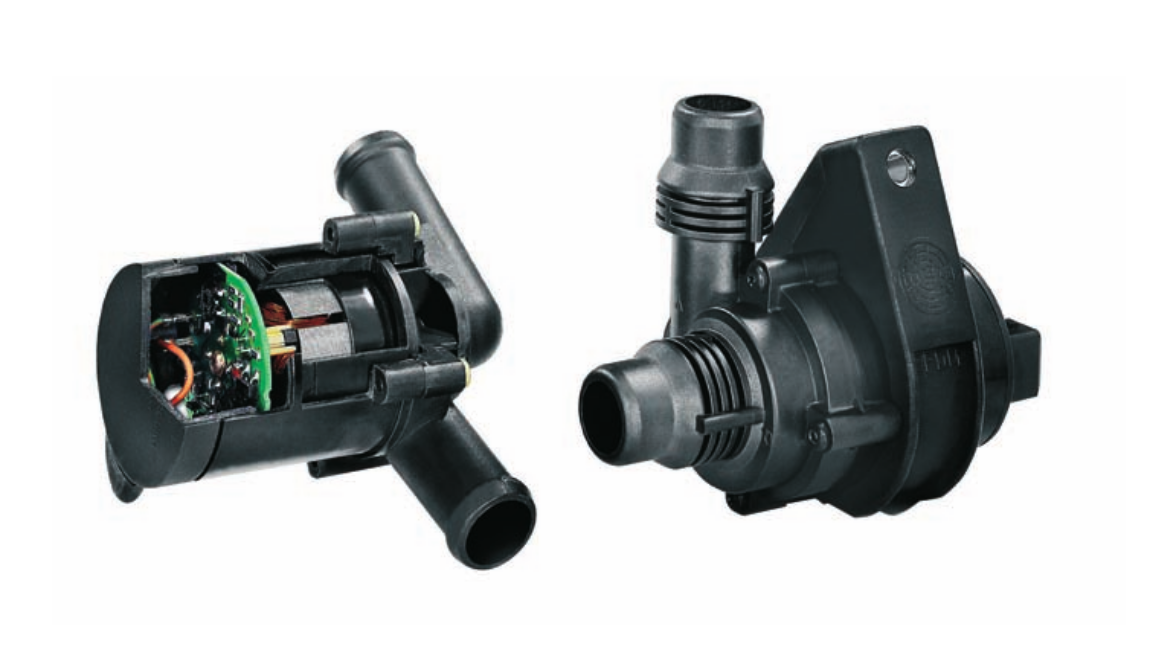
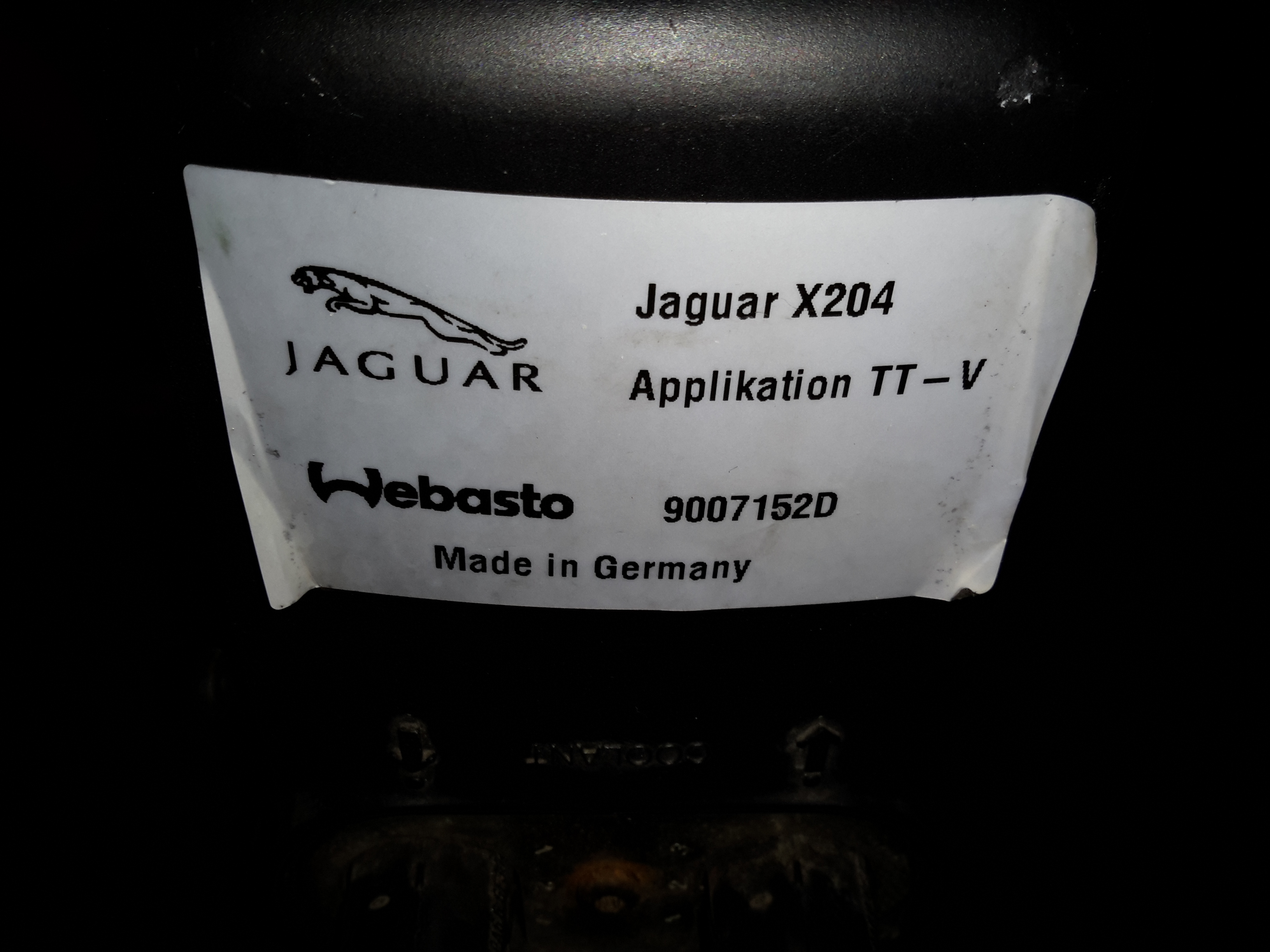
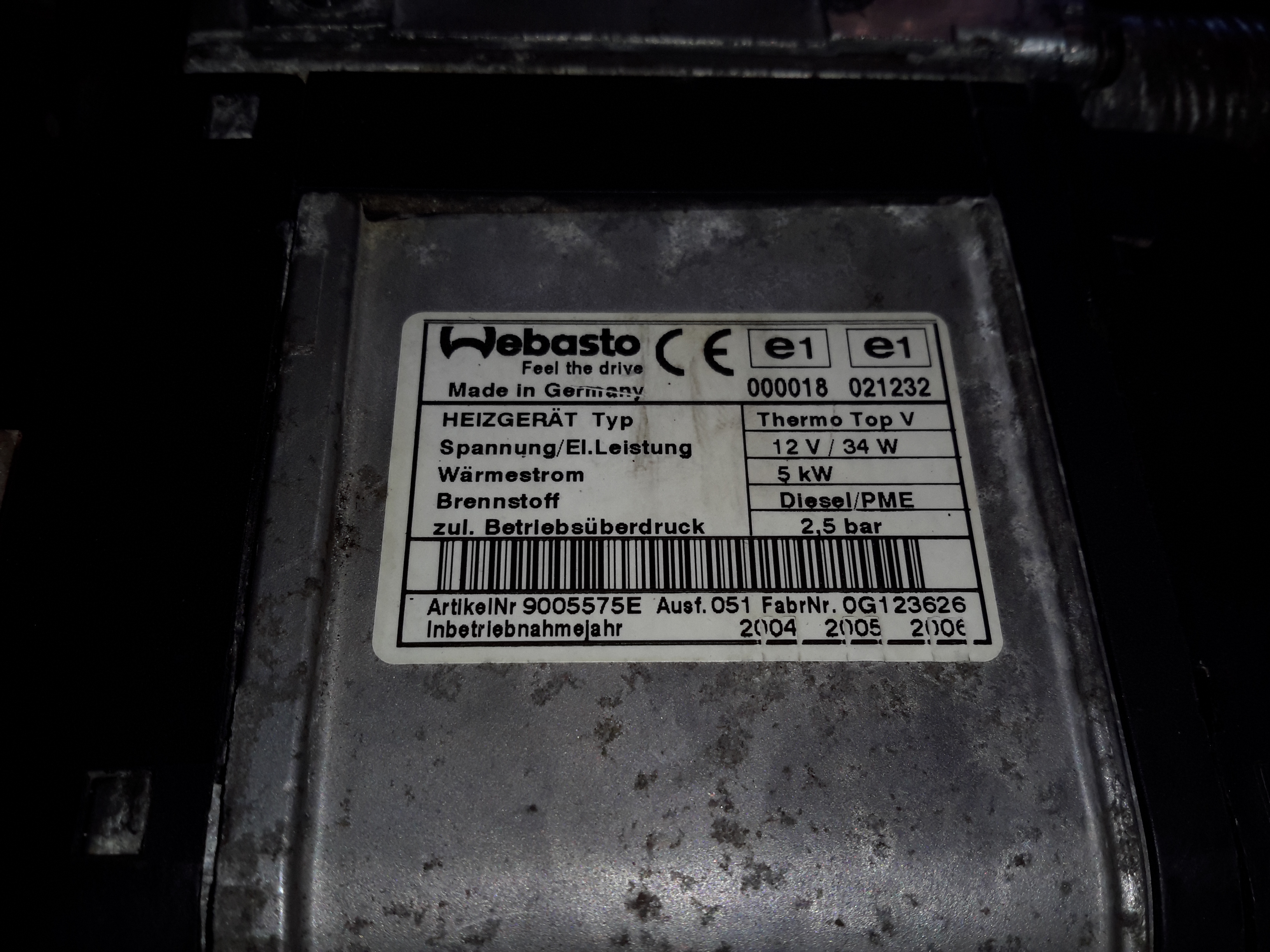
Here’s another Diesel-fired heater related project – these Webasto heaters are fitted to Jaguar S-Type cars as auxiliary heaters, since (according to the Jag manual), the modern fuel-efficient diesels produce so little waste heat that extra help is required to run the car’s climate control system. (Although this seems to nullify any fuel efficiency boost, as the fuel saved by not producing so much waste heat in the engine itself is burned in an aux heater to provide heat anyway). The unfortunate part is these units don’t respond to applying +12v to Pin 1 of the ECU to get them to start – they are programmed to respond to CAN Bus & K-Line Bus only, so they require a bit more effort to get going. They also don’t have a built-in water circulation pump unlike the Webasto Thermo Top C heaters – they expect the water flow to be taken care of by the engine’s coolant pump.

Webasto Label
Webasto Label
Water Side
Water Side

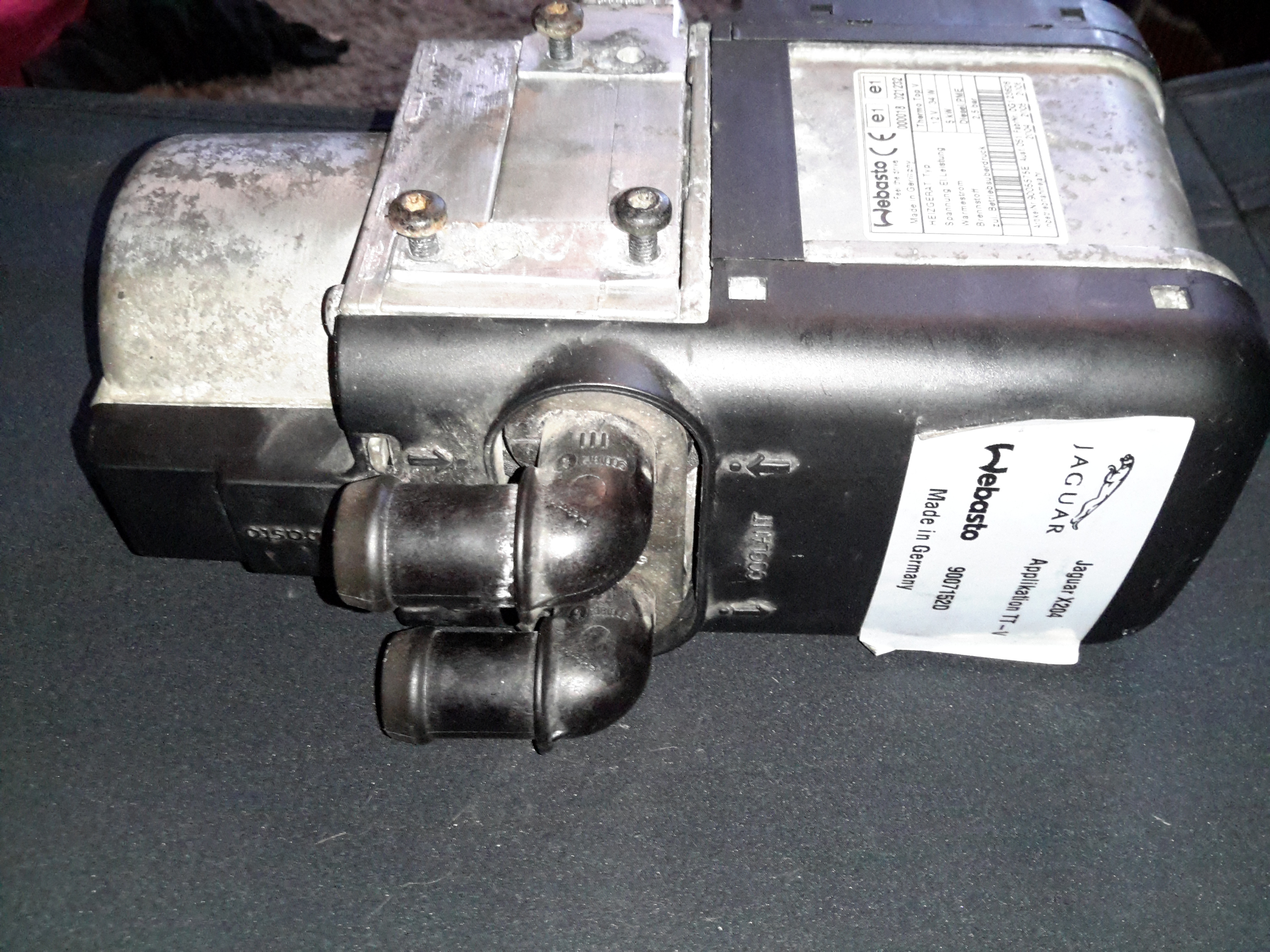
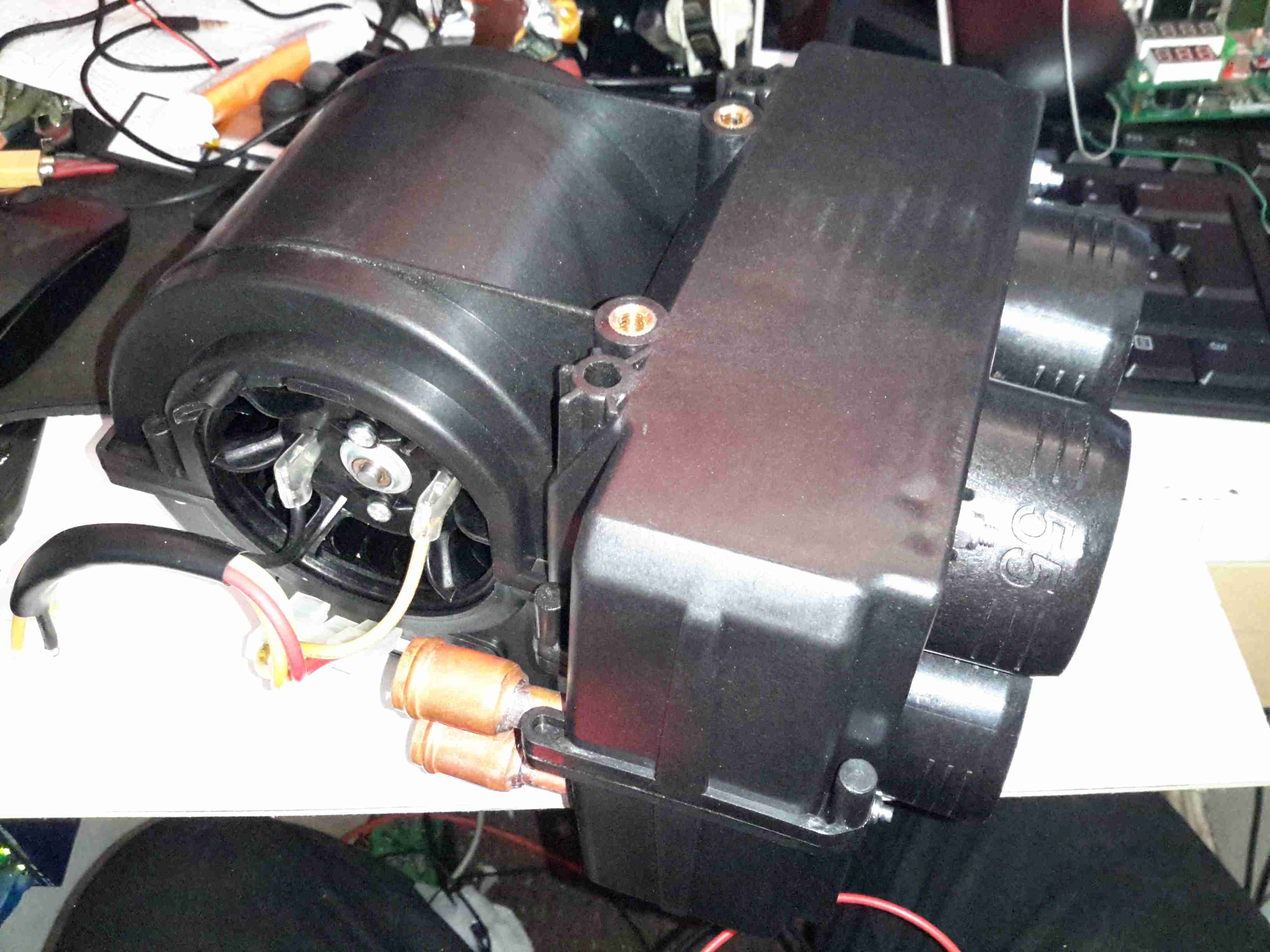
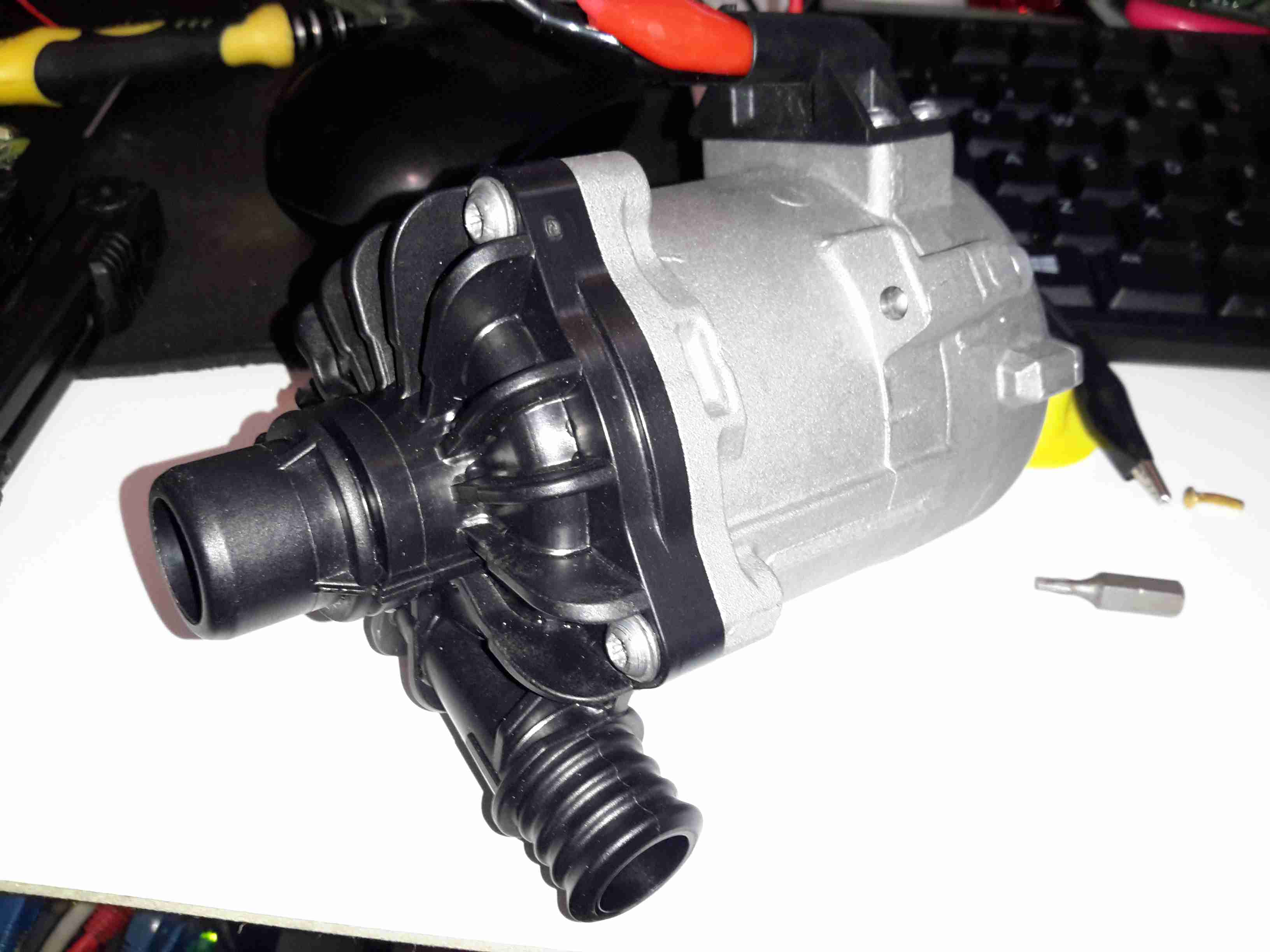
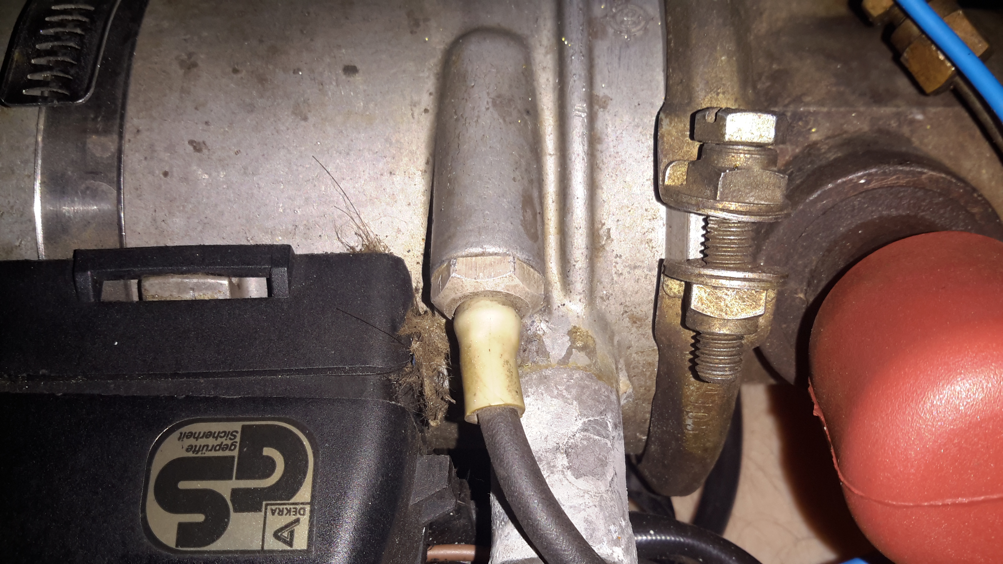
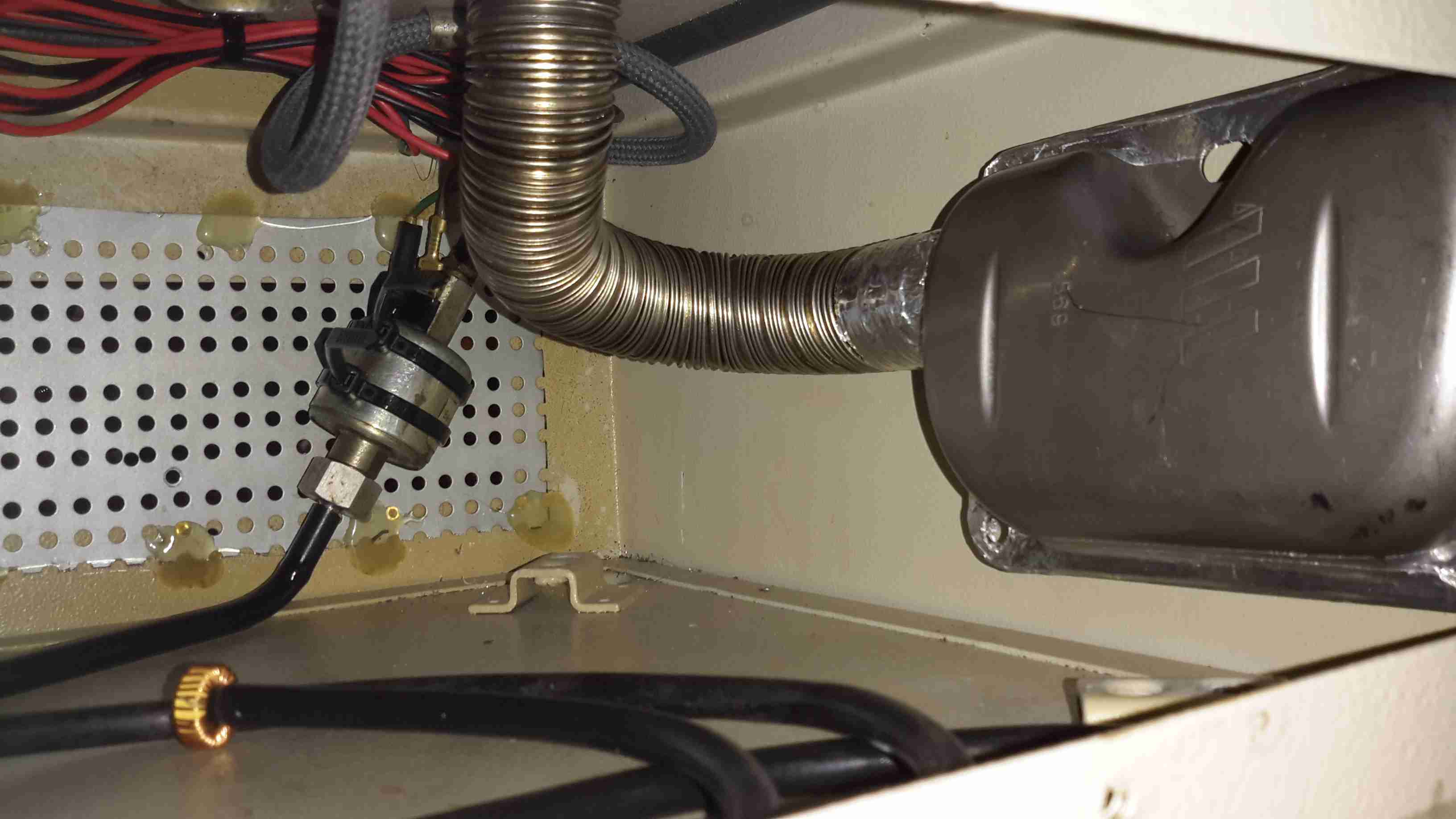
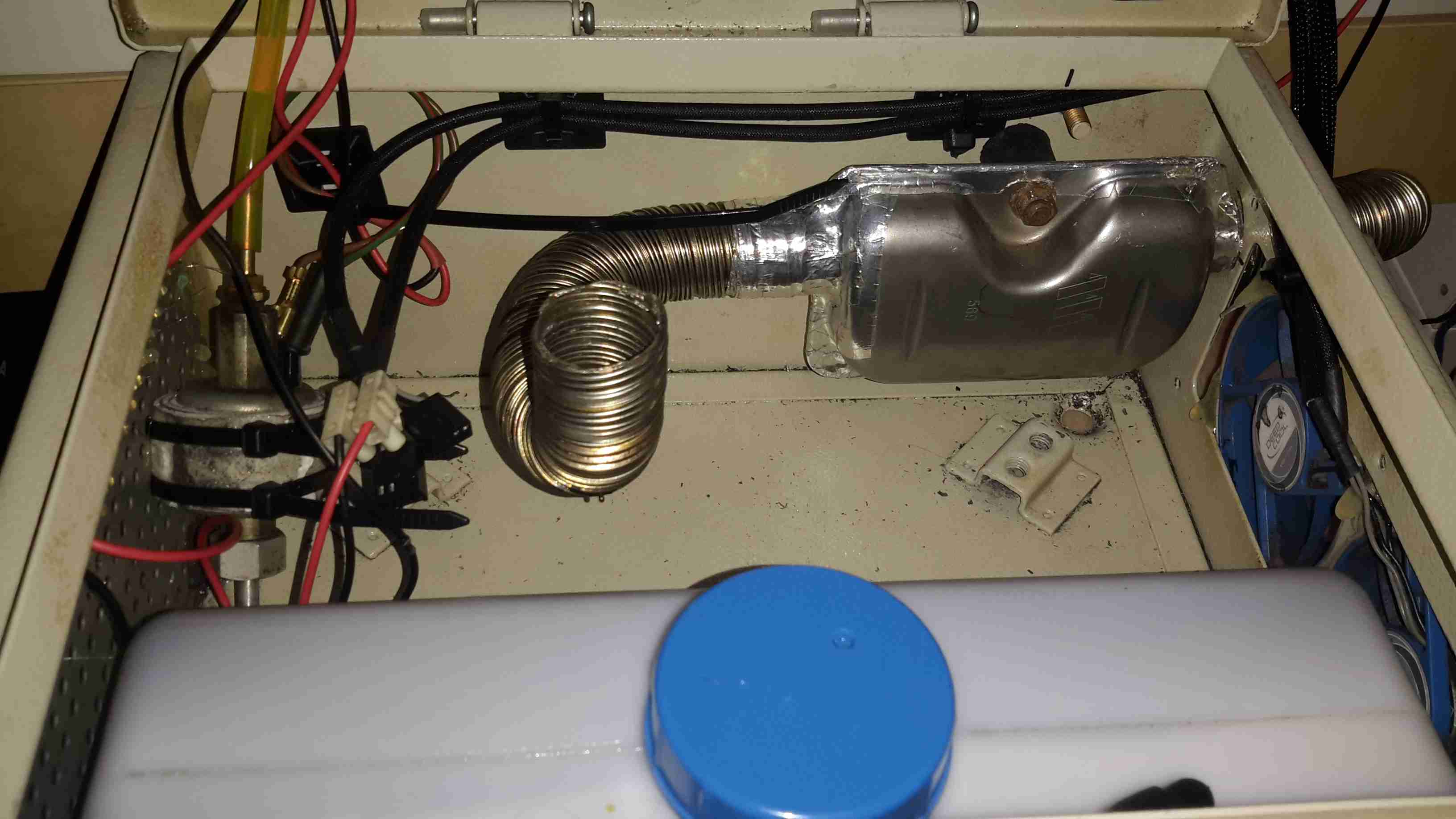
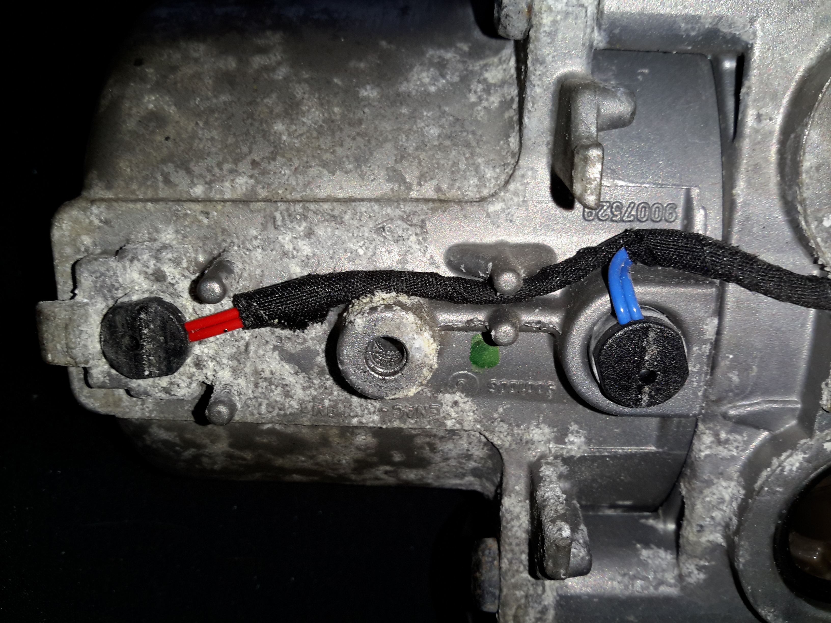
The water ports are on the side of this heater instead of the end, the heat exhanger is on the left. These hearers are fitted to the car under the left front wing, behind a splash guard. Pretty easy to get to but they get exposed to all the road dirt, water & salt so corrosion is a little problem. The fuel dosing pump is in a much more difficult spot to get at – it’s under the car next to the fuel tank on the right hand side. Access to the underside with stands is required to get at this.

ECU Side
ECU Side

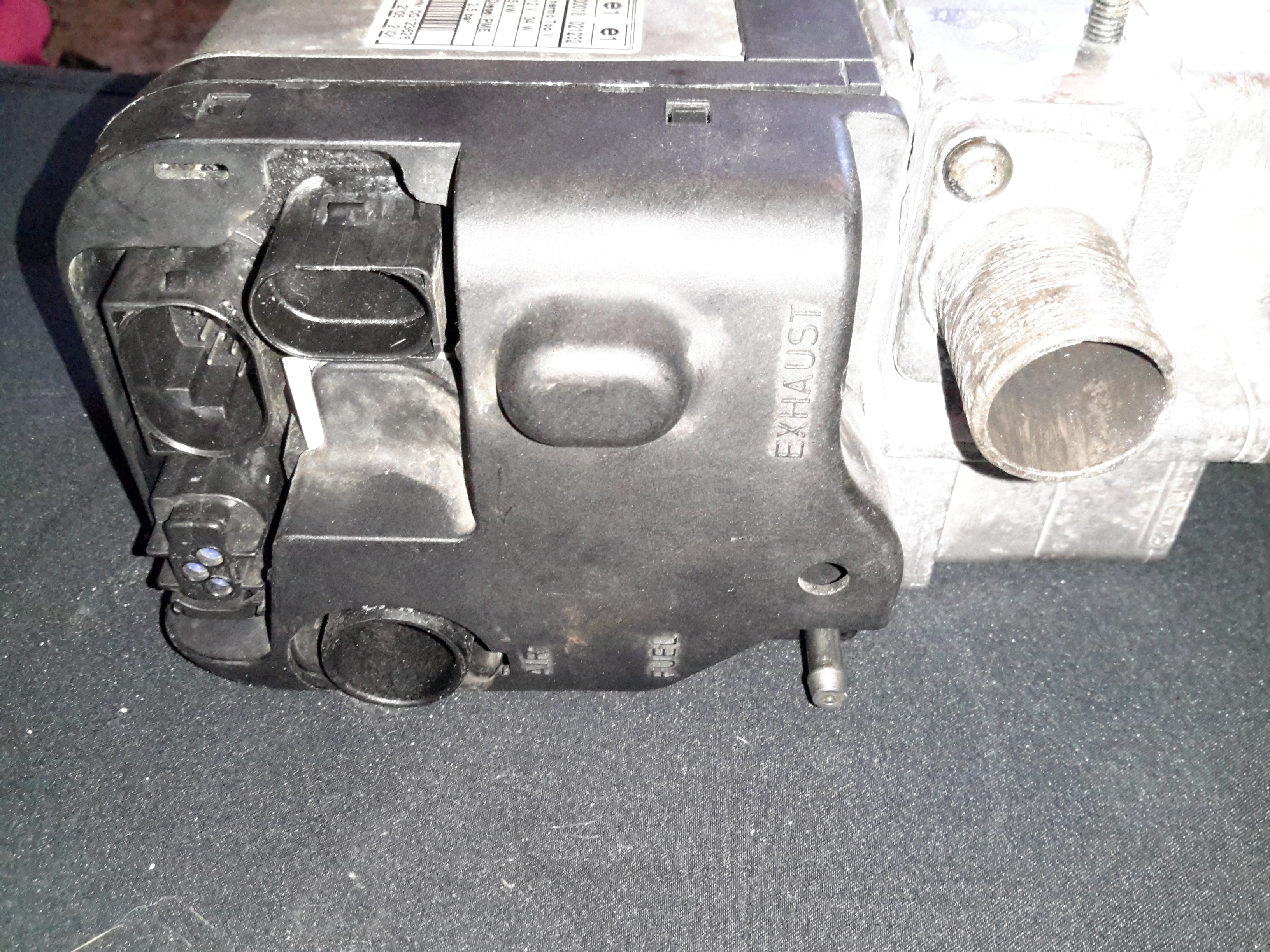
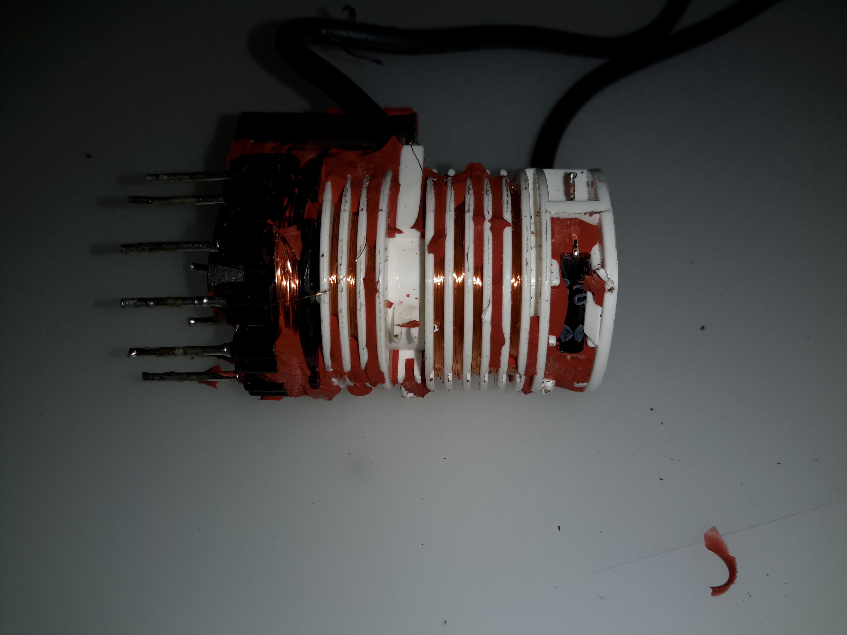
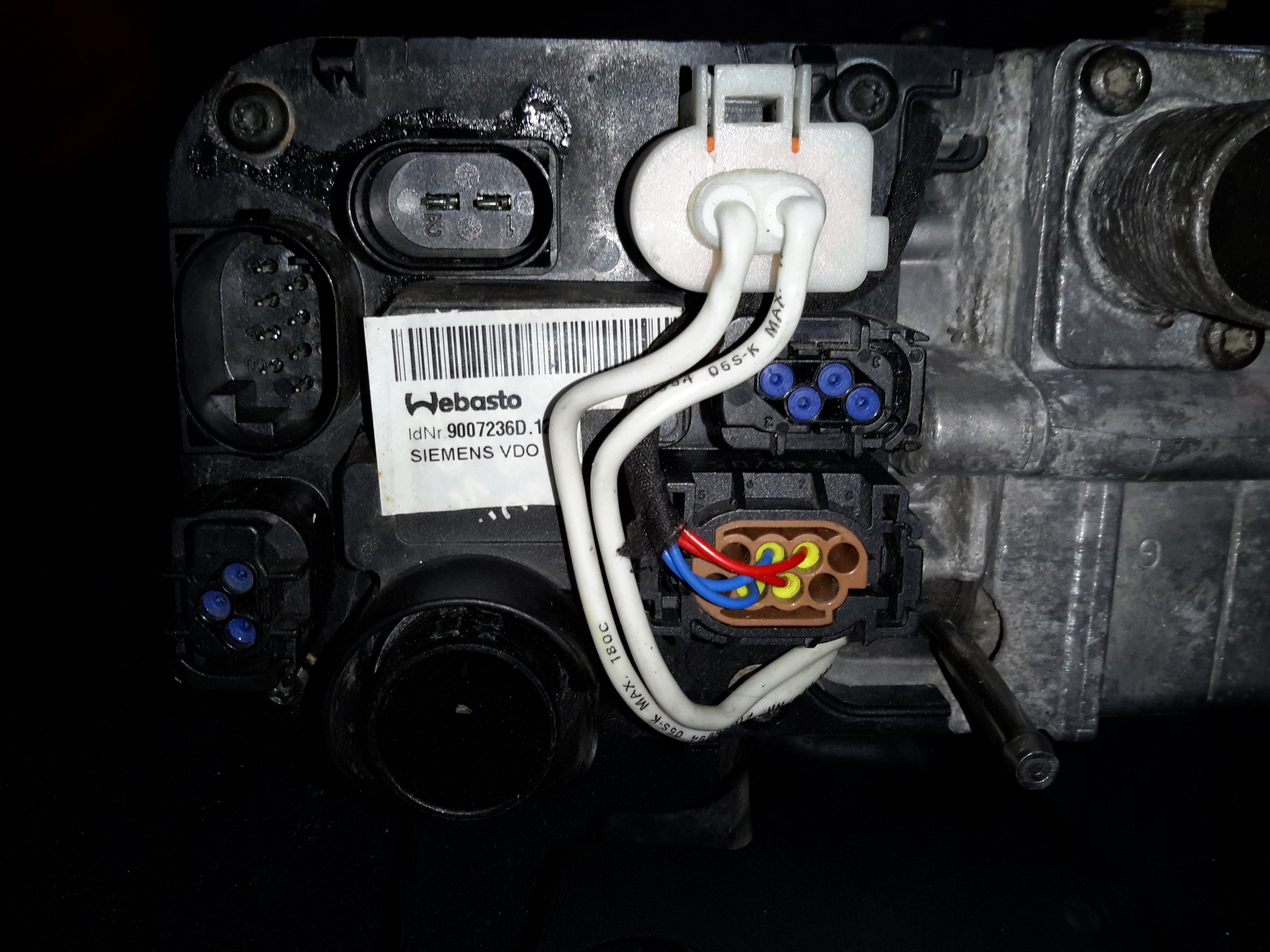
The ECU side has all the other connections – Combustion air, exhaust, fuel, power & control.

External Connectors
External Connectors

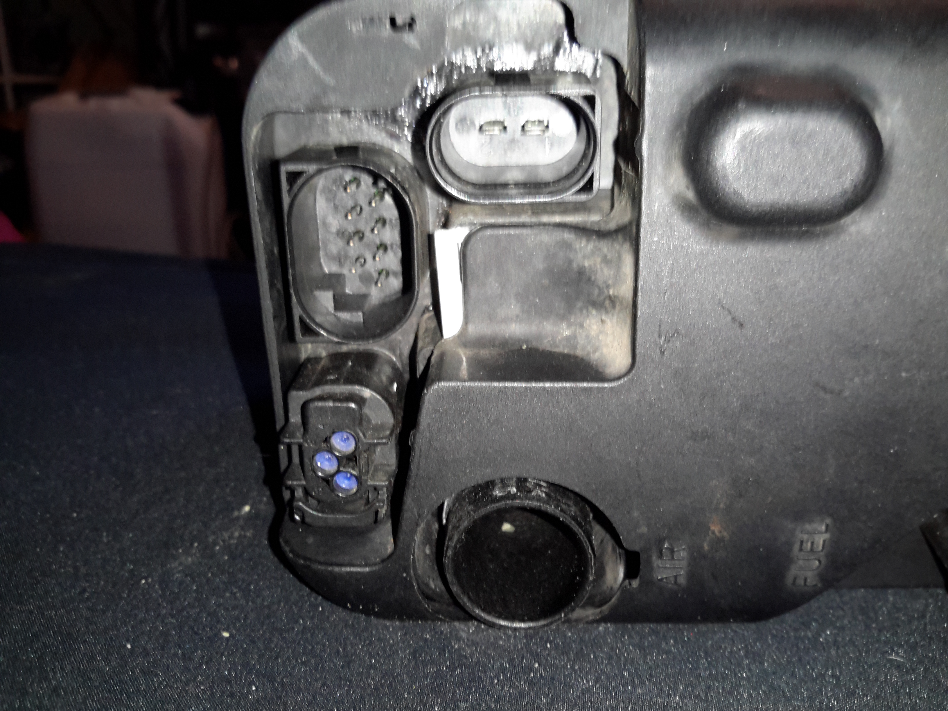
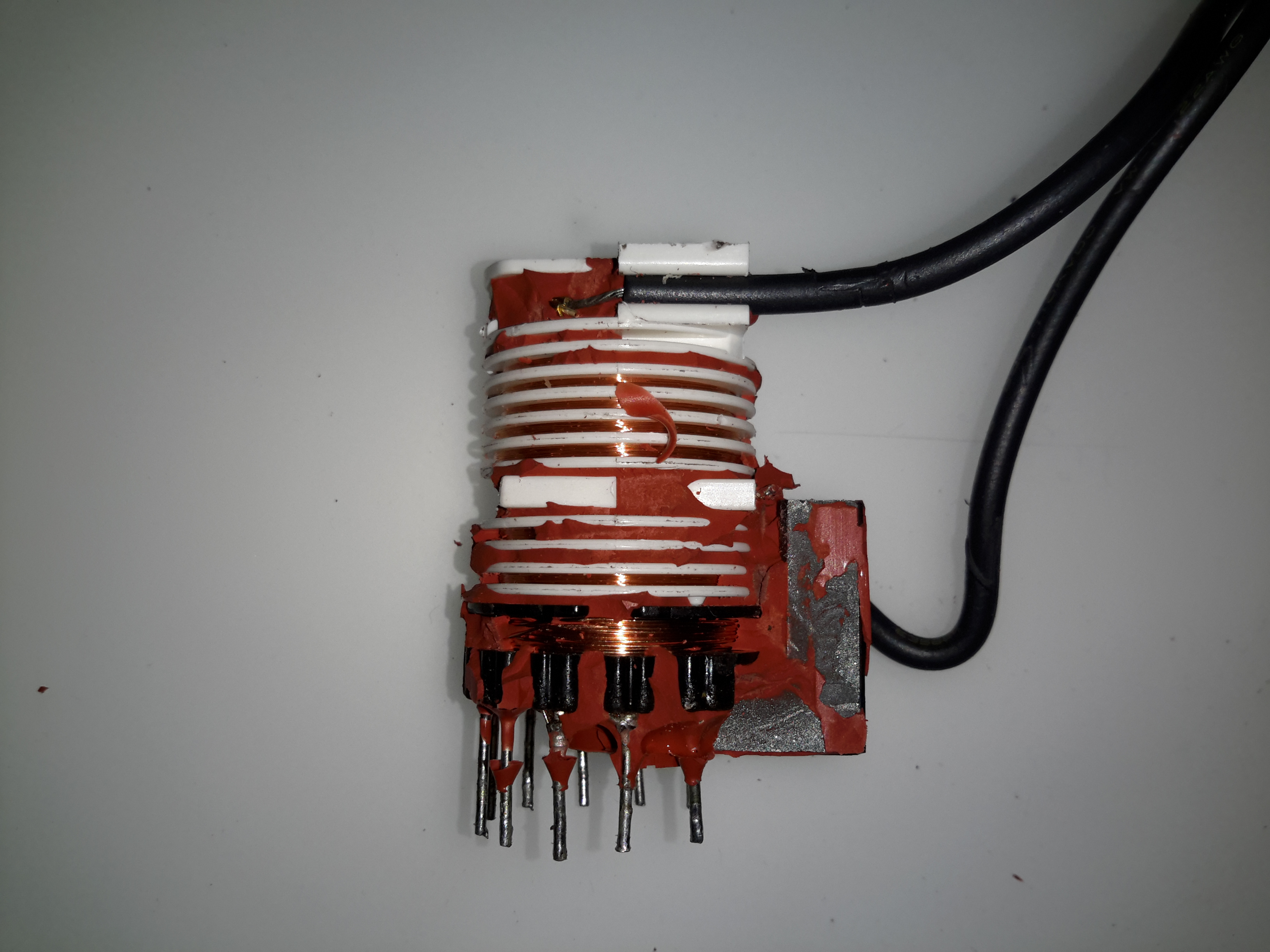
Only two of the external connectors are used on these heaters, the large two pin one is for main power – heavy cable required here as the current draw can climb to ~30A on startup while the glow plug fires. The 8-pin connector on the left is the control connector, where the CAN / K-Line / W-Bus buses live. The fuel dosing pump is also supplied from a pin on this connector. The small 3-pin under that is a blank for a circulation pump where fitted. Pinouts are here:

PinSignal
1Battery Positive
2Battery Negative
Pin NumberSignalNotes
1Telestart / Heater EnableWould usually start the heater with a simple +12v ON signal, but is disabled in these heaters.
2W-Bus / K-LineDiagnostic Serial Bus Or Webasto Type 1533 Programmer / Clock
3External Temp Sensor
4CAN-CAN Bus Low
5Fuel Dosing PumpFuel Pump output. Connect pump to this pin & ground. Polarity unimportant.
6Solenoid ValveFuel cutoff solenoid optionally fitted here.
7CAN+CAN Bus High
8Cabin Heater Fan ControlThis output switches on when heater reaches +50°C to control car heater blower
PinSignalNotes
1??
2Circulation Pump +
3Circulation Pump -
ECU Cover Removed
ECU Cover Removed

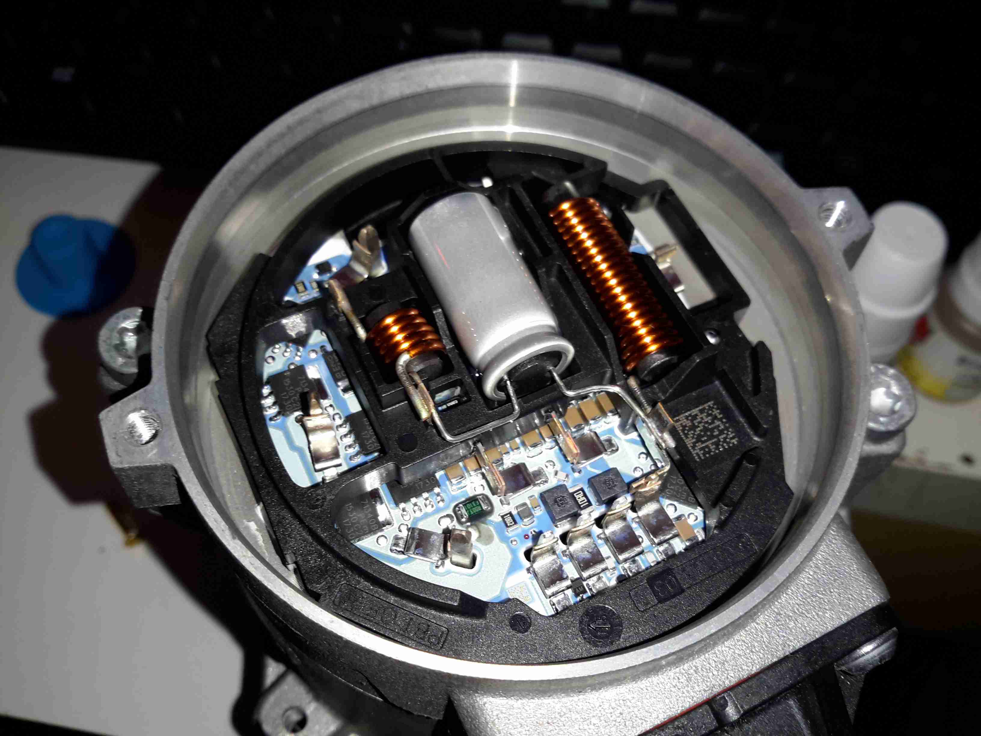
Removing the clipped-on plastic cover reveals the other ECU connectors. The large white one feeds the glow plug, & the large multi-pin below brings in the temp & overheat sensor signals.

MC9S12DT128B Microcontroller

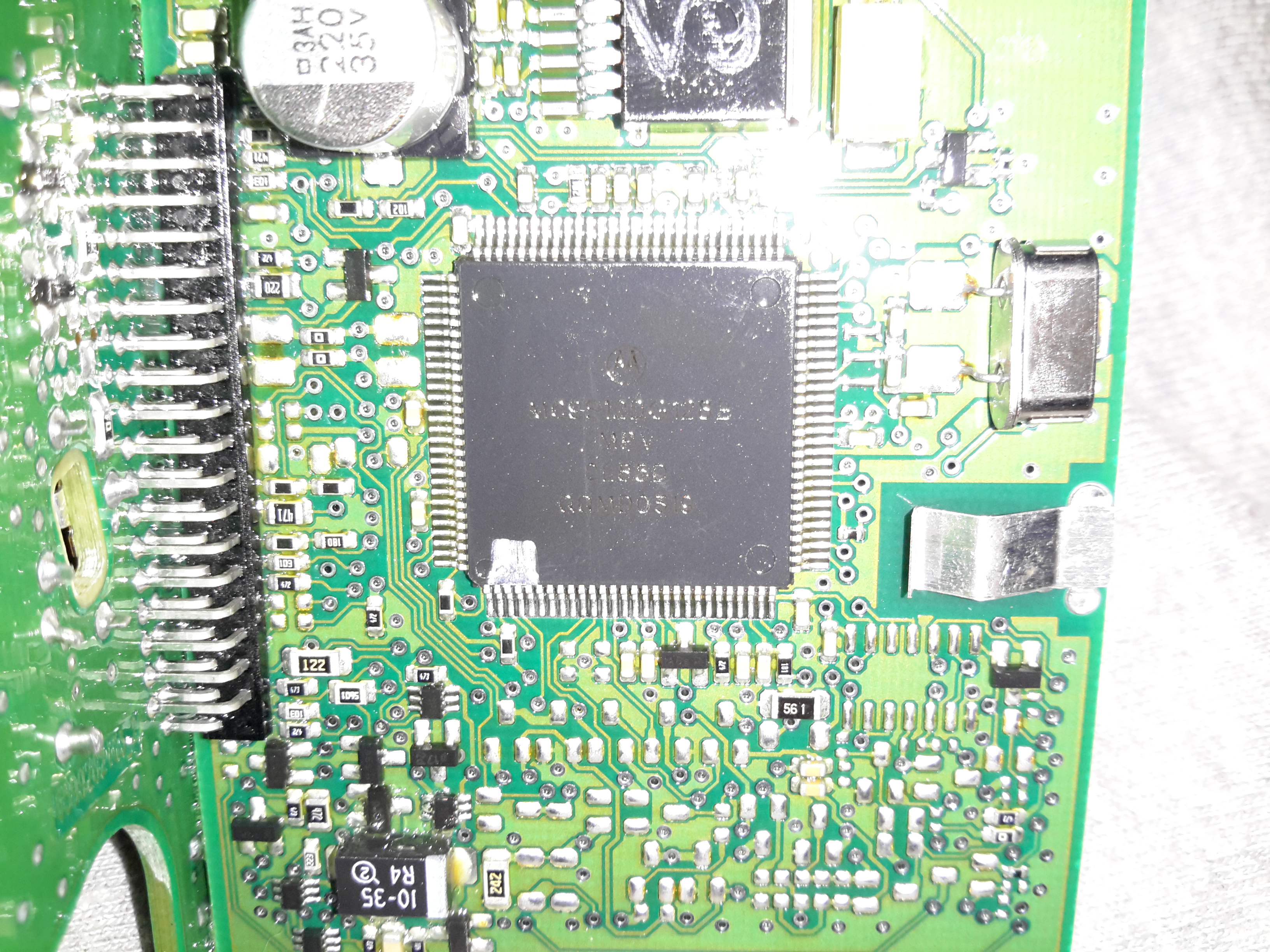
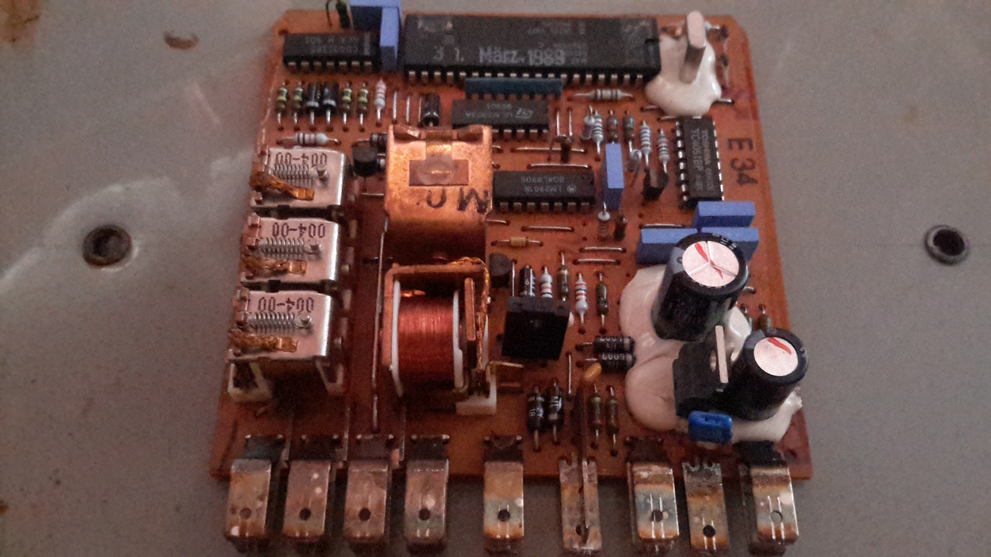
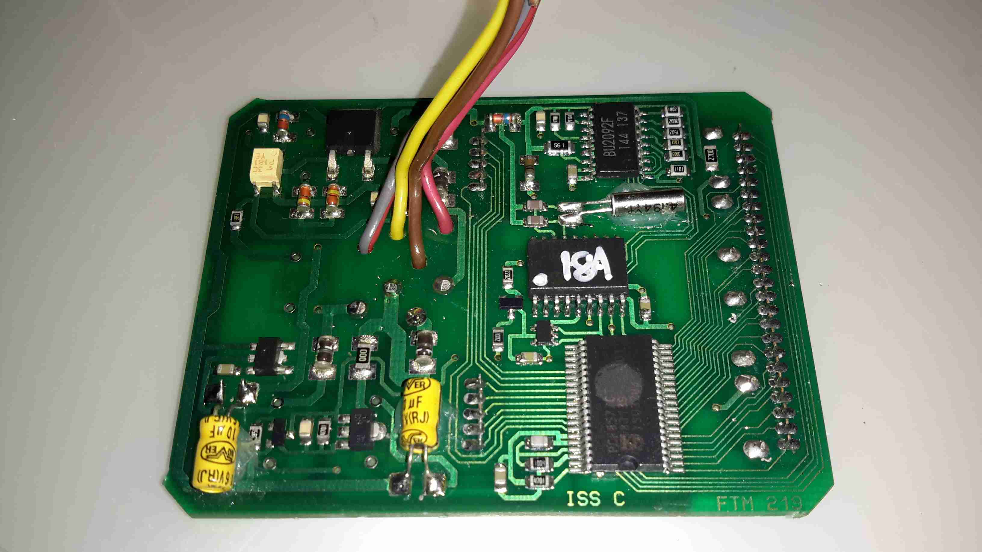
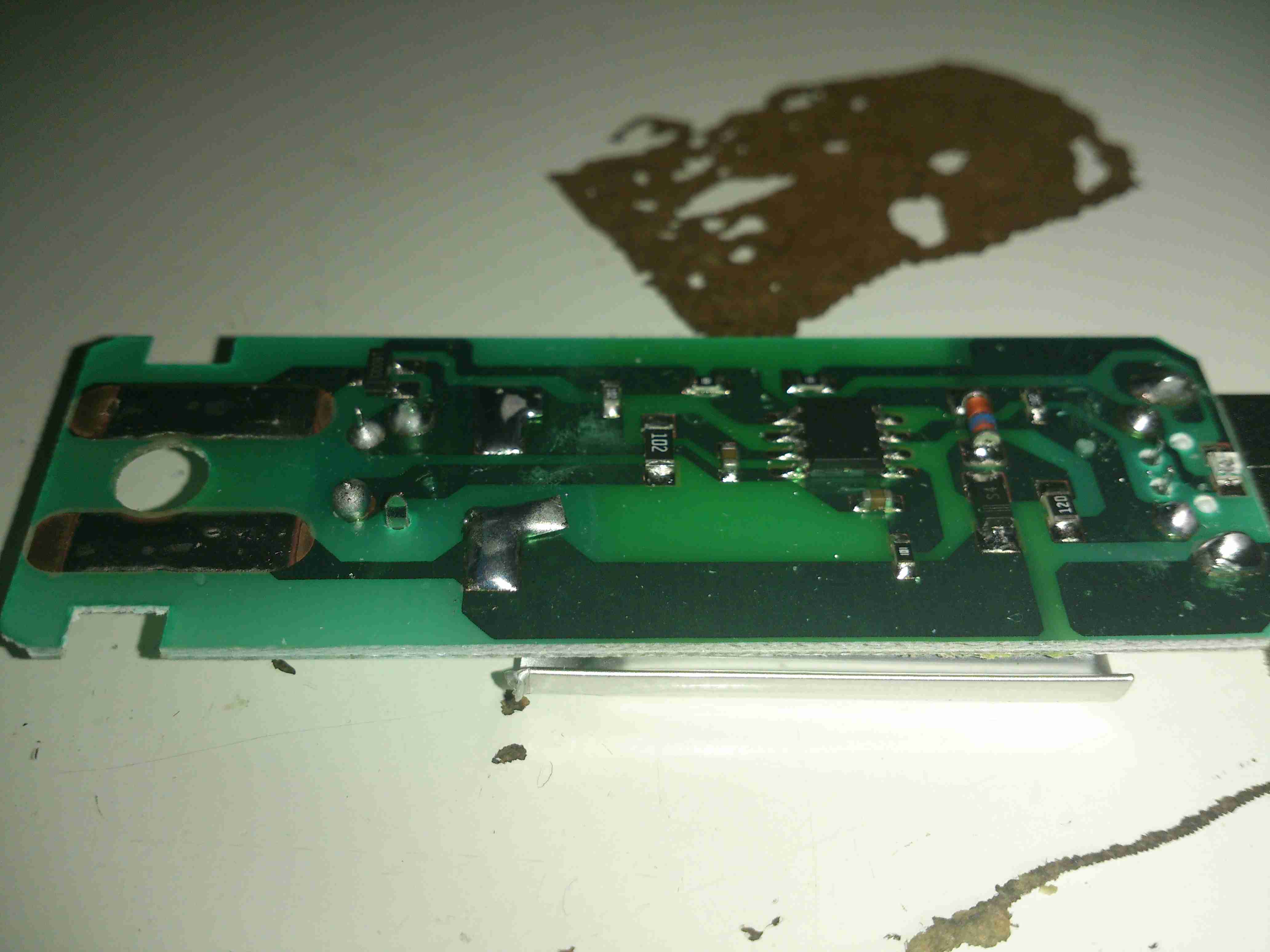
The heart of the ECU is a massive microcontroller, a Freescale MC9S12DT128B, attached to a daughterboard hooked into the ECU power board.

Power Section
Power Section

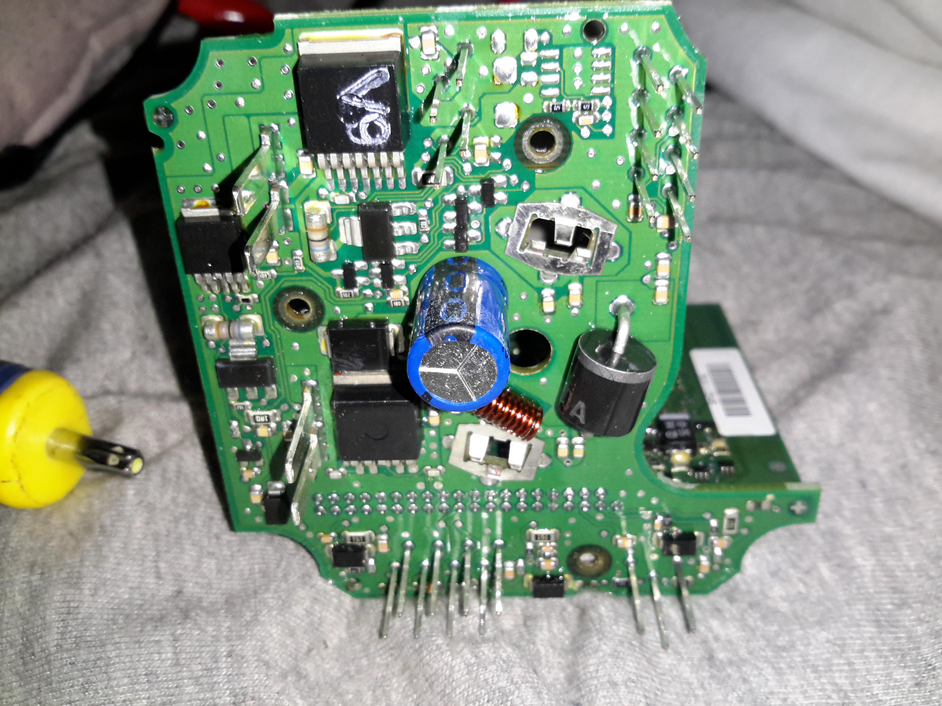
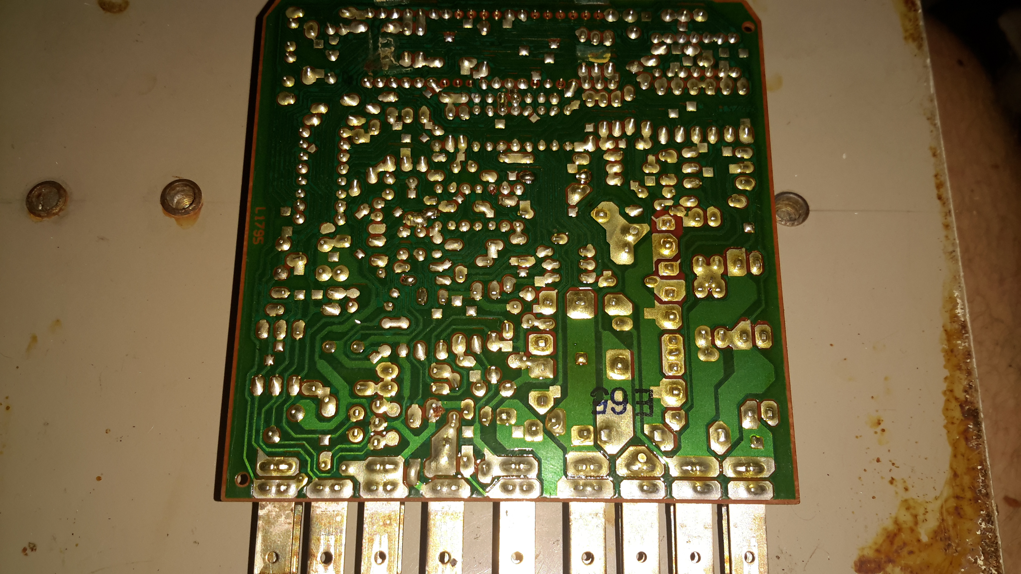
The high power section is on the board just under the connectors, here all the large semiconductors live for switching the fan motor, glow plug, external loads, etc.

LIN & CAN Bus Transceivers

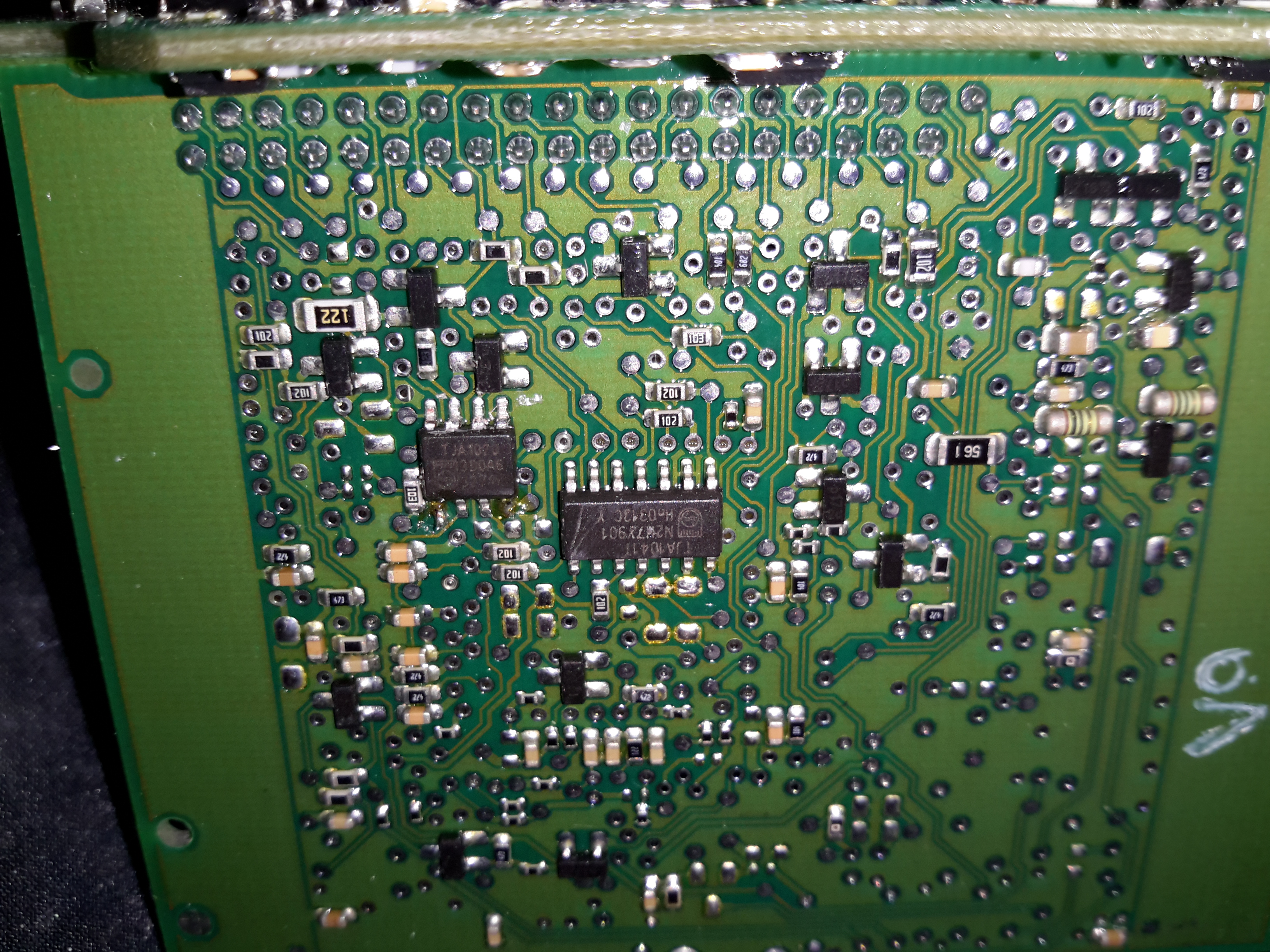
The bus transceivers are separate ICs on the control board, a TJA1041 takes care of the CAN bus. There’s also a TJA1020 LIN bus transceiver here, which is confusing since none of the Webasto documentation mentions LIN bus control.

Combustion Fan Motor

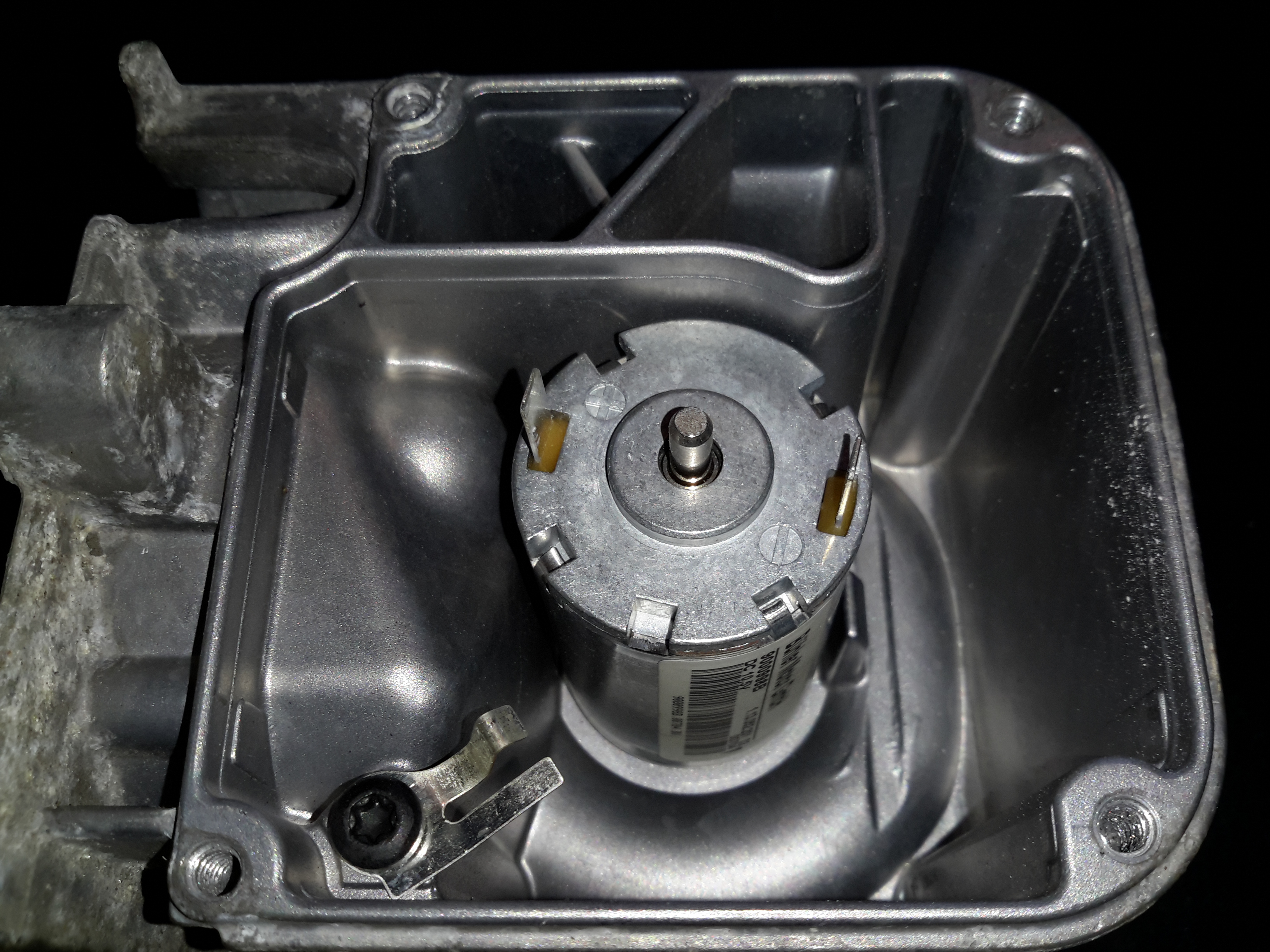
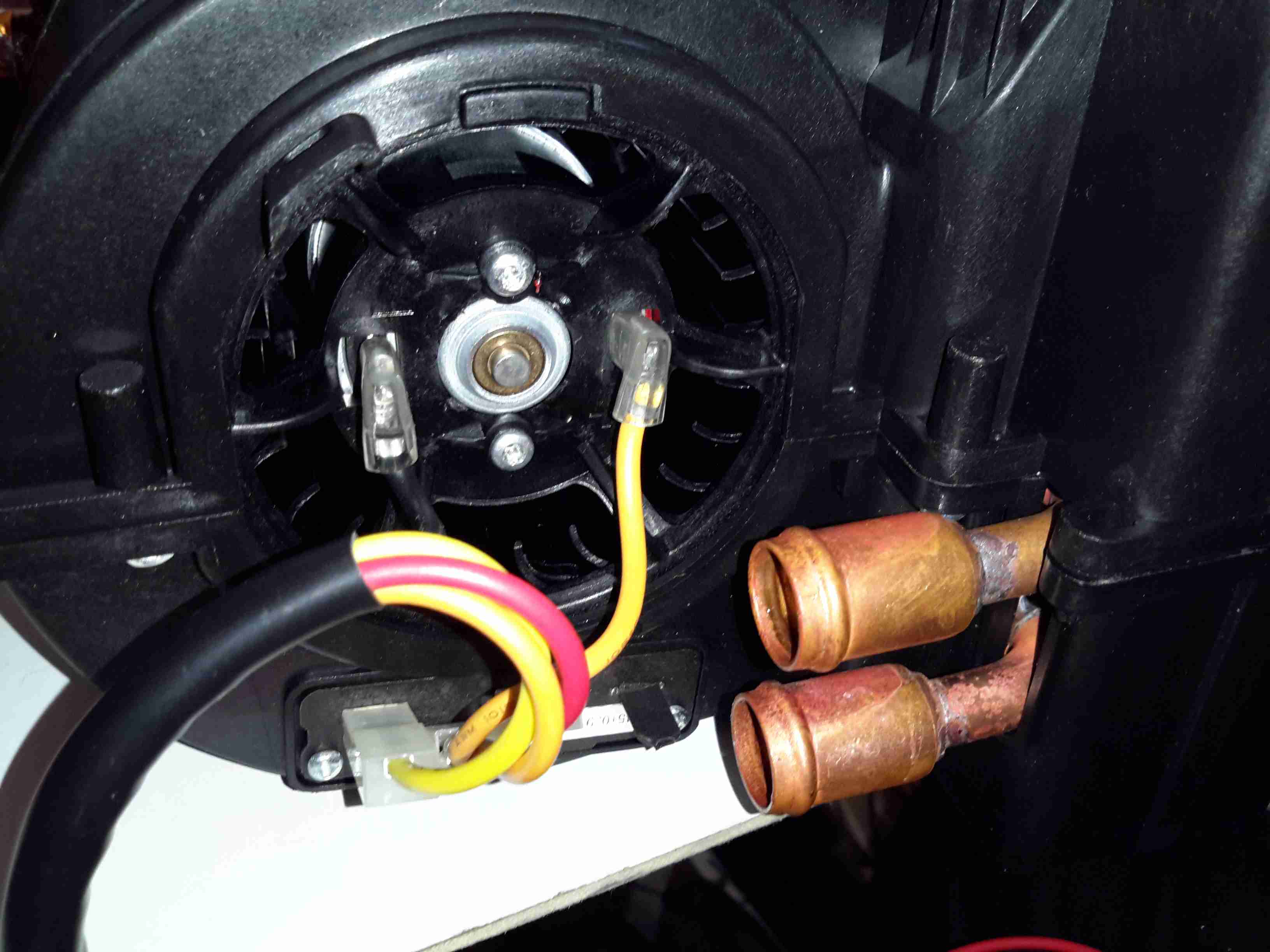
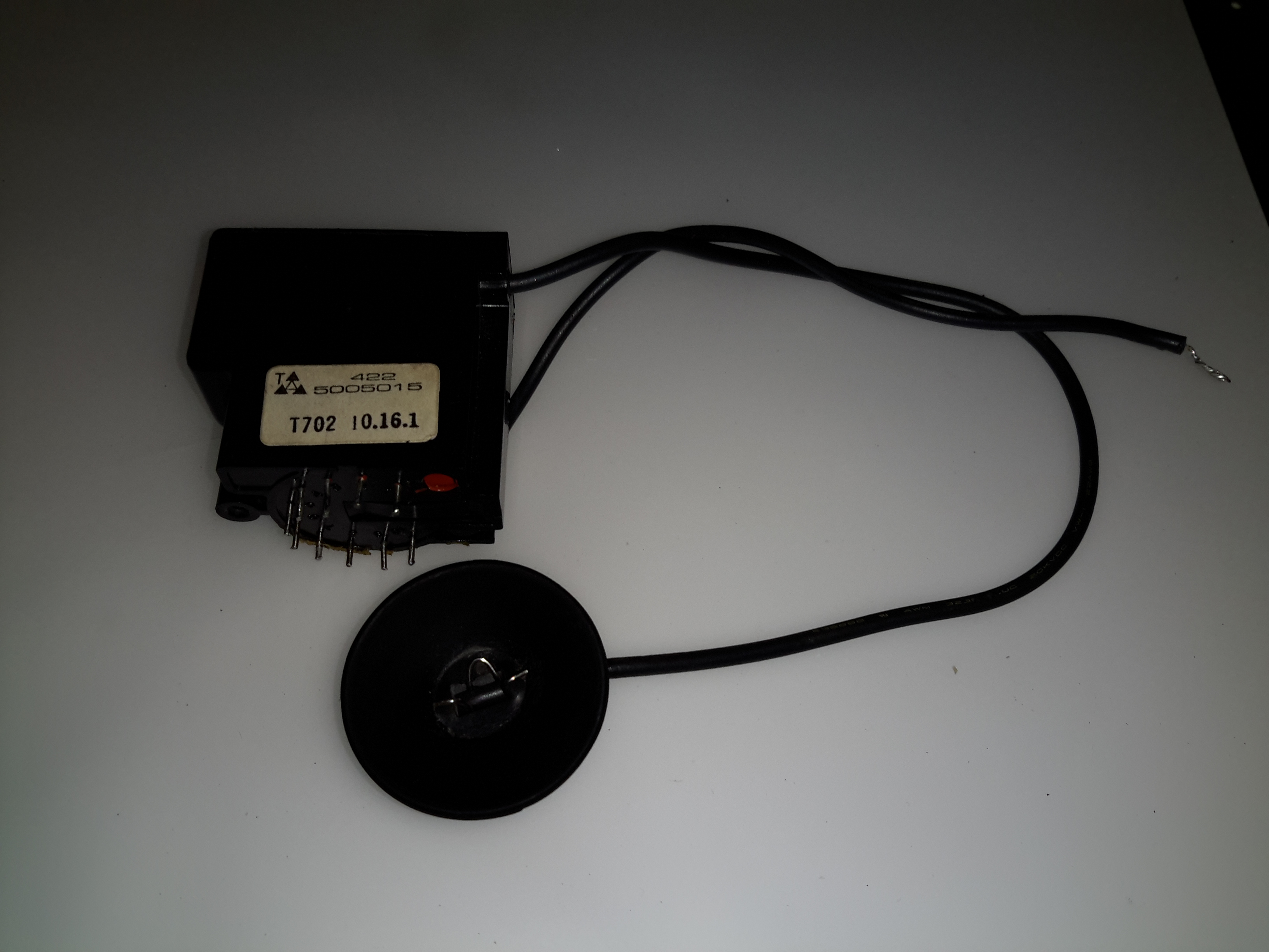
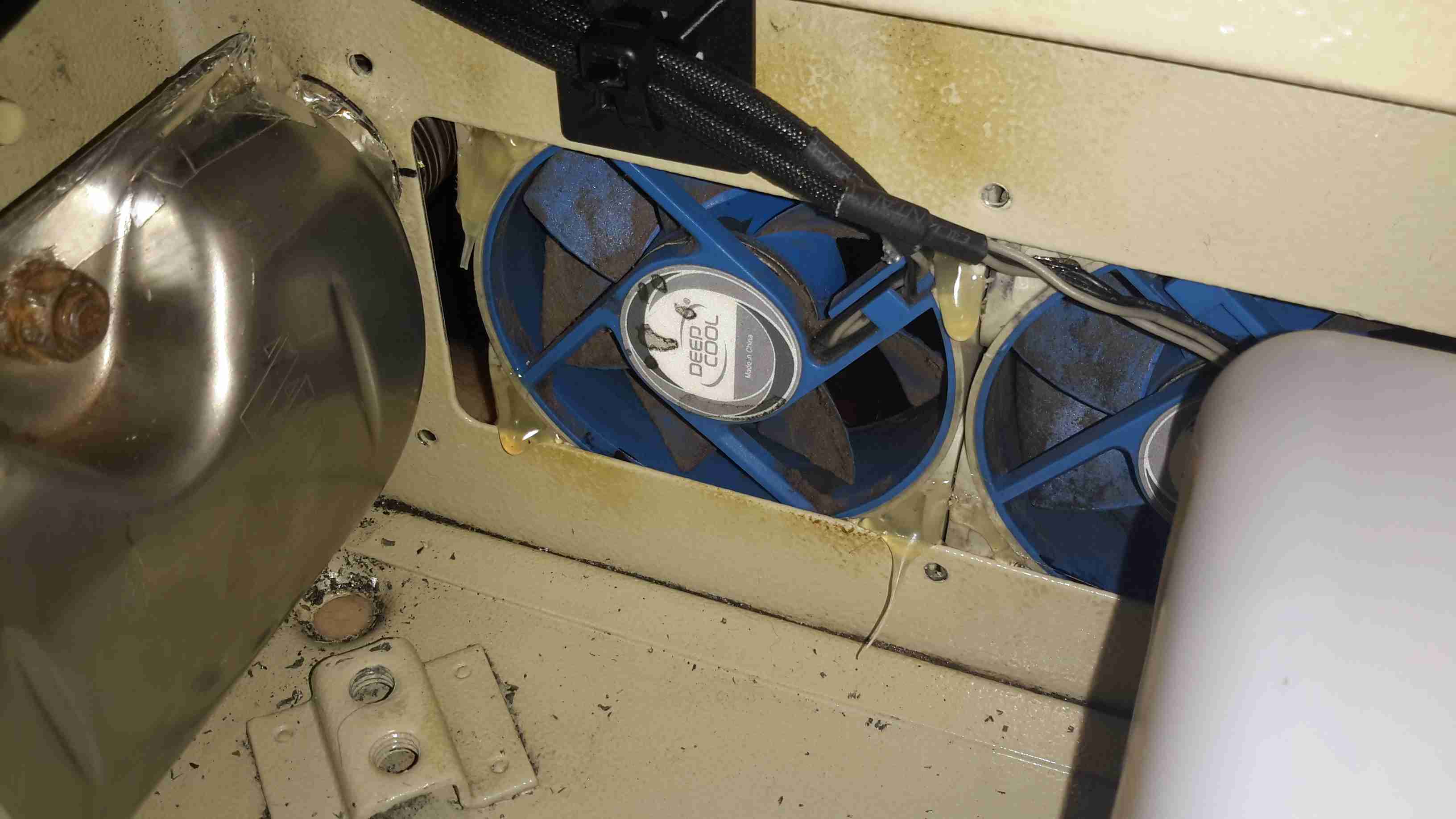
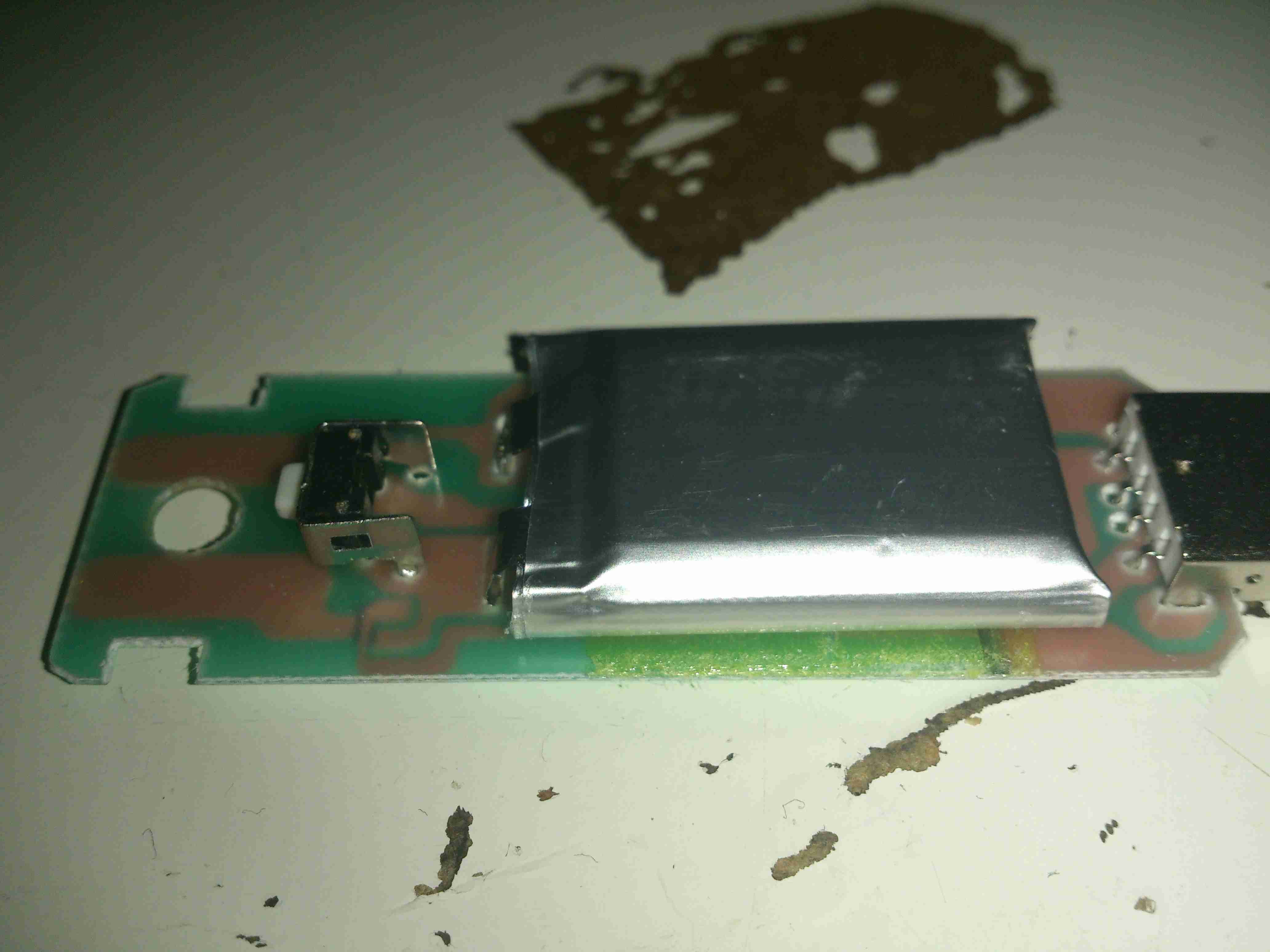
The combustion fan motor is in the ECU compartment, nicely sealed away from the elements. There is no speed sensor on these blowers, unlike the Eberspacher ones.

Motor Details
Motor Details

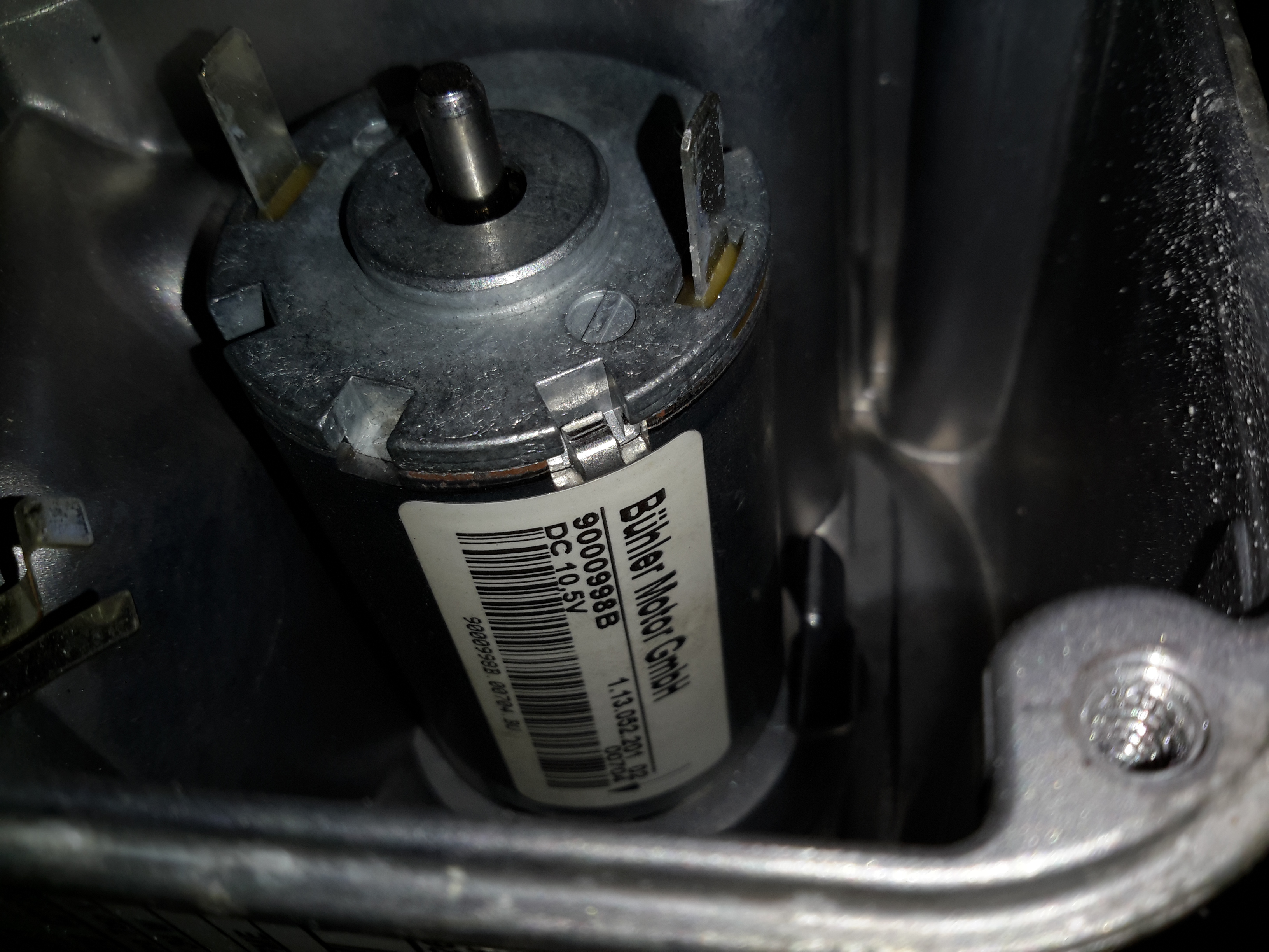
The motor is a Buhler, rated at 10.5v.

Water Ports & Combustion Fan Cover

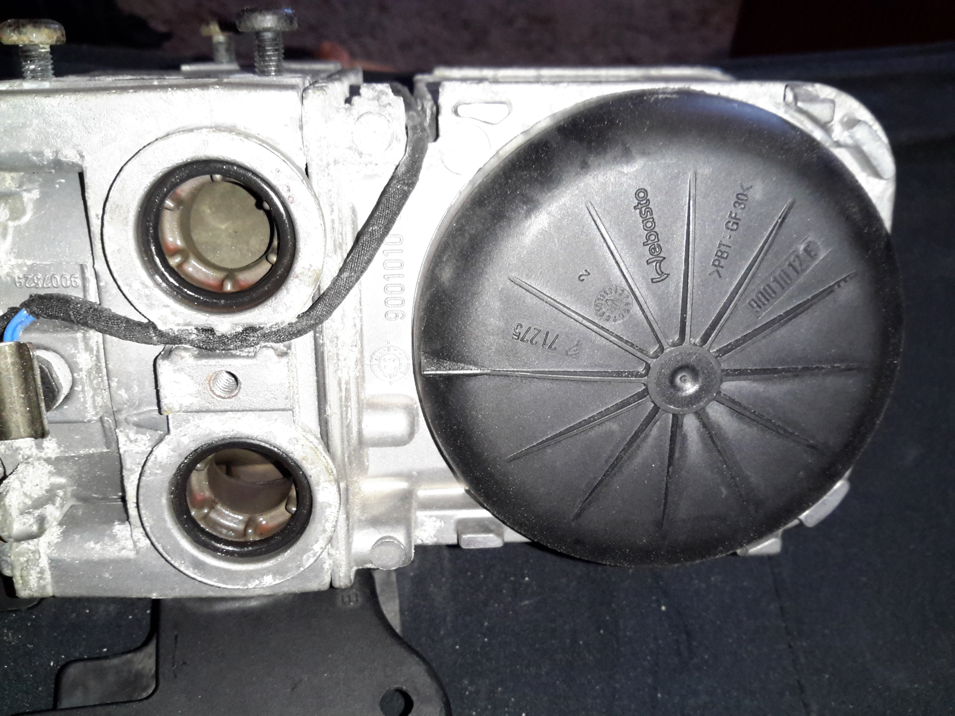
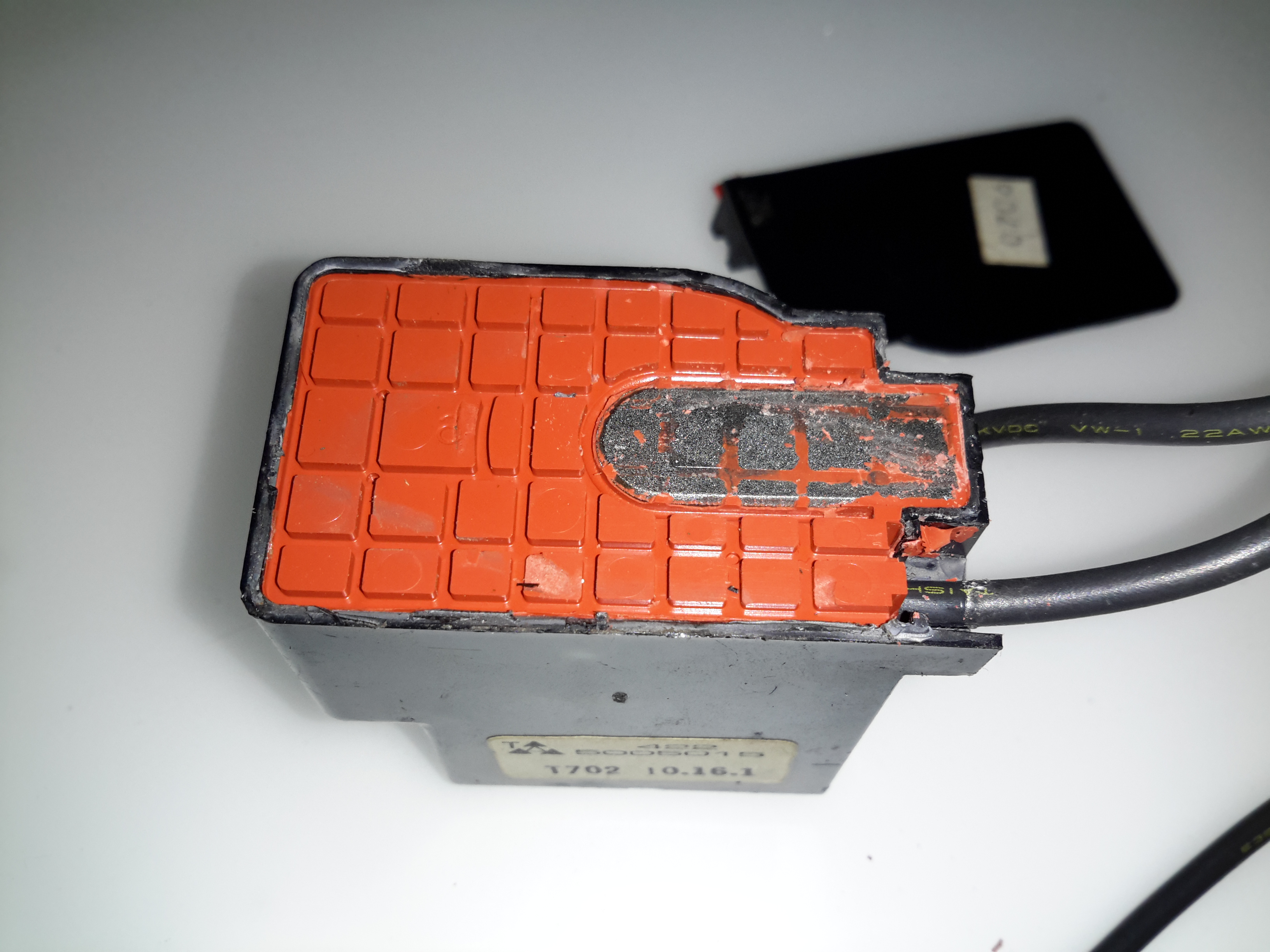
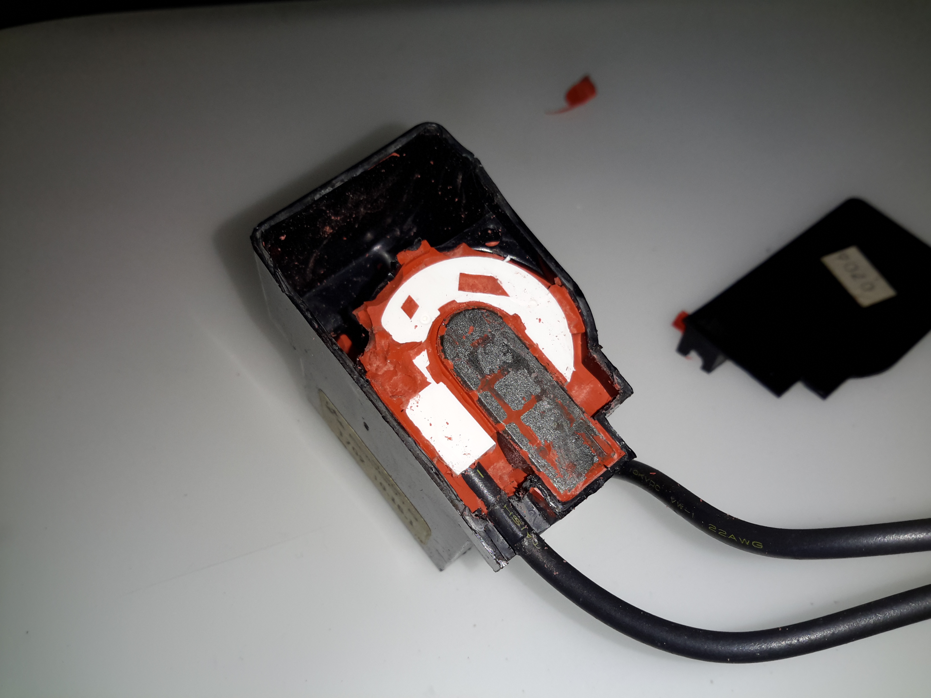
Unclipping the cover from the other end reveals the combustion fan, it’s under the black cover. (These are side-channel blowers, to provide the relatively high static pressure required to run the burner).

Sensor Clip
Sensor Clip

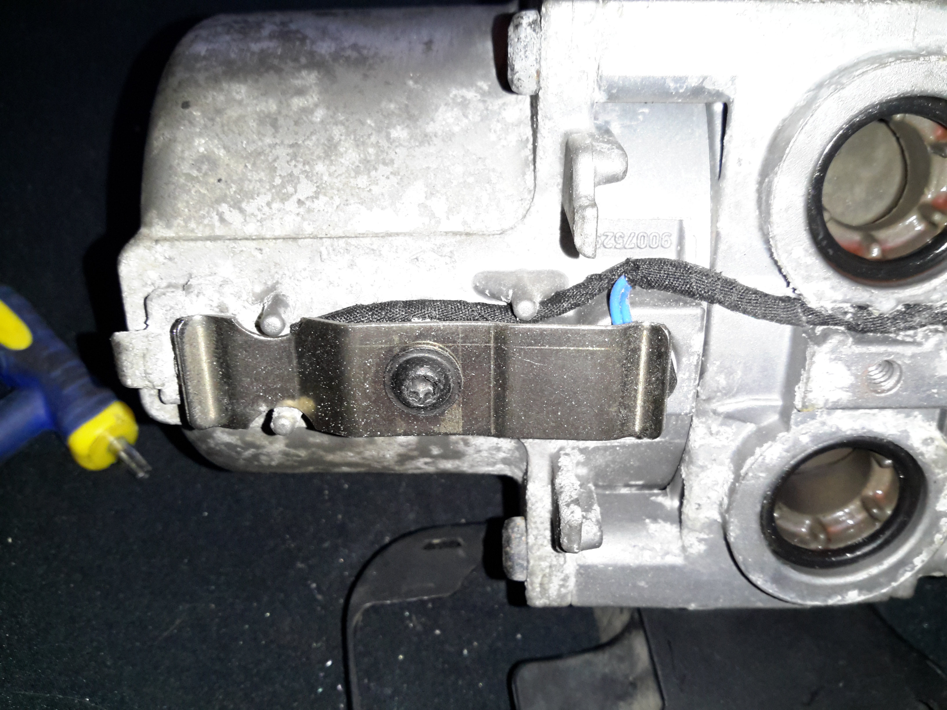
The overheat & temperature sensors are on the end of the heat exchanger, retained by a stainless clip.

Temp & Overheat Sensors

With the clip removed, the sensors can be seen better. There’s some pretty bad corrosion of the aluminium alloy on the end sensor, it’s seized in place.

Burner
Burner

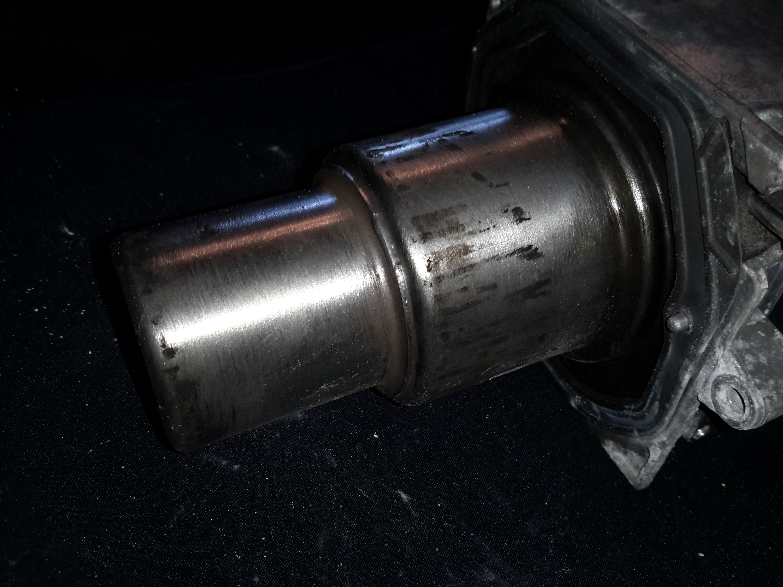
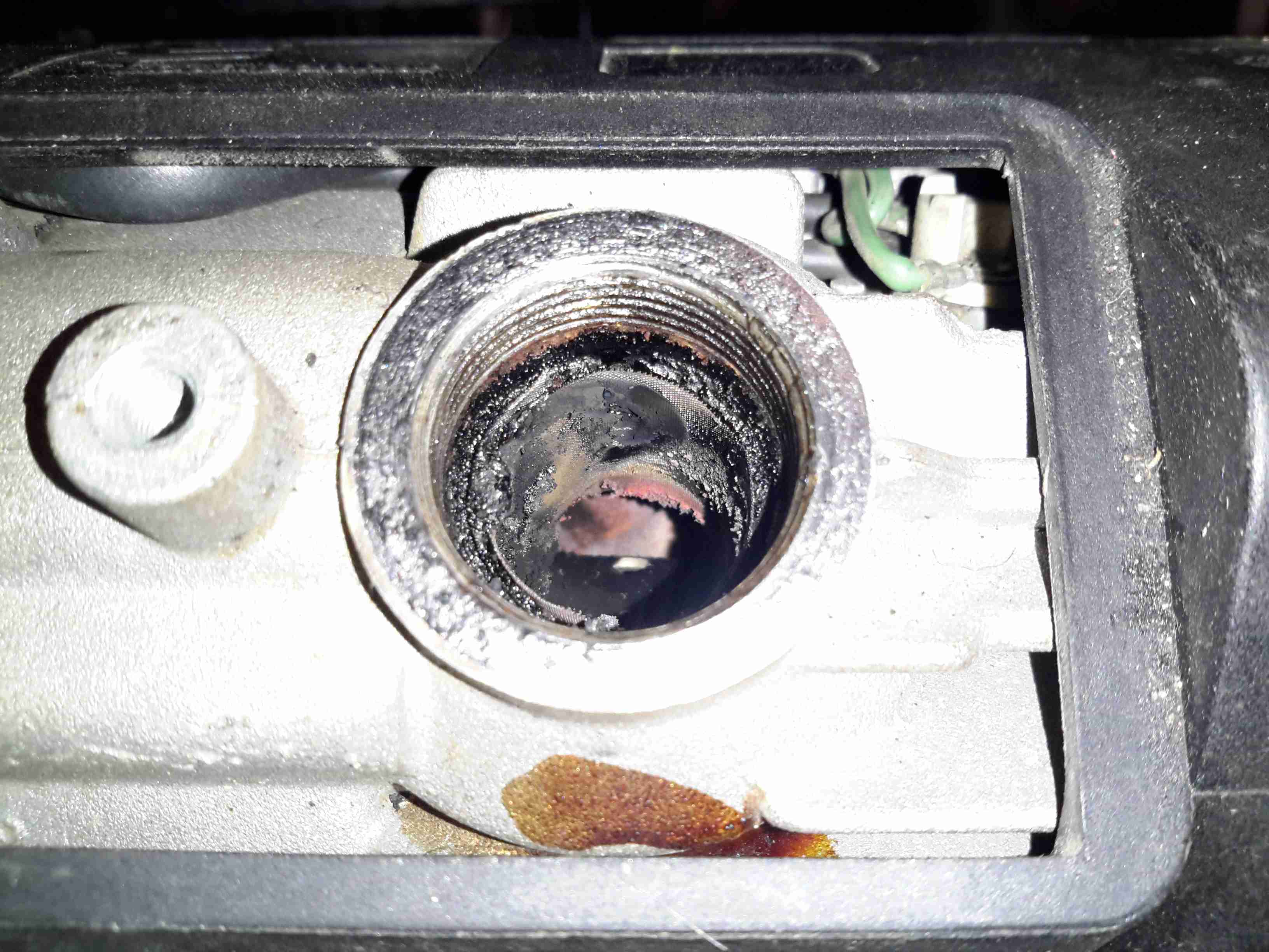
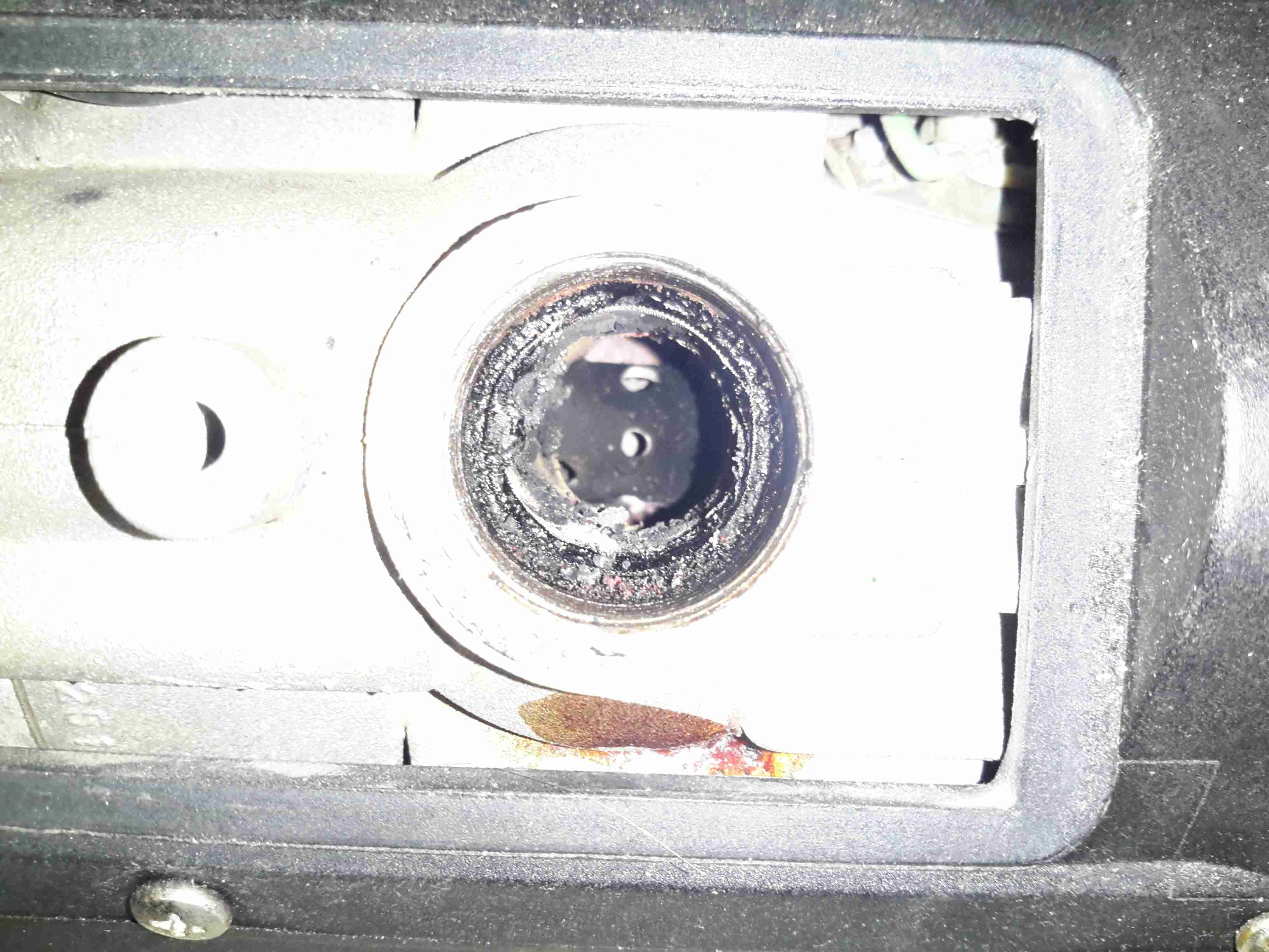
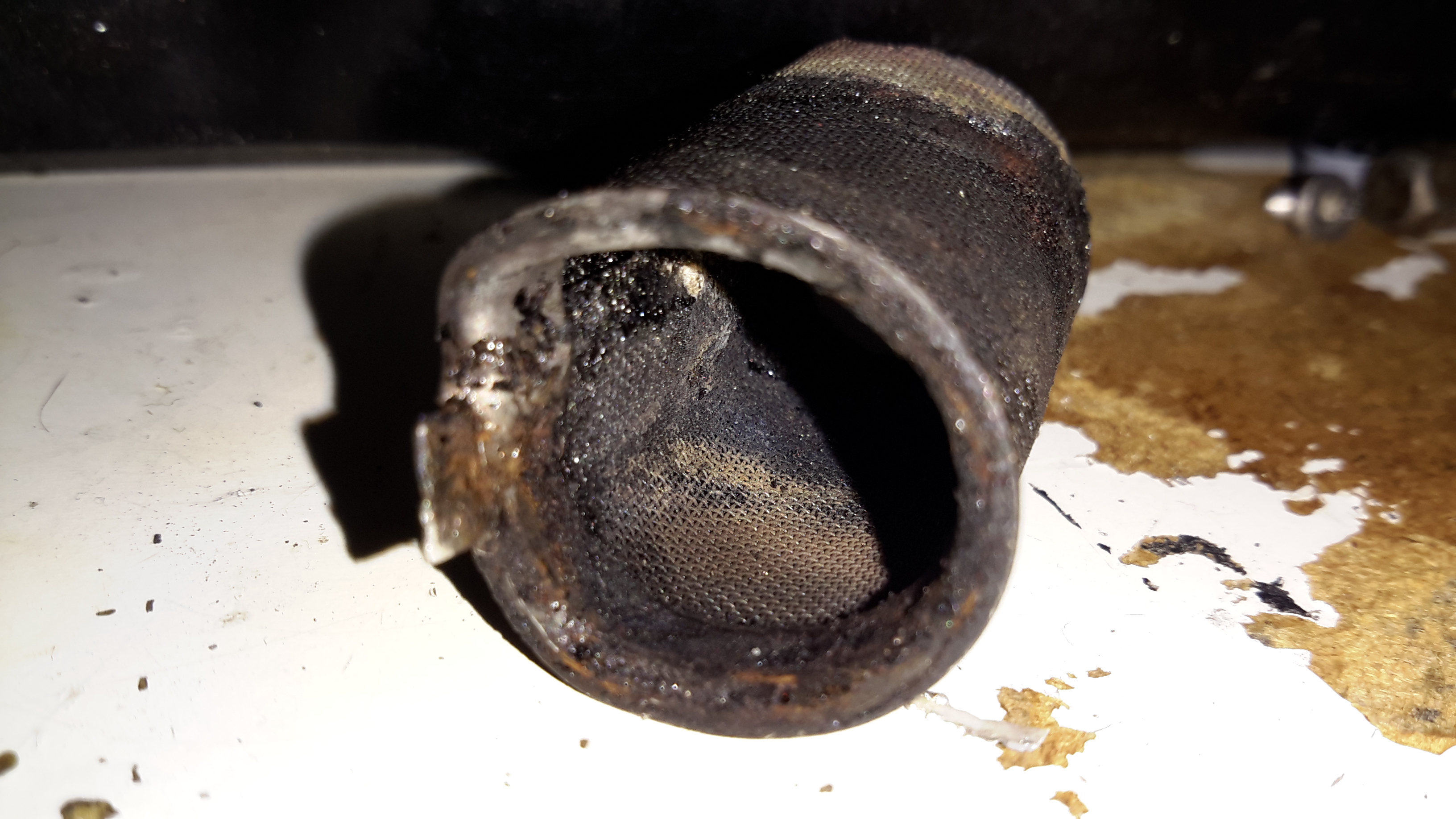
The heater splits in half to reveal the evaporative burner itself. I’ve already cleaned the black crud off with a wire brush here, doesn’t look like this heater has seen much use as it’s pretty clean inside.

Burner Chamber
Burner Chamber

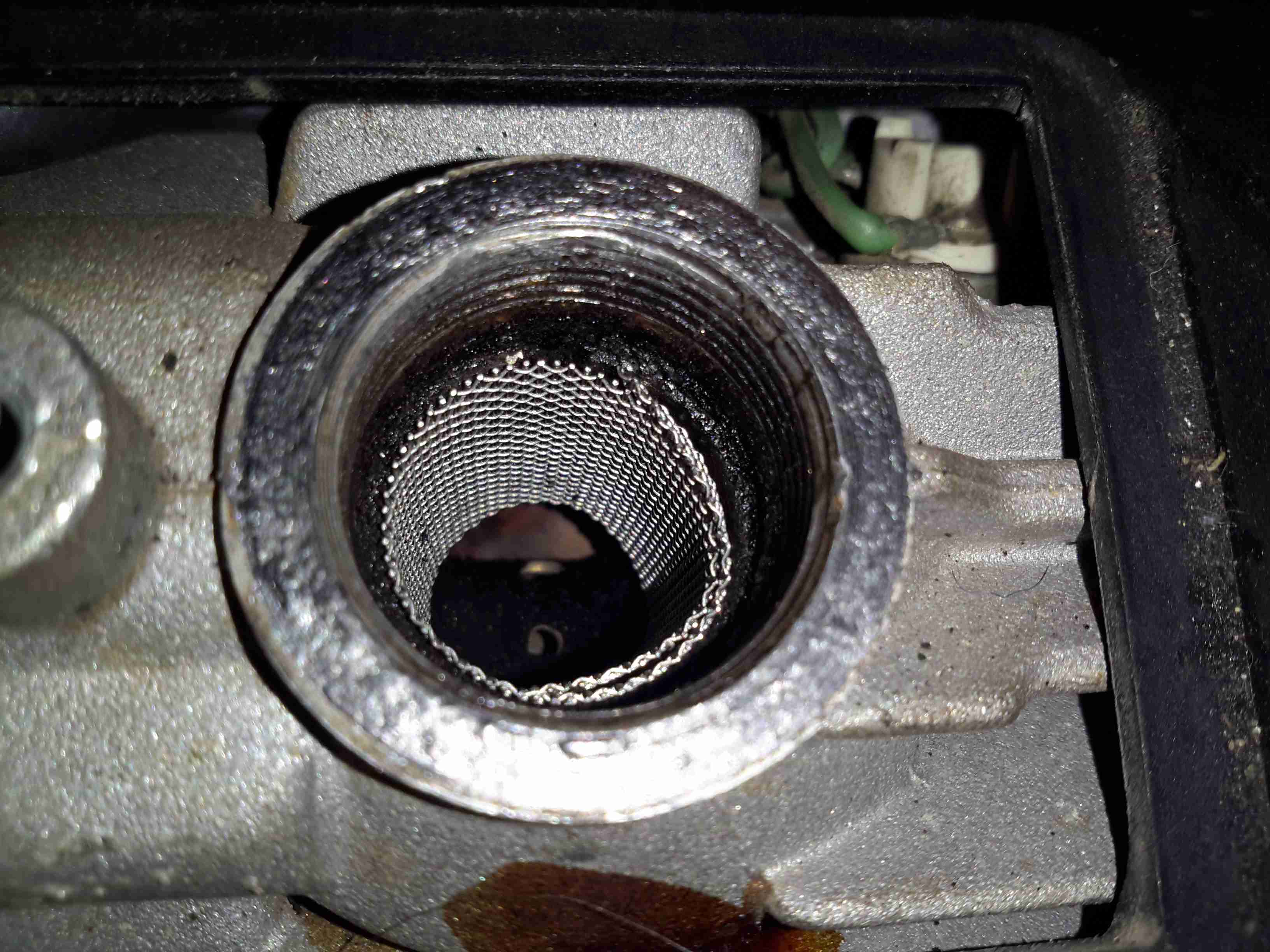
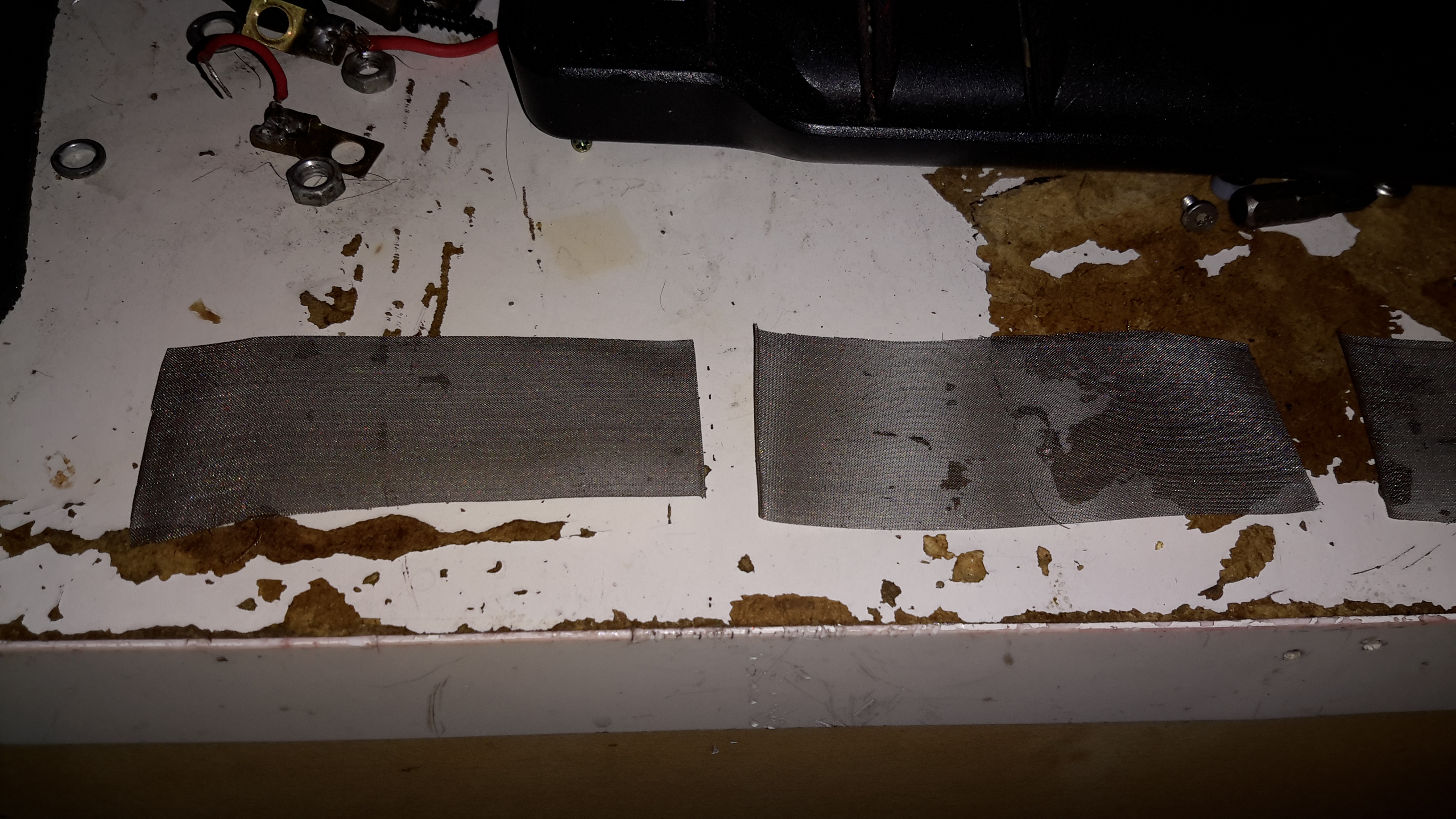
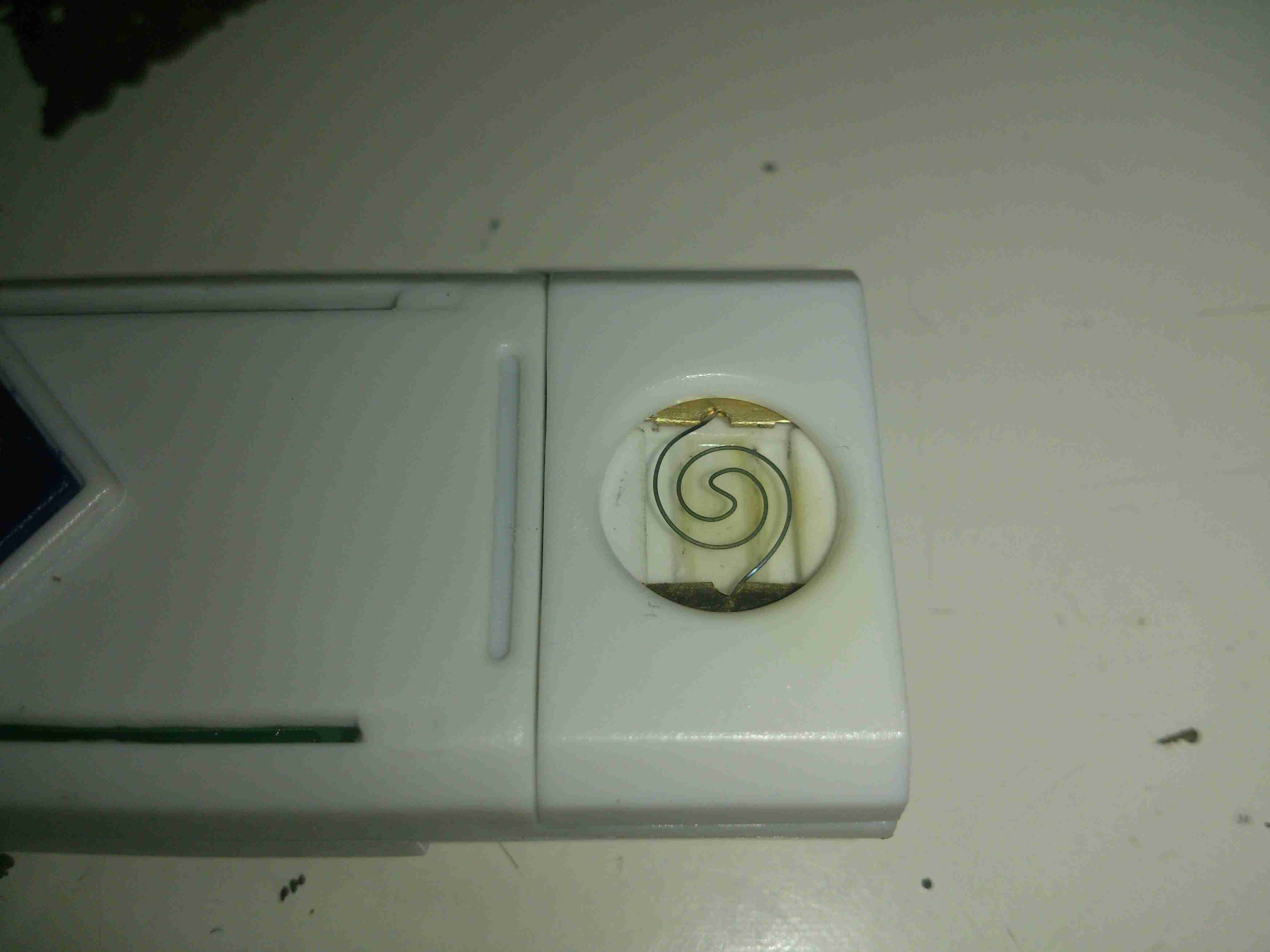
Inside the burner the fuel evaporates & is ignited. There is a brass mesh behind the backplate of the burner to assist with vaporisation.

Glow Plug
Glow Plug

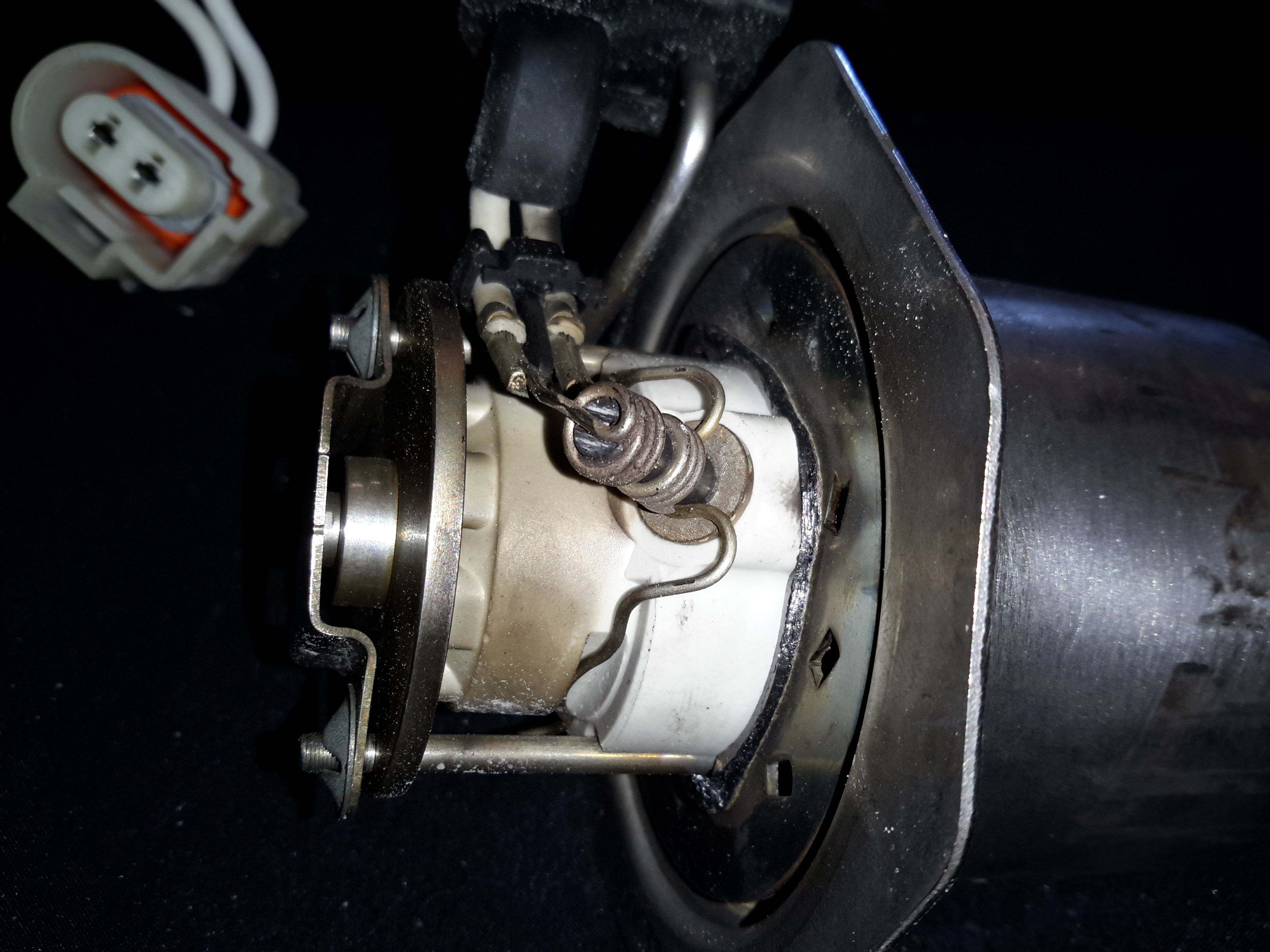
The glow plug is fitted into the side of the burner ceramic here. This is probably a Silicon Carbide device. It also acts as a flame sensor when the heater has fired up. The fuel inlet line is to the left under the clamp.

Heat Exhanger
Heat Exhanger

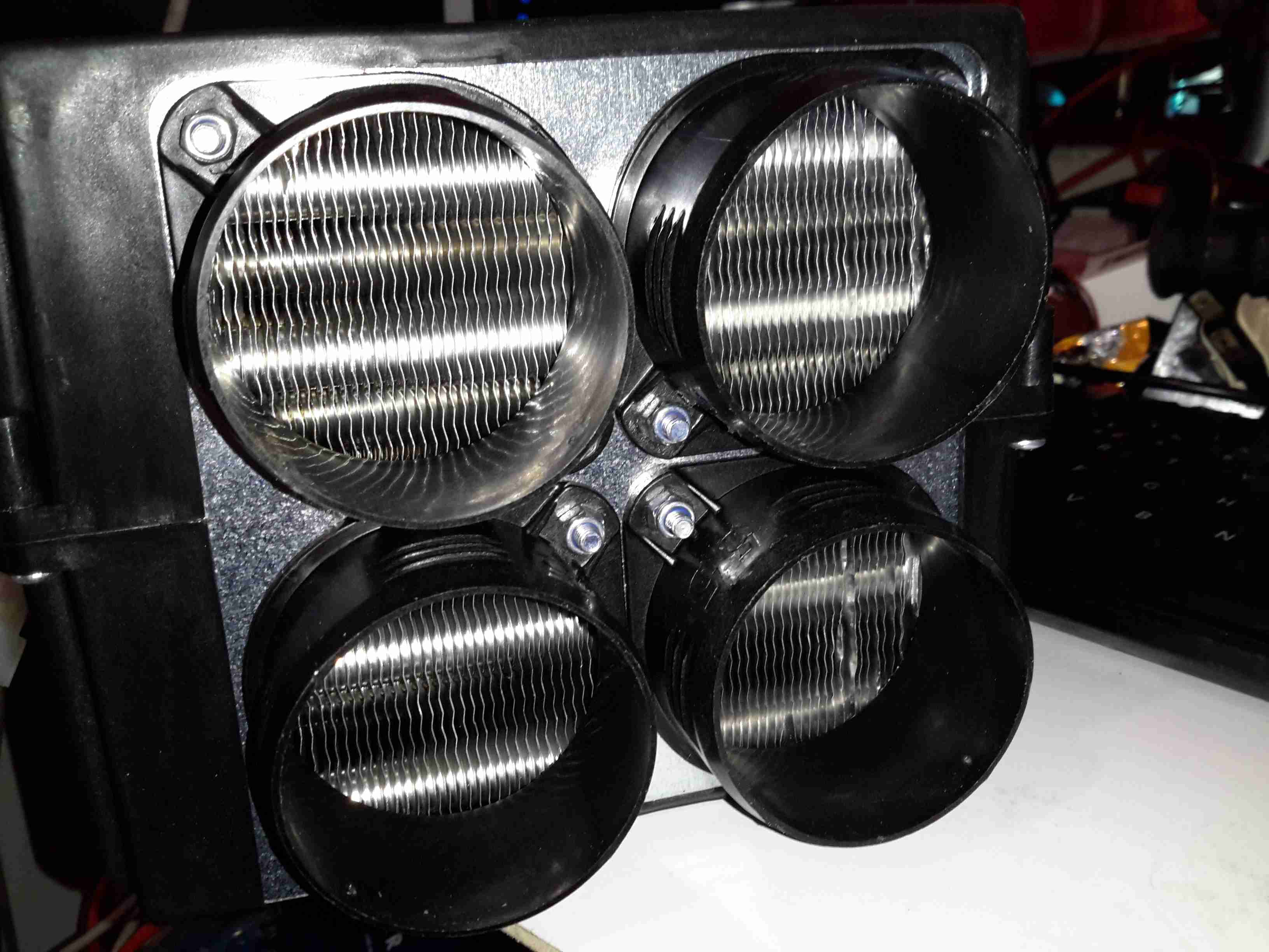
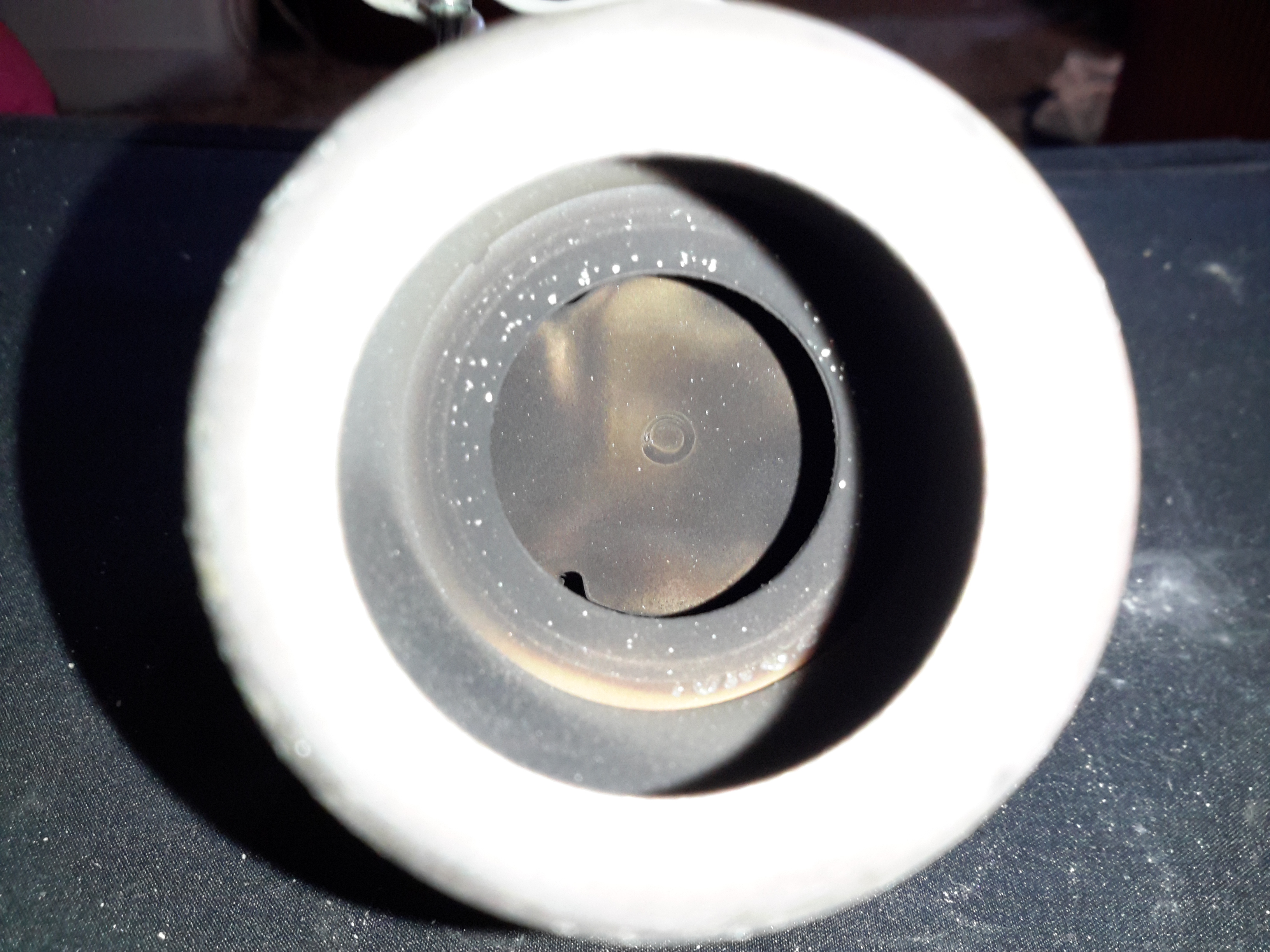
The hot gases from the burner flow into the heat exchanger here, with many fins to increase the surface area. There’s only a couple of mm coating of carbon here, after 10 years on the car I would have expected it to be much more clogged.

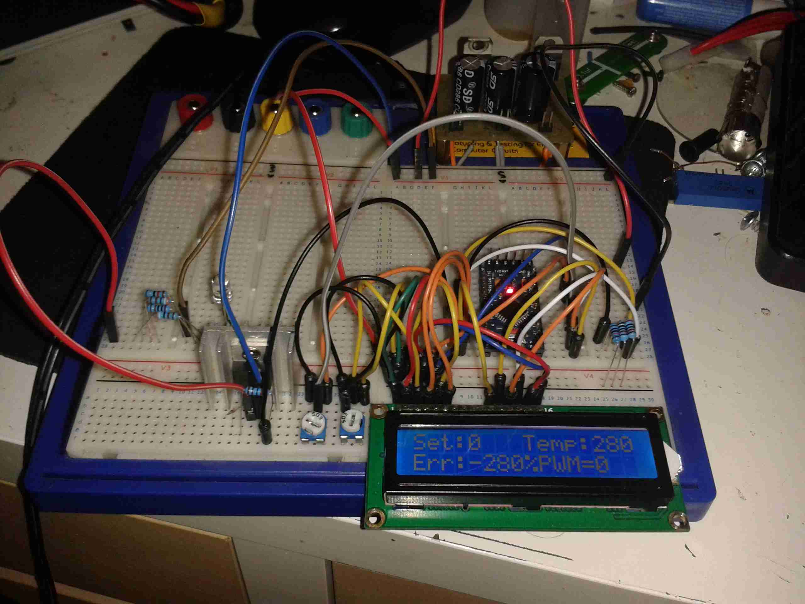
I’m currently waiting on some components to build an interface so I can get the Webasto Thermo Test software to talk to the heater. Once this is done I can see if there are any faults logged that need sorting before I can get this heater running, but from the current state it seems to be pretty good visually. More to come once parts arrive!

The full service manual for these heaters can be grabbed from here, along with the wiring details for the Jaguar implementation & the Thermo Test software for talking to them:

[download id=”5618″]

[download id=”5620″]

[download id=”5622″]

Posted on 4 Comments

DIY Eberspacher Glowplug Screens: The Test Of Time

Some time ago I did a couple of posts on cheapening up the maintenance of Eberspacher hot air heaters by making the glow plug screens myself. Now one of my pieces of stainless mesh has been in the heater for nearly a year, and the heater is starting to get a bit smoky on a cold start. This is usually a sign that the screen isn’t allowing the fuel to vaporise quick enough for the glow plug to ignite the flame, because it’s becoming blocked. So far the heater has had about 150L of diesel through it with my DIY screen.

Old Screen
Old Screen

After removing the plug, here’s what’s left of the screen. The bottom end has completely disintegrated, but this is to be expected – OEM screens do the same thing as this end is exposed to the most heat in the burner. There’s quite a bit of coke buildup on the top end of the screen around the fuel nozzle, again this isn’t surprising, as this is the coolest part of the heater not all the heavier fractions of the diesel fuel have the chance to vaporise.

Innards
Innards

Looking further down into the mixing tube of the main burner, everything looks good. There’s a coating of soot in there, but no tar-like build up that would tell me the unit isn’t burning properly. Another advantage of making my own screens is that they’re much easier to extract from the hole once they’ve been in there for months. The OEM screens have a stainless ring spot welded to the mesh itself to hold it’s shape, and once there’s enough fuel residue built up the entire mess seizes in place, requiring some sharp pokey tools & some colourful language to remove. The single loop of mesh held in place by it’s own spring pressure is much easier to remove as it collapses easily.

New 80 Mesh Screen
New 80 Mesh Screen

I’ve decided to change the mesh size of the screen while I’m in here, in this case to 80 mesh, which is much closer to the OEM screen size. There doesn’t seem to be much of a difference so far in either the starting or running capability of the heater, although the thicker wire of this screen might last longer before disintegrating at the burner end.

Posted on Leave a comment

nb Tanya Louise Heating Upgrades – Saloon Heating

With the installation of the new diesel fired heater we’ve noticed a small problem – since the only heat source in the saloon is the stove, even with the diesel heater fired up the temperature doesn’t really change much, as the heat from the radiators in the both the cabins & the head isn’t spreading far enough.

The solution to this problem is obviously an extra radiator in the saloon, however there isn’t the space to fit even a small domestic-style radiator. eBay turned up some heater matrix units designed for kit cars & the like:

3.8kW Matrix
3.8kW Matrix

These small heater matrix units are nice & compact, so will fit into the back of a storage cupboard next to the saloon. Rated at a max heat output of 3.8kW, just shy of the stove’s rated 4kW output power, this should provide plenty of heating when we’re running the diesel heater rather than the fire.

Water & Power
Water & Power

The blower motor has a resistor network to provide 3 speeds, but this probably won’t be used in this install, water connections are via 15mm copper tails. The current plan is to use a pipe thermostat on the flow from the boiler to switch on the blower when the water temperature reaches about 40°C.

Hot Air Outlets
Hot Air Outlets

The hot air emerges from the matrix via 4 55mm duct sockets. This gives enough outlets to cover both the saloon & the corridor down to the cabins.

Hot Air Vents
Hot Air Vents

Standard 60mm Eberspacher style vents will be used to point the warmth where it’s needed.

More to come soon with the install!

Posted on 2 Comments

nb Tanya Louise Heating Upgrades – The Pumps


Pierburg WUP1
Pierburg WUP1

With some recent upgrades to the boat’s heating system, the hot water circulation pumps we’ve been using are becoming far too small for the job. After the original Johnson Marine circulation pump died of old age (the brushes wore down so far the springs ate the commutator) some time ago, it was replaced with a Pierburg WUP1 circulation pump from a BMW. (As we’re moored next to a BMW garage, these are easily obtainable & much cheaper than the marine pumps).

WUP1 Cutaway
WUP1 Cutaway

These are also brushless, where as the standard Johnson ones are brushed PM motors – the result here is a much longer working life, due to fewer moving parts.

The rated flow & pressure on these pumps is pretty pathetic, at 13L/min at 0.1bar head pressure. As the boat’s heating system is plumbed in 15mm pipe instead of 22mm this low pressure doesn’t translate to a decent flow rate. Turns out it’s pretty difficult to shove lots of water through ~110ft of 15mm pipe ;). Oddly enough, the very low flow rate of the system was never a problem for the “high output” back boiler on the stove – I suspect the “high output” specification is a bit optimistic.
This issue was recently made worse with the addition of a Webasto Thermo Top C 5kW diesel-fired water heater, which does have it’s own circulation pump but the system flow rate was still far too low to allow the heater to operate properly. The result was a rapidly cycling heater as it couldn’t dump the generated hot water into the rest of the system fast enough.

The easiest solution to the problem here is a larger pump with a higher head pressure capability. (The more difficult route would be completely re-piping the system in 22mm to lower the flow resistance). Luckily Pierburg produce a few pumps in the range that would fit the job.

Pierburg CWA-50
Pierburg CWA-50

Here’s the next size up from the original WUP1 pump, the CWA50. These are rated at a much more sensible 25L/min at 0.6bar head pressure. It’s physically a bit larger, but the connector sizes are the same, which makes the install onto the existing hoses easier. (For those that are interested, the hose connectors used on BMW vehicles for the cooling system components are NormaQuick PS3 type. These snap into place with an O-Ring & are retained by a spring clip).
The CWA50 draws considerably more power than the WUP1 (4.5A vs 1.5A), and are controllable with a PWM signal on the connector, but I haven’t used this feature. The PWM pin is simply tied to the positive supply to keep the pump running at maximum speed.

Once this pump was installed the head pressure immediately increased on the gauge from the 1 bar static pressure to 1.5 bar, indicating the pump is running at about it’s highest efficiency point. The higher water flow has so far kept the Webasto happy, there will be more to come with further improvements!

CWA-50 Pump Teardown

CWA50 Cutaway
CWA50 Cutaway

Above is a cutaway drawing of the new pump. These have a drilling through the shaft allows water to pass from the high pressure outlet fitting, through the internals of the pump & returns through the shaft to the inlet. This keeps the bearings cool & lubricated. The control & power drive circuitry for the 3-phase brushless motor is attached to the back & uses the water flowing through the rotor chamber as a heatsink. Overall these are very well made pumps.

Impeller
Impeller

Here’s the impeller of the pump, which is very small considering the amount of power this unit has. The return port for the lubricating water can be seen in the centre of the impeller face.

3-Phase Driver
3-Phase Driver

Inside the back of the pump is the control module. The main microcontroller is hiding under the plastic frame which holds the large power chokes & the main filter electrolytic.

Posted on 2 Comments

CRT Flyback / Line Output Transformer Destructive Teardown

Small Flyback Transformer

Here’s a small flyback / Line Output Transformer from a portable colour TV set. Usually these transformers are vacuum potted in hard epoxy resin & are impossible to disassemble without anything short of explosives. (There are chemical means of digesting cured epoxies, but none of them are pleasant). This one however, was potted in silicone, so with some digging, the structure of the transformer can be revealed.

Cap Removed
Cap Removed

The cap was glued on to the casing, but this popped off easily. The top of the core is visible in the silicone potting material.

The Digging Starts
The Digging Starts

A small screwdriver was used to remove the potting material, while trying not to damage the winding bobbin & core too badly. The bulge in the casing that I originally thought might house a voltage multiplier turns out to be totally empty. The white plastic bobbin is becoming visible around the core.

Bobbin
Bobbin

After some more digging & a lot of mess later, the entire transformer is revealed. The primary & auxiliary secondaries are visible at the bottom of the transformer, next to the pins. These transformers have multiple windings, as they’re used not only for supplying the final anode voltage of several Kilovolts to the CRT, but many of the other associated voltages, for the heater, grids, focus electrodes, etc. These lower voltage windings are on the same part of the core as the primary.
Above those is the main high voltage secondary winding, which looks to be wound with #38-#40AWG wire (about the thinnest available, at 0.07mm diameter. This is wound in many sections of of a few hundred turns each to increase the insulation resistance to the high voltage. The main anode wire emerges from the top of the bobbin.

Output Rectifier
Output Rectifier

Hidden in a recess at the top is the main HV rectifier, which on this small transformer is a single device (it’s probably not internally, most likely a series stack of diodes to get the PIV rating required).

Posted on 2 Comments

Eberspacher D5W ECU Constant Overheat Error

Eberspacher ECU 25 1599 50 00 00

Here’s another Eberspacher control unit, this time from an ancient D5W 5kW water heater. The system in this case is just flaky – sometimes the heater will start without fault & run perfectly, then suddenly will stop working entirely.
The error codes are read on these very old units via an indicator lamp connected to a test terminal. In this case the code was the one for Overheat Shutdown.

Considering this fault occurs when the heater is stone cold, I figured it was either a fault with the sensor itself or the ECU.

Temperature Sensor
Temperature Sensor

The temperature sensor is located on the heat exchanger, right next to the hot water outlet fitting. I’m not sure what the spec is, but it reads exactly 1KΩ at room temperature.

ECU PCB
ECU PCB

The PCB is held into the aluminium can by means of crimps around the edge that lock into the plastic terminal cover. Inserting a screwdriver & expanding the crimps allows the PCB to be slid out.

Casing Crimps
Casing Crimps

The factory date stamp on the microcontroller dates this unit to March 1989 – considerably older than I expected!
Unlike the newer versions that use transistors, this ECU has a bunch of PCB relays to do the high current switching of the water pump motor, fan motor & glowplug.
Overall the board looks to be solidly constructed, with silicone around all the larger components.

ECU PCB Solder Side
ECU PCB Solder Side

Here’s the solder side of the PCB, which has a generous coating of sealant to keep moisture out.

Bad Joint Closeup
Bad Joint Closeup

Looking at the solder joints for the row of relays on the top side of the PCB, it looks like that there’s some dry joints here.
I suspect that years of vibration has taken it’s toll, as the relays are otherwise unsupported. It wouldn’t be possible to use silicone to secure these devices as they are completely open – any sealant would likely stop them from operating.

Resoldered Joints
Resoldered Joints

Using a very hot soldering iron I managed to get the joints to reflow properly, using lots of flux to make sure the conformal coating didn’t interfere with the reflow.

Posted on 4 Comments

TS100 12-24v Soldering Iron

Handle
Handle

When I ordered the tiny USB soldering iron, I decided a proper iron upgrade would be a good idea. Looking around for something that didn’t require AC mains power turned up the TS100, a Chinese design, that unusually is actually very good! Above is the handle itself, with it’s small OLED display & two operation buttons.
This iron is controlled by a STM32 ARM microcontroller, the firmware & schematics are completely open-source.

DC Input Jack / USB Port

The bottom end of the iron has the main DC input jack, designed with laptop chargers in mind (DC input range from 10v-24v). Above that is the micro USB port for programming.

Heating Element Socket

The iron tips slot into the other end, many different tip types & shapes are available. The one supplied was the simple conical tip.

Standby Screen
Standby Screen

Plugging the iron into some power gets a standby screen – it doesn’t just start heating immediately, for safety.

Heating
Heating

The left hand button starts the heater, which on a 24v input voltage gets to operating temperature well within 10 seconds.

Temperature Stable
Temperature Stable

The right hand screen icon changes when the temperature has stabilized. The control PCB has an integrated accelerometer, leaving the iron hot for a few minutes triggers a timeout & it powers down. Once picked up again, the heater instantly restarts.
The operating temperature is adjustable with the pair of buttons, from 100°C to 400°C.

Different Bits
Different Bits

Here’s a selection of bits for the iron. The design is very similar to the Hakko T15 series of irons, but these are a much shorter version. Like the Hakko versions, the actual tips aren’t replaceable, once the bit burns out, the entire assembly is replaced.

TS100 Soldering Iron

Here’s the iron fully assembled. The entire device is about the same length as just the heating element from a Hakko T15!

Posted on Leave a comment

DIY Eberspacher Glowplug Screens: Recap

A while ago I posted about the glowplug screens in Eberspacher heaters, and making some DIY ones, as the OEM parts are hideously expensive for a piece of stainless mesh (£13).

Old Screen
Old Screen

Above is the old factory screen that I extracted after only 5 gallons of diesel was run through it, it’s heavily clogged up with carbon & tar. The result of this clogging is a rather slow & smoky start of the heater & surging of the burner while at full power.
It wasn’t as badly stuck in the chamber as some I’ve removed, but extracting it still caused the steel ring to deform, this was after using a scalpel blade to scrape the carbon off the rim.

At the time I did some tests with some spare copper mesh I had to hand, but the problem with copper is that it’s very soft & malleable, so didn’t really hold it’s shape well enough. The factory screens are spot welded to keep them in shape, but as I don’t have a spot welder, I am relying on the mesh having a bit of springiness to keep it in place against the walls of the glowplug chamber.

eBay provided a piece of 120 mesh stainless steel mesh, 300mmx300mm for £8. It’s a bit finer than the stock stuff, but appears to work perfectly fine as long as there’s no gunk in the fuel to clog it up.

I cut a strip off the large piece, as wide as the OEM screen, about 32mm. This 300mm long strip is then cut into 4 pieces, each 75mm long. (it’s easily cut with scissors, but mind the stray wires on the edges! They’re very sharp & penetrate skin easily!).

Mesh Screen
Mesh Screen

These pieces are just the right size to form a complete loop in the glowplug chamber, and the stainless is springy enough so that it doesn’t deform & become loose.
The OEM screen is multiple turns of a more coarse mesh, but the finer mesh size of the screens I’m using means only one turn is required. Multiple turns would probably be too restrictive to fuel flow.
With one of these pieces of mesh in place, the heater starts instantly, without even a wisp of smoke from the exhaust. Burner surging is also eliminated. Even if the service life of my DIY replacement isn’t as long as an OEM screen, the low price for such a large number of replacements certainly offsets that disadvantage!

A piece of mesh from eBay would provide enough material for quite a lot of replacements, and probably more than the service life of the burner itself!

Posted on Leave a comment

Mini Teardown: Eberspacher 701 BT Controller

It’s well known that there are two versions of the 701 type controller available for Eberspacher heaters, the version with the blue logo is the official un-restricted model, while the version with the white logo is a version built for BT that restricts the heater to 1 hour runtime & has no diagnostics built in.
As these devices are microcontroller driven, I assumed that the hardware would be the same, only the code running in the micro being the bit that Eberspacher changed. This option would certainly have been the lowest cost.

Controller PCB Rear
Controller PCB Rear

Here’s the PCB removed from the plastic housing. There are definitely some differences that I can tell. As the un-restricted version has an extra wire for the diagnostic serial interface, and this board has no unpopulated parts, the PCB is definitely a different version.
In the centre is a Microchip PIC16C622 microcontroller, the OTP version in this case for cost reductions. (I may try reading the binary from this chip in the future, chances are it’s code protected though).
Below the micro is an NXP PCF8577C 32-segment LCD controller, this has an I²C interface to the PIC.
The temperature control function on these heaters is done via applying a resistance to one of the control lines, between 1750Ω-2180Ω, ±80Ω. (Very odd values these, not to mention no standard components can create this range easily, bloody engineers >_<). This is accomplished in hardware with a BU2092F I²C shift register from Rohm, which is connected to a bank of resistors. The microcontroller will switch combinations of these into the circuit to get the range of resistances required.
The rest of the circuit is local power regulation & filtering.

Controller PCB Front

There’s not much on the other side of the PCB, just the LCD itself & the contacts for the buttons.

Posted on 4 Comments

Eberspacher Controller & Remote

7-Day Programmer
7-Day Programmer

The Eberspacher heaters can be controlled with a single switch, but it’s more convenient to have some temperature control & the option of a timer. Above is an ex-BT 701 series controller, with built in 7-day programmer. Being an ex-BT van version though, it’ll only switch the heater on for 1 hour at a time.
To get around this slight niggle, I fitted a bypass toggle switch.

Remote Control
Remote Control

For a bit of extra convenience, I got an RF remote controlled relay module from eBay (£5).
This allows me to switch things on remotely, so I can return to a nice toasty tent while camping.
There is an official RF remote for Eberspacher heaters, but I’ve no doubt they’re hideously expensive.

RF Receiver
RF Receiver

Here’s the receiver PCB, there’s an EEPROM & a microcontroller onboard for handling the codes the remotes send, but as the number has been scrubbed off the micro, no data there. This uses a standard RF receiver module.

RF Remote
RF Remote

Here’s the remote itself, this uses a 12v battery instead of a 3v lithium cell. A little of a pain since these batteries can be a bit pricey.
As this RF system operates on 315MHz, it’s technically illegal in the UK, but I was unable to find a 433MHz version with the features required. Nevermind ;).

Controller Internals

Here’s the module installed in the controller casing. I have since run the antenna wire around the edge of the case to try & get the furthest range on receive. The relay contacts are just paralleled across the bypass switch, so when the relay energizes the heater fires up.
Luckily the thermostatic control portion of the 701 programmer is operational even when heating mode is not active.

Posted on 6 Comments

Eberspacher Tent Heating System

The "Tenterspacher"
The “Tenterspacher”

I go camping on a regular basis here in the UK, and often even in summer it’s horribly cold at night in a field somewhere in the middle of Leicestershire. This doesn’t go too well with my severe aversion to being cold.
For the past several years I’ve used a Tilley lamp for some heat & light while at festivals & general camping, but it’s heat output is less than stellar when used in a 6-man tent.

An Eberspacher diesel heater was what was required for the job. Above is the unit as it’s built at the moment – I’ve used an old D1LCC 1.8kW heater that was recently decommissioned from nb Tanya Louise, as it’s getting a bit funny about what kind of fuel it’ll run on in it’s old age. It’ll work perfectly well on kerosene though – a fuel I already take with me camping for the Tilley.

It’s mounted on a base box, which is a repurposed steel electrical junction box that saw a previous life containing a 3-phase fan motor controller.

Data Plate
Data Plate

Here’s the info on the heater unit itself. Drawing 22W of power at 12v I’ll be getting 1.8kW of heat output – sounds good to me.


Box Internals
Box Internals

Here’s a view into the base box before the circulation fans were fitted, in early prototype stage. I used a small toroid as a clunk on the end of the rubber fuel line 😉

Support Components
Support Components

After a few bits from the Great eBay arrived, here’s the internals of the base unit at present. The fuel tank is a repurposed 2L fridge water container – made of tough HDPE so it’s fuel resistant.
The fuel pump is mounted on the left side next to the tank – having been wrapped in some foam to deaden the continual ticking noise it creates. The exhaust & it’s silencer are mounted at the rear, the silencer being retained by a surplus rubber shock mount. Luckily the exhaust systems on these heaters don’t get particularly hot, so the rubber doesn’t melt.
The exhaust outlet is routed through the frame, to be attached to an external hose. I don’t want combustion gases in the tent with me!

Standard Eberspacher silencers also aren’t gas-tight from the factory – they’re designed to be used in the open on the underframe of a vehicle, so I’ve covered all the seams in aluminium tape to make the system airtight.

Ventilation
Ventilation

To make sure that the support components don’t get overheated with the exhaust being in such close proximity, and to pull a little more heat out of the system, a pair of slow-running 80mm fans has been fitted to the end of the box. These blow enough air through to give a nice warm breeze from the vents on the other end of the base.

Fuel Tank
Fuel Tank

The tank I’ve used just so happened to be the perfect size to fit into the base box, and to tap the fuel off a bulkhead fitting was put into the top of the tank, with a dip tube on the other side. The fuel line itself is tiny – only 4mm.
If the specifications from Eberspacher are to be believed, 2L of fuel on board will allow the system to run for about 8 hours on full power, or 16 hours on minimum power.

Being inside the base, refuelling is a little awkward at the moment, the heater has to completely cool before the exhaust can be detached without receiving a burn, so I’ll be building in a fuel transfer system from an external jerry can later to automate the process – this will also help to avoid messy fuel spills.

More to come when the rest of the system is worked out!

73s for now!

Posted on Leave a comment

Electronic Lighter – eBay Freebie

With a recent order from a Chinese seller on eBay, this little gadget was included in the package as a freebie:

Electronic Lighter
Electronic Lighter

I’ve not smoked for a long time, so I’m not too sure what use I’m going to find for this device, but it’s an electronic lighter!

Pyromaniac Mode
Pyromaniac Mode

Pushing the slider forward reveals a red-hot heater, mounted in the plastic (!) frame.

Charging Mode
Charging Mode

Pushing the other way reveals a USB port to charge the internal battery.

Core Removed
Core Removed

A couple of screws releases the end cap from the cover & the entire core unit slides out. Like all Chinese toys it’s made of the cheapest plastic imaginable, not such a good thing when heat is involved.

Heating Element
Heating Element

The element itself is a simple coil of Nichrome wire, crimped to a pair of brass terminals. The base the heater & it’s terminals are mounted to is actually ceramic – the surround though that this ceramic pill clips into is just the same cheap plastic. Luckily, the element only remains on for a few seconds on each button push, there’s no way to keep it on & start an in-pocket fire, as far as I can see.

Main PCB
Main PCB

The main PCB clips out of the back of the core frame, the large pair of tinned pads on the left connect to the heater, the control IC has no numbering of any kind, but considering the behaviour of the device it’s most likely a standard eCig control IC.

LiPo Cell
LiPo Cell

The other side of the board has the USB port on the right, the Lithium Polymer cell in the centre, and the power button on the left. The cell itself also has no marking, but I’m guessing a couple hundred mAh from the physical size.


Posted on 1 Comment

12v Temperature Controlled Soldering Iron

In my shack, 99% of my gear is all 12v powered, which is good for a few reasons:

  • Single Power Supply – This increases efficiency, as I’m only getting the losses of a single supply.
  • Safety – Mains voltages are dangerous, I’m not fond of working on such equipment.
  • Portability – I can power everything pretty much no matter were I am from a convenient car battery.
  • Convenience – Since everything is single supply, with all the same plugs, I don’t have to think about what goes where. This is more important due to my forgetfulness ;).

The one piece of equipment I regularly use that isn’t 12v is my soldering station. This is a Maplin A55KJ digital unit, which uses a 24v heating element.
While the soldering wand works OK when hooked direct to a 12v power supply (only at half power though), this removes the convenience of having temperature control.

The circuitry inside the unit is PIC microcontroller based, and doesn’t even bother rectifying the AC from the supply transformer before it’s sent to the heater. Because of this there are several reasons why I can’t just hook a DC-DC converter up to it to give it 24v.

It’s sensing the zero-crossing for the triac switch, to reduce heat dissipation, so it refuses to work at all with DC.

On looking at the Great Google, I found a project on Dangerous Prototypes, an Arduino based PID controller for soldering irons.

This requires that the soldering wand itself contains a thermocouple sensor – as the Maplin one I have is a cheap copy of the Atten 938D, it doesn’t actually use a thermocouple for temperature sensing. It appears to read the resistance of the element itself – Nichrome heating elements change resistance significantly depending on temperature.

I’ve managed to find a source of cheap irons on eBay, with built in thermocouples, so I’ve got a couple on order to do some testing with. While I wait for those to arrive, I’ve prototyped up the circuit on breadboard for testing:

Prototype
Prototype

I’ve remapped some of the Arduino pins, to make PCB layout less of a headache, but the system is working OK so far, with manual input for the sensed temperature.
I’m using an IRL520N logic-level HEXFET for the power switching, rated at 10A. As the irons only draw a max of 4.5A, this is plenty beefy enough.
To come up with the +24v supply for the heater, a small DC-DC converter will be used.

More to come when the components for the thermocouple amplifier arrive, and the soldering irons themselves!

Posted on 1 Comment

FE-5680A Rubidium Frequency Standard – Initial Teardown

Physics Package
Physics Package

Here is a quick look inside the FE-5060A Rubidium Frequency Standard. Above you can see the entire physics package, with the rubidium lamp housing on the right hand side. The ribbon cable running into the resonator cavity has the power & signal traces for the internal heater, temperature sensor & Helmholtz coil.

Lamp End
Lamp End

Here is the lamp end of the physics package, with the voltage regulator & RF driver for the lamp. The FETs soldered to the back of the housing are being used as heaters to maintain a constant temperature on the lamp in operation.
The temperature sensor can be seen between the two FETs, with a single copper wire running around the housing to connect to it.

Main frequency synth board. This contains the RS-232 interface & the AD9830A from Analog Devices. This IC is a direct digital synthesizer & waveform generator.


Synthesizer Board
Synthesizer Board
Posted on Leave a comment

DIY Valve Amplifier – Part 1 – Amplifier Section

Components
Components

Here are a few details of a valve amplifier I am building, using the valve related parts from a 1960’s reel to reel tape recorder.

This amplifier is based on an a Mullard ECL82 triode/pentode valve, with an EM84 magic eye tube for level indication.

Beginnings Of The Amplifier

Here the first components are being soldered to the tags on the valve holder, there are so few components that a PCB is not required, everything can be rats-nested onto the valve holders.

Progress
Progress

Progressing with the amplifier section componentry, all resistors are either 1/2W or 2W.

Valve Sockets Fitted

Here the valve holders have been fitted, along with the output transformer, DC smoothing capacitor & the filament wiring, into the top of the plastic housing. At this point all the components that complete the amplifier section are soldered to the bottom of the right hand valve holder.

Wiring
Wiring

Starting the wiring between the valves & the power supply components. The volume control pot is fitted between the valve holders.

Valves Test Fit
Valves Test Fit

The valves here are test fitted into their sockets, the aluminium can at the back is a triple 32uF 250v electrolytic capacitor for smoothing the B+ rail.

Amplifier Section First Test

First test of the amplifier, with the speaker from the 1960’s tape recorder from which the valves came from. the 200v DC B+ supply & the 6.3v AC filament supply is derived from the mains transformer in the background.

Magic Eye Tube Added

Here the magic eye tube has been fitted & is getting it’s initial tuning to the amplifier section. This requires selecting combinations of anode & grid resistors to set the gap between the bars while at no signal & picking a coupling RC network to give the desired response curve.

Final Test
Final Test

Here both valves are fitted & the unit is sitting on it’s case for final audio testing. the cathodes of the ECL82 can be clearly seen glowing dull red here.


In the final section, I will build a SMPS power supply into the unit to allow it to be powered from a single 12v DC power supply.

Posted on Leave a comment

Hot Laminator

Top
Top

Here is a cheap no brand hot laminator. This pulls the paper, inside a plastic pouch through a pair of heated rollers to seal it.

Heater
Heater

Top removed, heater assembly visible. PCB attached to the top cover holds LEDs to indicate power & ready status.

Switch
Switch
Thermostat
Thermostat

Here is the thermostat & thermal fuse, the thermostat switching the indicator on the front panel to tell the user when the unit is up to temperature. This has a self regulating thermostat. Thermal fuse inside the heat resistant tubing is to protect against any failure of the heater.

Motor
Motor

5 RPM motor that turns the rollers through a simple gear system.