Here we have another piece of tech from Sterling Power – this is their Advanced Alternator Regulator, the Pro Reg D. Since I’m rejigging the alternator setup onboard, I figured I’d do a little teardown.
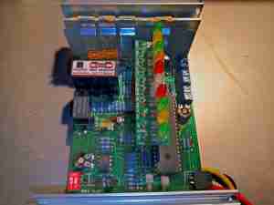
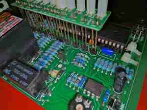
Removing the top cover reveals the main PCB, which is slotted into the Aluminium heatsink extrusion. It’s a pretty well packed board, with both sides packed with tracks. There’s a small fan at the top of the unit, to keep the heatsink cool, but this has never worked for as long as this regulator has been in service.
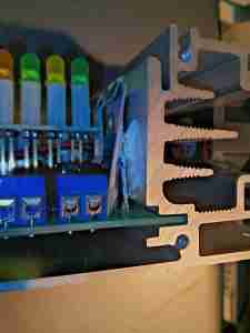
Here would be the reason the fan has never operated – the thermistor which is supposed to monitor the temperature of the heatsink the MOSFETs are clamped to isn’t even in contact with it. Simply glopped with heatsink compound & stuck behind the SIL pad. This is a little sloppy to say the least, and should be in close thermal contact with the heatsink. I’ll have to adjust this mounting.
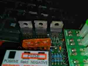
Removing the heatsink shows the main field control FETs, both a P-Channel IRF4905 74A for positive field control, and a N-Channel IRF1010E 84A for negative field control. These are selected by moving the blade fuse between 3 spade terminals. Incedentally, Automotive-type blade fuses are not quick enough to protect semiconductors in the event of a serious fault, the likely result being an intact fuse & totally blown MOSFET. Nevermind.
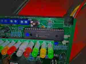
The unit is controlled by a Microchip PIC16F874, in a large package. There’s a couple of trimmers onboard for tweaking the calibration of the regulator, along with a dual DIP switch & a 12/24v link. Display is taken care of by a large row of indicator LEDs on a mezzanine board, there’s also a 4-pin Molex connector for a remote status display.
The LED board is mounted to the main PCB with long pin headers, with no other support. Given the naturally vibrational nature of boats & their engines, having solder joints flapping about in the breeze isn’t a great plan, and fatigue is likely to set in here before long.
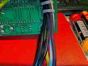
Speaking of vibration, since the cable loom emerging from the aluminium case of the regulator is totally unprotected, the sharp edge of the extrusion has already begun chewing through the insulation! This has occurred after about 50 hours running time since the unit was installed. I’ll add a sleeve over the loom where it pops out of the corner to protect things better. Having the earthed aluminium casing munch it’s way through the insulation & short the entire loom out would not be a great result.
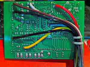
While I’ve got the board out of the casing, I’ve applied a heavy coat of PCB conformal coating to the back to help keep the moisture out, once everything is back together the top of the PCB will get the same treatment after masking off the parts that wouldn’t take kindly to a blasting with conformal coating.

Hi,
while desperately searching the web for some infromation about how to adjust my Pro-Reg D I came to your site.
Great to see that somebody has analyzed the device.
My problem:
The remote control of my PDAR shows e.g. 13.5volt, whereas a high-quality voltmeter shows 19.9volt.
This means that, when charging, the PDAR wants to get 14.4V, but the actual voltage of almost 15V will brun my batteries.
Did you reverse-engineer the function of the two potentiometers?
Regards
Richard
I know this was a long time ago, but I have some experience of adjusting the two potentiometers.
Bear in mind that my system is 24 volt, and I do NOT have the remote control.
I should point out that I am on my 3rd PDAR as they have all suffered from creeping charging voltage. With the third one I decided to adjust the thing myself.
The symptoms are that over time (18 months or so) the bulk charging voltage creeps up from the correct 28.8V to (in one case) over 31V – the regulator NEVER went in to “High Voltage” trip.
The sealed batteries that were connected to it at the time died about 2 months afterward, presumably down to irreversible internal damage.
The first PDAR was replaced free of charge, the replacement one performing just fine for the first 12 months then it too exhibited the same problem – creeping bulk charge voltage.
This too was replaced free of charge – thank you Sterling.
When the third started doing the same thing I decided to give up and simply adjust the pots to bring things back into line. It goes against Sterlings’ policy, but by now I had no faith in Sterling or the PDAR.
I suspect that the resistors in the voltage sense network are creeping in value with time, but I have no circuit diagram to help identify which ones.
So, adjustment. There are two potentiometers marked “VOUT” and “+5 VIN”.
VOUT is obvious – it sets the output voltage. The other is a bit of mystery, but makes a huge difference to the regulator output voltage – it’s also very sensitive.
Initially the VOUT pot had enough range to bring the voltage down to the correct (for my batteries) 28.8V (BULK charge voltage). 4 months later, it would not allow me to reduce the voltage lower than 29.3V.
I set the VOUT pot to mid-range (giving nearly 30V!) and very, VERY carefully adjusted the “+5 VIN” pot. The output voltage quickly jumped to 32V, and I just as quickly turned the pot back again.
I found that by VERY careful adjustment of “+5 VIN” I could get the voltage to 27V, then adjust the “VOUT” pot for fine tuning back to the correct 28.8V.
I think the +5 adjustment sets a reference point (although I couldn’t find +5 volts anywhere near the pot), and the “VOUT” adjusts the actual output voltage.
That’s all I know!
Don’t forget it’s up to you to try this or not – YOU will be responsible if it all goes wrong and destroys your batteries/alternator/regulator or related systems!
Good luck!