Putting Together a Demonstration He-Ne Laser
For a classroom introduction to lasers, it would be nice to have a safe setup that makes as much as possible visible to the students. Or, you may just want to have a working He-Ne laser on display in your living room! Ideally, this is an external mirror laser where all parts of the resonator as well as the power supply can be readily seen. However, realistically, finding one of these is not always that easy or inexpensive, and maintenance and adjustment of such a laser can be a pain (though that in itself IS instructive).
The next best thing is a small He-Ne laser laid bare where its sealed (internal mirror) He-Ne tube, ballast resistors, wiring, and power supply (with exposed circuit board), are mounted inside a clear Plexiglas case with all parts labelled. This would allow the discharge in the He-Ne tube to be clearly visible. The clear insulating case prevents the curious from coming in contact with the high voltage (and line voltage, if the power supply connects directly to the AC line), which could otherwise result in damage to both the person and fragile glass He-Ne tube when a reflex action results in smashing the entire laser to smithereens!
A He-Ne laser is far superior to a cheap laser pointer for several reasons:
- The discharge and mirrors are clearly visible permitting the lasing process to be described in detail. Compared to this, a diode laser pointer is about as exciting as a flashlight even if you are able to extract the guts.
- The beam quality in terms of coherence length, monochromaticy, shape, and stability, will likely be much higher for the He-Ne laser should you also want to use it for actual optics experiments like interferometry. (However, the first one of these – coherence length – can actually be quite good for even the some of the cheap diode lasers in laser pointers.)
- For a given power level, a 632.8nm He-Ne laser will appear about 5 times brighter than a 670 nm laser pointer. 635 nm laser pointers are available but still more expensive. However, inexpensive laser pointers with wavelengths between 650 and 660 nm are becoming increasingly common and have greater relative brightness.
Important: If this see-through laser is intended for use in a classroom, check with your regulatory authority to confirm that a setup which is not explicitly CDRH approved (but with proper laser class safety stickers) will be acceptable for insurance purposes.
For safety with respect to eyeballs and vision, a low power laser – 1 mW or less – is desirable – and quite adequate for demonstration purposes.
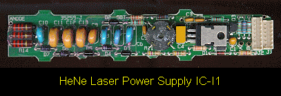
The He-Ne laser assembly from a barcode scanner is ideal for this purpose. It is compact, low power, usually runs on low voltage DC (12 V typical), and is easily disassembled to remount in a demonstration case. The only problem is that many of these have fully potted “brick” type power supplies which are pretty boring to look at. However, some have the power supply board coated with a rubbery material which can be removed with a bit of effort (well, OK, a lot of effort!).
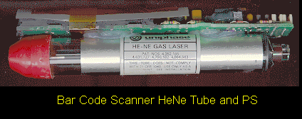
For example, this is from a hand-held barcode scanner. A similar unit was separated into its component parts:
The power supply includes the ballast resistors. These could easily be mounted in a very compact case (as little as 3″ x 6″ x 1″, though spreading things out may improve visibility and reduce make cooling easier) and run from a 12v DC, 1 A wall adapter. Used barcode scanner lasers can often be found for $20 or less.
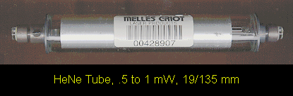
An alternative is to purchase a 0.5 to 1 mW He-Ne tube and power supply kit. This will be more expensive (figure $5 to $15 for the He-Ne tube, $25 to $50 for the power supply) but will guarantee a circuit board with all parts visible.
The He-Ne tube, power supply, ballast resistors (if separate from the power supply), and any additional components can be mounted with standoffs and/or cable ties to the plastic base. The tube can be separated from the power supply if desired to allow room for labels and such. However, keep the ballast resistors as near to the tube as practical (say, within a couple of inches, moving them if originally part of the power supply board). The resistors may get quite warm during operation so mount them on standoffs away from the plastic. Use wire with insulation rated for a minimum of 10 kV. Holes or slots should be incorporated in the side panels for ventilation – the entire affair will dissipate 5 to 10 Watts or more depending on the size of the He-Ne tube and power supply.
When attaching the He-Ne tube, avoid anything that might stress the mirror mounts. While these are quite sturdy and it is unlikely that any reasonable arrangement could result in permanent damage, even a relatively modest force may result in enough mirror misalignment to noticeably reduce output power. And, don’t forget that the mirror mounts are also the high voltage connections and need to be well insulated from each other and any human contact! The best option is probably to fasten the tube in place using Nylon cable ties, cable clamps, or something similar around the glass portion without touching the mirror mounts at all (except for the power connections).
Provide clearly marked red and black wires (or binding posts) for the low voltage DC or a line cord for AC (as appropriate for the power supply used), power switch, fuse, and power-on indicator. Label the major components and don’t forget the essential CDRH safety sticker (Class II for less than 1 mW or Class IIIa for less than 5 mW).
See:
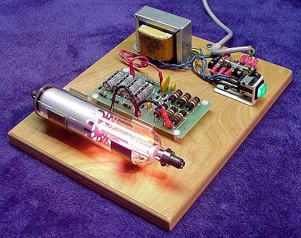
Above, as an example (minus the Plexiglas safety cover), contructed from the guts of a surplus Gammex laser (probably part of a patient positioning system for a CT or MRI scanner). The discrete line operated power supply is simple with the HV transformer, rectifier/doubler, filter, multiplier, and ballast resistors easily identified. This would make an ideal teaching aid.
See the suppliers listed in the chapter: Laser and Parts Sources.
The Ultimate Demonstration He-Ne Laser
Rather than having a see-through laser that just outputs a laser beam (how boring!), consider something that would allow access to the internal cavity, swapping of optics, and modulation of beam power. OK, perhaps the truly ultimate demo laser would use a two-Brewster tube allowing for interchangeable optics at both ends, be tunable to all the He-Ne spectral lines, and play DVD movies. 🙂 We’ll have to settle for something slightly less ambitious (at least until pigs fly). Such a unit could consist of the following components:
- One-Brewster He-Ne laser tube or head. This can be something similar to the Melles Griot 05-LHB-570 tube or the Climet 9048 head which contains this tube. These have a Brewster window at one end and an internal HR mirror with a 60 cm Radius of Curvature (RoC) at the other. Their total length is about 10.5 inches (260 mm).
- Adjustable mirror mount with limited range to permit easy mirror tweaking but with minimal chance of getting alignment really messed up. A basic design using a pair of plates with X and Y adjustment screws and a common pivot with lock washers for the compliance springs would be adequate.
- Interchangeable mirrors of RoC = 60 cm and reflectance of 98% to 99.5% (OC) and 99.999% (HR in place of OC to maximize internal photon flux). These may be salvaged from a dead 3 to 5 mW He-Ne laser tube. Those from a tube like the Spectra-Physics 084-1 would be suitable. It would be best to install the mirrors in protective cells for ease of handling.
- Baseplate to mount the laser and optics with the internal HR of the one-Brewster tube/head about 60 cm from the external mirror to create a confocal cavity – about one half of which is external and accessible. An option would be to put the external mirror mount on a movable slide to allow its position to be changed easily.
- Power supply with adjustable current and modulation capability. This would provide the ability to measure output power versus current and to use the laser as an optical transmitter with a solar cell based receiver.
- Plexiglas box to house and protect the laser and power supply (as well as inquisitive fingers from high voltage) with part of one side open to allow access to the internal photons.
Everything needed for such a setup is readily available or easily constructed at low cost but you’ll have to read more to find out where or how as each of the components are dealt with in detail elsewhere in Sam’s Laser FAQ (but I won’t tell you exactly where – these are all the hints you get for this one!).
A system like this could conceivably be turned into an interactive exhibit for your local science museum – assuming they care about anything beyond insects and the Internet these days. 🙂 There are some more details in the next section.
Guidelines for a Demonstraton One-Brewster He-Ne Laser
The following suggestions would be for developing a semi-interactive setup whereby visitors can safely (both for the visitor and the laser) adjust mirror alignment and possibly some other parameters of laser operation. The type of one-Brewster (1-B) He-Ne laser tube like the Melles Griot 05-LHB-570. Note that the 05-LHB-570 is a wide bore tube that runs massively multi (transverse) mode with most mirrors configurations unless an intracavity aperture is added. This is actually an advantage for several reasons:
- The multi-transverse mode structure is interesting in itself and provides additional options for showing how it can be controlled.
- Mirror alignment is easier and the tube will lase over a much wider range of mirror orientation.
- Output power is higher for its size and power requirements.
Here are some guidelines for designing an interactive exhibit:
- Mount the 1-B tube in a clear plastic (Plexiglas) enclosure with some ventilation holes to allow for cooling but make sure any parts with high voltage (anode, ballast resistors if not insulated) are safely protected from the curious. Provide a small hole lined up with the Brewster window for the intracavity beam. However, even if the B-window is at the cathode-end of the tube, don’t allow it to be accessible as the first fingerprint will prevent lasing entirely.
- Put the power supply in a safe place inside another clear plastic box if desired. I’d recommend controlling it with a time switch that will turn it on for perhaps 10 minutes with a push of a button. This is a tradeoff between wear from running the laser all the time and wear from repeated starts. Don’t forget the fuse!!!
- Orient the tube so the B-windows is either on the side or facing down. This will minimize dust collection and permit the rig to operate for many hours or days without the need for even dusting.
- Use an output mirror with an RoC from 50 cm to planar and reflectivity of 98 to 99.5 percent at 632.8 nm. The specific parameters and distance will affect the beam size, mode structure, and output power. A shorter RoC will limit the distance over which lasing will take place but will be somewhat easier to align.
- Use a decent quality mirror mount like a Newport MM-1 for the output mirror. Once it’s secured, arrange for the adjustment screws to be accessible to visitors but limit the range of rotation to less than one turn and mark the location of each screw where lasing is peaked. That way, no amount of fiddling will lose lasing entirely.
- The distance between the mirror and tube can be fixed or adjustable:
- For a fixed location, a distance of a few inches between the laser enclosure and mirror mount is recommended. This is enough space to install an aperture or Brewster plate. Or a hand to show that the beam is only present with the resonator is complete, not just a red light inside! But, it’s short enough that alignment is still easy.
- For added excitement, put the mirror mount on a precision rail to permit the distance to be varied from 0 to at least 45 cm from the B-window. Then, it will be possible to see how the mode structure changes with distance. This will depend on the RoC of the mirror as well.
- Another option is to provide various things like an iris diaphragm, thin wires and/or a cross-hair, adjustable knife edge, Brewster plate that can be oriented, etc. However, some care will be needed in making these useful without a lot of hand holding.
Weatherproofing a He-Ne Laser
If you want to use a He-Ne laser outside or where it is damp or very humid, it will likely be necessary to mount the tube and power supply inside a sealed box. Otherwise, stability problems may arise from electrical leakage or the tube may not start at all. There will then be several additional issues to consider:
- Heat dissipation – For a small He-Ne tube (say 1 mW), figure this is like a 10 to 15 W bulb inside a plastic box. If you make the box large enough (e.g., 3″ x 5″ x 10″), there should be enough exterior surface area to adequately remove the waste heat.
- Getting the beam out – A glass window (e.g., quality microscope slide) mounted at a slight angle (to avoid multiple reflections back to the He-Ne tube output mirror) is best. However, a Plexiglas window may be acceptable (i.e., just pointing the laser at a slight angle through the plastic case). A Brewster angle window should be used only if the He-Ne tube is a linearly polarized type (not likely for something from a barcode scanner) and then the orientation and angle must be set up for maximum light transmission.
- Condensation on the optics and elsewhere – This may be a problem on exposed surfaces if they are colder than the ambient conditions. Let the entire laser assembly warm up before attempting to power it up!
