Now it’s time to dig into the main contactor pack from the hybrid battery I tore down in a previous post. This unit contains the main output relays, precharge components, current measurement & protection. It’s pretty heavy, which isn’t surprising when you realise how much copper there is in this thing! Manufactured by Lear Corporation in the US, this is a seriously heavy duty piece of electrical engineering.
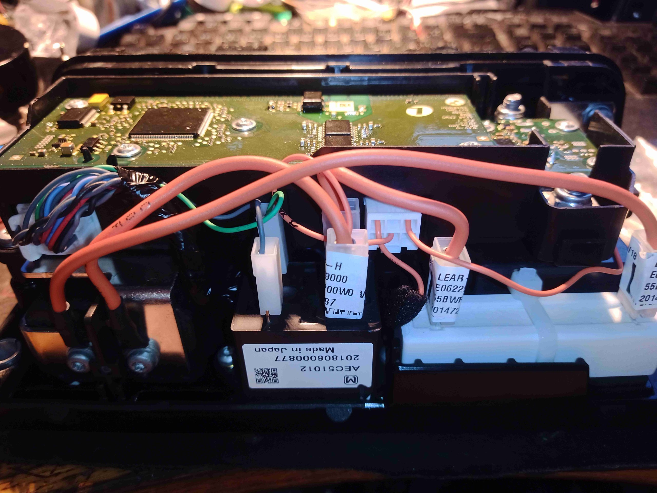
Once the cover is popped off, the first thing is a large PCB on the top, and some low current wiring. Not much to see yet.
The main control & current measurement PCB is on the top of the unit, in a plastic frame. This is a complex arrangement in itself. Unfortunately I’ve not been able to identify any of the main components on here, as everything is conformal coated, so the numbers are obscured!
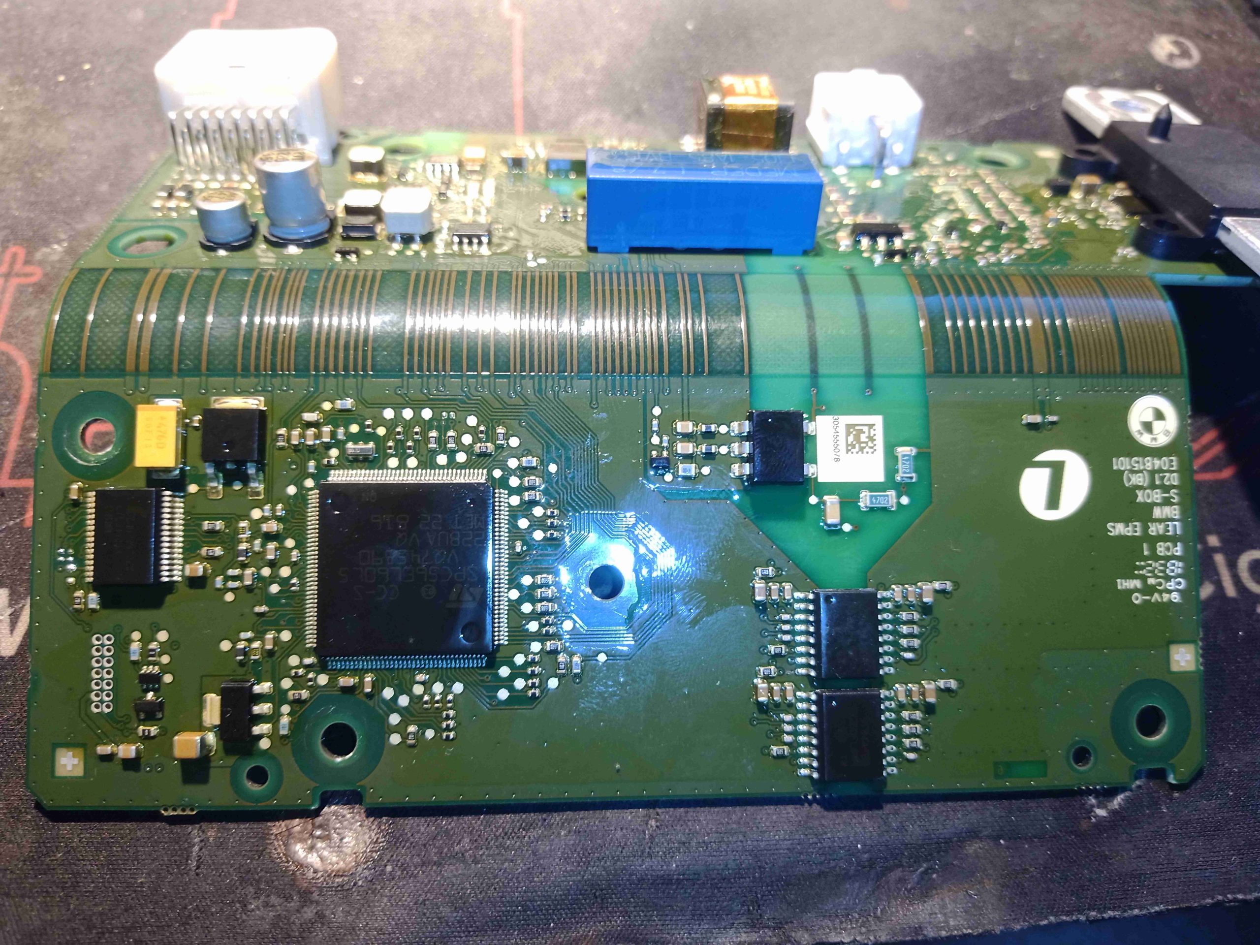
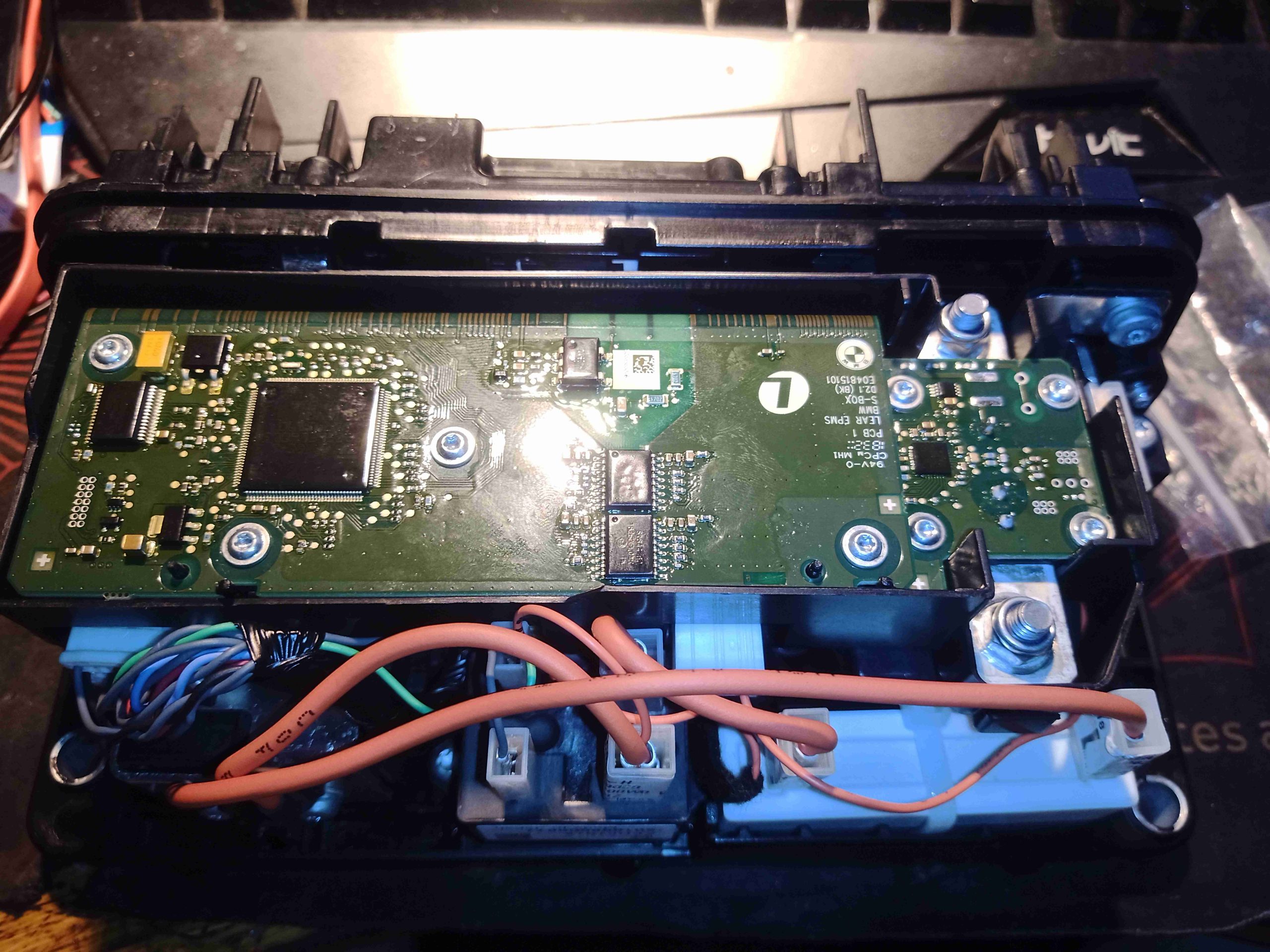
Removing the assembly from it’s plastic frame reveals a flex-rigid assembly, which is normally folded in half. The main CPU is on the top layer, and most of the power supply & measurement electronics on the bottom. There’s some serious isolation here on the right as well.
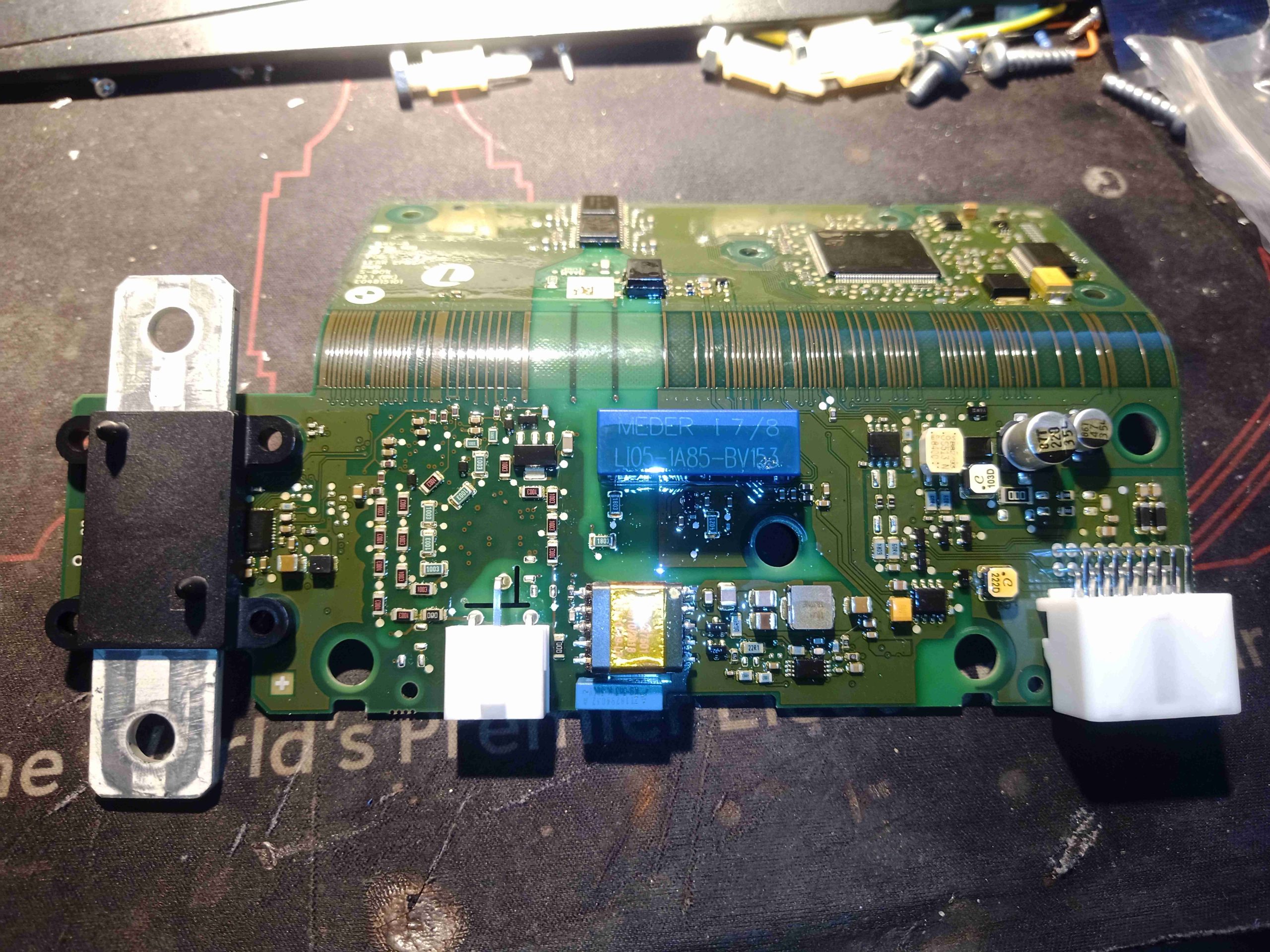
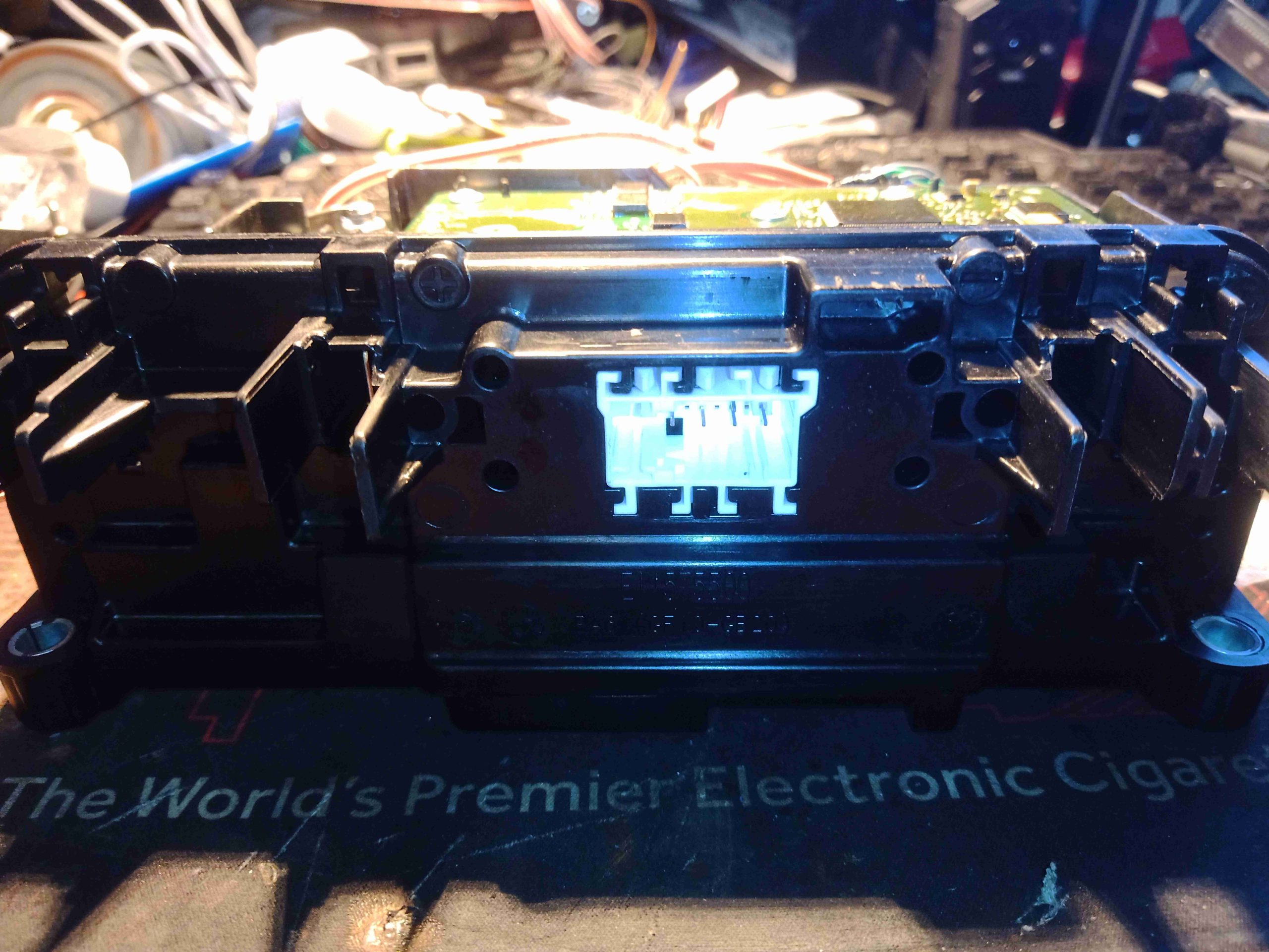
The bottom has the connectors, and some power supply components. The main current shunt is on the left, this would be in the negative return side of the main battery bus.
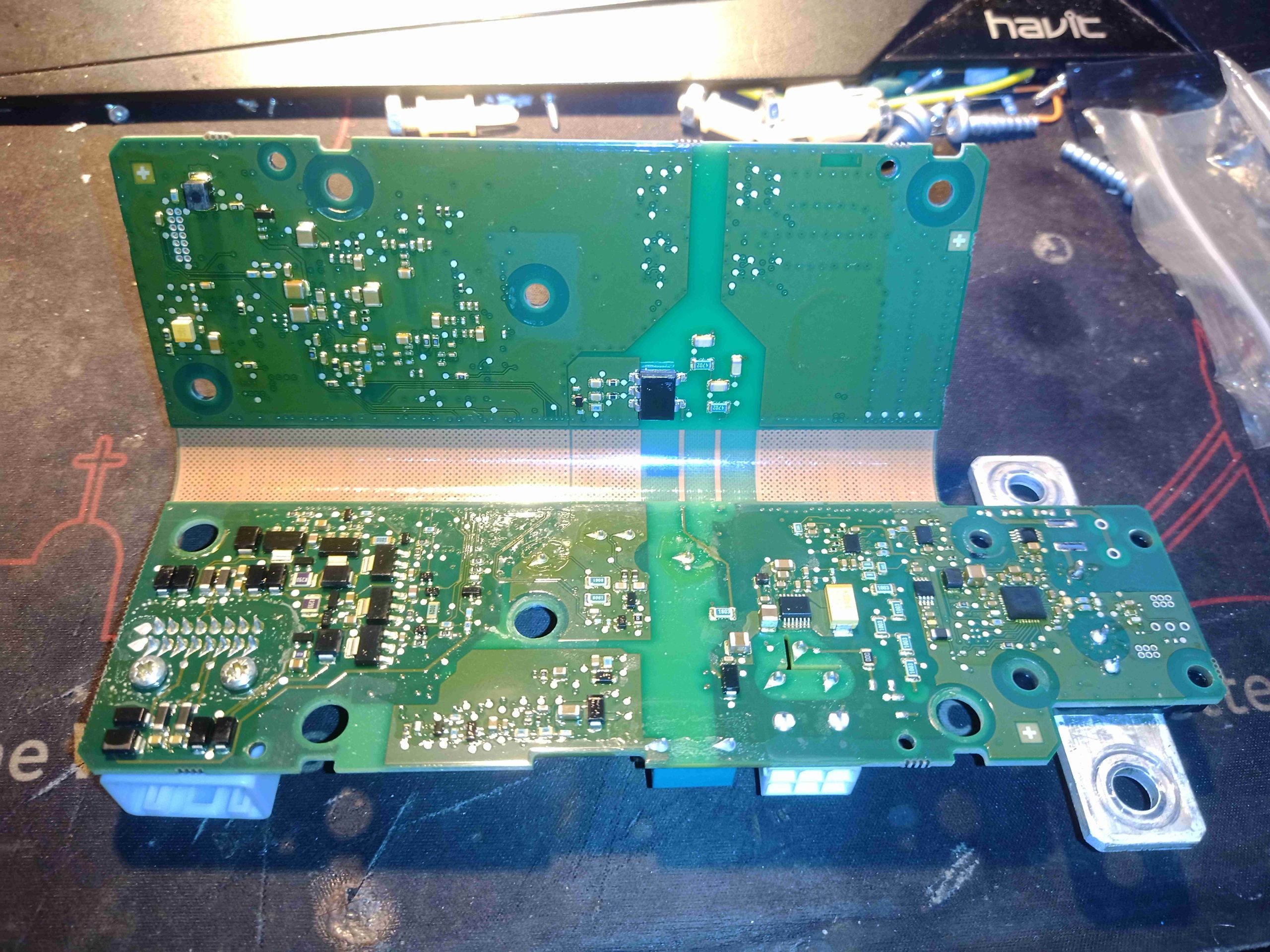
Not much on the backside of the assembly, apart from a few transistors & passives.
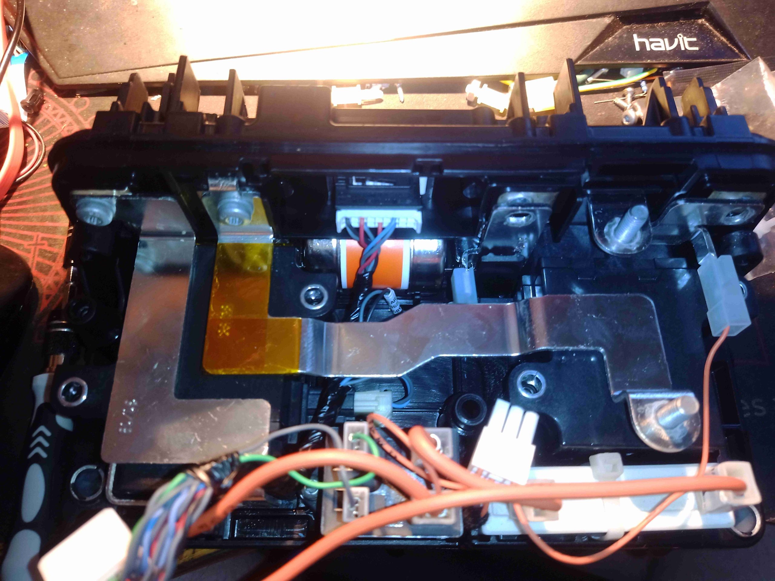
Once the control PCB assembly is removed from the main frame, the high current bus bars become visible. There are 3 switching devices in here, two for the main battery bus, and a smaller one for the precharge function. There’s also a main fuse hiding in the middle.
The main battery positive contactor is tucked in on the left side, with the precharge leads across it’s contacts. This normally isolates the car from the batteries when open.
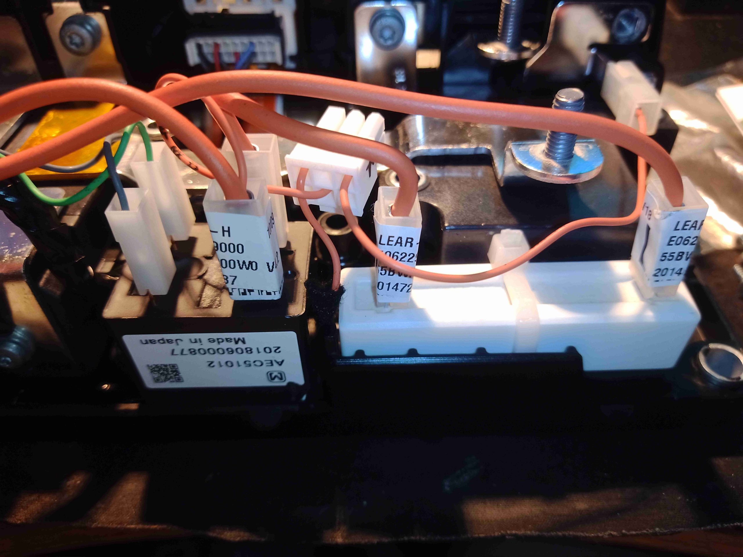
Precharging is dealt with by this collection of components. A smaller relay, and a large ceramic 15Ω resistor limit the current that can be drawn when the vehicle is enabled. Closing the main contactors first would potentially cause damage due to the enormous inrush currents caused by the large filter electrolytic capacitors in the traction inverters.
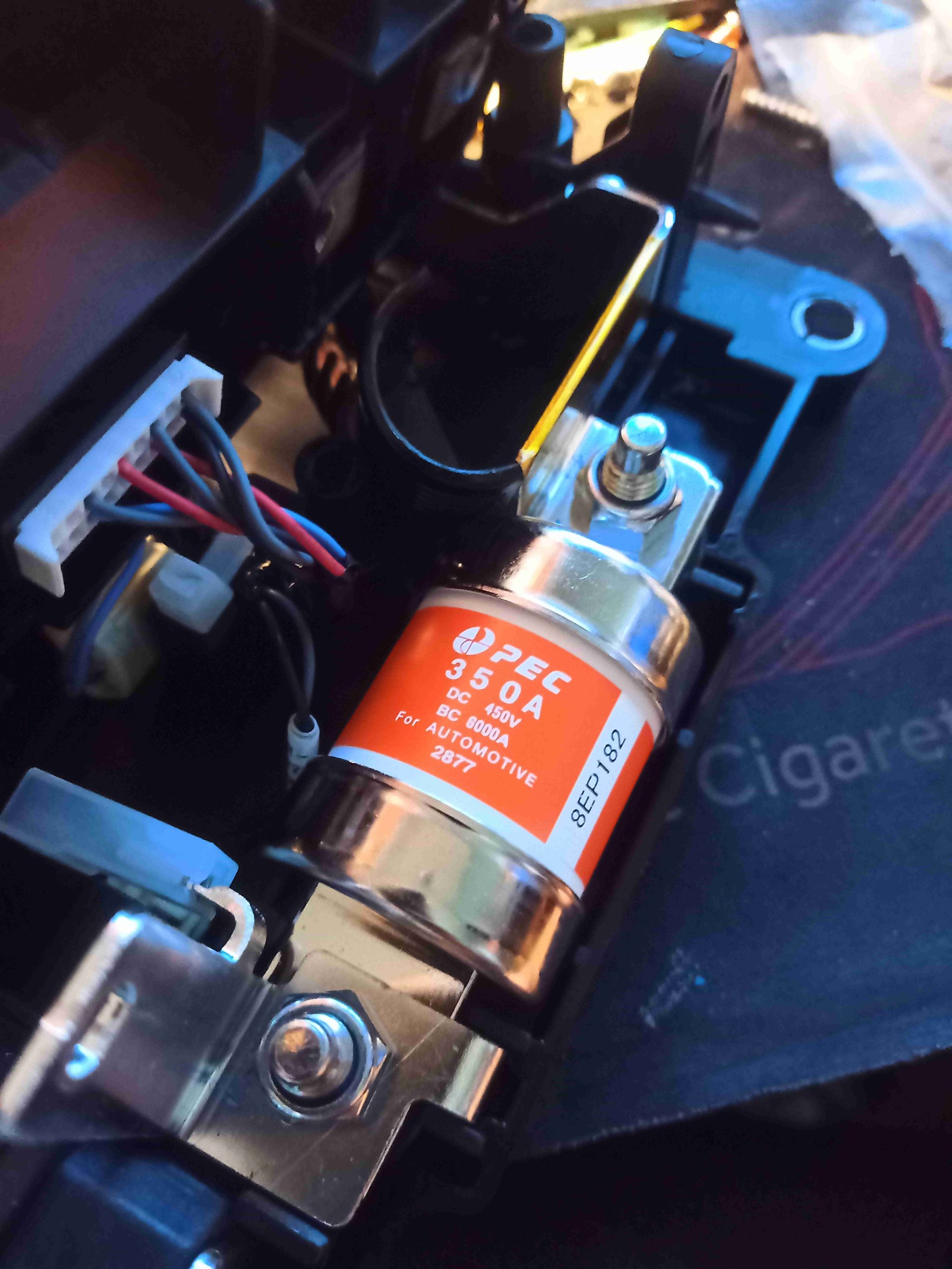
The main battery fuse, in the DC + line from the cell modules is a 350A rated unit, 450v DC. Being a HRC type, this is capable of breaking 6kA under fault conditions.
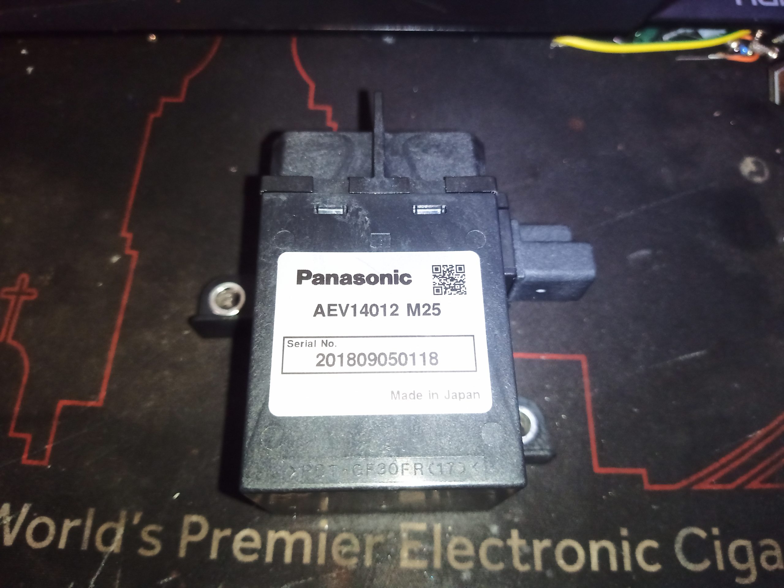
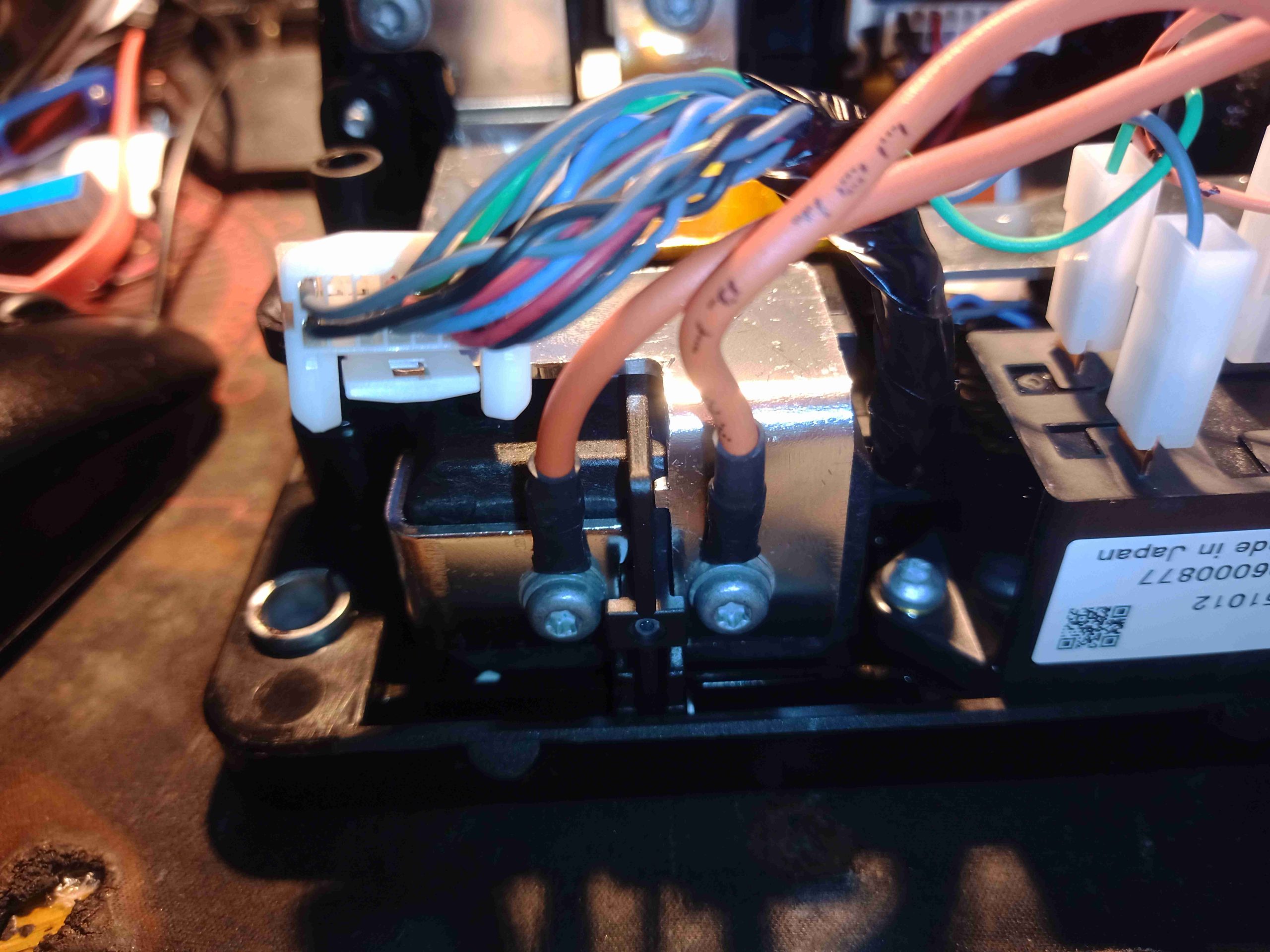
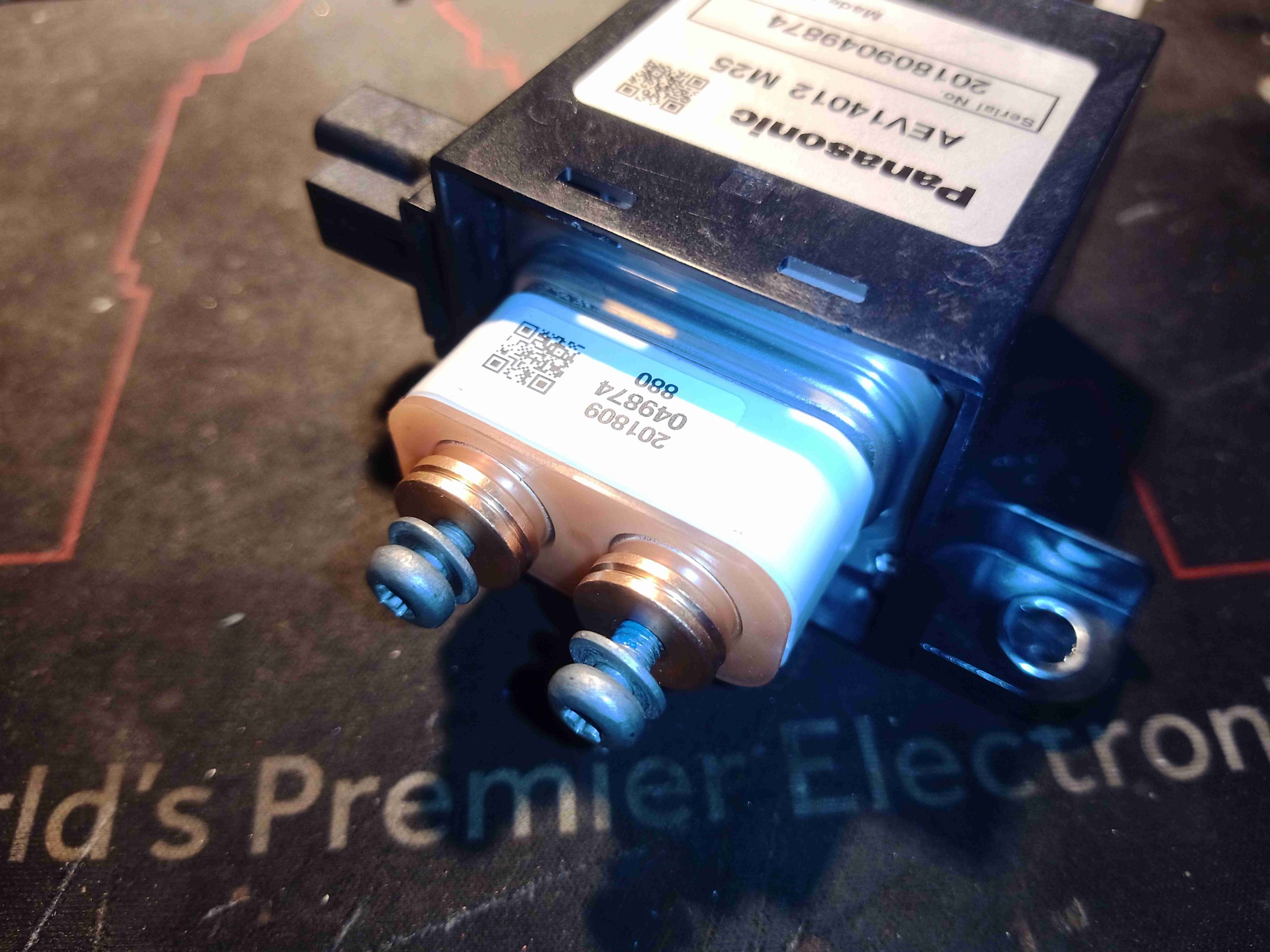
Here’s one of the pair of main contactors, Panasonic AEV14012 400v DC, 120A rated units. These are serious devices, having a hermetically sealed ceramic capsule around the contacts, and a Hydrogen filling!
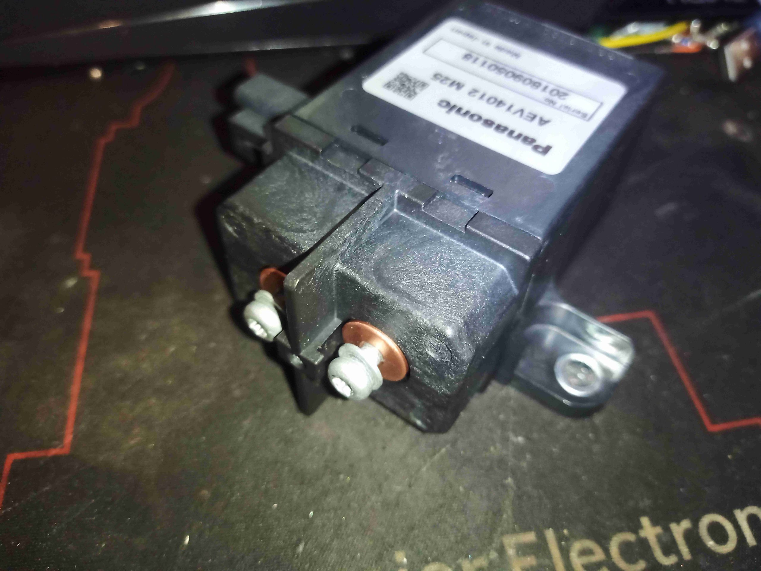
Connections are made via big copper slugs, with M4 screws in the ends. There’s a barrier between them to protect against flashover.
Pulling the top plastic cap off reveals the ceramic capsule containing the contacts. This is the Hydrogen filled space of the contactor. The reason for the hydrogen fill is arc quenching.
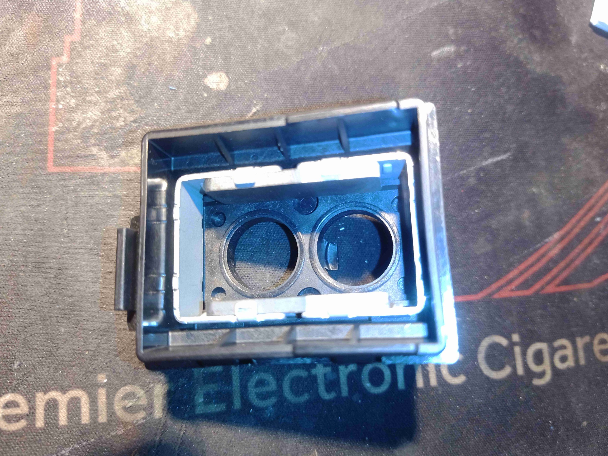
The contact capsule sits in a permanent magnetic field, provided by these small ceramic magnets. These assist in pulling any arc towards the ceramic walls of the contact capsule, helping to cool & extinguish it.
