Description
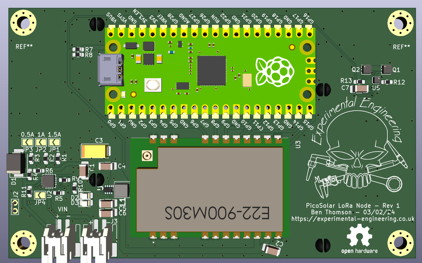
This is a Raspberry Pi Pico powered 868-915MHz LoRa node.
The board has connections for a Lithium Ion / Lithium Polymer battery and supports being powered from multiple sources:
- Solar Panel
- Basic DC Input
- USB (Pico port) – the Pico USB port is intended primarily for programming, and serial debugging. Depending on the cable used, RF transmit level and the capability of the power supply, insufficient power may be transferred to successfully power the module fully if batteries or an alternative DC power source is not used in tandem.
The onboard charge controller can be set to three different charge current levels via solder jumpers on the PCB (0.5-1.5A).
There is also an optional connection for a 10K thermistor, to monitor battery temperature. This is important in a cold outdoor application, where the battery temperature may dip below 0°C.
The LoRa radio module supports EU & US frequency bands (850-950MHz), and has a maximum transmit power of +30dBm (1W).
Notes for Power Supplies
At maximum transmit power (30dBm), this module will draw approximately 900mA from a 5V supply – insufficient supply capacity, or poor quality batteries can cause supply brownouts and crashes of the Pico microcontroller.
At minimum input voltage from batteries (3V), this current will increase to around 1.7A due to the onboard DC-DC converter powering the radio module. Again, good quality batteries or local power supply are essential. It is recommended that batteries are always used in conjunction with a solar or DC input, to ensure PSU stability at the higher transmit power levels.
Battery Charging and Protection
The onboard linear battery charger is configurable via jumpers for different charging currents and modes, to suit either solar or DC charging.
Two LEDs are provided for status indication of the charger:
- D1: Battery is charging
- D2: Valid input source detected
Two options are provided for battery power, both can be managed with the onboard charger:
The onboard 18650 battery holders are connected in parallel, and fully protected against overvoltage, undervoltage, and overcurrent. Ensure that the two cells used are of identical manufacture, capacity, age and internal resistance.
It is CRITICAL that the polarity markings on the PCB are taken note of for the 18650 battery holders – there is NO polarity protection onboard as this would prevent the battery charger from operating. Fitting the batteries backwards will result in permanent board damage.
The external battery connector is unprotected – this is intended for connection to an already protected external 3.7V battery pack.
It is possible to use both onboard batteries and external batteries, provided they are identical. Connection of mismatched batteries in any configuration may cause damage or fire.
The VIN connector will accept any DC supply voltage between 5-10.5V before the charger shuts down in self-protection mode.
RF Output Routing
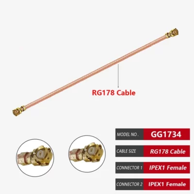
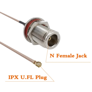
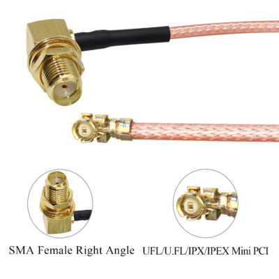
Due to the high output power capability of this module, if being used at the higher power settings (>100mW (20dBm)), careful consideration needs to be given to the routing of the coax cable off the module, keeping it as far away from the power supplies and microcontroller as possible.
Avoid running the coax directly over ICs.
The antenna should not be placed within direct proximity of the module to prevent interference with the Pi Pico.
Adding Sensors and Accessories
The I²C bus is unused on this board, permitting full use for external sensors and displays. The onboard 5V power supply can be tapped for a regulated rail, as can the 3v3 rail, direct from the Pi Pico.
Setting Output Power
Due to the integrated RF Power amplifier, the actual RF power setpoint in Meshtastic should be set to a much lower level than you’d expect:
For 500mW (27dBm – Legal MAX in EU/UK), set LoRa TX power to 17.
For 1000mW (30dBm – Legal MAX in USA), set Lora TX power to 22.
Please see below for typical output power vs firmware setting of output power:
| SX1262 Power dBm | Module Power dBm | Calculated Gain dBm |
|---|---|---|
| +1 | +8.11 | +7.11 |
| +2 | +09.25 | +7.05 |
| +3 | +09.91 | +6.91 |
| +4 | +10.71 | +6.71 |
| +5 | +11.90 | +6.90 |
| +6 | +12.87 | +6.87 |
| +7 | +13.86 | +6.86 |
| +8 | +14.90 | +6.90 |
| +9 | +16.04 | +7.04 |
| +10 | +16.97 | +6.97 |
| +11 | +17.95 | +6.95 |
| +12 | +18.99 | +6.99 |
| +13 | +20.00 | +7.00 |
| +14 | +20.97 | +6.97 |
| +15 | +21.99 | +6.99 |
| +16 | +23.48 | +7.48 |
| +17 | +24.35 | +6.94 |
| +18 | +24.94 | +6.94 |
| +19 | +25.64 | +6.64 |
| +20 | +26.73 | +6.73 |
| +21 | +28.75 | +6.75 |
| +22 | +29.37 | +7.37 |
Directly compatible with firmware written to use the Waveshare Pico-LoRa SX1262 board.


Reviews
There are no reviews yet.