Well it was only a matter of time until we had a major failure of the onboard hydraulic system on board the boat, and this weekend proved to be that point in time.
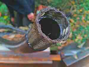
Hose End
This is what remains of one of the main hoses to the propulsion motor, the fitting has been blown off the end of the hose! This occurred when I moved into reverse to stop the boat for oncoming traffic, and suddenly I lost all drive. The end result is a bilge filled with hydraulic oil, and zero power for manoeuvring.
The hose outer cover has been cut through by the fitting, like it had been sliced through with a knife, what remains of the inner liner & outer sheath is still in the fitting:
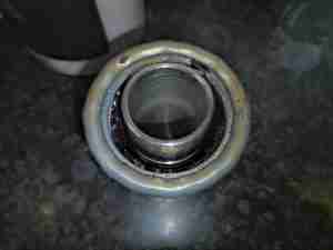
Fitting
Here’s the end of the offending fitting, with the remains of the hose. I suspect this termination wasn’t done correctly in the first place – either the swage was done too tight, cutting into the hose, or the fitting was never pushed all the way onto the hose before swaging, resulting in reduced strength.
Now comes the effort of cleaning out the roughly 40L of oil now in the bilges, refilling the oil tank & getting new hoses made up.
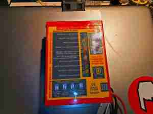
Here we have another piece of tech from Sterling Power – this is their Advanced Alternator Regulator, the Pro Reg D. Since I’m rejigging the alternator setup onboard, I figured I’d do a little teardown.
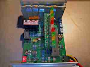
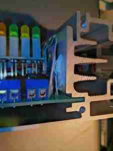
Cover Removed
Removing the top cover reveals the main PCB, which is slotted into the Aluminium heatsink extrusion. It’s a pretty well packed board, with both sides packed with tracks. There’s a small fan at the top of the unit, to keep the heatsink cool, but this has never worked for as long as this regulator has been in service.
Thermistor
Here would be the reason the fan has never operated – the thermistor which is supposed to monitor the temperature of the heatsink the MOSFETs are clamped to isn’t even in contact with it. Simply glopped with heatsink compound & stuck behind the SIL pad. This is a little sloppy to say the least, and should be in close thermal contact with the heatsink. I’ll have to adjust this mounting.
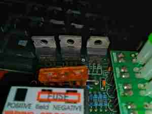
Field Control MOSFETs
Removing the heatsink shows the main field control FETs, both a P-Channel IRF4905 74A for positive field control, and a N-Channel IRF1010E 84A for negative field control. These are selected by moving the blade fuse between 3 spade terminals. Incedentally, Automotive-type blade fuses are not quick enough to protect semiconductors in the event of a serious fault, the likely result being an intact fuse & totally blown MOSFET. Nevermind.
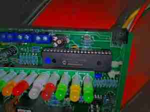
Microcontroller
The unit is controlled by a Microchip PIC16F874, in a large package. There’s a couple of trimmers onboard for tweaking the calibration of the regulator, along with a dual DIP switch & a 12/24v link. Display is taken care of by a large row of indicator LEDs on a mezzanine board, there’s also a 4-pin Molex connector for a remote status display.
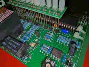
LED Board Mounting
The LED board is mounted to the main PCB with long pin headers, with no other support. Given the naturally vibrational nature of boats & their engines, having solder joints flapping about in the breeze isn’t a great plan, and fatigue is likely to set in here before long.
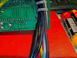
Loom Damage
Speaking of vibration, since the cable loom emerging from the aluminium case of the regulator is totally unprotected, the sharp edge of the extrusion has already begun chewing through the insulation! This has occurred after about 50 hours running time since the unit was installed. I’ll add a sleeve over the loom where it pops out of the corner to protect things better. Having the earthed aluminium casing munch it’s way through the insulation & short the entire loom out would not be a great result.
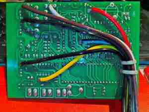
PCB Reverse
While I’ve got the board out of the casing, I’ve applied a heavy coat of PCB conformal coating to the back to help keep the moisture out, once everything is back together the top of the PCB will get the same treatment after masking off the parts that wouldn’t take kindly to a blasting with conformal coating.
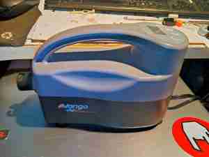
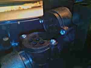
Here’s another piece of tech, the electric air pump that’s available as an optional extra with Airbeam tents. I expected this to be a centrifugal blower, but instead it’s a large reciprocating air compressor – even if the construction quality is a little dubious for a device that costs over £70.
Pump Section
The internal parts of this pump are almost entirely made of plastic – not what I’d expect for an air compressor.
Valves
The valves are located on the end of the cylinder, the right hand on is the intake valve, the right is an pressure relief valve. The outlet valve is hidden inside the tube.
Drive Motor
The drive motor has the same model number as the overall pump, likely made specifically for this unit. This motor does have some cooling from a fan on the armature.
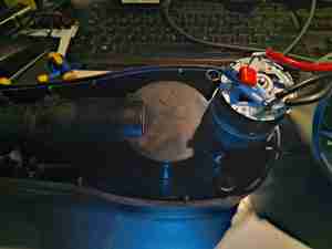
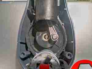
Crankshaft
After the cover has been removed from the pump unit, the main drive is visible. The driven gear is made of plastic, most likely nylon. The motor pinion is of brass. Ball bearings are used on the crank gear, but it appears that the big end bearing is a simple bushing on the steel pin.
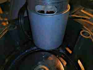
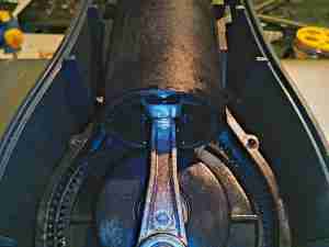
Plastic Piston
The working cylinder & piston are also made of plastic, so I don’t hold up much hope of this unit wearing well, even though the plastic feels like Nylon 66, glass fibre reinforced. Plenty of grease has been applied to the moving parts at least, to help keep the friction down. The 20 minute limit on operating time most likely has a lot to do with the almost entirely plastic construction – the adiabatic heating of the air as it’s compressed will make short work of the relatively low melting point of the Nylon.
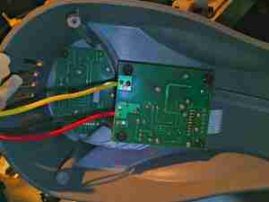
Electronics Section
The electronics are on a pair of PCBs tucked into the upper cover, one dealing with the pressure measurement, microcontroller & power control, and the other dealing with the display & buttons.
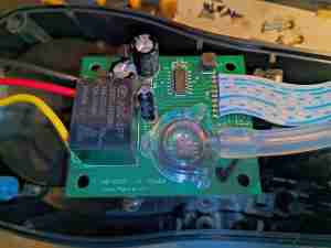
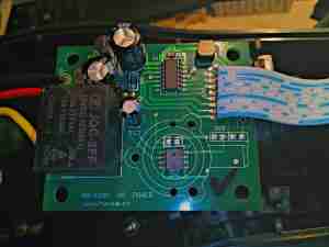
Power Control Board
The power control board has a 10A relay to switch power to the motor, along with a small microcontroller & pressure sensor, which is under the plastic adaptor on the PCB.
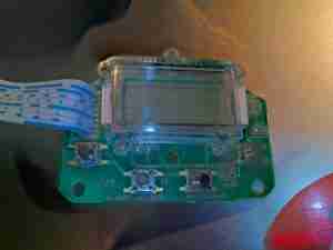
Display Board
The display is a standard 7-segment LCD, with a zebra strip connection to the PCB. Underneath hides the LCD controller itself. I’m not going to take this one off, as zebra strips don’t usually work properly once removed.
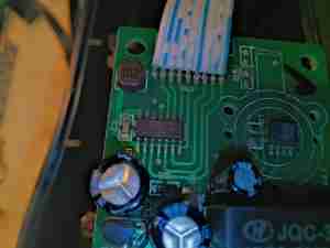
Microcontroller
The microcontroller is an Atmel ATTINY24A with 2K of onboard flash. The pressure sensor is on the right, although I haven’t been able to decode the laser-etched number on the top. Power is handled by a small linear regulator at the bottom edge of the board, with a couple of large electrolytics for filtering.
Power Control Board
Here’s an overall view of the power control board, with a better view of the pressure sensor & relay. This also gives a hint to the actual manufacturer of the pump – with the model number HB-630A. Since this unit is rated by their own admission at 13.5A, the 10A relay is likely to take a real beating over time. I measured 11A current draw at 7PSI output pressure.
Tip Jar
If you’ve found my content useful, please consider leaving a donation by clicking the Tip Jar below!
All collected funds go towards new content & the costs of keeping the server online.