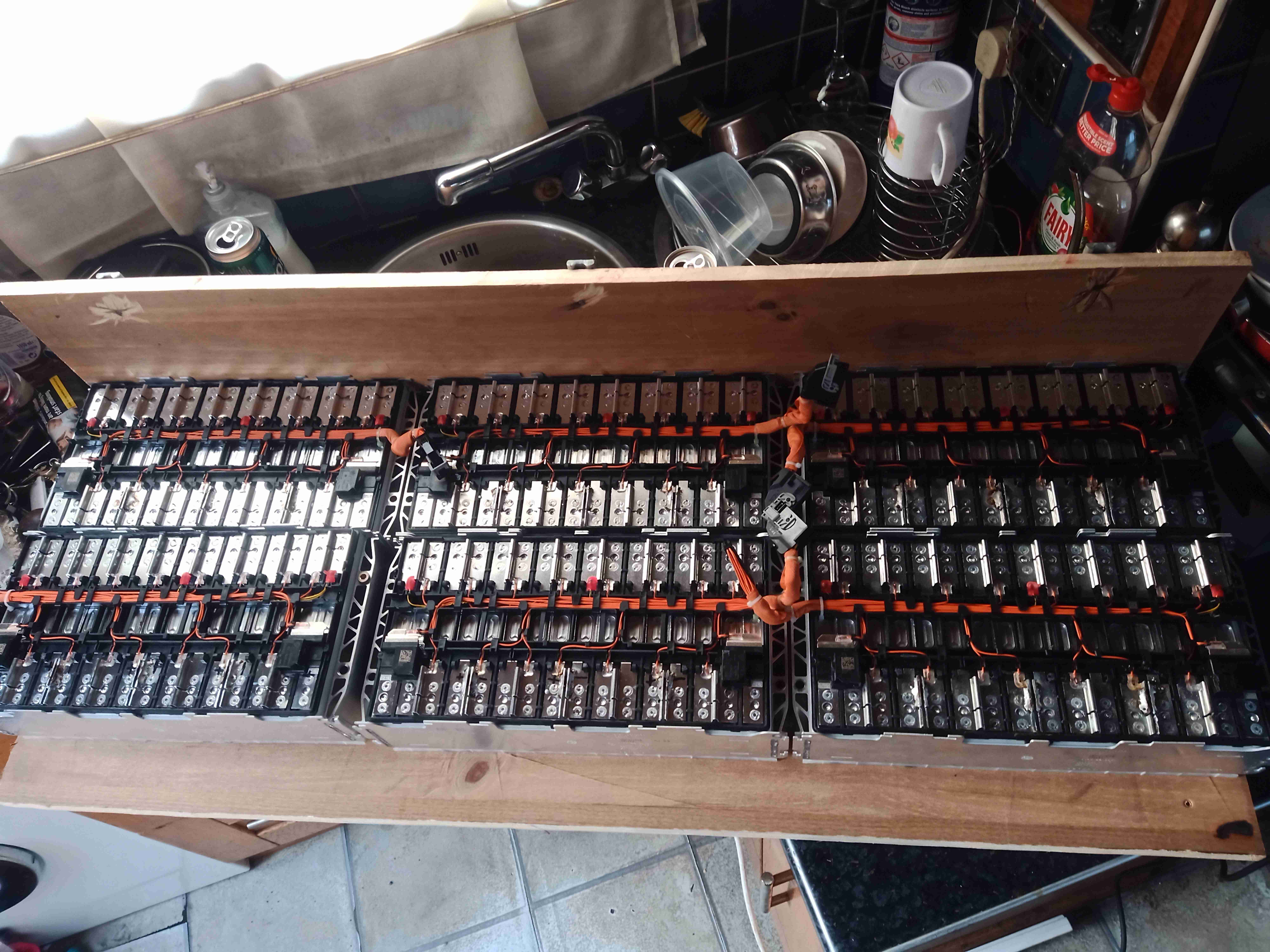
Now the cell modules have been removed from their original home, it’s time to get them repurposed! A custom mounting board has been constructed from timber, and the modules mounted on them. To say this assembly is heavy would be an understatement – it’s barely a two-man lift!
As assembled in the car, the pack as 96S1P, with every cell in series. As we need a low voltage bus, the modules have been reconfigured for 4S4P, in total this makes 4S24P with all 6 modules bussed together. As the cell interconnects are laser welded, some ingenuity was required here.
It turned out the best method (and the safest, to avoid any swarf shorting out cells!), was to use a grinder to cut off the top of the loop on the aluminium interconnects, separating them.
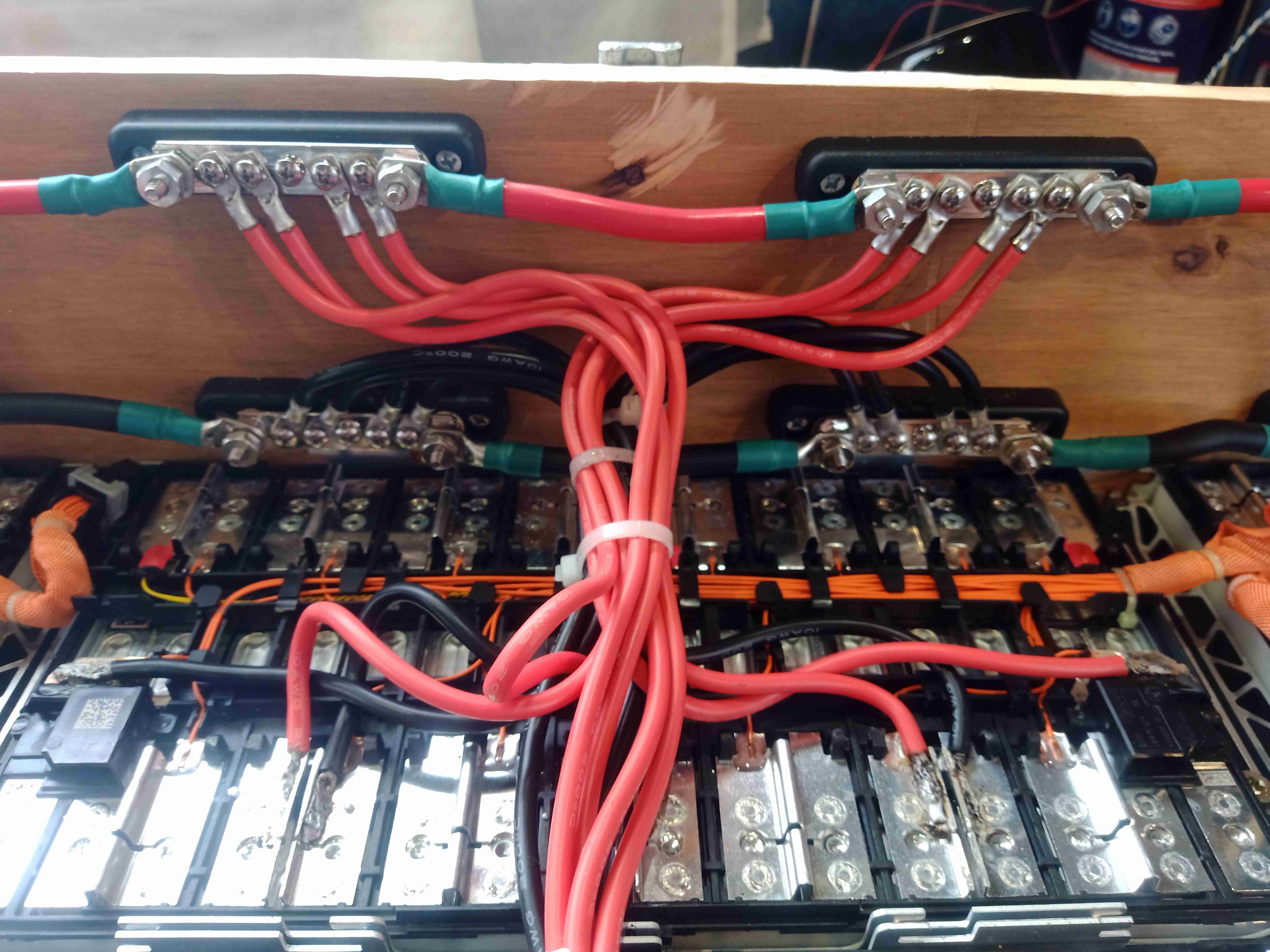
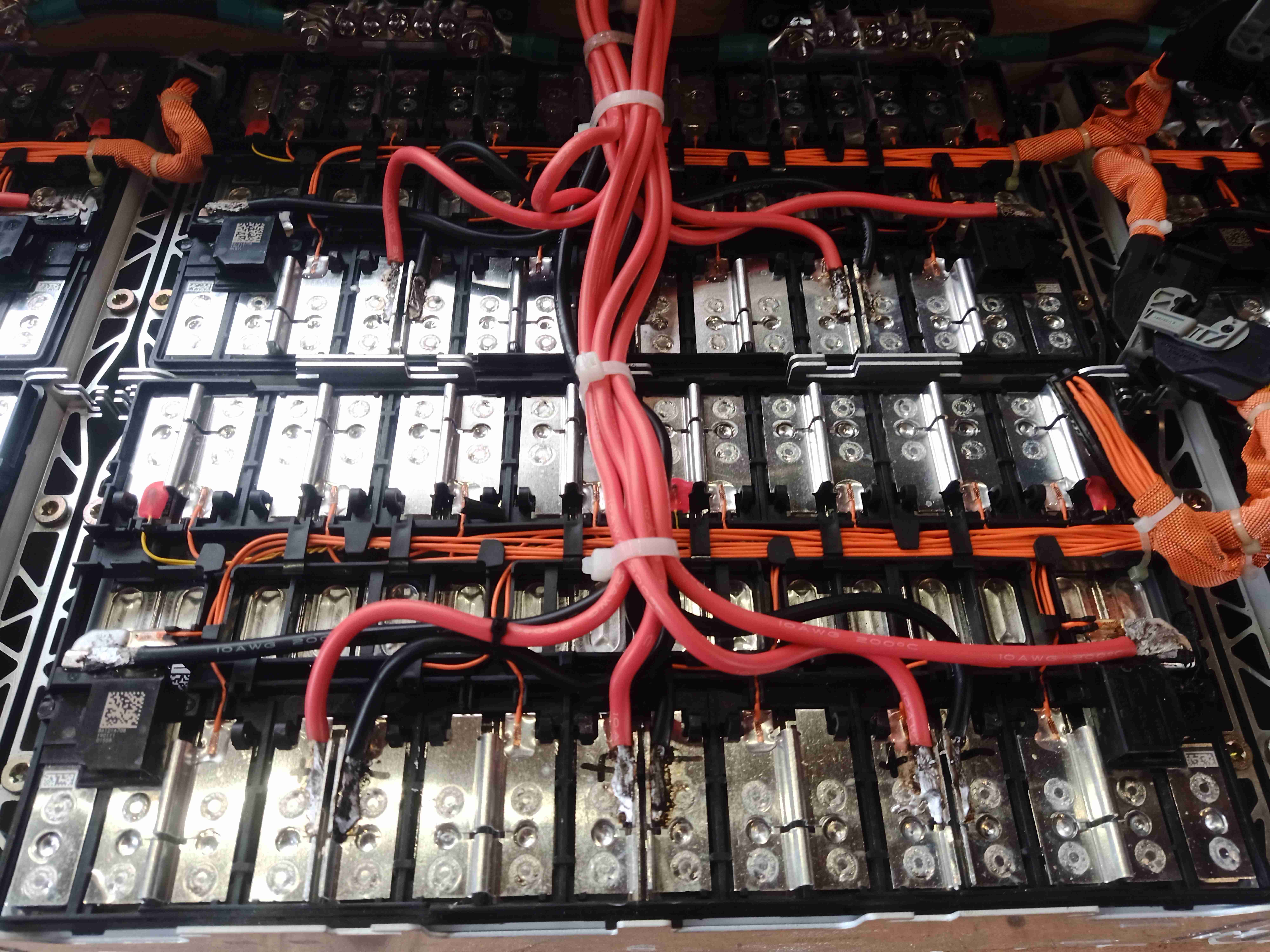
Battery Bus Links
12 5-way bus bars have been installed on the board, and 25mm² cable links them together. To get the angry pixies from the cell modules, 8mm² flexible silicone cable has been used, 4 links to a bus bar. This setup should provide more than enough current capacity.
Cell Connections
Here can be seen the cell interconnects – and the grinder cuts to separate them where required to break the module up into 4S strings. As the interconnects are Aluminium, special solder was required to get the copper cables soldered down, in my case I used Alusol 45D solder, which contains a very active flux capable of stripping the oxide from the Aluminium.
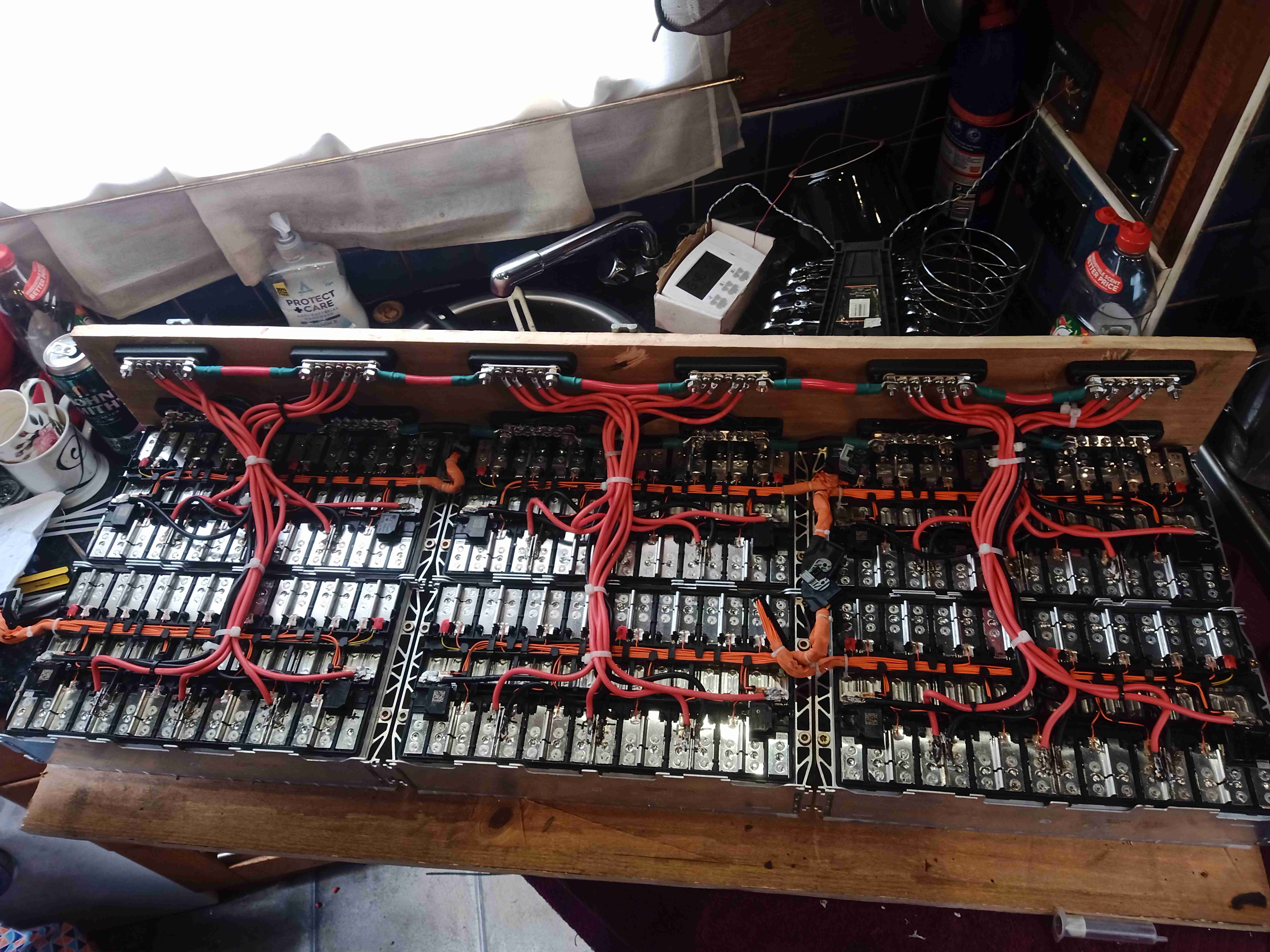
Batteries Wired
Finally, here is the new pack, all connected together. All that needs to be done now is the balance wiring loom, which will allow the BMS to sense each cell voltage individually, and connection of the BMS, Coloumeter & fuses, this will all be covered in a future post!
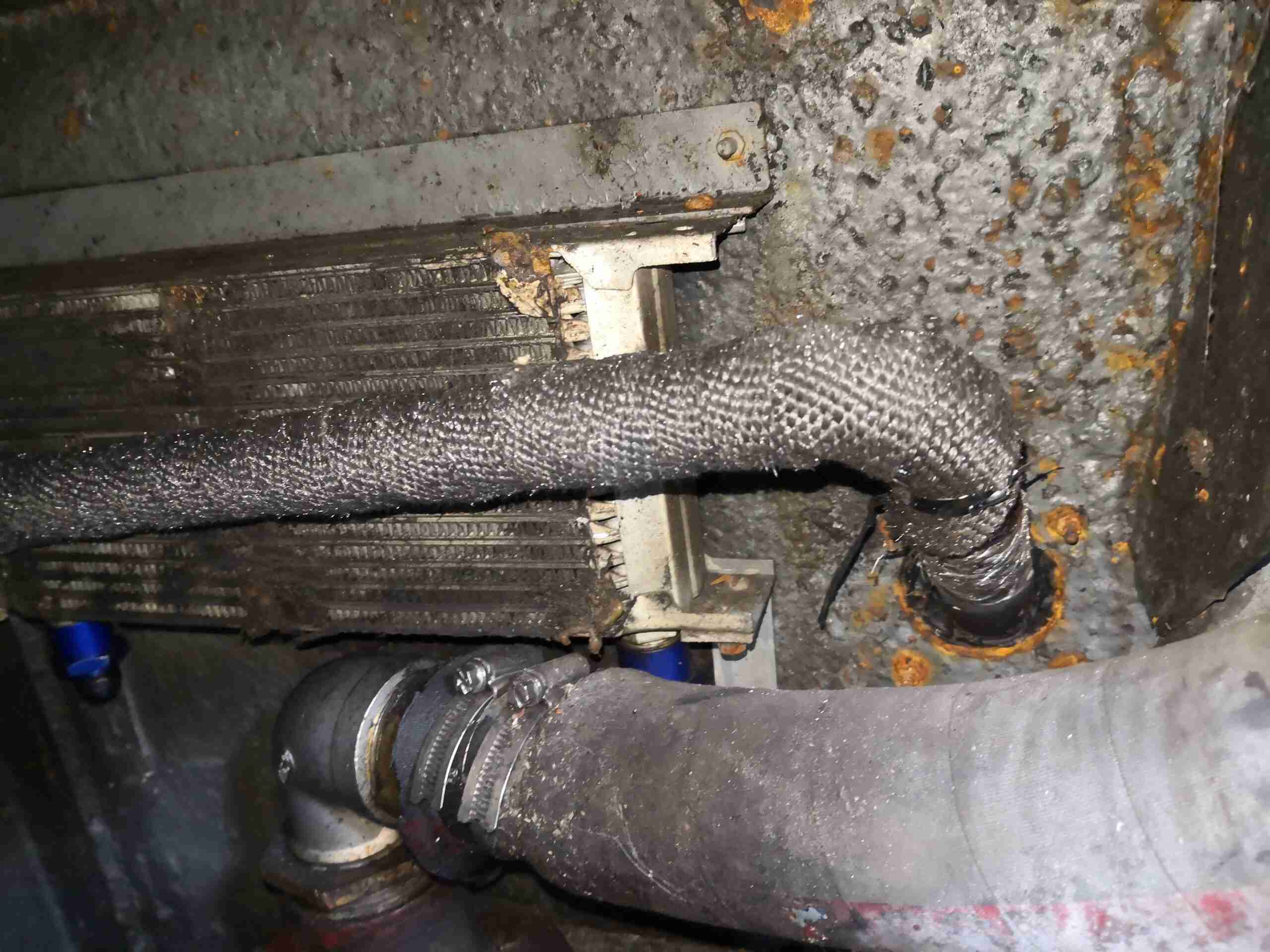
Since rebuilding the burner for the Webasto water heater on board nb Tanya Louise, I figured it was about time I sorted the exhaust out as well. The standard Eberspacher / Webasto type exhaust system components are shit. Nothing is properly gas tight, no matter how you build the system, due to how the pipe is constructed – it’s spiral ribbed stainless flexi tube, and even proper clamps don’t exert enough force to create a gas seal on the fittings, leaving gaps in the spiral for exhaust to leak out. Unfortunately I don’t have a photo of the old exhaust setup – it was however awful.
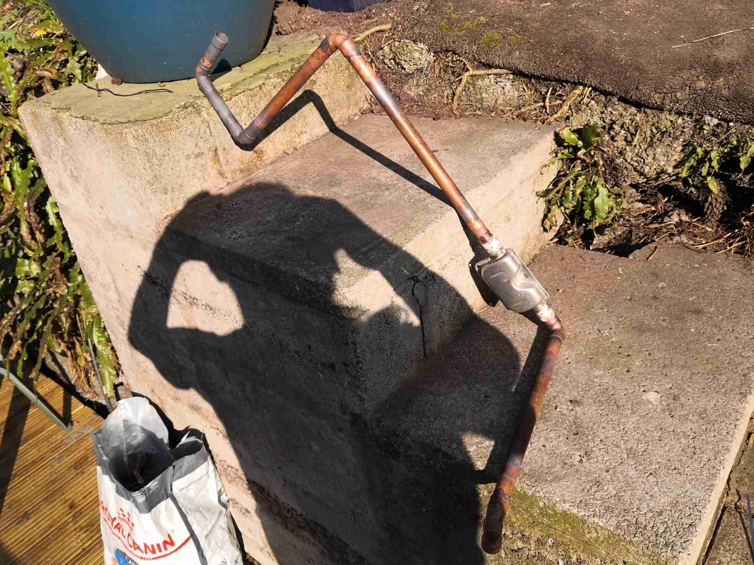
So to fix the problem of the messy setup, and to fix the issue of leaking exhaust gases, I got to work creating a custom system from 22mm copper pipe, brazing all the joints together.
Completed Exhaust
Here’s the completed system, matched to the location of the heater unit in the engine bay, and the exhaust skin fitting. The ends of the pipe are expanded with a hydraulic tool to allow them to fit onto the heater & skin fitting, these being too large for 22mm pipe normally.
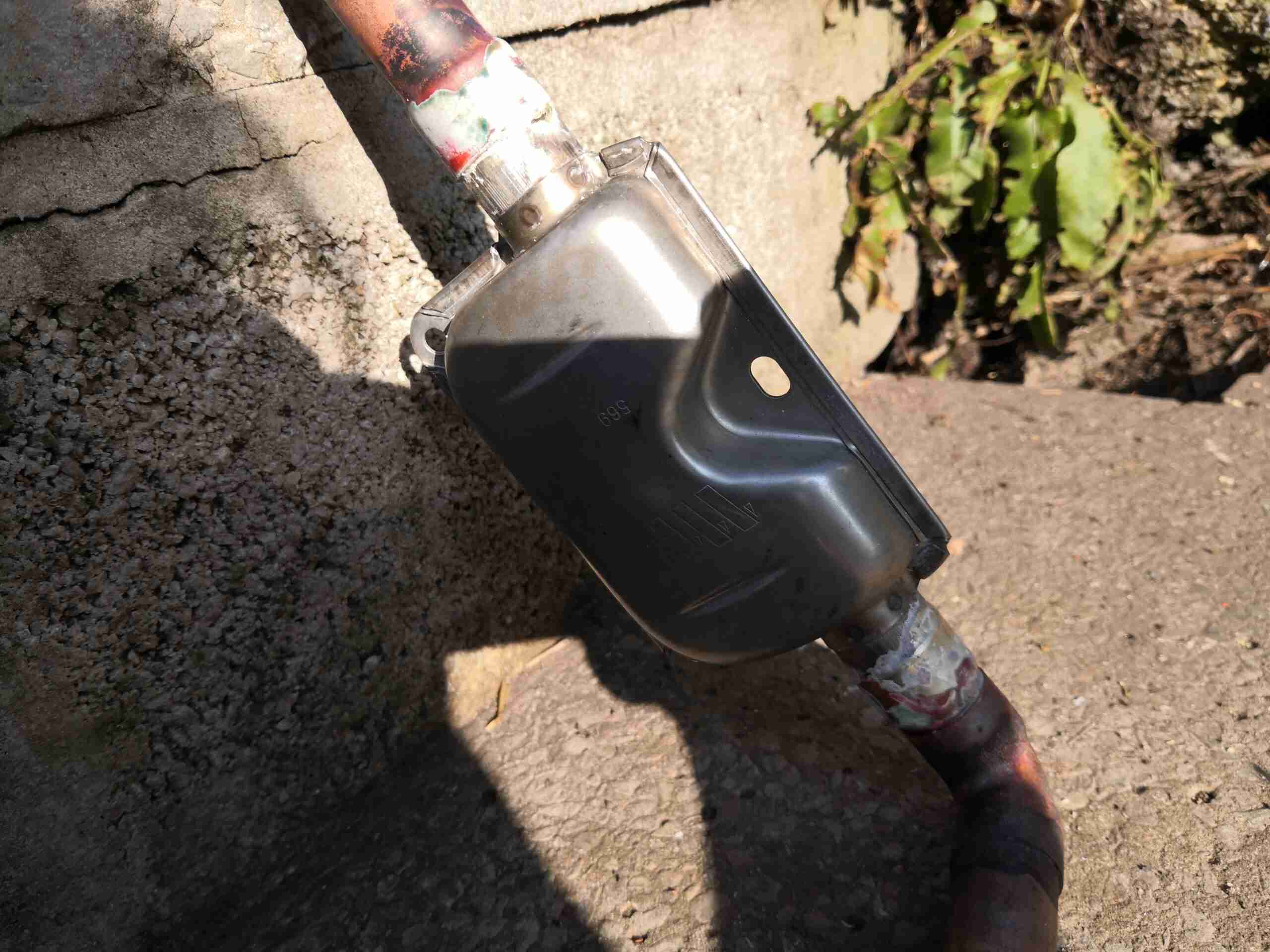
Brazed Muffler
The muffler is also fully brazed to keep exhaust gases inside the exhaust. These are supplied just crimped together as they’re intended for use under vehicles. A sealed marine grade exhaust silencer is available, but very expensive. Again the copper pipe ends are expanded with the hydraulic tool to allow them to fit into place on the stainless tails. Brazing was done with 55% silver brazing rod.
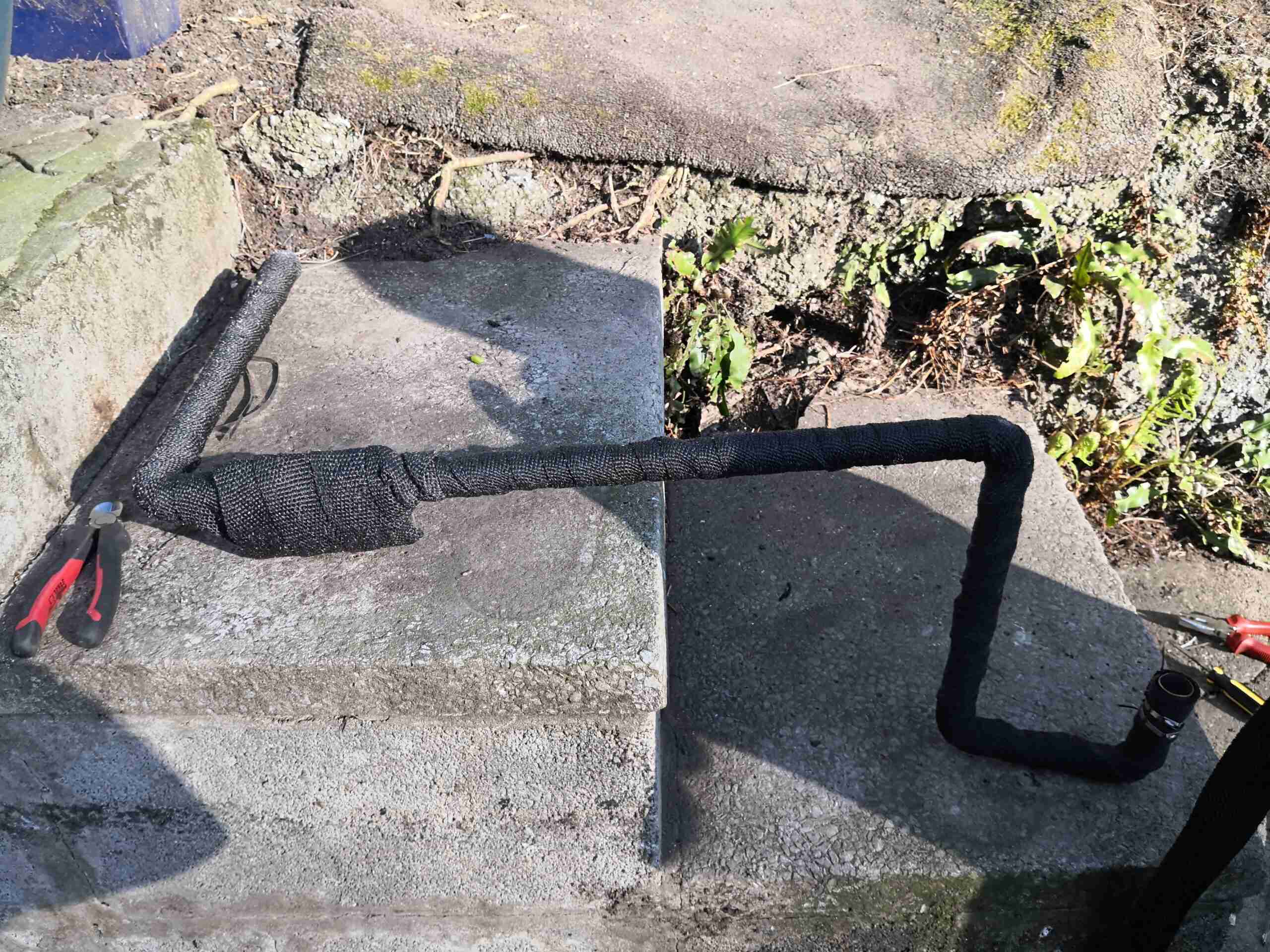
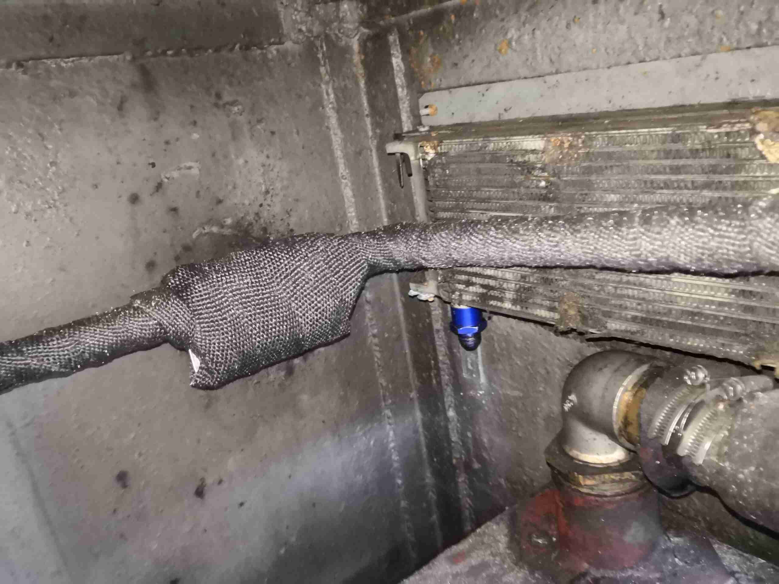
Fibreglass Wrap
To keep the heat away from sensitive parts in the engine bay, the entire assembly has been wrapped in fibreglass insulation tape, and secured with stainless steel ties. It’s important to use only stainless in these applications – the fibreglass wrap will hold any moisture in contact with all the parts, and mild steel will rapidly convert back into Iron Oxide 😉
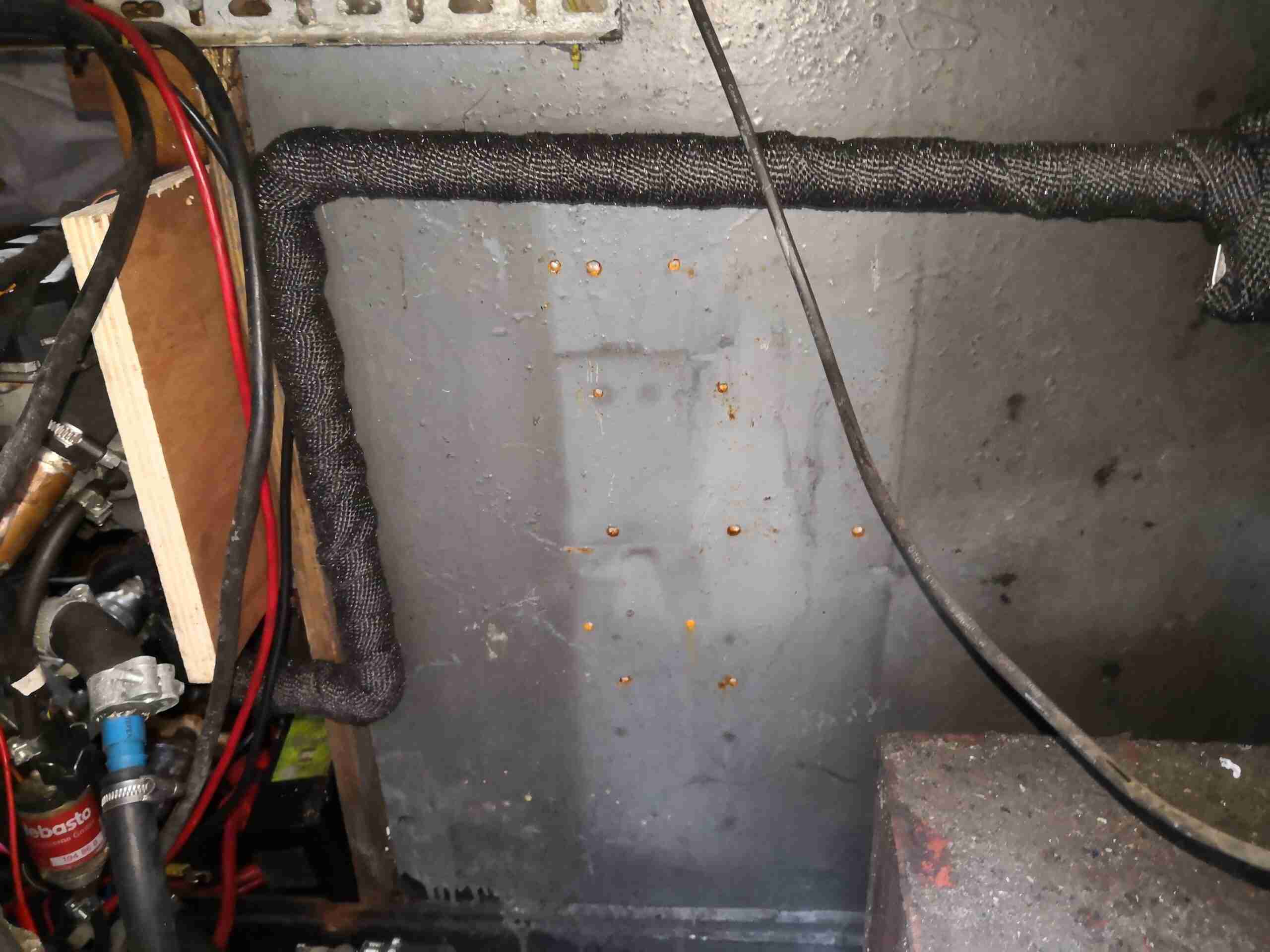
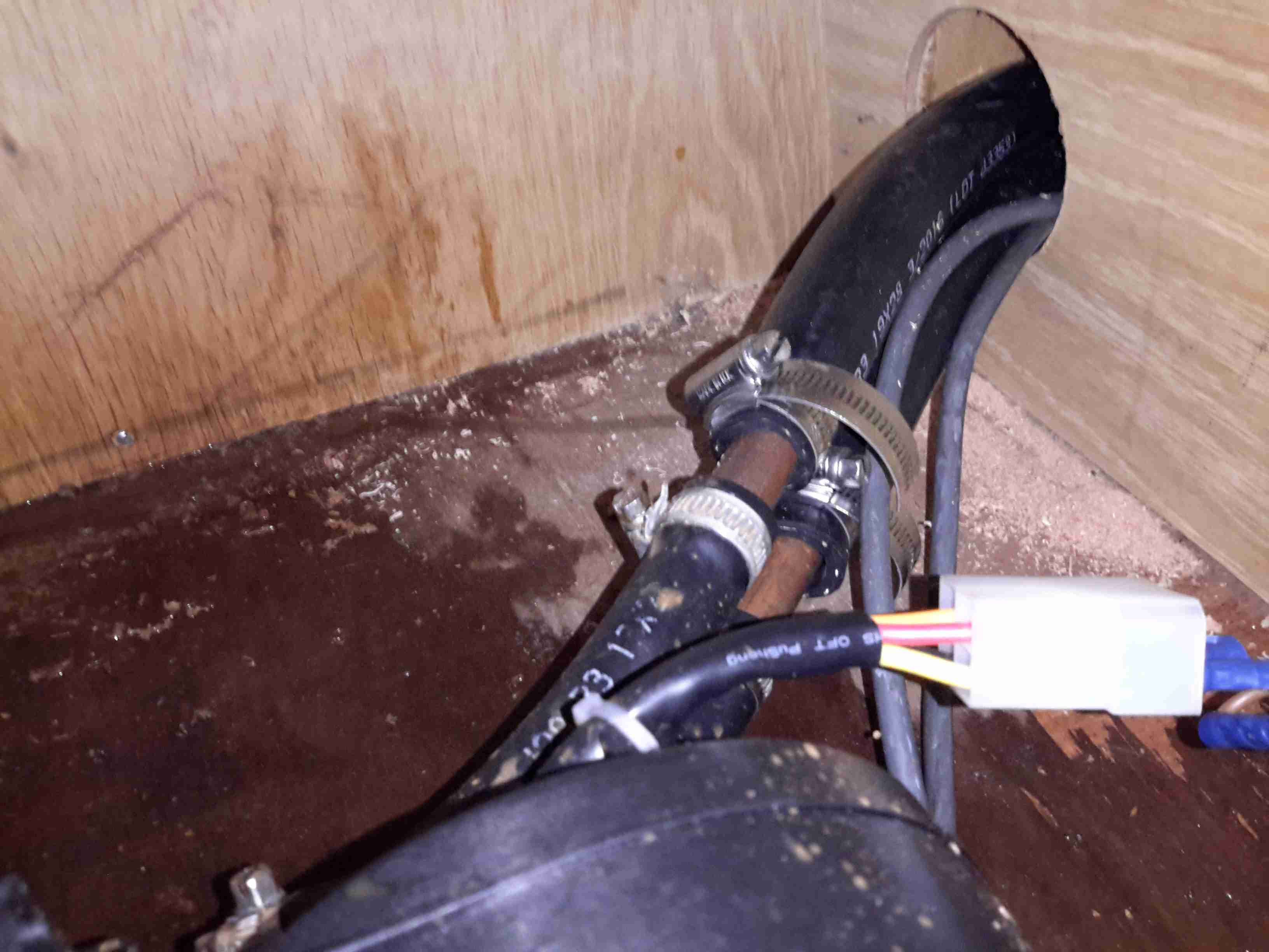
Heater End
The heater itself is on the other side of the plywood board in the photo, the cooling water pipework can be seen on the lower left, along with the diesel dosing pump. The main fuel tank is just visible in the bottom right corner.
Skin Fitting Connection
The other end is sized for a snug fit onto the exhaust skin fitting, just astern of the old oil cooler. This is set to be removed at some stage, and be replaced with an engine bay blower for ventilation.
Silencer
In the corner, next to the bulkhead sits the silencer.
In all, this setup also made the heater quieter, probably due to the longer length of exhaust pipework, which is now about 1.5 metres from the heater outlet to the skin fitting. This is a bonus – the exhaust of these heaters without any silencing sounds like a jet engine!
It recently became rather obvious there was something amiss with the water heater on board nb Tanya Louise – lots of smoke from the exhaust, failed starts, and finally a total refusal to start altogether.
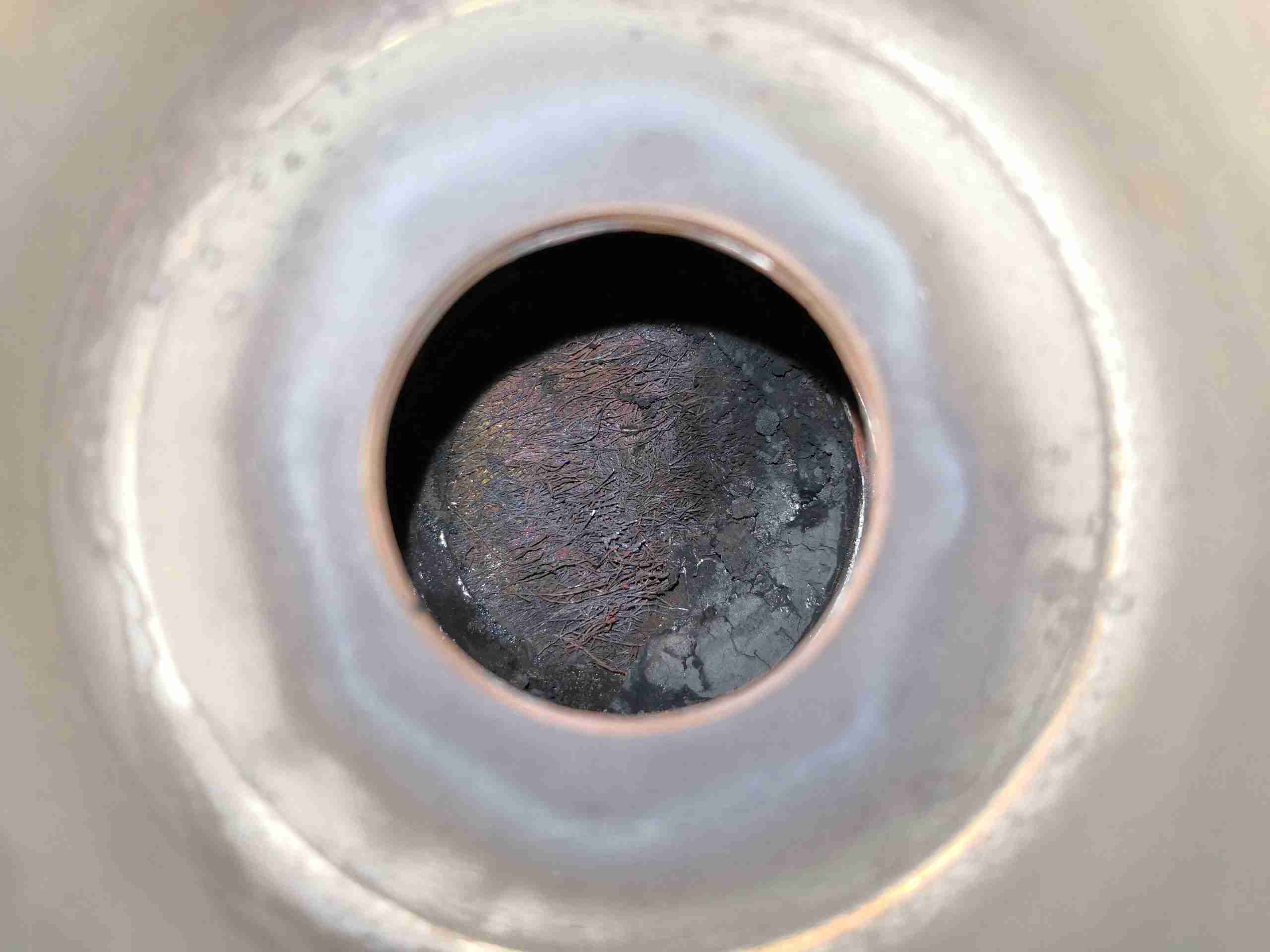
Combustion Chamber
On disassembly, it was clear the burner was the issue – above. The mesh at the back where the fuel inlet enters the burner is completely knackered. The burner in these heaters, like the Eberspachers, is evaporative. Diesel fuel is led into a high-surface area mesh tube, or pad in this case, where it is vaporized to be burned with air from the combustion blower. Initially, this heat is provided by the glow plug, but after the unit has fired, the heat of combustion keeps the process going.
Burner Deposits 1
As can be seen at left, there’s quite the build-up of solid carbon around the burner, blocking most of the mesh & the air mixing holes in the tube. This was also after I’d removed most of the fouling!
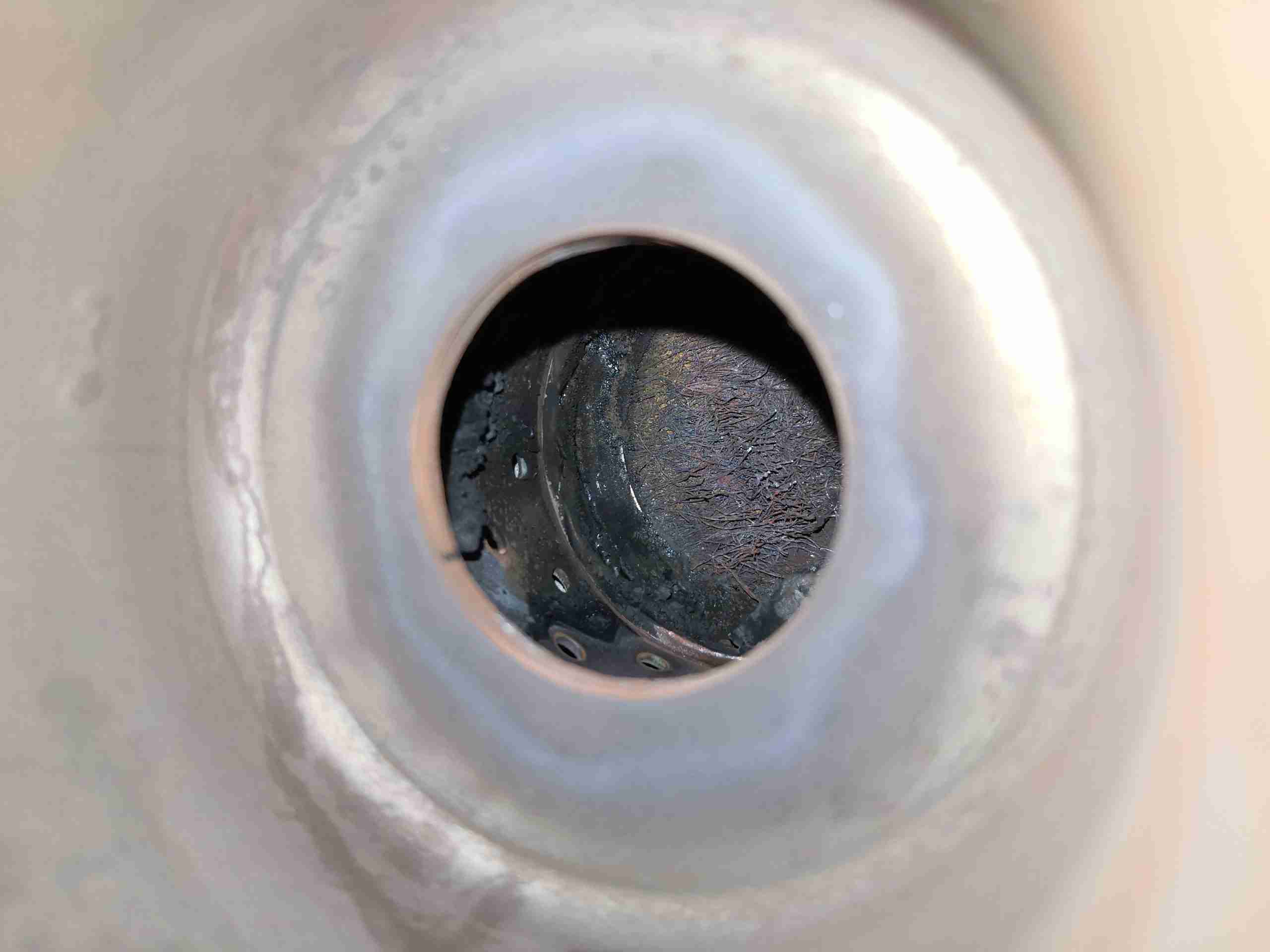
Burner Deposits 2
More deposits are seen on the other side, along with some of the air mixing holes.
Inlet Plate
Now, the problem is that these burner units are not meant to be refurbished. These units are considered by the manufacturer to be disposable, and are welded together as a result. There’s another issue – I don’t believe that a component costing around £295 in a service kit as DISPOSABLE. There’s nothing wrong with the structure of the burner at all – it’s Stainless Steel, and is in good shape with no heat damage. The only fault is with the mesh being burned out from long use. Luckily, replacement burner meshes are available on eBay from Chinese suppliers, so on with the repair! One of the welds that needs to be removed can be seen here next to the glow plug well, and there are 3 spots around the rim that are welded in this way. Delicate use of a grinding wheel on the welds allows this to be removed intact.
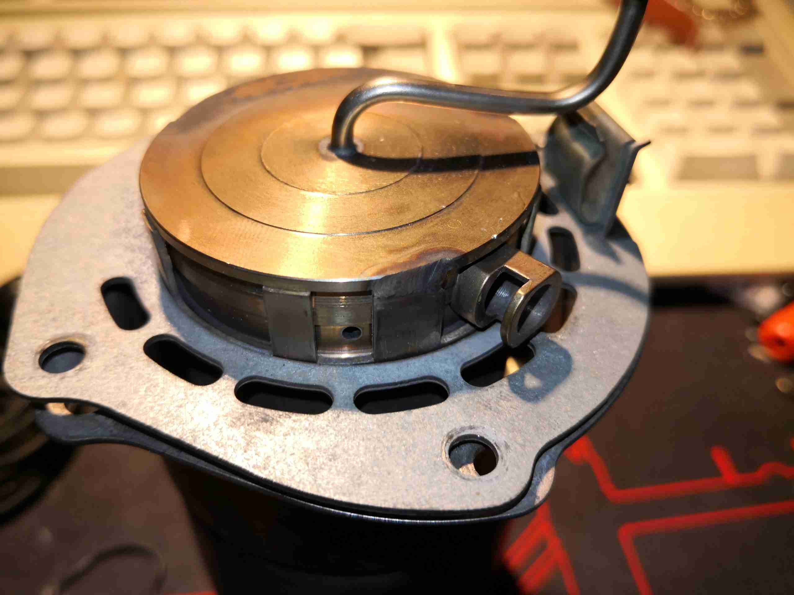
Burner Tube
Once the welds have been ground off, the fuel inlet plate with the mesh can be pulled from the back of the burner. It’s a good idea to add some registration marks to both pieces before they’re separated, so they can be put back together in the same orientation – required for both the glow plug wiring, and the fuel inlet tube to line up with the hole in the heater housing. The ring of slots visible around the edge of the tube are the combustion air inlets, and the air is directed through a ring of holes in the combustion chamber, quite similar to a turbine engine combustor.
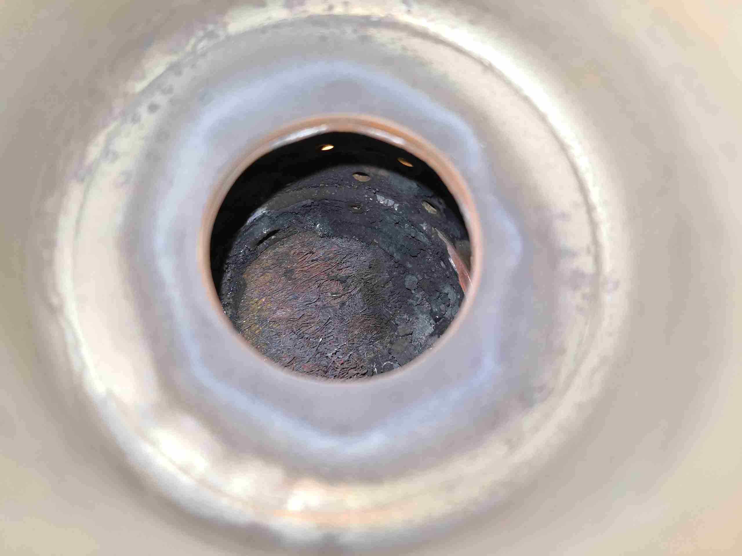
Old Burner Mesh
Now I’ve got the back of the burner removed, the clogging is much easier to see. The mesh itself has clearly been subject to very high heat, and is partially burned away, along with most of the surface being clogged up with coal from incomplete combustion. It’s difficult to see here, but the mesh pad is held in place with a large circlip around the edge, all will become clear after cleaning. All the hard carbon needs to be scraped out of the cup, clearing the way for the clip to be pried out of it’s groove.
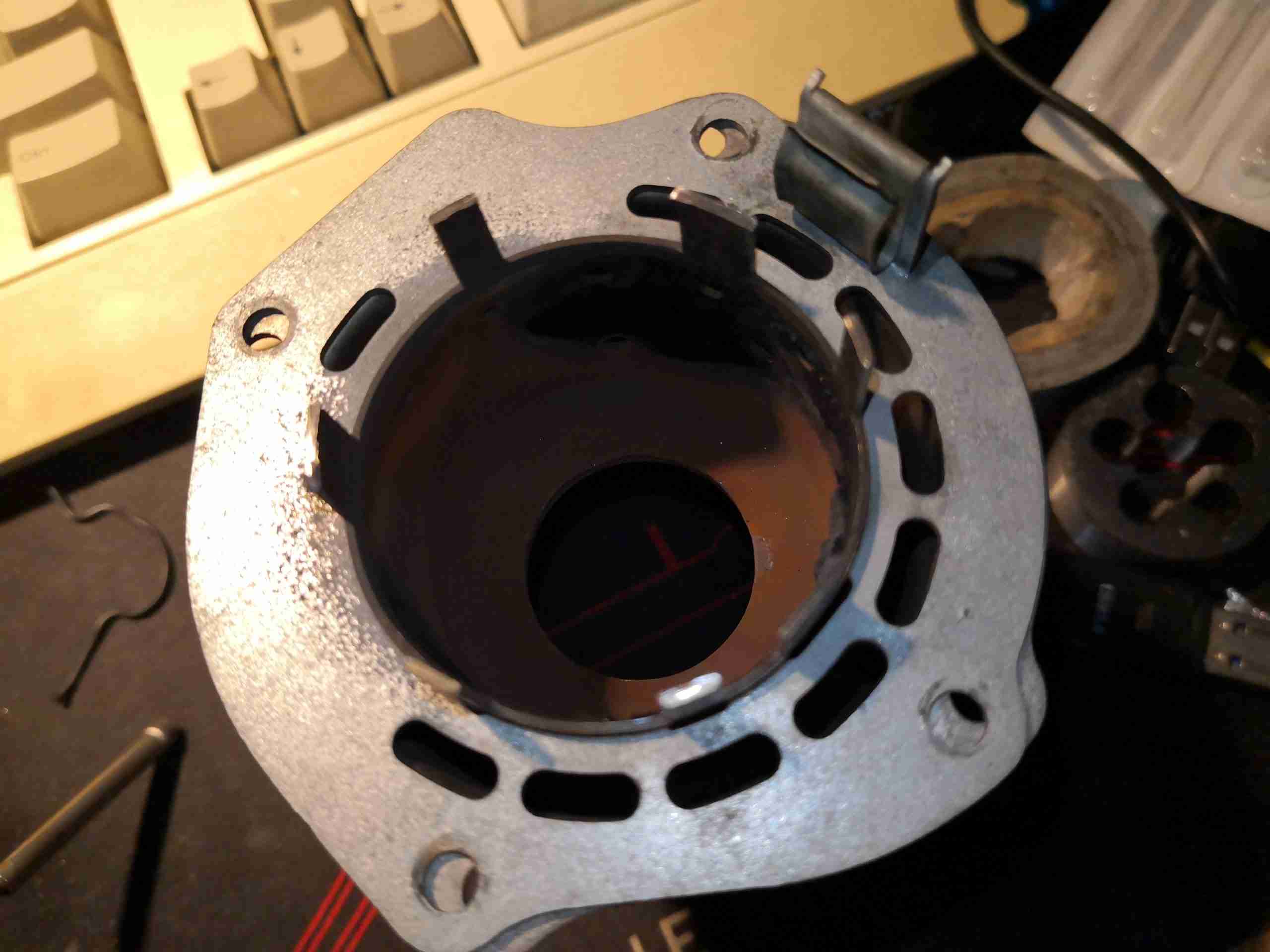
Cleaned Cup
After a lot of scraping with the sharp end of a small screwdriver, the cup has been relieved of enough carbon to be recognisable again! The fuel inlet tube is in the centre of the backplate, with the circlip groove around the edge. Crimp marks are visible on the top edge of the groove – I think Webasto actually crimps the ring in place after fitting, which does make removal a bit more tricky, but I did manage to get it out intact, even if heat has removed most of the heat treat from the steel – making it soft. Be careful here!
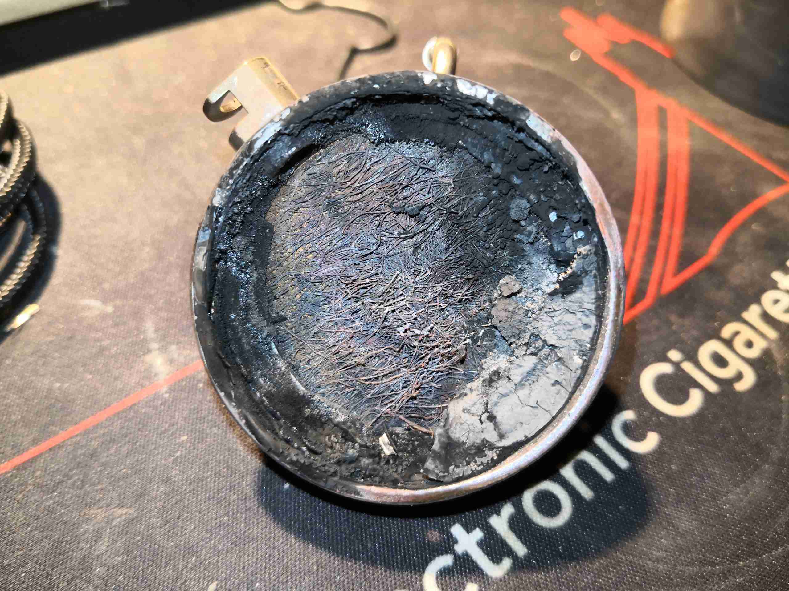
New Mesh Fitted
Fitting the new mesh is pretty simple. These have a sharp pressed side & a convex side, the convex side must face outwards from the cup. The circlip is visible around the edge of the mesh, with the ends next to the glow plug well. Make sure that the clip is equally spaced around the glow plug to make sure it doesn’t foul the plug when that’s replaced.
Now comes the issue of reattaching the cup to the back of the burner tube. I didn’t want to re-weld, since the assembly is Stainless Steel & I don’t have a TIG setup at present. I do have some stainless wire for the MIG, but this would also leave me with the issue of future disassembly if the mesh needs replacement again. Brazing is also not possible for the same reason – once brazed, it’s a permanent assembly.
Burner Reassembled
Since there are some tabs that were never welded, I decided to drill & tap M2.5 through these & use 304 stainless screws to hold the components together. This should allow removal in the future if required.
Well it was only a matter of time until we had a major failure of the onboard hydraulic system on board the boat, and this weekend proved to be that point in time.
Hose End
This is what remains of one of the main hoses to the propulsion motor, the fitting has been blown off the end of the hose! This occurred when I moved into reverse to stop the boat for oncoming traffic, and suddenly I lost all drive. The end result is a bilge filled with hydraulic oil, and zero power for manoeuvring.
The hose outer cover has been cut through by the fitting, like it had been sliced through with a knife, what remains of the inner liner & outer sheath is still in the fitting:
Fitting
Here’s the end of the offending fitting, with the remains of the hose. I suspect this termination wasn’t done correctly in the first place – either the swage was done too tight, cutting into the hose, or the fitting was never pushed all the way onto the hose before swaging, resulting in reduced strength.
Now comes the effort of cleaning out the roughly 40L of oil now in the bilges, refilling the oil tank & getting new hoses made up.
Here we have another piece of tech from Sterling Power – this is their Advanced Alternator Regulator, the Pro Reg D. Since I’m rejigging the alternator setup onboard, I figured I’d do a little teardown.
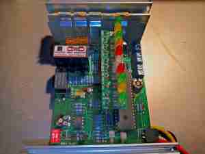
Cover Removed
Removing the top cover reveals the main PCB, which is slotted into the Aluminium heatsink extrusion. It’s a pretty well packed board, with both sides packed with tracks. There’s a small fan at the top of the unit, to keep the heatsink cool, but this has never worked for as long as this regulator has been in service.
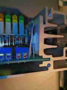
Thermistor
Here would be the reason the fan has never operated – the thermistor which is supposed to monitor the temperature of the heatsink the MOSFETs are clamped to isn’t even in contact with it. Simply glopped with heatsink compound & stuck behind the SIL pad. This is a little sloppy to say the least, and should be in close thermal contact with the heatsink. I’ll have to adjust this mounting.
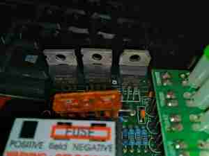
Field Control MOSFETs
Removing the heatsink shows the main field control FETs, both a P-Channel IRF4905 74A for positive field control, and a N-Channel IRF1010E 84A for negative field control. These are selected by moving the blade fuse between 3 spade terminals. Incedentally, Automotive-type blade fuses are not quick enough to protect semiconductors in the event of a serious fault, the likely result being an intact fuse & totally blown MOSFET. Nevermind.
Microcontroller
The unit is controlled by a Microchip PIC16F874, in a large package. There’s a couple of trimmers onboard for tweaking the calibration of the regulator, along with a dual DIP switch & a 12/24v link. Display is taken care of by a large row of indicator LEDs on a mezzanine board, there’s also a 4-pin Molex connector for a remote status display.
LED Board Mounting
The LED board is mounted to the main PCB with long pin headers, with no other support. Given the naturally vibrational nature of boats & their engines, having solder joints flapping about in the breeze isn’t a great plan, and fatigue is likely to set in here before long.
Loom Damage
Speaking of vibration, since the cable loom emerging from the aluminium case of the regulator is totally unprotected, the sharp edge of the extrusion has already begun chewing through the insulation! This has occurred after about 50 hours running time since the unit was installed. I’ll add a sleeve over the loom where it pops out of the corner to protect things better. Having the earthed aluminium casing munch it’s way through the insulation & short the entire loom out would not be a great result.
PCB Reverse
While I’ve got the board out of the casing, I’ve applied a heavy coat of PCB conformal coating to the back to help keep the moisture out, once everything is back together the top of the PCB will get the same treatment after masking off the parts that wouldn’t take kindly to a blasting with conformal coating.
The Sterling charger we’ve had on board nb Tanya Louise since Feb 2014 has bitten the dust, with 31220 hours on it’s internal clock. Since we’re a liveaboard boat, this charger has had a lot of use while we’re on the mooring during winter, when the solar bank isn’t outputting it’s full rate. First, a bit of a teardown to explore the unit, then onto the repair:
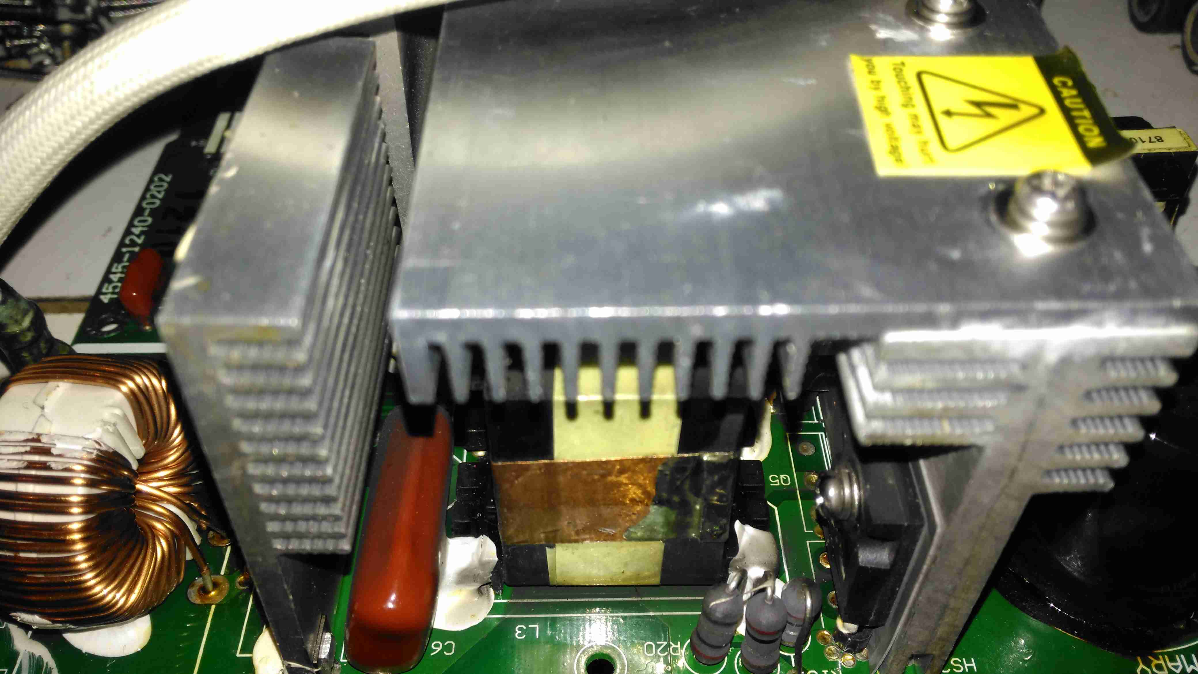
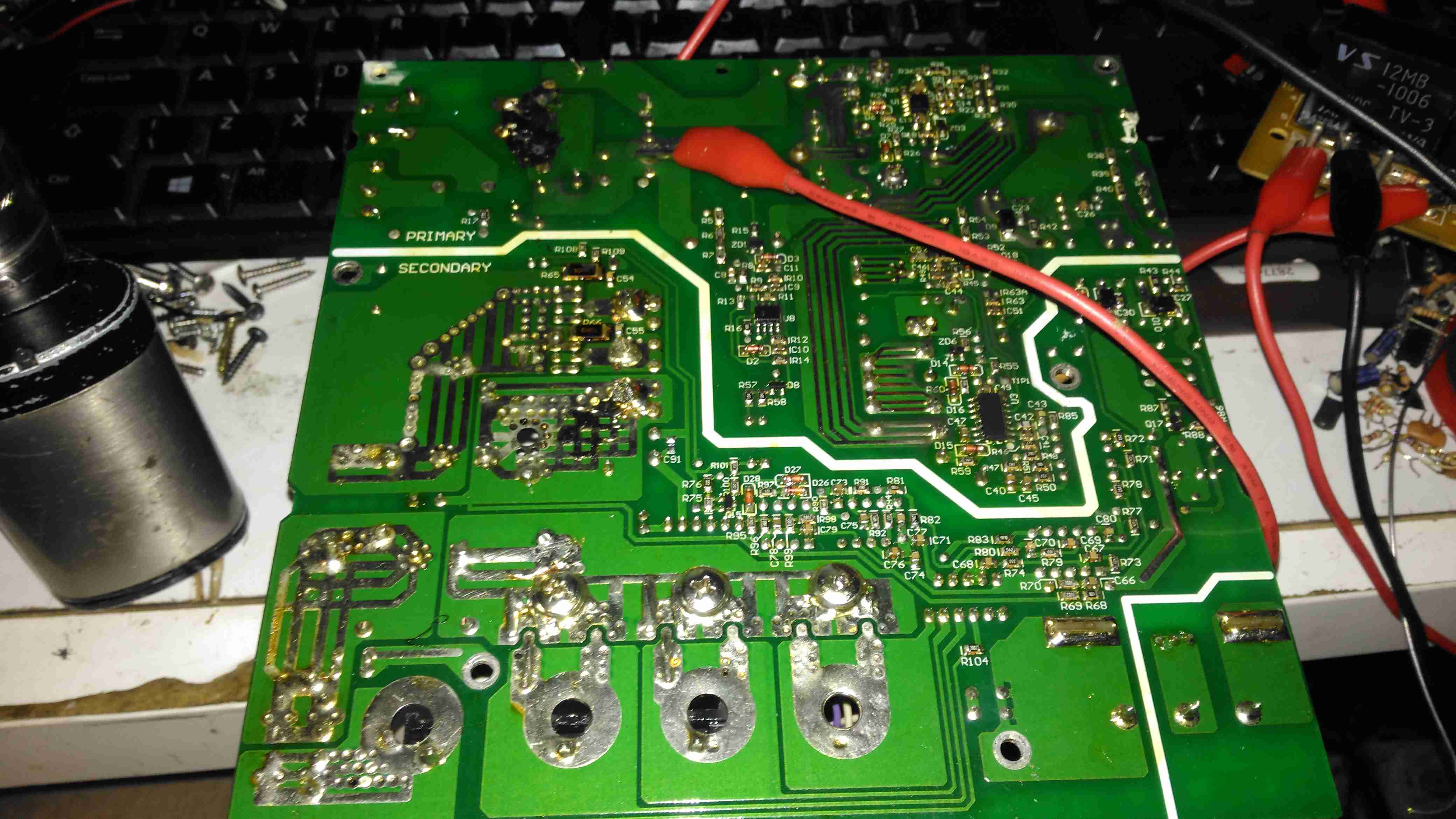
Active PFC Section
There’s the usual mains input filtering on the left, with the bridge rectifier on it’s heatsink.
Underneath the centre massive heatsinks is the main transformer (not visible here) & active PFC circuit. The device peeking out from underneath is the huge inductor needed for PFC. It’s associated switching MOSFET is to the right.
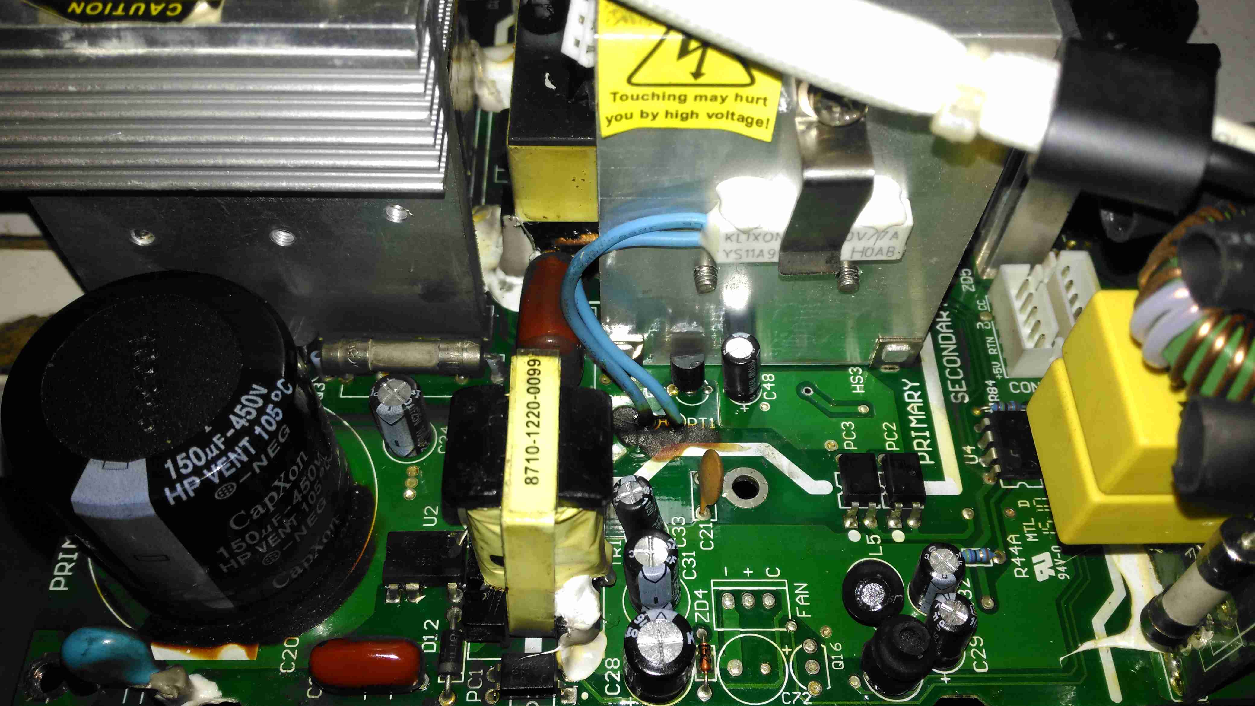
Logic PSU Section
On the other side of the PFC section is the main DC rail filter electrolytic, a 450v 150µF part. Here some evidence of long-term heating can be seen in the adhesive around the base, it’s nearly completely turned black! It’s not a decent brand either, a Chinese CapXon.
The PCB fuse just behind it is in the DC feed to the main switching supply, so the input fuse only protects the filter & Active PFC circuitry. Luckily this fuse didn’t blow during the failure, telling me the fault was earlier in the power chain.
The logic circuits are powered by an independent switching supply in the centre, providing a +5v rail to the microcontroller. The fan header & control components are not populated in this 10A model, but I may end up retrofitting a fan anyway as this unit has always run a little too warm. The entire board is heavily conformal coated on both sides, to help with water resistance associated with being in a marine environment. This has worked well, as there isn’t a single trace of moisture anywhere, only dust from years of use.
There is some thermal protection for the main SMPS switching MOSFETS with the Klixon thermal fuse clipped to the heatsink.
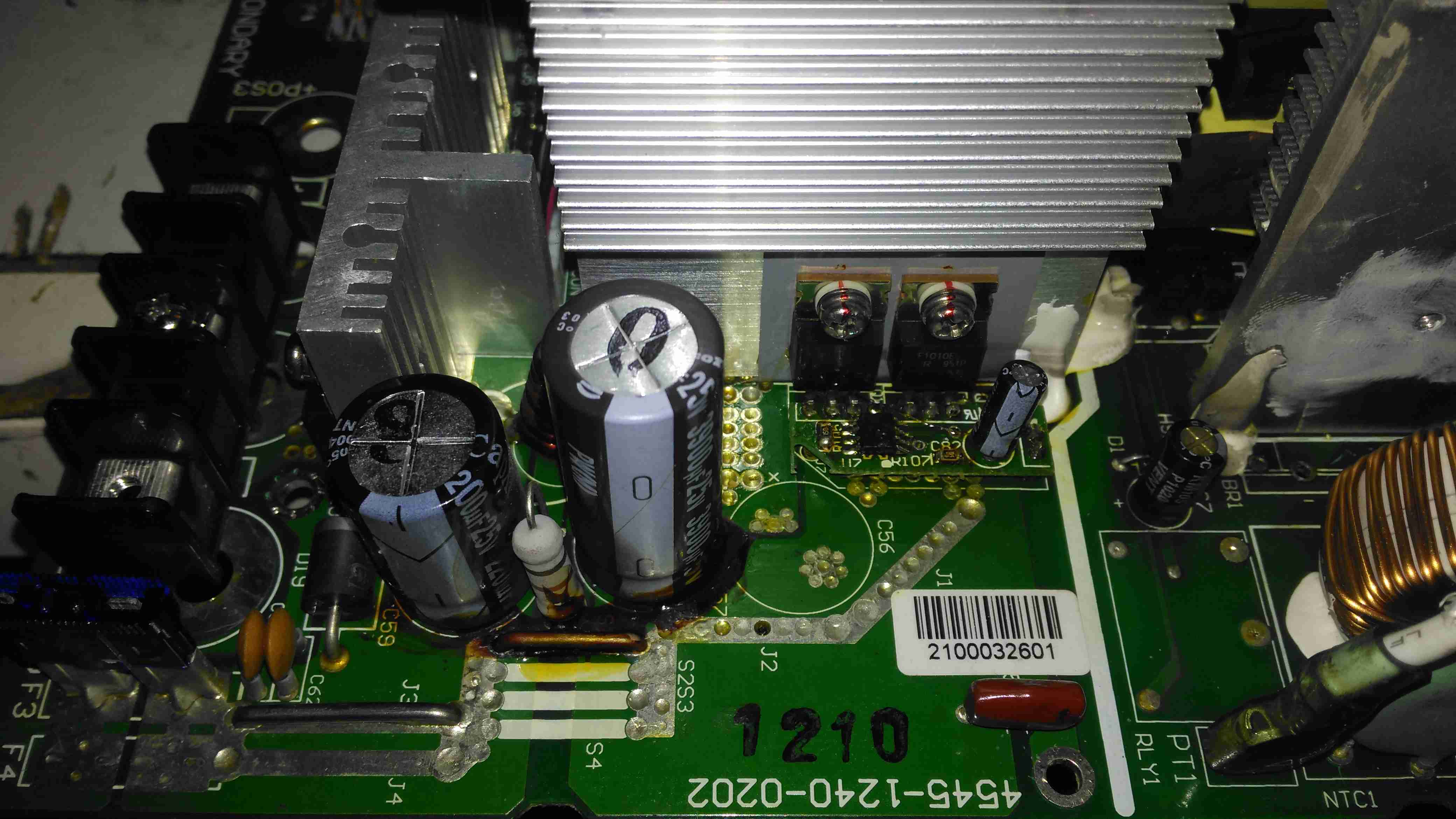
DC Output Section
The DC output rectifiers are on the large heatsink in the centre, with a small bodge board fitted. Due to the heavy conformal coating on the board I can’t get the ID from this small 8-pin IC, but from the fact that the output rectifiers are in fact IRF1010E MOSFETS, rated at 84A a piece, this is an synchronous rectifier controller.
Oddly, the output filter electrolytics are a mix of Nichicon (nice), and CapXon (shite). A bit of penny pinching here, which if a little naff since these chargers are anything but cheap. (£244.80 at the time of writing).
Hiding just behind the electrolytics is a large choke, and a reverse-polarity protection diode, which is wired crowbar-style. Reversing the polarity here will blow the 15A DC bus fuse instantly, and may destroy this diode if it doesn’t blow quick enough.
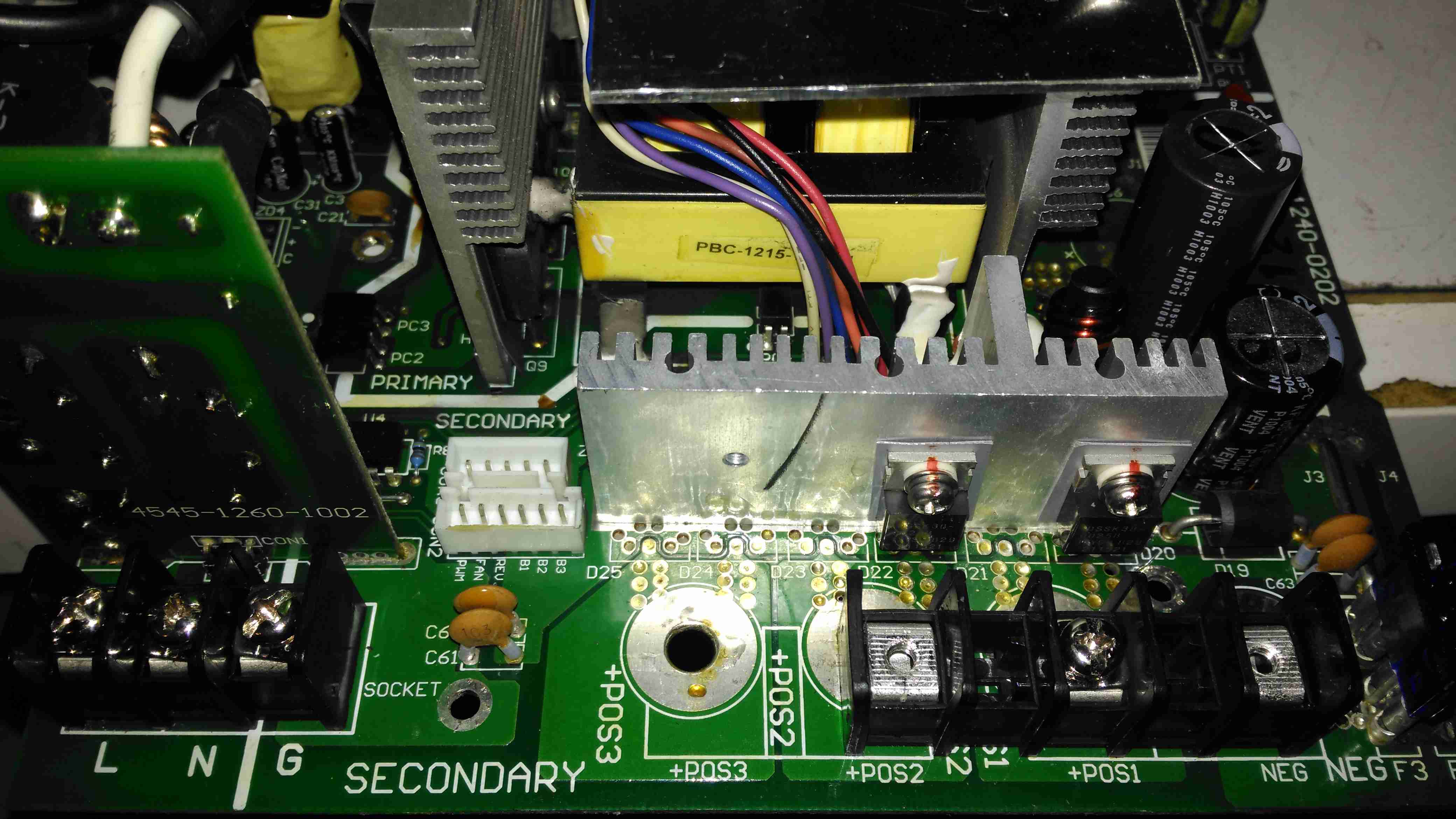
DC Outputs
Right on the output end are a pair of large Ixys DSSK38 TO220 Dual 20A dual Schottky diodes, isolating the two outputs from each other, a nice margin on these for a 10A charger, since the diodes are paralleled each channel is capable of 40A. This prevents one bank discharging into another & allows the charger logic to monitor the voltages individually. The only issue here is the 400mV drop of these diodes introduce a little bit of inefficiency. To increase current capacity of the PCB, the aluminium heatsink is being used as the main positive busbar. From the sizing of the power components here, I would think that the same PCB & component load is used for all the chargers up to 40A, since both the PFC inductor & main power transformer are massive for a 10A output. There are unpopulated output components on this low-end model, to reduce the cost since they aren’t needed.
Front Panel Control Connections
A trio of headers connect all the control & sense signals to the front panel PCB, which contains all the control logic. This unit is sensing all output voltages, output current & PSU rail voltages.
Front Panel LEDs
The front panel is stuffed with LEDs & 7-segment displays to show the current mode, charging voltage & current. There’s 2 tactile switches for adjustments.
Front Panel Reverse
The reverse of the board has the main microcontroller – again identifying this is impossible due to the heavy conformal coat. The LEDs are being driven through a 74HC245D CMOS Octal Bus Transceiver.
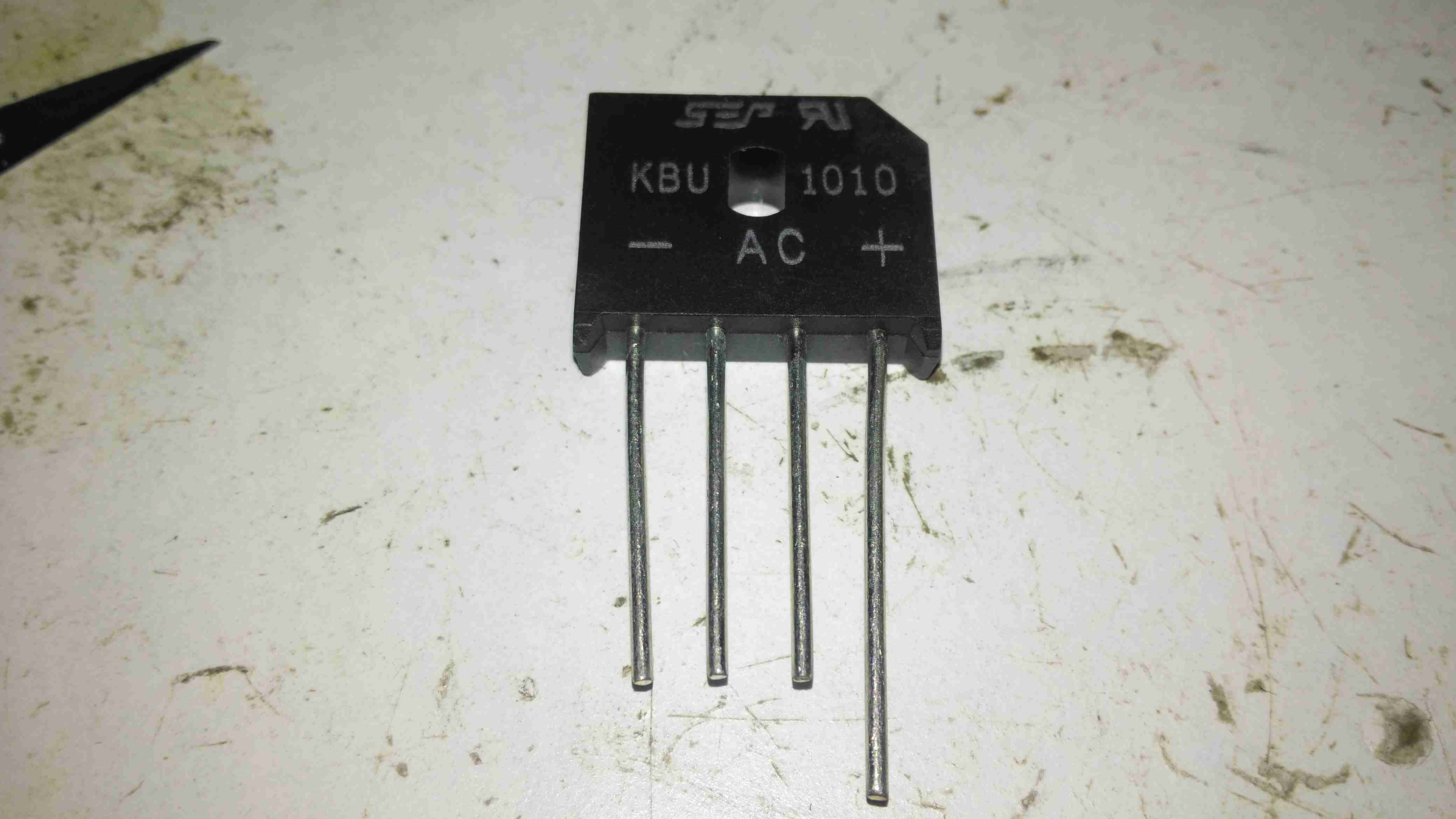
Now on to the repair! I’m not particularly impressed with only getting 4 years from this unit, they are very expensive as already mentioned, so I would expect a longer lifespan. The input fuse had blown in this case, leaving me with a totally dead charger. A quick multimeter test on the input stage of the unit showed a dead short – the main AC input bridge rectifier has gone short circuit.
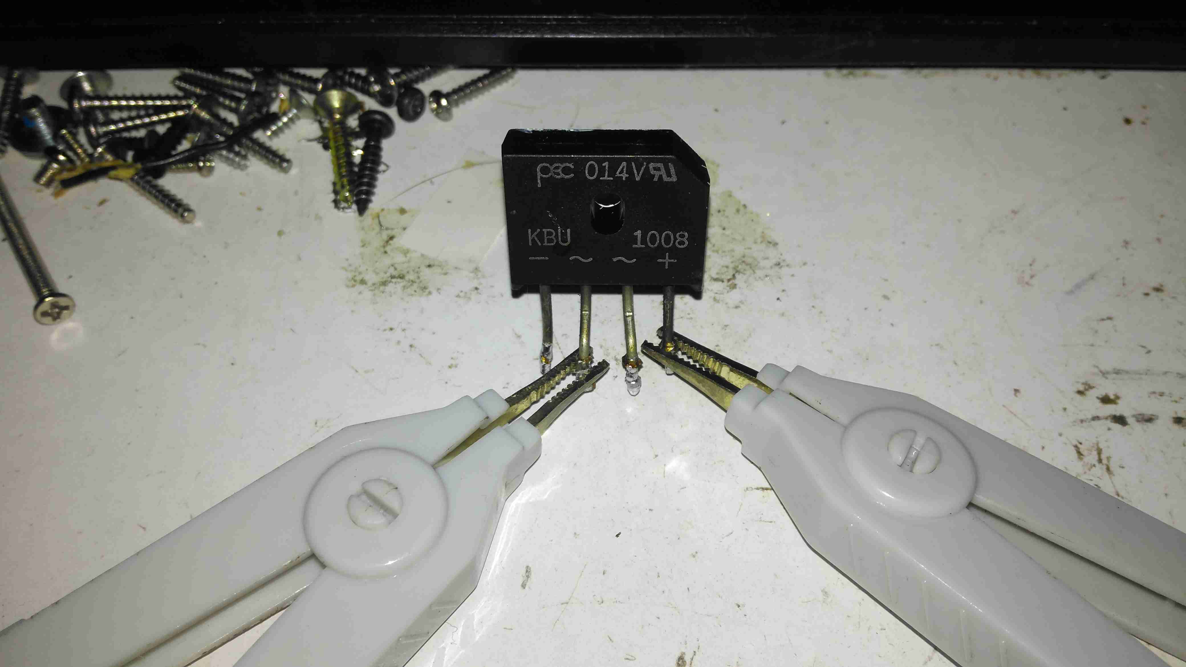
Bridge Rectifier Removed
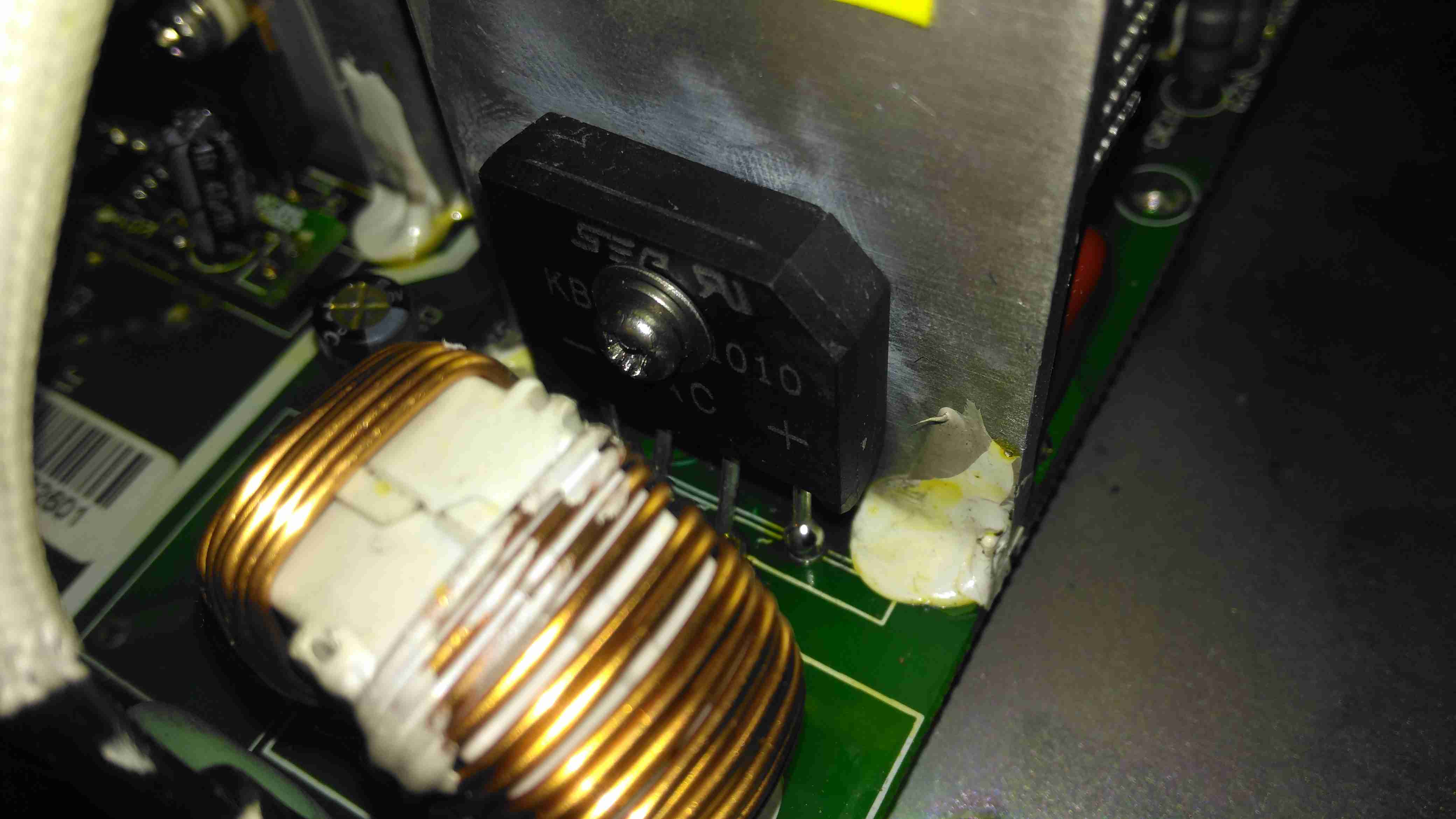
Here the defective bridge has been desoldered from the board. It’s a KBU1008 10A 800v part. Once this was removed I confirmed there was no longer an input short, on either the AC side or the DC output side to the PFC circuit.
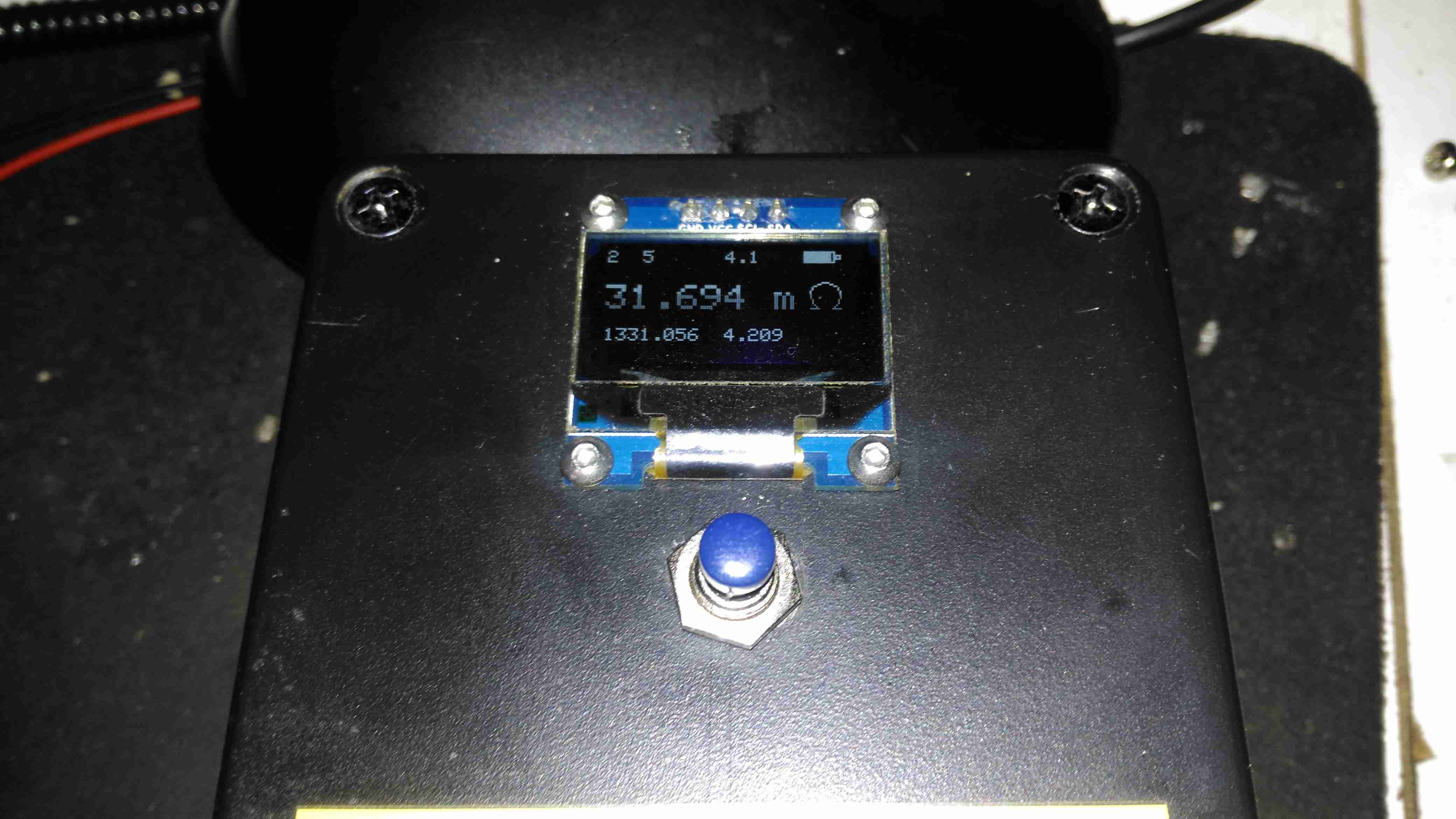
Testing The Rectifier
Time to stick the desoldered bridge on the milliohm meter & see how badly it has failed.
Yep, Definitely Shorted
I’d say 31mΩ would qualify as a short. It’s no wonder the 4A input fuse blew instantly. There is no sign of excessive heat around the rectifier, so I’m not sure why this would have failed, it’s certainly over-rated for the 10A charger.
Testing Without Rectifier
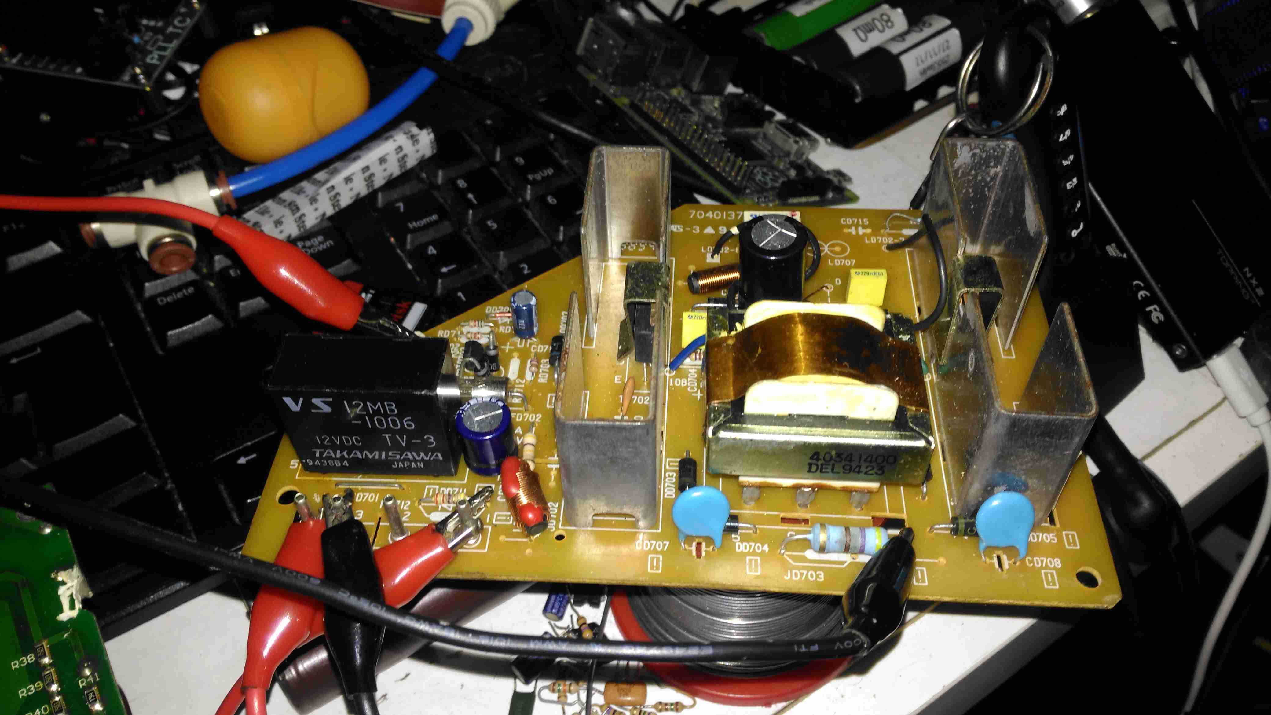
Now the defective diode bridge has been removed from the circuit, it’s time to apply some controlled power to see if anything else has failed. For this I used a module from one of my previous teardowns – the inverter from a portable TV.
Test Inverter
This neat little unit outputs 330v DC at a few dozen watts, plenty enough to power up the charger with a small load for testing purposes. The charger does pull the voltage of this converter down significantly, to about 100v, but it still provides just enough to get things going.
It’s Alive!
After applying some direct DC power to the input, it’s ALIVE! Certainly makes a change from the usual SMPS failures I come across, where a single component causes a chain reaction that writes off everything.
Replacement Rectifier
Unfortunately I couldn’t find the exact same rectifier to replace the shorted one, so I had to go for the KBU1010, which is rated for 1000v instead of 800v, but the Vf rating (Forward Voltage), is the same, so it won’t dissipate any more power.
Soldered In
Here’s the new rectifier soldered into place on the PCB & bolted to it’s heatsink, with some decent thermal compound in between.
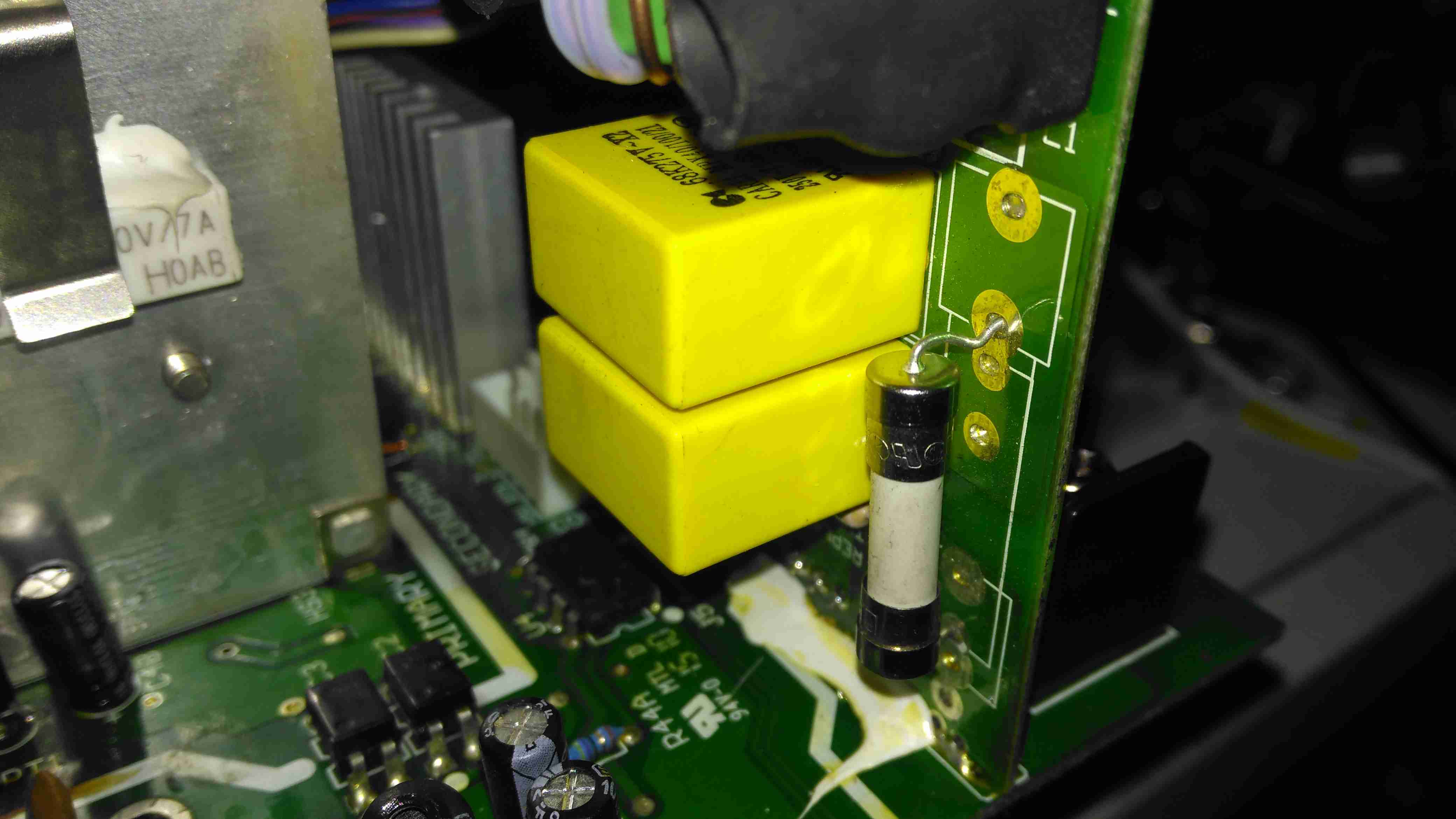
Input Board
Here is the factory fuse, a soldered in device. I’ll be replacing this with standard clips for 20x5mm fuses to make replacement in the future easier, the required hole pattern in the PCB is already present. Most of the mains input filtering is also on this little daughterboard.
Fuse Replaced
Now the fuse has been replaced with a standard one, which is much more easily replaceable. This fuse shouldn’t blow however, unless another fault develops.
Full Load Test
Now everything is back together, a full load test charging a 200Ah 12v battery for a few hours will tell me if the fix is good. This charger won’t be going back into service onboard the boat, it’s being replaced anyway with a new 50A charger, to better suit the larger loads we have now. It won’t be a Sterling though, as they are far too expensive. I’ll report back if anything fails!
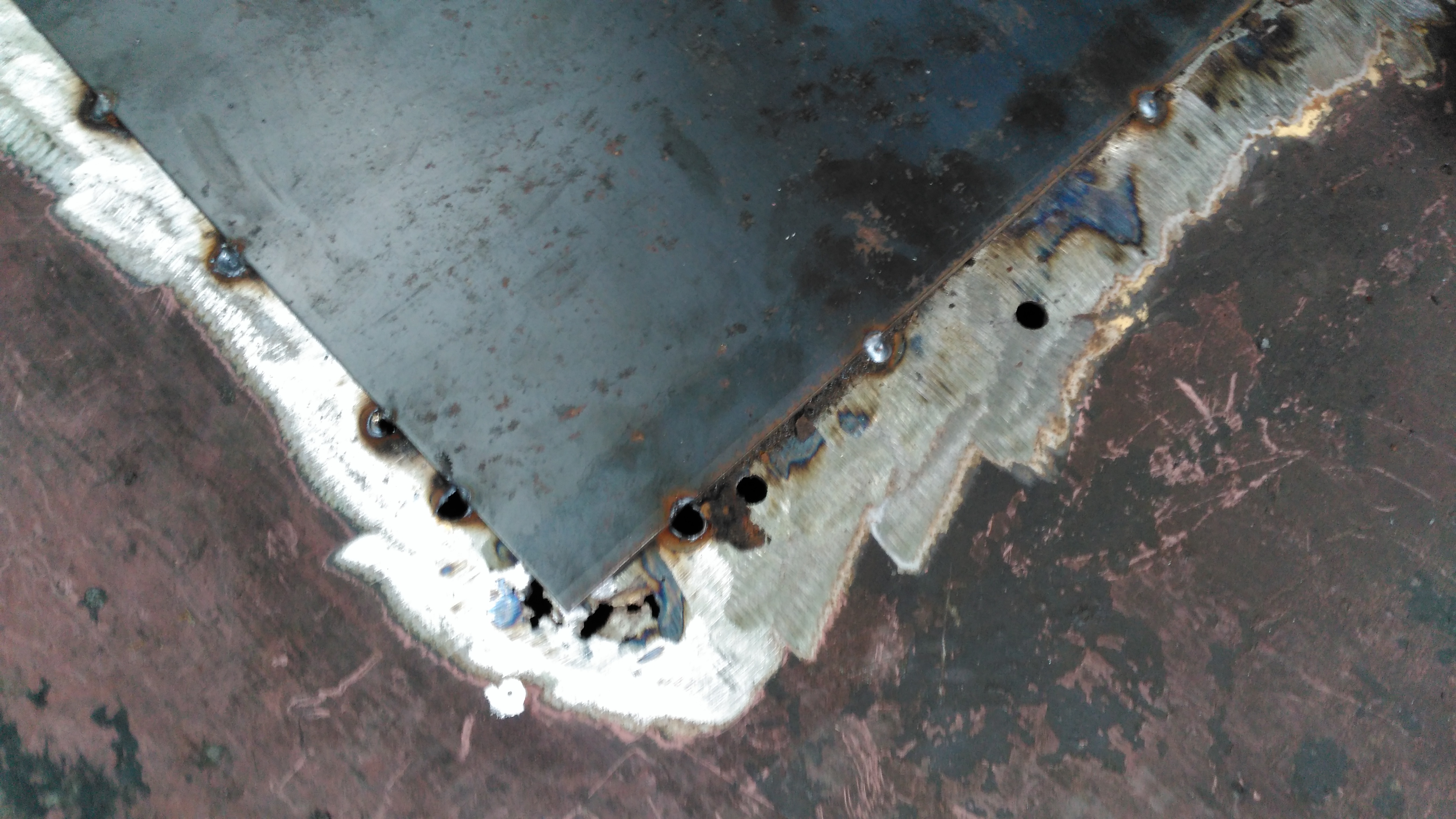
This is a part of the boat that hasn’t really had much TLC since we moved aboard, and finally it’s completely succumbed to corrosion, opening a rusty hole into the engine space below. I’ve already used a grinder to remove the rest of the locker – and even this had corroded to the point of failure all around the bottom just above the welds. The bulkhead forming the rear of the locker has also corroded fairly severely, so this will be getting cut out & replaced with a new piece of steel.
This was originally a 1/8″ plate, but now it’s as thin as foil in some places, with just the paint hiding the holes.
Replacement Steel
I’ve cut out as much of the corroded deck plate as possible – it’s supported underneath by many struts made of angle iron, and got the new 3mm replacement tacked in place with the MIG. I’ve not yet cut out the rotten section on the bulkhead, this will come after we’ve got the steel cut to replace it, as electrical distribution is behind this plate – I’d rather not have weather exposure to the electrical systems for long! Unfortunately more corrosion has showed itself around the edges of the old locker:
Thin Steel
Around the corner the steel has pretty much totally failed from corrosion coming from underneath – applying welding heat here has simply blown large holes in the steel as there’s nothing more than foil thickness to support anything.
Some more extensive deck replacement is going to happen to fix this issue, more to come when the steel comes in!
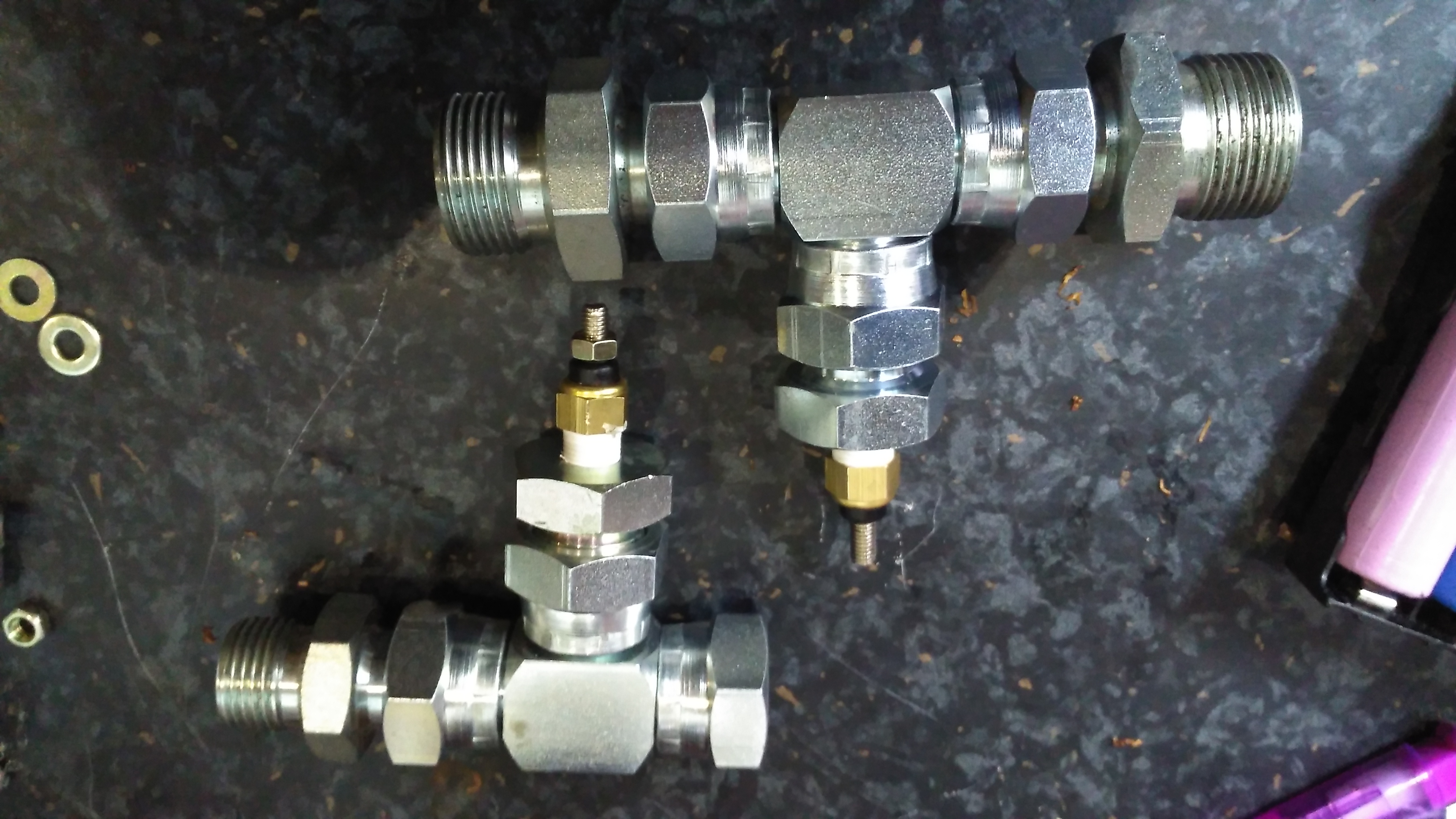
Since the engine & hydrostatic transmission were installed in the boat a few years back, the hydraulic oil cooler has been in the same fresh water circuit as the engine’s water cooling system, however this has been causing some heat issues with the engine & hydraulic system under a heavy load, such as when I’m using the onboard generator to run the welding gear. The hydraulic oil temp would rise to over 80°C during the course of a long day’s cruising – such temperatures will degrade the oil very quickly, and in turn will cause premature wear of the very expensive hydraulic pumps. (Not to mention increasing the requirement for hydraulic oil changes, which are very expensive). The engine oil has been cooled by a standard automotive oil radiator, with air forced over the matrix by two large fans. This is also pretty inefficient, so another cooler will be added to replace the automotive one.
This cooling requirement is caused by the inefficiency of hydraulic systems – a simple variable displacement piston pump driving a bent-axis piston motor has an overall efficiency of roughly 80%. Given our engine’s max power of 76HP (56.7kW), this gives an energy loss of 15.2HP (11.33kW) at maximum power. This extra heat overloaded the skin tank, resulting in a cooling system that didn’t really work all too well once the engine was hot.
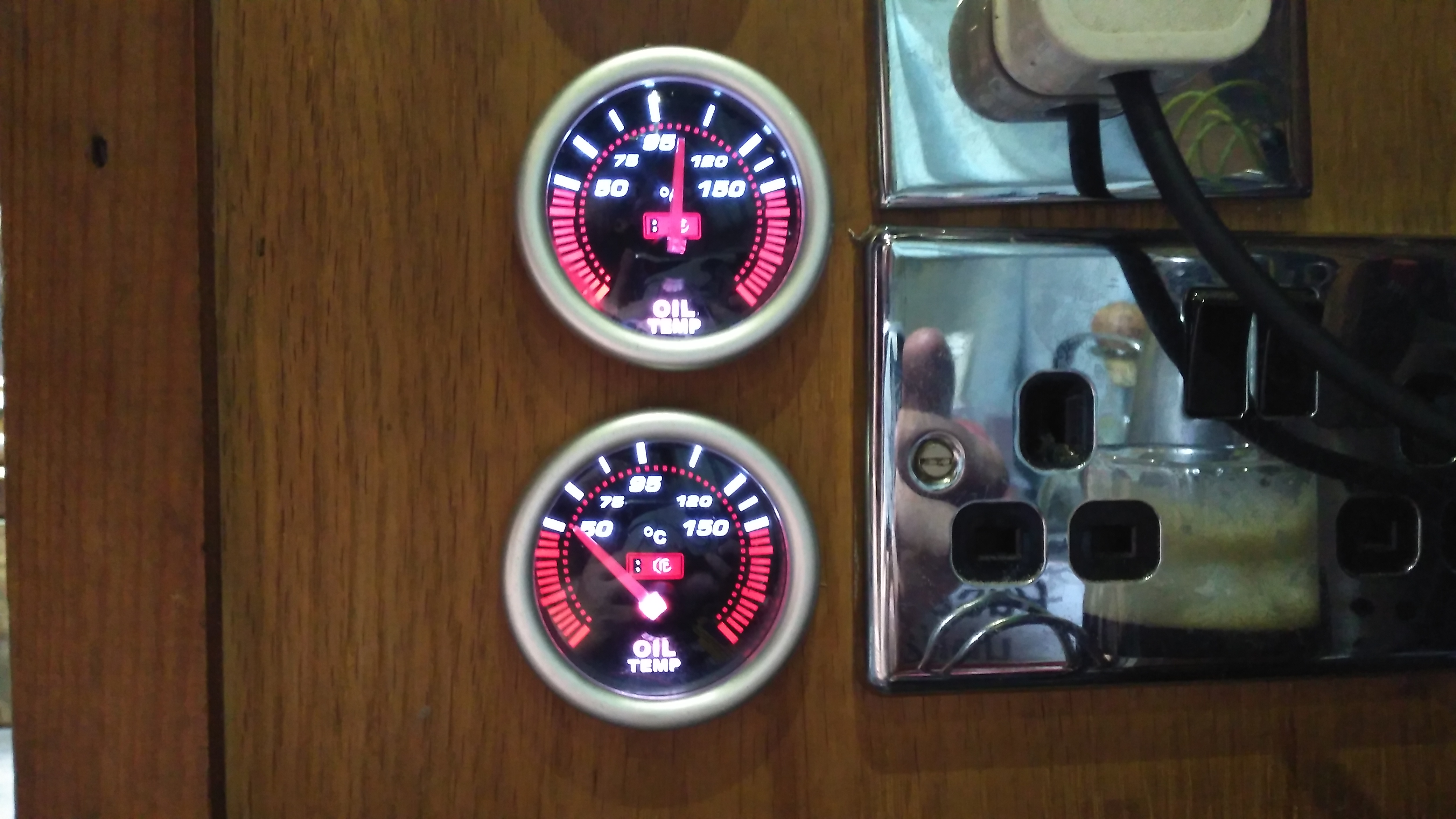
To solve this issue, we’ve decided to run a raw water circuit using the canal to remove the waste heat from the hydraulic system & engine oil, putting less of a heat load on the skin tank to bring the temperatures down to something reasonable. The image above show the system at running temperature after I installed the monitoring instruments. The top gauge is measuring engine oil temperature, at the point where it’s being fed to the bearings. The bottom one is measuring hydraulic oil temperature.
The engine oil temperature does have to be higher than any other cooling circuit on board, to boil off any condensate from the cylinders. Overcooling the oil in the sump will eventually cause sludging as the oil tries to absorb the resulting water. I’m aiming for a system temperature in the engine oil circuit of 95°C-120°C when the engine is under load & at operating temperature.
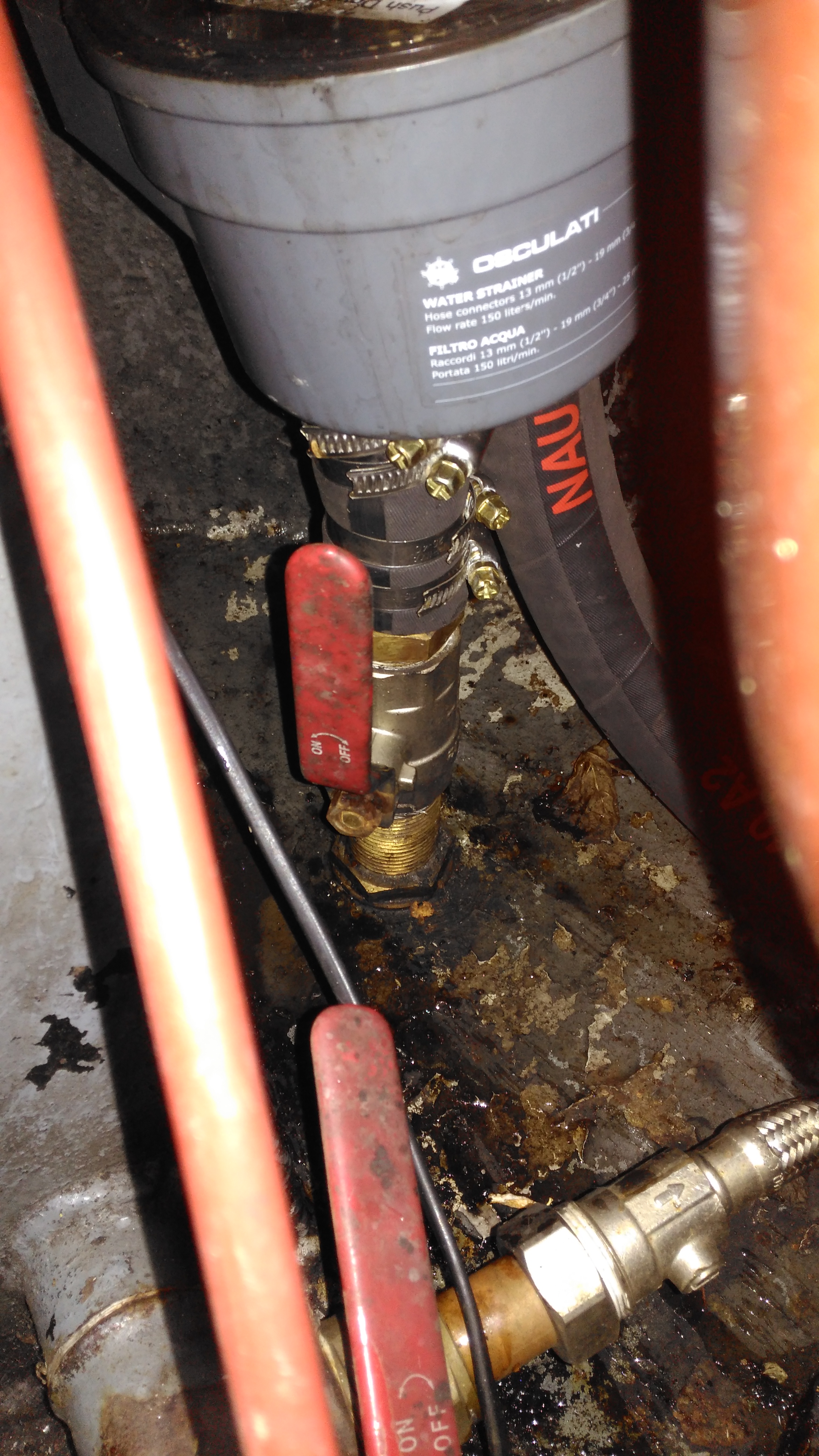
Raw Water Suction
Water from the canal is drawn from a skin fitting installed at the last drydock visit, pulling water through a strainer to remove all the large bits of muck. The large slotted screen on the suction skin fitting keeps larger objects out of the intake.
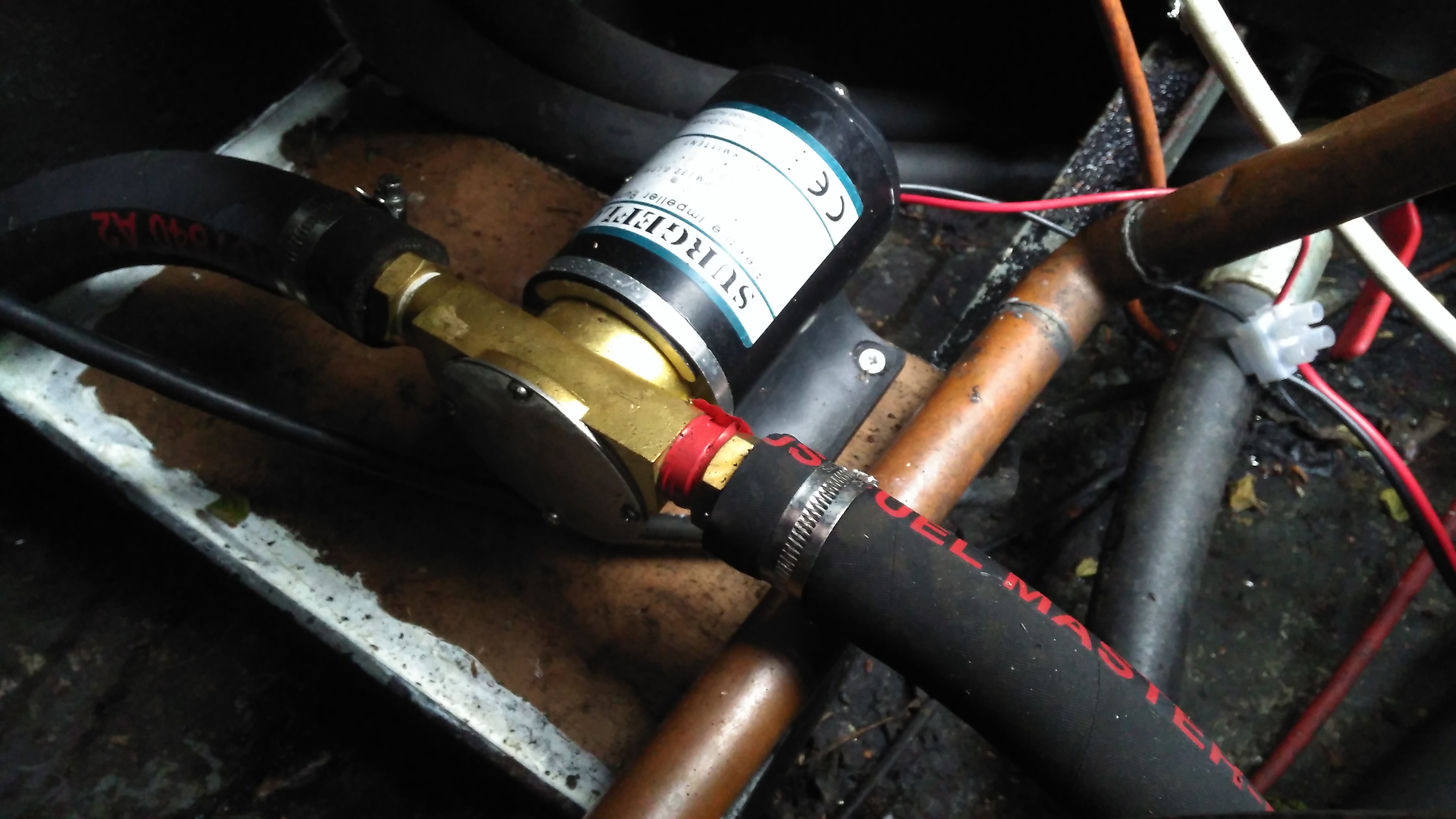
Raw Water Pump
A flexible impeller pump provides the power to move water through the system, in this case about 25L/Min. This pump is a cheap copy of a Jabsco pump from eBay. So far it’s been pretty reliable.
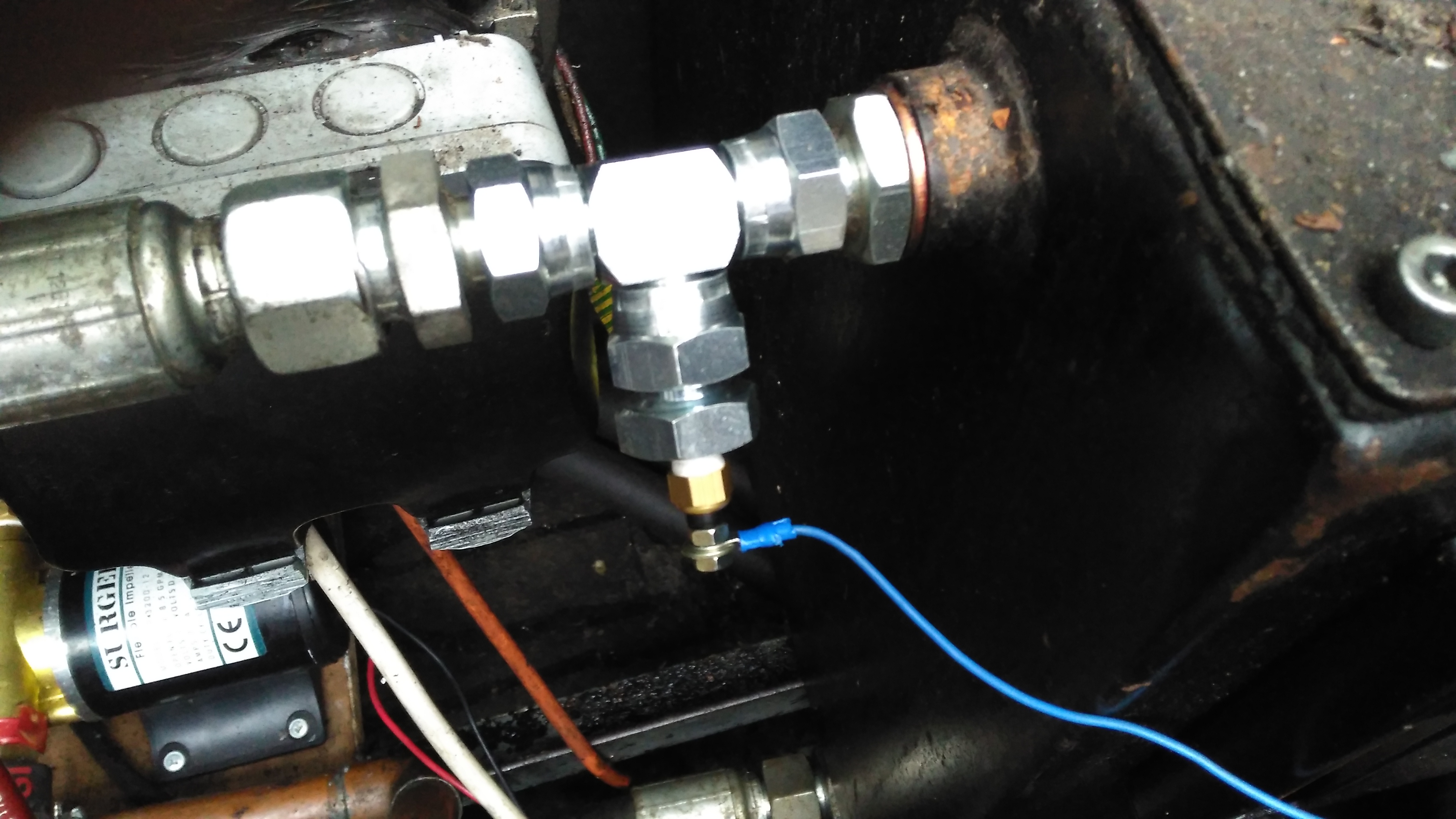
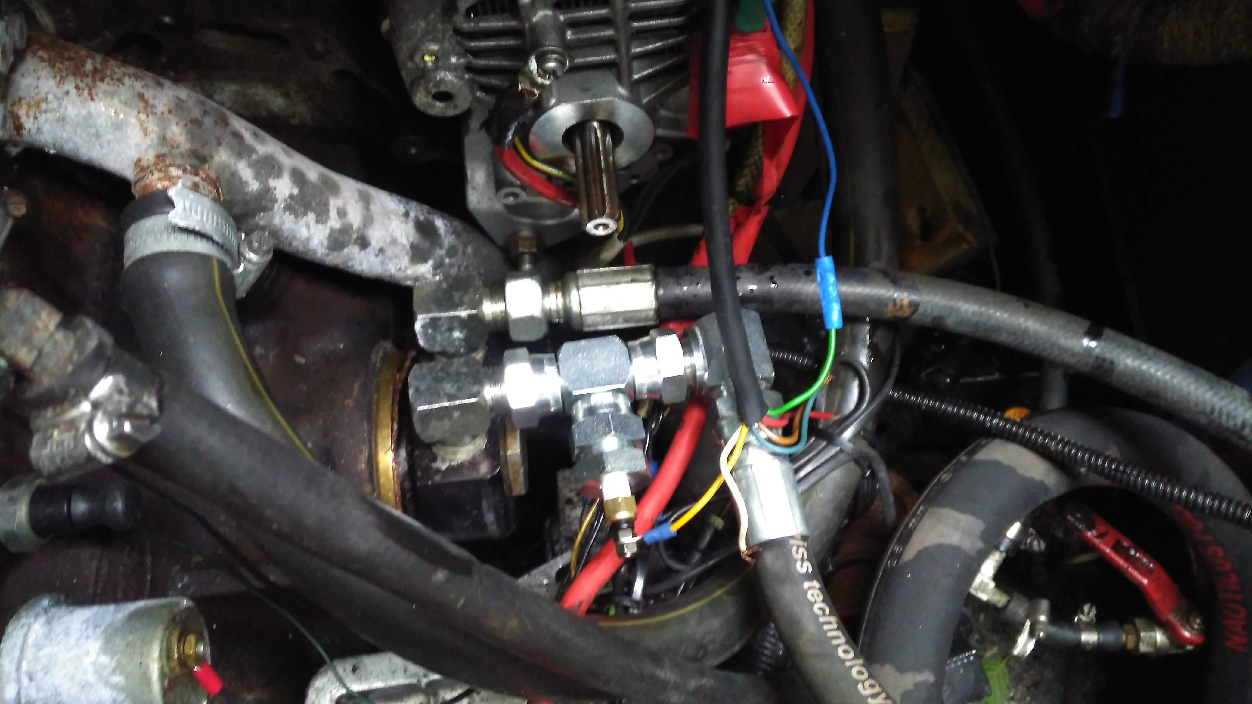
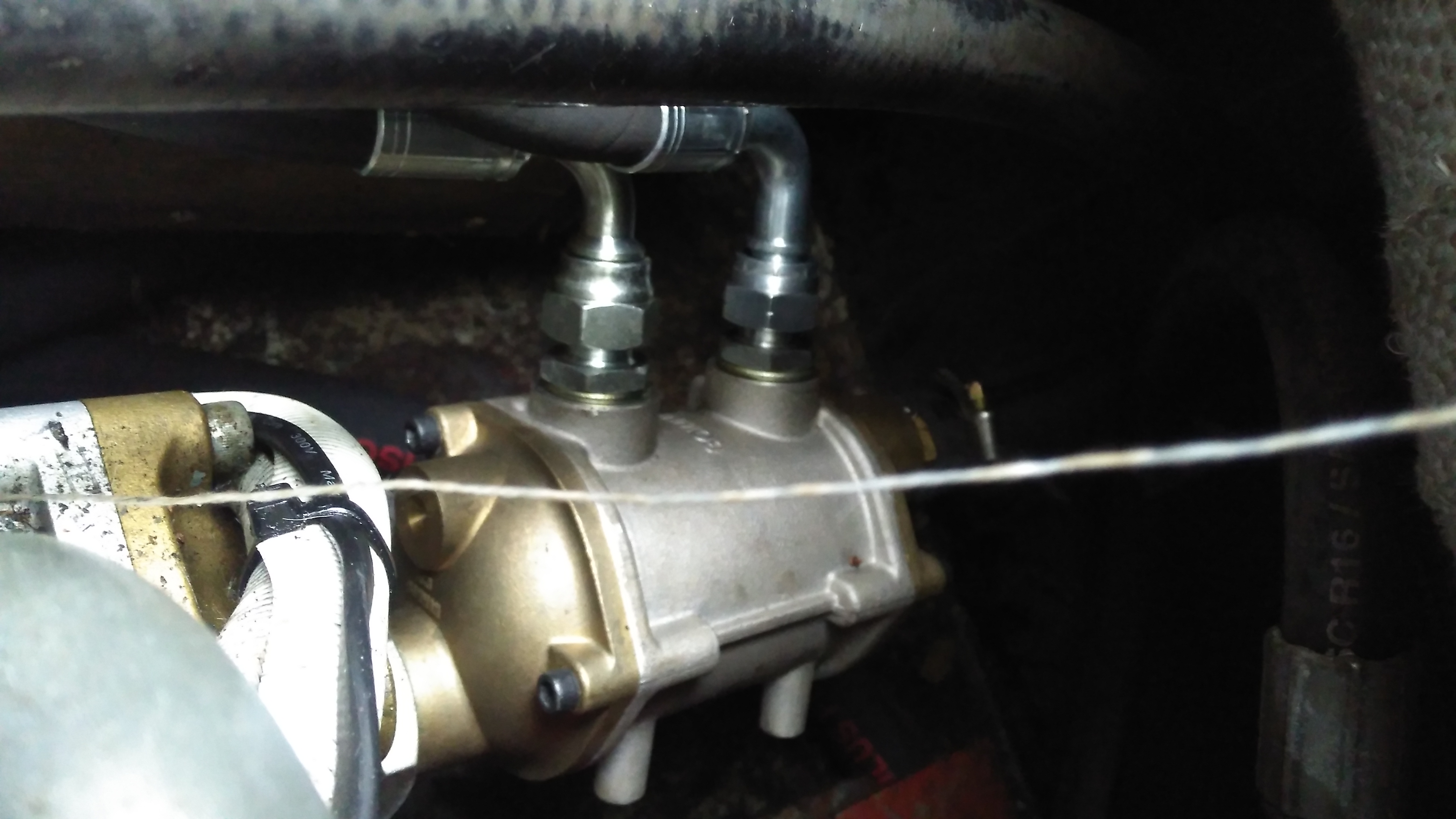
Temperature Senders
The temperature senders are standard automotive parts, and some adaptors were required to graft them into the oil lines of both systems. The senser’s 1/8″ NPT threads are here fitted into 1/2″ BSP hydraulic fittings.
Hydraulic Temperature Sender
Here’s the hydraulic oil sender installed in the drain line from the main propulsion pump, this should give me a pretty good idea of the temperature of the components in the system, the sender is earthed through the steel hydraulic oil tank.
Engine Oil Temperature Sender
The oil temperature sender is installed in the return line to the engine from the heat exchanger. This is measuring the oil temperature the bearings in the engine are being fed with.
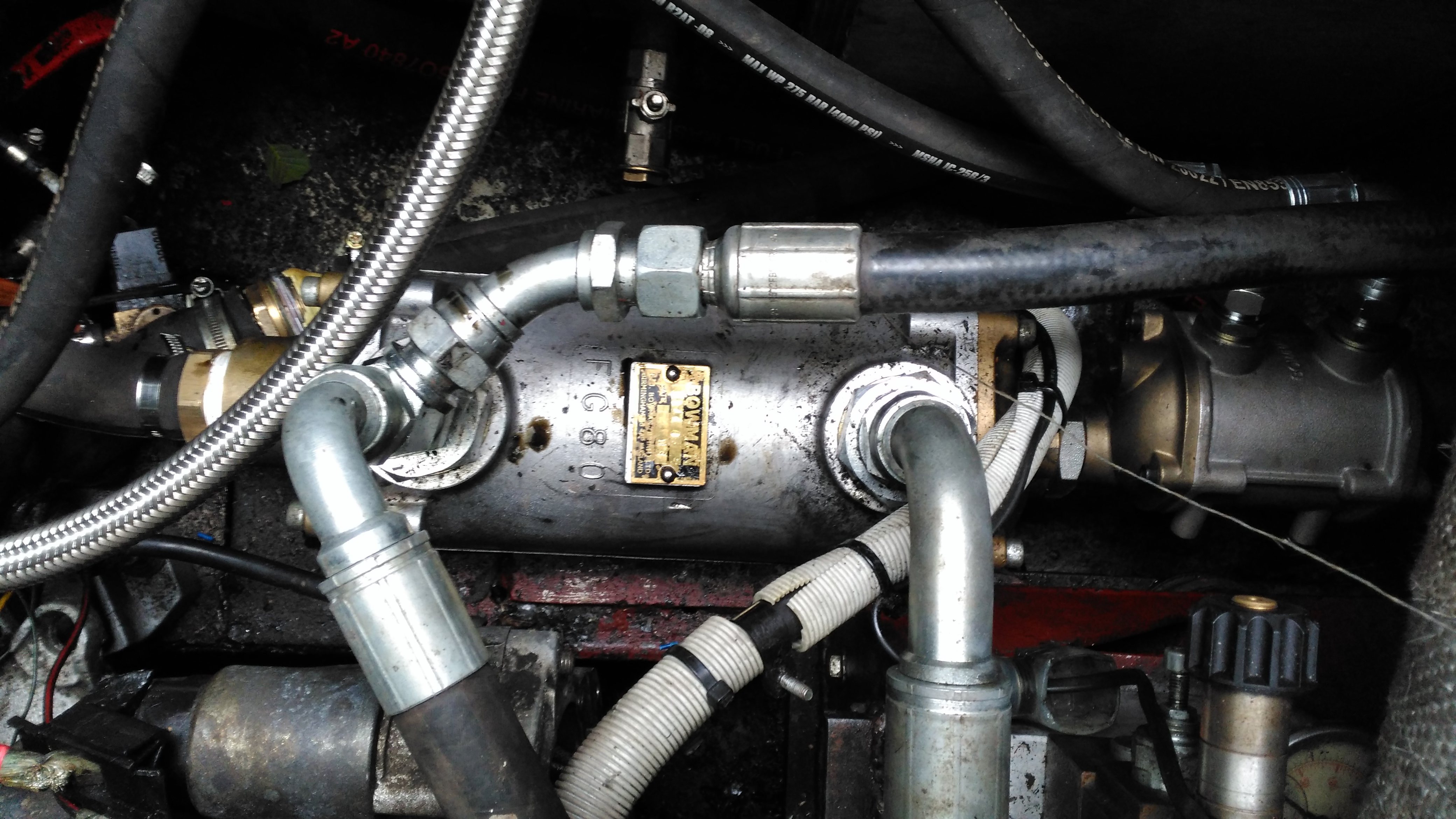
Hydraulic Oil Heat Exchanger
The stack of heat exchangers is located on the starboard side of the engine bay, the large one here is cooling the hydraulic oil, the auxiliary pump is continually circulating the oil from the tank through this, then into the return filter on the top of the tank.
Engine Oil Heat Exchanger
The engine oil is fed through this much smaller heat exchanger mounted on the back of the large hydraulic cooler, the last in the circuit before the water is discharged back overboard through a skin fitting.
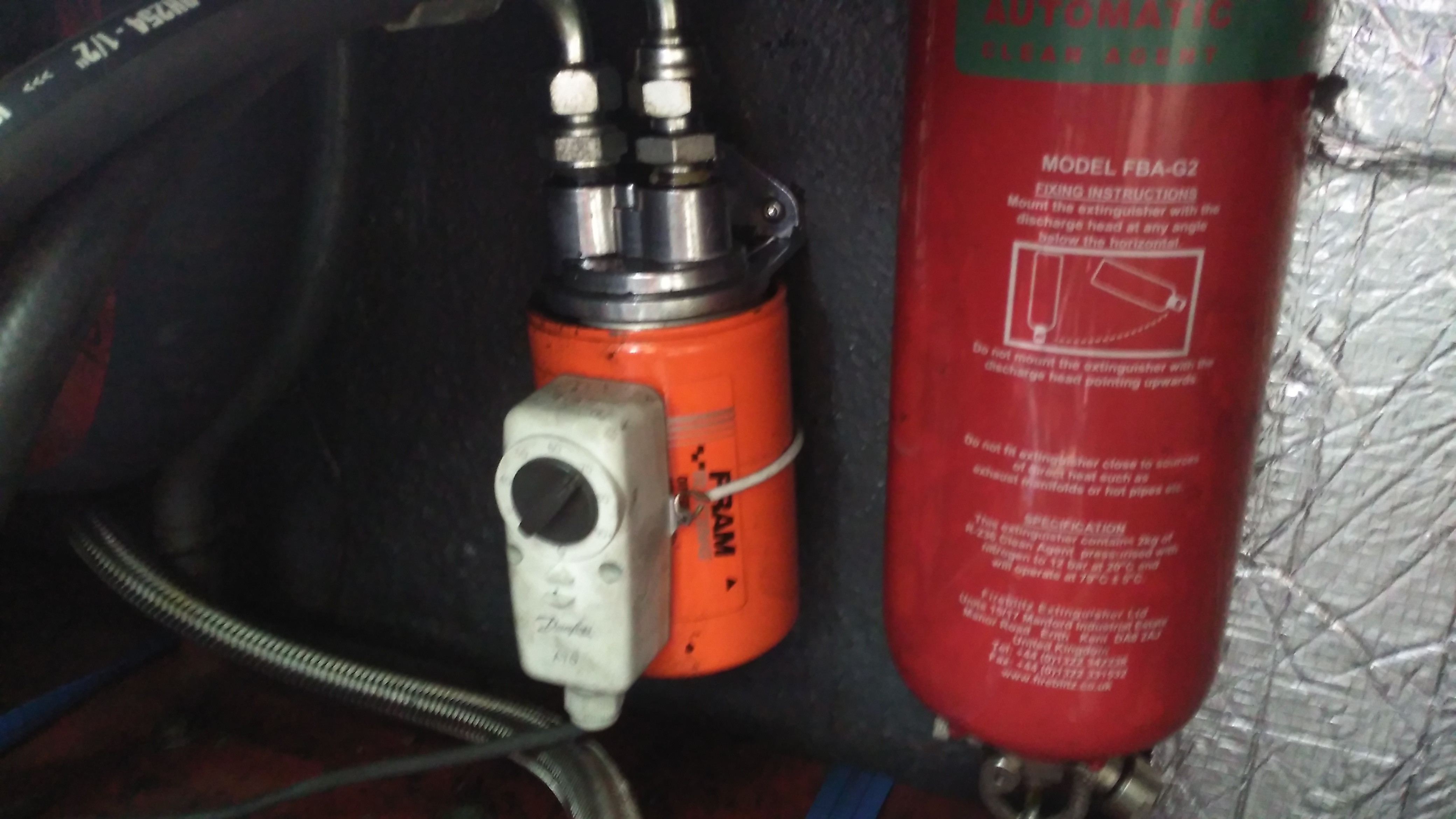
Remote Oil Filter
As we’ve got the diverter block on the side of the engine where the oil filter should be, a remote oil filter is fitted above the fuel tank. The thermostat strapped on operates the main engine bay ventilation fans, switching them on once the engine oil reaches 60°C.
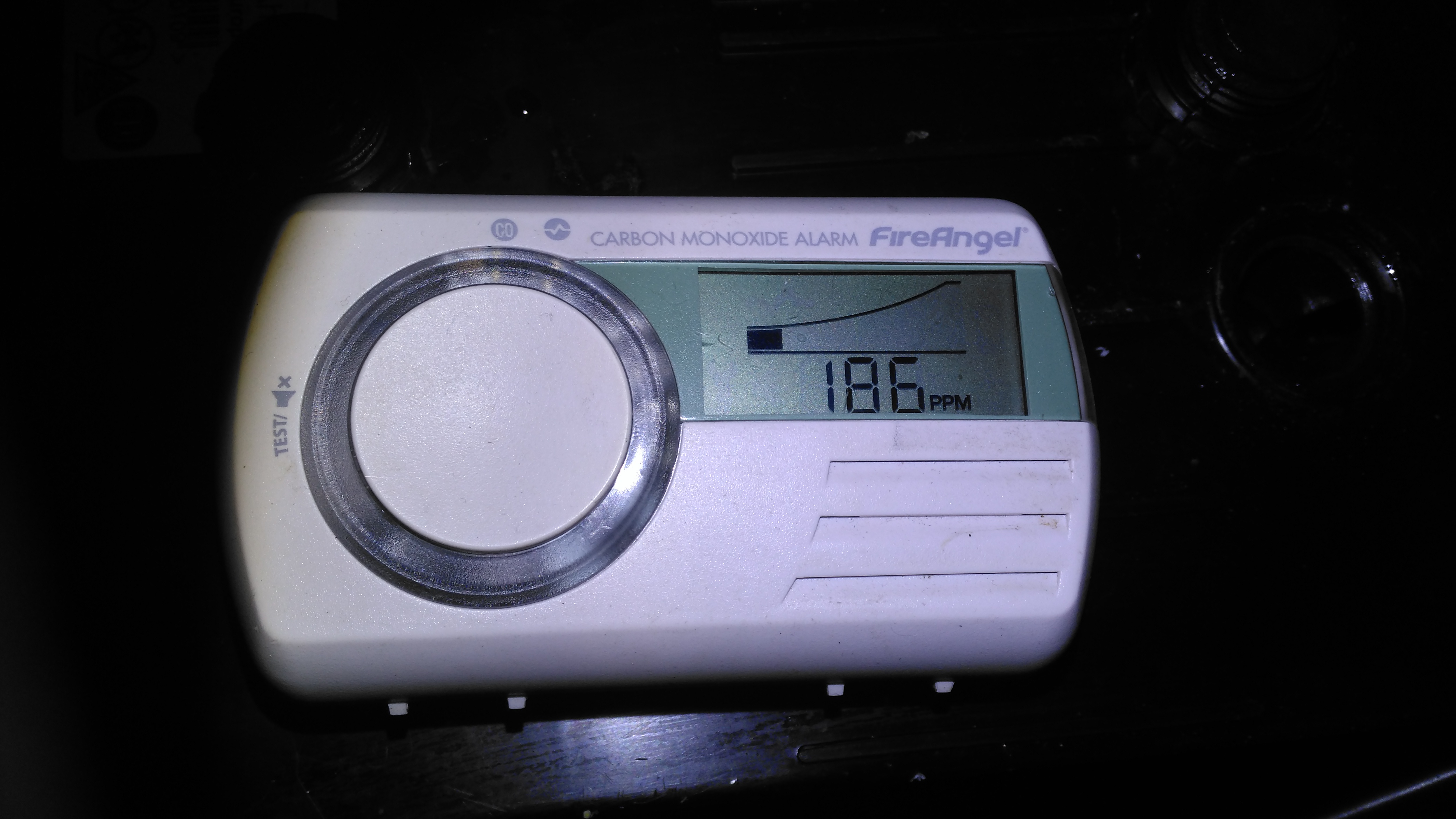
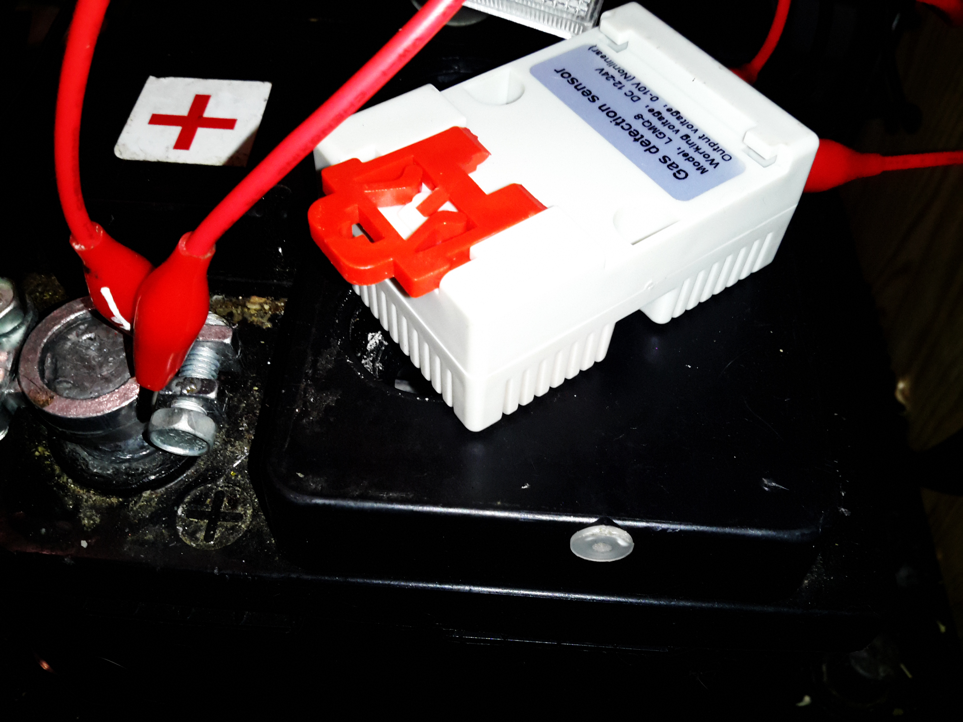
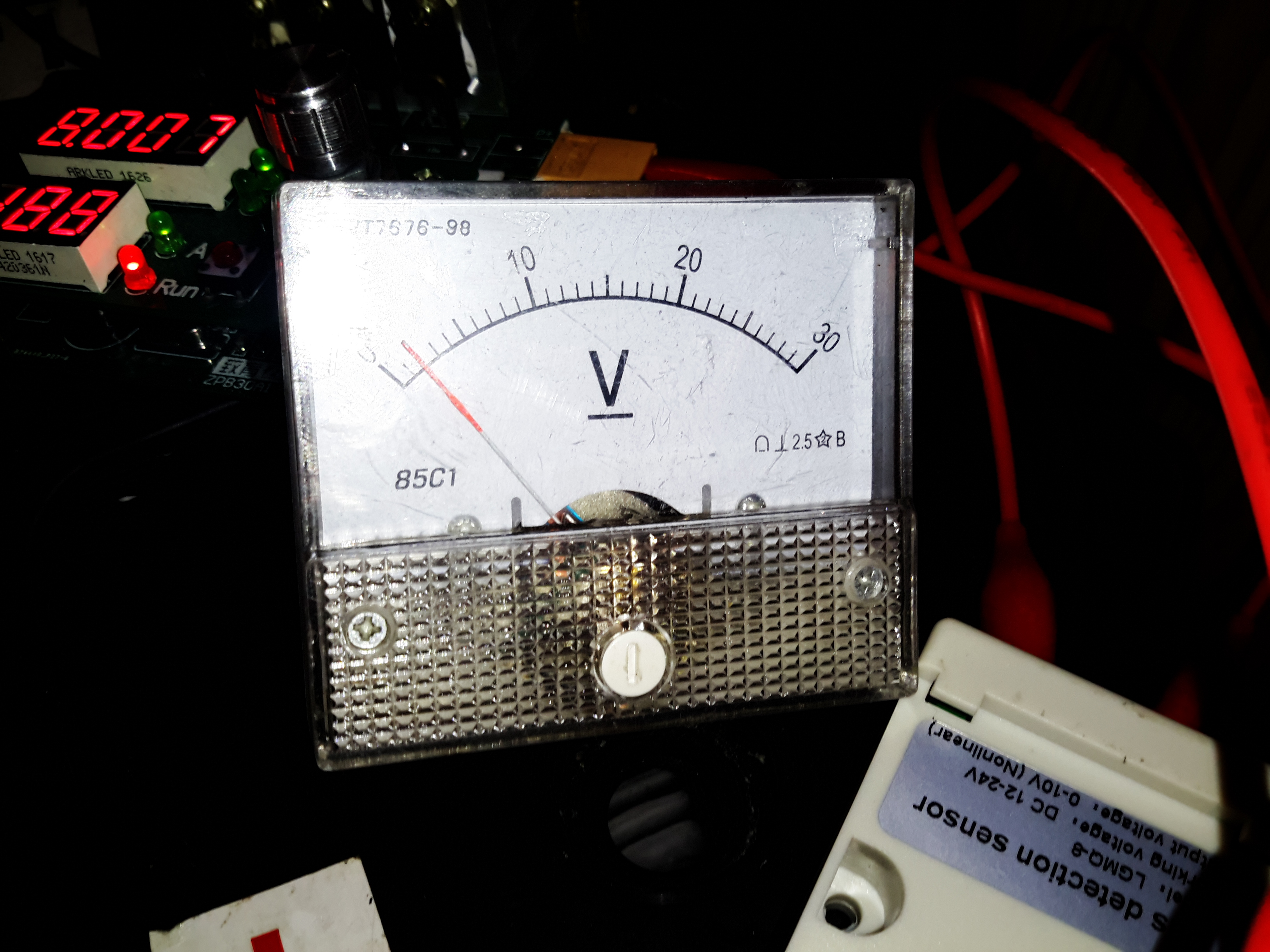
Here’s something different – below is a standard domestic carbon monoxide alarm, (I did a teardown of the same detector here), but in this case it’s not detecting any carbon monoxide, but another gas in the surrounding atmosphere. We recently had an issue with these detectors on board the boat, the alarms were sounding in the middle of the night, at ridiculous levels displayed, with no fuel-burning appliances running! While it didn’t become obvious at the time, the gas being detected was hydrogen, given off from the house battery bank while they were on charge.
CO Detector
I have long been aware of the fact that electrochemical gas sensors have some cross-sensitivity, and sensors are available that are specifically designed to not respond to other gases (hydrogen in particular, as this gas is actually part of the sensor reaction. Much more information about the subject is over here). I’ve no doubt these more industrial grade sensors are much more expensive than the cheap kind used in domestic alarms though, not to mention there aren’t usually massive lead-acid battery banks in houses, so the concept of having hydrogen in the air doesn’t usually happen.
However, I’ve seen plenty of these exact type, and other types of the same brand used on boats. The user manual for this particular alarm doesn’t mention the possibility of cross-sensitivity though, and this could lead someone to doubt their alarm is working correctly, and to stop trusting it or remove it entirely due to false triggering.
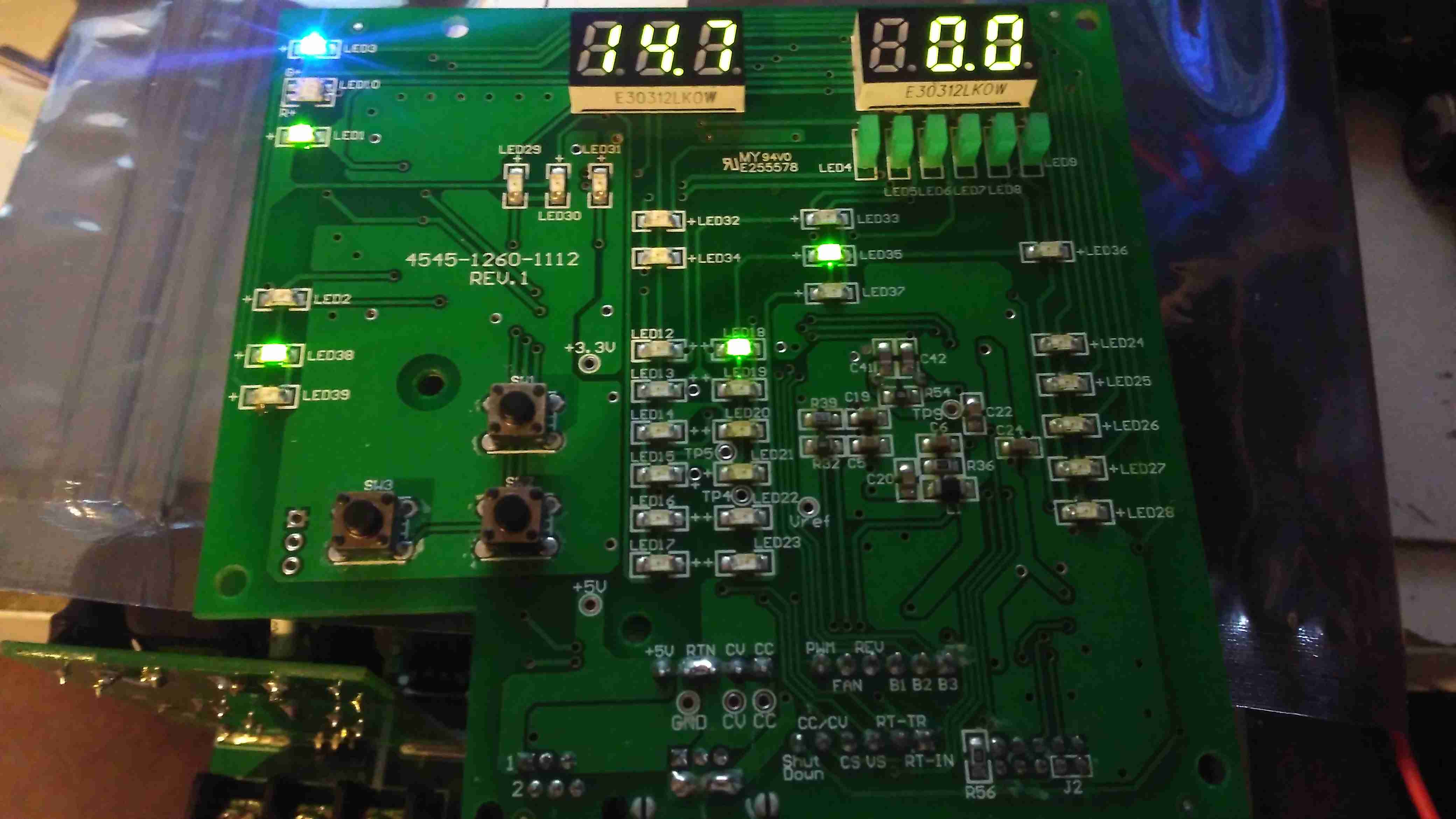
As I’ve not been able to find any data on the sensor used in this detector, I don’t know how sensitive it is to hydrogen, the image above was taken with an alarm placed directly over the cell opening of a large lead-acid battery on charge at 14.7v to deliberately cause some gassing. This was the highest reading obtained, the detector didn’t take long to respond either. As the gas mix coming out of the cell is 2:1 H²/O² this reading is clearly low, but it’s still plenty enough to sound the alarm within a few minutes.
For us on boats, with potentially explosive gas mixtures being able to gather this cross sensitivity is potentially a good thing – the alarm made sure we were well aware of something going wrong before a dangerous concentration was present. (Hydrogen is flammable in air between 4% & 75%).
To prevent this happening in future, I’ll be installing some forced ventilation into the battery compartment, triggered by a hydrogen sensor. More to come on this soon!
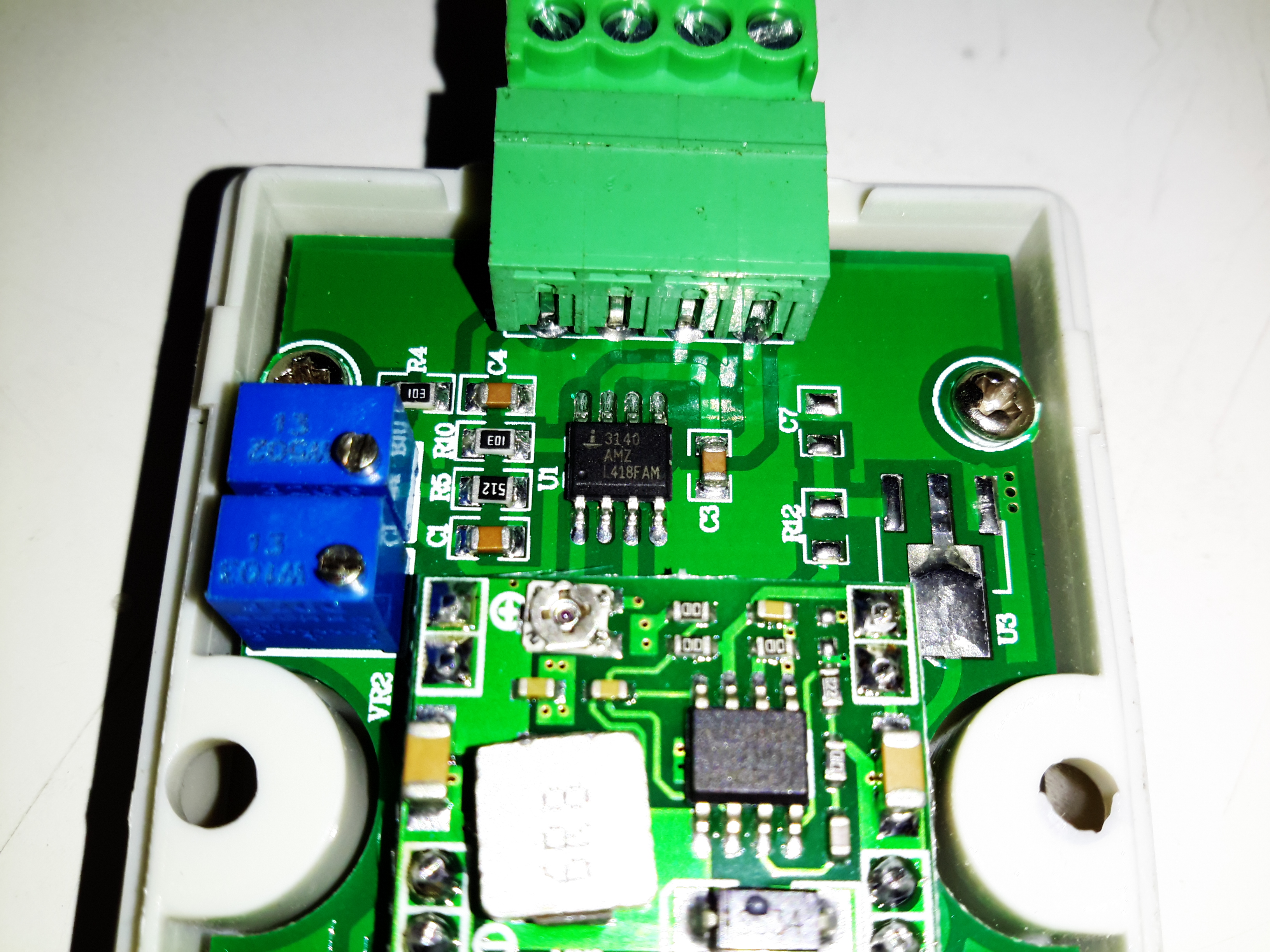
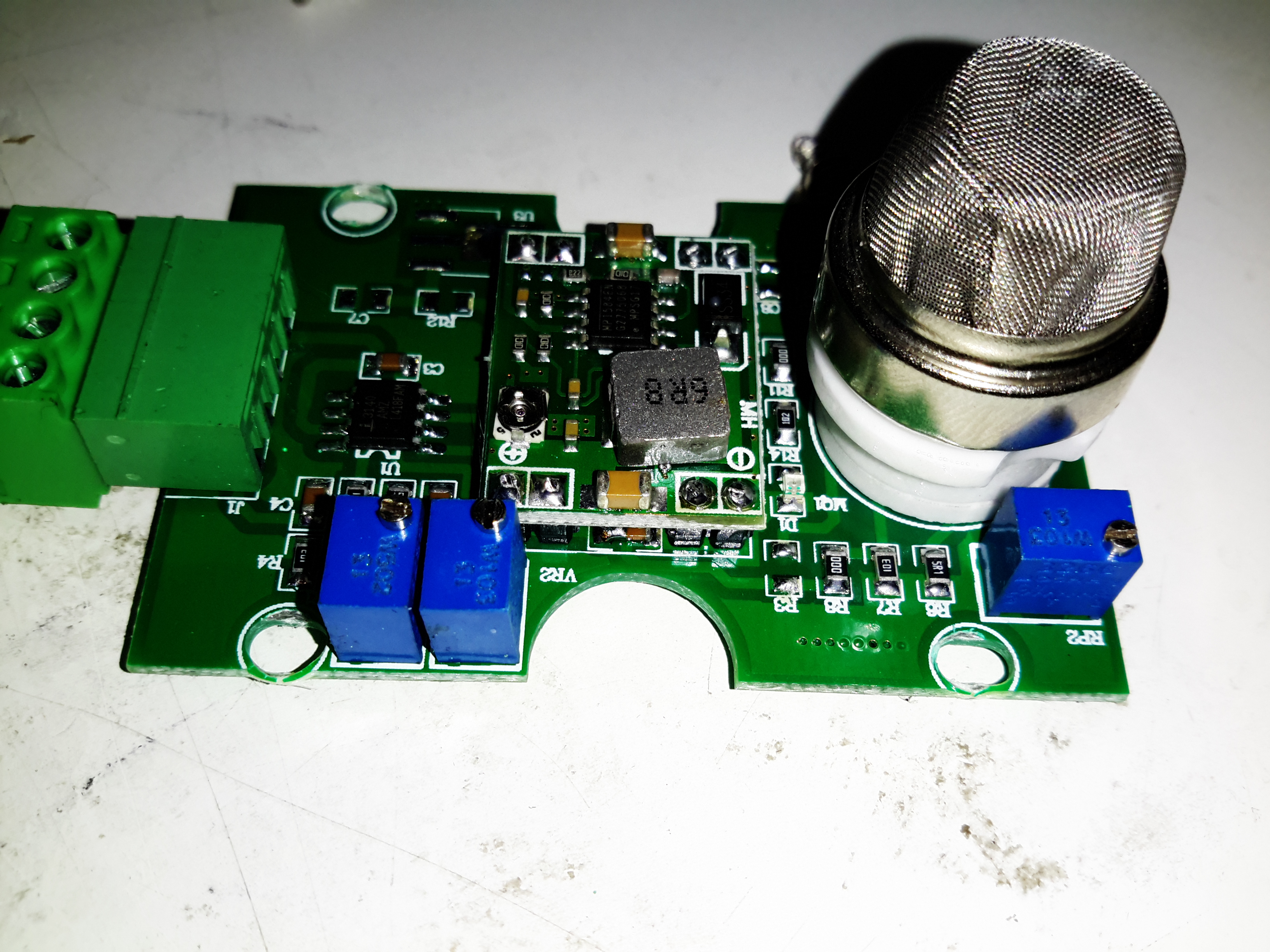
Since the batteries on board the boat are located in the cabin, I’ve noticed something rather odd with the Carbon Monoxide detectors: when the batteries are being charged, the CO alarms are triggering on the H² that’s being released. Since the last thing we need is hydrogen building up to levels that could become explosive (which for H² is a very wide range, from 4% to 75% in standard atmospheric conditions, it also has a very low activation energy), some venting of the battery compartment is required while the batteries are being float charged. These SnO² based sensors are very cheap, so I figured I’d give one of them a go.
This particular module has a DIN rail mounting clip on the back, along with holes to mount with screws. It’s signal output is standard industrial 0-10v.
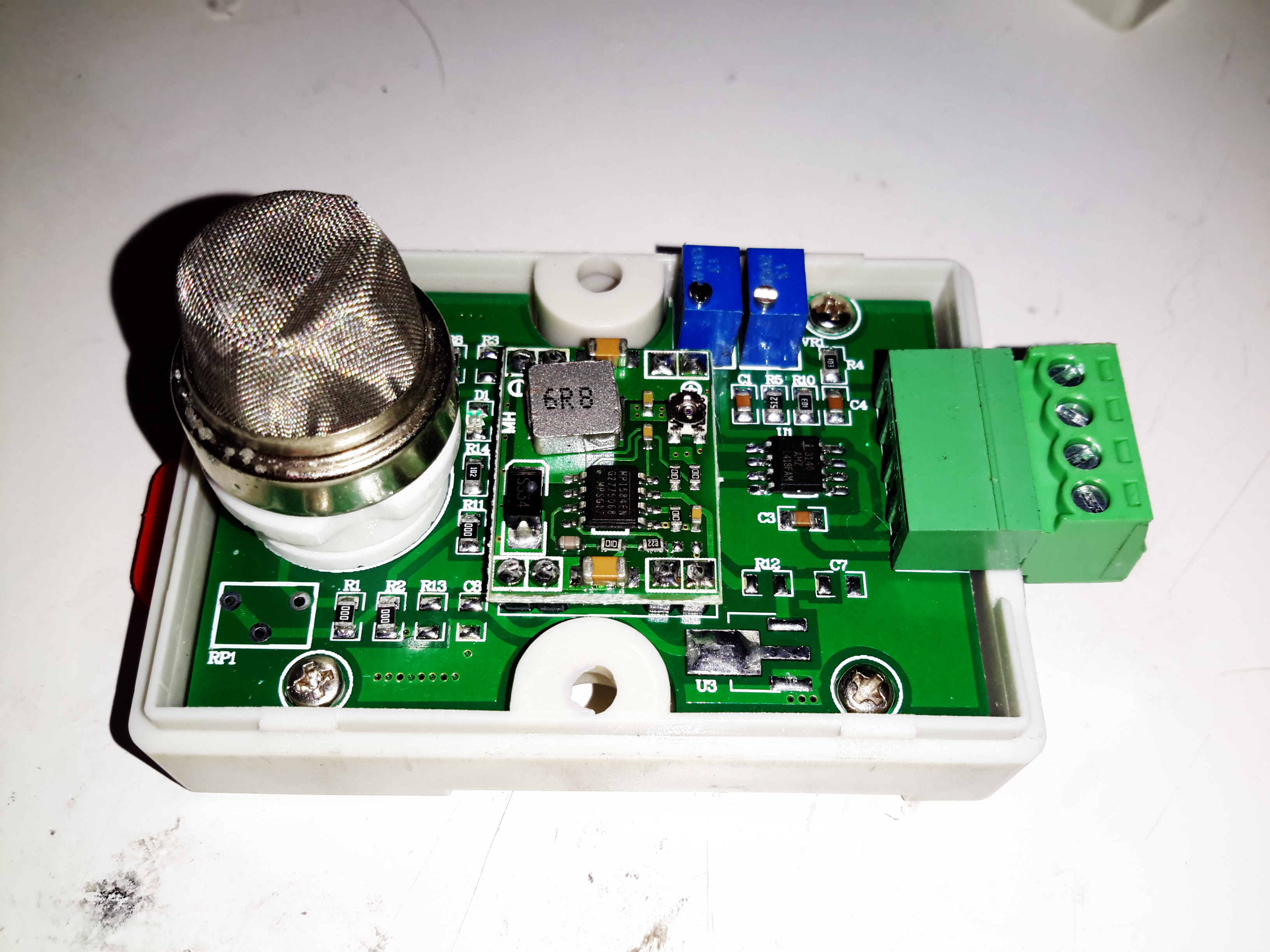
Cover Removed
Popping the cover off reveals some adjustment pots, a DC-DC converter & a single amplifier on the output. The sensor itself is plugged into a ceramic socket, so this could be replaced in the future if needed.
Output Amplifier
The output Op-Amp is an Intersil CA3140 4.5MHz BiMOS, with FET input & bipolar output stages.
Adjustment Pots
There’s a trio of potentiometers for adjusting the sensor.
Potentiometer
Function
RP2
Sensor Load Resistance Adjust
VR1
Sensitivity Adjust
VR2
Ref. Voltage Adjust
PCB Bottom
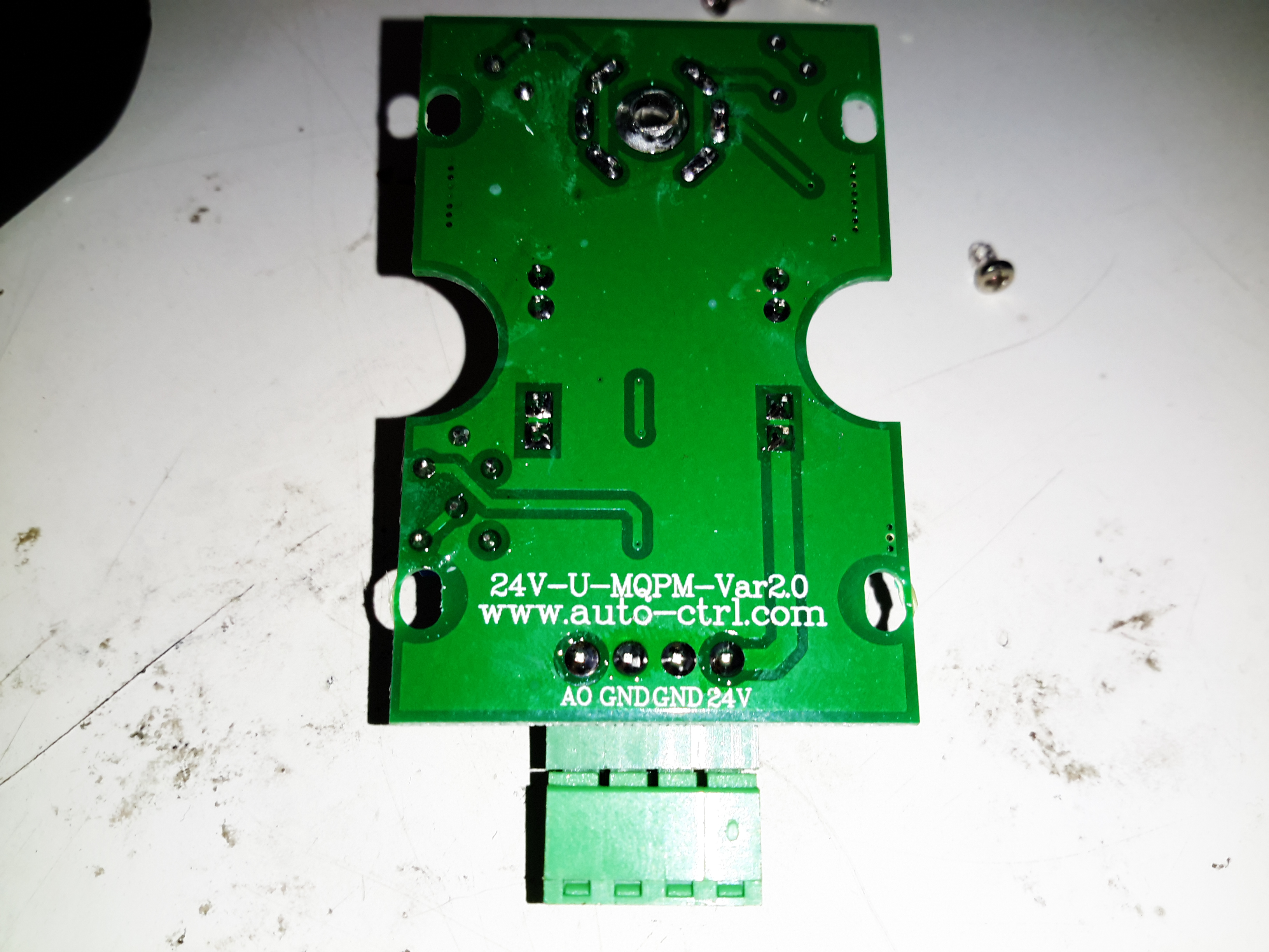
The bottom of the PCB is pretty sparse, but there’s a model number here & a website. The guys that make this seem to specialize in sensing modules.
Sensor In Cell
To give this unit a test, I removed the cell cap from one of my spare lead acids & placed the sensor head into the opening while I was giving it a topping charge. In this position any gas given off by the charging battery would instantly rise up into the sensor.
Output
Once the sensor has heated up & stabilised, the base voltage with no hydrogen present was about 1 volt. As the battery voltage rose to 13.2v the sensor began to detect some hydrogen, with the voltage rising to about 9 volts with the battery voltage at topping charge level of 14.4v.
These sensors definitely work, but there’s no calibration so it’s not possible to say how much gas is present, but this isn’t a problem for my application.
More to come when the ventilation system is installed in the battery compartment!
I wrote a few weeks ago about replacing the hot water circulating pump on the boat with a new one, and mentioned that we’d been through several pumps over the years. After every replacement, autopsy of the pump has revealed the failure mode: the first pump failed due to old age & limited life of carbon brushes. The second failed due to thermal shock from an airlock in the system causing the boiler to go a bit nuts through lack of water flow. The ceramic rotor in this one just cracked.
The last pump though, was mechanically worn, the pump bearings nicely polished down just enough to cause the rotor to stick. This is caused by sediment in the system, which comes from corrosion in the various components of the system. Radiators & skin tanks are steel, engine block cast iron, back boiler stainless steel, Webasto heat exchanger aluminium, along with various bits of copper pipe & hose tying the system together.
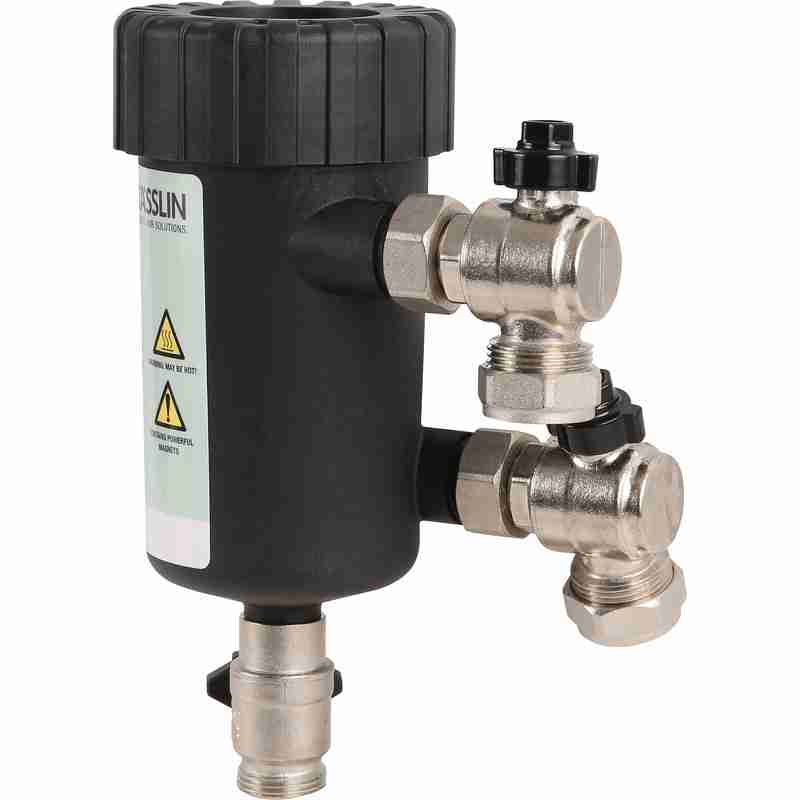
The use of dissimilar metals in a system is not particularly advisable, but in the case of the boat, it’s unavoidable. The antifreeze in the water does have anti-corrosive additives, but we were still left with the problem of all the various oxides of iron floating around the system acting like an abrasive. To solve this problem without having to go to the trouble of doing a full system flush, we fitted a magnetic filter:
Mag Filter
This is just an empty container, with a powerful NdFeB magnet inserted into the centre. As the water flows in a spiral around the magnetic core, aided by the offset pipe connections, the magnet pulls all the magnetic oxides out of the water. it’s fitted into the circuit at the last radiator, where it’s accessible for the mandatory maintenance.
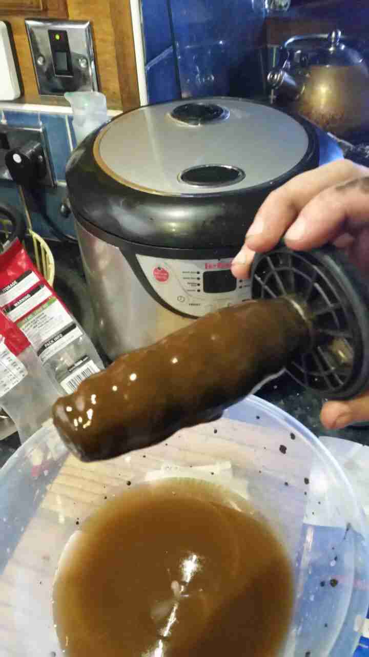
Sludge
Now the filter has been in about a month, I decided it would be a good time to see how much muck had been pulled out of the circuit. I was rather surprised to see a 1/2″ thick layer of sludge coating the magnetic core! The disgusting water in the bowl below was what drained out of the filter before the top was pulled. (The general colour of the water in the circuit isn’t this colour, I knocked some loose from the core of the filter while isolating it).
If all goes well, the level of sludge in the system will over time be reduced to a very low level, with the corrosion inhibitor helping things along. This should result in much fewer expensive pump replacements!
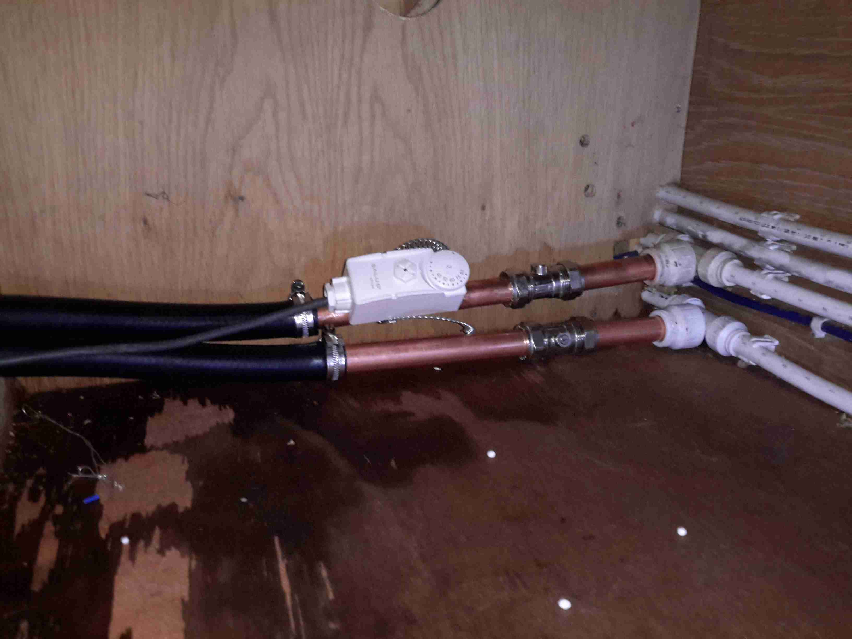
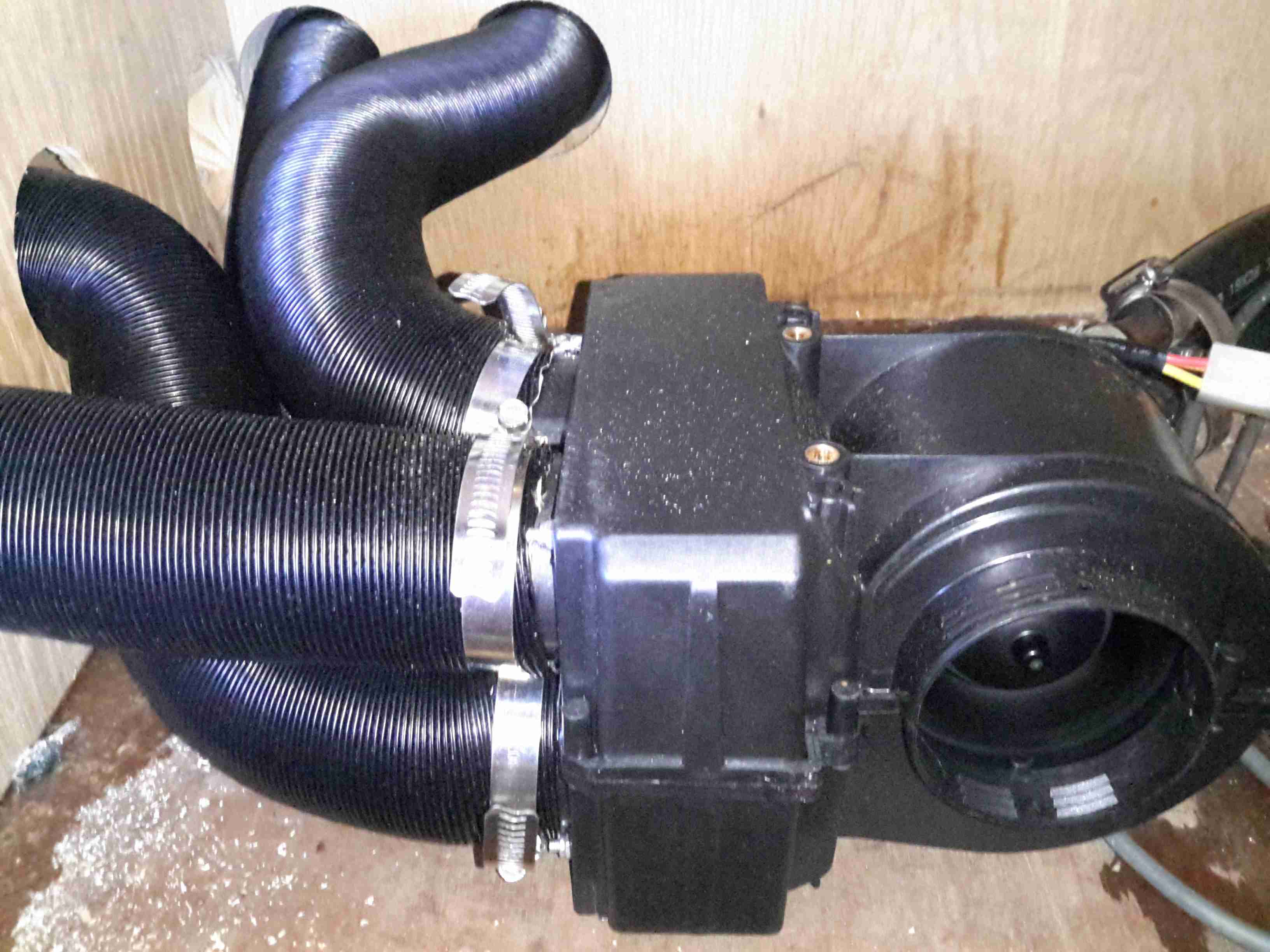
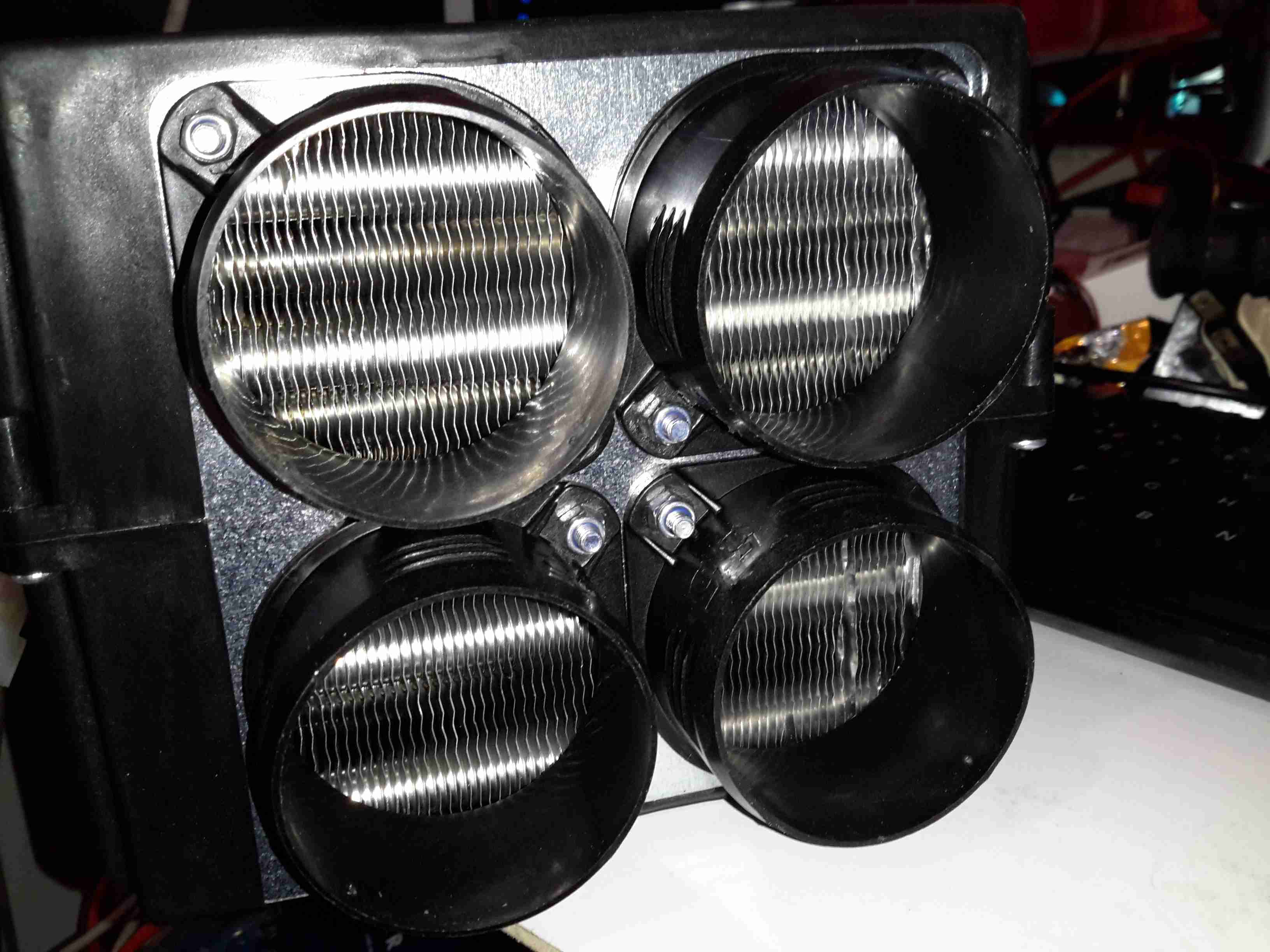
Here the pipework feeding the matrix of the blower unit has been tapped into the heating circuit, the first radiator on the loop is just out of shot to the right, this is all tucked away under the bed in one of the cabins. The pipestat is attached to the flow from the boiler, this will switch on the blower once hot water starts flowing through the system. Isolation valves have been fitted to make the inevitable maintenance of the matrix unit easier, as the system is pressurised to 14PSI, dropping the pressure out of the system without making quite a mess is difficult.
Heater Matrix & Ducting
The heater itself is mounted on the other side of a wooden partition in the small space left under a shelf. This made installing the unit like trying to plumb in a radiator through a letterbox ;). 4 60mm ducts snake off to the vents mounted in the wall.
Water Connections
The hot water hoses appear through a hole in the timber to connect to the matrix unit, with some 15mm pipe in between as reducers from the 3/4″ hose to the 1/2″ attached to the matrix itself. The blower is wired in low speed mode only, as running it any faster makes far too much noise from the vents.
As a heating solution, this unit works well onboard. Within a 10 minutes of the diesel heater firing up, the blower automatically comes on thanks to the thermostat, and blows plenty of hot air into the saloon to keep the cold at bay.
With the installation of the new diesel fired heater we’ve noticed a small problem – since the only heat source in the saloon is the stove, even with the diesel heater fired up the temperature doesn’t really change much, as the heat from the radiators in the both the cabins & the head isn’t spreading far enough.
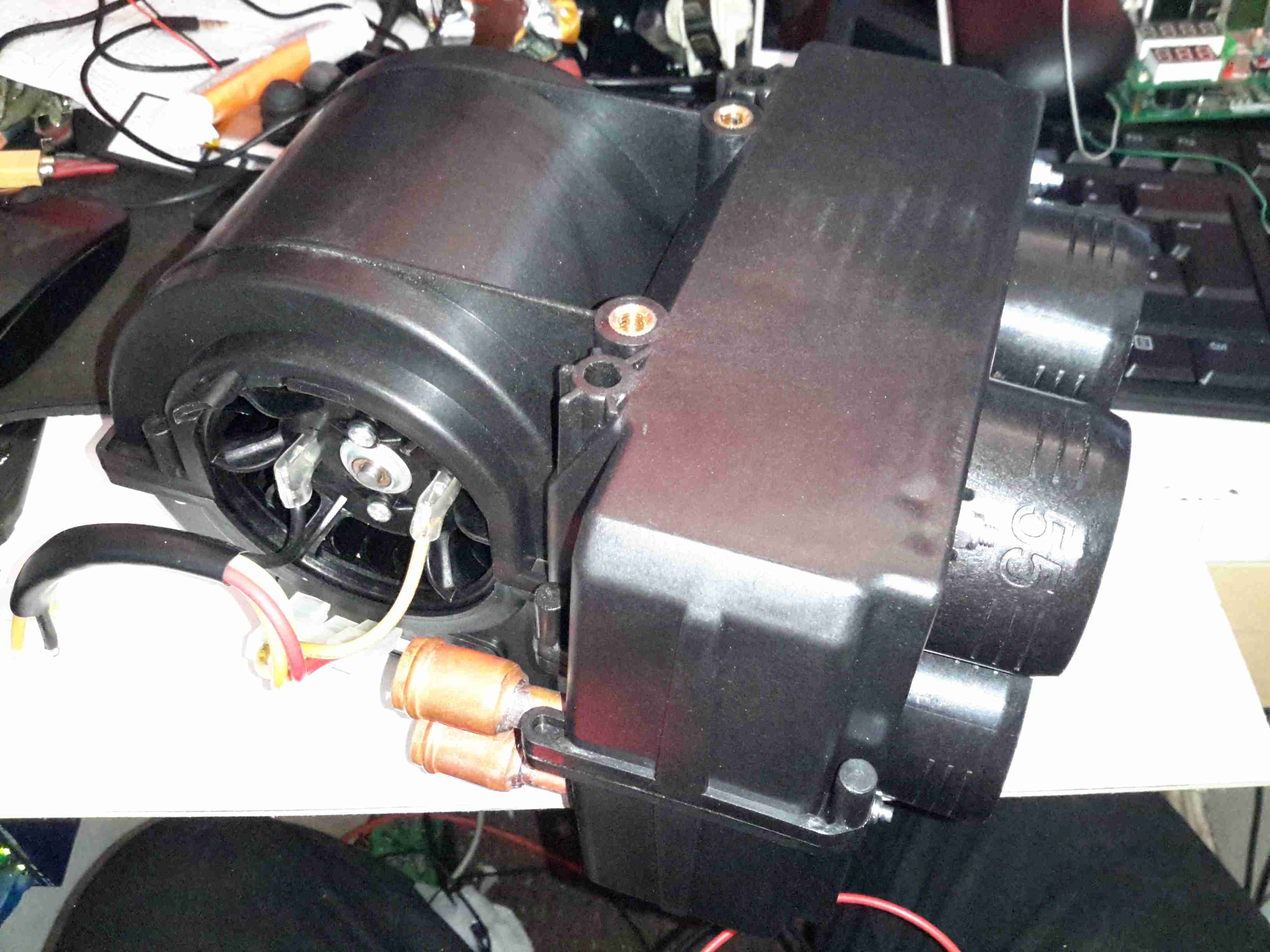
The solution to this problem is obviously an extra radiator in the saloon, however there isn’t the space to fit even a small domestic-style radiator. eBay turned up some heater matrix units designed for kit cars & the like:
3.8kW Matrix
These small heater matrix units are nice & compact, so will fit into the back of a storage cupboard next to the saloon. Rated at a max heat output of 3.8kW, just shy of the stove’s rated 4kW output power, this should provide plenty of heating when we’re running the diesel heater rather than the fire.
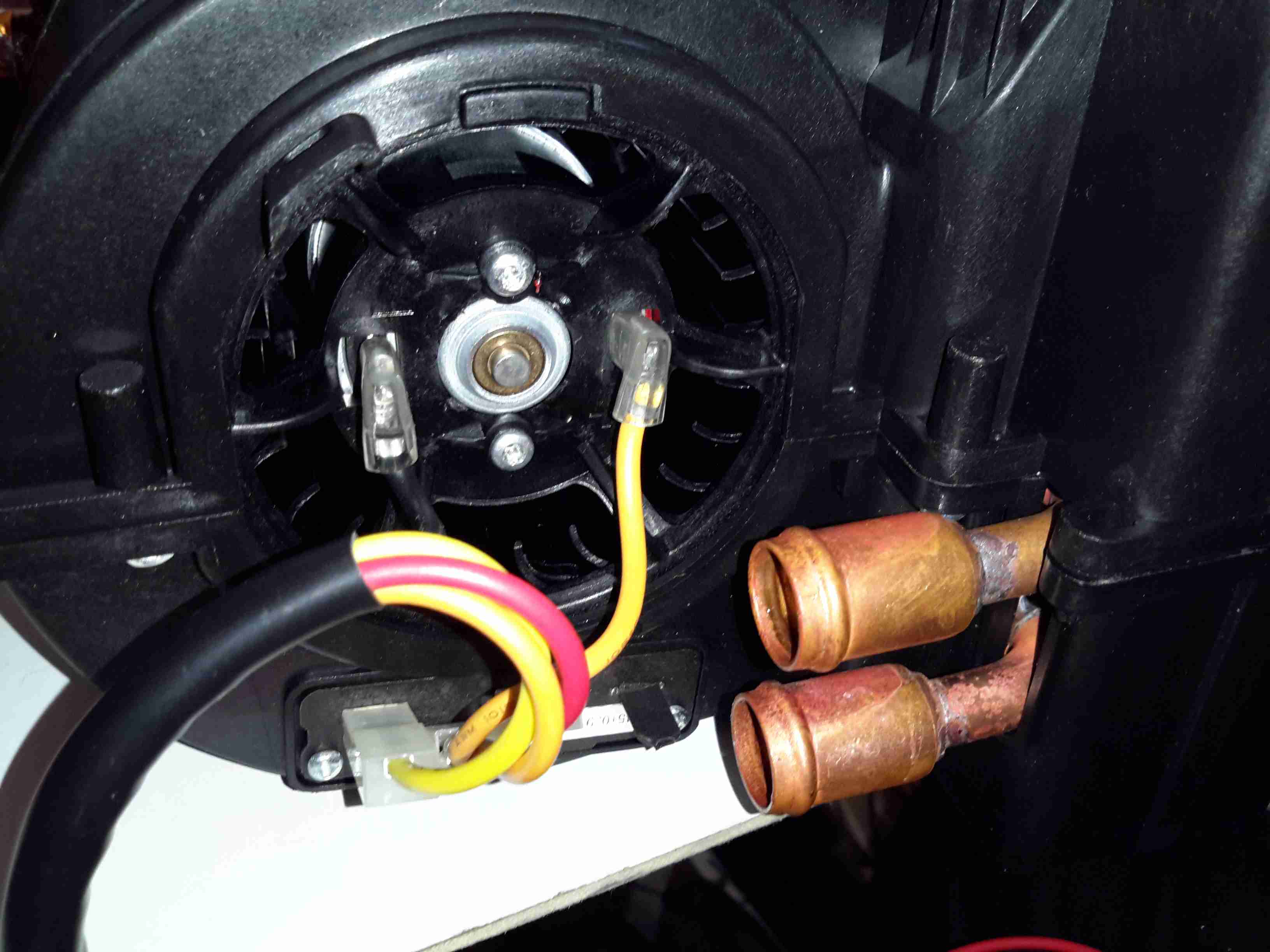
Water & Power
The blower motor has a resistor network to provide 3 speeds, but this probably won’t be used in this install, water connections are via 15mm copper tails. The current plan is to use a pipe thermostat on the flow from the boiler to switch on the blower when the water temperature reaches about 40°C.
Hot Air Outlets
The hot air emerges from the matrix via 4 55mm duct sockets. This gives enough outlets to cover both the saloon & the corridor down to the cabins.
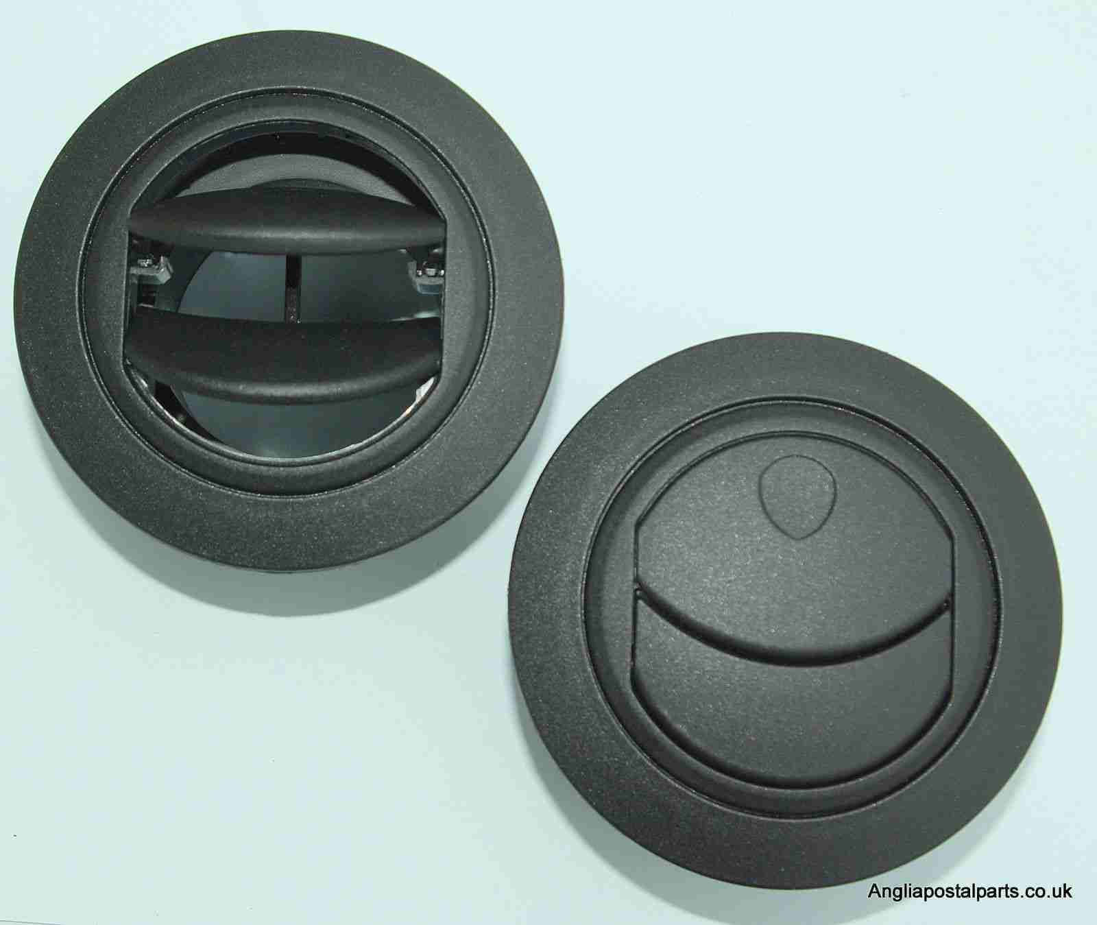
Hot Air Vents
Standard 60mm Eberspacher style vents will be used to point the warmth where it’s needed.
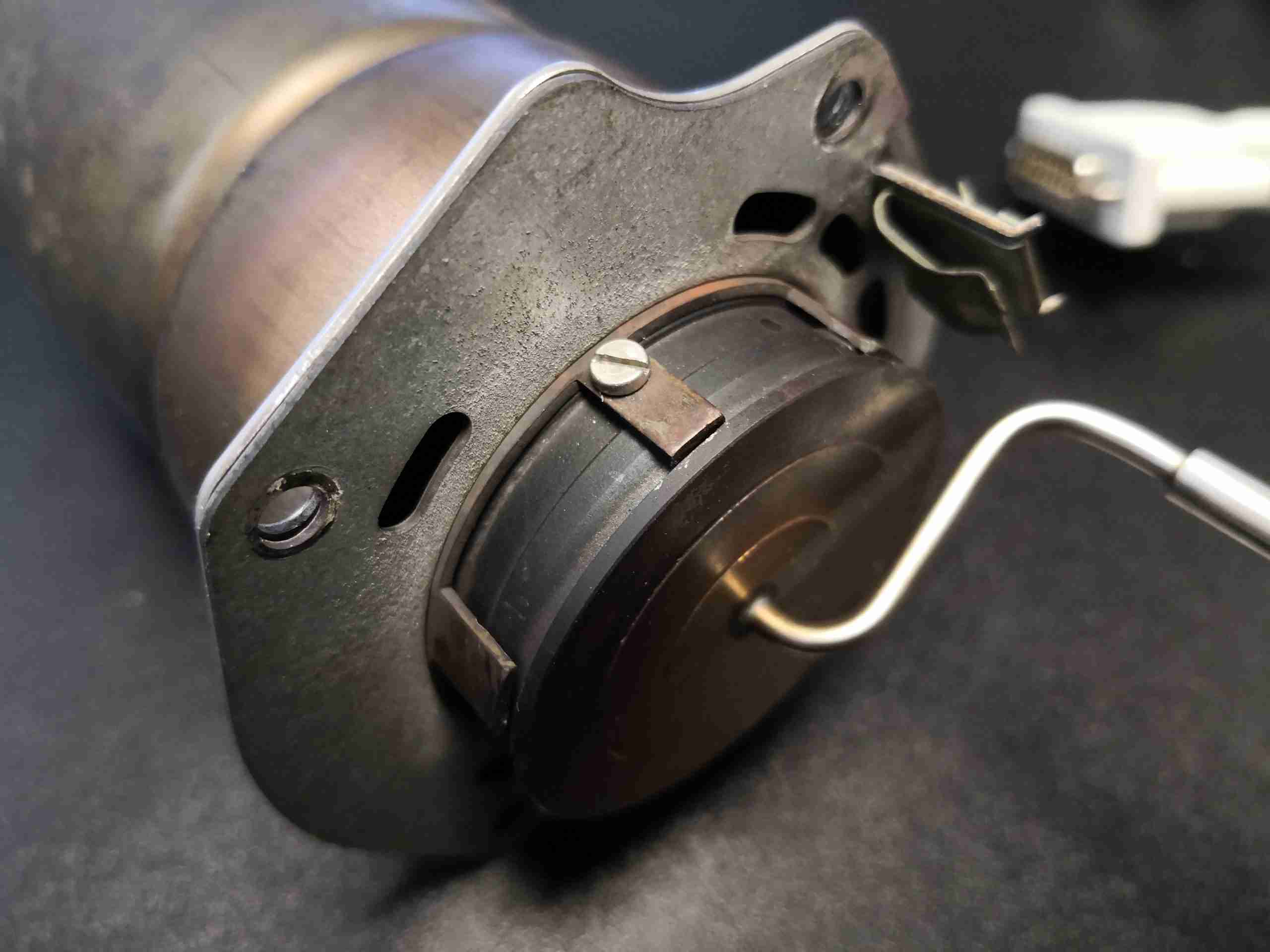
With some recent upgrades to the boat’s heating system, the hot water circulation pumps we’ve been using are becoming far too small for the job. After the original Johnson Marine circulation pump died of old age (the brushes wore down so far the springs ate the commutator) some time ago, it was replaced with a Pierburg WUP1 circulation pump from a BMW. (As we’re moored next to a BMW garage, these are easily obtainable & much cheaper than the marine pumps).
WUP1 Cutaway
These are also brushless, where as the standard Johnson ones are brushed PM motors – the result here is a much longer working life, due to fewer moving parts.
The rated flow & pressure on these pumps is pretty pathetic, at 13L/min at 0.1bar head pressure. As the boat’s heating system is plumbed in 15mm pipe instead of 22mm this low pressure doesn’t translate to a decent flow rate. Turns out it’s pretty difficult to shove lots of water through ~110ft of 15mm pipe ;). Oddly enough, the very low flow rate of the system was never a problem for the “high output” back boiler on the stove – I suspect the “high output” specification is a bit optimistic.
This issue was recently made worse with the addition of a Webasto Thermo Top C 5kW diesel-fired water heater, which does have it’s own circulation pump but the system flow rate was still far too low to allow the heater to operate properly. The result was a rapidly cycling heater as it couldn’t dump the generated hot water into the rest of the system fast enough.
The easiest solution to the problem here is a larger pump with a higher head pressure capability. (The more difficult route would be completely re-piping the system in 22mm to lower the flow resistance). Luckily Pierburg produce a few pumps in the range that would fit the job.
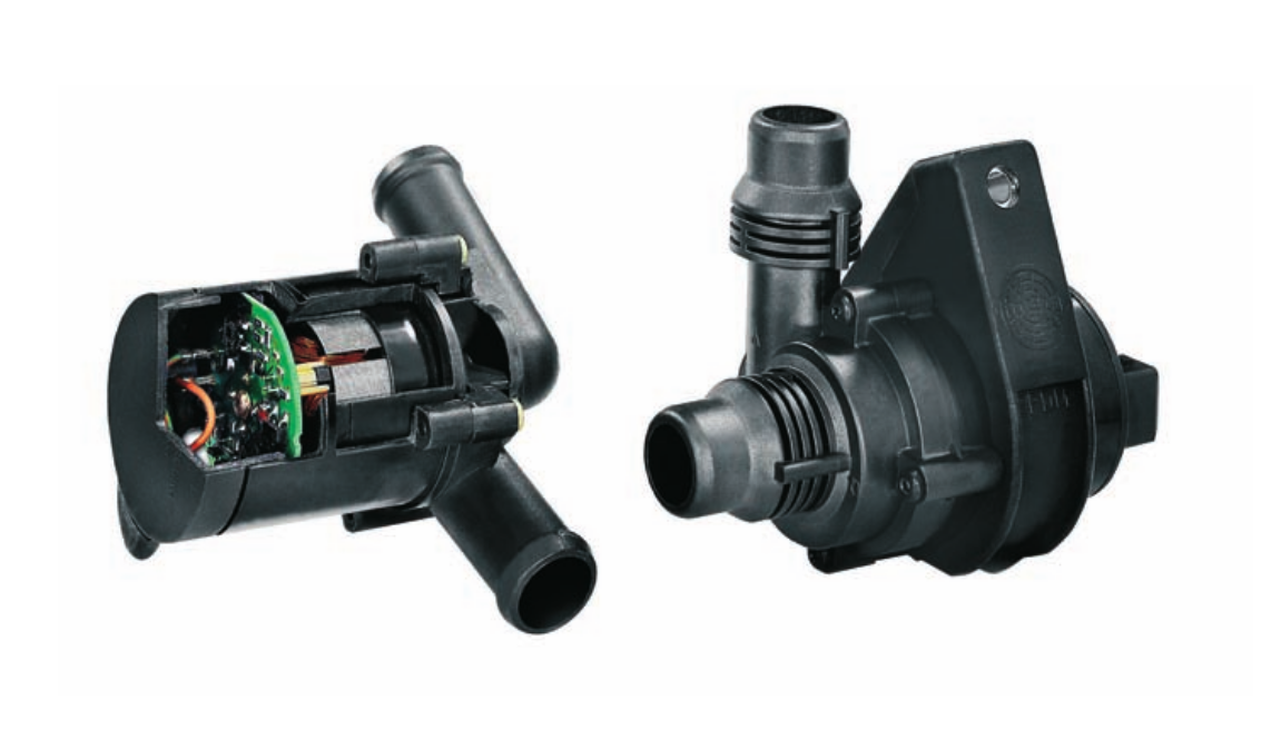
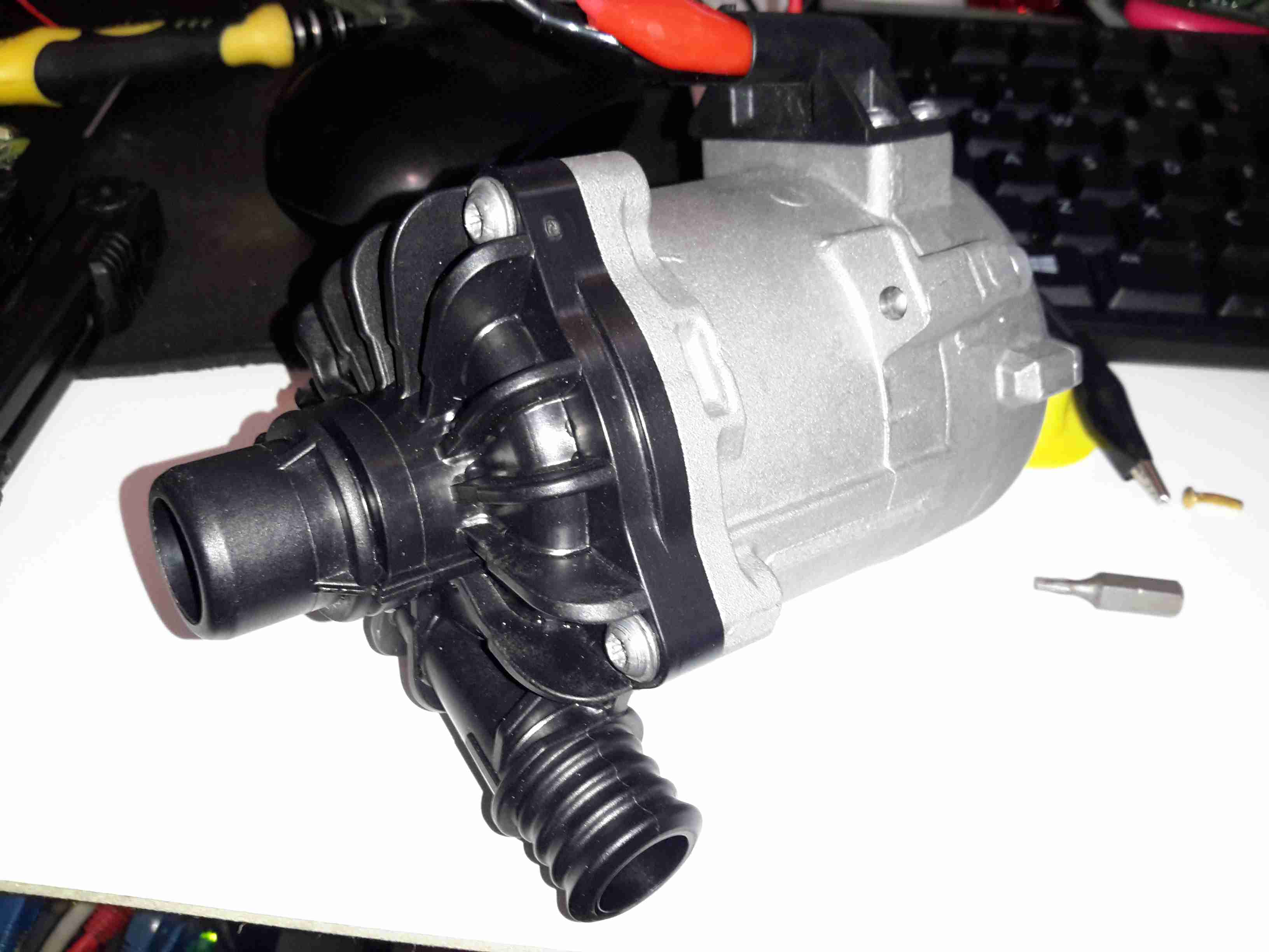
Pierburg CWA-50
Here’s the next size up from the original WUP1 pump, the CWA50. These are rated at a much more sensible 25L/min at 0.6bar head pressure. It’s physically a bit larger, but the connector sizes are the same, which makes the install onto the existing hoses easier. (For those that are interested, the hose connectors used on BMW vehicles for the cooling system components are NormaQuick PS3 type. These snap into place with an O-Ring & are retained by a spring clip).
The CWA50 draws considerably more power than the WUP1 (4.5A vs 1.5A), and are controllable with a PWM signal on the connector, but I haven’t used this feature. The PWM pin is simply tied to the positive supply to keep the pump running at maximum speed.
Once this pump was installed the head pressure immediately increased on the gauge from the 1 bar static pressure to 1.5 bar, indicating the pump is running at about it’s highest efficiency point. The higher water flow has so far kept the Webasto happy, there will be more to come with further improvements!
CWA-50 Pump Teardown
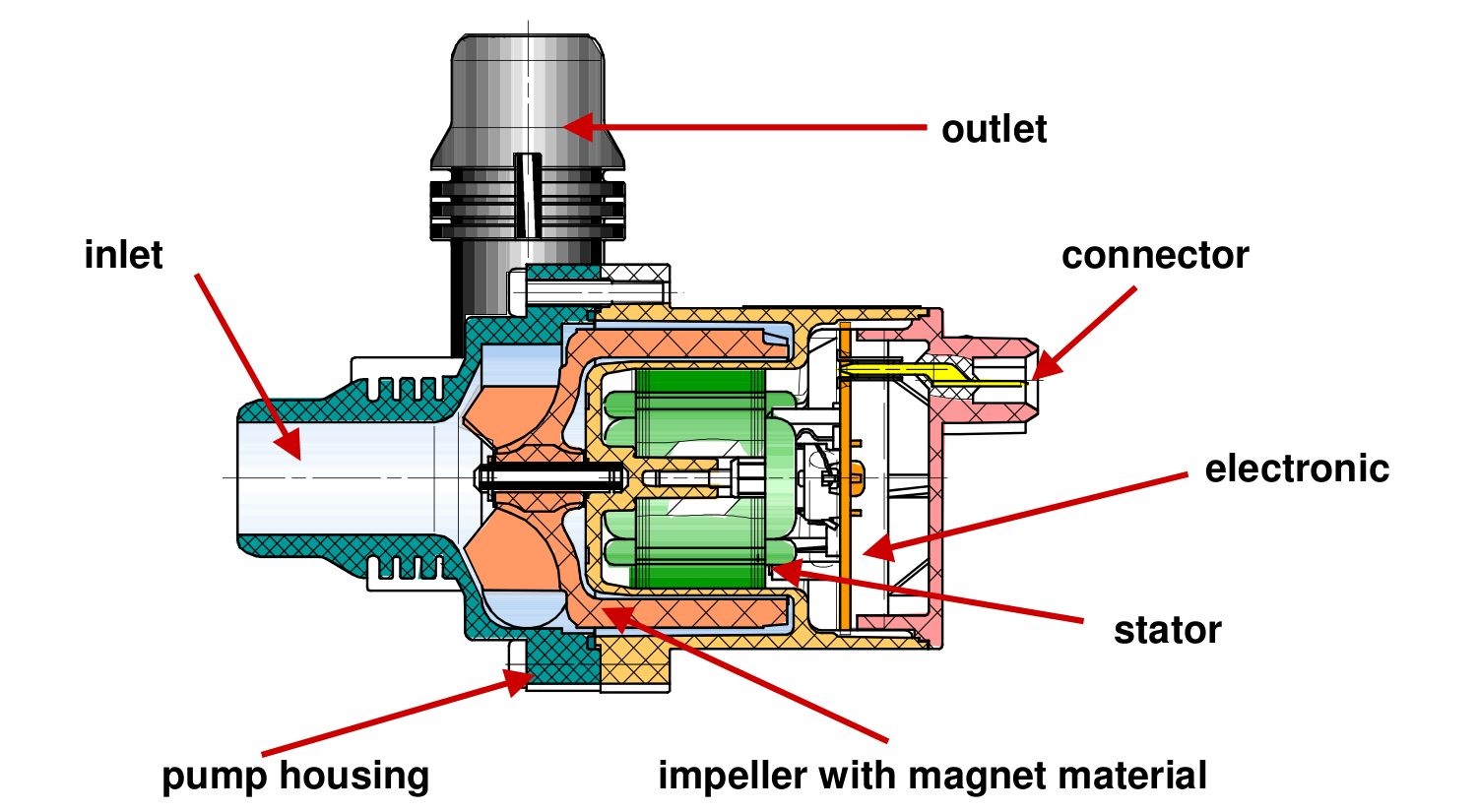
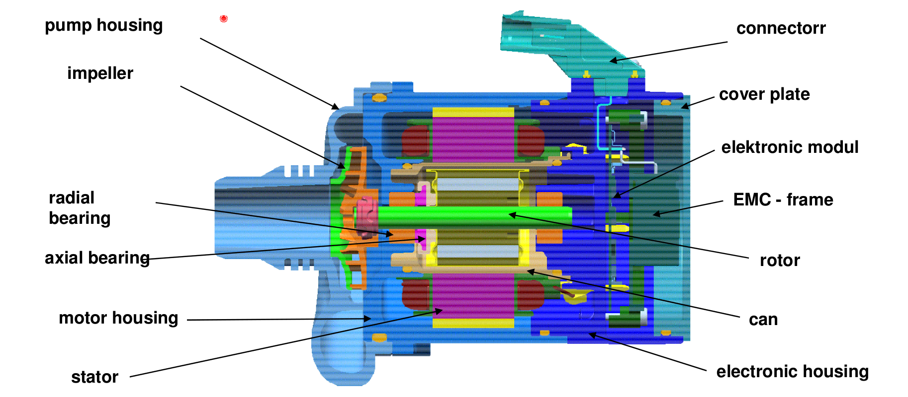
CWA50 Cutaway
Above is a cutaway drawing of the new pump. These have a drilling through the shaft allows water to pass from the high pressure outlet fitting, through the internals of the pump & returns through the shaft to the inlet. This keeps the bearings cool & lubricated. The control & power drive circuitry for the 3-phase brushless motor is attached to the back & uses the water flowing through the rotor chamber as a heatsink. Overall these are very well made pumps.
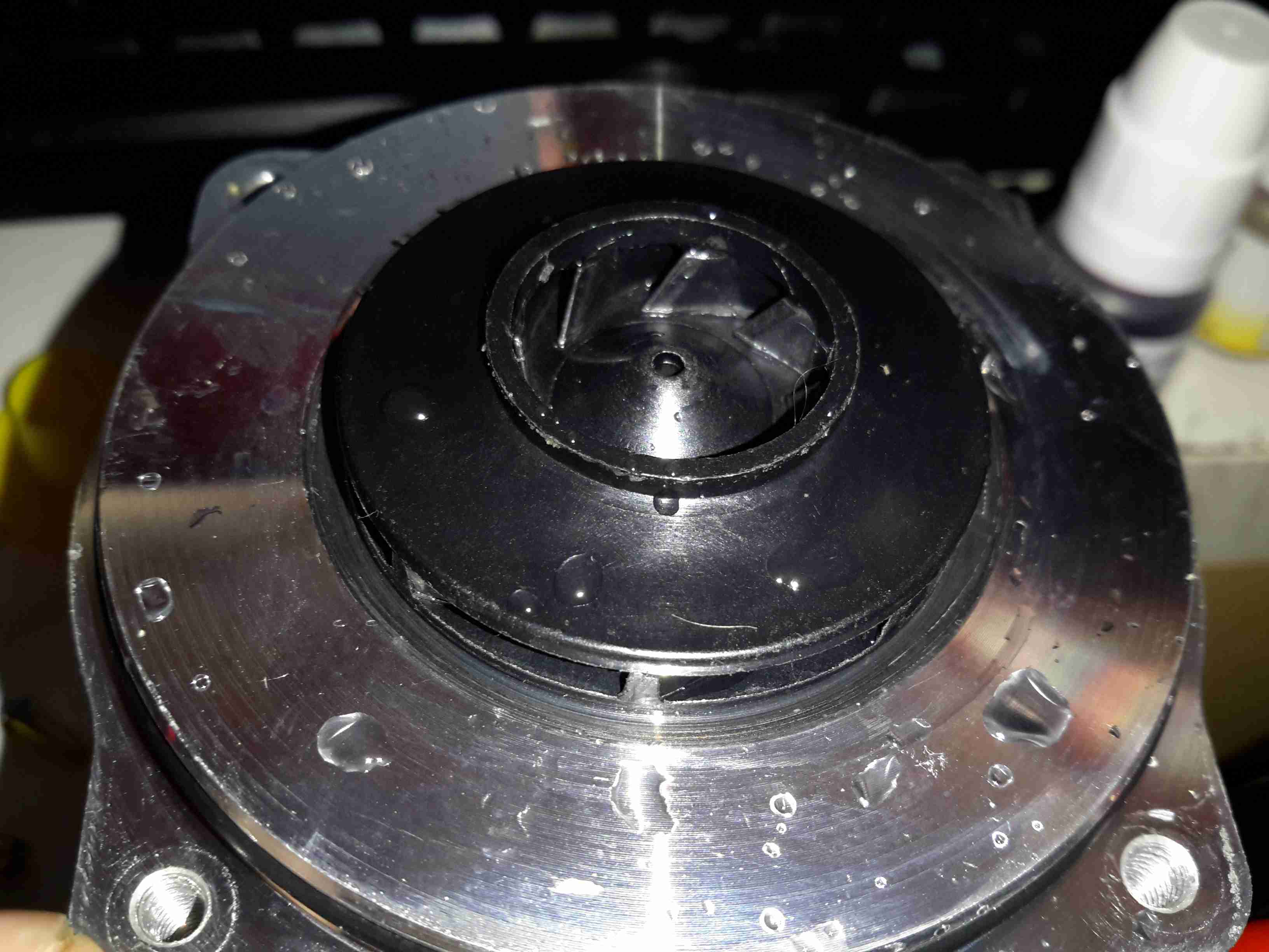
Impeller
Here’s the impeller of the pump, which is very small considering the amount of power this unit has. The return port for the lubricating water can be seen in the centre of the impeller face.
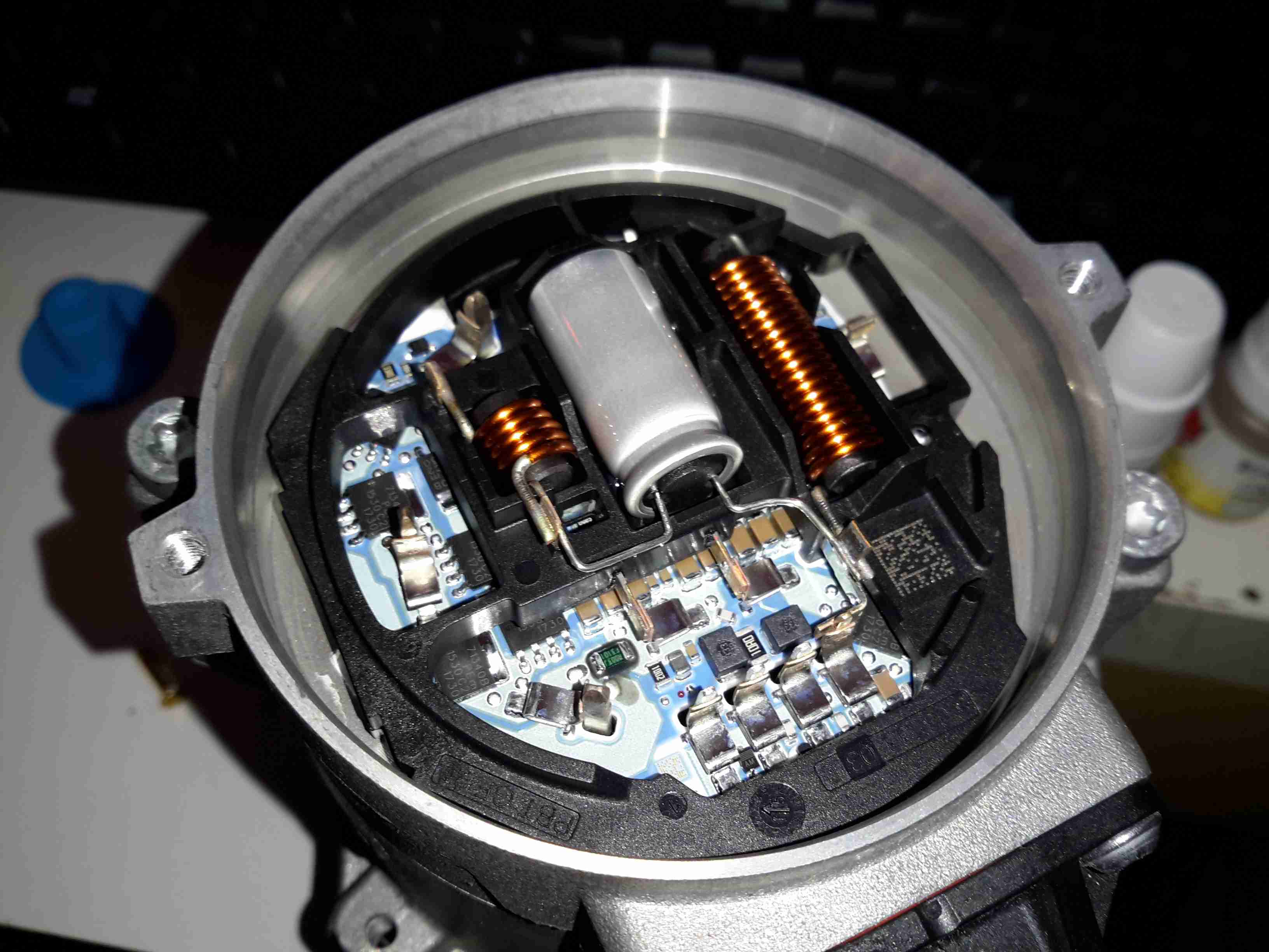
3-Phase Driver
Inside the back of the pump is the control module. The main microcontroller is hiding under the plastic frame which holds the large power chokes & the main filter electrolytic.
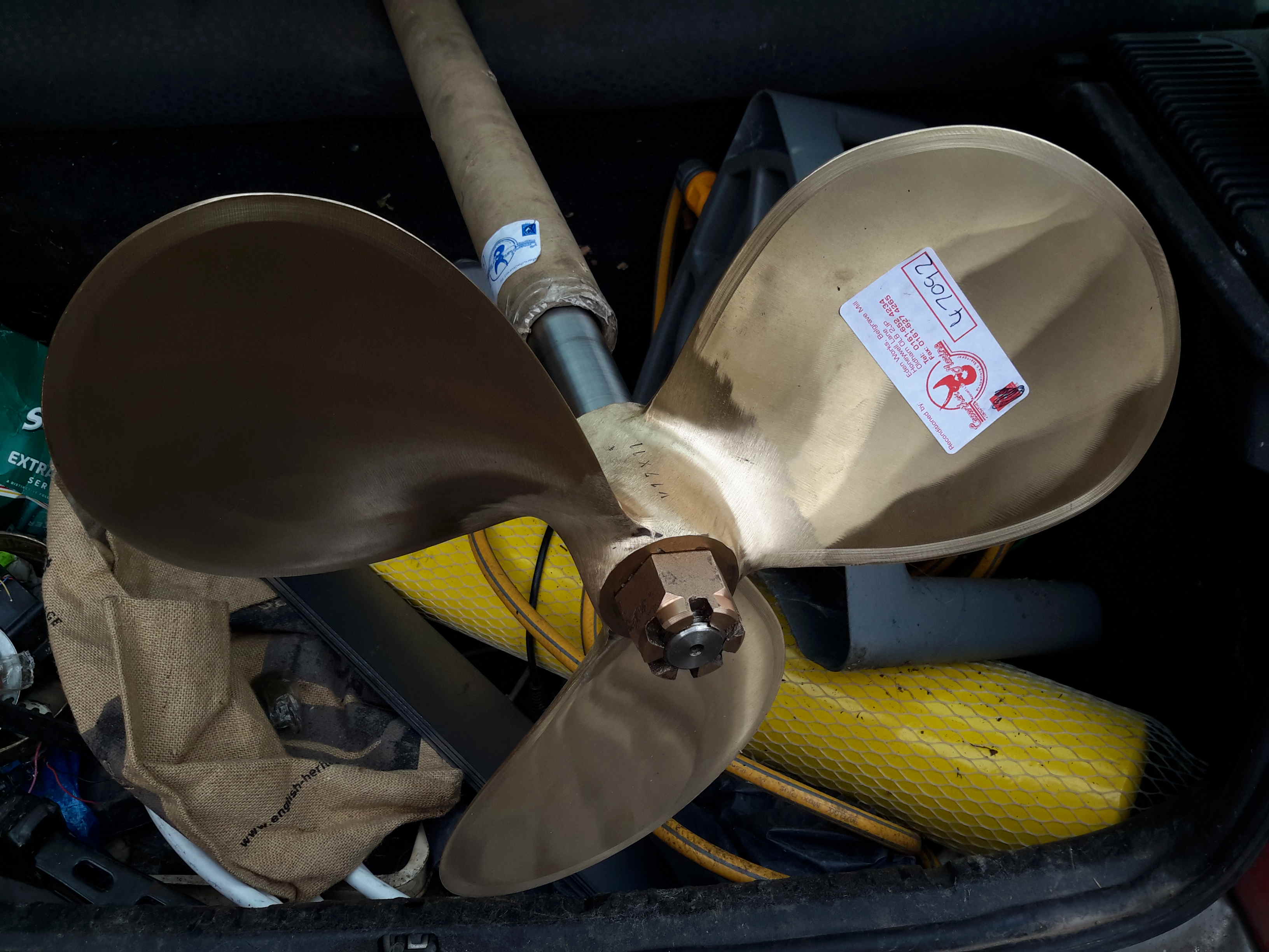
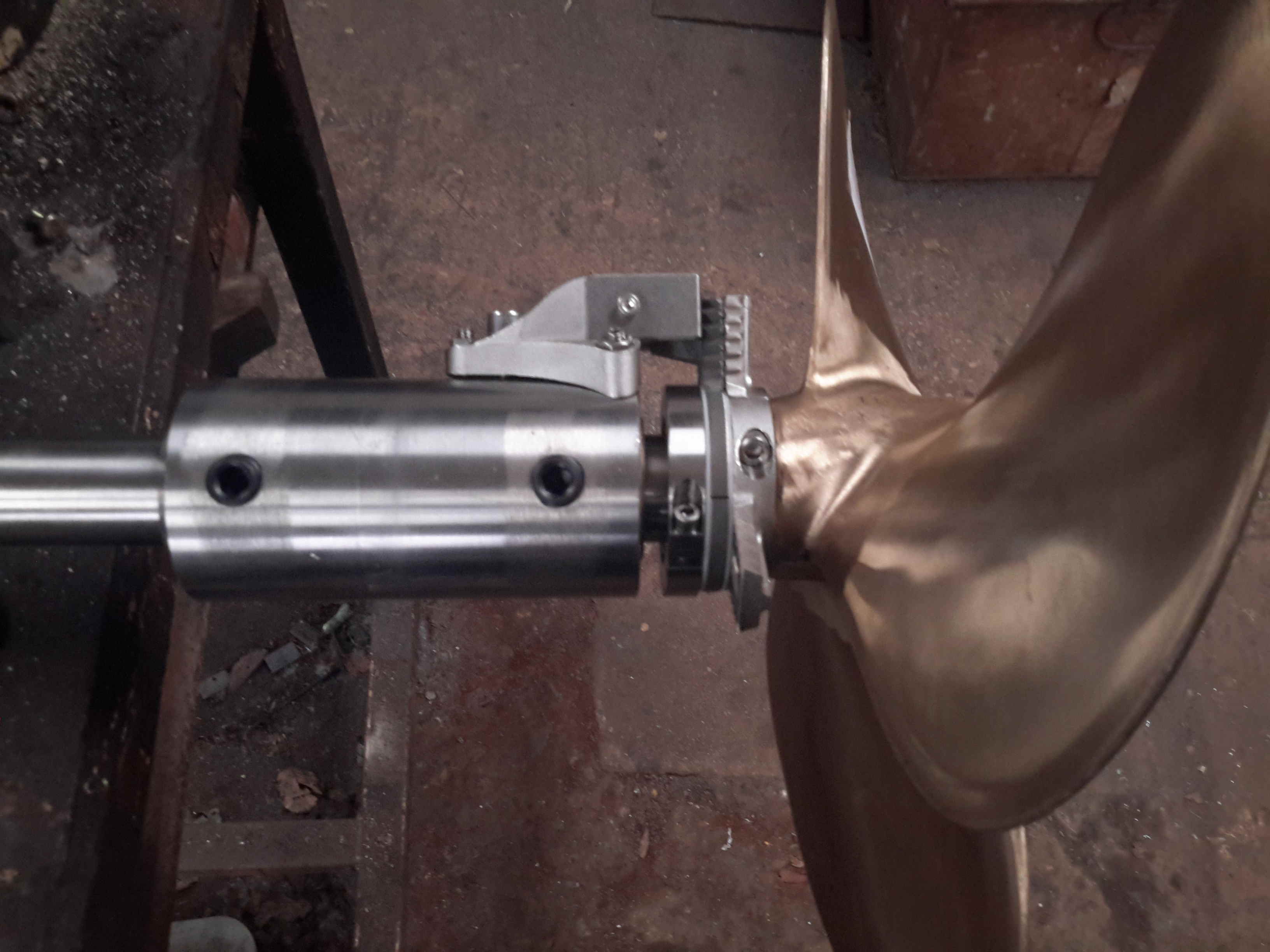
We’re now on the final leg of the jobs to be done on the boat! Above is the new prop & shaft, supplied to us by Crowther Marine over in Royton. To fit our current stern tube & gland, the shaft is the same diamter at 1-3/8″. Unfortunately no 4-blade props were available, so I had to go for a 17×11 left-hand, but with a much larger blade area than the old one.
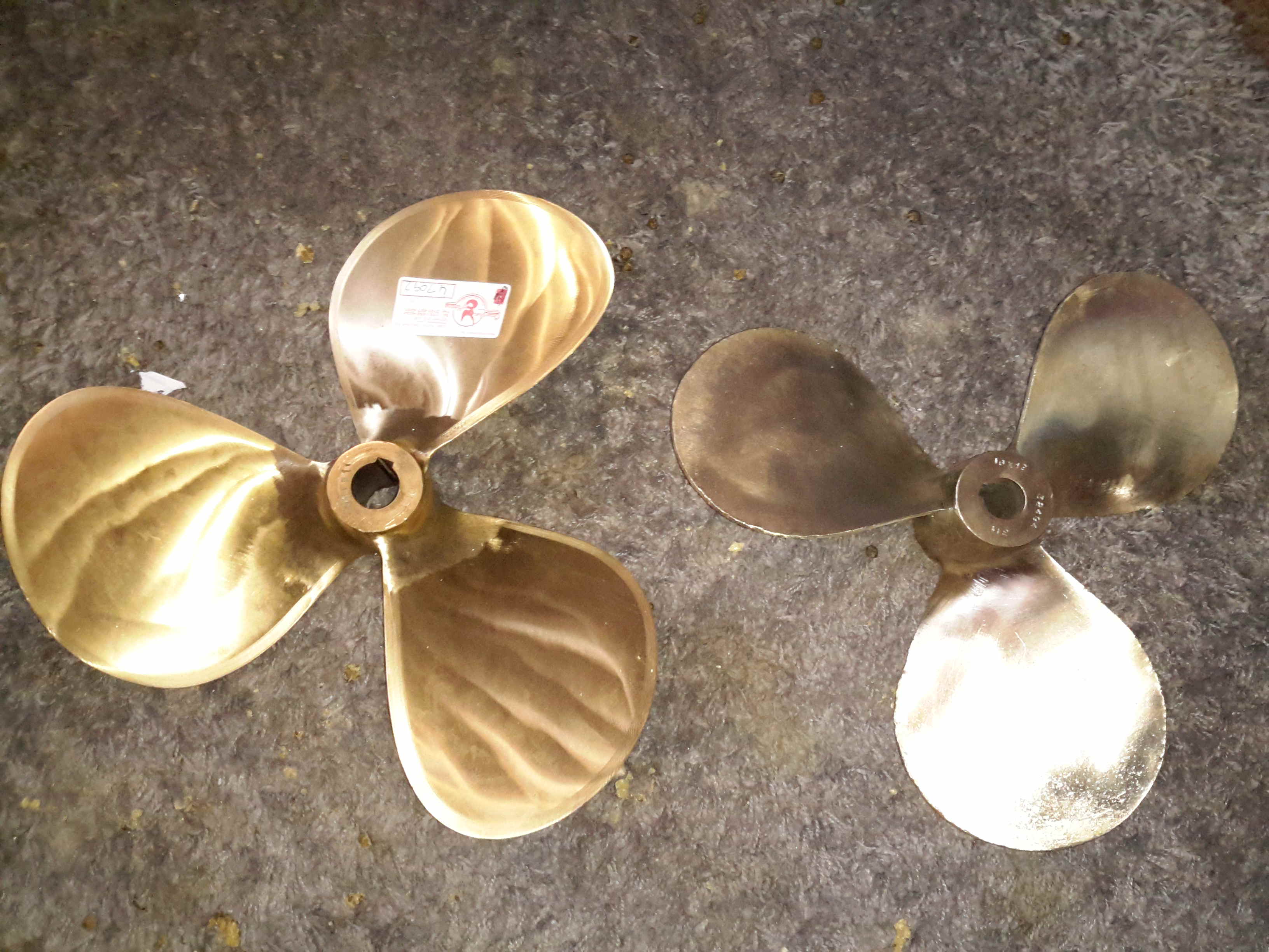
Propellers
Here’s the old prop on the right, with the new one on the left, amazing how different 1 inch of diameter actually looks. The opposite hand of the new prop makes no difference in our case, as I can simply switch the hoses to the hydraulic motor on the shaft to make everything reverse direction.
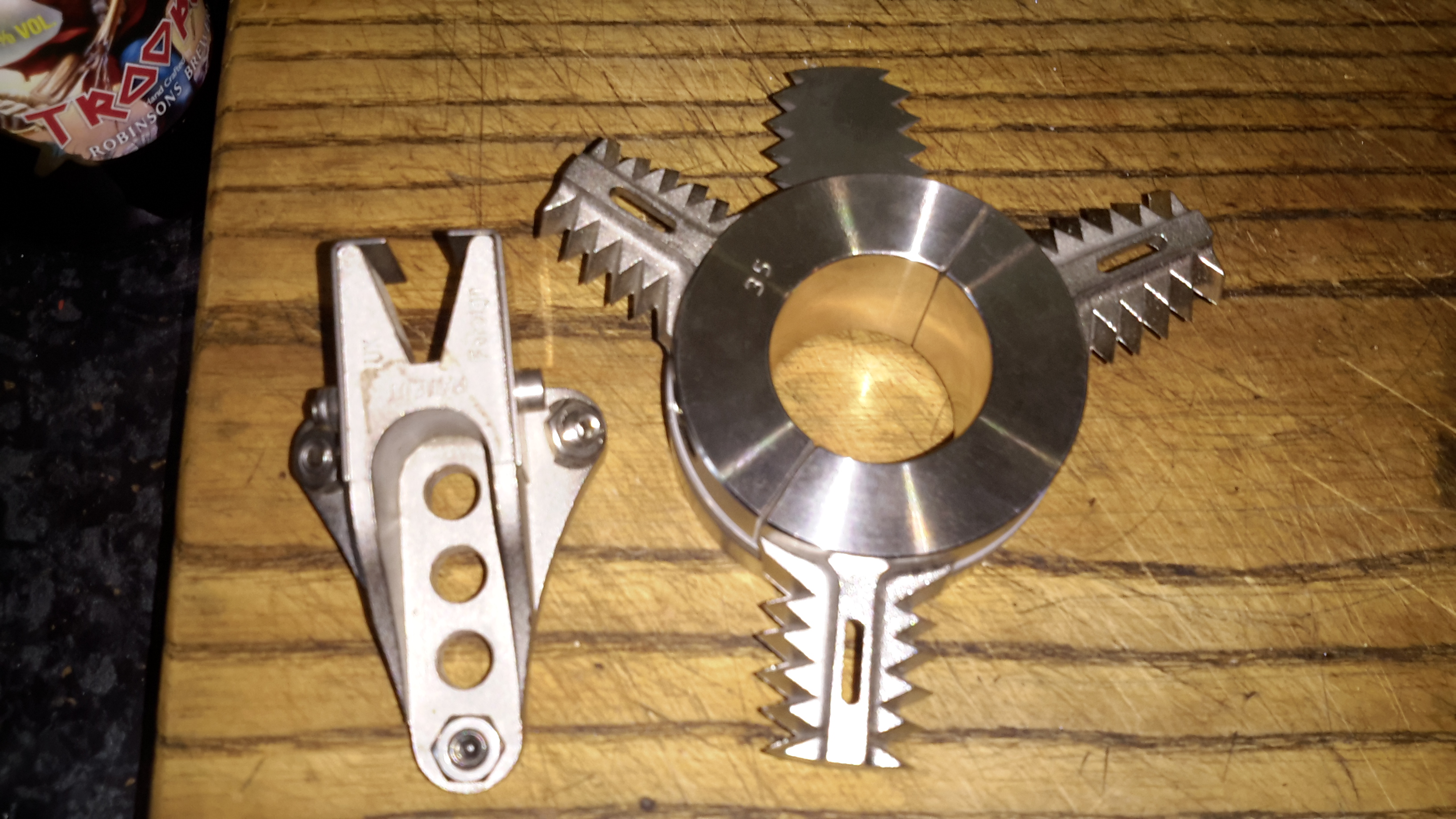
Stripper
Above is the solution to my problem of no weed hatch – a Stripper Rope Cutter from Ambassador Marine. This device has some seriously viciously sharp cutting teeth to help clear any fouling from the prop in operation. Only time will tell if it’s effective at allowing me to stay out of the canal manually removing the crap!
Cutless Bearing
We finally got the bearing mount finished, by S Brown Engineering in Stockport. This is made from Stainless steel to stop the bearing corroding in place & becoming a real arse to replace. Set screws are fitted to make sure the bearing doesn’t move in service.
Attached to the side of the bearing housing is the fixed blade mounting for the Stripper Rope Cutter.
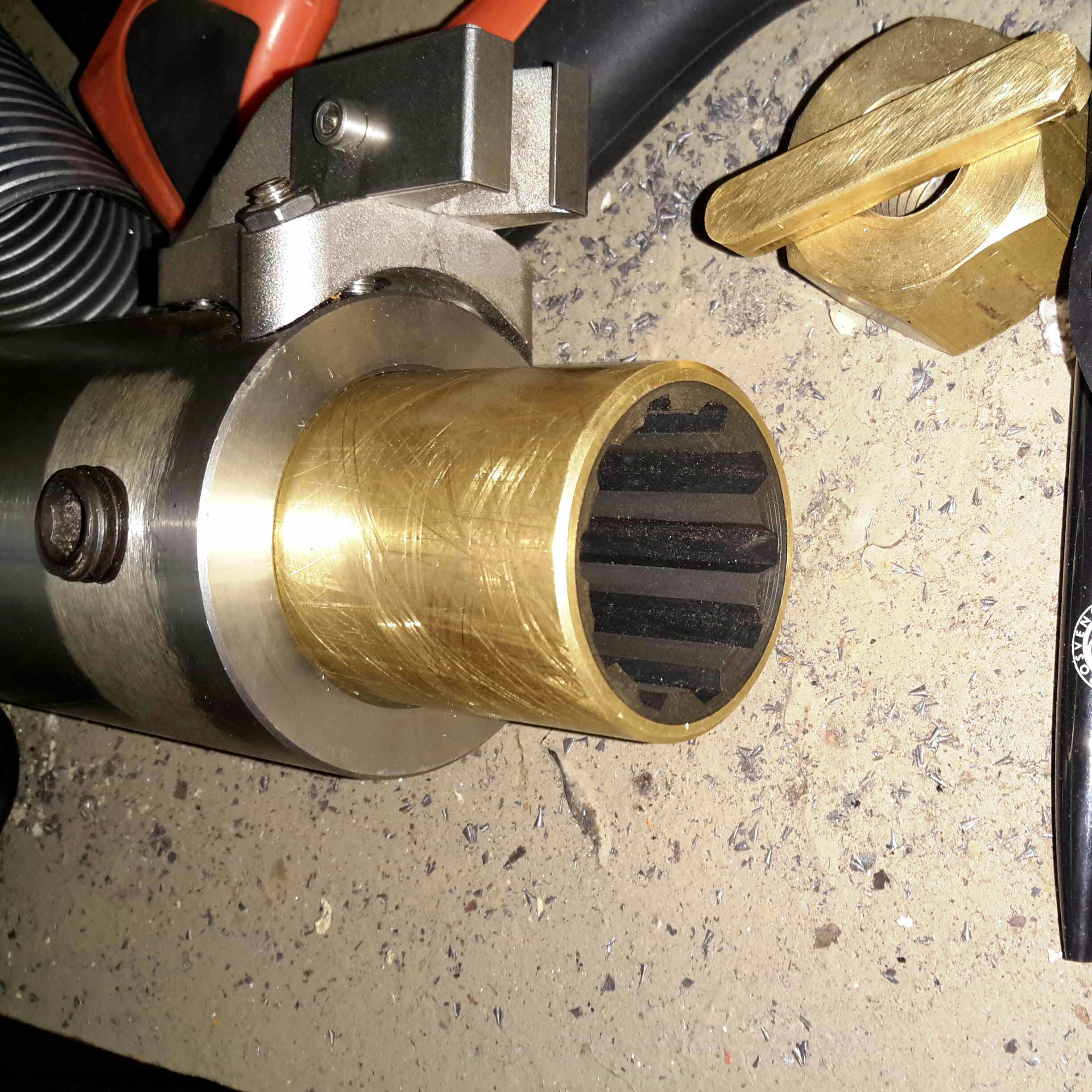
Bearing Test Fit
Above is everything fitted to the shaft for a test before the gear went into it’s home in the stern tube. The Stripper mounts behind the prop, clamped to the shaft. The 3 moving blades move against the fixed blade like a mechanised pair of scissors.
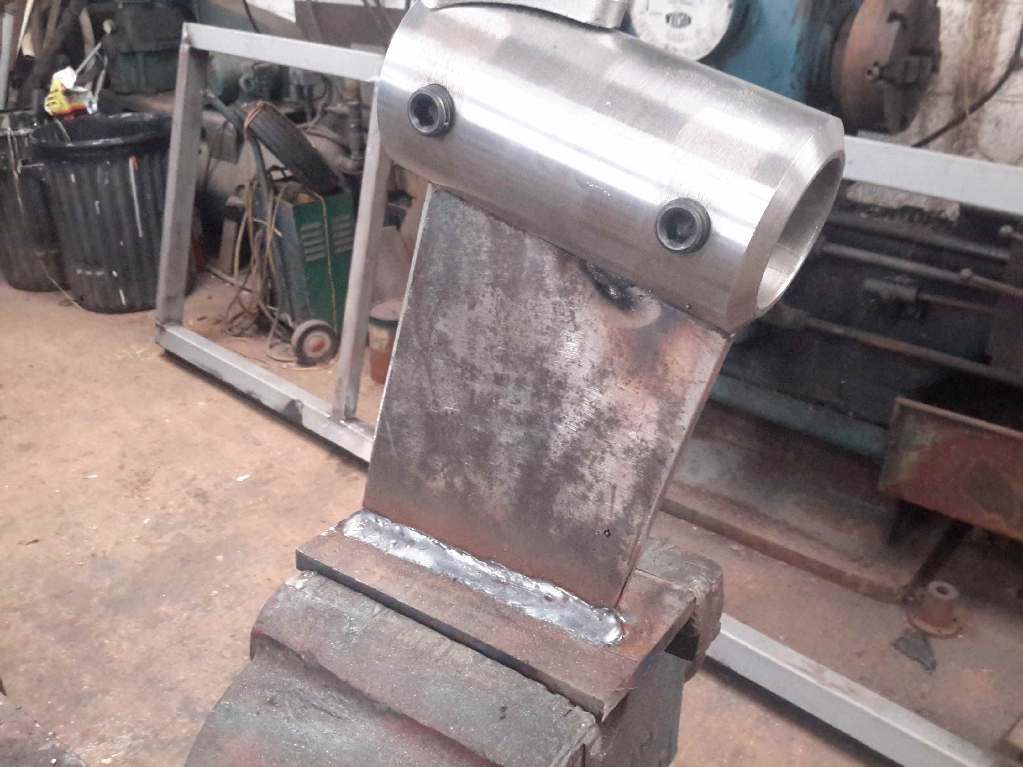
Bearing Strut Welding
10mm steel plate has been used to make the strut for the bearing tube, welded together. In the case of the joint between the stainless tube & the carbon steel strut, special welding rods were needed, at the price of £2 a rod! Using mild steel rods to weld stainless could result in cracking of the welds. Not a good thing on a prop shaft support bearing.
Sand Blasted Hull
Most of the old tube has been cut away to make room for the new bearings, and the bottom of the hull has been sand-blasted ready for welding.
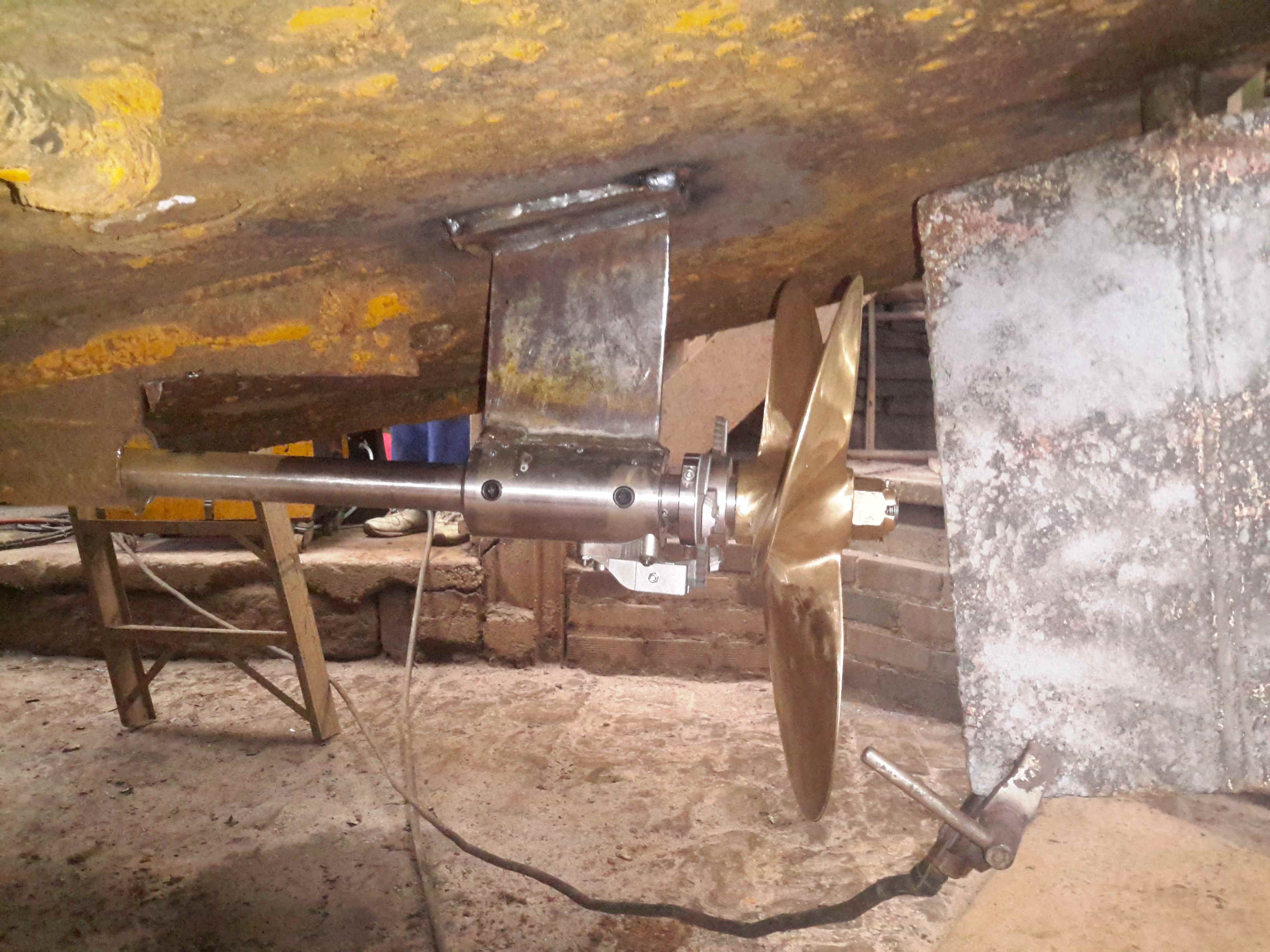
Running Gear Mounted
The bearing mount is welded to the hull, the Stripper & the prop are fitted to the end of the shaft. There’s 1.5″ of clearance from the blade tips to the hull plating. The rudder has about an inch of clearance to the end of the shaft.
Rudder Fence
To help keep the prop wash down, directing more of the force into moving the vessel rather than creating a nice rooster tail, a pair of plates has been welded onto the rudder. These also provide a handy step should someone fall in ;).
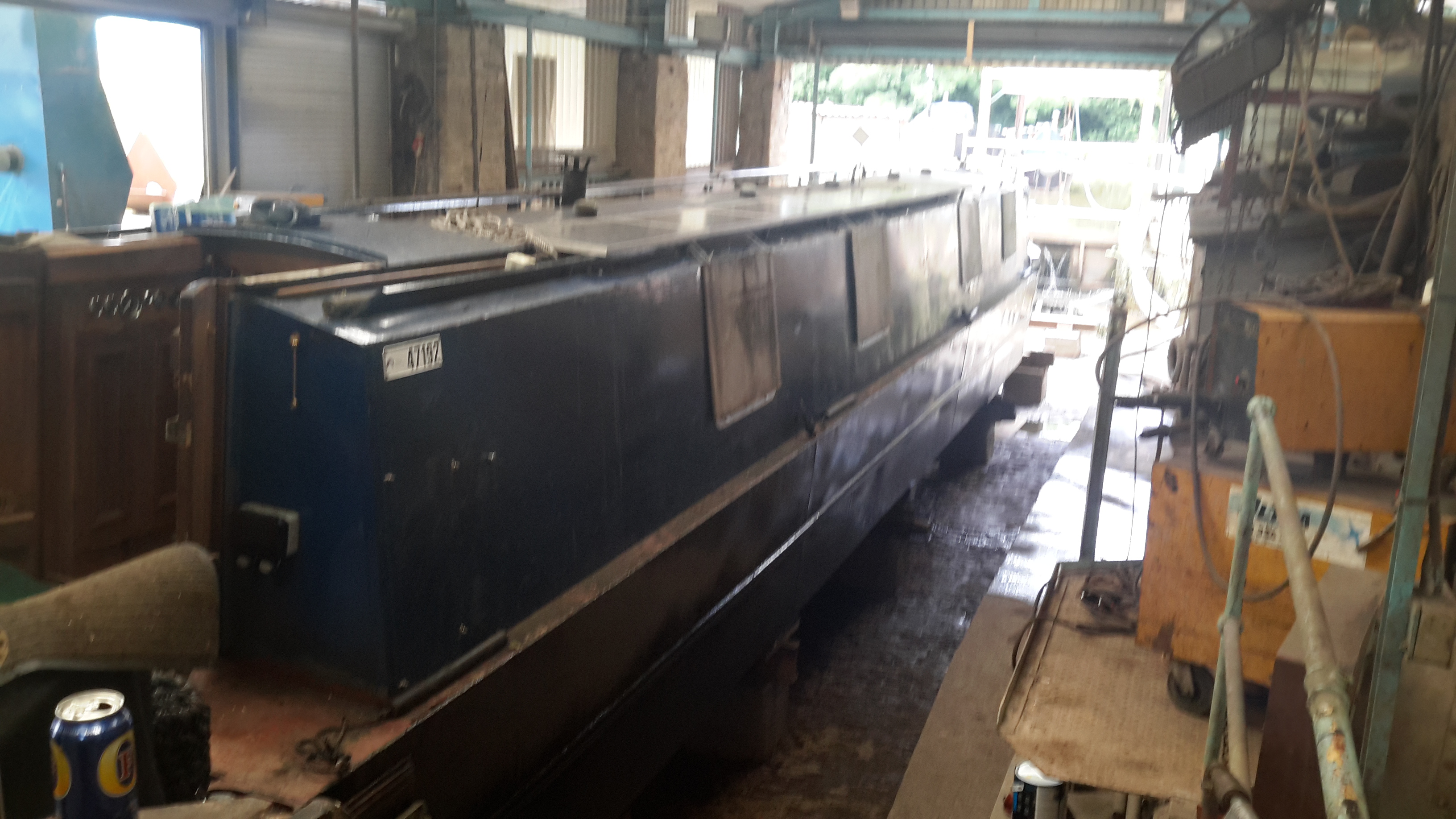
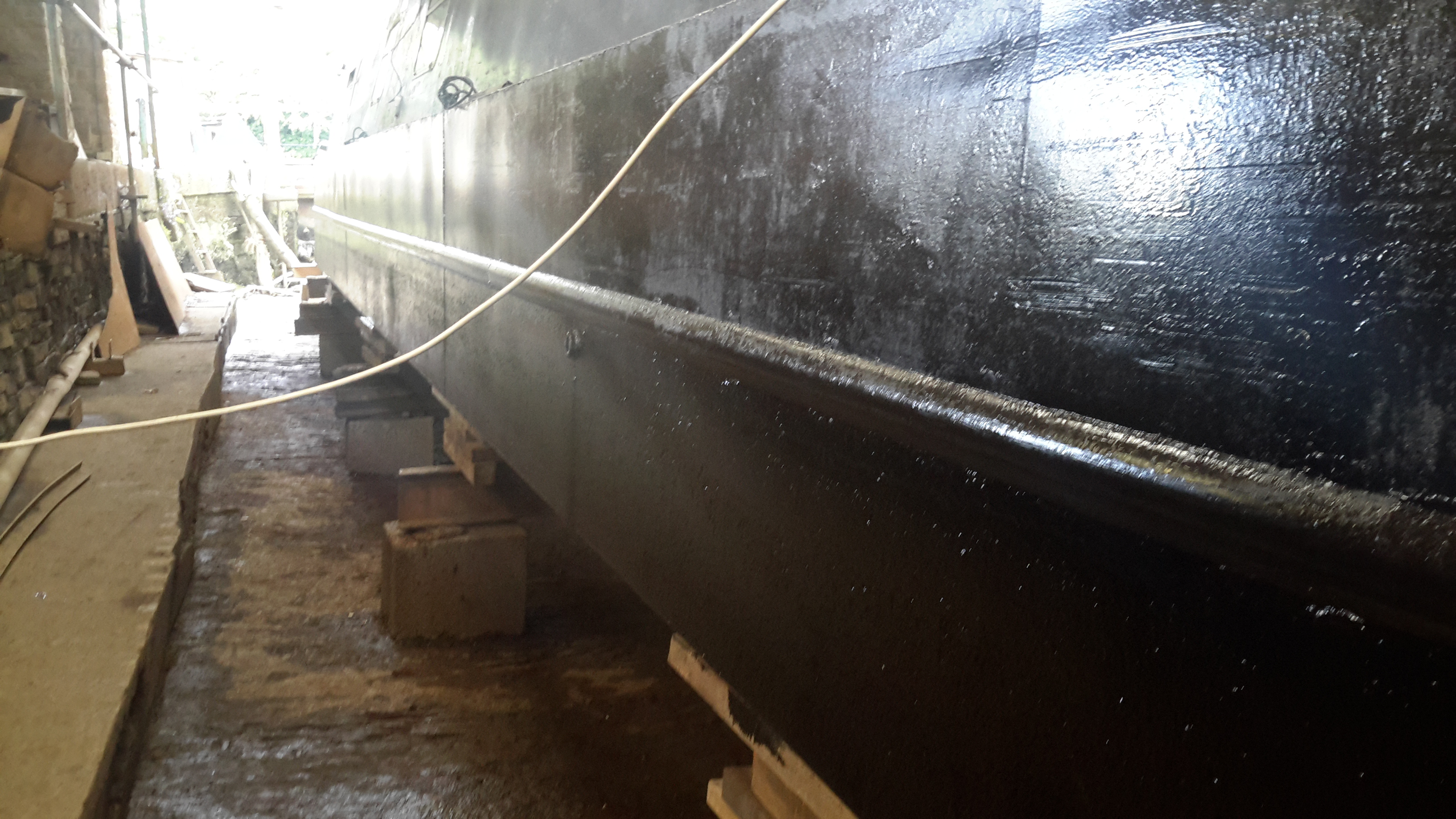
Things are coming along nicely with this year’s drydock operations.
Blacking – Second Coat
Shes looking much better, the second coat of bitumen blacking is on, we’re going to continue at a coat a day until we’re due back in the water.
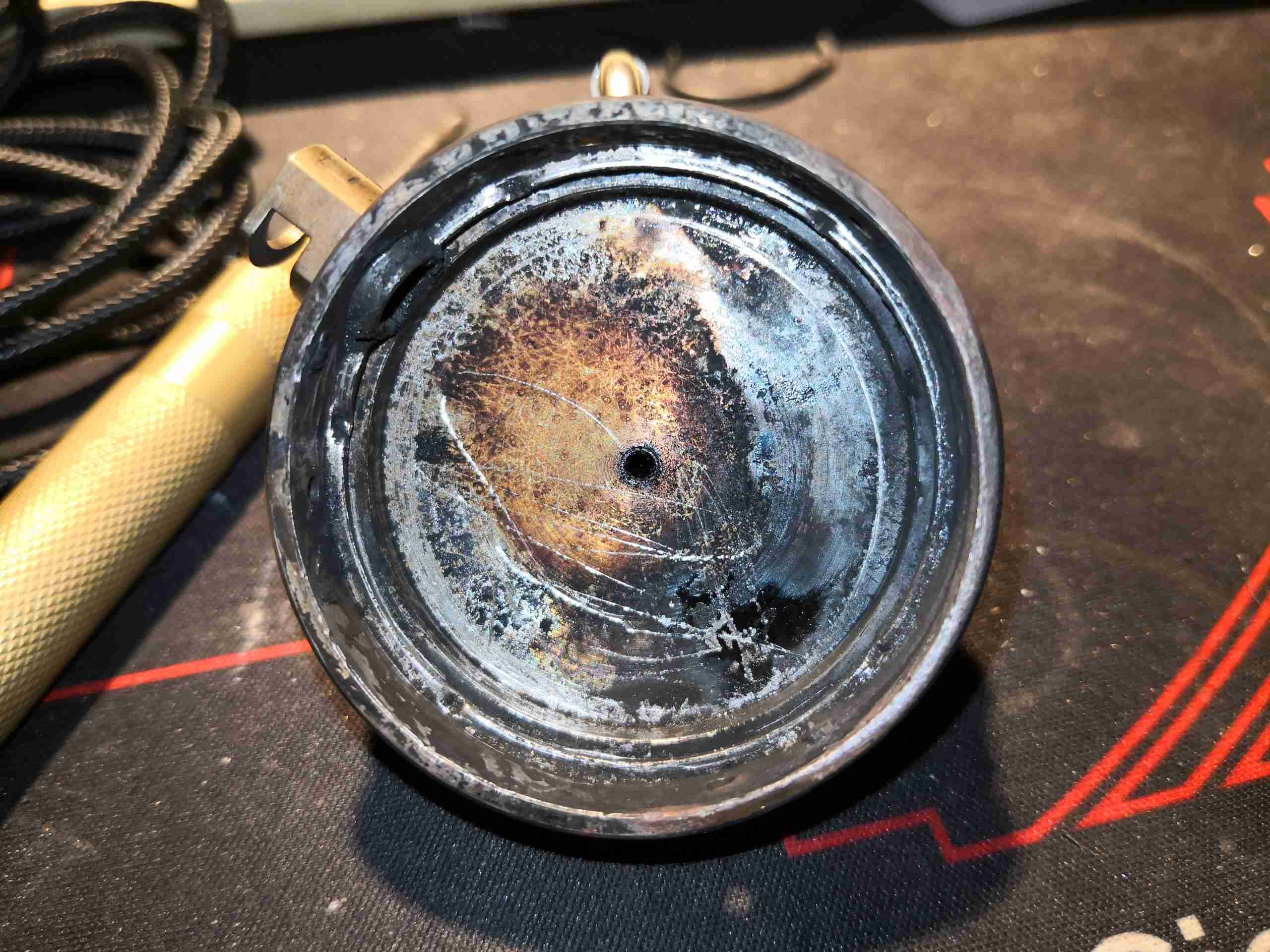
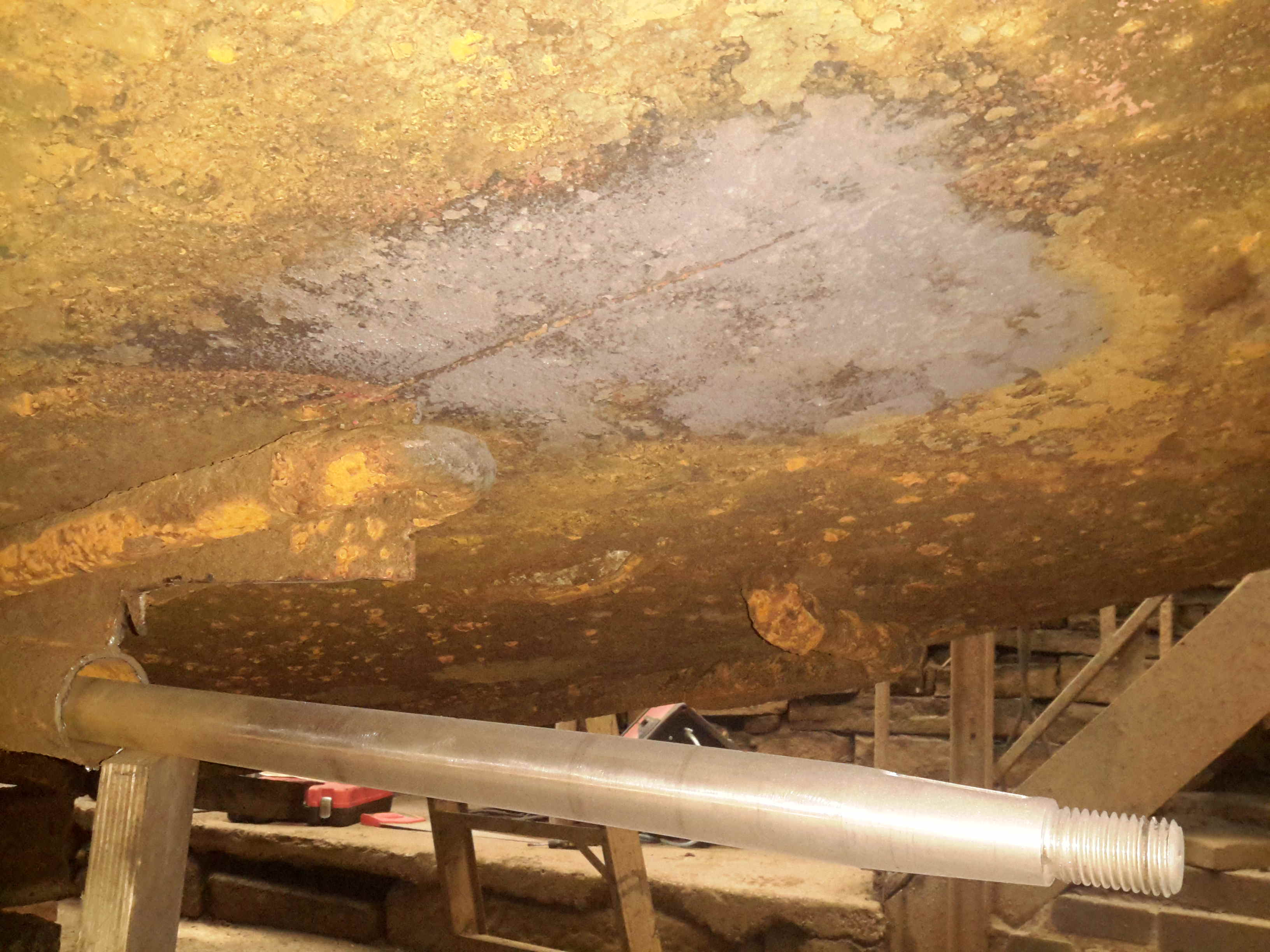
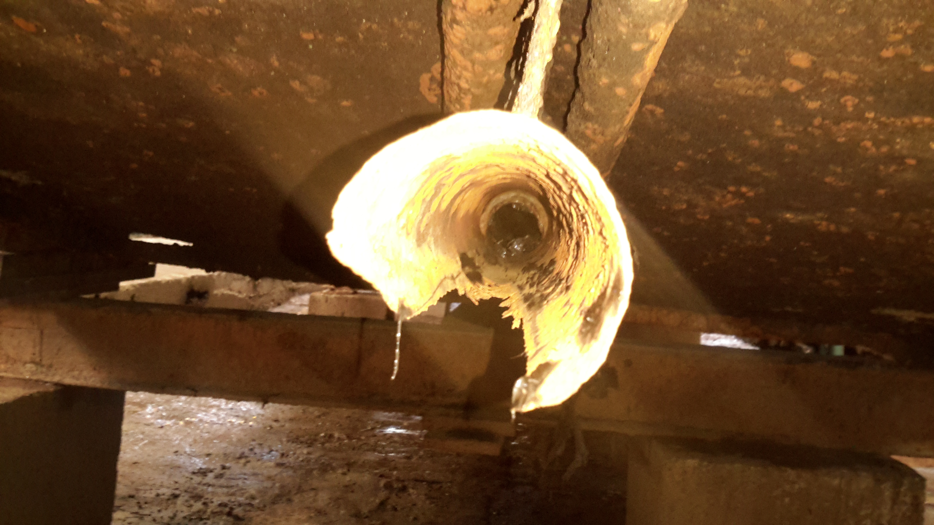
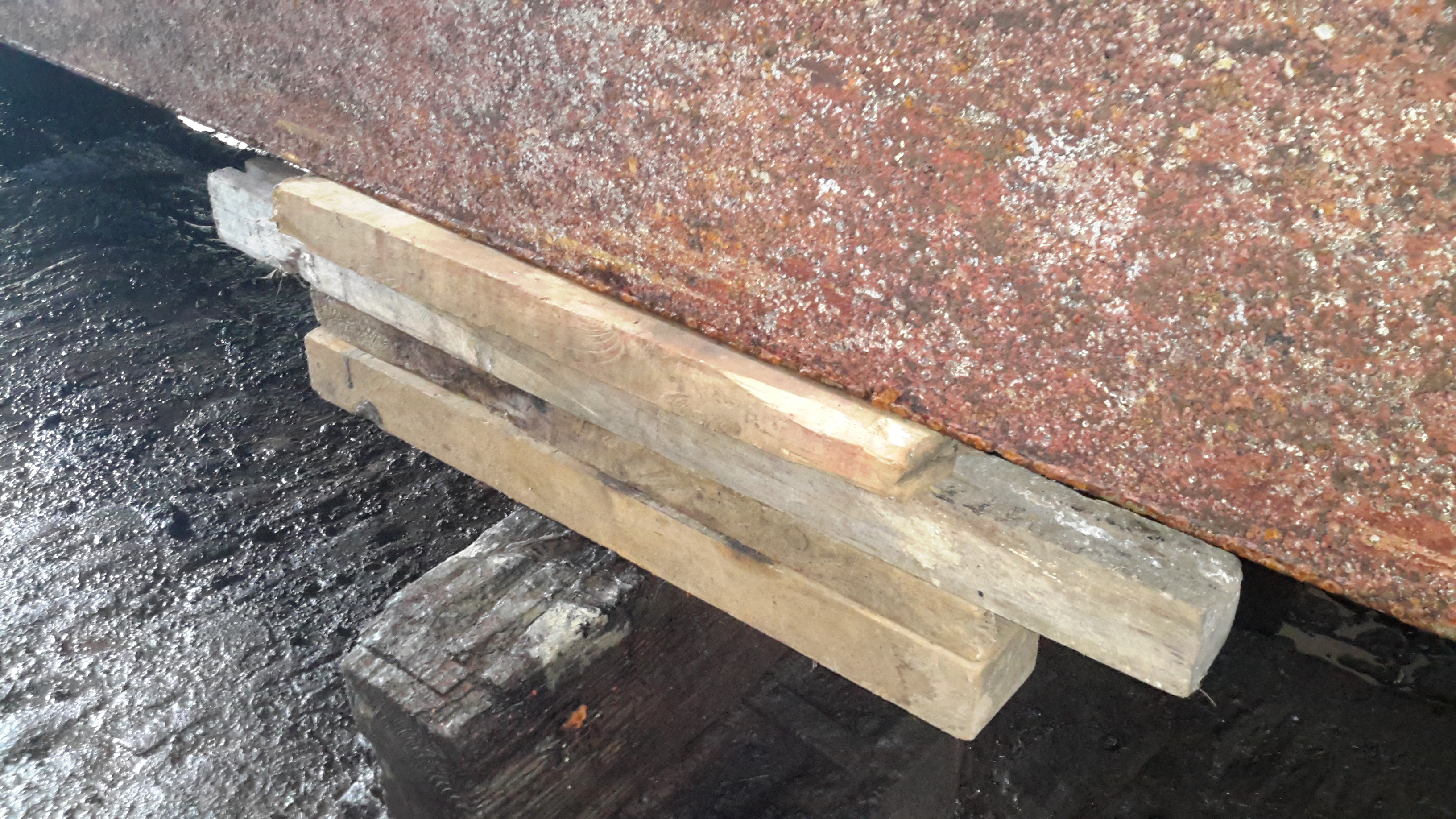
Shaft Tube Damage
I’ve now removed the shaft from the stern tube to gain better access, now the full extent of the damage to the tube can be seen. There’s nothing left at all of the old bearing, which on this boat was simply a nylon bushing pressed into the end of the tube. (I knew it was crap the last time we were out, but ran out of time to get a fix done).
The stainless shaft, having lost it’s support bearing at some point, has been running on the inside of the steel tube, and has neatly chewed straight through it.
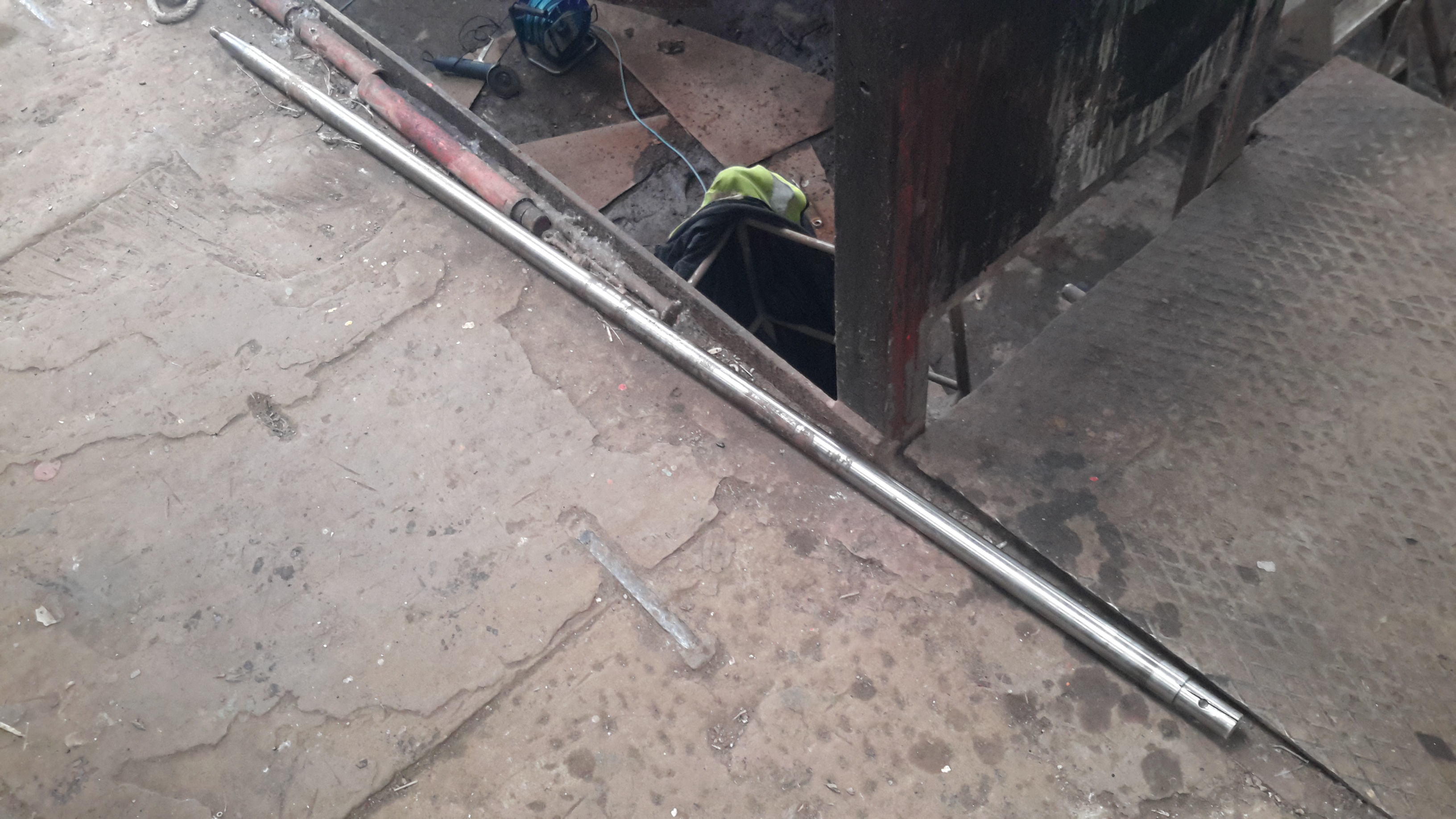
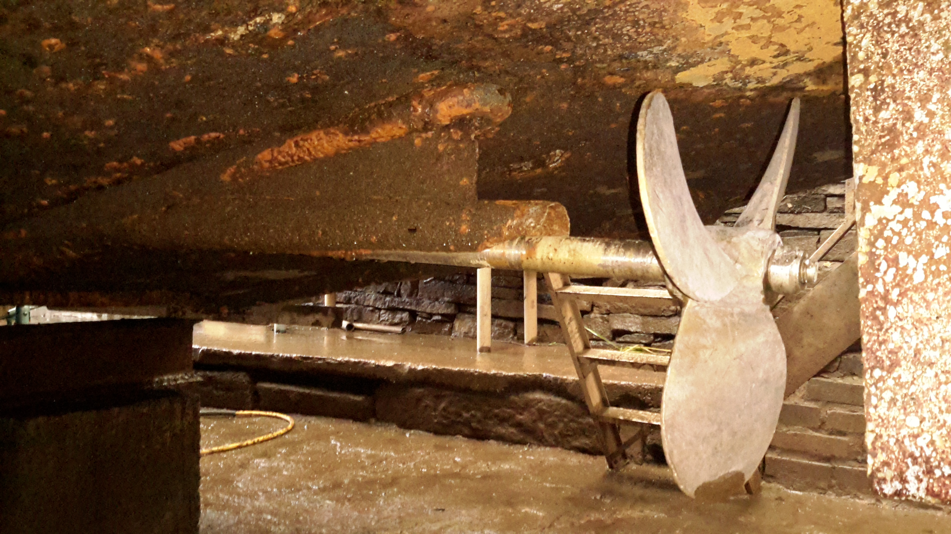
Prop Shaft
Here’s the prop shaft removed from the boat – possibly the longest shaft I’ve ever seen on a narrowboat at 6′ 2″. Unfortunately, the fact that it lost the bearing has also damaged the shaft itself, this will have to be replaced.
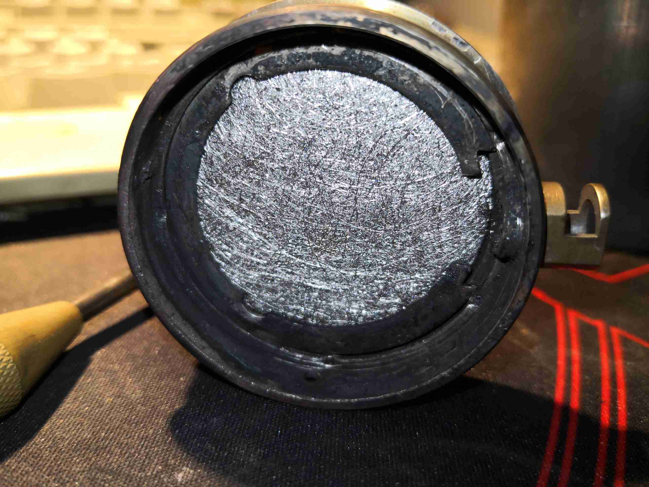
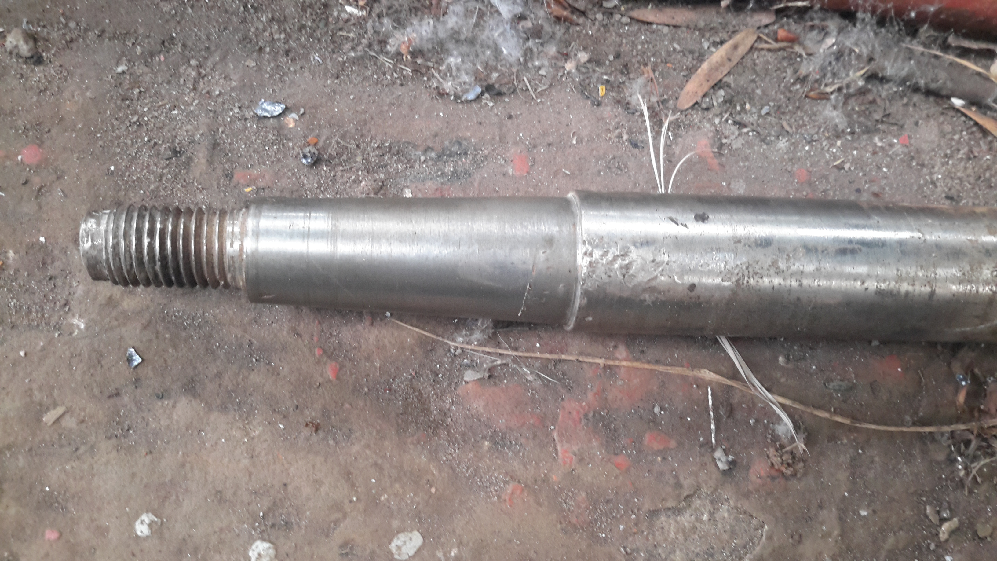
Prop Taper
Here’s the end of the shaft that would run in the end bearing, it’s badly scored & fitting a new bearing to this shaft would cause failure very quickly. The taper on the end isn’t much better, and a loose fit in the prop has done some damage there also.
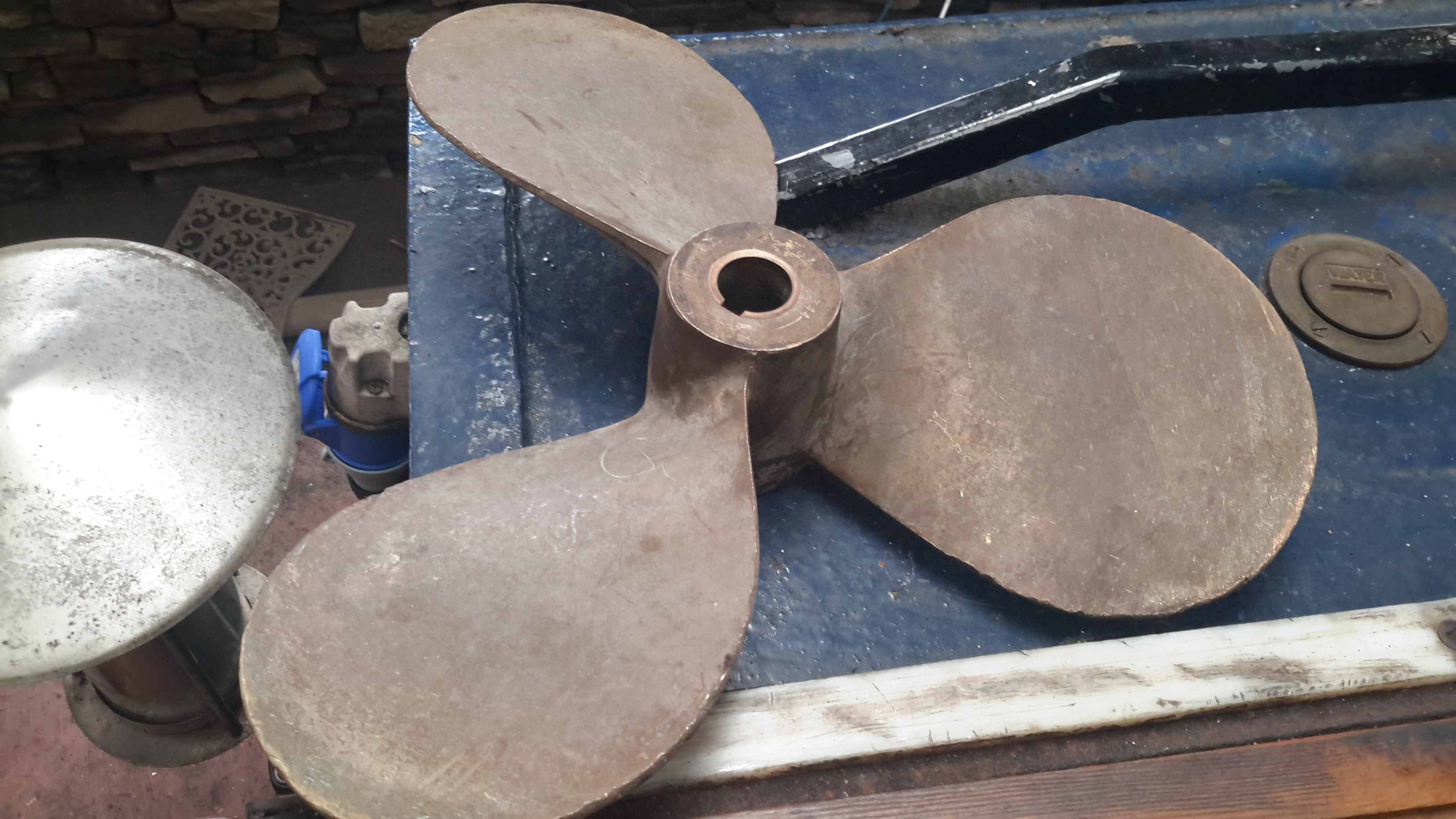
Old Prop
Here’s the old prop – a 16×12 that was only fitted a few years ago. This will be replaced with a new 4-blade prop, as this one is far too small for the size of the boat & installed power. Installing a larger diameter prop isn’t possible due to clearance from the swim, so I’ll have to get a more steeply pitched prop, with 4-blades for increased contact area with the water.
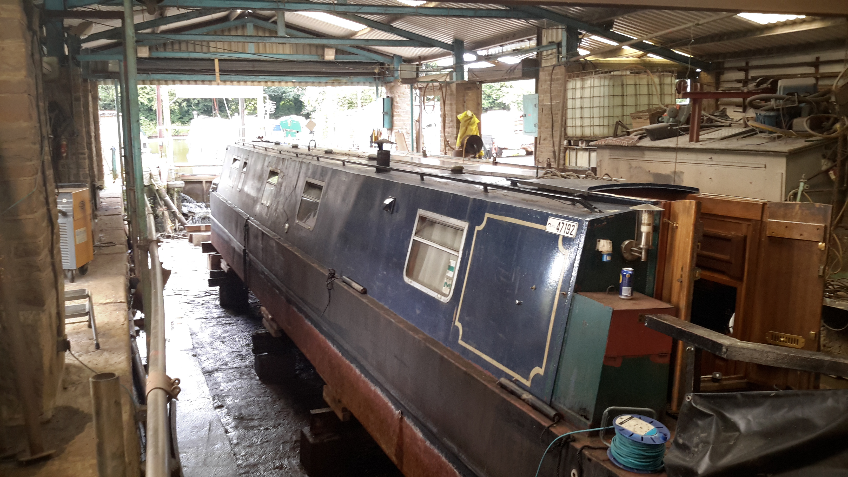
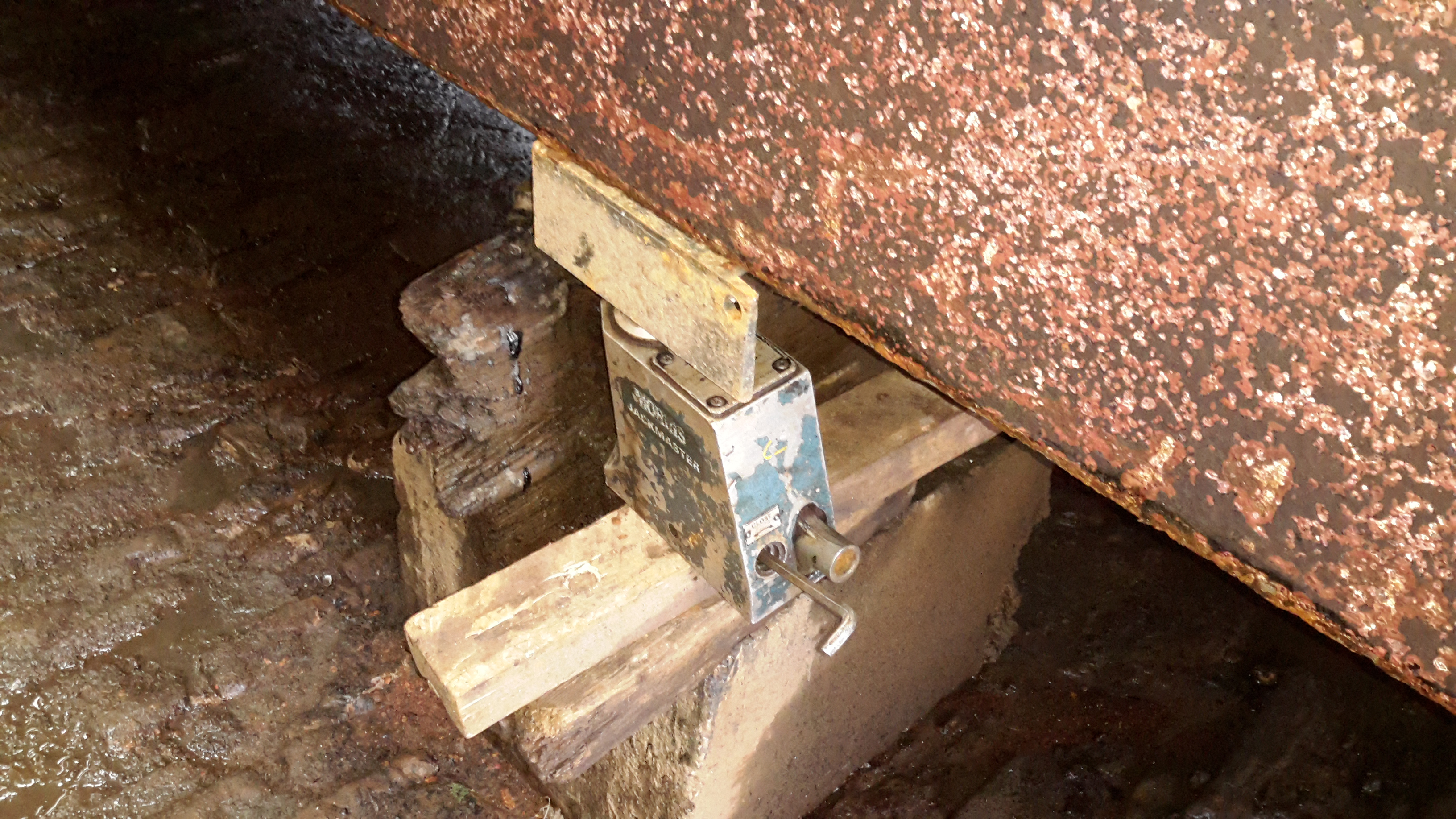
It’s that time again, so the boat is out of the water for it’s 3-yearly maintenance. Some things over the past few months have been bugging me, namely a pronounced vibration in the running gear while underway. (Issue was easy to spot here!).
10-Ton Jack
nb Tanya Louise being a very odd vessel, she has quite a significant keel, so once the dock was drained, some manual jacking was required to get her level on the blocks. Without this extra work there is such a pronounced heel that it’s impossible to do anything on board.
Chocks
On the opposite side, wooded blocks are placed for the bottom of the hull to rest against. Jacking up a 58-ft 25-ton boat by hand onto some timbers was nerve-wracking to say the very least!
The bottom of the hull has already been jet-washed to remove 3-year’s worth of slime, weed growth & the old blacking. First job is to get a fresh coat of paint on.
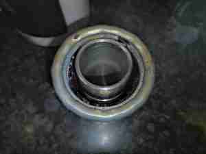
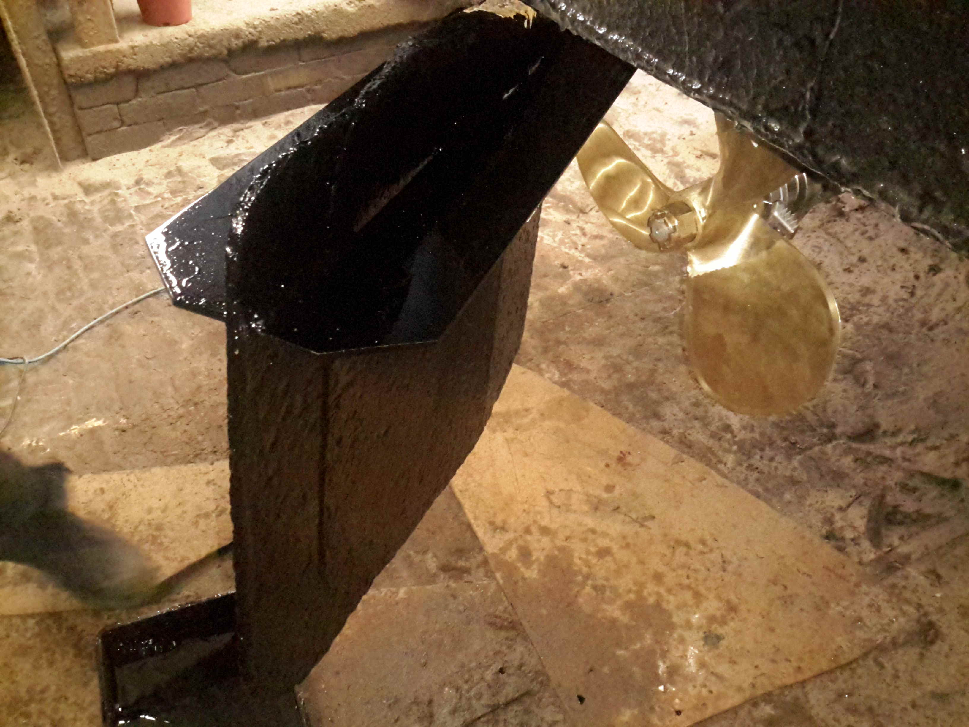
Running Gear
Looking under the hull shows the reason for the high level of vibration – the prop shaft has actually *worn through* the bearing & stern tube, to the extent that there’s not much left of the assembly! The only thing holding the shaft in place at this stage is the stuffing box inside the boat & the shaft coupling to the hydraulic motor.
, stern tube,
A replacement standard-issue Cutless bearing will be fitted, after the remains of the old tube are cut back to make room. To facilitate mounting the bearing, a custom stainless P bracket is being made at a local engineers, for me to weld onto the bottom of the hull.
(Surprised we didn’t lose the shaft, lucky that I kept pestering to get her out of the water!).
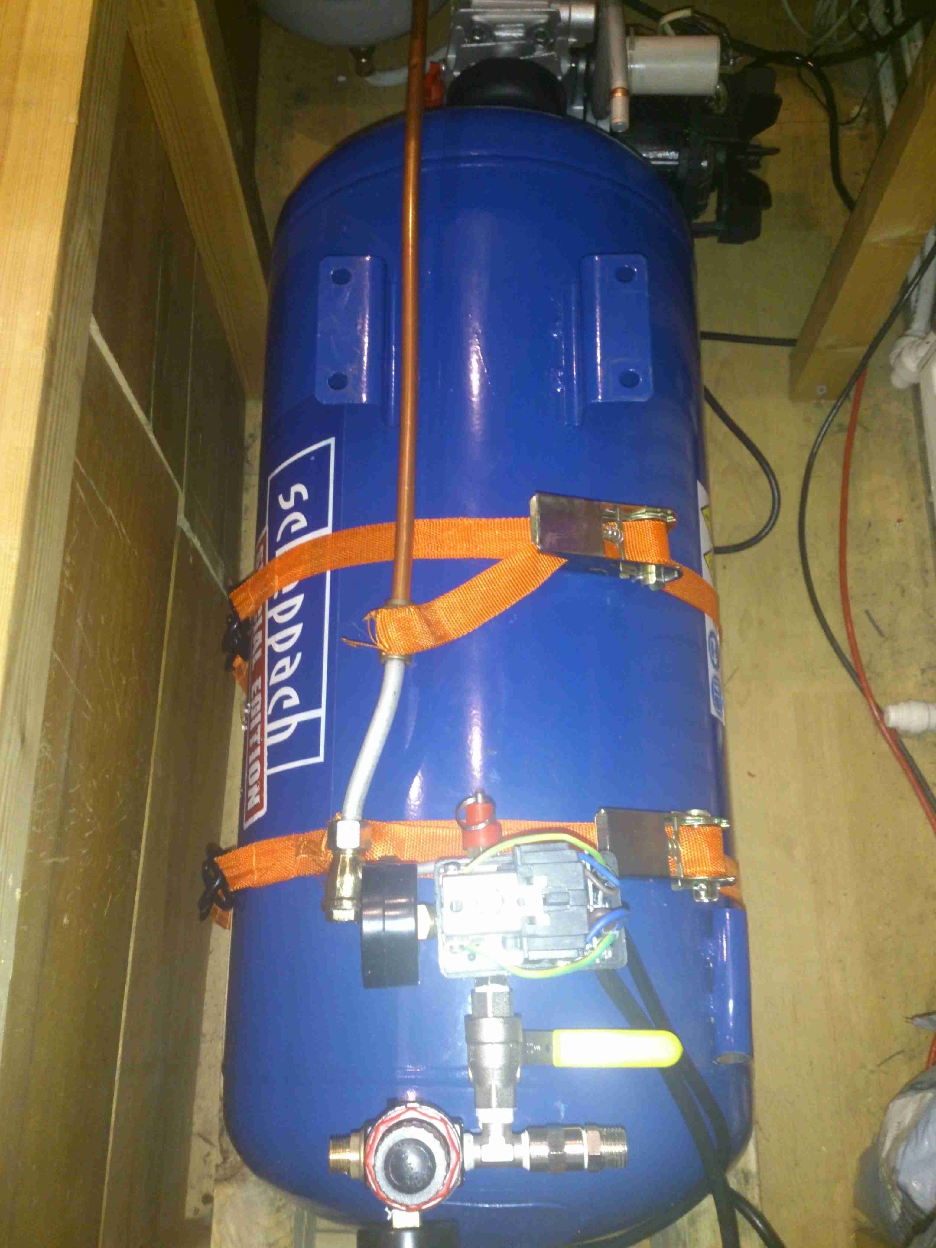
Compressed air is a rather useful power source, especially when all maintenance is done by the on board crew instead of by boatyards.
Screwfix had a good deal on a 50L 3.5CFM air compressor, to save space this has been permanently mounted in a free space & air will be piped to where it is needed from a central point.
Because of the total height of the machine, the compressor itself has been unbolted from the tank, a copper line connecting the two back together at a larger distance.
Bearers
In one of the very few free spaces available, under a bunk. A pair of timbers has been screwed to the floor to support the tank.
Tank Installed
The tank is strapped to the wooden supports with a pair of ratchet straps, the compressor itself can be seen just behind the tank. The copper line on the top of the tank is going back to be connected to the compressor outlet.
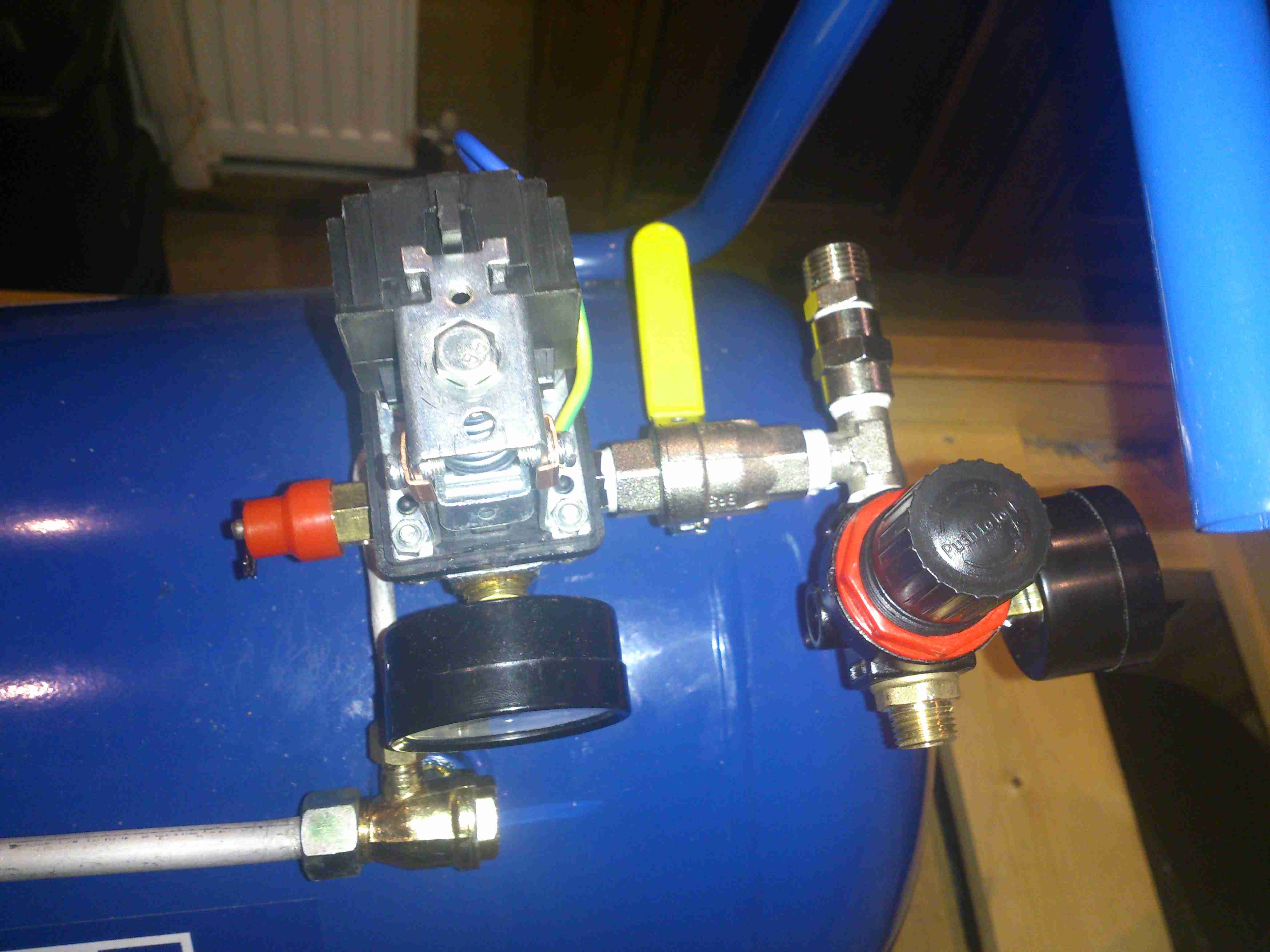
Air Fittings
Compressor control remains on top of the tank, the pressure switch & relief valve centre. After an isolation valve, the feed splits, the regulator installed will be feeding the air horn with 20PSI, replacing the existing automotive-style 12v air pump. The currently open fitting will be routed to a quick connect on the bulkhead. This will be accessible from the front deck, an air hose can be fitted to get a supply anywhere on board.
More to come when the rest of the system gets installed!
73s for now.
Tip Jar
If you’ve found my content useful, please consider leaving a donation by clicking the Tip Jar below!
All collected funds go towards new content & the costs of keeping the server online.