Posted on 8 Comments

Sterling ProCharge Ultra PCU1210 Teardown & Repair

The Sterling charger we’ve had on board nb Tanya Louise since Feb 2014 has bitten the dust, with 31220 hours on it’s internal clock. Since we’re a liveaboard boat, this charger has had a lot of use while we’re on the mooring during winter, when the solar bank isn’t outputting it’s full rate. First, a bit of a teardown to explore the unit, then onto the repair:
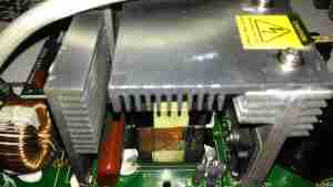

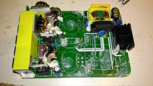
Active PFC Section
Active PFC Section

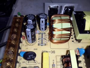
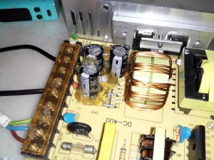
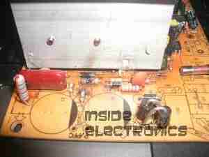
There’s the usual mains input filtering on the left, with the bridge rectifier on it’s heatsink.
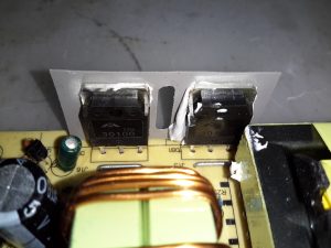
Underneath the centre massive heatsinks is the main transformer (not visible here) & active PFC circuit. The device peeking out from underneath is the huge inductor needed for PFC. It’s associated switching MOSFET is to the right.
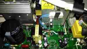
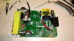
Logic PSU Section
Logic PSU Section

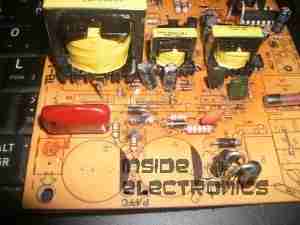
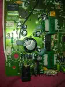
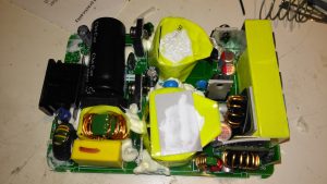
On the other side of the PFC section is the main DC rail filter electrolytic, a 450v 150µF part. Here some evidence of long-term heating can be seen in the adhesive around the base, it’s nearly completely turned black! It’s not a decent brand either, a Chinese CapXon.
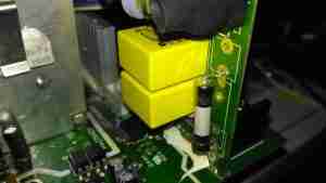
The PCB fuse just behind it is in the DC feed to the main switching supply, so the input fuse only protects the filter & Active PFC circuitry. Luckily this fuse didn’t blow during the failure, telling me the fault was earlier in the power chain.
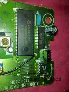
The logic circuits are powered by an independent switching supply in the centre, providing a +5v rail to the microcontroller. The fan header & control components are not populated in this 10A model, but I may end up retrofitting a fan anyway as this unit has always run a little too warm. The entire board is heavily conformal coated on both sides, to help with water resistance associated with being in a marine environment. This has worked well, as there isn’t a single trace of moisture anywhere, only dust from years of use.
There is some thermal protection for the main SMPS switching MOSFETS with the Klixon thermal fuse clipped to the heatsink.
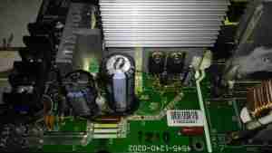
DC Output Section
DC Output Section

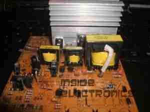
The DC output rectifiers are on the large heatsink in the centre, with a small bodge board fitted. Due to the heavy conformal coating on the board I can’t get the ID from this small 8-pin IC, but from the fact that the output rectifiers are in fact IRF1010E MOSFETS, rated at 84A a piece, this is an synchronous rectifier controller.
Oddly, the output filter electrolytics are a mix of Nichicon (nice), and CapXon (shite). A bit of penny pinching here, which if a little naff since these chargers are anything but cheap. (£244.80 at the time of writing).
Hiding just behind the electrolytics is a large choke, and a reverse-polarity protection diode, which is wired crowbar-style. Reversing the polarity here will blow the 15A DC bus fuse instantly, and may destroy this diode if it doesn’t blow quick enough.
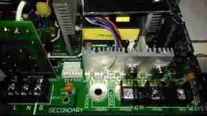
DC Outputs
DC Outputs

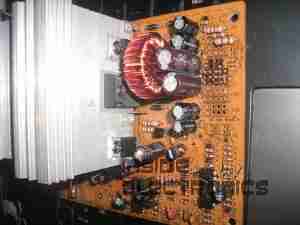
Right on the output end are a pair of large Ixys DSSK38 TO220 Dual 20A dual Schottky diodes, isolating the two outputs from each other, a nice margin on these for a 10A charger, since the diodes are paralleled each channel is capable of 40A. This prevents one bank discharging into another & allows the charger logic to monitor the voltages individually. The only issue here is the 400mV drop of these diodes introduce a little bit of inefficiency. To increase current capacity of the PCB, the aluminium heatsink is being used as the main positive busbar. From the sizing of the power components here, I would think that the same PCB & component load is used for all the chargers up to 40A, since both the PFC inductor & main power transformer are massive for a 10A output. There are unpopulated output components on this low-end model, to reduce the cost since they aren’t needed.
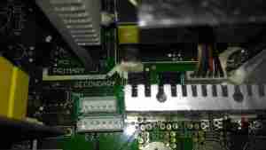
Front Panel Control Connections

A trio of headers connect all the control & sense signals to the front panel PCB, which contains all the control logic. This unit is sensing all output voltages, output current & PSU rail voltages.
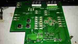
Front Panel LEDs
Front Panel LEDs

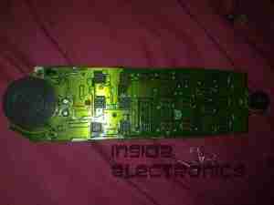
The front panel is stuffed with LEDs & 7-segment displays to show the current mode, charging voltage & current. There’s 2 tactile switches for adjustments.
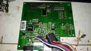
Front Panel Reverse
Front Panel Reverse

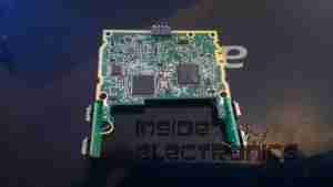
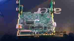
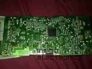
The reverse of the board has the main microcontroller – again identifying this is impossible due to the heavy conformal coat. The LEDs are being driven through a 74HC245D CMOS Octal Bus Transceiver.


Now on to the repair! I’m not particularly impressed with only getting 4 years from this unit, they are very expensive as already mentioned, so I would expect a longer lifespan. The input fuse had blown in this case, leaving me with a totally dead charger. A quick multimeter test on the input stage of the unit showed a dead short – the main AC input bridge rectifier has gone short circuit.
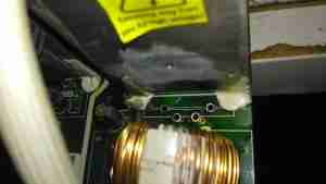
Bridge Rectifier Removed

Here the defective bridge has been desoldered from the board. It’s a KBU1008 10A 800v part. Once this was removed I confirmed there was no longer an input short, on either the AC side or the DC output side to the PFC circuit.
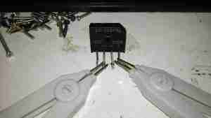
Testing The Rectifier

Time to stick the desoldered bridge on the milliohm meter & see how badly it has failed.
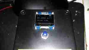
Yep, Definitely Shorted

I’d say 31mΩ would qualify as a short. It’s no wonder the 4A input fuse blew instantly. There is no sign of excessive heat around the rectifier, so I’m not sure why this would have failed, it’s certainly over-rated for the 10A charger.
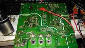
Testing Without Rectifier

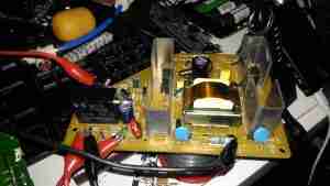
Now the defective diode bridge has been removed from the circuit, it’s time to apply some controlled power to see if anything else has failed. For this I used a module from one of my previous teardowns – the inverter from a portable TV.
Test Inverter
Test Inverter

This neat little unit outputs 330v DC at a few dozen watts, plenty enough to power up the charger with a small load for testing purposes. The charger does pull the voltage of this converter down significantly, to about 100v, but it still provides just enough to get things going.
It's Alive!
It’s Alive!

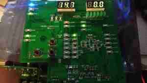
After applying some direct DC power to the input, it’s ALIVE! Certainly makes a change from the usual SMPS failures I come across, where a single component causes a chain reaction that writes off everything.
Replacement Rectifier

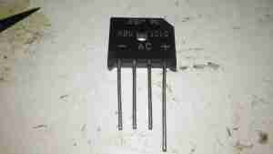
Unfortunately I couldn’t find the exact same rectifier to replace the shorted one, so I had to go for the KBU1010, which is rated for 1000v instead of 800v, but the Vf rating (Forward Voltage), is the same, so it won’t dissipate any more power.
Soldered In
Soldered In

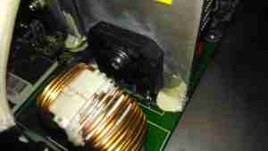
Here’s the new rectifier soldered into place on the PCB & bolted to it’s heatsink, with some decent thermal compound in between.
Input Board
Input Board

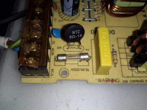
Here is the factory fuse, a soldered in device. I’ll be replacing this with standard clips for 20x5mm fuses to make replacement in the future easier, the required hole pattern in the PCB is already present. Most of the mains input filtering is also on this little daughterboard.
Fuse Replaced
Fuse Replaced

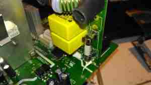
Now the fuse has been replaced with a standard one, which is much more easily replaceable. This fuse shouldn’t blow however, unless another fault develops.
Full Load Test
Full Load Test

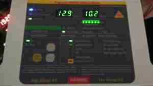
Now everything is back together, a full load test charging a 200Ah 12v battery for a few hours will tell me if the fix is good. This charger won’t be going back into service onboard the boat, it’s being replaced anyway with a new 50A charger, to better suit the larger loads we have now. It won’t be a Sterling though, as they are far too expensive. I’ll report back if anything fails!
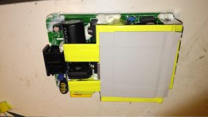
Posted on Leave a comment

Anker PowerPort Speed 5 12v DC Conversion

A few months ago I did a teardown on this Anker PowerPort Speed 5 USB charger, but I didn’t get round to detailing the conversion to 12v I had to do, so I’ll get to that now I’ve got a couple more to convert over.

Power Module
Power Module

Here’s the internals of the Anker charger once I’ve removed the casing – which like many things these days, is glued together. (Joints can be cracked with a screwdriver handle without damaging the case). There’s lots of heatsinking in here to cool the primary side switching devices & the pot core transformers, so this is the first thing to get removed.

Heatsink Removed
Heatsink Removed

Once the heatsink has been removed, the pot core transformers are visible, wrapped in yellow tape. There’s some more heatsink pads & thermal grease here, to conduct heat better. The transformers, primary side switching components & input filter capacitor have to go.

Primary Side Components Removed

Here’s the PCB once all the now redundant mains conversion components have been deleted. I’ve left the input filtering & bridge rectifier in place, as this solves the issue of the figure-8 cable on the input being reversible, polarity of the input doesn’t matter with the bridge. I’ve removed the main filter capacitor to make enough room for the DC-DC converters to be fitted.

Tails Installed
Tails Installed

Installing the tails to connect everything together is the next step, this charger requires two power supplies – the QC3 circuits need 14.4v to supply the multi-voltage modules, the remaining 3 standard ports require 5v. The DC input tails are soldered into place where the main filter capacitor was, while the outputs are fitted to the spot the transformer secondary windings ended up. I’ve left the factory Schottky rectifiers in place on the secondary side to make things a little more simple, the output voltages of both the DC-DC converters does need to be increased slightly to compensate for the diode drops though. I’ve also bypassed the mains input fuse, as at 12v the input current is going to be substantially higher than when used on mains voltage.

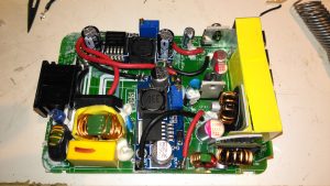
DC-DC Converters Installed

With a squeeze both the boost converter & the buck converter fit into place on the PCB.

Posted on Leave a comment

eBay Chinese Chassis Power Supply S-400-12 400W 12v 33A

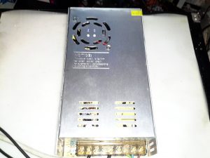
S-400-12 PSU
S-400-12 PSU

Here’s a cheap PSU from the treasure trove of junk that is eBay, rated at a rather beefy 400W of output at 12v – 33A! These industrial-type PSUs from name brands like TDK-Lambda or Puls are usually rather expensive, so I was interested to find out how much of a punishment these cheap Chinese versions will take before grenading. In my case this PSU is to be pushed into float charging a large lead acid battery bank, which when in a discharged state will try to pull as many amps from the charger as can be provided.
Rating Label
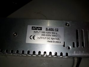
Rating Label

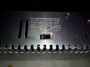
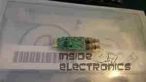
These PSUs are universal input, voltage adjustable by a switch on the other side of the PSU, below. The output voltage is also trimmable from the factory, an important thing for battery charging, as the output voltage needs to be sustained at 13.8v rather than the flat 12v from the factory.

Input Voltage Selector
Main Terminal Block
Main Terminal Block

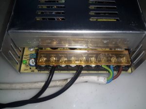
Mains connections & the low voltage outputs are on beefy screw terminals. The output voltage adjustment potentiometer & output indicator LED are on the left side.

Cooling Fan
Cooling Fan

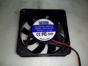
The cooling fan for the unit, which pulls air through the casing instead of blowing into the casing is a cheap sleeve bearing 60mm fan. No surprises here. I’ll probably replace this with a high-quality ball-bearing fan, to save the PSU from inevitable fan failure & overheating.

PCB Bottom
PCB Bottom

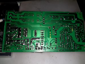
The PCB tracks are generously laid out on the high current output side, but there are some primary/secondary clearance issues in a couple of places. Lindsay Wilson over at Imajeenyus.com did a pretty thorough work-up on the fineries of these PSUs, so I’ll leave most of the in-depth stuff via a linky. There’s also a modification of this PSU for a wider voltage range, which I haven’t done in this case as the existing adjustment is plenty wide enough for battery charging duty.

Bare PCB
Bare PCB

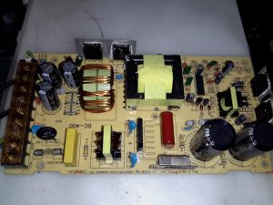
The PCB is laid out in the usual fashion for these PSUs, with the power path taking a U-route across the board. Mains input is lower left, with some filtering. Main diode bridge in the centre, with the voltage selection switch & then the main filter caps. Power is then switched into the transformer by the pair of large transistors on the right before being rectified & smoothed on the top left.

Main Switching Transistors

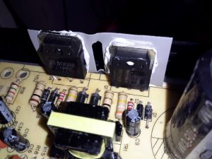
The pair of main switching devices are mounted to the casing with thermal compound & an insulating pad. To bridge the gap there’s a chunk of aluminium which also provides some extra heatsinking.

SMPS Drive IC & Base Drive Transformer

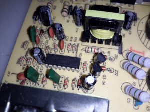
The PSU is controlled by a jelly-bean TL494 PWM controller IC. No active PFC in this cheap supply so the power factor is going to be very poor indeed.

Input Protection
Input Protection

Input protection & filtering is rather simple with the usual fuse, MOV filter capacitor & common mode choke.

Main Output Rectifiers

Beefy 30A dual diodes on the DC output side, mounted in the same fashion as the main switching transistors.

Output Current Shunt

Current measurement is done by these large wire links in the current path, selectable for different models with different output ratings.

Hot Glue Support
Hot Glue Support

The output capacitors were just floating around in the breeze, with one of them already having broken the solder joints in shipping! After reflowing the pads on all the capacitors some hot glue as flowed around them to stop any further movement.

This supply has now been in service for a couple of weeks at a constant 50% load, with the occasional hammering to recharge the battery bank after a power failure. at 13A the supply barely even gets warm, while at a load high enough to make 40A rated cable get uncomfortably warm (I didn’t manage to get a current reading, as my instruments don’t currently go high enough), the PSU was hot in the power semiconductor areas, but seemed to cope at full load perfectly well.

Laser Safety Classifications

A Smorgasbord of Acronyms

There are ANSI, OSHA, FDA (CDRH), NRPB, and military standards. The CDRH (Center for Devices and Radiological Health is part of the Food and Drug Administration and is the most relevant regulatory organization in the USA for commercial and scientific lasers. The complete CDRH document may be found at: Performance Standard for Light Emitting Products.

As of Summer 2007, there is an updated “ANSI Z136.1 (2007) Safe Use of Lasers” which among other things substitutes Class 3R for Class 3A, add Classes 1M and 2M, changes some of the control measures and terminology, and more. Nothing earth shattering though. I have not yet seen a full copy. However, there is a summary article in the June 2007 Photonics Spectra magazine. And a narrated slide show of the changes can be found in the Laser Institute of America ANSI Z.136.1 Presentation. However, without details or access to the full document, it’s an excellent cure for insomnia at best. 🙂 Also see: Wikipedia: Laser Safety, which includes many references and some links.

The best discussion of the various classifications, plus general treatment of the topic, is a book by Sliney and Wolbarsht, “Safety with Lasers and Other Optical Sources”, Plenum Press, New York. While they will agree with each other in most respects, some differences will result in a particular laser changing classes depending on which standard is used. The major criteria are summarized below.

Note: I may use Class 1 and Class I, Class 2 and Class II, Class 3 and Class III, and Class 4 and Class IV interchangeably. They are equivalent.

The following is based on material from the University of Waterloo – Laser Safety Manual.

All lasers are classified by the manufacturer and labelled with the appropriate warning labels. Any modification of an existing laser or an unclassified laser must be classified by the Laser Safety Officer prior to use. The following criteria are used to classify lasers:

  1. Wavelength. If the laser is designed to emit multiple wavelengths the classification is based on the most hazardous wavelength.
  2. For continuous wave (CW) or repetitively pulsed lasers the average power output (Watts) and limiting exposure time inherent in the design are considered.
  3. For pulsed lasers the total energy per pulse (joule), pulse duration, pulse repetition frequency and emergent beam radiant exposure are considered.

Lasers are generally classified and controlled according to the following criteria:

  • Class I lasers – Lasers that are not hazardous for continuous viewing or are designed in such a way that prevent human access to laser radiation. These consist of low power lasers or higher power embedded lasers (e.g., laser printer or DVD burner).
  • Class II visible lasers (400 to 700 nm) – Lasers emitting visible light which because of normal human aversion responses, do not normally present a hazard, but would if viewed directly for extended periods of time. This is like many conventional high intensity light sources.
  • Class IIa visible lasers (400 to 700 nm) – Lasers emitting visible light not intended for viewing, and under normal operating conditions would not produce a injury to the eye if viewed directly for less than 1,000 seconds (e.g., bar code scanners).
  • Class IIIa lasers – Lasers that normally would not cause injury to the eye if viewed momentarily but would present a hazard if viewed using collecting optics such as a magnifier or telescope).
  • Class IIIb lasers – Lasers that present an eye and skin hazard if viewed directly. This includes both intrabeam viewing and specular reflections. Class IIIb lasers do not produce a hazardous diffuse reflection except when viewed at close proximity.
  • Class IV lasers – Lasers that present an eye hazard from direct, specular and diffuse reflections. In addition such lasers may be fire hazards and produce skin burns.

Here is another description, paraphrased from the CORD course: “Intro to Lasers”. (Cord Communications. Lasers.) It relates the laser classifications to common laser types and power levels:

  • Class I – EXEMPT LASERS, considered ‘safe’ for intrabeam viewing. Visible beam.Maximum power less than 0.4 uW for long term exposure (greater than 10,000 seconds). Looking at a Class I laser will not cause eye damage even where the entire beam enters the eye and it is being stared at continuously.A laser may also be labeled as Class I if it is entirely enclosed and not accessible without disassembly using tools. Thus, a DVD burner with a 150 mW laser diode (normally a Class IIIB laser) would still be considered Class I.
  • Class II – LOW-POWERED VISIBLE (CW) OR HIGH PRF LASERS, won’t damage your eye if viewed momentarily. Visible beam.Maximum power less than 1 mW for HeNe laser.
  • Class IIIa – MEDIUM POWER LASERS, focused beam can injure the eye.HeNe laser power 1.0 to 5.0 mW.
  • Class IIIb – MEDIUM POWER LASERS, diffuse reflection is not hazardous, doesn’t present a fire hazard.Visible Argon laser power 5.0 mW to 500 mW.
  • Class IV – HIGH POWER LASERS, diffuse reflection is hazardous and/or a fire hazard.

The classifications depend on the wavelength of the light as well and as noted, there may be additional considerations for each class depending on which agency is making the rules. For example, the NRPB (British) adds a requirement for Class IIIa that the power density for a visible laser not exceed 25 W/m2 which would thus bump some laser pointers with tightly focused beams from Class IIIa to Class IIIb. For more information on laser pointer safety and the NRPB classifications, see the NRPB Laser Pointer Article.

In the US, start with the Center for Devices and Radiological Health (CDRH), part of the Food and Drug Administration (FDA). See the section: Regulations for Manufacturers of Lasers and Laser Based Equipment for more info on how to find the relevant guidance documents.

For additional information on laser safety and laser safety classifications, see the section: Laser Safety Sites (May Also Include Other Laser Information).

Here is a table of the CDRH classification and labeling requirements for commercial laser products:

Here are some excerpts from the Center for Devices and Radiological Health (CDRH) regulation 21 CFR 1040.10 and 21 CFR 1040.11, the standard classification for lasers are as follows with some additional comments by Wes Ellison (erl@sunflower.com):

  • Class I laser productsNo known biological hazard. The light is shielded from any possible viewing by a person and the laser system is interlocked to prevent the laser from being on when exposed. (large laser printers such as the DEC LPS-40 had a 10 mW HeNe laser driving it which is a Class IIIb laser, but the printer is interlocked so as to prevent any contact with the exposed laser beam, hence the device produces no known biological hazard, even though the actual laser is Class IIIb. This would also apply to CD/DVD/Blu-ray players and recorders (which might have Class IIIb laser diodes of 100 mW or more) and small laser, as they are Class I devices).
  • Class II laser productsPower up to 1 milliwatt. These lasers are not considered an optically dangerous device as the eye reflex will prevent any occular damage. (I.e., when the eye is hit with a bright light, the eye lid will automatically blink or the person will turn their head so as to remove the bright light. This is called the reflex action or time. Class II lasers won’t cause eye damage in this time period. Still, one wouldn’t want to look at it for an extended period of time.) Caution labels (yellow) should be placed on the laser equipment. No known skin exposure hazard exist and no fire hazard exist.
  • Class IIIa laser productsPower output between 1 milliwatt and 5 milliwatt. These lasers can produce spot blindness under the right conditions and other possible eye injuries. Products that have a Class IIIa laser should have a laser emission indicator to tell when the laser is in operation. They should also have a Danger label and output aperture label attached to the laser and/or equipment. A key operated power switch SHOULD be used to prevent unauthorized use. No known skin hazard of fire hazard exist.
  • Class IIIb laser productsPower output from 5 milliwatts to 500 milliwatts. These lasers are considered a definite eye hazard, particularly at the higher power levels, which WILL cause eye damage. These lasers MUST have a key switch to prevent unauthorized use, a laser emission indicator, a 3 to 5 second time delay after power is applied to allow the operator to move away from the beam path, and a mechanical shutter to turn the beam off during use. Skin may be burned at the higher levels of power output as well as the flash point of some materials which could catch fire. (I have seen 250 mW argons set a piece of red paper on fire in less than 2 seconds exposure time!) A red DANGER label and aperture label MUST be affixed to the laser.
  • Class IV laser productsPower output >500 milliwatts. These CAN and WILL cause eye damage. The Class IV range CAN and WILL cause materials to burn on contact as well as skin and clothing to burn. These laser systems MUST have:A key lockout switch to prevent unauthorized use Inter-locks to prevent the system from being used with the protective covers off, emission indicators to show that the laser is in use, mechanical shutters to block the beam, and red DANGER labels and aperture labels affixed to the laser.

    The reflected beam should be considered as dangerous as the primary beam. (Again, I have seen a 1,000 watt CO2 laser blast a hole through a piece of steel, so imagine what it would do to your eye !)

  • Registration of laser systemsAny laser system that has a power output of greater than 5 milliwatts MUST be registered with the FDA and Center for Devices and Radiological Health if it has an exposed beam, such as for entertainment (I.E. Laser light shows) or for medical use (such as surgery) where someone other than the operator may come in contact with it. (This is called a ‘variance’ and I have filled them out and submitted them and they ARE a royal pain in the backside!)

Sometimes, you will come across a laser subassembly that has a sticker reading something like: “Does not Comply with 21 CFR”. All this means is that since the laser was mounted inside another piece of equipment and would not normally be exposed except during servicing, it does not meet all the safety requirements for a laser of its CDRH classification such as electrical interlocks, turn-on delay, or beam shutter. This label doesn’t mean it is any more dangerous than another laser with similar specifications as long as proper precautions are taken – such as adding the missing features if using the laser for some other purpose!

(From: Johannes Swartling (Johannes.Swartling@fysik.lth.se).)

It is not the laser in itself that is given a class number, but the whole system. A system which is built around a very powerful laser can still be specified as Class I, if there is no risk of injury when operating the system under normal conditions. For example, CD players are of class I, but the (IR) laser diode may in itself be powerful enough to harm the eye. CD players are designed so that the laser light won’t escape the casing.

When it comes to laser safety and exposure levels the regulations are fairly complicated and I will not go into details. Basically, there are tables with ‘safe’ levels of exposures. The exposure has to be calculated in a certain way which is unique to each case, depending on among other things: laser power, divergence, distance, wavelength, pulse duration, peak power, and exposure time.. Although it is true that near infrared lasers are potentially more dangerous than visible because you can’t see the radiation, it is incorrect to say that it must be, say, Class III. The level of exposure may be so low that it can be a Class I (note that Class II lasers are always visible though, so infrared lasers are either of Class I or Class III or higher).

(From: John Hansknecht (vplss@lasersafetysystems.com).)

OSHA STD-01-05-001 – PUB 8-1.7 – Guidelines for Laser Safety and Hazard Assessment is an “open source” release of the ANSI Z136.1-1986 standard. It is not as up to date as the present ANSI standard (ANSI Z136.1-2015), but it’s close. The ANSI standard is considered to be the authoritative guide for safe work practices and would be a better source than a University safety manual. The key point to understand is if a laser accident ever occurs and a lawsuit ensues, the lawyers will be checking to see if the facility was following the “recognized best work practices”.

Laser Safety Systems LLC, a supplier of laser safety products, has a good intro page for anyone serious about becoming ANSI compliant at A Practical Guide to Laser Class 4 Entryway Control Requirements.

Hobbyist Projects and Laser Safety Classifications

While many of the partial circuits and complete schematics in this document can and have been used in commercial laser products, important safety equipment has generally been omitted to simplify their presentation. These range from simple warning labels for low power lasers (Class I, II, IIIa) to keyswitch and case interlocks, beam-on indicators, and other electrical and mechanical safety devices for higher power lasers. Laser safety is taken very seriously by the regulatory agencies. Each classification has its own set of requirements.

The following brief summary is just meant to be a guide for personal projects and experimentation (non-commercial use) – the specifics for each laser class may be even more stringent:

  • For diode lasers and HeNe lasers outputting 5 mW or less (Classes 1, II, IIIa), packaging to minimize the chances of accidental exposure to the beam and standard laser warning labels should be provided.
  • Where the case can be opened without the use of tools, interlocks which disable the beam are essential to prevent accidental exposure to laser radiation (Class IIIa and above). Their activation should also remove power and bleed off any dangerous voltages (ALL HeNe and argon/krypton lasers).
  • A beam-on indication is highly desirable especially for lasers emitting invisible IR (or UV).

Aside from their essential safety function, laser warning or danger stickers DO add something in the professional and high-tech appearance department. Companies selling laser accessories will likely offer genuine CDRH approved stickers. If you are selling any laser based equipment, you’ll need them (and a lot more). For hobbyist, some semi-standard unofficial samples can be found in the next section.

Applications of a 1mW Helium-Neon Laser

There are many uses for even a 1 mW helium-neon laser. Most of these same sorts of things can also be done with a collimated diode laser (though some laser diodes may not have the needed coherence properties for applications like interferometry and hologram generation).

Below are just a few possibilities.

(Portions from: Chris Chagaris (pyro@grolen.com).)

  • Basic optical experimentation such demonstrating the principals of refraction, reflection, diffraction and polarization.
  • Interferometer construction: With a small laser and a few simple optics, this device will allow you to perform many interesting experiments.
  • Free-space optical communications: using some basic electronics for modulation.
  • Fiber Optic Experimentation.
  • Viewing of holograms.
  • Hologram generation: However, I’d suggest a slightly higher powered laser for this.
  • Construction of a basic laser light show. A higher power laser could be substituted when budget constraints allow. 🙂
  • Laser surveillance.
  • Laser tachometer.
  • Laser burglar alarm.
  • Laser gyroscope.
  • Studying fluid dynamics.
  • Applications in construction for calculating distance, leveling, aid in pipe laying, etc.

He-Ne Lasers – Introduction

A helium-neon (henceforth abbreviated HeNe) laser is basically a fancy neon sign with mirrors at both ends. Well, not quite, but really not much more than this at first glance (though the design and manufacturing issues which must be dealt with to achieve the desired beam characteristics, power output, stability, and life span, are non-trivial). The gas fill is a mixture of helium and neon gas at low pressure. A pair of mirrors – one totally reflective (called the High Reflector or HR), the other partially reflective (called the Output Coupler or OC) at the wavelength of the laser’s output – complete the resonator assembly. This is called a Fabry-Perot cavity (if you want to impress your friends). The mirrors may be internal (common on small and inexpensive tubes) or external (on precision high priced lab quality lasers). Electrodes sealed into the tube allow for the passage of high voltage DC current to excite the discharge.

Note that a true laser jock will further abbreviate “HeNe laser” to simply “HeNe”, pronounced: Hee-nee. Their laser jock colleagues and friends then know this really refers to a laser! 🙂 While other types of lasers are sometimes abbreviated in an analogous manner, it is never to the same extent as the HeNe.

I still consider the HeNe laser to be the quintessential laser: An electrically excited gas between a pair of mirrors. It is also the ideal first laser for the experimenter and hobbyist. OK, well, maybe after you get over the excitement of your first laser pointer! 🙂 HeNe’s are simple in principle though complex to manufacture, the beam quality is excellent – better than anything else available at a similar price. When properly powered and reasonable precautions are taken, they are relatively safe if the power output is under 5 mW. And such a laser can be easily used for many applications. With a bare HeNe laser tube, you can even look inside while it is in operation and see what is going on. Well, OK, with just a wee bit of imagination! 🙂 This really isn’t possible with diode or solid state lasers.

I remember doing the glasswork for a 3 foot long HeNe laser (probably based on the design from: “The Amateur Scientist – Helium-Neon Laser”, Scientific American, September 1964, and reprinted in the collection: “Light and Its Uses” [5]). This included joining side tubes for the electrodes and exhaust port, fusing the electrodes themselves to the glass, preparing the main bore (capillary), and cutting the angled Brewster windows (so that external mirrors could be used) on a diamond saw. I do not know if the person building the laser ever got it to work but suspect that he gave up or went on to other projects (which probably were also never finished). And, HeNe lasers are one of the simplest type of lasers to fabricate which produce a visible continuous beam.

Some die-hards still construct their own HeNe lasers from scratch. Once all the glasswork is complete, the tube must be evacuated, baked to drive off surface impurities, backfilled with a specific mixture of helium to neon (typically around 7:1 to 10:1) at a pressure of between 2 and 5 Torr (normal atmospheric pressure is about 760 Torr – 760 mm of mercury), and sealed. The mirrors must then be painstakingly positioned and aligned. Finally, the great moment arrives and the power is applied. You also constructed your high voltage power supply from scratch, correct? With luck, the laser produces a beam and only final adjustments to the mirrors are then required to optimize beam power and stability. Or, more, likely, you are doing all of this while your vacuum pumps are chugging along and you can still play with the gas fill pressure and composition. What can go wrong? All sorts of things can go wrong! With external mirrors, the losses may be too great resulting in insufficient optical gain in the resonant cavity. The gas mixture may be incorrect or become contaminated. Seals might leak. Your power supply may not start the tube, or it may catch fire or blow up. It just may not be your day! And, the lifetime of the laser is likely to end up being only a few hours in any case unless you have access to an ultra-high vacuum pumping and bakeout facility. While getting such a contraption to work would be an extremely rewarding experience, its utility for any sort of real applications would likely be quite limited and require constant fiddling with the adjustments. Nonetheless, if you really want to be able to say you built a laser from the ground up, this is one approach to take! (However, the CO2 and N2 lasers are likely to be much easier for the first-time laser builder.)

However, for most of us, ‘building’ a HeNe laser is like ‘building’ a PC: An inexpensive HeNe tube and power supply are obtained, mounted, and wired together. Optics are added as needed. Power supplies may be home-built as an interesting project but few have the desire, facilities, patience, and determination to construct the actual HeNe tube itself.

The most common internal mirror HeNe laser tubes are between 4.5″ and 14″ (125 mm to 350 mm) in overall length and 3/4″ to 1-1/2″ (19 mm to 37.5 mm) in diameter generating optical power from 0.5 mW to 5 mW. They require no maintenance and no adjustments of any kind during their long lifetime (20,000 hours typical). Both new and surplus tubes of this type – either bare or as part of complete laser heads – are readily available. Slightly smaller tubes (less than 0.5 mW) and much larger tubes (up to approximately 35 mW) are structurally similar (except for size) to these but are not as common.

Much larger HeNe tubes with internal or external mirrors or one of each (more than a *meter* in length!) and capable of generating up to 250 mW of optical power have been available and may turn up on the surplus market as well (but most of these are quite dead by now). The most famous of these (as lasers go) is probably the Spectra-Physics model 125A whose laser head is over 6 feet in length. It was only rated 50 mW (633 nm), but new samples under optimal conditions may have produced more than 200 mW. Even more powerful ones have been built as research projects. I’ve seen photos of a Hughes HeNe laser with a head around 8 feet in length that required a 6 foot rack-mount enclosure for the exciter.

Monster Vintage Hughes HeNe Laser System

Its output power is unknown, but probably less than that of the SP-125A. The largest single transverse mode (SM, with a TEM00 beam profile) HeNe lasers in current production by a well known manufacturer like Melles Griot are rated at about 35 mW minimum over an expected lifetime of 20,000 hours or more, though new samples may exceed 50 mW. However, HeNe lasers rated up to at least 70 mW SM and 100 mW MM are available. Manufacturers include: CDHC-Optics (China), Spectral Laser (Italy), and PLASMA, JSC (Russia). However, the lifetime over which these specifications apply is not known and may be much shorter.

Highly specialized configurations, such as a triple XYZ axis triangular cavity HeNe laser in a solid glass block for an optical ring laser gyro, also exist but are much much less common. Most HeNe lasers operate CW (Continuous Wave) producing a steady beam at a fixed output power unless the power is switched on and off or modulated (or someone sticks their finger in the beam and blocks it!). (At least they are supposed to when in good operating condition!) However, there are some mode-locked HeNe lasers that output a series of short pulses at a high repetition rate. And, in principle, it is possible to force a HeNe laser with at least one external mirror to “cavity dump” a high power pulse (perhaps 100 times the CW power) a couple of nanoseconds long by diverting the internal beam path with an ultra high speed acousto-optic deflector. But, for the most part, such systems aren’t generally useful for very much outside some esoteric research areas and in any case, you probably won’t find any of these at a local flea market or swap meet, though eBay can’t be ruled out! 🙂

Nearly all HeNe lasers output a single wavelength and it is most often red at 632.8 nm. (This color beam actually appears somewhat orange-red especially compared to many laser pointers using diode lasers at wavelengths between 650 and 670 nm). However, green (543.5 nm), yellow (594.1 nm), orange (604.6 and 611.9 nm), and even IR (1,152, 1.523, and 3,921 nm) HeNe lasers are available. There are a few high performance HeNe lasers that are tunable and very expensive. And, occasionally one comes across laser tubes that output two or more wavelengths simultaneously. Although some tubes are designed this way, it is more likely to be a ‘defect’ resulting from a combination of high gain and insufficiently narrow band optics. Such tubes tend to be unstable with the relative power varying among the multiple wavelengths more or less at random.

Note that the single wavelength described above usually consists of more than one longitudinal mode or lasing line (more on this later). However, some HeNe lasers are designed to produce a highly stable single optical frequency or two closely spaced optical frequencies. These are used in scientific research and metrology (measurement) applications, described in more detail below.

Current major HeNe laser manufacturers include Melles-Griot, JDS Uniphase, and LASOS. This is far fewer than there were only a few years ago. So, you may also find lasers from companies like Aerotech, Hughes, Siemens, and Spectra-Physics that have since gotten out of the HeNe laser business or have been bought out, merged, or changed names. For example, the HeNe laser divisions of Aerotech and Hughes were acquired by Melles Griot; Sieman’s HeNe laser product line is now part of LASOS; and Spectra-Physics which was probably the largest producer of HeNe lasers from the very beginning gradually eliminated all HeNe lasers from its product line over the last few years. HeNe tubes, laser heads, and complete lasers from any of these manufacturers are generally of very high quality and reliability.

HeNe lasers have been found in all kinds of equipment including:

  • Consumer: Supermarket checkout UPC and other barcode scanners. early laser printers, early LaserDisc players.
  • Advertising/entertainment: Holography, small laser shows.
  • Measurement: Optical surveying, interferometric metrology and velocimetry, other non-contact measurement and monitoring, ring laser gyro.
  • Construction: Laser level, tunnel boring, alignment of saw mill wood cutting, general surveying.
  • Industrial: Automotive and other alignment; parts detection, counting, and positioning; particle counting.
  • Biotechnology: Blood cell analysis (cytometry), laser induced fluorescence of everything from whole cells to single DNA bases, laser tweezers, confocal microscopy, Raman spectroscopy, anesthesia and other gas analysis.
  • Medical/surgical: Patient positioning systems for diagnostic and treatment machines, alignment of high power CO2 and YAG treatment lasers and pointing beams.

Nowadays, many of these applications are likely to use the much more compact lower (drive) power solid state diode laser. (You can tell if you local ACME supermarket uses a HeNe laser in its checkout scanners by the color of the light – the 632.8 nm wavelength beam from a HeNe laser is noticeably more orange than the 660 or 670 nm deep red from a typical diode laser type.)

Melles Griot (now part of IDEX Optics and Photonics Marketplace. Catalogs used to include several pages describing HeNe laser applications. I know this was present in the 1998 catalog but has since disappeared and I don’t think it is on their Web site.

Also see the section: Some Applications of a 1 mW Helium-Neon Laser for the sorts of things you can do with even a small HeNe laser.

Since a 5 mW laser pointer complete with batteries can conveniently fit on a keychain and generate the same beam power as an AC line operated HeNe laser almost half a meter long, why bother with a HeNe laser at all? There are several reasons:

  • For many applications including holography and interferometry, the high quality stable beam of a HeNe laser is unmatched (at least at reasonable cost, perhaps at all) by laser diodes (though this is apparently changing at least for some diode lasers. See the section: Holography Using Cheap Diode Lasers. In particular, the coherence length and monochromicity of even a cheap HeNe laser are excellent and the beam profile is circular and nearly ideal Gaussian TEM00 so that simple spherical optics can be used for beam manipulation. Bare edge emitting laser diodes (the only visible type currently available) on the other hand always produce a wedge shaped beam and have some amount of astigmatism. Correcting this to the equivalent quality of a HeNe laser is difficult and expensive.
  • As noted in the chapter: Diode Lasers, it is all too easy to ruin them in the blink of an eye (actually, the time it takes light to travel a few feet). It would not take very long to get frustrated burning out $50 diodes. So, the HeNe laser tube may be a better way to get started. They are harder to damage through carelessness or design errors. Just don’t get the polarity reversed or exceed the tube’s rated current for too long – or drop them on the floor! And, take care around the high voltage!
  • Laser diode modules at a wavelength of 635 nm (close to the 632.8 nm wavelength of red HeNe lasers) may still be somewhat more expensive than surplus HeNe tubes with power supplies. However, with the increasing popularity of DVD players and DVDROM drives, this situation probably won’t last long.

However, the market for new HeNe lasers is still in the 100,000 or more units per year. What can you say? If you need a stable, round, astigmatism-free, long lived, visible 1 to 10 mW beam for under $500 (new, remember!), the HeNe laser is still the only choice.

Posted on Leave a comment

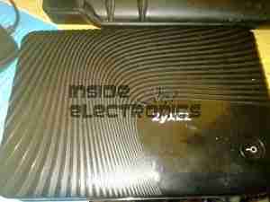
ZyXel WAP3205 Repair

Here is a ZyXel WAP3205 WiFi Access Point that has suffered a reverse polarity event, due to an incorrect power supply being used with the unit.

ZyXEL WAP3205
ZyXEL WAP3205

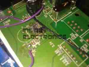
While most electronic gadgets are protected against reverse polarity with a blocking diode, this unit certainly wasn’t. Applying +12v DC the wrong way round resulted in this:

Blown Switchmode IC
Blown Switchmode IC (Fuzzy Focus)

That is the remains of the 3.3v regulator IC, blown to smithereens & it even attempted an arson attack. Luckily this was the only damaged component, & I was able to repair the unit by replacing the switching IC with a standalone regulator. (Replacing the IC would have been preferable, if there was anything left of it to obtain a part number from).

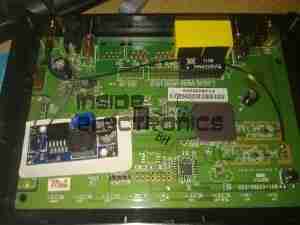
I scraped away the pins of the IC to clear the short on the input supply, removed the switching inductor, & tacked on an adjustable regulator module set to 3.3v. Luckily the voltage of the supply is handily marked on the PCB next to the circuit.

Replacement PSU
Replacement PSU

Replacement SMPS in place on top of the PCB. The output of the supply is connected to one of the pads of L4 (on my unit just an 0 ohm link), the +12v input is connected to the + rail side of C8 & C7 & the final ground connection is hooked in to the back of the barrel jack.

After this replacement, the unit booted straight up as if nothing had happened. All the logic is undamaged!

Makerplate
Makerplate
Posted on Leave a comment

Water Management System PCB Revisions

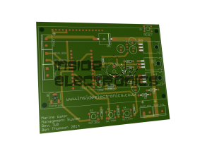
OK, a few revisions have been made to the water management PCB, mainly to reduce the possibility of the brushed DC motors in the water pumps from causing the MCU to crash, with the other changes to the I/O connector positioning & finally upgrading the reverse blocking diode to a 10A capable version rather than 5A.

Water Management PCB

Thanks to Mayhew Labs with the WebGerber image generator for the render.

Posted on Leave a comment

Ultracapacitor Charge Balancing

Balancer
Balancer

I have finally  got round to designing the balancing circuitry for my ultracapacitor banks, which have a total voltage of 15v when fully charged. The 2600F capacitors have a max working voltage of 2.5v each, so to ensure reliable operation, balancing is required to make sure that each capacitor is charged fully.

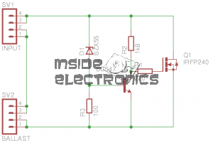
The circuit above is a simple shunt regulator, which uses a 2.2v zener diode to regulate the voltage across the capacitor.

A 10W 1Ω resistor is connected to the BALLAST header, while the capacitor is connected across the INPUT. Once the voltage on the capacitor reaches 2.6v, the MOSFET begins to conduct, the 1Ω resistor limiting current to ~2.6A.

Each capacitor in the series string requires one of these connected across it.

PCB
PCB

Below is a link to the Eagle project archive for this. Includes schematic, board & gerber files.

[download id=”5555″]

Posted on Leave a comment

Vintage Optical Block

Top
Top

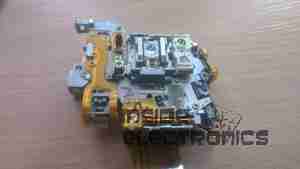
I thought this would be of interest, as it’s from a drive circa 2001, (DVD-CD-RW).

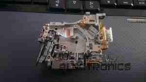
It’s the biggest & most complex optical block I’ve ever seen, with totally separate beam paths for the IR CD beam & the visible DVD beam. It also combines the use of bare laser diodes & combined diode/photodiode array modules for the pickup.


Cover Removed
Cover Removed

Here’s a look at the optics inside the sled, on the left is a bare laser diode & photodiode array, for the CD reading, and the bottom right has the DVD combined LD/PD array module. The beam from the CD diode has to pass though some very complex beam forming optics & a prism to fold it round to the final turning mirror to the objective lens at top center.
There are also two separate photodiodes which are picking up the waste beam from the prisms, most likely for power control.

Posted on 1 Comment

MicroVision ShowWX+ HDMI Laser Pico Projector

Info
Info

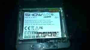
Here’s the teardown of the projector itself! On the right is the info label from the projector, which covers the flex ribbon to the VGA/composite input board below.

This unit is held together with Allen screws, but is easy to get apart.


PicoP Display Engine

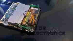
Here’s the insides of the projector, with just the top cover removed. The main board can be seen under the shielding can, the Micro HDMI connector is on the left & the MicroUSB connection is on the right. The USB connection is solely for charging the battery & provides no data interface to the unit.

On top of the main board is the shield can covering the PicoP Display Engine driver board, this shield was soldered on so no peek inside unfortunately!

Laser Module
Laser Module

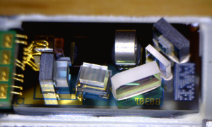
The laser module itself is in the front of the unit, the laser assemblies are closest to the camera, on the left is the Direct Doubled Green module, in the centre is the blue diode, and the red diode on the right. Inside the module itself is an arrangement of mirrors & beamsplitters, used to combine the RGB beams from the lasers into a single beam to create any colour in the spectrum.

Module Innards
Module Innards


Here is the module innards revealed, the laser mounts are at the top of the screen, the green module is still mounted on the base casting.
The three dichroic mirrors in the frame do the beam combining, which is then bounced onto the mirror on the far left of the frame, down below the MEMs. From there a final mirror directs the light onto the MEMs scanning mirror before it leaves through the output window.

A trio of photodiodes caters for beam brightness control & colour control, these are located behind the last dichroic turning mirror in the centre of the picture.

Green Module Cavity
Green Module Cavity

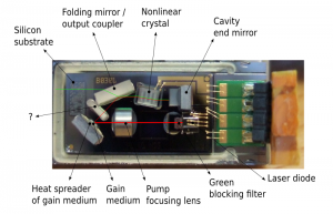
This is inside the green laser module, showing the complexity of the device. This laser module is about the size of a UK 5p coin!

Green Module Labeled


And here on the left is the module components labelled.


Main PCB Top
Main PCB Top

Here is the main PCB, with the unit’s main ARM CPU on the right, manufactured by ST.

User buttons are along the sides.


Main PCB Bottom
Main PCB Bottom

Other side of the main board, with ICs that handle video input from the HDMI connector, battery charging via the USB port & various other management.


Posted on Leave a comment

Cisco 2G Fibre Channel SFP Module

2G Fibre Tranciever
2G Fibre Transceiver

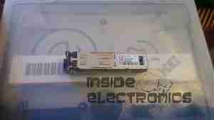
Here is a 2Gbit Fibre Channel transceiver from Cisco Systems in SFP module format.

Shield Removed
Shield Removed


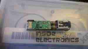
Here the shield has been removed from the bottom of the module (it just clips off). The bottom of the PCB can be seen, with the copper interface on the left & the rubber boots over the photodiode & 850 nm laser on the right.

PCB Bottom
PCB Bottom

Here the PCB has been completely removed from the frame, the fibre ends slide into the rubber tubes on the right.

PCB Top
PCB Top


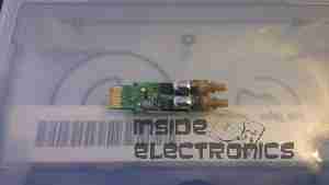
Top of the PCB, showing the chipset. There are a pair of adjustment pots under some glue, next to the chipset, presumably for adjusting laser power & receive sensitivity. The laser diode & photodiode are inside the soldered cans on the right hand side of the board, with the optics required to couple the 850nm near-IR light into the fibre.

Posted on 1 Comment

Combo Microwave

Electronics Bay
Electronics Bay

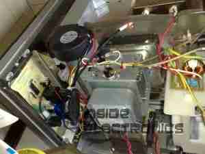
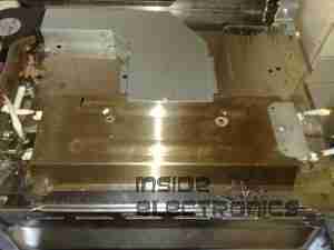
Here are the internals of a cheap Microwave/Convection Oven combo. Electronics bay is pretty much the same as a standard microwave, with the magnetron, transformer & diode/capacitor voltage doubler, with the addition of an extra fan & a pair of nichrome elements to provide the convection oven function.

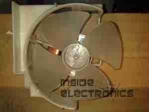
Convection Fan
Convection Fan

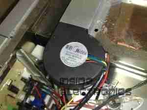
Convection blower which keeps the cooking vapours & smoke away from the elements, & circulates the hot air around the cooking chamber. This is a 12v DC centrifugal type blower.

Convection Element
Convection Element

The elements are inside this steel shield, air duct extends from the centre.

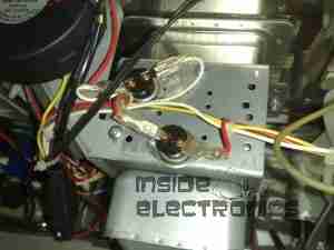
Thermal Cutouts
Thermal Cutouts

This oven has a pair of thermal switches on the magnetron.

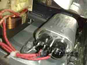
Capacitor & Diode
Capacitor & Diode

The usual capacitor/diode voltage doubler in the magnetron power supply. The transformer is visible to the left.

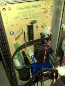
Controller
Controller

Electronic controller PCB. This has a pair of relays that switch the elements & the magnetron transformer.

Posted on Leave a comment

Belling Microwave


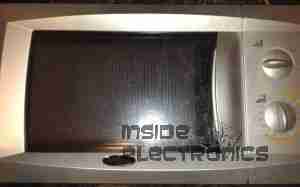
Front
Front

Here is a cheap no frills microwave oven, which died after a few weeks of normal use.

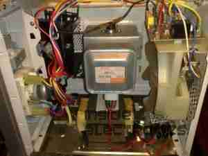
Electronics Bay
Electronics Bay

Cover removed, showing the internals. Front of the microwave is on the left.

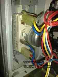
Timer
Timer

Closeup of the timer unit. Cheap & nasty.

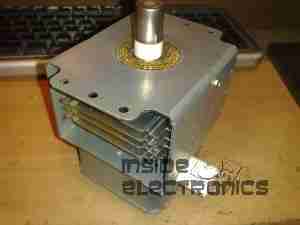
Magnetron
Magnetron

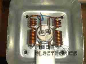
Magnetron removed from the oven. Antenna is on the top,  cooling fins visible in the center. White conector at the bottom is the filament terminals.

Magnetron Chokes
Magnetron Chokes

Chokes on the magnetron’s filament connections. These prevent microwave energy from feeding back into the electronics bay through the connections.

Magnetron Assembly
Magnetron Assembly

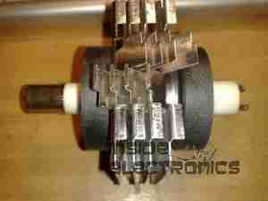
Magnetron cooling fins, tube & magnets removed from the frame.

Magnetron Tube
Magnetron Tube

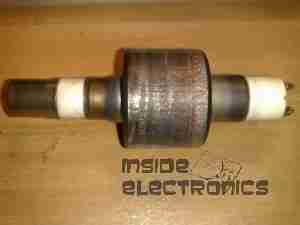
Bare magnetron tube.

Power Input Board
Power Input Board

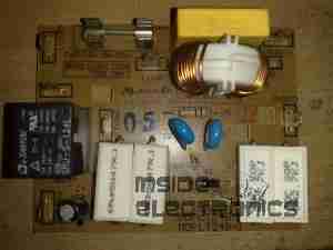
This PCB does some rudimentary power conditioning, power resistors are in series with the live feed to the power trasformer, to prevent huge power up surge. When the transformer energizes the relay, which is in parallel with the resistors, switches them out a fraction of a second after, providing full power to the transformer.
Standard RFI choke & capacitor at the top of the board, with the input resistor.

Transformer
Transformer

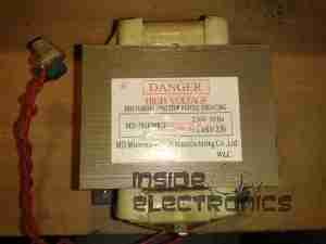
Power transformer to supply the magnetron with high voltage.
Power output is ~2kV at ~0.5A. Pair of spade terminals are the low voltage filament winding.

Capacitor
Capacitor

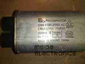
HV Capacitor. This along with the diode form a voltage doubler, to provide the magnetron with ~4kV DC.

Diode
Diode

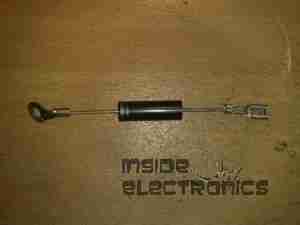
HV diode stack.

Fuse Element
Fuse Element

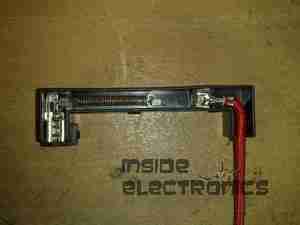
Internals of the HV fuse. Rated for ~0.75A at 5kV. The fuse element is barely visible attached to the end of the spring. Connects between the transformer & the capacitor.

Cooling Fan
Cooling Fan

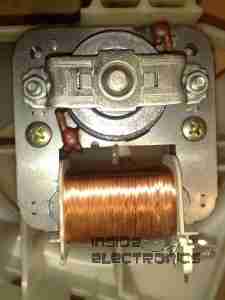
Cooling fan for the magnetron. Drive is cheap shaded pole motor.

Fan Motor
Fan Motor

Fan motor. Basic 240v shaded pole induction type.

Posted on Leave a comment

532nm DPSS Module

DPSS Module
DPSS Module

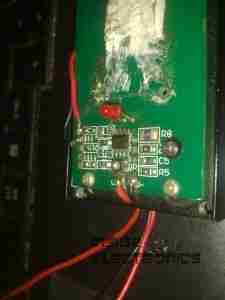
A quick post documenting a DPSS laser module i salvaged from a disco scanner. Estimated output ~80mW

Diode Connection
Diode Connection

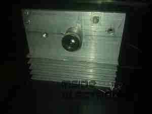
Connection to the 808nm pump diode on the back of the module. There is a protection diode soldered across the diode pins. (Not visible). Note heatsinking of the module.

Driver PCB
Driver PCB

Driver PCB. This module was originally 240v AC powered, with a transformer mounted on the PCB with a built in rectifier & filter capacitor. I converted it to 5v operation. Emission LED on PCB.

Output
Output

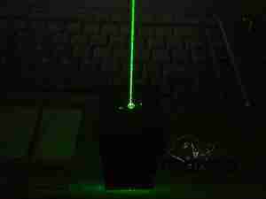
Output beam from the module.

Posted on Leave a comment

455nm Laser Head

Aixiz Module
Aixiz Module

Here’s my prototype 455nm laser head, constructed from the front section of an Aixiz module threaded into a heatsink from an old ATX power supply. This sink has enough thermal mass for short 1W testing.

Connection
Connection

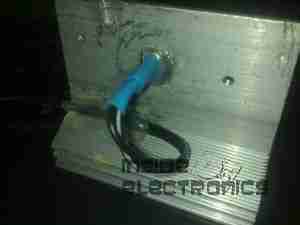
Connection to the laser diode at the back of the heatsink. Cable is heat shrink covered for strain relief, & hot glued to the sink for extra strain relief.

Beamshot 1
Beamshot 1

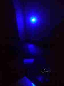
Looking down the beam, laser is under the camera. Operating around 1.2W here

Beamshot 2
Beamshot 2

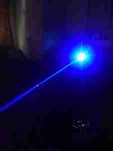
Camera looking towards the laser. Again operating at ~1.2W output power.

Posted on Leave a comment

Power Pack Regulator Update

7.5v Regulator
7.5v Regulator

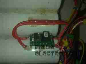
To help make my system more efficient, a pair of switching regulators has been fitted, the one shown above is a Texas Instruments PTN78060 switchmode regulator module, which provides a 7.5v rail from the main 12v battery pack.

A Lot like the LM317 & similar linear regulators, these modules require a single program resistor to set the output voltage, but are much more efficient, around the 94% mark at the settings used here.

The 7.5v rail supplies the LM317 constant current circuit in the laser diode driver subsection. This increases efficiency by taking some voltage drop away from the LM317.

5v Regulator
5v Regulator

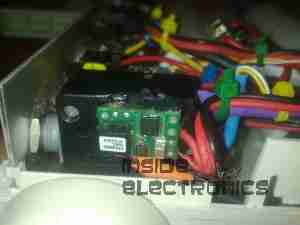
The 7.5v rail also provides power to this Texas Instruments  PTH08000 switchmode regulator module, providing the 5v rail for the USB port power.

Posted on Leave a comment

Portable Power Pack Charger

A quick update to my portable power pack, a mains charging port. Uses a universal DC barrel jack.

Connection to the battery. 1N4001 reverse protection diode under the blue heatshrink tubing. I used a surplus PC CD-ROM audio cable (grey lead). Seen here snaking behind the battery to the DC In Jack.

Posted on Leave a comment

Laser Diode Driver

Connection

Closeup
Closeup

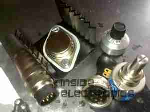
The parts arrived for my adjustable laser diode driver! Components here are an LM317K with heatsink, 100Ω 10-turn precision potentiometer, 15-turn counting dial & a 7-pin matching plug & socket.

Driver Schematic
Driver Schematic

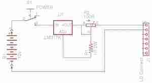
Here is the schematic for the driver circuit. I have used a 7-pin socket for provisions for active cooling of bigger laser diodes. R1 sets the maximum current to the laser diode, while R2 is the power adjustment. This is all fed from the main 12v Ni-Cd pack built into the PSU. The LM317 is set up as a constant current source in this circuit.

Installed
Installed

Here the power adjust dial & the laser head connector have been installed in the front panel. Power is switched to the driver with the toggle switch to the right of the connector.

Regulator
Regulator

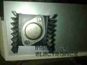
The LM317 installed on the rear panel of the PSU with it’s heatsink.

Connection
Connection

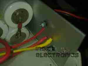
Connections to the regulator, the output is fully isolated from the heatsink & rear panel.

Posted on Leave a comment

Portable Power Supply

Battery
Battery

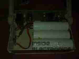
This is detailing my portable multi-purpose power pack of my own design. Here is an overview, mainly showing the 4Ah 12v Ni-Cd battery pack.

Front Panel Right
Front Panel Right

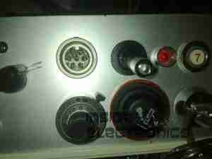
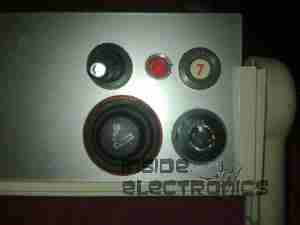
Panel Features – Bottom: Car cigar lighter socket, main power keyswitch. Top: LED toggle switch, provision for upcoming laser project, Red main Power LED, 7A circuit breaker.

Front Panel Left
Front Panel Left

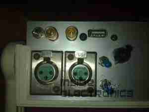
Top: Toggle switch serving post terminals, USB Port.
Post terminals supply unregulated 12v for external gadgets. USB port is standard 5v regulated for charging phones, PDAs etc.
Bottom: Pair of XLR connectors for external LED lights. Switches on their right control power & the knob controls brightness.

Additions are being made to this all the time, the latest being a 2W laser diode driver. Update to come soon!

Posted on Leave a comment

Chicom “500W” ATX PSU

Cover Removed
Cover Removed

Here is a cheapo 500W rated ATX PSU that has totally borked itself, probably due to the unit NOT actually being capable of 500W. All 3 of the switching transistors were shorted, causing the ensuing carnage:

AC Input
AC Input

Here is the AC input to the PCB. Note the vapourised element inside the input fuse on the left. There is no PFC/filtering built into this supply, being as cheap as it is links have been installed in place of the RFI chokes.

Input Side
Input Side

Main filter capacitors & bridge rectifier diodes. PCB shows signs of excessive heating.

Filter Caps Removed
Filter Caps Removed

Filter capacitors have been removed from the PCB here, showing some cooked components. Resistor & diode next to the heatsink are the in the biasing network for the main switching transistors.

Heatsinks Removed
Heatsinks Removed

Heatsink has been removed, note the remaining pin from one of the switching transistors still attached to the PCB & not the transistor 🙂

Transformers
Transformers

Output side of the PSU, with heatsink removed. Main transformer on  the right, transformers centre & left are the 5vSB  transformer & feedback transformer.

Output Side
Output Side

Output side of the unit, filter capacitors, choke & rectifier diodes are visible here attached to their heatsink.

Comparator
Comparator

Comparator IC that deals with regulation of the outputs & overvoltage protection.

Posted on Leave a comment

PSP Slim

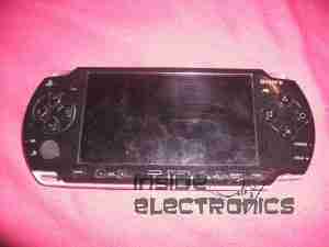
Front
Front

Here is a PSP Slim that recently died.

Label
Label

For those that are interested, here is the ID label, this is a PSP-2003.

Front Removed
Front Removed

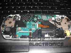
Here the front of the unit has been removed, showing the first internal components.

Screen Removed
Screen Removed

Here is the unit with the LCD removed, here the mainboard is partially visible.

Left Pad
Left Pad

Left pad unit removed from the PSP, with the left speaker & the memory stick slot cover.

Left Pad Rear
Left Pad Rear

Rear of the left pad assembly, showing the speaker.

Joypad
Joypad

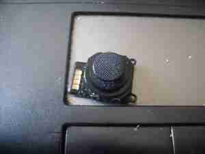
Joypad removed from the casing. Resistive unit.

Output Jack
Output Jack

Headphone/data board removed from the casing. This also has TV-Out on the PSP-200x series.

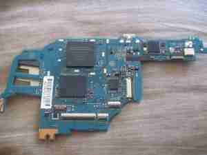
Mainboard
Mainboard

Mainboard removed. Main CPU is at the top. Sockets around the bottom connect to the UMD drive & UMD Drive.

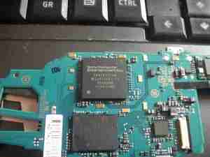
CPU & GPU
CPU & GPU

Closeup of the main chipset. CPU is the top IC.

Mainboard Rear
Mainboard Rear

Rear of the mainboard, Memory Stick socket on the right.

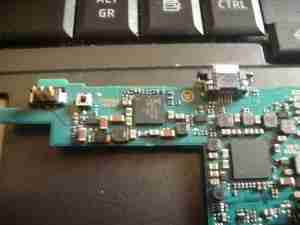
WiFi Chipset
WiFi Chipset

Closeup of the WiFi chipset & the charging power socket on the right.

Charging Chipset
Charging Chipset

Closeup of the bettery connector & the charge controller IC.

UMD Drive
UMD Drive

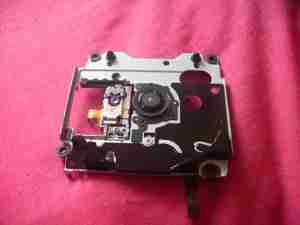
UMD Drive removed from the rear of the casing. This is a miniature DVD style drive, using a 635nm visible red laser.

UMD Drive Back
UMD Drive Back

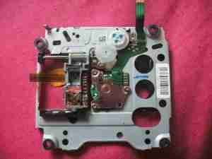
Rear of the UMD drive, showing the laser sled & drive motors. Both the spindle motor & the sled motor are 3-phase brushless type. The laser diode/photodiode array is at the top of the laser sled.

Posted on Leave a comment

Southwestern Bell Freedom Phone

Phone
Phone

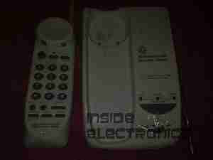
This is an old cordless landline phone, with dead handset batteries.

Handset Radio Board
Handset Radio Board

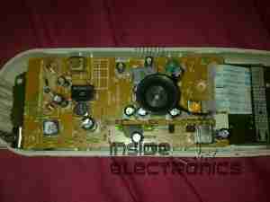
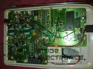
Here’s the handset with the back removed. Shown is the radio TX/RX board, underneath is the keyboard PCB with the speaker & mic. All the FM radio tuning coils are visible & a LT450GW electromechanical filter.

Handset Radio Board Bottom

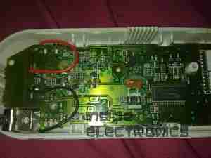
Radio PCB removed from the housing showing the main CPU controlling the unit, a Motorola MC13109FB.

Keypad Board
Keypad Board

The keypad PCB, with also holds the microphone & speaker.

Handset Keypad Board Bottom

Bottom of the keypad board, which holds a LSC526534DW 8-Bit µC & a AT93C46R serial EEPROM for phone number storage.

Base Main Board
Base Main Board

Here’s the base unit with it’s top cover removed. Black square object on far right of image is the microphone for intercom use, power supply section is top left, phone interface bottom left, FM radio is centre. Battery snap for power backup is bottom right.

Power Supply Section

PSU section of the board on the left here, 9v AC input socket at the bottom, with bridge rectifier diodes & main filter capacitor above. Two green transformers on the right are for audio impedance matching. Another LT450GW filter is visible at the top, part of the base unit FM transceiver.

ICs
ICs

Another 8-bit µC, this time a LSC526535P, paired with another AT93C46 EEPROM. Blue blob is 3.58MHz crystal resonator for the MCU clock. The SEC IC is a KS58015 4-bit binary to DTMF dialer IC. This is controlled by the µC.

Base Main Board Bottom

Underside of the base unit Main PCB, showing the matching MC13109FB IC for the radio functions.

Posted on Leave a comment

Hair Dryer

Housing
Housing

This is a 1500W hairdryer, death caused by thermal switch failure.

Switch
Switch

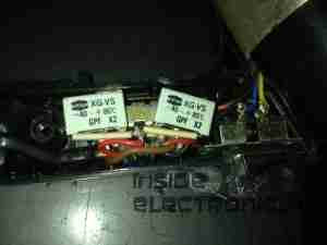
This is the switch unit. Attached are two suppression capacitors & a blocking diode. Cold switch is on right.

Heating Element
Heating Element

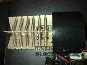
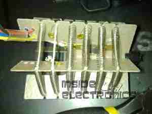
Heating element unit removed from housing. Coils of Nichrome wire heat the air passing through the dryer. Fan unit is on right.

Thermal Switch
Thermal Switch

Other side of the heating element unit, here can be seen the thermal switch behind the element winding. (Black square object).

Fan Motor
Fan Motor

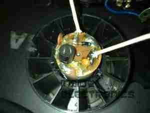
The fan motor in this dryer is a low voltage DC unit, powered through a resistor formed by part of the heating element to drop the voltage to around 12-24v. Mounted on the back of the motor here is a rectifier assembly. Guide vanes are visible around the motor, to straighten the airflow from the fan blades.

Fan
Fan

5-blade fan forces air through the element at high speed. Designed to rotate at around 13,000RPM.