Since I seem to be the local go-to for any dead electrical equipment, this brand-new Silverline polisher has landed on my desk. Purchased cheap from an auction this was dead on arrival. Checking the fuse revealed nothing suspect, so a quick teardown to find the fault was required.
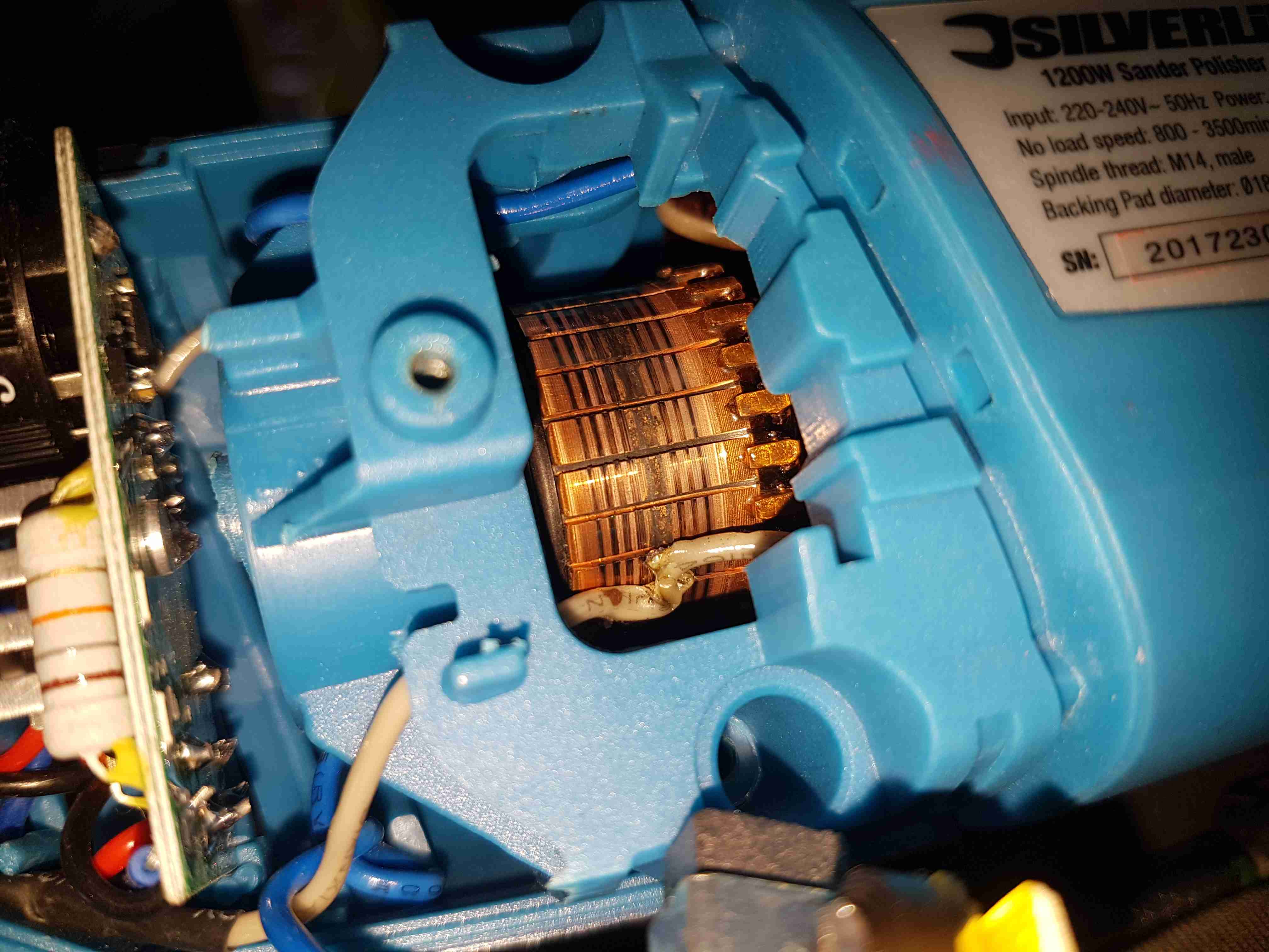
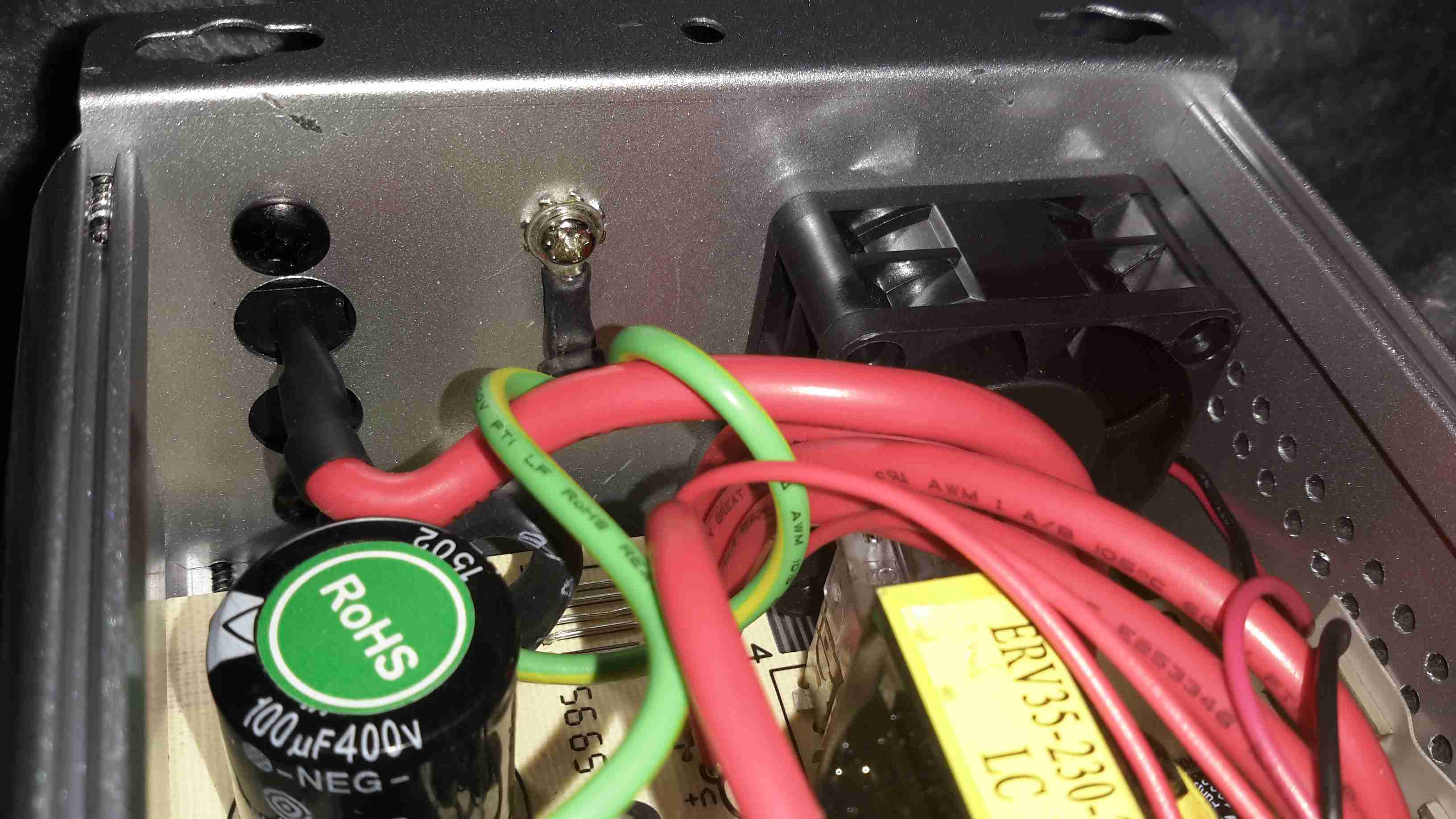
Above is a photo of the commutator with the brush holder removed, and the source of the issue. The connection onto the field winding of the universal motor has been left unsecured, as a result it’s managed to move into contact with the commutator.
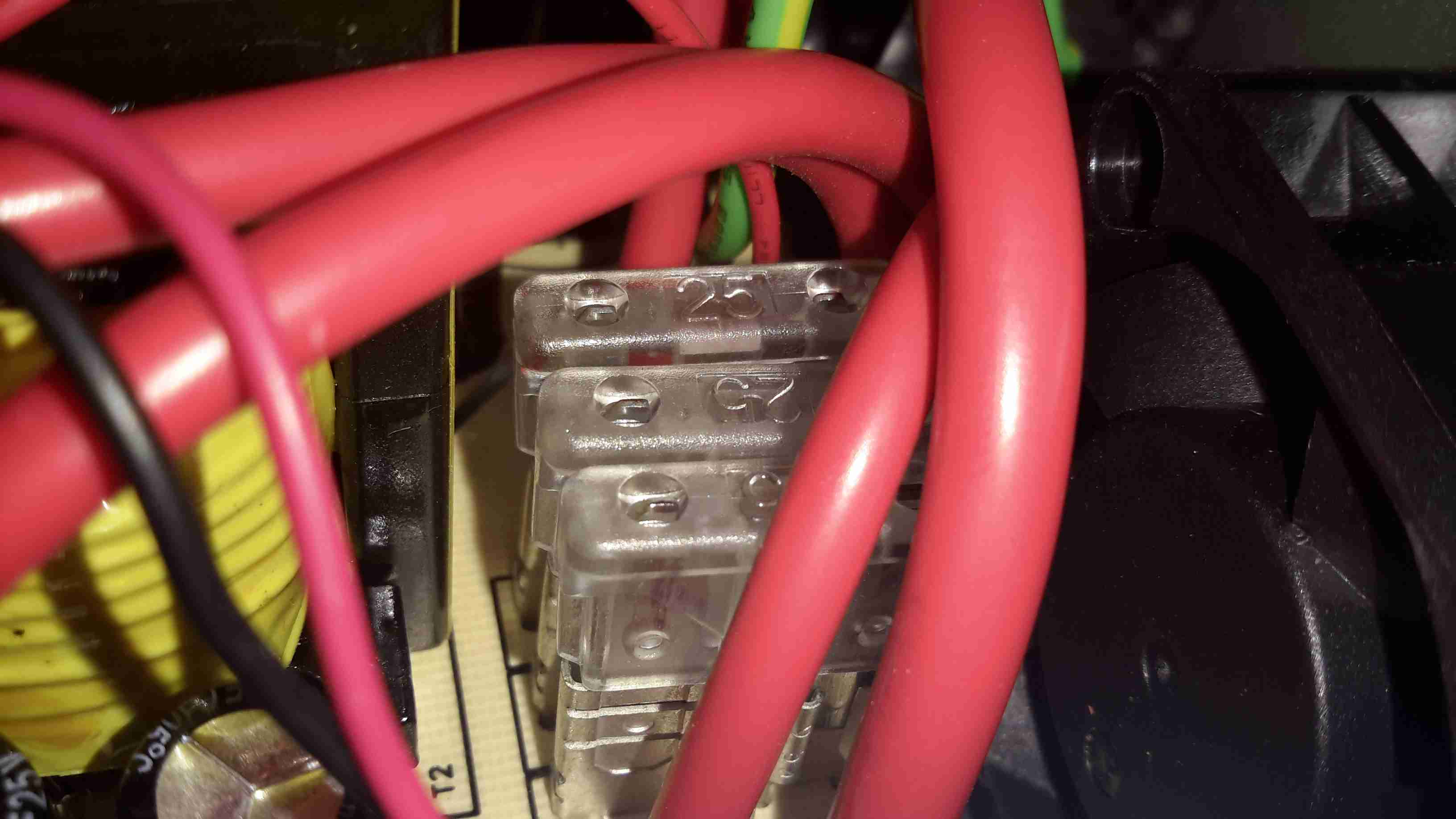
This has done a pretty good job of chewing it’s way through the wire entirely. There is some minor damage to the commutator segments, but it’s still smooth, and shouldn’t damage the brushes.
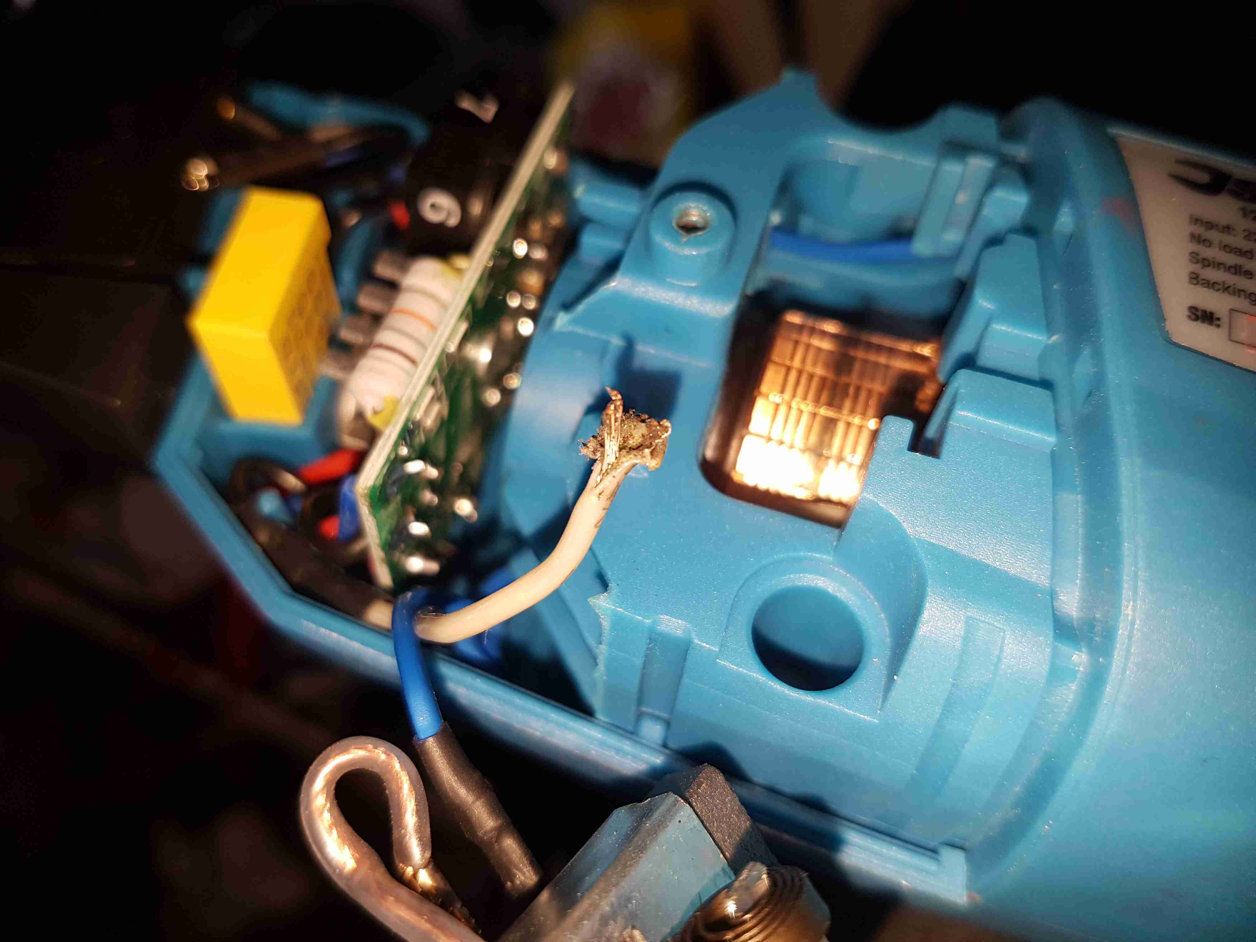
Chewed Wire
A quick pull on what’s left of the wire reveals the extent of the problem. It’s entirely burned through! Unfortunately the stator assembly with the field windings is pressed into the plastic housing, so it’s not removable. An in-place solder joint was required to the very short remains of the wire inside the housing. Once this was done the polisher sprang to life immediately, with no other damage.
This unit probably ended up at an auction as a factory reject, or a customer return to a retail outlet. If the latter, I would seriously question the quality control procedures of Silverline tools. 😉
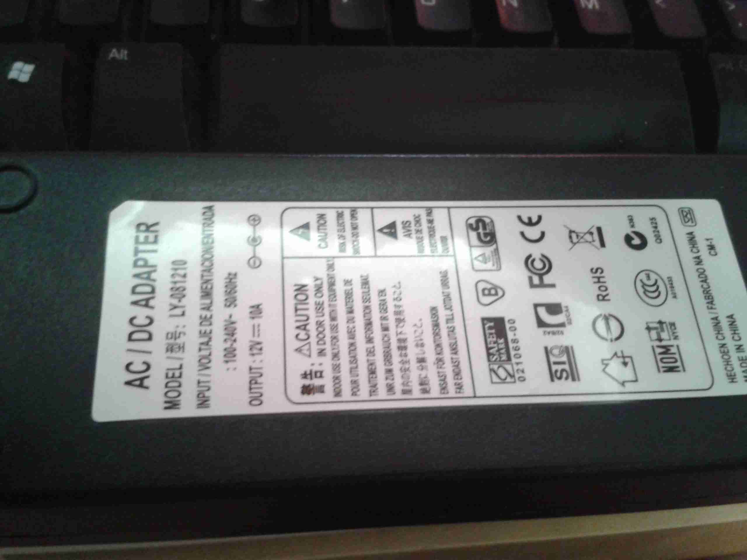
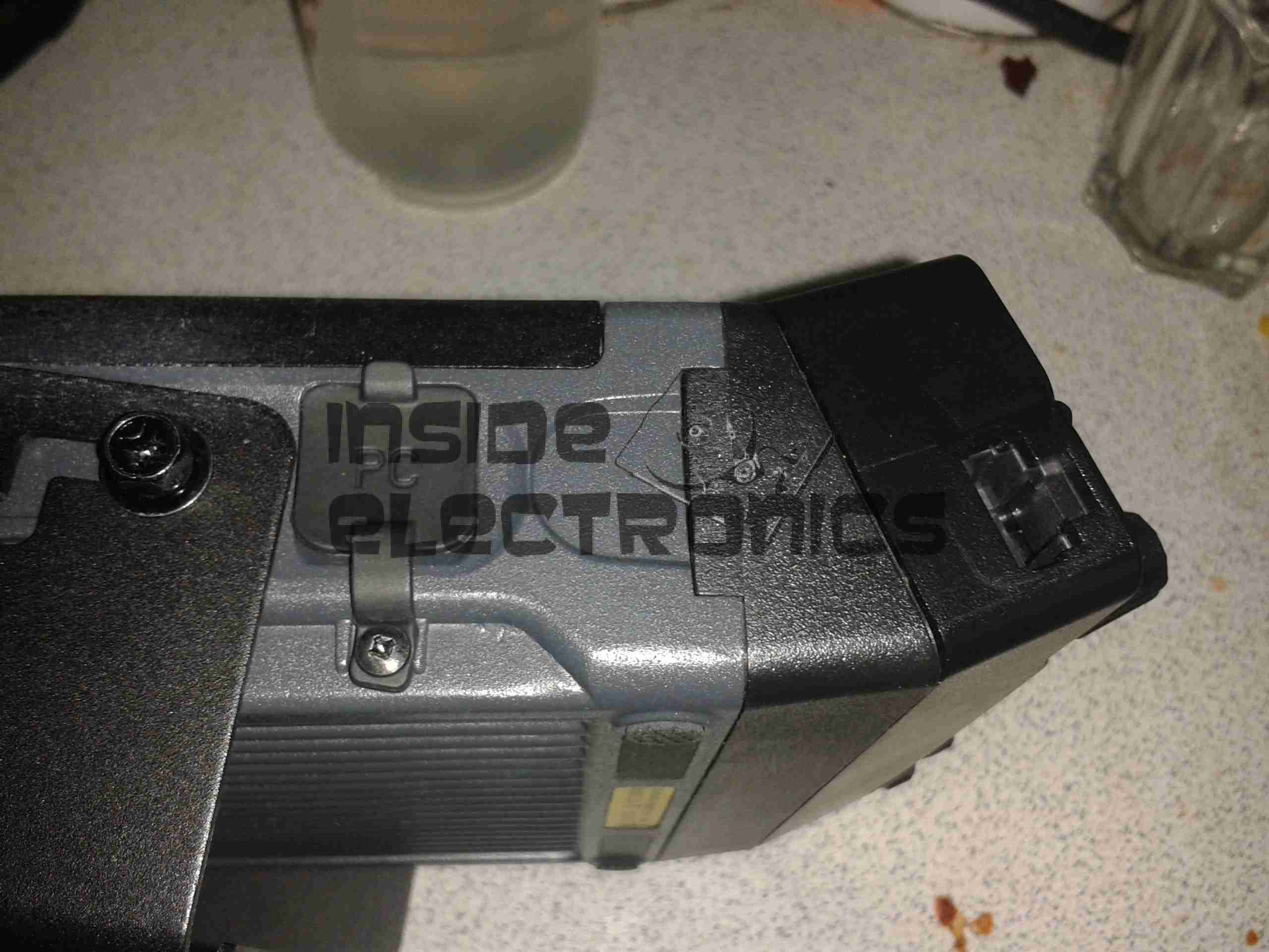
The rear has the specifications, laser-marked into the plastic. The serial numbers are just sticky labels though, and will come off easily with use.
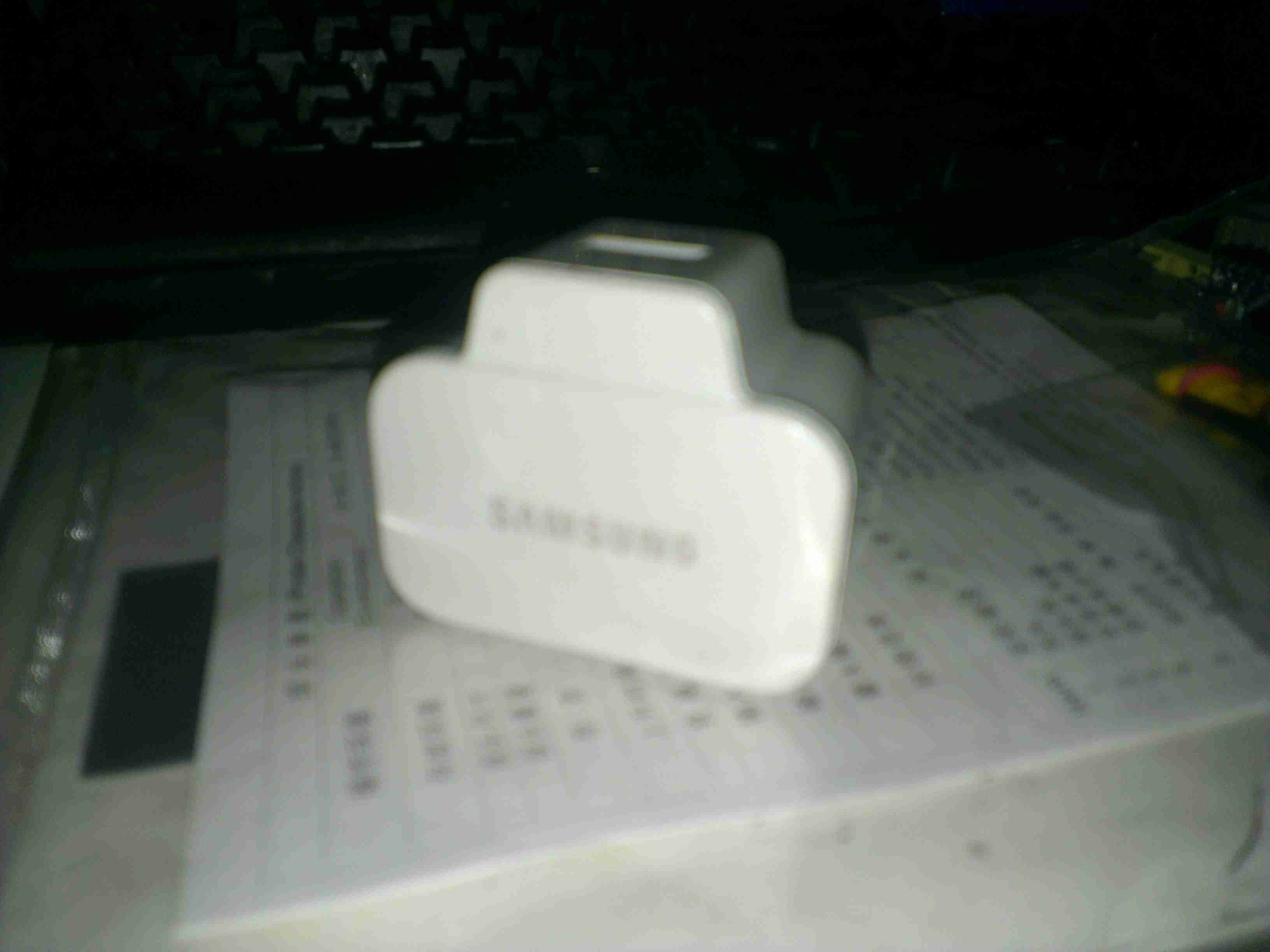
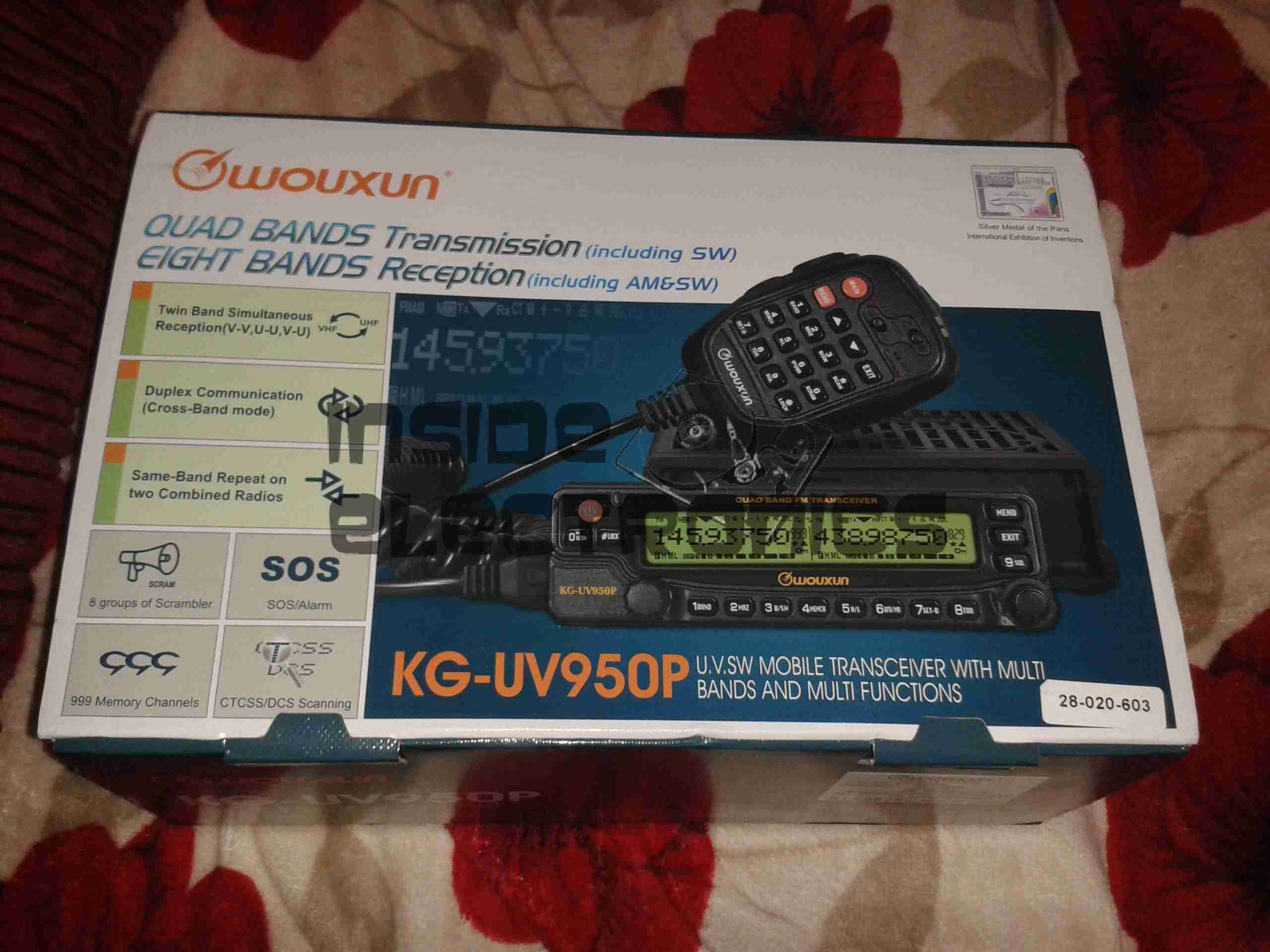
Contec CMS-50F
This is the Contec CMS-50F wrist-mounted pulse oximeter unit, which has the capability to record data continuously to onboard memory, to be read out at a later time via a USB-Serial link. There is software supplied with the unit for this purpose, although it suffers from the usual Chinese quality problems. The hardware of this unit is rather well made, the firmware has some niggles but is otherwise fully functional, however the PC software looks completely rushed, is of low quality & just has enough functionality to kind-of pass as usable.
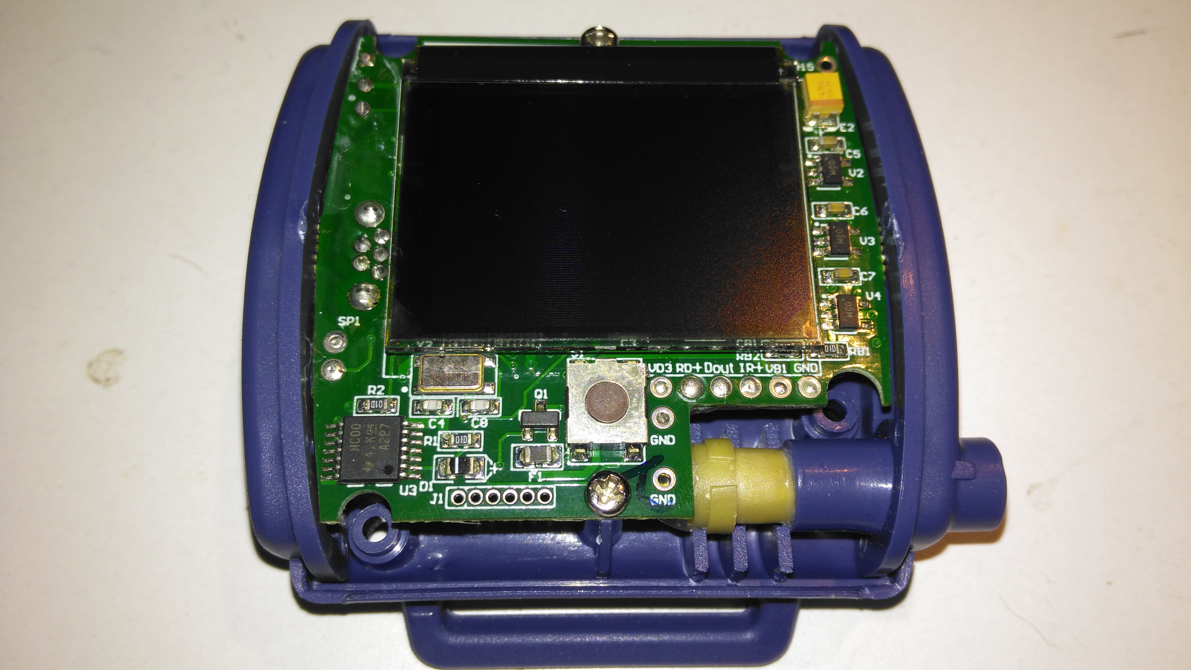
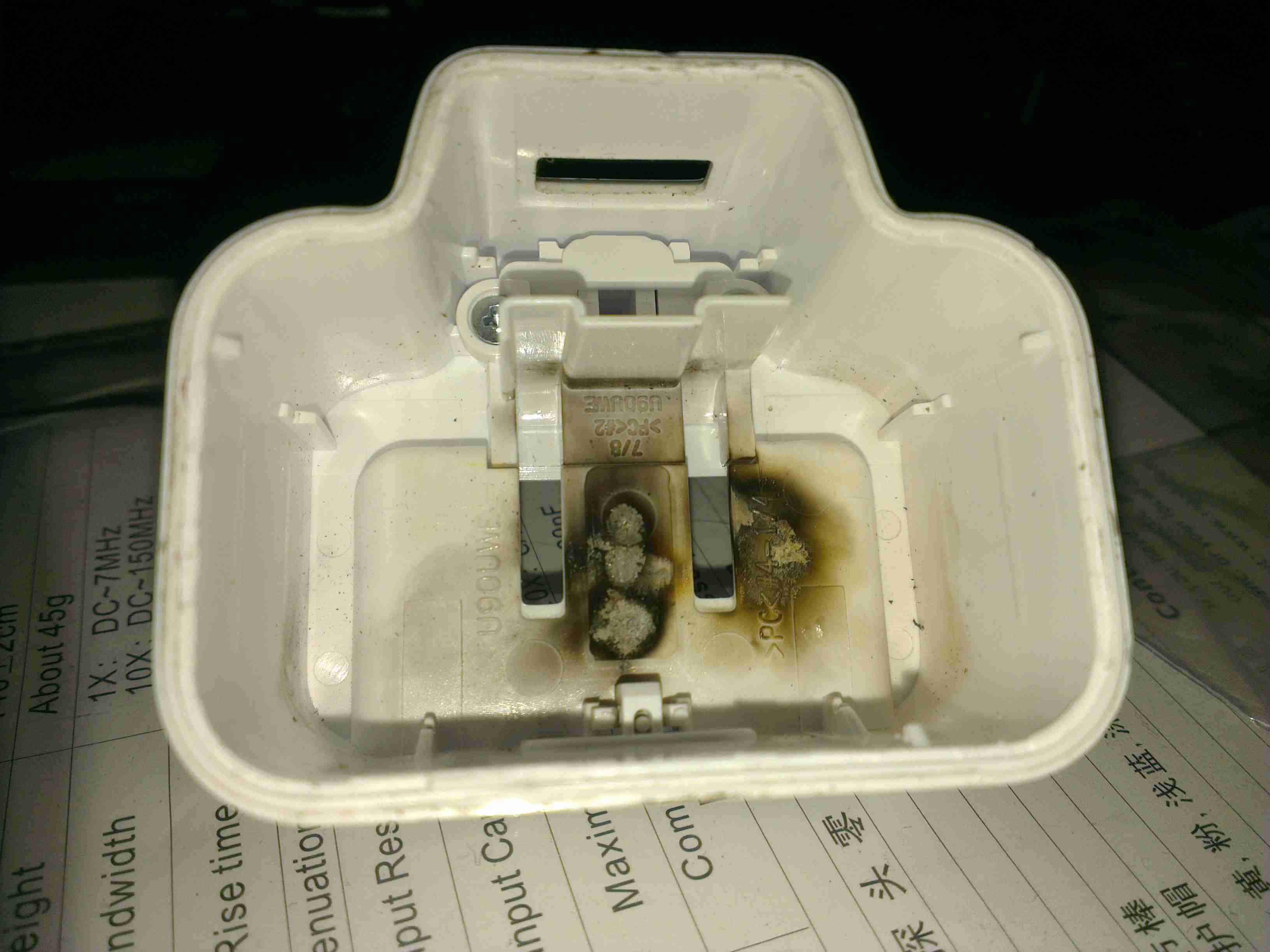
Top Cover Removed
A total of 4 screws hold the casing together, once these are removed the top comes off. The large colour OLED display covers nearly all of the board here. The single button below is the user interface. The connection to the probe is made via the Lemo-style connector on the lower right.
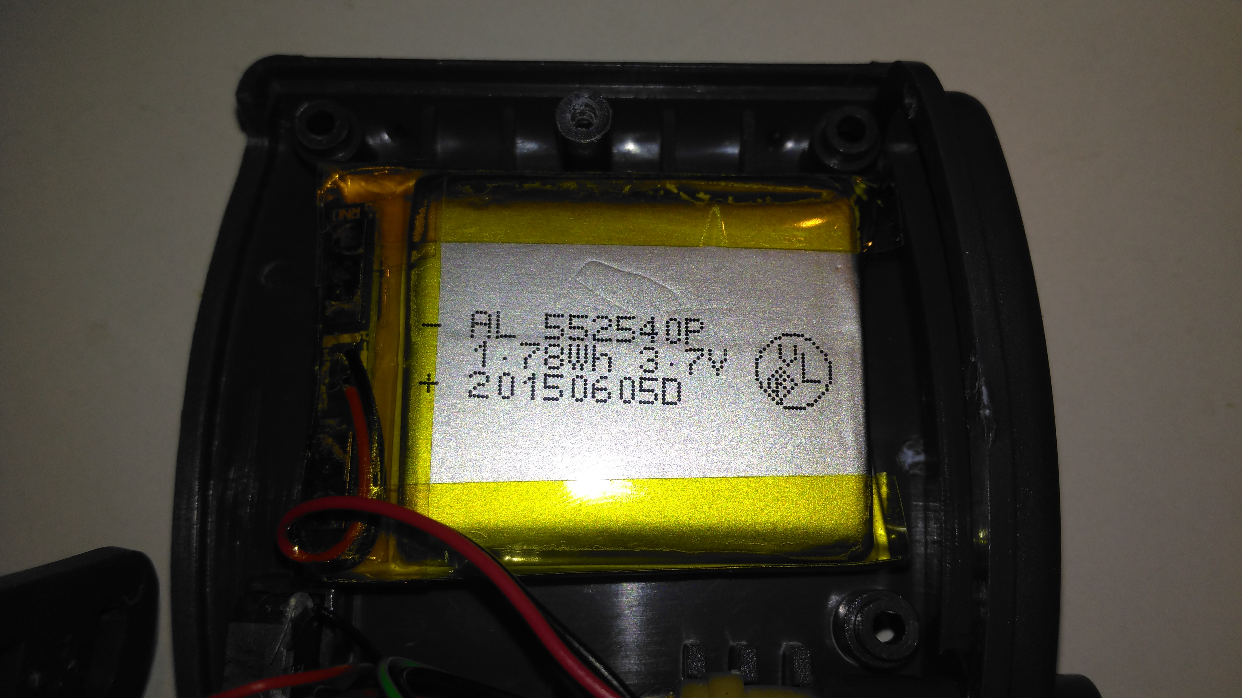
Lithium Cell
Power is provided by a relatively large lithium-ion cell, rated at 1.78Wh.
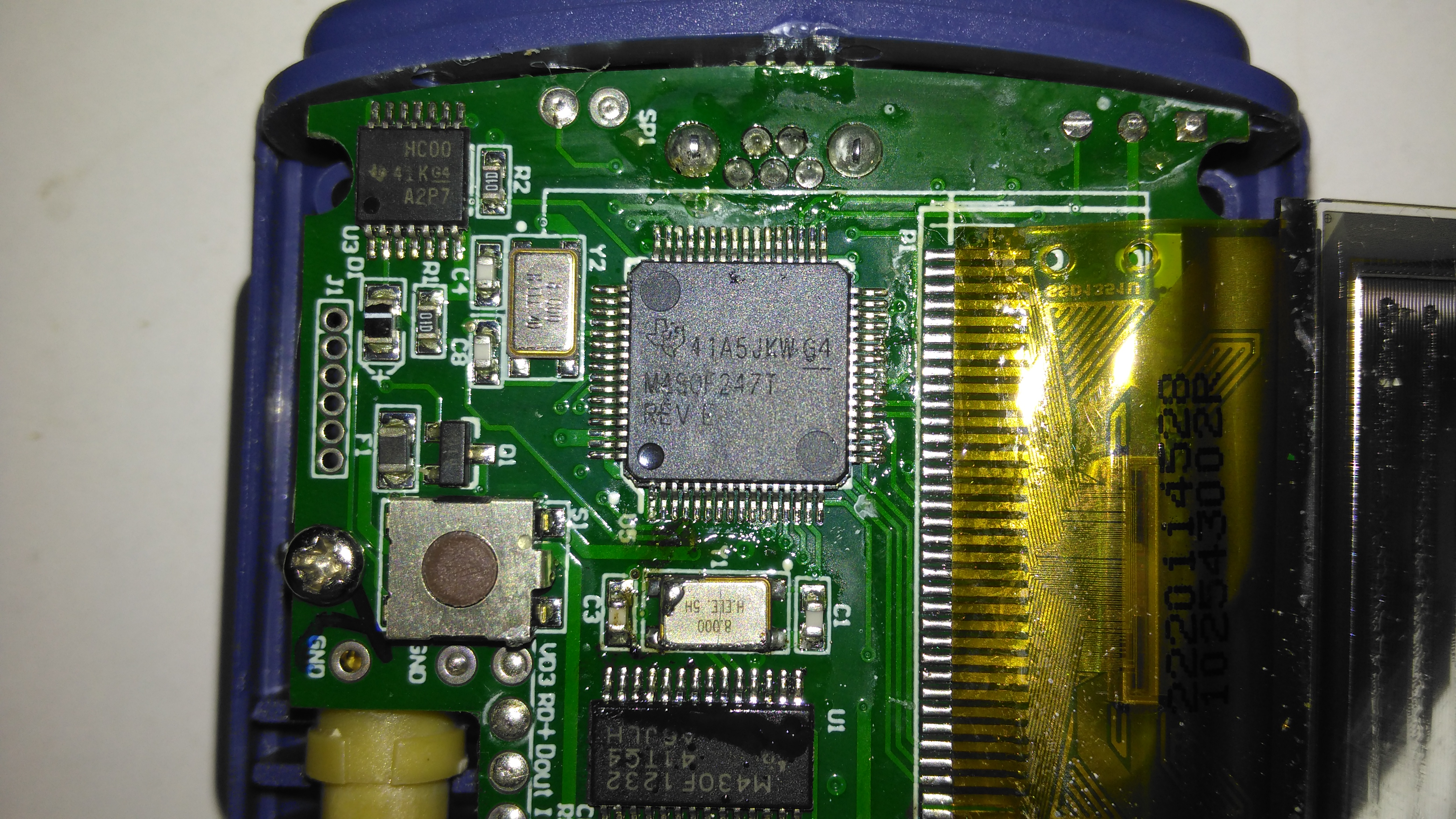
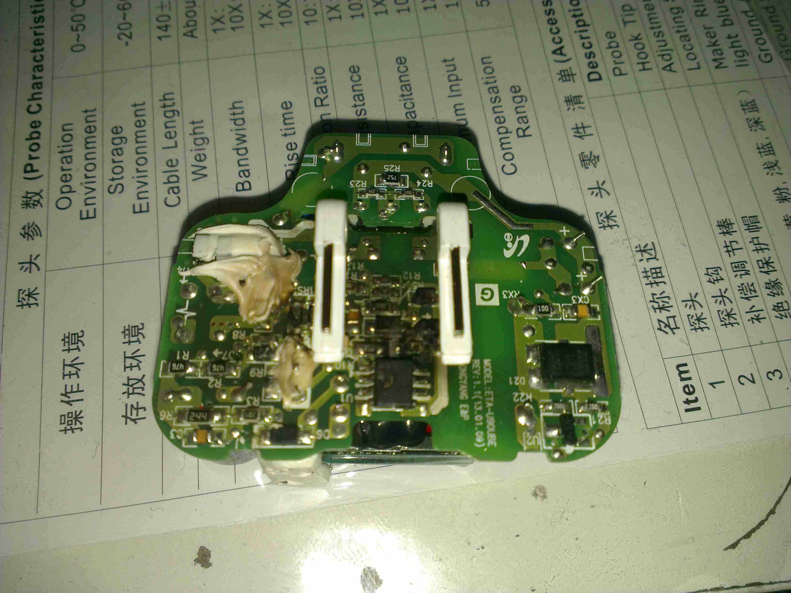
Main Processor
All the heavy lifting work of the LCD, serial comms, etc are handled by this large Texas Instruments microcontroller, a MSP430F247. The clock crystal is just to the left, with the programming pins. I’m not sure of the purpose of the small IC in the top left corner, I couldn’t find any reference to the markings.
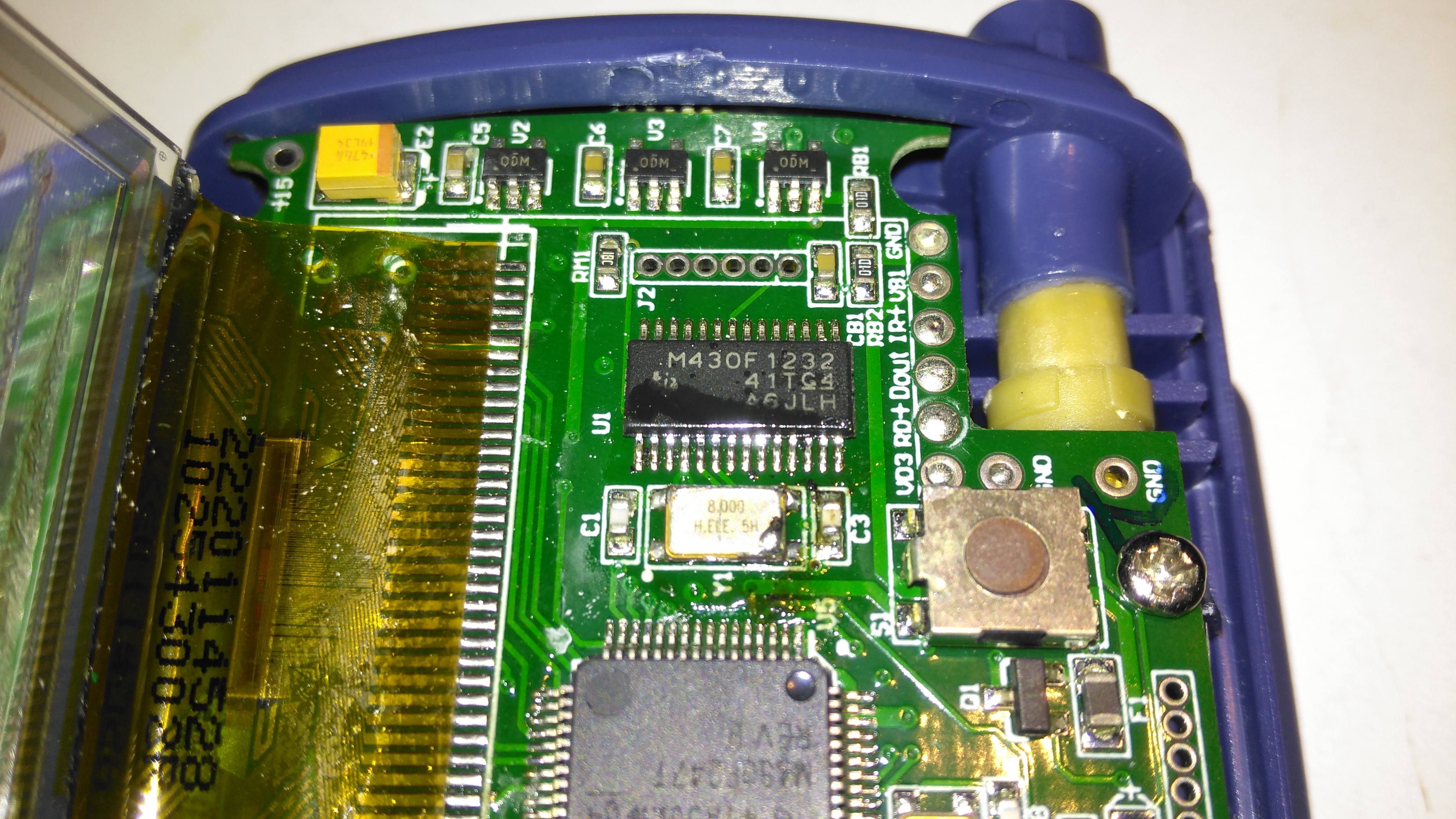
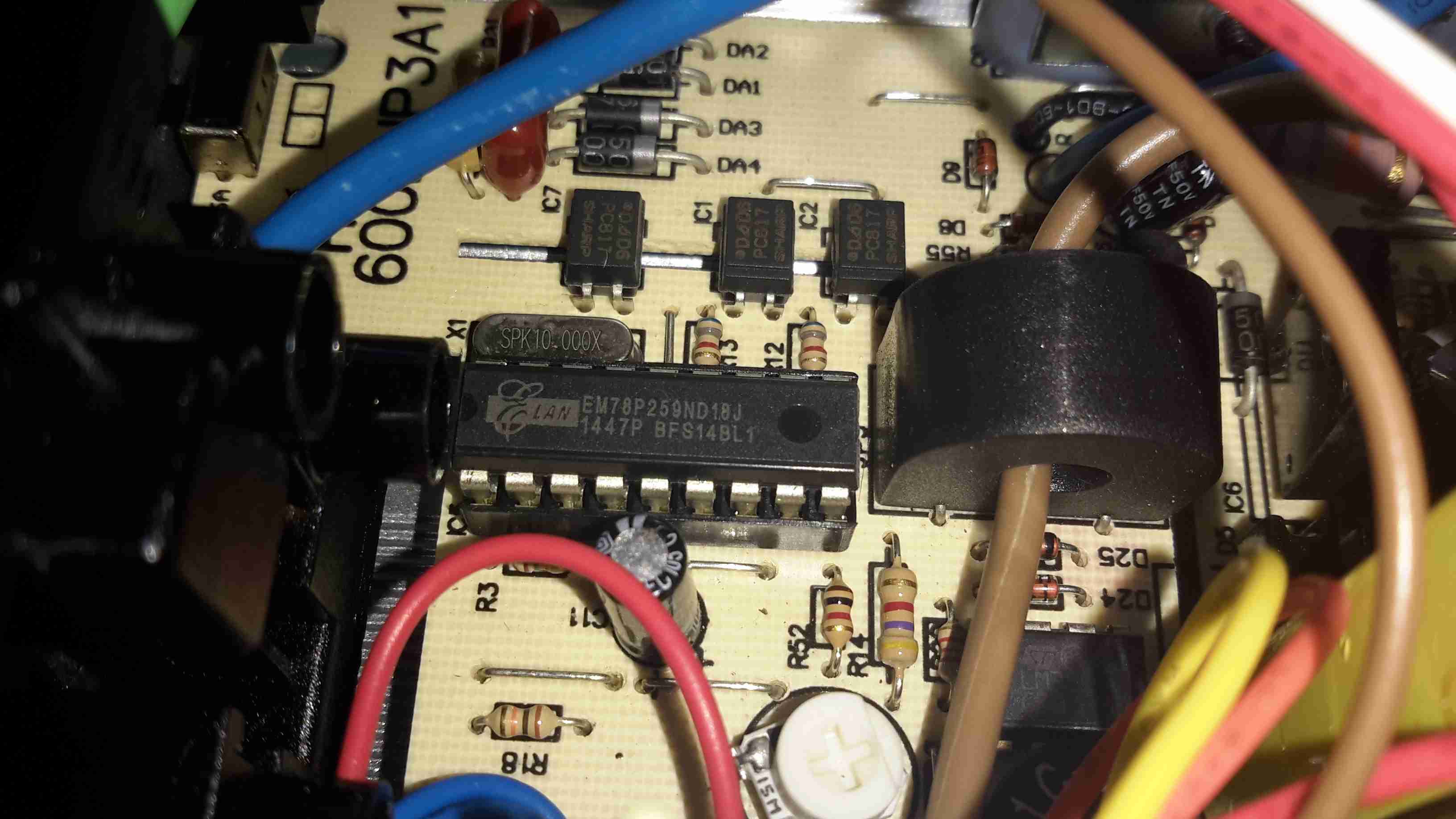
Aux Processor
The actual pulse oximetry sensor readings seem to be dealth with by a secondary microcontroller, a Texas Instruments M430F1232 Mixed-Signal micro. This has it’s own clock crystal just underneath. The connections to the probe socket are to the right of this µC, while the programming bus is broken out to vias just above. The final devices on this side of the board are 3 linear regulators, supplying the rails to run all the logic in this device.
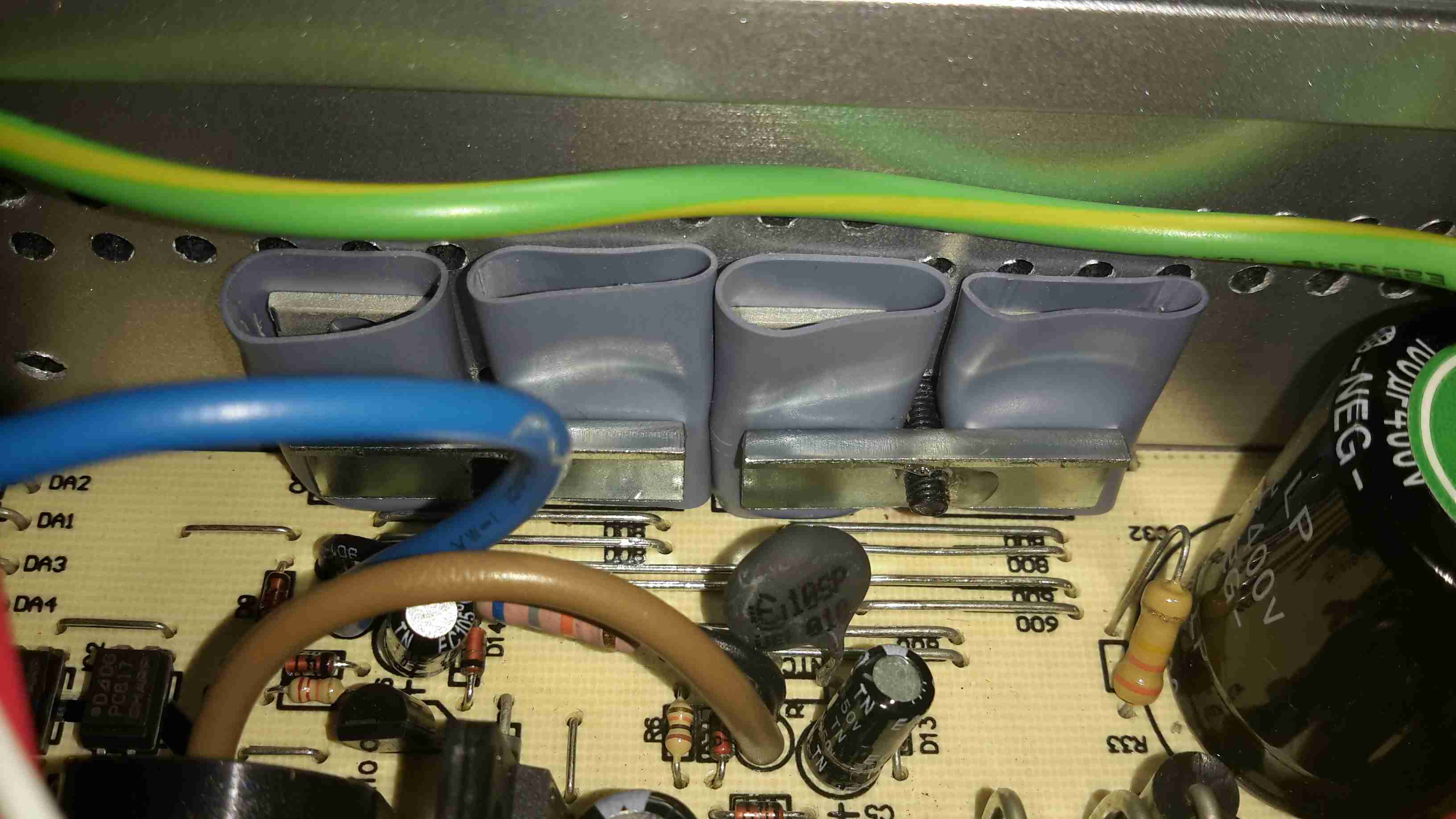
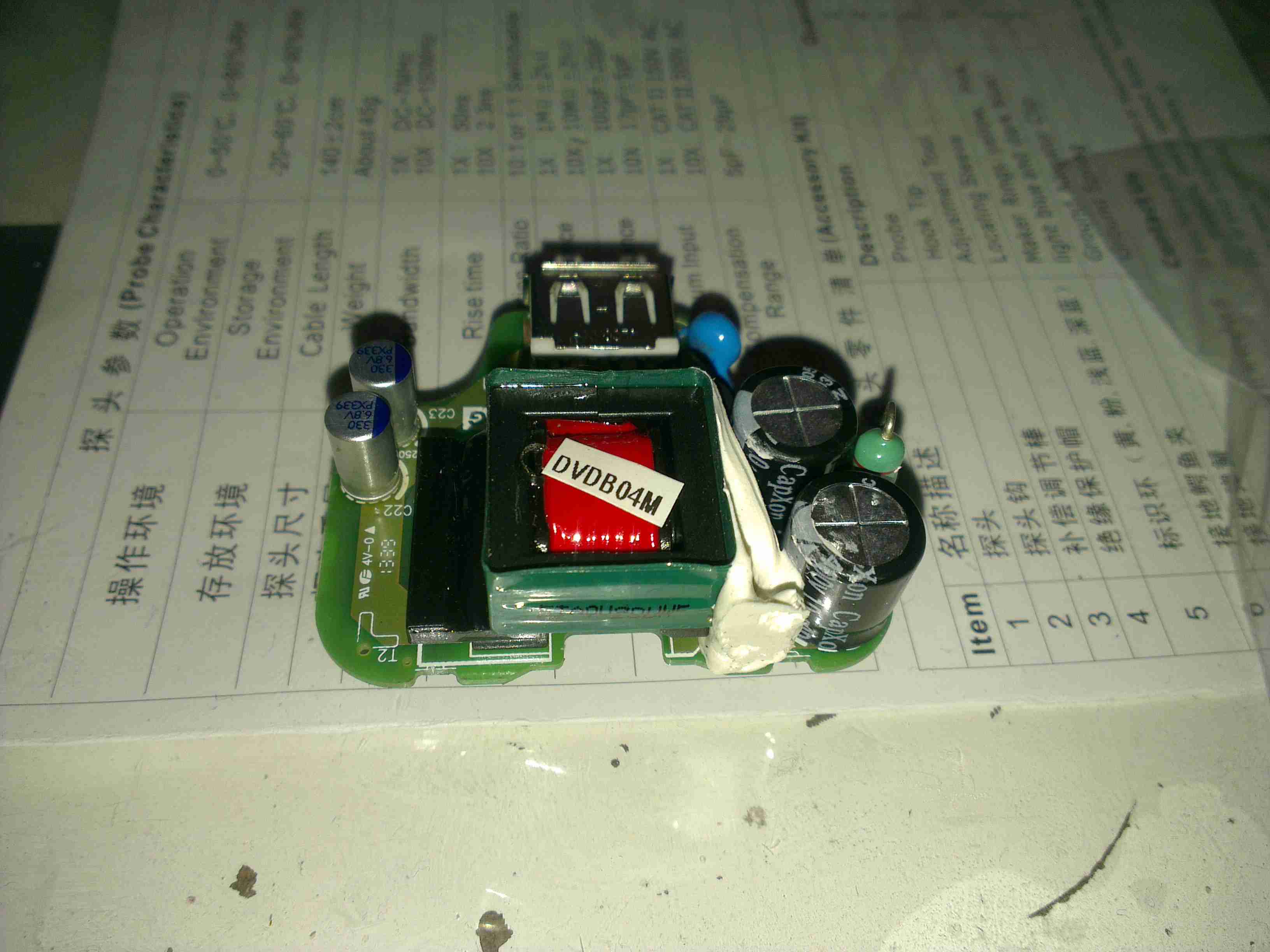
Main PCB Rear
The rear of the PCB has the SiLabs CL2102 USB-Serial interface IC, the large Winbond 25X40CLNIG 512KByte SPI flash for recording oximetry data, and some of the power support components. The RTC crystal is also located here at the top of the board. Up in the top left corner is a Texas Instruments TPS61041 Boost converter, with it’s associated components. This is probably supplying the main voltage for the OLED display module.
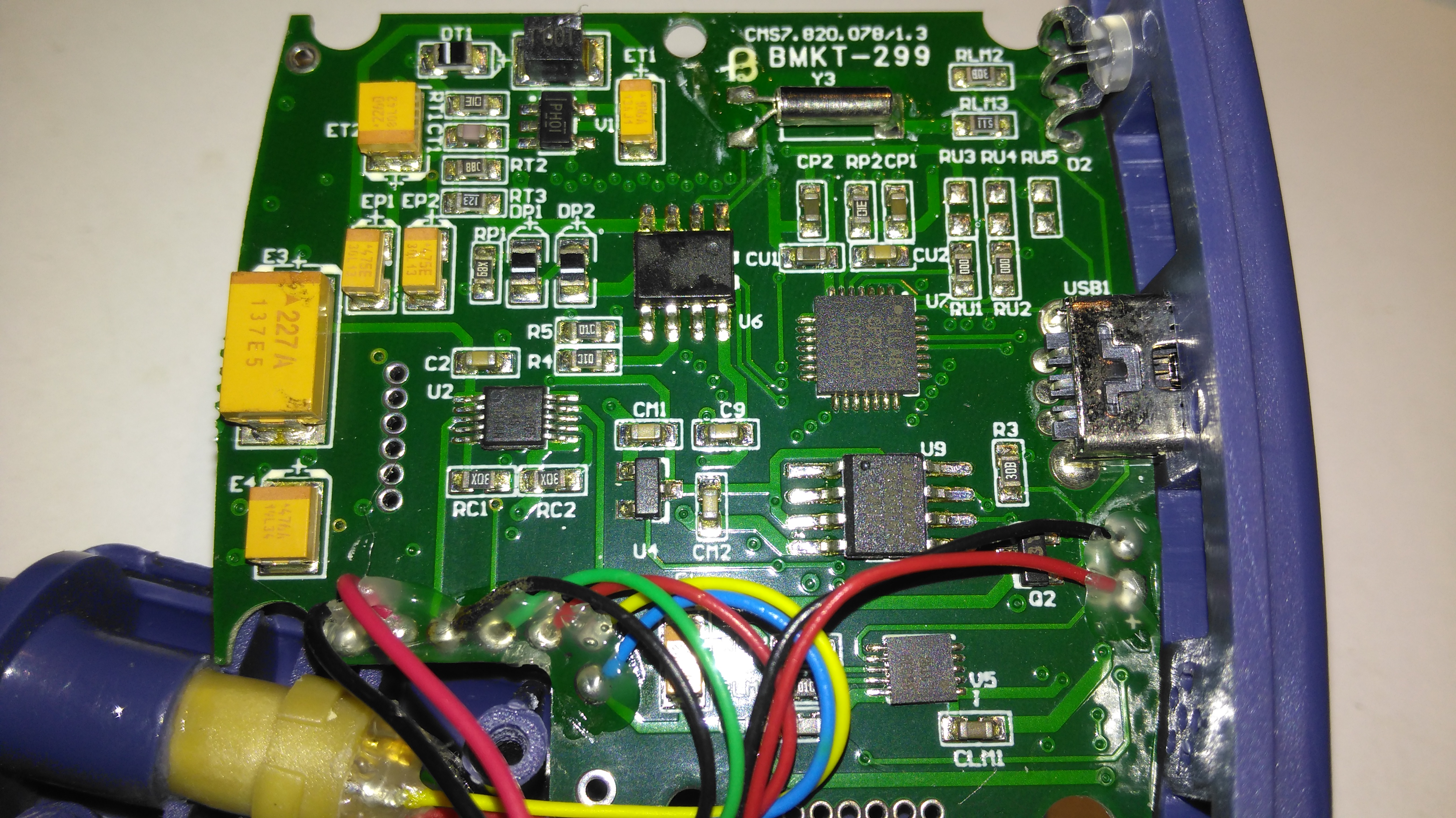
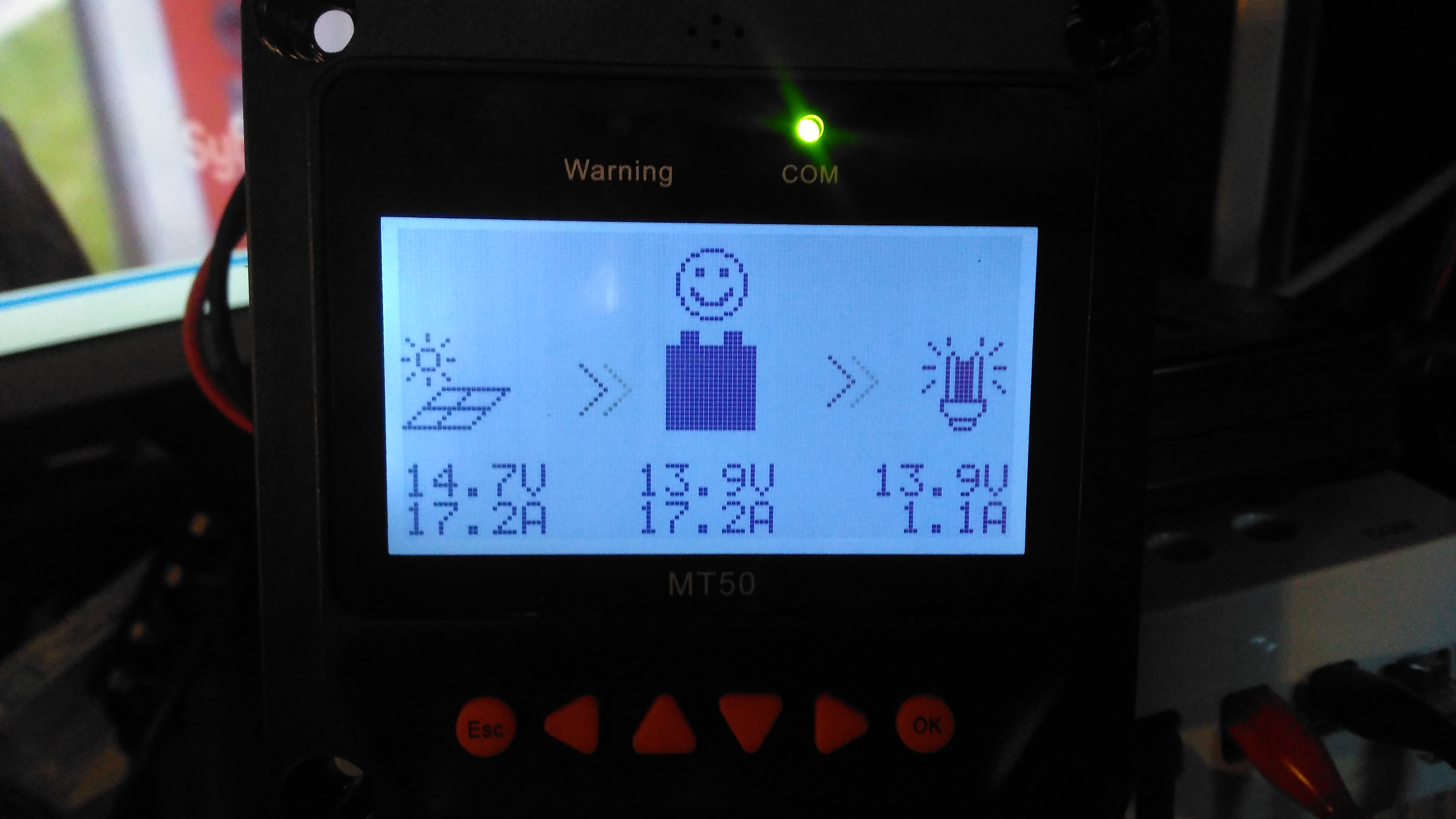
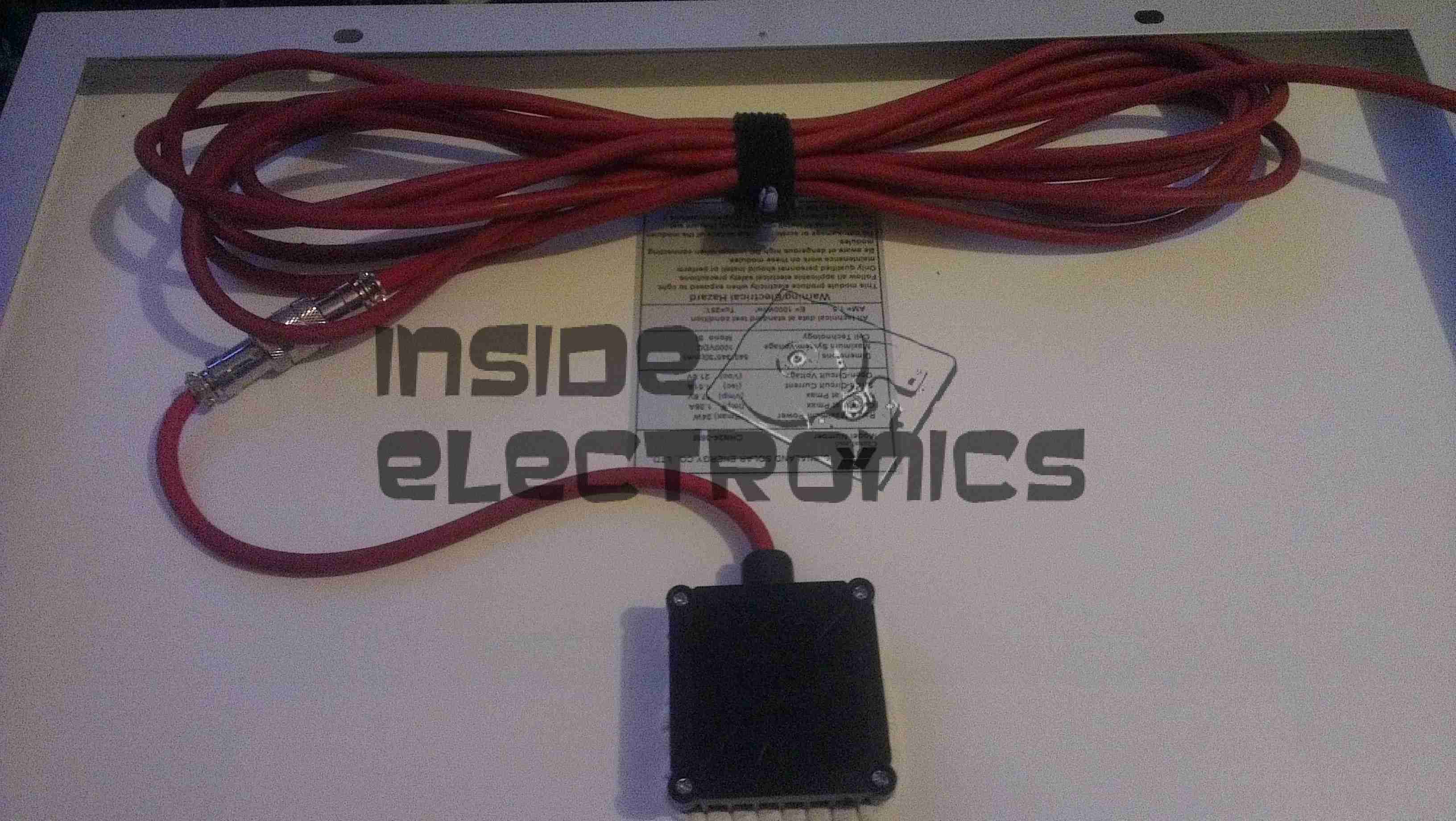
Here’s the MT50 controller from EpEver, that interfaces with it’s Tracer MPPT solar charge controllers, and gives access to more programming options on the charge controllers, without the need for a laptop. The display is a large dot-matrix unit, with built in backlight. Above is the display on the default page, showing power information for the entire system.
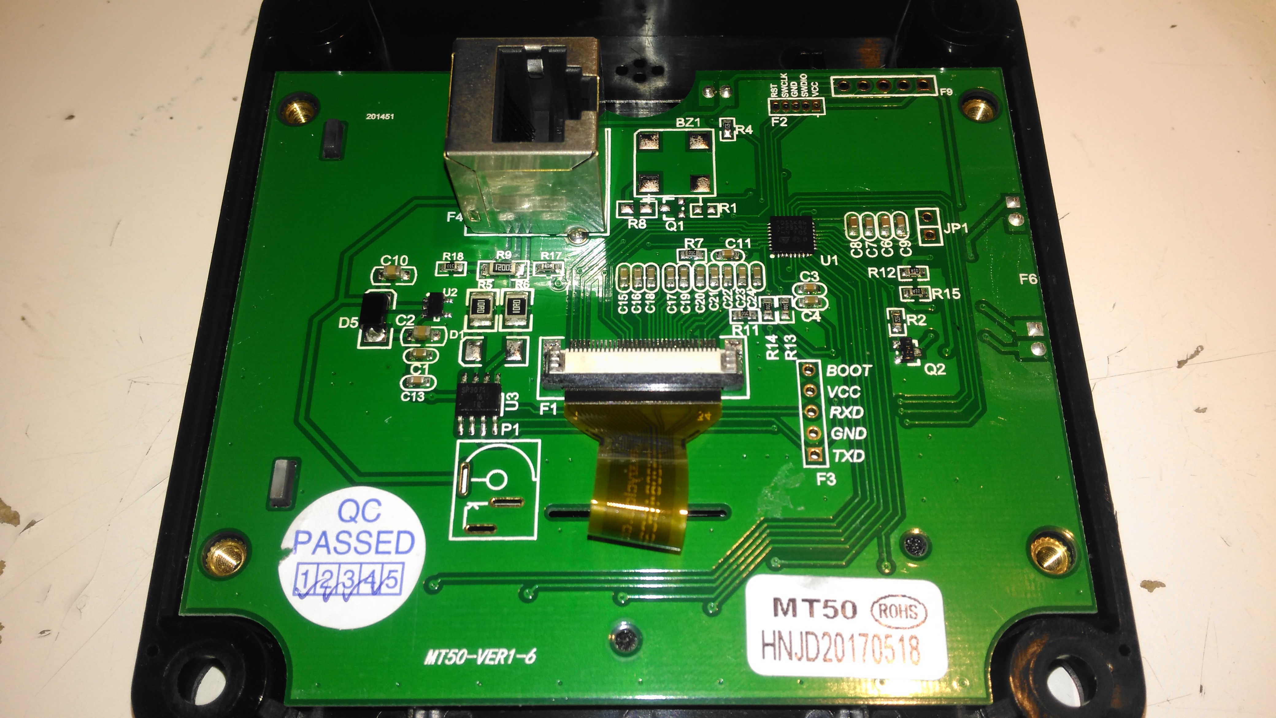
PCB Rear
The rear plastic cover is held in place by 4 machine screws, which thread into brass inserts in the plastic frame – nice high quality touch on the design here, no cheap self tapping plastic screws. Both power & data arrive via an Ethernet cable, but the communication here is RS-485, and not compatible with Ethernet! The PCB is pretty sparse, with comms & power on the left, LCD connection in the centre, and the microcontroller on the right.
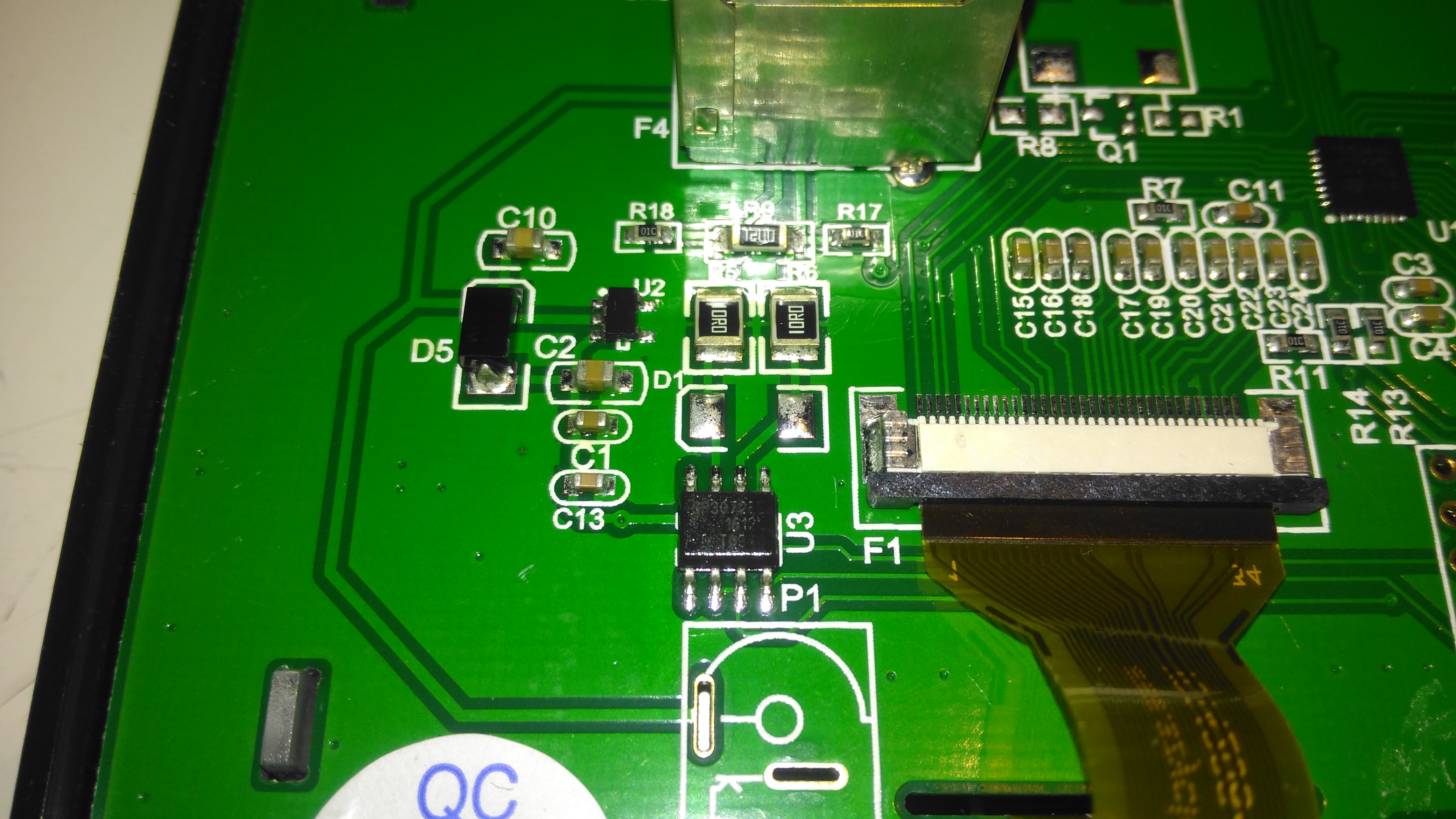
RS-485 Transceiver
On the left of the board is the RS0485 transceiver, and a small voltage regulator. There’s also a spot for a DC barrel jack, which isn’t included in this model for local power supply.
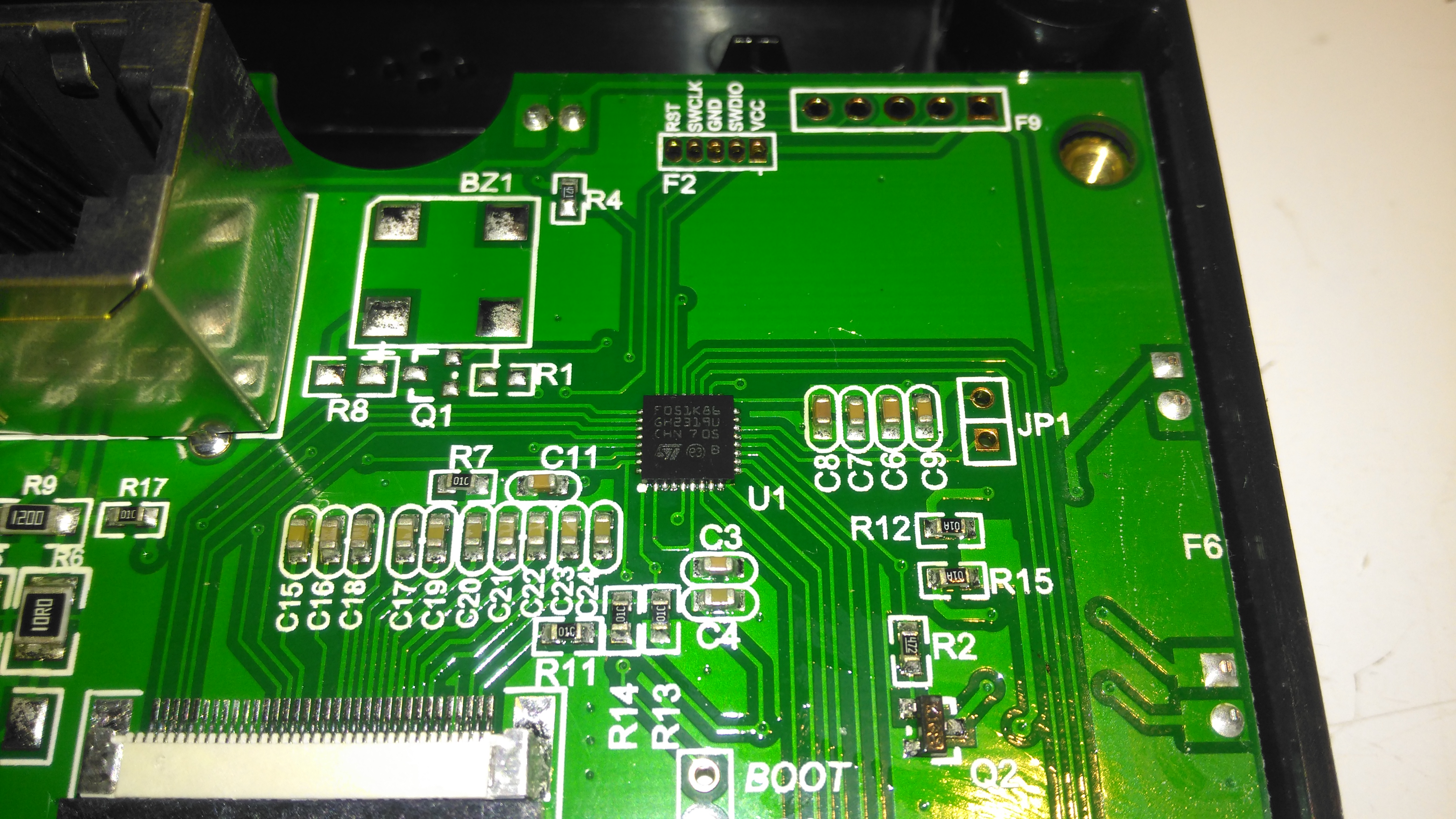
STM32 Microcontroller
The other side of the board holds the main microcontroller which communicates with the charge controller. This is a STM32F051K8 from ST Microelectronics. With a 48MHz ARM Cortex M0 core, and up to 64K of flash, this is a pretty powerful MCU that has very little to do in this application.
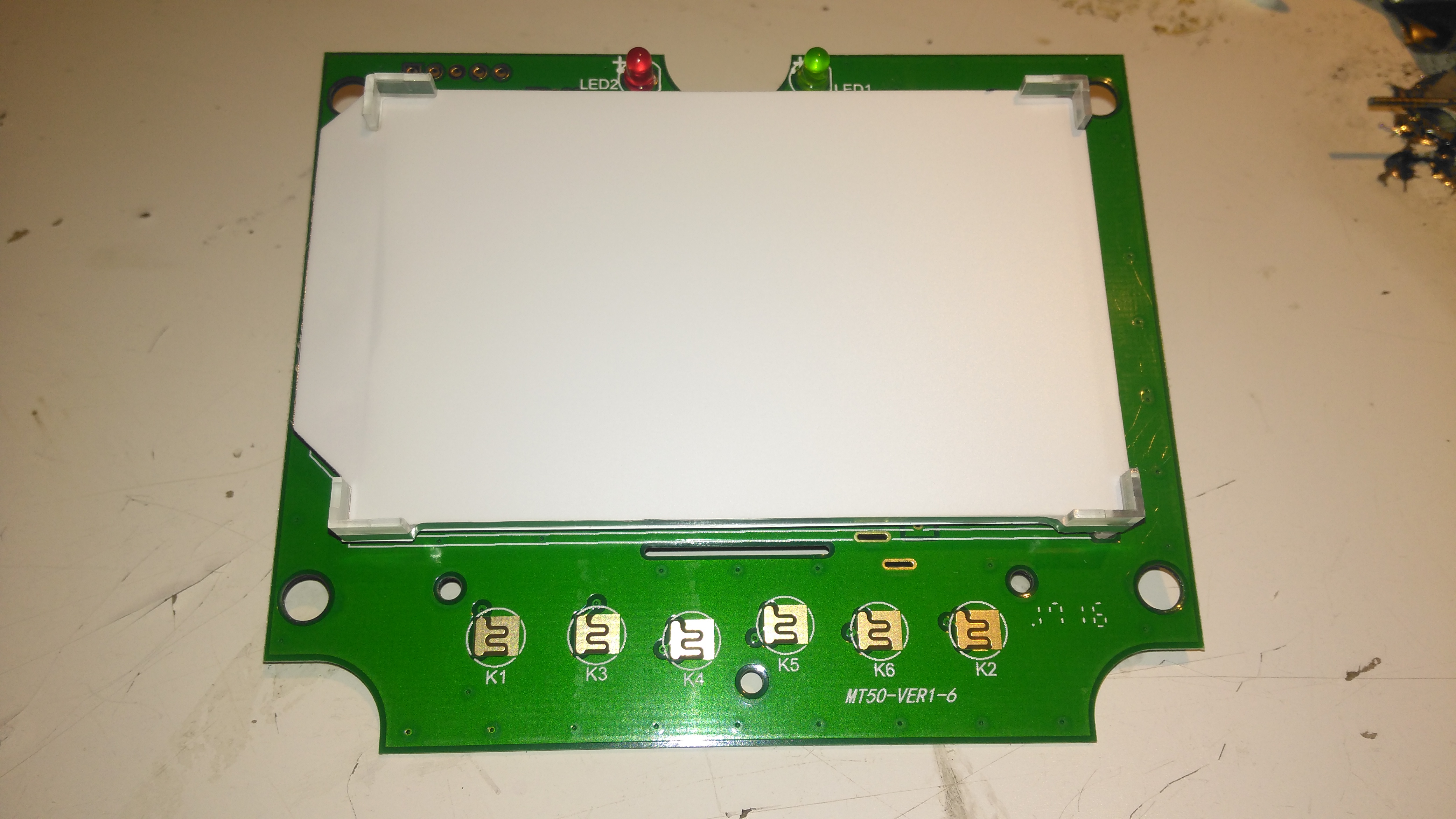
PCB Front
The front of the PCB has the ENIG contacts of the front panel buttons, and the LCD backlight assembly. There’s nothing else under the plastic backlight spreader either.
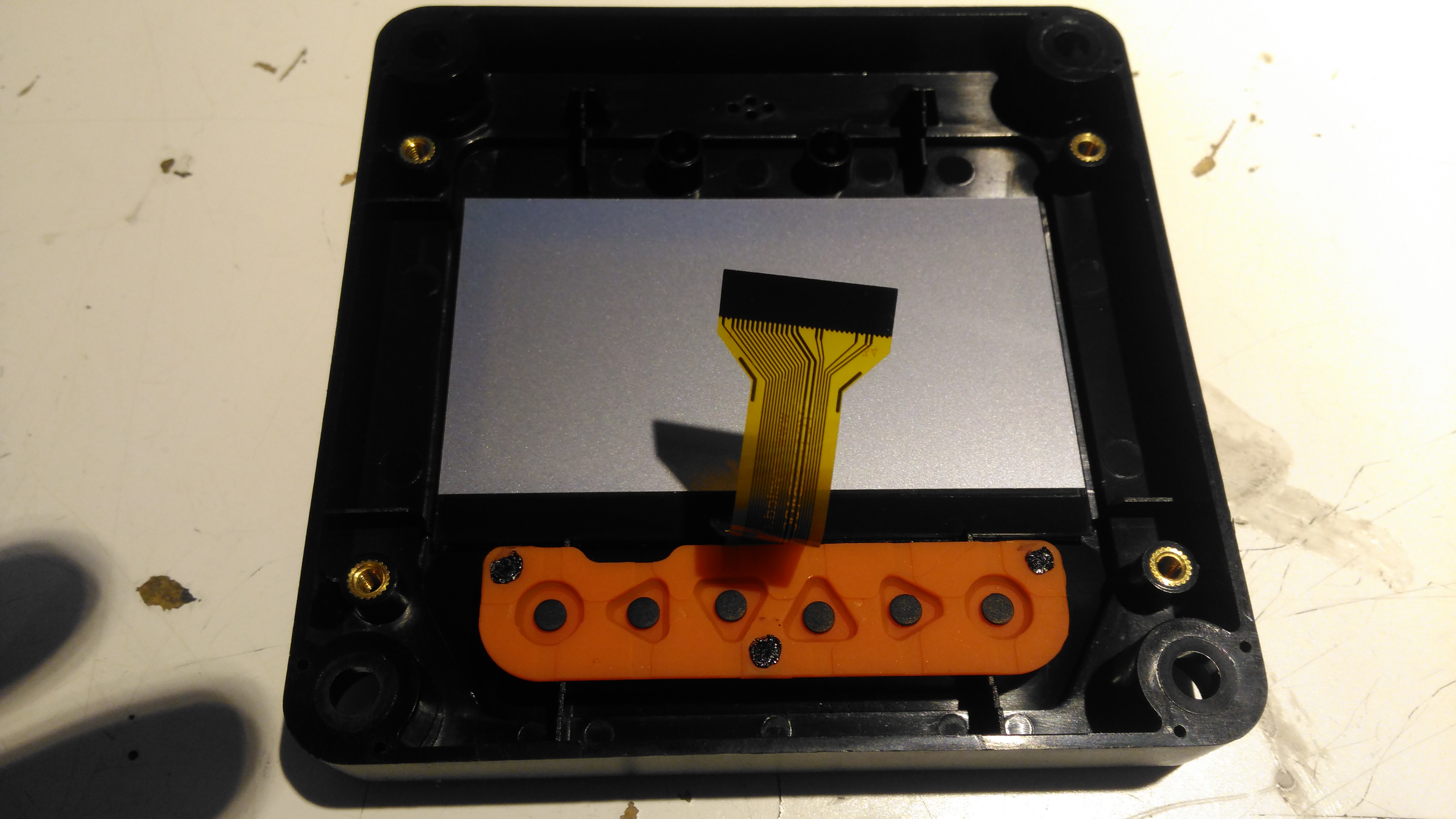
LCD Rear
The front case holds the LCD module in place with glue, and the rubber buttons are placed underneath, which is heat staked in place.
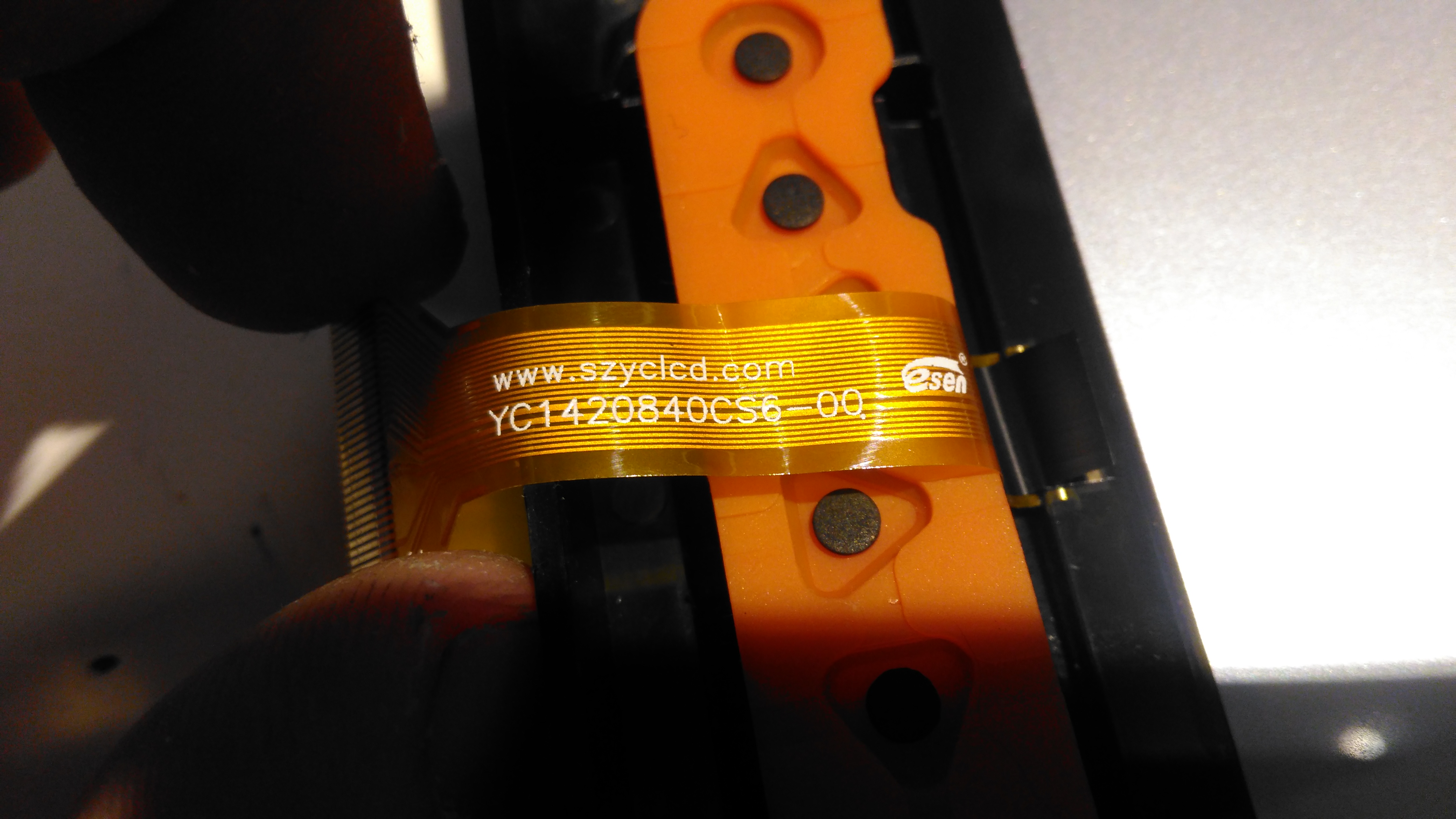
LCD Model
The LCD is a YC1420840CS6 from eCen in China. Couldn’t find much out about this specific LCD.
Here’s a very common chip used in older LCD monitors. This converts the incoming VGA signal into LVDS for the panel itself.
gmZAN3 Die
The gmZAN3 is a graphics processing IC for Liquid Crystal Display (LCD) monitors at XGA resolution. It provides all key IC functions required for the highest quality LCD monitors. On-chip functions include
a high-speed triple-ADC and PLL, a high quality zoom and shrink scaling engine, an on-screen display (OSD) controller and digital color controls.
For some time now I’ve been running a large disk array to store all the essential data for my network. The current setup has 10x 4TB disks in a RAID6 array under Linux MD.
Up until now the disks have been running in external Orico 9558U3 USB3 drive bays, through a PCIe x1 USB3 controller. However in this configuration there have been a few issues:
Congestion over the USB3 link. RAID rebuild speeds were severely limited to ~20MB/s in the event of a failure. General data transfer was equally as slow.
Drive dock general reliability. The drive bays are running a USB3 – SATA controller with a port expander, a single drive failure would cause the controller to reset all disks on it’s bus. Instead of losing a single disk in the array, 5 would disappear at the same time.
Cooling. The factory fitted fans in these bays are total crap – and very difficult to get at to change. A fan failure quickly allows the disks to heat up to temperatures that would cause failure.
Upgrade options difficult. These bays are pretty expensive for what they are, and adding more disks to the USB3 bus would likely strangle the bandwidth even further.
Disk failure difficult to locate. The USB3 interface doesn’t pass on the disk serial number to the host OS, so working out which disk has actually failed is difficult.
To remedy these issues, a proper SATA controller solution was required. Proper hardware RAID controllers are incredibly expensive, so they’re out of the question, and since I’m already using Linux MD RAID, I didn’t need a hardware controller anyway.
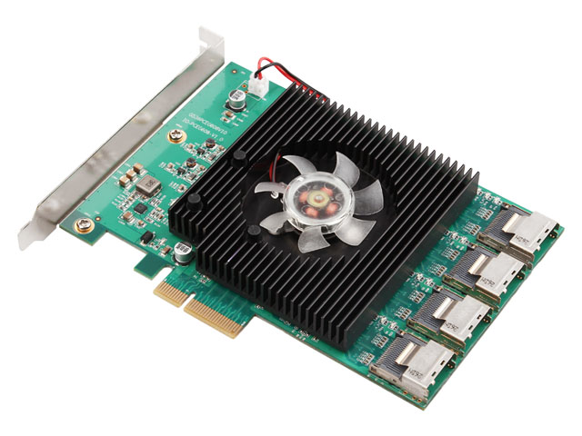
16-Port HBA
A quick search for suitable HBA cards showed me the IOCrest 16-port SATAIII controller, which is pretty low cost at £140. This card breaks out the SATA ports into standard SFF-8086 connectors, with 4 ports on each. Importantly the cables to convert from these server-grade connectors to standard SATA are supplied, as they’re pretty expensive on their own (£25 each).
This card gives me the option to expand the array to 16 disks eventually, although the active array will probably be kept at 14 disks with 2 hot spares, this will give a total capacity of 48TB.
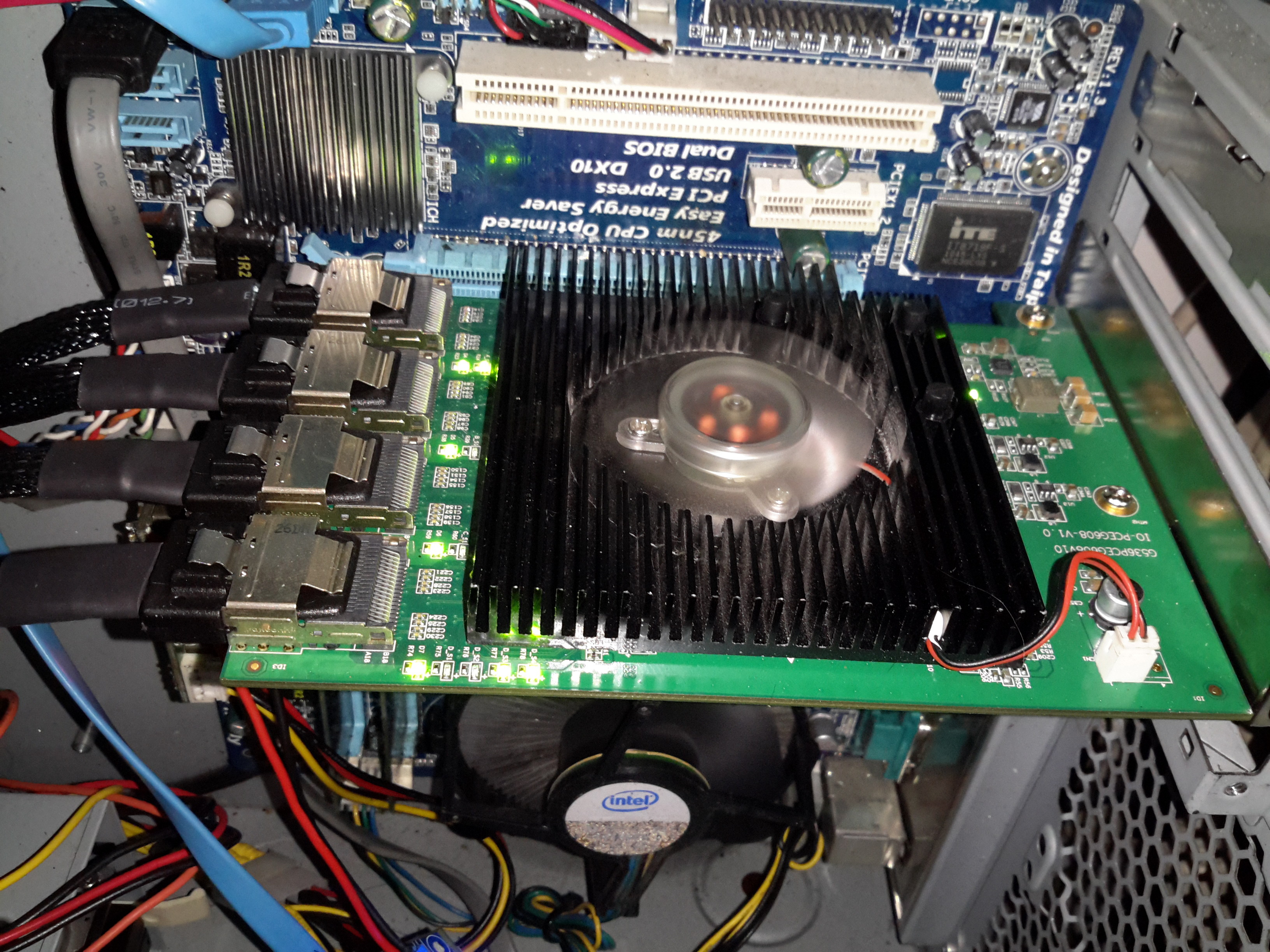
SATA HBA
Here’s the card installed in the host machine, with the array running. One thing I didn’t expect was the card to be crusted with activity LEDs. There appears to be one LED for each pair of disks, plus a couple others which I would expect are activity on the backhaul link to PCIe. (I can’t be certain, as there isn’t any proper documentation anywhere for this card. It certainly didn’t come with any ;)).
I’m not too impressed with the fan that’s on the card – it’s a crap sleeve bearing type, so I’ll be keeping a close eye on this for failure & will replace with a high quality ball-bearing fan when it finally croaks. The heatsink is definitely oversized for the job, with nothing installed above the card barely gets warm, which is definitely a good thing for life expectancy.
Update 10/02/17 – The stock fan is now dead as a doornail after only 4 months of continuous operation. Replaced with a high quality ball-bearing 80mm Delta fan to keep things running cool. As there is no speed sense line on the stock fan, the only way to tell it was failing was by the horrendous screeching noise of the failing bearings.
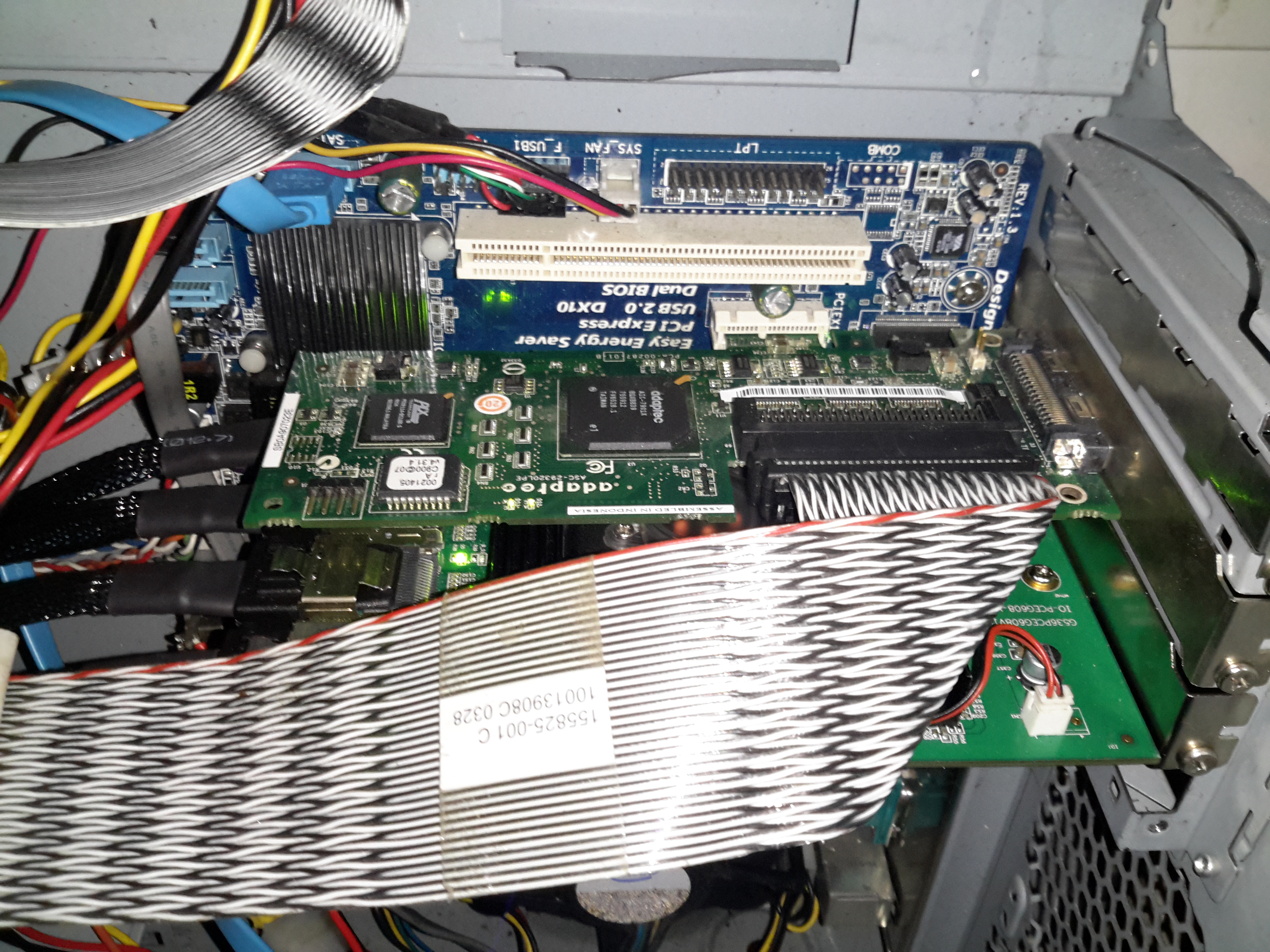
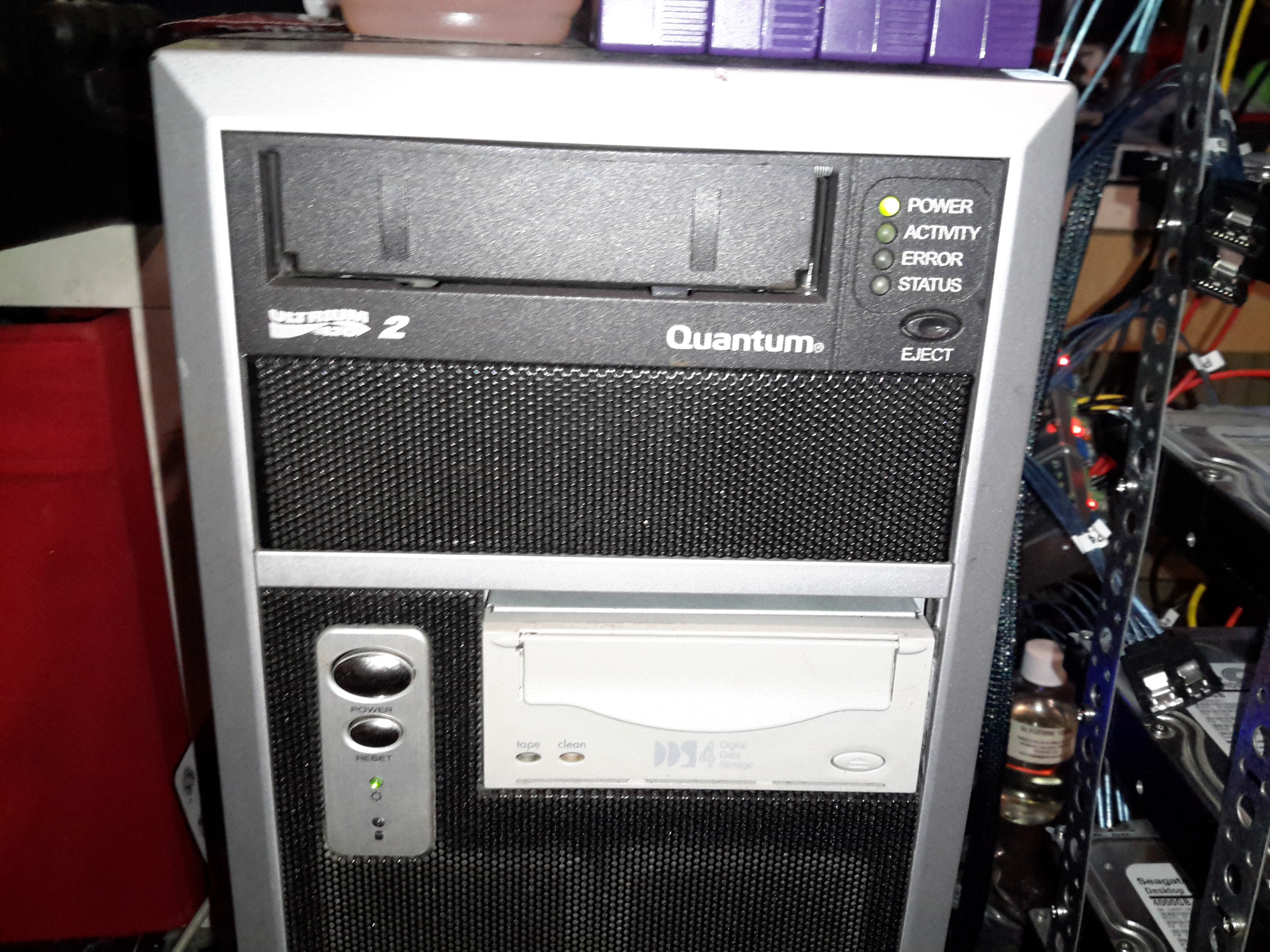
SCSI Controller
Above is the final HBA installed in the PCIe x1 slot above – a parallel SCSI U320 card that handles the tape backup drives. This card is very close to the cooling fan of the SATA card, and does make it run warmer, but not excessively warm. Unfortunately the card is too long for the other PCIe socket – it fouls on the DIMM slots.
Backup Drives
The tape drives are LTO2 300/600GB for large file backup & DDS4 20/40GB DAT for smaller stuff. These were had cheap on eBay, with a load of tapes. Newer LTO drives aren’t an option due to cost.
The main disk array is currently built as 9 disks in service with a single hot spare, in case of disk failure, this gives a total size after parity of 28TB:
/dev/md0:
        Version : 1.2
  Creation Time : Wed Mar 11 16:01:01 2015
     Raid Level : raid6
     Array Size : 27348211520 (26081.29 GiB 28004.57 GB)
  Used Dev Size : 3906887360 (3725.90 GiB 4000.65 GB)
   Raid Devices : 9
  Total Devices : 10
    Persistence : Superblock is persistent

  Intent Bitmap : Internal

    Update Time : Mon Nov 14 14:28:59 2016
          State : active
 Active Devices : 9
Working Devices : 10
 Failed Devices : 0
  Spare Devices : 1

         Layout : left-symmetric
     Chunk Size : 64K

           Name : Main-PC:0
           UUID : 266632b8:2a8a3dd3:33ce0366:0b35fad9
         Events : 773938

    Number   Major   Minor   RaidDevice State
       0       8       48        0      active sync   /dev/sdd
       1       8       32        1      active sync   /dev/sdc
       9       8       96        2      active sync   /dev/sdg
      10       8      112        3      active sync   /dev/sdh
      11       8       16        4      active sync   /dev/sdb
       5       8      176        5      active sync   /dev/sdl
       6       8      144        6      active sync   /dev/sdj
       7       8      160        7      active sync   /dev/sdk
       8       8      128        8      active sync   /dev/sdi

      12       8        0        -      spare   /dev/sda
The disks used are Seagate ST4000DM000 Desktop HDDs, which at this point have ~15K hours on them, and show no signs of impending failure.
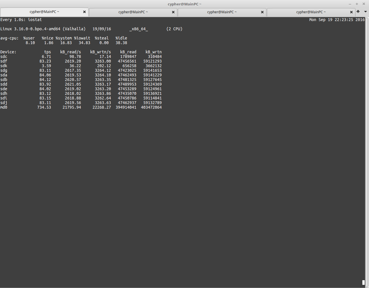
USB3 Speeds
Here’s a screenshot with the disk array fully loaded running over USB3. The aggregate speed on the md0 device is only 21795KB/s. Extremely slow indeed.
This card is structured similarly to the external USB3 bays – a PCI Express bridge glues 4 Marvell 9215 4-port SATA controllers into a single x8 card. Bus contention may become an issue with all 16 ports used, but as far with 9 active devices, the performance increase is impressive. Adding another disk to the active array would certainly give everything a workout, as rebuilding with an extra disk will hammer both read from the existing disks & will write to the new.
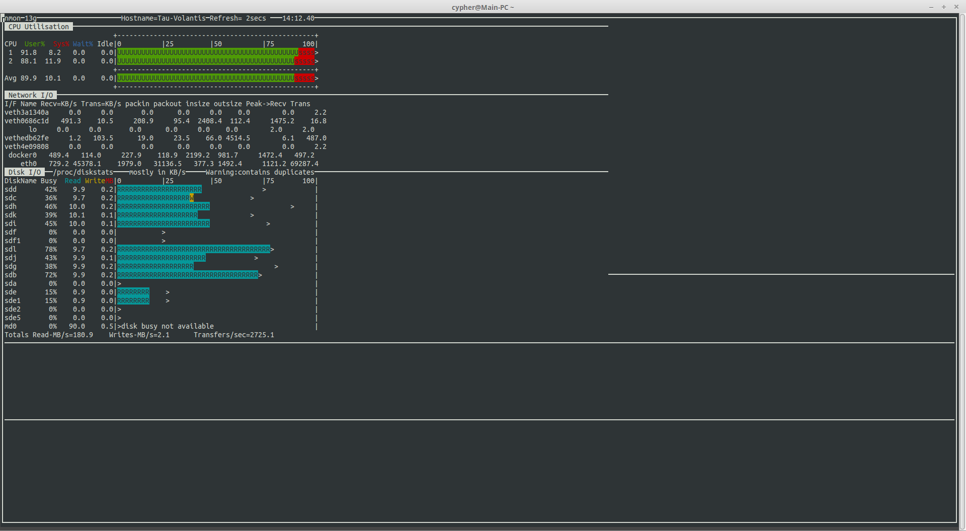
HBA Speeds
With all disks on the new controller, I’m sustaining read speeds of 180MB/s. (Pulling data off over the network). Write speeds are always going to be pretty pathetic with RAID6, as parity calculations have to be done. With Linux MD, this is done by the host CPU, which is currently a Core2Duo E7500 at 2.96GHz, with this setup, I get 40-60MB/s writes to the array with large files.
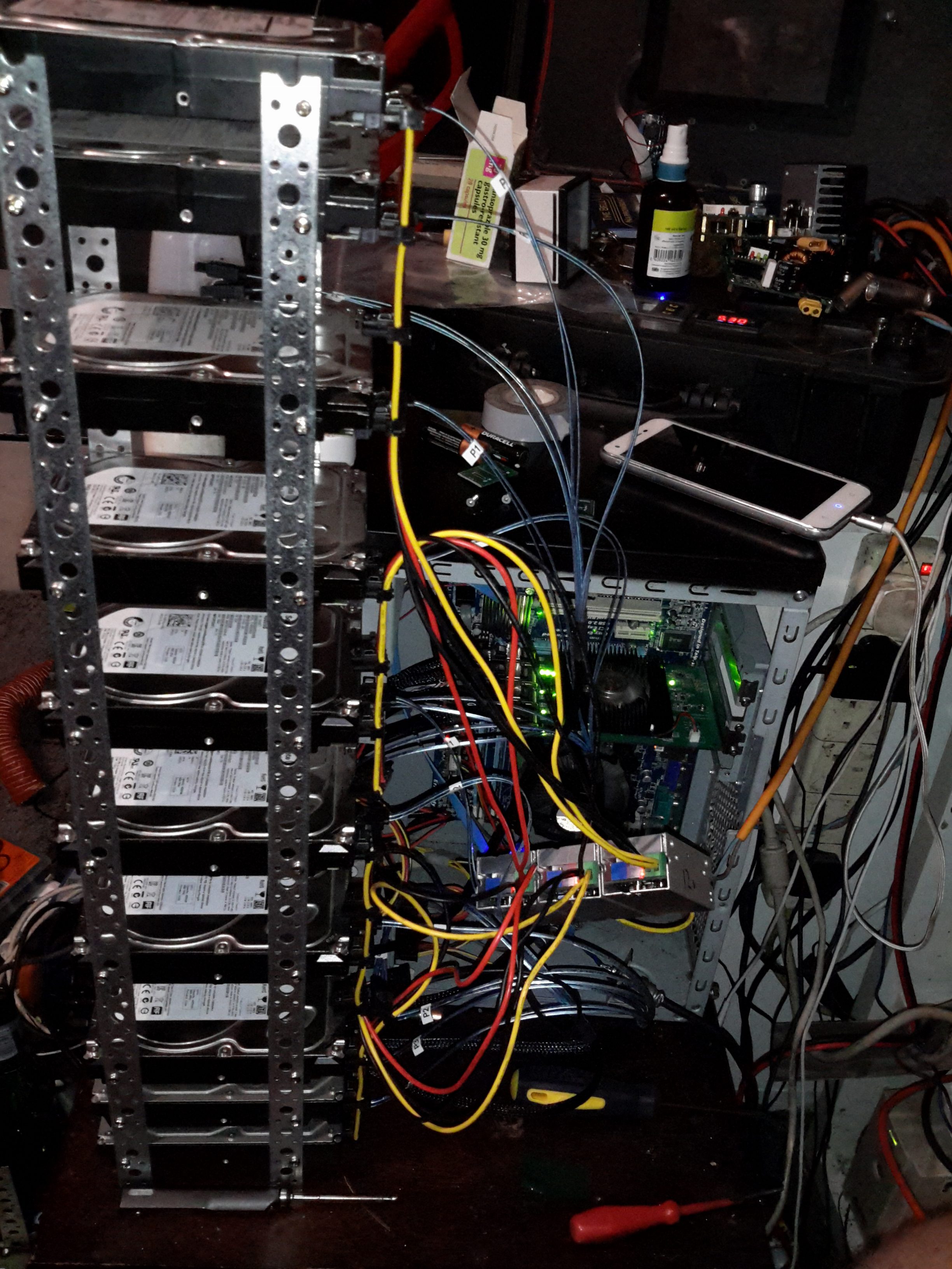
Disk Array
Since I don’t have a suitable case with built in drive bays, (again, they’re expensive), I’ve had to improvise with some steel strip to hold the disks in a stack. 3 DC-DC converters provides the regulated 12v & 5v for the disks from the main unregulated 12v system supply. Both the host system & the disks run from my central battery-backed 12v system, which acts like a large UPS for this.
The SATA power splitters were custom made, the connectors are Molex 67926-0001 IDC SATA power connectors, with 18AWG cable to provide the power to 4 disks in a string.
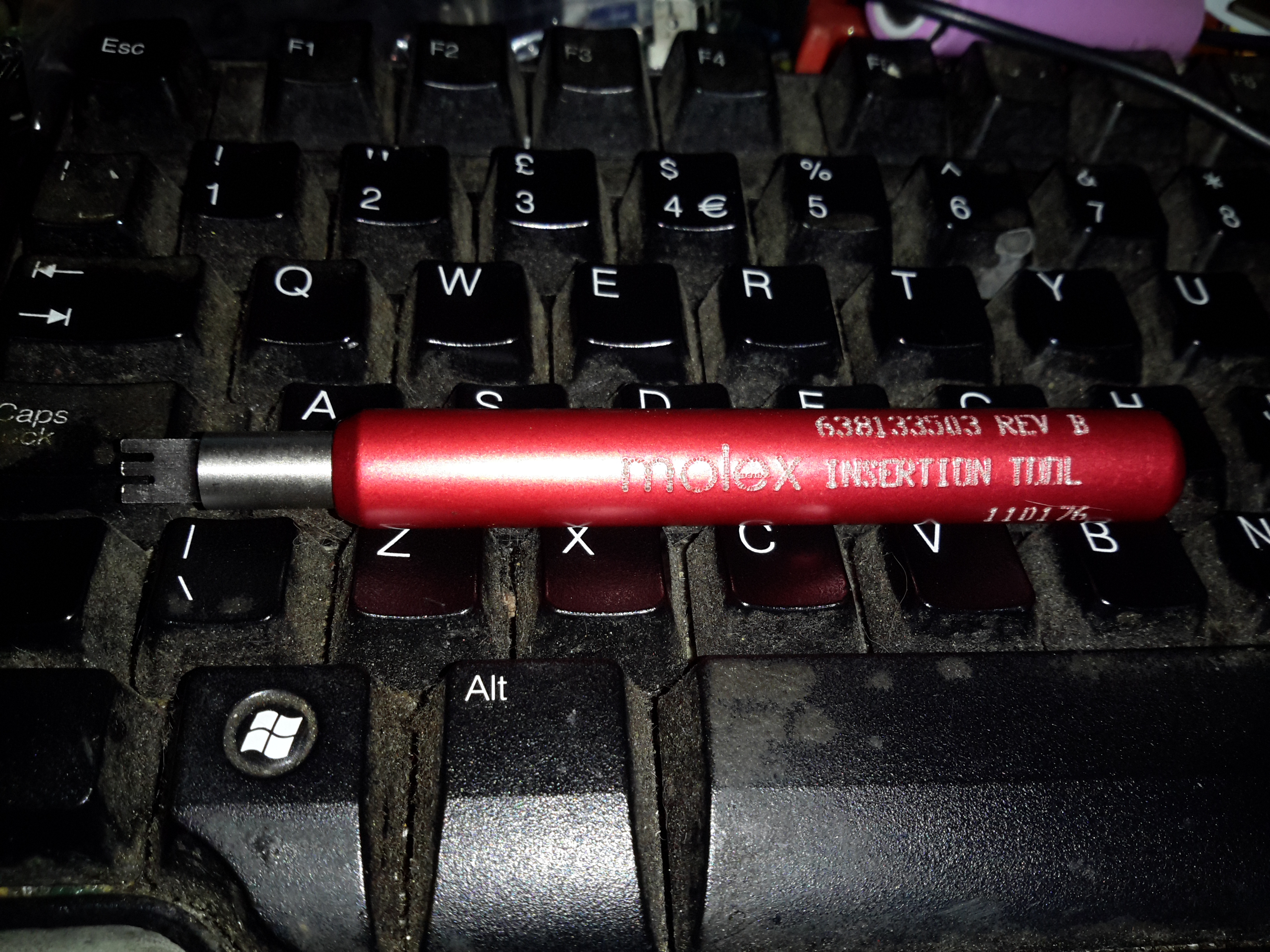
IDT Insertion Tool
These require the use of a special tool if you value your sanity, which is a bit on the expensive side at £25+VAT, but doing it without is very difficult. You get a very well made tool for the price though, the handle is anodised aluminium & the tool head itself is a 300 series stainless steel.
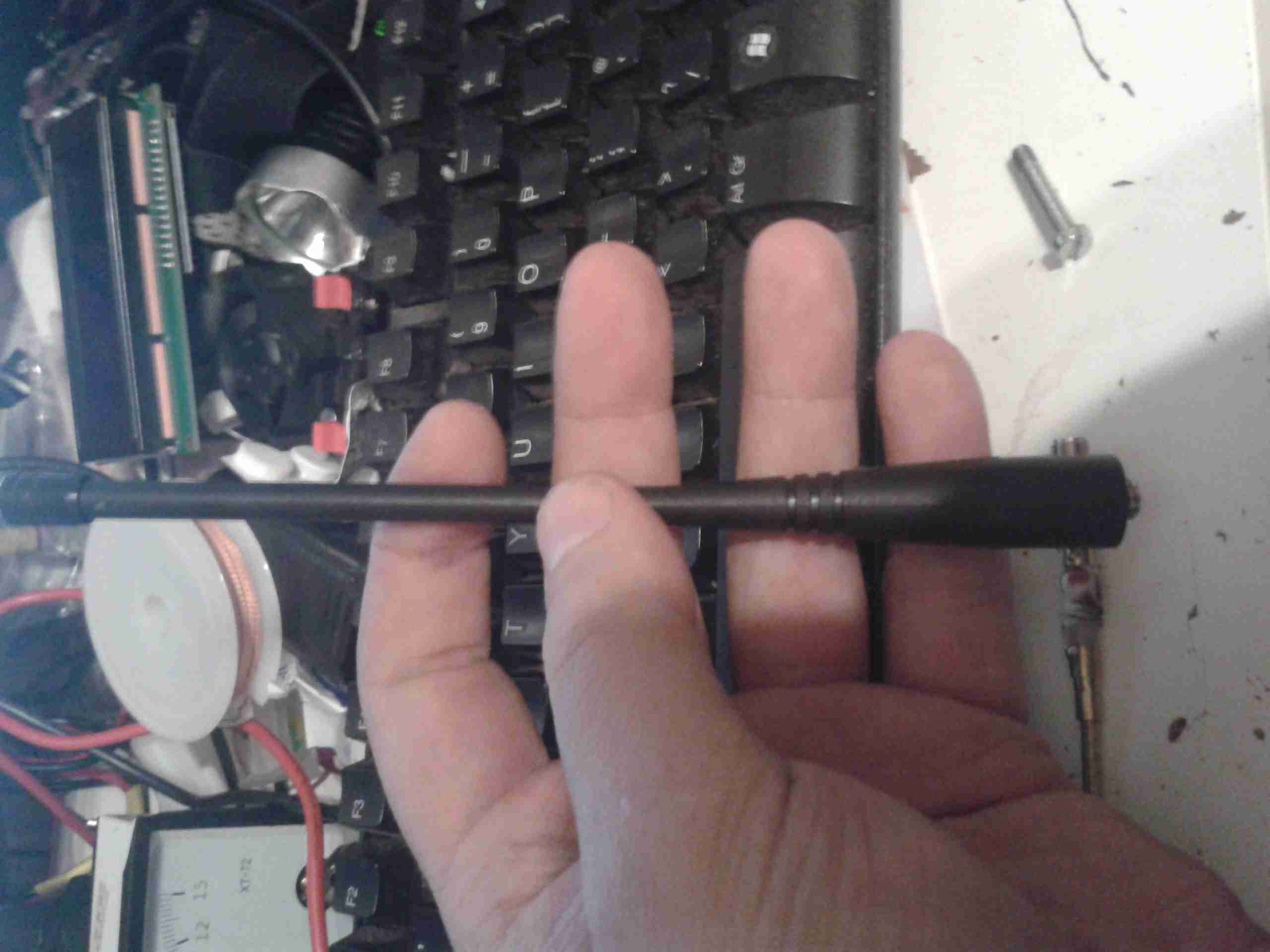
For a classroom introduction to lasers, it would be nice to have a safe setup that makes as much as possible visible to the students. Or, you may just want to have a working He-Ne laser on display in your living room! Ideally, this is an external mirror laser where all parts of the resonator as well as the power supply can be readily seen. However, realistically, finding one of these is not always that easy or inexpensive, and maintenance and adjustment of such a laser can be a pain (though that in itself IS instructive).
The next best thing is a small He-Ne laser laid bare where its sealed (internal mirror) He-Ne tube, ballast resistors, wiring, and power supply (with exposed circuit board), are mounted inside a clear Plexiglas case with all parts labelled. This would allow the discharge in the He-Ne tube to be clearly visible. The clear insulating case prevents the curious from coming in contact with the high voltage (and line voltage, if the power supply connects directly to the AC line), which could otherwise result in damage to both the person and fragile glass He-Ne tube when a reflex action results in smashing the entire laser to smithereens!
A He-Ne laser is far superior to a cheap laser pointer for several reasons:
The discharge and mirrors are clearly visible permitting the lasing process to be described in detail. Compared to this, a diode laser pointer is about as exciting as a flashlight even if you are able to extract the guts.
The beam quality in terms of coherence length, monochromaticy, shape, and stability, will likely be much higher for the He-Ne laser should you also want to use it for actual optics experiments like interferometry. (However, the first one of these – coherence length – can actually be quite good for even the some of the cheap diode lasers in laser pointers.)
For a given power level, a 632.8nm He-Ne laser will appear about 5 times brighter than a 670 nm laser pointer. 635 nm laser pointers are available but still more expensive. However, inexpensive laser pointers with wavelengths between 650 and 660 nm are becoming increasingly common and have greater relative brightness.
Important: If this see-through laser is intended for use in a classroom, check with your regulatory authority to confirm that a setup which is not explicitly CDRH approved (but with proper laser class safety stickers) will be acceptable for insurance purposes.
For safety with respect to eyeballs and vision, a low power laser – 1 mW or less – is desirable – and quite adequate for demonstration purposes.
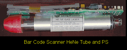
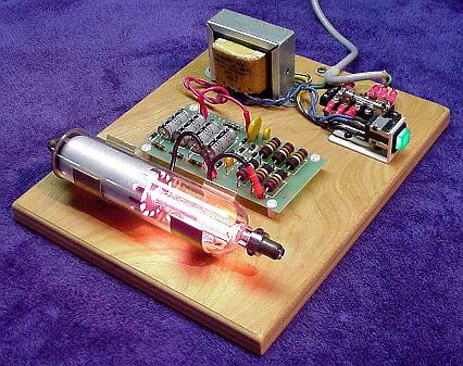
The He-Ne laser assembly from a barcode scanner is ideal for this purpose. It is compact, low power, usually runs on low voltage DC (12 V typical), and is easily disassembled to remount in a demonstration case. The only problem is that many of these have fully potted “brick” type power supplies which are pretty boring to look at. However, some have the power supply board coated with a rubbery material which can be removed with a bit of effort (well, OK, a lot of effort!).
He-Ne Tube and Power Supply
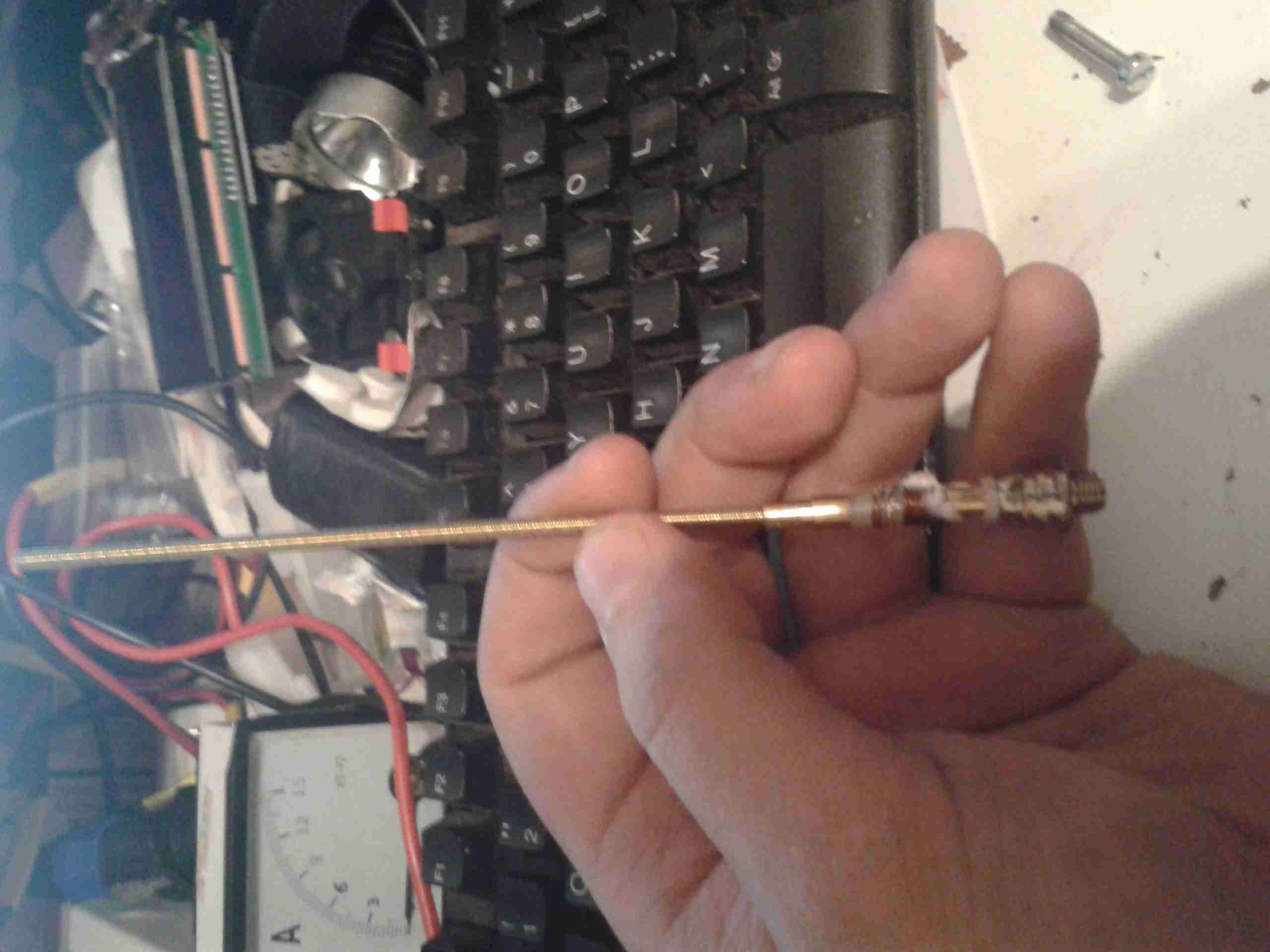
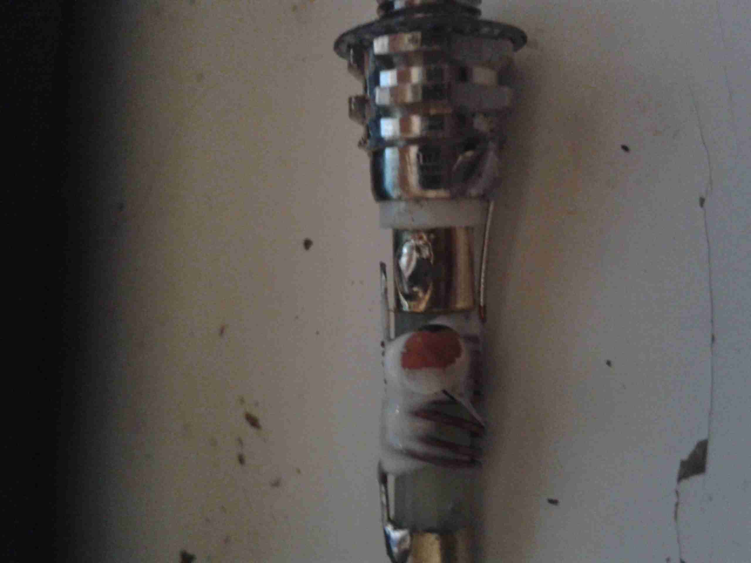
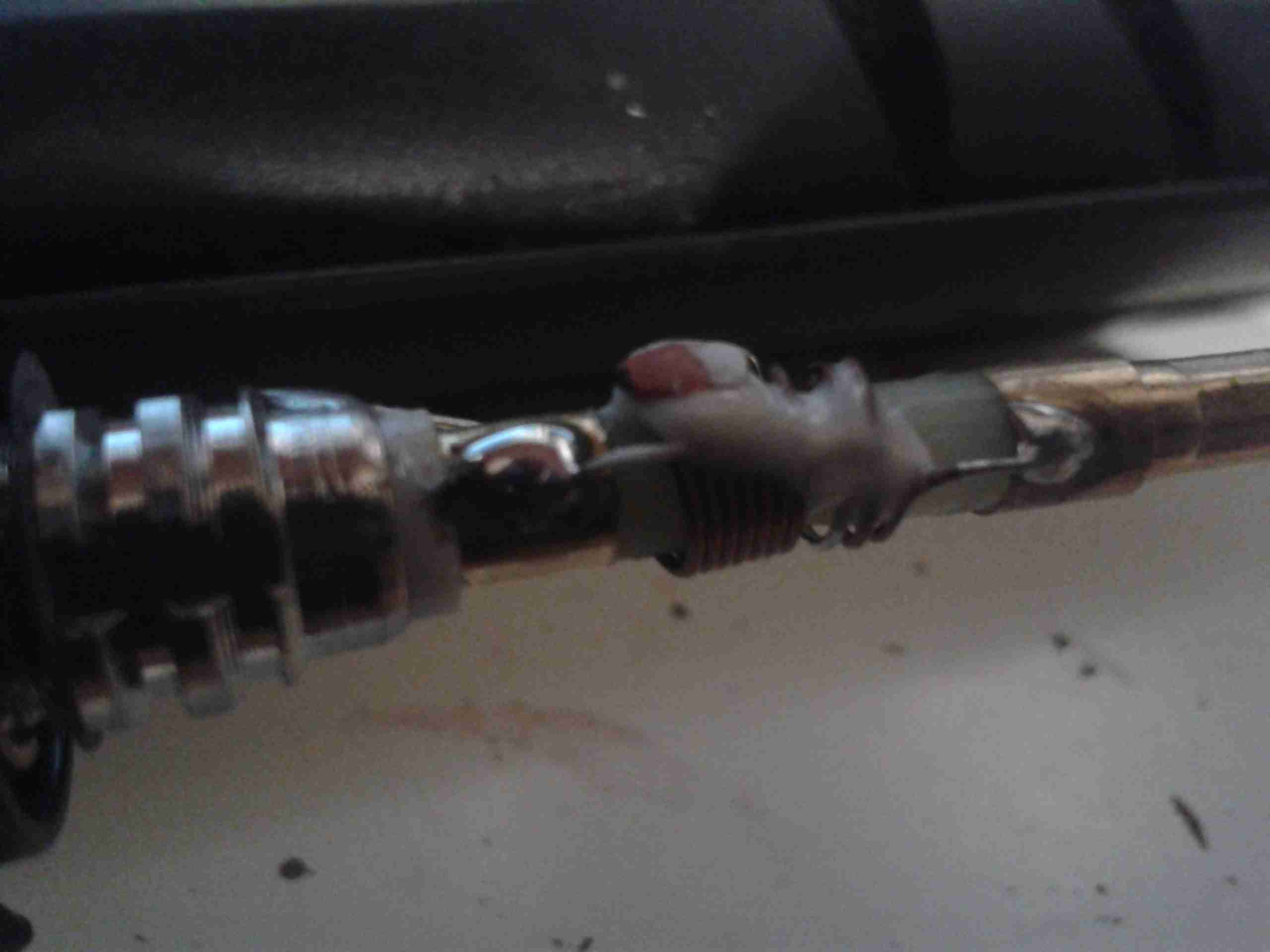
For example, this is from a hand-held barcode scanner. A similar unit was separated into its component parts:
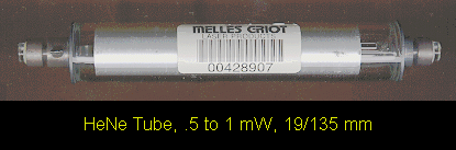
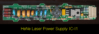
Melles Griot He-Ne TubeHe-Ne Laser Power Supply IC-I1
The power supply includes the ballast resistors. These could easily be mounted in a very compact case (as little as 3″ x 6″ x 1″, though spreading things out may improve visibility and reduce make cooling easier) and run from a 12v DC, 1 A wall adapter. Used barcode scanner lasers can often be found for $20 or less.
An alternative is to purchase a 0.5 to 1 mW He-Ne tube and power supply kit. This will be more expensive (figure $5 to $15 for the He-Ne tube, $25 to $50 for the power supply) but will guarantee a circuit board with all parts visible.
The He-Ne tube, power supply, ballast resistors (if separate from the power supply), and any additional components can be mounted with standoffs and/or cable ties to the plastic base. The tube can be separated from the power supply if desired to allow room for labels and such. However, keep the ballast resistors as near to the tube as practical (say, within a couple of inches, moving them if originally part of the power supply board). The resistors may get quite warm during operation so mount them on standoffs away from the plastic. Use wire with insulation rated for a minimum of 10 kV. Holes or slots should be incorporated in the side panels for ventilation – the entire affair will dissipate 5 to 10 Watts or more depending on the size of the He-Ne tube and power supply.
When attaching the He-Ne tube, avoid anything that might stress the mirror mounts. While these are quite sturdy and it is unlikely that any reasonable arrangement could result in permanent damage, even a relatively modest force may result in enough mirror misalignment to noticeably reduce output power. And, don’t forget that the mirror mounts are also the high voltage connections and need to be well insulated from each other and any human contact! The best option is probably to fasten the tube in place using Nylon cable ties, cable clamps, or something similar around the glass portion without touching the mirror mounts at all (except for the power connections).
Provide clearly marked red and black wires (or binding posts) for the low voltage DC or a line cord for AC (as appropriate for the power supply used), power switch, fuse, and power-on indicator. Label the major components and don’t forget the essential CDRH safety sticker (Class II for less than 1 mW or Class IIIa for less than 5 mW).
See:
Sam’s Demo He-Ne Laser
Above, as an example (minus the Plexiglas safety cover), contructed from the guts of a surplus Gammex laser (probably part of a patient positioning system for a CT or MRI scanner). The discrete line operated power supply is simple with the HV transformer, rectifier/doubler, filter, multiplier, and ballast resistors easily identified. This would make an ideal teaching aid.
Rather than having a see-through laser that just outputs a laser beam (how boring!), consider something that would allow access to the internal cavity, swapping of optics, and modulation of beam power. OK, perhaps the truly ultimate demo laser would use a two-Brewster tube allowing for interchangeable optics at both ends, be tunable to all the He-Ne spectral lines, and play DVD movies. 🙂 We’ll have to settle for something slightly less ambitious (at least until pigs fly). Such a unit could consist of the following components:
One-Brewster He-Ne laser tube or head. This can be something similar to the Melles Griot 05-LHB-570 tube or the Climet 9048 head which contains this tube. These have a Brewster window at one end and an internal HR mirror with a 60 cm Radius of Curvature (RoC) at the other. Their total length is about 10.5 inches (260 mm).
Adjustable mirror mount with limited range to permit easy mirror tweaking but with minimal chance of getting alignment really messed up. A basic design using a pair of plates with X and Y adjustment screws and a common pivot with lock washers for the compliance springs would be adequate.
Interchangeable mirrors of RoC = 60 cm and reflectance of 98% to 99.5% (OC) and 99.999% (HR in place of OC to maximize internal photon flux). These may be salvaged from a dead 3 to 5 mW He-Ne laser tube. Those from a tube like the Spectra-Physics 084-1 would be suitable. It would be best to install the mirrors in protective cells for ease of handling.
Baseplate to mount the laser and optics with the internal HR of the one-Brewster tube/head about 60 cm from the external mirror to create a confocal cavity – about one half of which is external and accessible. An option would be to put the external mirror mount on a movable slide to allow its position to be changed easily.
Power supply with adjustable current and modulation capability. This would provide the ability to measure output power versus current and to use the laser as an optical transmitter with a solar cell based receiver.
Plexiglas box to house and protect the laser and power supply (as well as inquisitive fingers from high voltage) with part of one side open to allow access to the internal photons.
Everything needed for such a setup is readily available or easily constructed at low cost but you’ll have to read more to find out where or how as each of the components are dealt with in detail elsewhere in Sam’s Laser FAQ (but I won’t tell you exactly where – these are all the hints you get for this one!).
A system like this could conceivably be turned into an interactive exhibit for your local science museum – assuming they care about anything beyond insects and the Internet these days. 🙂 There are some more details in the next section.
Guidelines for a Demonstraton One-Brewster He-Ne Laser
The following suggestions would be for developing a semi-interactive setup whereby visitors can safely (both for the visitor and the laser) adjust mirror alignment and possibly some other parameters of laser operation. The type of one-Brewster (1-B) He-Ne laser tube like the Melles Griot 05-LHB-570. Note that the 05-LHB-570 is a wide bore tube that runs massively multi (transverse) mode with most mirrors configurations unless an intracavity aperture is added. This is actually an advantage for several reasons:
The multi-transverse mode structure is interesting in itself and provides additional options for showing how it can be controlled.
Mirror alignment is easier and the tube will lase over a much wider range of mirror orientation.
Output power is higher for its size and power requirements.
Here are some guidelines for designing an interactive exhibit:
Mount the 1-B tube in a clear plastic (Plexiglas) enclosure with some ventilation holes to allow for cooling but make sure any parts with high voltage (anode, ballast resistors if not insulated) are safely protected from the curious. Provide a small hole lined up with the Brewster window for the intracavity beam. However, even if the B-window is at the cathode-end of the tube, don’t allow it to be accessible as the first fingerprint will prevent lasing entirely.
Put the power supply in a safe place inside another clear plastic box if desired. I’d recommend controlling it with a time switch that will turn it on for perhaps 10 minutes with a push of a button. This is a tradeoff between wear from running the laser all the time and wear from repeated starts. Don’t forget the fuse!!!
Orient the tube so the B-windows is either on the side or facing down. This will minimize dust collection and permit the rig to operate for many hours or days without the need for even dusting.
Use an output mirror with an RoC from 50 cm to planar and reflectivity of 98 to 99.5 percent at 632.8 nm. The specific parameters and distance will affect the beam size, mode structure, and output power. A shorter RoC will limit the distance over which lasing will take place but will be somewhat easier to align.
Use a decent quality mirror mount like a Newport MM-1 for the output mirror. Once it’s secured, arrange for the adjustment screws to be accessible to visitors but limit the range of rotation to less than one turn and mark the location of each screw where lasing is peaked. That way, no amount of fiddling will lose lasing entirely.
The distance between the mirror and tube can be fixed or adjustable:
For a fixed location, a distance of a few inches between the laser enclosure and mirror mount is recommended. This is enough space to install an aperture or Brewster plate. Or a hand to show that the beam is only present with the resonator is complete, not just a red light inside! But, it’s short enough that alignment is still easy.
For added excitement, put the mirror mount on a precision rail to permit the distance to be varied from 0 to at least 45 cm from the B-window. Then, it will be possible to see how the mode structure changes with distance. This will depend on the RoC of the mirror as well.
Another option is to provide various things like an iris diaphragm, thin wires and/or a cross-hair, adjustable knife edge, Brewster plate that can be oriented, etc. However, some care will be needed in making these useful without a lot of hand holding.
Weatherproofing a He-Ne Laser
If you want to use a He-Ne laser outside or where it is damp or very humid, it will likely be necessary to mount the tube and power supply inside a sealed box. Otherwise, stability problems may arise from electrical leakage or the tube may not start at all. There will then be several additional issues to consider:
Heat dissipation – For a small He-Ne tube (say 1 mW), figure this is like a 10 to 15 W bulb inside a plastic box. If you make the box large enough (e.g., 3″ x 5″ x 10″), there should be enough exterior surface area to adequately remove the waste heat.
Getting the beam out – A glass window (e.g., quality microscope slide) mounted at a slight angle (to avoid multiple reflections back to the He-Ne tube output mirror) is best. However, a Plexiglas window may be acceptable (i.e., just pointing the laser at a slight angle through the plastic case). A Brewster angle window should be used only if the He-Ne tube is a linearly polarized type (not likely for something from a barcode scanner) and then the orientation and angle must be set up for maximum light transmission.
Condensation on the optics and elsewhere – This may be a problem on exposed surfaces if they are colder than the ambient conditions. Let the entire laser assembly warm up before attempting to power it up!
Prior to the introduction of the CD player, the red He-Ne laser was by far the most common source of inexpensive coherent light on the planet. The following are some typical physical specifications for a variety of red (632.8 nm) He-Ne tubes (all are single transverse mode – TEM00):
   Output       Tube Voltage       Tube         Tube Size
   Power        Operate/Start     Current      Diam/Length
 ------------  ---------------  ------------  -------------
  0.3-0.5 mW    0.8-1.0/6  kV    3.0-4.0 mA     19/135 mm
  0.5-1 mW       .9-1.0/7  kV    3.2-4.5 mA     25/150 mm
   1-2 mW       1.0-1.4/8  kV    4.0-5.0 mA     30/200 mm
   2-3 mW       1.1-1.7/8  kV    4.0-6.5 mA     30/260 mm
   3-5 mW       1.7-2.4/10 kV    4.5-6.5 mA     37/350 mm
   5-10 mW      2.4-3.1/10 kV    6.5-7.0 mA     37/440 mm
  10-15 mW      3.0-3.5/10 kV    6.5-7.0 mA     37/460 mm
  15-25 mW      3.3-4.0/10 kV    6.5-7.0 mA     37/600 mm
  25-35 mW      4.0-5.2/12 kV    7.0-8.0 mA     42/900 mm
Where:
Power Output is the minimum beam power after a specified warm up period over the spec’d life of the tube.
Tube Operating Voltage is the voltage across the bare tube at the nominal operating current.
Tube Start Voltage is the minimum voltage across the bare tube required to guarantee starting.
Tube Size is generally the maximum diameter of the tube envelope and the total length from the outer surfaces of the mirrors.
Tubes like this are generally available in both random and linearly polarized versions which are otherwise similar with respect to the above characteristics (for red tubes at least, more below).
At least one other basic specification may be critical to your application: Which end of the tube the beam exits! There is no real preference from a manufacturing point of view for red He-Ne lasers. (For low gain “other-colour” He-Ne laser tubes, it turns out that anode output results is slightly higher gain and thus slightly higher output for the typical hemispherical cavity because it better utilizes the mode volume.) However, this little detail may matter a great deal if you are attempting to retrofit an existing barcode scanner or other piece of equipment where the tube clips into a holder or where wiring is short, tight, or must be in a fixed location. For example, virtually all cylindrical laser heads require that the beam exits from the cathode-end of the tube. It is possible that you will be able to find two versions of many models of He-Ne tubes if you go directly to the manufacturer and dig deep enough. However, this sort of information may not be stated where you are buying surplus or from a private individual, so you may need to ask.
The examples above (as well as all of the other specifications in this and the following sections) are catalog ratings, NOT what might appear on the CDRH safety sticker (which is typically much higher). See the section: About Laser Power Ratings for info on listed, measured, and CDRH power ratings.
Note how some of the power levels vary widely with respect to tube dimensions, voltage, and current. Generally, higher power implies a longer tube, higher operating/start voltages, and higher operating current – but there are some exceptions. In addition, you will find that physically similar tubes may actually have quite varied power output. This is particularly evident in the manufacturers’ listings. (See the chapter: A HREF=”laserhcl.htm#hcltoc”>Commercial Unstabilized HeNe Lasers.)
These specifications are generally for minimum power over the guaranteed life of the tube. New tubes and individual sample tubes after thousands of hours may be much higher – 1.5X is common and a “hot” sample may hit 2X or more. My guess is that for tubes with identical specifications in terms of physical size, voltage, and current, the differences in power output are due to sample-to-sample variations. Thus, like computer chips, they are selected after manufacture based on actual performance and the higher power tubes are priced accordingly! This isn’t surprising when considering the low efficiency at which these operate – extremely slight variations in mirror reflectivity and trace contaminants in the gas fill can have a dramatic impact on power output.
I have a batch of apparently identical 2 mW Aerotech tubes that vary in power output by a factor of over 1.5 to 1 (2.6 to 1.7 mW printed by hand on the tubes indicating measured power levels at the time of manufacture).
And, power output also changes with use (and mostly in the days of soft-sealed tubes, just with age sitting on the shelf):
(From: Steve Roberts.)
“I have a neat curve from an old Aerotech catalogue of He-Ne laser power versus life. The tubes are overfilled at first, so power is low. They then peak at a power much higher than rated power, followed by a long period of constant power, and then they SLOWLY die. It’s not uncommon for a new He-Ne tube to be in excess of 15% greater than rated power.”
And the answer to your burning question is: No, you cannot get a 3 mW tube to output 30 mW – even instantaneously – by driving it 10 times as hard!
I have measured the operating voltage and determined the optimum current (by maximizing beam intensity) for the following specific samples – all red (632.8 nm) tubes from various manufacturers. (The starting voltages were estimated.):
   Output     Tube Voltage       Tube         Supply Voltage     Tube Size
   Power      Operate/Start     Current        (75K ballast)    Diam/Length
 ----------  ---------------  ------------   ----------------  -------------
    .8 mW        .9/5  kV        3.2 mA           1.1 kV         19/135 mm
   1.0 mW       1.1/7  kV        3.5 mA           1.4 kV         25/150 mm
   1.0 mW       1.1/7  kV        3.2 mA           1.4 kV         25/240 mm
   2.0 mW       1.2/8  kV        4.0 mA           1.5 kV         30/185 mm
   3.0 mW       1.6/8  kV        4.5 mA           1.9 kV         30/235 mm
   5.0 mW       1.7/10 kV        6.0 mA           2.2 kV         37/350 mm
  12.0 mW       2.5/10 kV        6.0 mA           2.9 kV         37/475 mm
Melles Griot, Uniphase, Siemens, PMS, Aerotech, and other HeNe tubes all show similar values.
The wide variation in physical dimensions also means that when looking at descriptions of He-Ne lasers from surplus outfits or the like, the dimensions can only be used to determine an upper (and possibly lower) bound for the possible output power but not to determine the exact output power (even assuming the tube is in like-new condition). Advertisements often include the rating on the CDRH safety sticker (or say ‘max’ in fine print). This is an upper bound for the laser class (e.g., Class IIIa), not what the particular laser produces or is even capable of producing. It may be much lower. For example, that Class IIIa laser showing 5 mW on the sticker, may actually only be good for 1 mW under any conditions! The power output of a He-Ne laser tube is essentially constant and cannot be changed significantly by using a different power supply or by any other means. See the section: Buyer Beware for Laser Purchases.
In addition to power output, power requirements, and physical dimensions, key performance specifications for He-Ne lasers also include:
Beam Diameter at the laser’s output aperture and beam profile (Gaussian TEM00 for most small He-Ne laser tubes).
Beam Divergence (probably far field ignoring beam waist). Note that this may not always be the same as the expected value from the diffraction limit based on beam/bore diameter as it also depends on the combination of the HR and OC mirror (inside) curvature and the shape of the exterior surface of the OC.
Mode Spacing (frequency) between the multiple longitudinal modes that are active simultaneously in all but single mode frequency stabilized lasers.
With manufacturers like Aerotech, Melles Griot, and Siemens, a certain amount of information can be determined from the model number. For example, here is how to decipher most of those from Melles Griot (e.g., 05-LHP-121-278):
All Melles Griot He-Ne laser tubes and power supplies start with 05. Matched systems may start with 25 (e.g., laser head and lab-style power supply).
The first letter will be an L for all He-Ne laser tubes and heads except for perpendicular window terminated tubes (in which case it will be W – this is inconsistent with the rest of their numbering but who am I to complain!), and some of their self contained lasers where it will be S.
The second letter will be one of: H = red (632.8 nm), G = green (543.5 nm), Y = yellow (594.1 nm), O = orange (611.9 nm), or I = infra-red (1,523 or 3,391 nm). A couple of self contained red lasers use R for red but for most, I guess they got stuck using H (presumably denoting He-Ne) before ‘other colour’ He-Ne lasers were part of their product line. And, their stabilized He-Ne lasers use a T here. Confused yet? 🙂
The third letter will be one of: R = Randomly polarized, L = linearly polarized, or B = Brewster window at one or both ends.
The following three digit number determines the physical characteristics of the laser tube to some extent. Unfortunately, there may be no direct mathematical relationship of this number to anything useful. As will be seen below, for some models, it (or some of its digits) sort of correlates with output power or length but for others, they might as well be totally random! However, it does appear as though an identical set of numbers among different colour tubes (see below) will denote similar physical size tubes at least.
If there are additional numbers, they relate to a special variation on the basic design done for a particular customer. For example, this might be a different curvature on the outer surface of the output mirror to provide a non-standard divergence to eliminate the need for an additional lens in a barcode scanner. Or, an external window for protection from the elements or to deliberately reduce output power. Go figure. 🙂 It may also just denote a specific configuration like -249 (meaning 115 VAC operation, kind of arbitrary, huh?) or -55 (meaning 5.5 mA). In these cases, the user may be able to modify the settings (flip a switch or twiddle a pot) but the warranty may then be void.
The vast majority of Melles Griot lasers you are likely to come across will follow this numbering scheme though there are some exceptions, especially for custom assemblies. (Some surplus places drop the leading ’05-‘ when reselling Melles Griot laser tubes or heads so an 05-LHP-120 would become simply an LHP-120.)
For other manufacturers like Spectra-Physics, the model numbers are totally arbitrary!
He-Ne Tubes of a Different Colour
Although a red beam is what everyone thinks of when a He-Ne laser is discussed, He-Ne tubes producing green, yellow, and orange beams, as well as several infra-red (IR) wavelengths, are also manufactured. However, they are not found as often on the surplus market because they are not nearly as common as the red variety. In terms of the number of He-Ne lasers manufactured, red is far and away the most popular, with all the others combined accounting for only 1 to 2 percent of the total production. In order of decreasing popularity, it’s probably: red, green, yellow, infra-red (all IR wavelengths), orange. Non-red tubes are also more expensive when new since for a given power level, they must be larger (and thus have higher voltage and current ratings) due to their lower efficiency (the spectral lines being amplified are much weaker than the one at 632.8 nm). Operating current for non-red He-Ne tubes is also more critical than for the common red variety so setting these up with an adjustable power supply or adjusting the ballast resistance for maximum output is recommended.
Maximum available power output is also lower – rarely over 2 mW (and even those tubes are quite large (see the tables below). However, since the eye is more sensitive to the green wavelength (543.5 nm) compared to the red (632.8 nm) by more than a factor of 4, a lower power tube may be more than adequate for many applications. Yellow (594.1 nm) and orange (611.9 nm) He-Ne lasers appear more visible by factors of about 3 and 2 respectively compared to red beams of similar power.
Infrared-emitting He-Ne lasers exist as well. In addition to scientific uses, these were used for testing in the Telecom industry before sufficiently high quality diode lasers became available.Yes, you can have a He-Ne tube and it will light up inside (typical neon glow), but if there is no output beam (at least you cannot see one), you could have been sold an infrared He-Ne tube. However, by far the most likely explanation for no visible output beam is that the mirrors are misaligned or the tube is defective in some other way. Unfortunately, silicon photodiodes or the silicon sensors in CCD or CMOS cameras do not respond to any of the He-Ne IR wavelengths, so the only means of determining if there is an IR beam are to use a GaAs photodiode, IR detector card, or thermal laser power meter. IR He-Ne tubes are unusual enough that it is very unlikely you will ever run into one. However, they may turn up on the surplus market especially if the seller doesn’t test the tubes and thus realize that these behave differently – they are physically similar to red (or other colour) He-Ne tubes except for the reflectivity of the mirrors as a function of wavelength. (There may be some other differences needed to optimize each color like the He:Ne ratio, isotope purity, and gas fill pressure, but the design of the mirrors will be the most significant factor and the one that will be most obvious with a bare eyeball, though the color of the discharge may be more pink for green He-Ne tubes and more orange and brighter for IR He-Ne tubes compared to red ones, more below.) Even if the model number does not identify the tube as green, yellow, orange, red, or infra-red, this difference should be detectable by comparing the appearance of its mirrors (when viewed down the bore of an UNPOWERED tube) with those of a normal (known to be red) He-Ne tube. (Of course, your tube could also fail to lase due to misaligned or damaged mirrors or some other reason.
As noted above, the desired wavelength is selected and the unwanted wavelengths are suppressed mostly by controlling the reflectivity functions of the mirrors. For example, the gains of the green and yellow lines (yellow may be stronger) are both much much lower than red and separated from each other by about 50 nm (543.5 nm versus 594.1 nm). To kill the yellow line in a green laser, the mirrors are designed to reflect green but pass yellow. I have tested the mirrors salvaged from a Melles Griot 05-LGP-170 green He-Ne tube (not mine, from “Dr. Destroyer of Lasers”). The HR (High Reflector) mirror has very nearly 100% reflectivity for green but less than 25% for yellow. The OC (Output Coupler) also has a low enough reflectivity for yellow (about 98%) such that it alone would prevent yellow from lasing. The reflectivities for orange, red, and IR, are even lower so they are also suppressed despite their much higher gain, especially for the normal red (632.8 nm) and even stronger mid-IR (3,391 nm) line.
However, to manufacture a tube with optimum and stable output power, it isn’t sufficient to just kill lasing for unwanted lines. The resonator must be designed to minimize their contribution to stimulated emission – thus the very low reflectivity of the HR for anything but the desired green wavelength. Otherwise, even though sustained oscillation wouldn’t be possible, unwanted colour photons would still be bouncing back and forth multiple times stealing power from the desired colour. The output would also be erratic as the length of the tube changed during warm up (due to thermal expansion) and this affected the longitudinal mode structure of the competing lines relative to each other. Some larger He-Ne lasers have magnets along the length of the tube to further suppress (mostly) the particularly strong mid-IR line at 3,391 nm. (See the section: Magnets in High Power or Precision HeNe Laser Heads.)
In addition, you can’t just take a tube designed for a red laser, replace the mirrors, and expect to get something that will work well – if at all – for other wavelengths. For one thing, the bore size and mirror curvature for maximum power while maintaining TEM00 operation are affected by wavelength.
Furthermore, for these other colour He-Ne lasers which depend on energy level transitions which have much lower gain than red – especially the yellow and green ones – the gas fill pressure, He:Ne ratio, and isotopic composition and purity of the helium and neon, will be carefully optimized and will be different than for normal red tubes.
Needless to say, the recipes for each type and size laser will be closely guarded trade secrets and only a very few companies have mastered the art of other colour He-Ne lasers, especially for high power (in a relative sort of way) in yellow and green. I am only aware of four companies that currently manufacture their own tubes: Melles Griot, Research Electro-Optics, Uniphase, and LASOS, with the last two having very few models to choose from. Others (like Coherent) simply resell lasers under their own name.
And, the answer to that other burning question should now be obvious: No, you can’t convert an ordinary red internal mirror He-Ne tube to generate some other colour light as it’s (almost) all done with mirrors and they are an integral part of the tube. 🙂 Therefore, your options are severely limited. As in: There are none. (However, going the other way, at least as a fun experiment, may be possible. For a laser with external mirrors, a mirror swap may be possible (though the cavity length may be insufficient to resonate with the reduced gain of other-colour spectral lines once all loses taken into consideration). But realistically, this option doesn’t even exist where the mirrors are sealed into the tube.
There are also a few He-Ne lasers that can output more than one of the possible colors simultaneously (e.g., red+orange, orange+yellow) or selectively by turning knob (which adjusts the angle of a Littrow or other similar dispersion prism) inside the laser cavity using a Brewster window He-Ne tube). But such lasers are not common and are definitely very expensive. So, you won’t likely see one for sale at your local hamfest – if ever! One manufacturer of such lasers is Research Electro-Optics (REO). See the section: Research Electro-Optics’s Tunable HeNe Lasers.
However, occasionally a He-Ne tube turns up that is ‘defective’ due to incorrect mirror reflectivities or excessive gain or magic 🙂 and actually outputs an adjacent colour in addition to what it was designed to produce. I have such a tube that generates about 3 mW of yellow (594.1 nm) and a fraction of a mW of orange (611.9 nm) but isn’t very stable – power fluctuates greatly as it warms up. Another one even produces the other orange line at 611.9 nm, and it’s fairly stable. But, finding magic ‘defective’ tubes such as these by accident is extremely unlikely though I’ve heard of the 640.1 nm (deep red) line showing up on some supposedly good normal red (632.8 nm) He-Ne tubes.
As a side note: It is strange to see the more or less normal red-orange glow in a green He-Ne laser tube but have a green beam emerging. A diffraction grating or prism really shows all the lines that are in the glow discharge. Red through orange, yellow and green, even several blue lines (though they are from the helium and can’t lase under any circumstances)!! The IR lines are present as well – you just cannot see them.
Actually, the colour of the discharge may be subtly different for non-red He-Ne tubes due to modified gas fill and pressure. For example, the discharge of green He-Ne tubes may appear more pink compared to red tubes) which are more orange), mostly due to lower fill pressure. The fill mix and pressure on green He-Ne tubes is a tricky compromise among several objectives that conflict to some extent including lifetime, stability (3.39µm competition), and optical noise. This balancing act and the lower fill pressure are why green He-Ne tubes don’t last as long as reds. Have I totally confused you, colour-wise? 🙂
The expected life of ‘other colour’ He-Ne tubes is generally much shorter than for normal red tubes. This is something that isn’t widely advertised for obvious reasons. Whereas red He-Ne tubes are overfilled initially (which reduces power output) and they actually improve with use to some extent as gas pressure goes down, this luxury isn’t available with the low gain wavelengths – especially green – everything needs to be optimal for decent performance.
The discharge in IR He-Ne tubes may be more orange and brighter due to a higher fill pressure. Again, this is due to the need to optimize parameters for the specific wavelength.
Determining He-Ne Laser Colour from the Appearance of the Mirrors
Although most He-Ne lasers are the common red (632.8 nm) variety (whose beam actually appears orange-red), you may come across unmarked He-Ne tubes and just have to know what colour output the produce without being near a He-Ne laser power supply.
Since the mirrors used in all He-Ne lasers are dielectric – functioning as a result of interference – they have high reflectivity only around the laser wavelength and actually transmit light quite well as the wavelength moves away from this peak. By transmitted light, the appearance will tend to be a colour which is the complement of the laser’s output – e.g., cyan or blue-green for a red tube, pink or magenta for a green tube, blue or violet for a yellow tube. Of course, except for the IR variety, if the tube is functional, the difference will be immediately visible when it is powered up!
The actual appearance may also depend on the particular manufacturer and model as well as the length/power output of the laser (which affects the required reflectivity of the OC), as well as the revision number of your eyeballs. 🙂 So, there could be considerable variation in actual perceived colour. Except for the blue-green/magenta combination which pretty much guarantees a green output He-Ne tube, more subtle differences in colour may not indicate anything beyond manufacturing tolerances.
Appearance of He-Ne Laser Mirrors
The chart above in conjunction with will help to identify your unmarked He-Ne tube. (For accurate rendition of the graphic, your display should be set up for 24 bit colour and your monitor should be adjusted for proper colour balance.)
      HeNe Laser          High Reflector (HR)          Output Coupler (OC)
   Color  Wavelength   Reflection   Transmission    Reflection   Transmission
 ------------------------------------------------------------------------------
    Red    632.8 nm    Gold/Copper      Blue        Gold/Yellow   Blue/Green
   Orange  611.9 nm   Whitish-Gold      Blue       Metallic Green   Magenta
   Yellow  594.1 nm   Whitish-Gold      Blue       Metallic Green   Magenta
   Green   543.5 nm   Metallic Blue  Red/Orange    Metallic Green   Magenta

   Broadband (ROY)    Whitish-Gold      Blue

    IR     1,523 nm    Light Green  Light Magenta   Light Green  Light Magenta
    IR     3,391 nm       Gold (Metal) Coated         Neutral        Clear
The entry labelled ‘Broadband’ relates to the HR mirror in some unusual multiple colour (combinations of red and/or orange and/or yellow) internal mirror tubes as well as those with an internal HR and Brewster window for external OC optics. And, the yellow and orange tubes may actually use broad band HRs. The OCs would then be selected for the desired wavelength(s) and may also have a broad band coating.
For low gain tubes, they play games with the coatings. I guess it isn’t possible to just make a highly selective coating for one wavelength that’s narrow enough to have low reflectivity at the nearby lines so they won’t lase. So, one mirror will be designed to fall off rapidly on one side of the design wavelength, the other mirror on the other side. That’s one reason front and back mirrors on yellow and green tubes in particular have very different appearances.
As noted, depending on laser tube length/output power, manufacturer, and model, the appearance of the mirrors can actually vary quite a bit but this should be a starting point at least. For example, I have a Melles Griot 05-LHR-170 He-Ne laser tube that should be 594.1 nm (yellow) but actually outputs some 604.6 nm (orange) as well. It’s mirror colours for the HR and OC are almost exactly opposite of those I have shown for the yellow and orange tubes! I don’t know whether this was intentional or part of the problem And, while from this limited sample, it looks like the OCs for orange, yellow, and green He-Ne lasers appear similar, I doubt that they really are in the area that counts – reflectivity/transmission at the relevant wavelengths.
More on Other Colour He-Ne Lasers
Here are some comments on the difficulty of obtaining useful visible output from He-Ne lasers at wavelengths other than our friendly red (632.8 nm):
(From: Steve Roberts.)
You do need a isotope change in the gases for green, and a He:Ne ratio change for the other orange and yellow lines. In addition, the mirrors to go to another line will have a much lower output transmission. The only possible lines you’ll get on a large frame He-Ne laser will be the 611.9 nm orange and 594.1 nm yellow. The green requires external mirror tubes in excess of a meter and a half long and a Littrow prism to overcome the Brewster losses and suppress the IR.
The original work on green was done by Rigden and Wright. The short tubes have lower losses because they have no Brewsters and thus can concentrate on tuning the coatings to 99.9999% reflectivity and maximum IR transmission. There is one tunable low power unit on the market that does 6 lines or so, but only 1 line at a time, and the $6,000 cost is kind of prohibitive for a few milliwatts of red and fractional milliwatt powers on the other lines. But, it will do green and has the coatings on the back side of the prism to kill the losses.
Also look for papers by Erkins and Lee. They are the fellows who did the green and yellow for Melles Griot and they published one with the energy states as part of a poster session at some conference. Melles Griot used to hand it out, that’s how I had a copy, recently thrown away.
Even large He-Ne lasers such as the SP-125 (rated at 50mW of red) will only do about 20mW of yellow, with a 35mW SP-127 you’re probably only looking at 3 to 5mW of yellow. And, for much less then the cost of the custom optics to do a conversion, you can get two or three 4 to 5 mW yellow heads from Melles Griot. I know for a fact that a SP-127 only does about 3mW of 611.9 with a external prism and a remote cavity mirror, when it does 32mW of 632.8nm.
So in the end, unless you have a research use for a special line, it’s cheaper to dig up a head already made for the line you seek, unless you have your own optics coating lab that can fabricate state-of-the-art mirrors.
I have some experience in this, as I spent months looking for a source of the optics below $3,000.
(From: Sam.)
I do have a short (265 mm) one-Brewster He-Ne tube (Melles Griot 05-LGB-580) with its internal HR optimized for green that operates happily with a matching external green HR mirror (resulting in a nice amount of circulating power) but probably not with anything having much lower reflectivity to get a useful output beam. In fact, I could not get reliable operation even with the HR from a dead green He-Ne laser tube as the Brewster window would not remain clean enough for the time required to align the mirror.
I would expect an SP-127 to do more than 3 to 5 mW of yellow, my guess would be 10 to 15 mW with optimized mirrors but no tuning prism. If I can dig up appropriate mirrors, I intend to try modifying an SP-127 to make it tunable and/or do yellow or green. 🙂
You can find 640.1 nm in a lot of red He-Ne lasers. I have a paper on it somewhere, and cavity design can influence it to a large extent. If you have a decent quality grating, it’s pretty easy to pick up. 629 nm is the one you don’t see too much.
I’m no physicist, but the lower gain lines can lase simultaneously with the higher gain lines, no problem, as long as there is sufficient gain available in the plasma. It’s really pretty easy to get a He-Ne laser to output on all lines at the same time (if you have the right mirrors). The trick is optimizing the bore-to-mode ratio, gas pressure, and isotope mixture to get good TEM00 power. Usually the all-lines He-Ne lasers are multi (transverse) mode. I don’t know of anyone who makes them commercially though – at least not intentionally.
Steve’s Comments on Superradiance and the 3.39µm He-Ne Laser
Generally, when a gas laser is superradiant, there is a limit to its maximum power output (with exceptions for nitrogen and copper vapour laser, although nitrogen’s upper limit is defined by the maximum cavity length into which you can generate a 300ns or less excitation pulse.
The 3.39µm He-Ne laser’s gain is still, like all other He-Ne lines limited by a wall collision to return the excited atoms to the ground state. 3.39 µm He-Ne lasers have larger bores then normal He-Ne lasers, and the bores are acid etched to fog them and create more surface area, but still the most power I’ve ever seen published was 40 mW – nothing to write home about. The massive SP-125, the largest commercial He-Ne laser, could be ordered with a special tube and special optics for 3.39µm, and it still only did about 1/3rd the visible power. Superradiance and ultimate power are not tied together.
The reason 3.39µm got all the writeups it did was that it started on the same upper state as all the other He-Ne lines, was easily noticed when it sapped power from the visible line, and was, at the time, a exotic wavelength for which there were few other sources.
As with *any* laser, proper precautions must be taken to avoid any possibility of damage to vision. The types of He-Ne lasers mostly dealt with in this document are rated Class II, IIIa, or the low end of IIIb (see the section: Laser Safety Classifications. For most of these, common sense (don’t stare into the beam) and fairly basic precautions suffice since the reflected or scattered light will not cause instantaneous injury and is not a fire hazard.
However, unlike those for laser diodes, He-Ne power supplies utilize high voltage (several kV) and some designs may be potentially lethal. This is particularly true of AC line powered units since the power transformer may be capable of much more current than is actually required by the He-Ne laser tube – especially if it is home built using the transformer from some other piece of equipment (like an old tube type console TV or that utility pole transformer you found along the curb) which may have a much higher current rating.
The high quality capacitors in a typical power supply will hold enough charge to wake you up – for quite a while even after the supply has been switched off and unplugged. Depending on design, there may be up to 10 to 15 kV or more (but on very small capacitors) if the power supply was operated without a He-Ne tube attached or it did not start for some reason. There will likely be a lower voltage – perhaps 1 to 3 kV – on somewhat larger capacitors. Unless significantly oversized, the amount of stored energy isn’t likely to be enough to be lethal but it can still be quite a jolt. The He-Ne tube itself also acts as a small HV capacitor so even touching it should it become disconnected from the power supply may give you a tingle. This probably won’t really hurt you physically but your ego may be bruised if you then drop the tube and it then shatters on the floor!
However, should you be dealing with a much larger He-Ne laser, its power supply is going to be correspondingly more dangerous as well. For example, a 35 mW He-Ne tube typically requires about 8 mA at 5 to 6 kV. That current may not sound like much but the power supply is likely capable of providing much more if you are the destination instead of the laser head (especially if it is a home-made unit using grossly oversized parts)! It doesn’t take much more under the wrong conditions to kill.
After powering off, use a well insulated 1M resistor made from a string of ten 100K, 2 W metal film resistors in a glass or plastic tube to drain the charge – and confirm with a voltmeter before touching anything. (Don’t use carbon resistors as I have seen them behave funny around high voltages. And, don’t use the old screwdriver trick – shorting the output of the power supply directly to ground – as this may damage it internally.)
And only change electrical connections or plug/unplug connectors with power OFF, being aware of the potential for stored charge. In particular, the aluminium cylinder of some HeNe laser heads is the negative return for the tube current via a spring contact inside the rear end-cap. So, pulling off the rear end-cap while the laser is powered will likely make YOU the negative return instead! You will probably then bounce off the ceiling while the laser bounces off the floor, which can easily ruin your entire day in more ways than one. 🙁 🙂 This connection scheme is known to be true for most JDS Uniphase and many Melles Griot laser heads, but may apply to others as well.
Now, for some first-hand experience:
(From: Doug (dulmage@skypoint.com).)
Well, here’s where I embarrass myself, but hopefully save a life…
I’ve worked on medium and large frame lasers since about 1980 (Spectra-Physics 168’s, 171’s, Innova 90’s, 100’s and 200’s – high voltage, high current, no line isolation, multi-kV igniters, etc.). Never in all that time did I ever get hurt other than getting a few retinal burns (that’s bad enough, but at least I never fell across a tube or igniter at startup). Anyway, the one laser that almost did kill me was also the smallest that I ever worked on.
I was doing some testing of AO devices along with some small cylindrical HeNe tubes from Siemens. These little coax tubes had clips for attaching the anode and cathode connections. Well, I was going through a few boxes of these things a day doing various tests. Just slap them on the bench, fire them up, discharge the supplies and then disconnect and try another one. They ran off a 9 VDC power supply.
At the end of one long day, I called it quits early and just shut the laser supply off and left the tube in place as I was just going to put on a new tube in the morning. That next morning, I came and incorrectly assumed that the power supply would have discharged on it own overnight. So, with each hand I stupidly grab one clip each on the laser to disconnect it. YeeHaaaaaaaaa!!!!. I felt like I had been hid across my temples with a two by four. It felt like I swallowed my tongue and then I kind of blacked out. One of the guys came and helped me up, but I was weak in the knees, and very disoriented.
I stumbled around for about 15 minutes and then out of nowhere it was just like I got another shock! This cycle of stuff went on for about 3 hours, then stopped once I got to the hospital. I can’t even remember what they did to me there. Anyway, how embarrassing to almost get killed by a HeNe laser after all that other high power stuff that I did. I think that’s called ‘irony’.
Comments on HeNe Laser Safety Issues
(Portions from: Robert Savas (jondrew@mail.ao.net).)
A 10 mw HeNe laser certainly presents an eye hazard.
According to American National Standard, ANSI Z136.1-1993, table 4 Simplified Method for Selecting Laser Eye Protection for Intrabeam Viewing, protective eyewear with an attenuation factor of 10 (Optical Density 1) is required for a HeNe with a 10 milliwatt output. This assumes an exposure duration of 0.25 to 10 seconds, the time in which they eye would blink or change viewing direction due the uncomfortable illumination level of the laser. Eyeware with an attenuation factor of 10 is roughly comparable to a good pair of sunglasses (this is NOT intended as a rigorous safety analysis, and I take no responsibility for anyone foolish enough to stare at a laser beam under any circumstances). This calculation also assumes the entire 10 milliwatts are contained in a beam small enough to enter a 7 millimeter aperture (the pupil of the eye). Beyond a few meters the beam has spread out enough so that only a small fraction of the total optical power could possible enter the eye.
A helium-neon (henceforth abbreviated HeNe) laser is basically a fancy neon sign with mirrors at both ends. Well, not quite, but really not much more than this at first glance (though the design and manufacturing issues which must be dealt with to achieve the desired beam characteristics, power output, stability, and life span, are non-trivial). The gas fill is a mixture of helium and neon gas at low pressure. A pair of mirrors – one totally reflective (called the High Reflector or HR), the other partially reflective (called the Output Coupler or OC) at the wavelength of the laser’s output – complete the resonator assembly. This is called a Fabry-Perot cavity (if you want to impress your friends). The mirrors may be internal (common on small and inexpensive tubes) or external (on precision high priced lab quality lasers). Electrodes sealed into the tube allow for the passage of high voltage DC current to excite the discharge.
Note that a true laser jock will further abbreviate “HeNe laser” to simply “HeNe”, pronounced: Hee-nee. Their laser jock colleagues and friends then know this really refers to a laser! 🙂 While other types of lasers are sometimes abbreviated in an analogous manner, it is never to the same extent as the HeNe.
I still consider the HeNe laser to be the quintessential laser: An electrically excited gas between a pair of mirrors. It is also the ideal first laser for the experimenter and hobbyist. OK, well, maybe after you get over the excitement of your first laser pointer! 🙂 HeNe’s are simple in principle though complex to manufacture, the beam quality is excellent – better than anything else available at a similar price. When properly powered and reasonable precautions are taken, they are relatively safe if the power output is under 5 mW. And such a laser can be easily used for many applications. With a bare HeNe laser tube, you can even look inside while it is in operation and see what is going on. Well, OK, with just a wee bit of imagination! 🙂 This really isn’t possible with diode or solid state lasers.
I remember doing the glasswork for a 3 foot long HeNe laser (probably based on the design from: “The Amateur Scientist – Helium-Neon Laser”, Scientific American, September 1964, and reprinted in the collection: “Light and Its Uses” [5]). This included joining side tubes for the electrodes and exhaust port, fusing the electrodes themselves to the glass, preparing the main bore (capillary), and cutting the angled Brewster windows (so that external mirrors could be used) on a diamond saw. I do not know if the person building the laser ever got it to work but suspect that he gave up or went on to other projects (which probably were also never finished). And, HeNe lasers are one of the simplest type of lasers to fabricate which produce a visible continuous beam.
Some die-hards still construct their own HeNe lasers from scratch. Once all the glasswork is complete, the tube must be evacuated, baked to drive off surface impurities, backfilled with a specific mixture of helium to neon (typically around 7:1 to 10:1) at a pressure of between 2 and 5 Torr (normal atmospheric pressure is about 760 Torr – 760 mm of mercury), and sealed. The mirrors must then be painstakingly positioned and aligned. Finally, the great moment arrives and the power is applied. You also constructed your high voltage power supply from scratch, correct? With luck, the laser produces a beam and only final adjustments to the mirrors are then required to optimize beam power and stability. Or, more, likely, you are doing all of this while your vacuum pumps are chugging along and you can still play with the gas fill pressure and composition. What can go wrong? All sorts of things can go wrong! With external mirrors, the losses may be too great resulting in insufficient optical gain in the resonant cavity. The gas mixture may be incorrect or become contaminated. Seals might leak. Your power supply may not start the tube, or it may catch fire or blow up. It just may not be your day! And, the lifetime of the laser is likely to end up being only a few hours in any case unless you have access to an ultra-high vacuum pumping and bakeout facility. While getting such a contraption to work would be an extremely rewarding experience, its utility for any sort of real applications would likely be quite limited and require constant fiddling with the adjustments. Nonetheless, if you really want to be able to say you built a laser from the ground up, this is one approach to take! (However, the CO2 and N2 lasers are likely to be much easier for the first-time laser builder.)
However, for most of us, ‘building’ a HeNe laser is like ‘building’ a PC: An inexpensive HeNe tube and power supply are obtained, mounted, and wired together. Optics are added as needed. Power supplies may be home-built as an interesting project but few have the desire, facilities, patience, and determination to construct the actual HeNe tube itself.
The most common internal mirror HeNe laser tubes are between 4.5″ and 14″ (125 mm to 350 mm) in overall length and 3/4″ to 1-1/2″ (19 mm to 37.5 mm) in diameter generating optical power from 0.5 mW to 5 mW. They require no maintenance and no adjustments of any kind during their long lifetime (20,000 hours typical). Both new and surplus tubes of this type – either bare or as part of complete laser heads – are readily available. Slightly smaller tubes (less than 0.5 mW) and much larger tubes (up to approximately 35 mW) are structurally similar (except for size) to these but are not as common.
Much larger HeNe tubes with internal or external mirrors or one of each (more than a *meter* in length!) and capable of generating up to 250 mW of optical power have been available and may turn up on the surplus market as well (but most of these are quite dead by now). The most famous of these (as lasers go) is probably the Spectra-Physics model 125A whose laser head is over 6 feet in length. It was only rated 50 mW (633 nm), but new samples under optimal conditions may have produced more than 200 mW. Even more powerful ones have been built as research projects. I’ve seen photos of a Hughes HeNe laser with a head around 8 feet in length that required a 6 foot rack-mount enclosure for the exciter.
Monster Vintage Hughes HeNe Laser System
Its output power is unknown, but probably less than that of the SP-125A. The largest single transverse mode (SM, with a TEM00 beam profile) HeNe lasers in current production by a well known manufacturer like Melles Griot are rated at about 35 mW minimum over an expected lifetime of 20,000 hours or more, though new samples may exceed 50 mW. However, HeNe lasers rated up to at least 70 mW SM and 100 mW MM are available. Manufacturers include: CDHC-Optics (China), Spectral Laser (Italy), and PLASMA, JSC (Russia). However, the lifetime over which these specifications apply is not known and may be much shorter.
Highly specialized configurations, such as a triple XYZ axis triangular cavity HeNe laser in a solid glass block for an optical ring laser gyro, also exist but are much much less common. Most HeNe lasers operate CW (Continuous Wave) producing a steady beam at a fixed output power unless the power is switched on and off or modulated (or someone sticks their finger in the beam and blocks it!). (At least they are supposed to when in good operating condition!) However, there are some mode-locked HeNe lasers that output a series of short pulses at a high repetition rate. And, in principle, it is possible to force a HeNe laser with at least one external mirror to “cavity dump” a high power pulse (perhaps 100 times the CW power) a couple of nanoseconds long by diverting the internal beam path with an ultra high speed acousto-optic deflector. But, for the most part, such systems aren’t generally useful for very much outside some esoteric research areas and in any case, you probably won’t find any of these at a local flea market or swap meet, though eBay can’t be ruled out! 🙂
Nearly all HeNe lasers output a single wavelength and it is most often red at 632.8 nm. (This color beam actually appears somewhat orange-red especially compared to many laser pointers using diode lasers at wavelengths between 650 and 670 nm). However, green (543.5 nm), yellow (594.1 nm), orange (604.6 and 611.9 nm), and even IR (1,152, 1.523, and 3,921 nm) HeNe lasers are available. There are a few high performance HeNe lasers that are tunable and very expensive. And, occasionally one comes across laser tubes that output two or more wavelengths simultaneously. Although some tubes are designed this way, it is more likely to be a ‘defect’ resulting from a combination of high gain and insufficiently narrow band optics. Such tubes tend to be unstable with the relative power varying among the multiple wavelengths more or less at random.
Note that the single wavelength described above usually consists of more than one longitudinal mode or lasing line (more on this later). However, some HeNe lasers are designed to produce a highly stable single optical frequency or two closely spaced optical frequencies. These are used in scientific research and metrology (measurement) applications, described in more detail below.
Current major HeNe laser manufacturers include Melles-Griot, JDS Uniphase, and LASOS. This is far fewer than there were only a few years ago. So, you may also find lasers from companies like Aerotech, Hughes, Siemens, and Spectra-Physics that have since gotten out of the HeNe laser business or have been bought out, merged, or changed names. For example, the HeNe laser divisions of Aerotech and Hughes were acquired by Melles Griot; Sieman’s HeNe laser product line is now part of LASOS; and Spectra-Physics which was probably the largest producer of HeNe lasers from the very beginning gradually eliminated all HeNe lasers from its product line over the last few years. HeNe tubes, laser heads, and complete lasers from any of these manufacturers are generally of very high quality and reliability.
HeNe lasers have been found in all kinds of equipment including:
Consumer: Supermarket checkout UPC and other barcode scanners. early laser printers, early LaserDisc players.
Advertising/entertainment: Holography, small laser shows.
Measurement: Optical surveying, interferometric metrology and velocimetry, other non-contact measurement and monitoring, ring laser gyro.
Construction: Laser level, tunnel boring, alignment of saw mill wood cutting, general surveying.
Industrial: Automotive and other alignment; parts detection, counting, and positioning; particle counting.
Biotechnology: Blood cell analysis (cytometry), laser induced fluorescence of everything from whole cells to single DNA bases, laser tweezers, confocal microscopy, Raman spectroscopy, anesthesia and other gas analysis.
Medical/surgical: Patient positioning systems for diagnostic and treatment machines, alignment of high power CO2 and YAG treatment lasers and pointing beams.
Nowadays, many of these applications are likely to use the much more compact lower (drive) power solid state diode laser. (You can tell if you local ACME supermarket uses a HeNe laser in its checkout scanners by the color of the light – the 632.8 nm wavelength beam from a HeNe laser is noticeably more orange than the 660 or 670 nm deep red from a typical diode laser type.)
Melles Griot (now part of IDEX Optics and Photonics Marketplace. Catalogs used to include several pages describing HeNe laser applications. I know this was present in the 1998 catalog but has since disappeared and I don’t think it is on their Web site.
Since a 5 mW laser pointer complete with batteries can conveniently fit on a keychain and generate the same beam power as an AC line operated HeNe laser almost half a meter long, why bother with a HeNe laser at all? There are several reasons:
For many applications including holography and interferometry, the high quality stable beam of a HeNe laser is unmatched (at least at reasonable cost, perhaps at all) by laser diodes (though this is apparently changing at least for some diode lasers. See the section: Holography Using Cheap Diode Lasers. In particular, the coherence length and monochromicity of even a cheap HeNe laser are excellent and the beam profile is circular and nearly ideal Gaussian TEM00 so that simple spherical optics can be used for beam manipulation. Bare edge emitting laser diodes (the only visible type currently available) on the other hand always produce a wedge shaped beam and have some amount of astigmatism. Correcting this to the equivalent quality of a HeNe laser is difficult and expensive.
As noted in the chapter: Diode Lasers, it is all too easy to ruin them in the blink of an eye (actually, the time it takes light to travel a few feet). It would not take very long to get frustrated burning out $50 diodes. So, the HeNe laser tube may be a better way to get started. They are harder to damage through carelessness or design errors. Just don’t get the polarity reversed or exceed the tube’s rated current for too long – or drop them on the floor! And, take care around the high voltage!
Laser diode modules at a wavelength of 635 nm (close to the 632.8 nm wavelength of red HeNe lasers) may still be somewhat more expensive than surplus HeNe tubes with power supplies. However, with the increasing popularity of DVD players and DVDROM drives, this situation probably won’t last long.
However, the market for new HeNe lasers is still in the 100,000 or more units per year. What can you say? If you need a stable, round, astigmatism-free, long lived, visible 1 to 10 mW beam for under $500 (new, remember!), the HeNe laser is still the only choice.
To solve some engine oil overheating problems on board nb Tanya Louise, we decided to replace the air-over-oil cooler, with an water-over-oil cooler, with separate cooling drawn straight from the canal, as the skin tanks are already overloaded with having to cope with not only cooling the engine coolant, but also the hydraulic system oil as well.
These units aren’t cheap in the slightest, but the construction quality & engineering is fantastic.
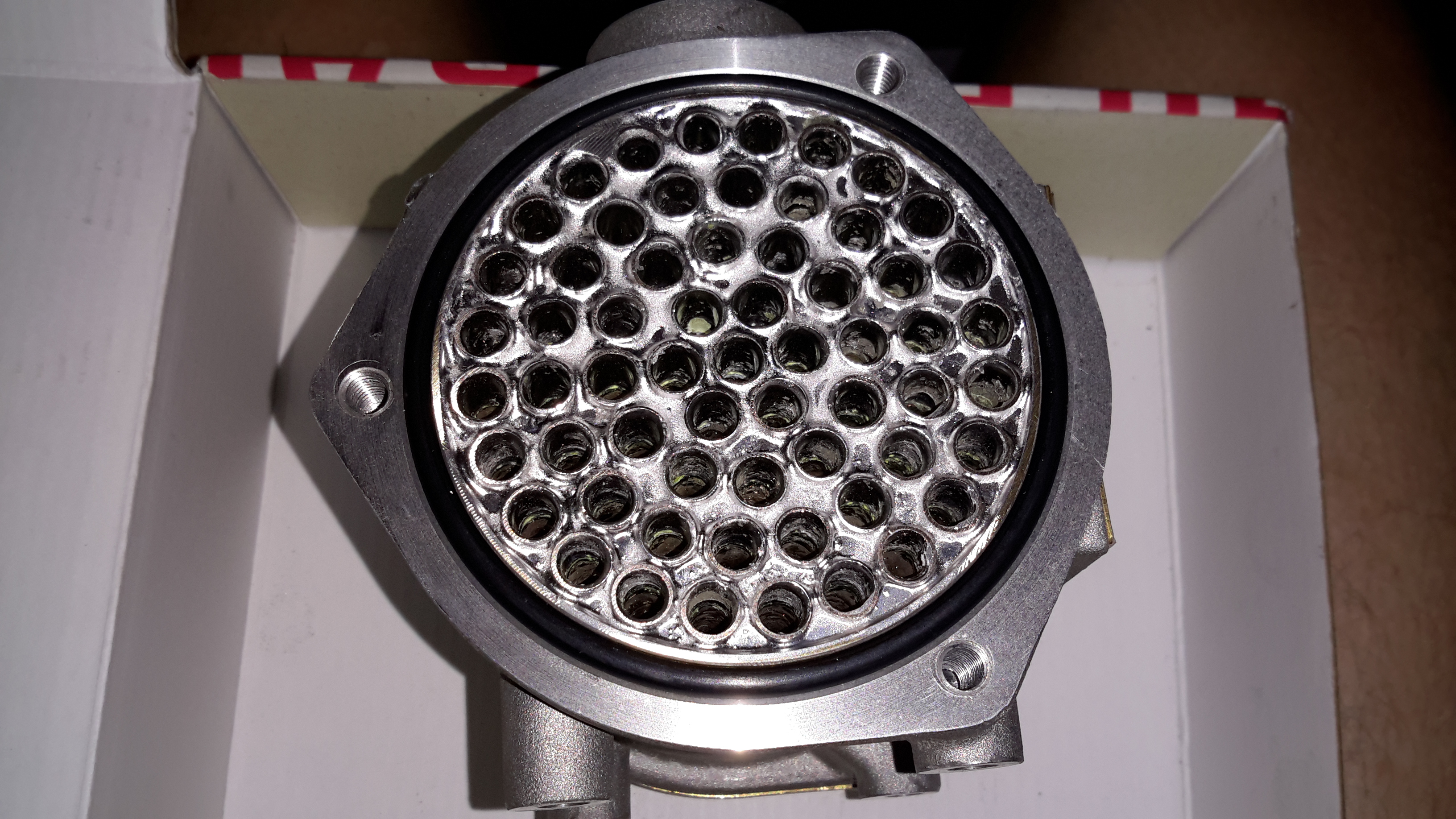
Tube End Plate
Unbolting the end cover reveals the brass tube end plate, soldered to all the core tubes in the cooler. An O-Ring at each end seals both the end cover & the interface between the tube plate & the outer casing.
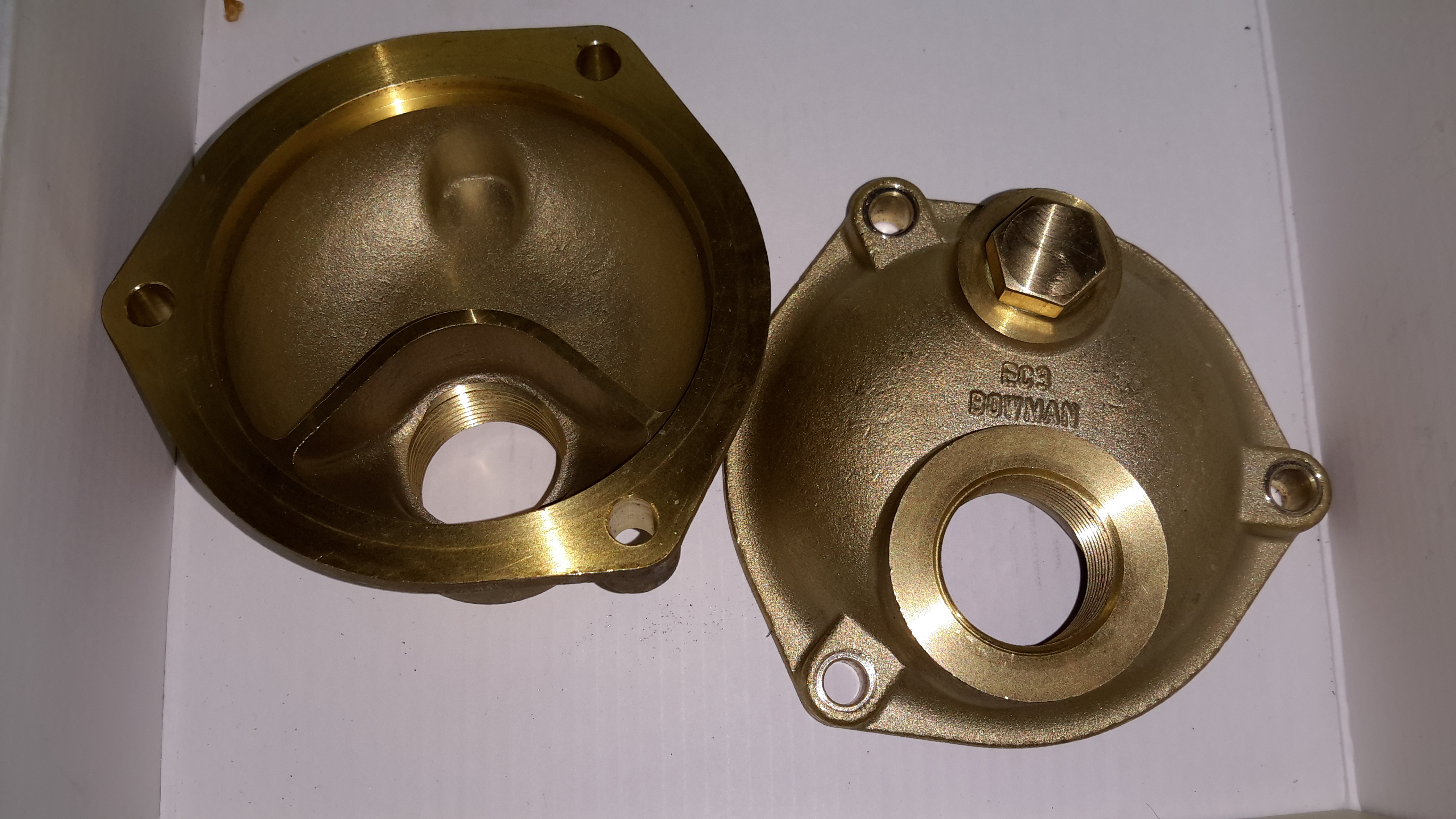
End Caps
The end caps have baffles cast in to direct the cooling water in a serpentine path, so the oil gets the best chance at dissipating it’s heat to the water.
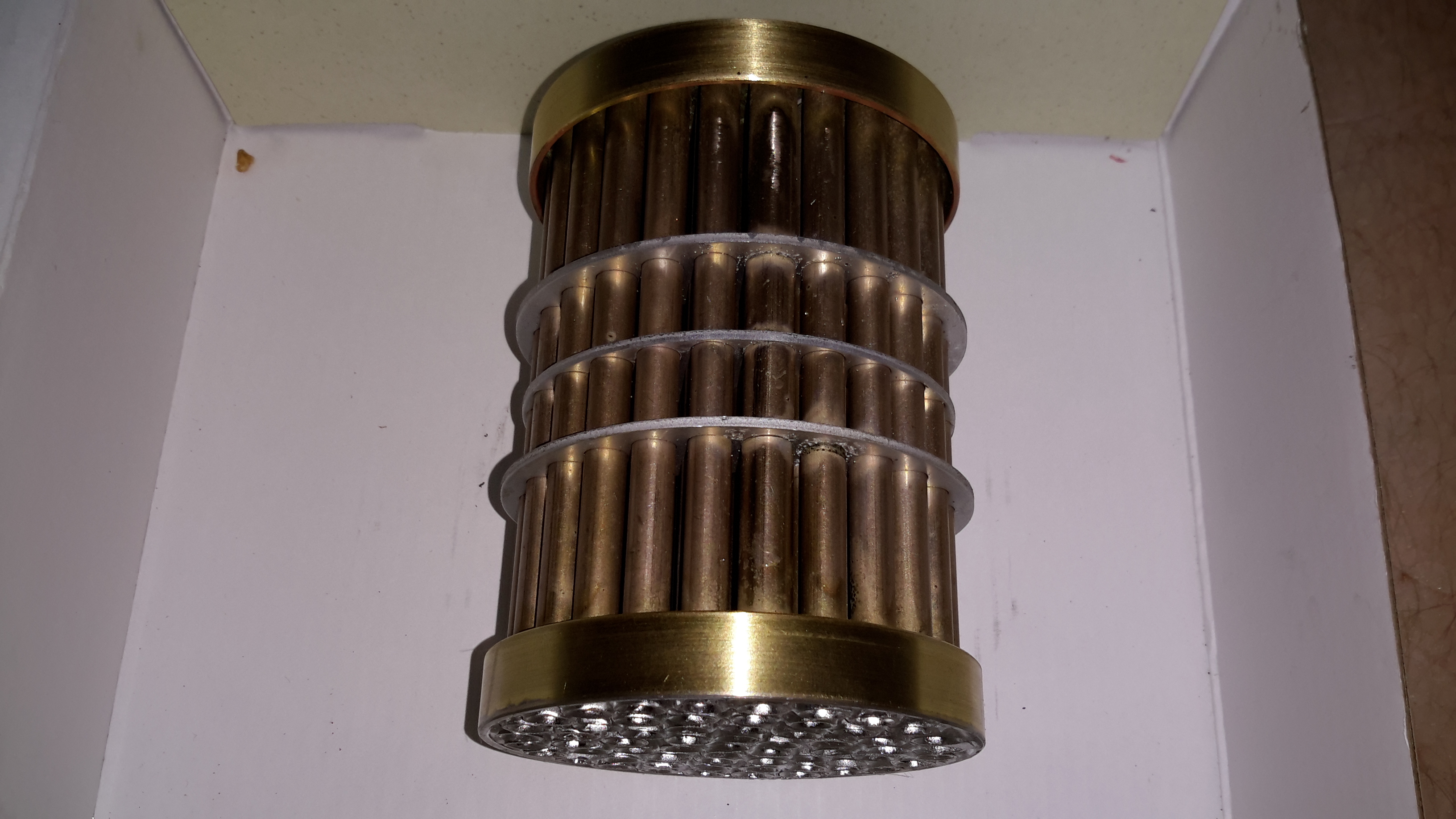
Tube Stack
The oil side of the system is on the outside of the tubes, again baffles placed along the stack direct the oil over the highest surface area possible.
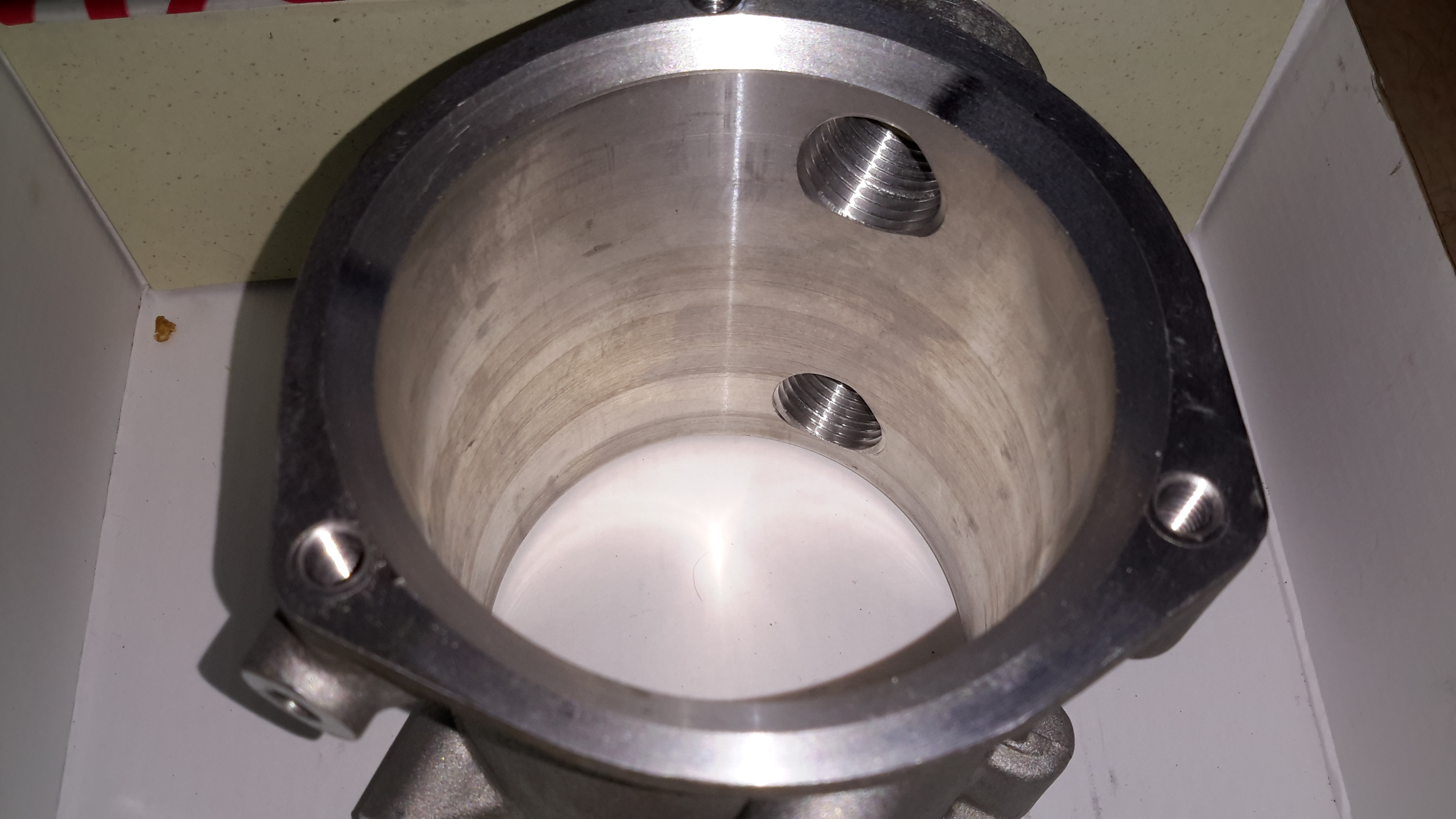
Outer Shell
The outer shell is just a machined alloy casting, with no internal features.
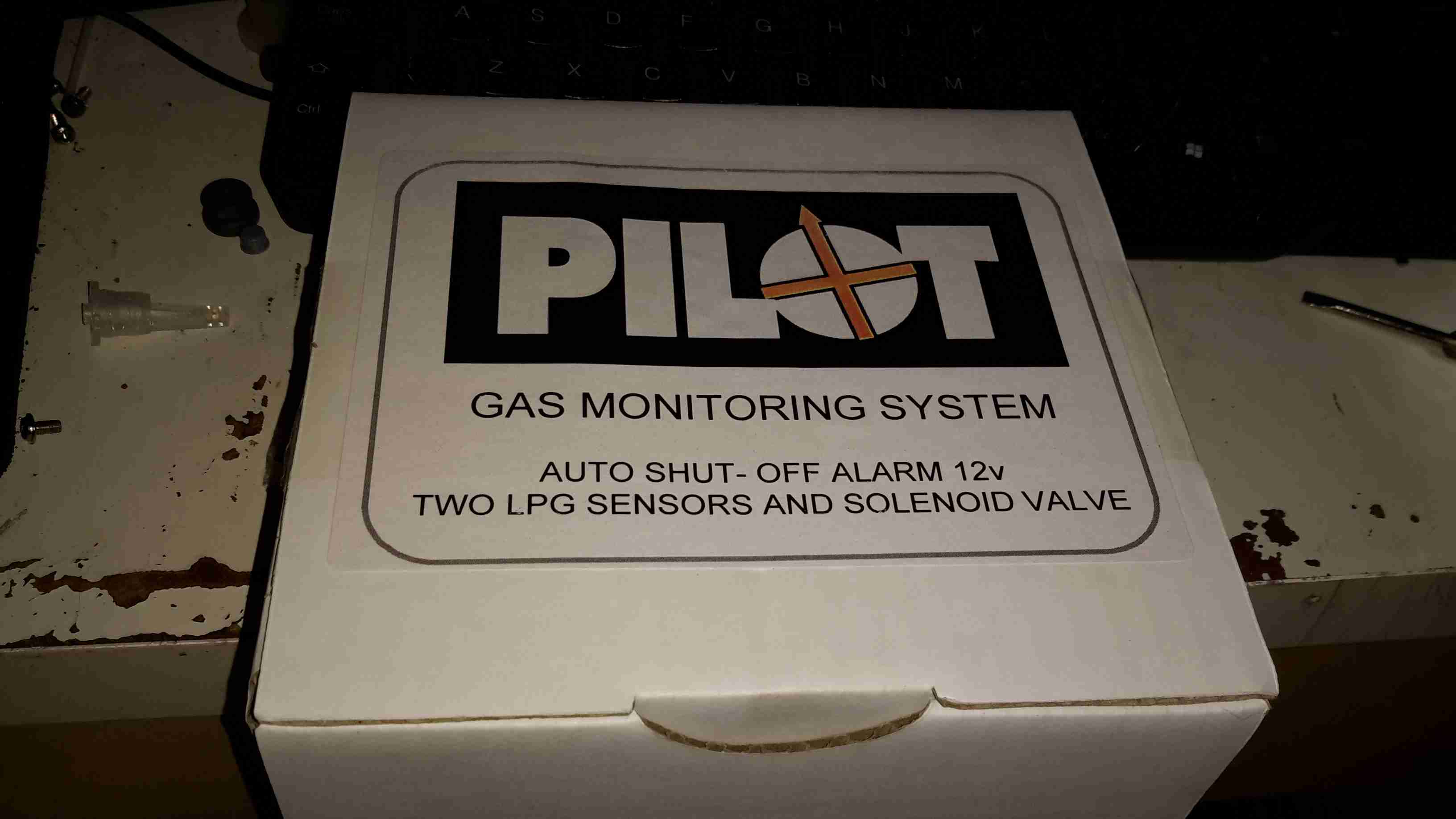
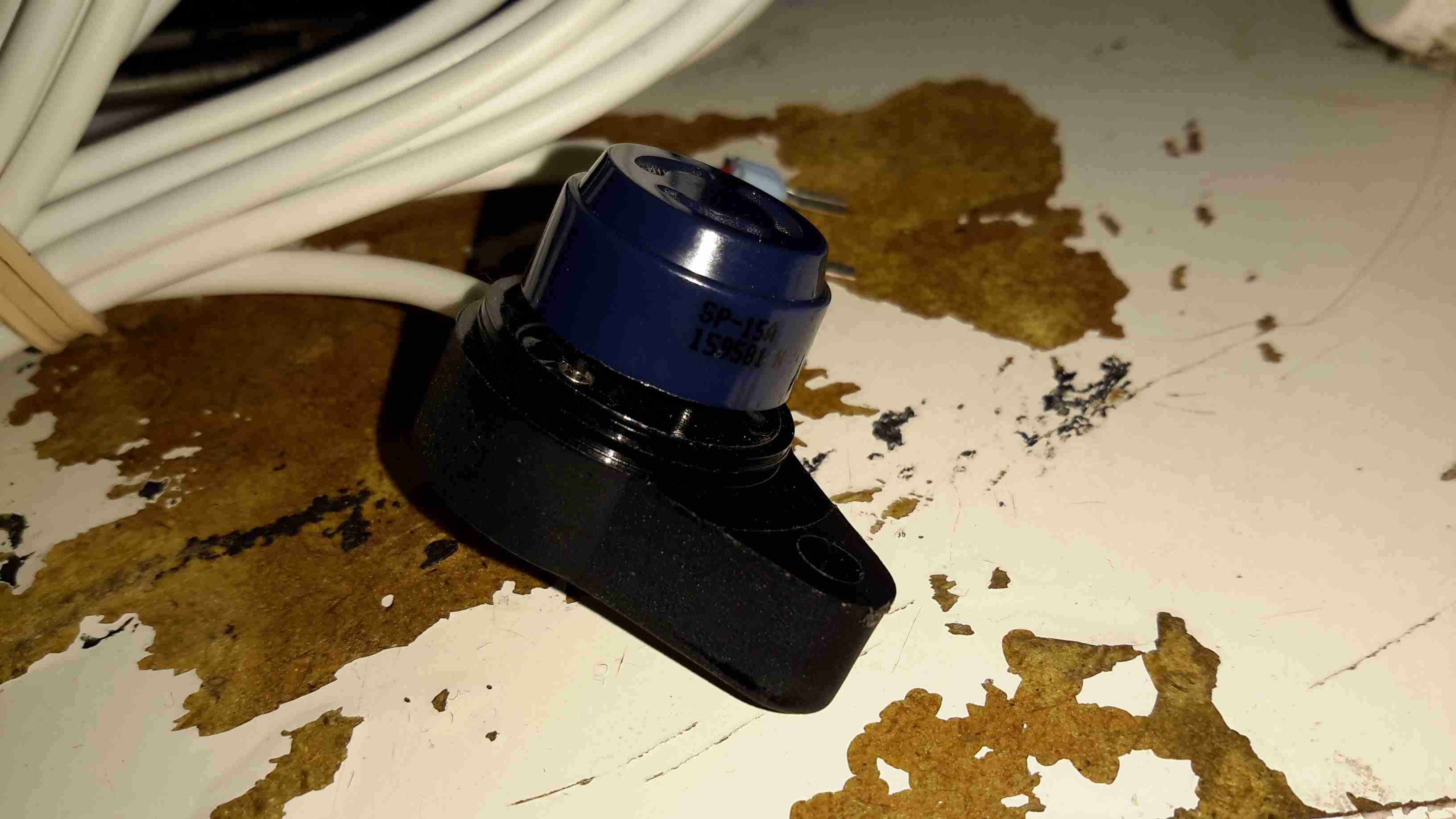
In my mind, the most dangerous thing onboard any boat is the LPG system, as the gas is heavier than air, any leaks tend to collect in the bilges, just waiting for an ignition source. To mitigate this possibility, we’re fitting a gas monitoring system that will sound an alarm & cut off the supply in case of a leak.
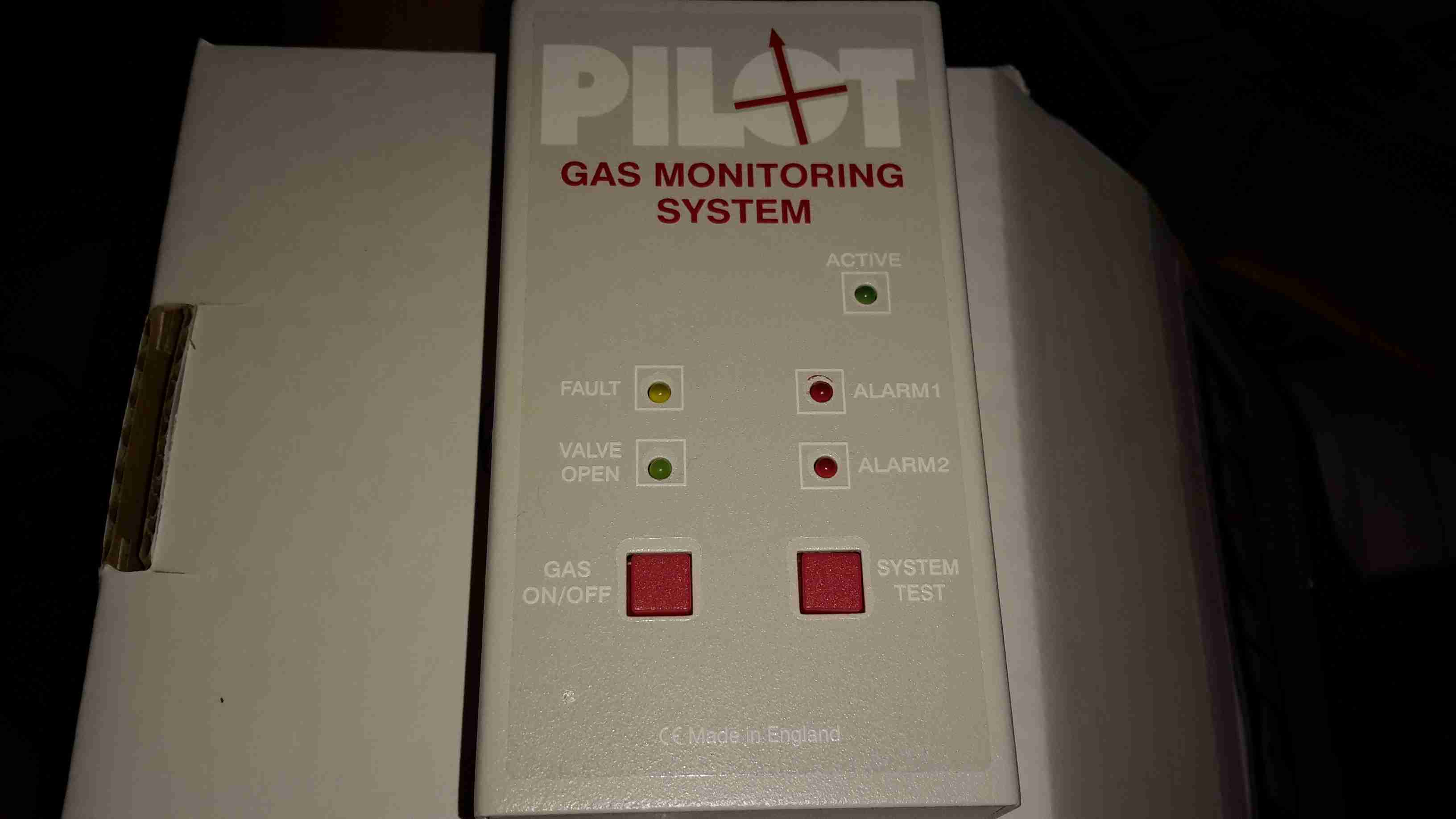
Monitor Unit
Here’s the monitor itself, the two sensor model. It’s nice & compact, and the alarm is loud enough to wake the dead.
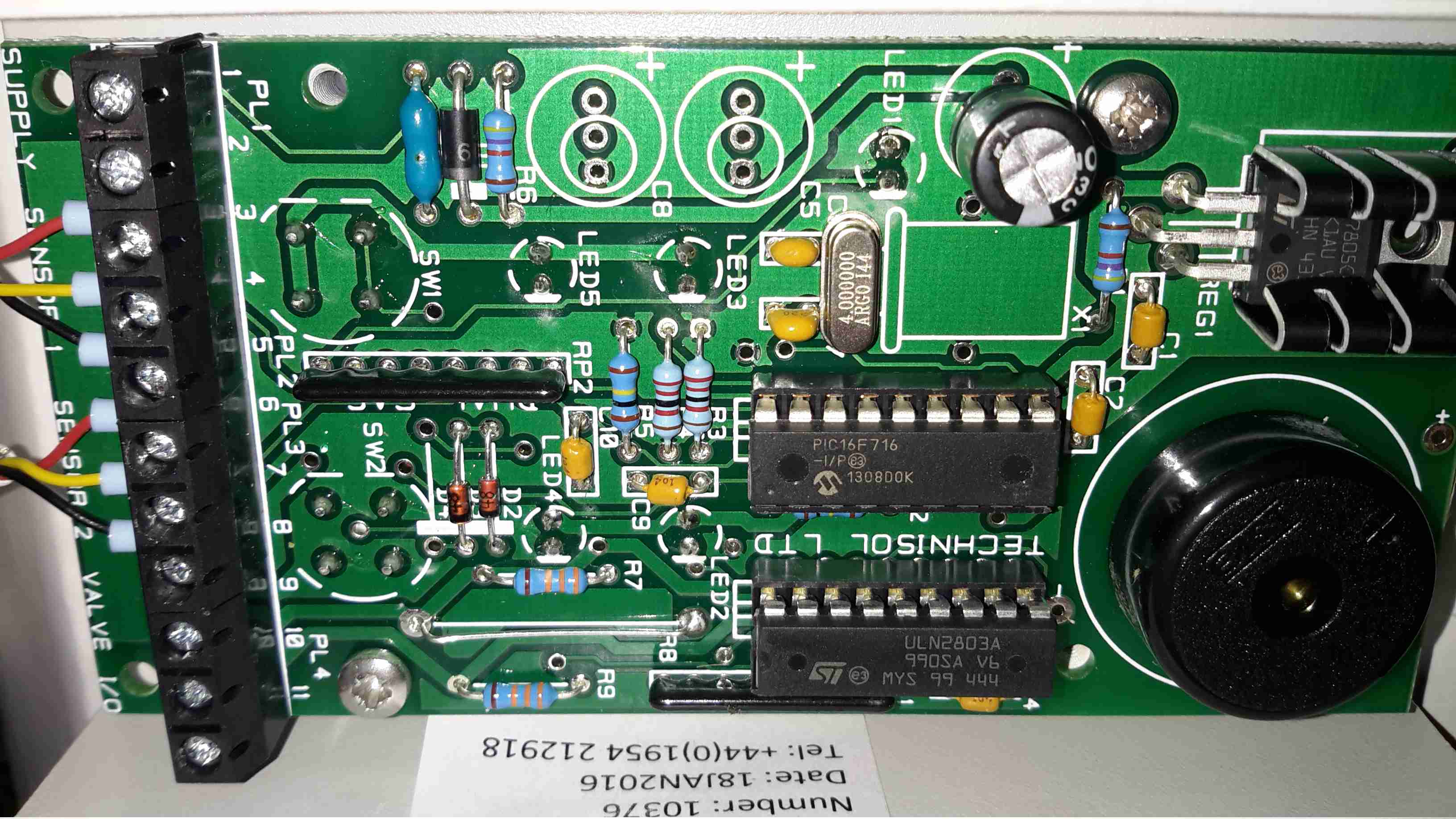
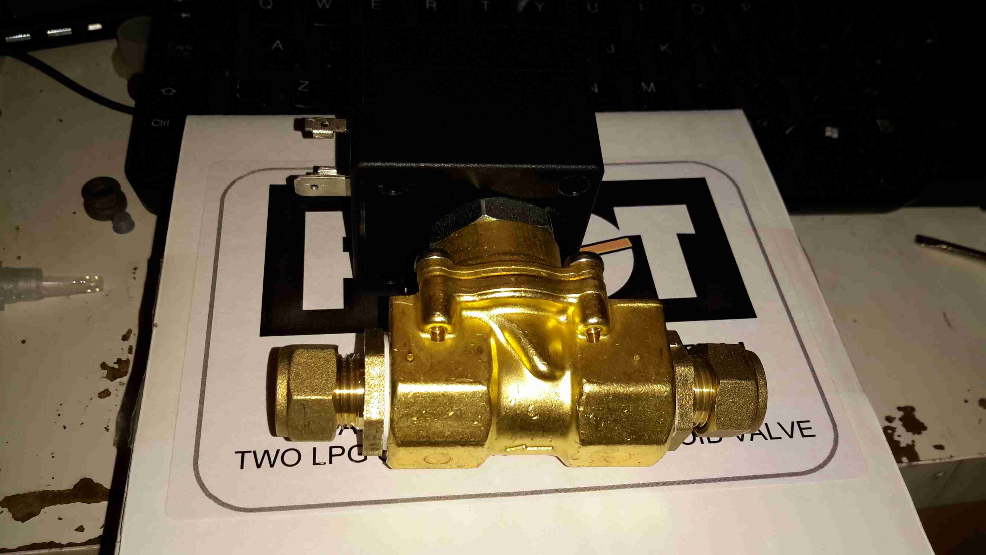
Control Board
Not much inside in the way of circuitry, the brains of the operation is a Microchip PIC16F716 8-bit microcontroller with an onboard A/D converter (needed to interface with the sensors), running at 4MHz. The solenoid valve is driven with a ULN2803 Darlington transistor array.
The alarm Piezo sounder can be seen to the right of the ICs, above that is a simple LM7805 linear regulator providing power to the electronics.
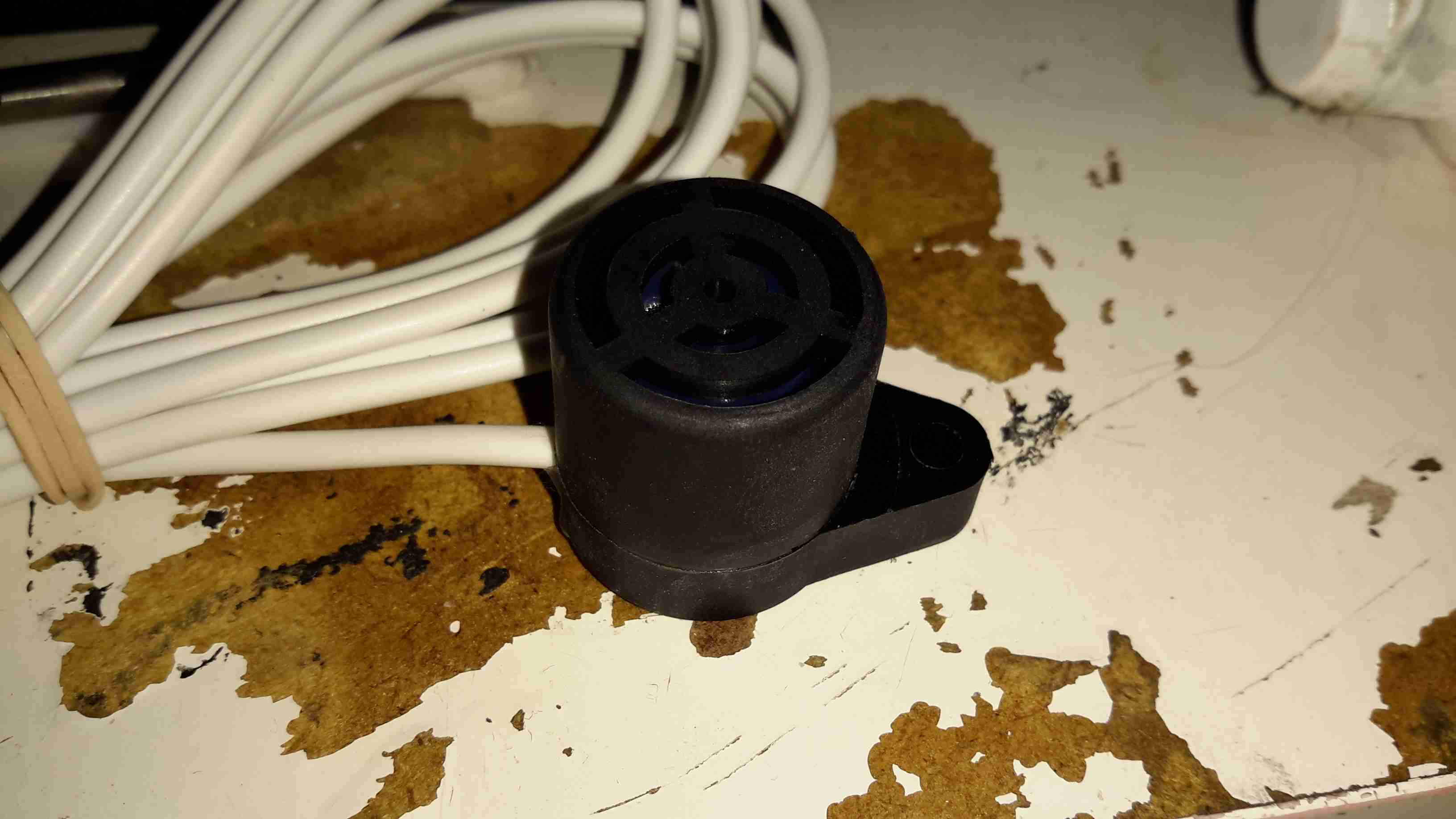
Remote Sensor
The pair of remote sensors come with 3.5m of cable, a good thing since the mounting points for these are going to be rather far from the main unit in our installation.
Sensor Element
The sensor itself is a SP-15A Tin Oxide semiconductor type, most sensitive to butane & propane. Unlike the Chinese El-Cheapo versions on eBay, these are high quality sensors. After whiffing some gas from a lighter at one of the sensors, the alarm triggered instantly & tripped the solenoid off.
Solenoid Valve
The solenoid valve goes into the gas supply line after the bottle regulator, in this case I’ve already fitted the adaptors to take the 10mm gas line to the 1/2″ BSP threads on the valve itself. This brass lump is a bit heavy, so support will be needed to prevent vibration compromising the gas line.
I’m no fan of power inverters. In my experience they’re horrifically inefficient, have power appetites that make engine starter motors look like electric toothbrushes & reduce the life expectancy of lead-acid batteries to no more than a few days.
However I have decided to do a little analysis on a cheapo “600W” model that Maplin Electronics sells.
Cover Removed
After a serious amount of metallic abuse, the bottom cover eventually came off. The sheet of steel used to close the bottom of the aluminium extrusion was wedged into place with what was probably a 10 ton hydraulic press.
As can be seen from the PCB, there’s no massive 50Hz power transformer, but a pair of high frequency switching transformers. Obviously this is to lighten the weight & the cost of the magnetics, but it does nothing for the quality of the AC output waveform.
DC Input End
The 12v DC from the battery comes in on very heavy 8-gauge cables, this device is fused at 75A!
DC Fuses
Here’s the fusing arrangement on the DC input stage, just 3 standard blade-type automotive fuses. Interestingly, these are very difficult to get at without a large hammer & some swearing, so I imagine if the user manages to blow these Maplin just expect the device to be thrown out.
Input DC-DC Switching MOSFETs
On the input side, the DC is switched into the pair of transformers to create a bipolar high voltage DC supply.
High Voltage Rectifiers
The large rectifier diodes on the outputs of the transformers feed into the 400v 100µF smoothing capacitors.
As mains AC is obviously a bipolar waveform, I’m guessing this is generating a ±150v DC supply.
Output MOSFETs
After the high voltage is rectified & smoothed, it’s switched through 4 more MOSFETs on the other side of the PCB to create the main AC output.
The label states this is a modified-sine output, so I’d expect something on the scope that looks like this:
Inverter Waveforms
Modified-sine doesn’t look as bad as just a pure square output, but I suspect it’s a little hard on inductive loads & rectifiers.
However, after connecting the scope, here’s the actual waveform:
Actual Waveform
It’s horrific. It’s not even symmetrical. There isn’t even a true “neutral” either. The same waveform (in antiphase) is on the other mains socket terminal. This gives an RMS output voltage of 284v. Needless to say I didn’t try it under load, as I don’t possess anything I don’t mind destroying. (This is when incandescent lamps are *really* useful. Bloody EU ;)).
About the only thing that it’s accurate at reproducing is the 50Hz output, which it does pretty damn well.
System Microcontroller
As is usual these days, the whole system is controlled via a microcontroller.
This is basically an industrial, rugged MP3 player, in an extruded aluminium case.
They are used in commercial settings for generating telephone hold music or continual playback of background music in shops.
USB1100
It’s quite a compact unit, in a nice aluminium case, designed for mounting into a comms setup. This unit will play any MP3 file, up to a maximum size of 11MB.
Connections
Here’s the user connections on the end of the unit. The device takes a standard 12v DC input, and has a single button for setup, user feedback is given through the multi-colour LED next to the power jack.
Both 8Ω & 600Ω audio outputs are provided for maximum compatibility. Volume & tone controls are also here.
On the other end of the unit is a single USB port for loading the audio files from a USB drive, and a reset button.
Main PCB
Here’s the single PCB removed from the casing. Unfortunately the main CPU has had it’s part number sanded off, and I can’t be bothered to try & find out what kind of processor it is at this point. To the right of the CPU are some flash ROM & SDRAM, along with the single USB port at bottom right.
The left side of the board is dedicated to audio output & voltage regulation, there are a fair few linear regulators in this unit.
Audio End
Here’s the audio output side of the board, the transformer on the left is to provide the 600Ω output, the audio amplifier IC (BA5416) is just behind it. To the right are some of the main voltage regulators, a 5v one on the heatsink & a LM317.
Audio Codec
The audio codec is a CS4271 from Cirrus Logic, a really high quality part, 24-bit resolution, 192kHz Stereo codec. Considering this is for telephone & PA systems that aren’t that high fidelity, it’s well built!
Here’s an odd & sudden failure, the power adaptor for a Samsung device. It’s been working for months & on being plugged into the mains today the magic blue smoke escaped.
Samsung Charger
It’s one of their 2A models, for charging bigger devices like tablets.
Flash Burn
Strangely for one of these chargers, no glue is used to hold it together – just clips. This made disassembly for inspection much easier. Evidence of a rather violent component failure is visible inside the back casing.
PCB
Here’s the charger PCB removed from the casing. As to be expected from Samsung, it’s a high quality unit, with all the features of a well designed SMPS.
PCB Reverse
However, on turning the board over, the blown component is easily visible. It’s the main SMPS controller IC, with a massive hole blown in the top. The on board fuse has also blown open, but it obviously didn’t operate fast enough to save the circuit from further damage!
I recently ordered a PSU to run one of the TVs I converted to 12v operation, and being an older TV, it’s a fairly heavy load at 6.5A. eBay to the rescue again, with a cheap 10A rated supply.
Power Brick
Like all similar supplies these days, it’s a SMPS unit, and feels suspiciously light for it’s power rating.
Cover Removed
Luckily this one is easy to get into, no ultrasonic welding on the case, just clips. Here’s the top cover removed, big alloy plate between the heatsinks.
PCB
The top heatsink plate was glued to the top of the transformer with silicone, some gentle prying released it. From the top, things don’t look too bad. There’s some filtering on the mains input & it’s even fused!
Primary Side
Here’s a closeup of the primary side of the PSU, the main DC bus capacitor is a Nichicon one, but it’s clearly been recovered from another device, look at the different glue on the end!
it’s also flapping about in the breeze, the squirt of silicone they’ve put on does nothing to stop movement.
Also here is the mains input fuse, filter capacitor & common mode choke. At least there is some filtering!
The main control IC is a UC3843B High Performance Current Mode PWM Controller, operating at a switching frequency of 250kHz.
The main switching transistor is visible at the bottom left corner, attached to the heatsink.
Secondary Side
Here’s the secondary side of the supply. The transformer itself is OK, nice heavy windings on the output to suit the high current.
It’s using proper opto-isolated feedback for voltage regulation, with a TL431 reference IC.
The output diodes are attached to the heatsink at the top of the photo, I couldn’t read any numbers on those parts.
The output filter capacitors are low quality, only time will tell if they survive. I’ll put the supply under full load & see what the temperature rise is inside the casing.
PCB Bottom
On the bottom of the PCB things get a little more dire. There isn’t really much of an isolation gap between the primary & secondary sides, and there’s a track joining the output negative with mains earth, which gets to within 2mm of the live mains input!
As with all these cheapo supplies, there’s good points & bad points, I will update when I’ve had a chance to put the supply under full load for a while & see if it explodes!
I recently dug out my other card printer to fit it with a 12v regulator, (it’s 24v at the moment), and figured I’d do a teardown post while I had the thing in bits.
This is a less industrial unit than my Zebra P330i, but unlike the Zebra, it has automatic duplexing, it doesn’t have Ethernet connectivity though.
Unlike domestic printers, which are built down to a price, these machines are very much built up to a spec, and feature some very high quality components.
Naked Printer
Here’s the mechanism with the cowling removed. This is the main drive side of the printer, with the main drive stepper at left, ribbon take-up spool motor lower right, and the duplex module stepper motors at far right.
Main Motor Drive
The main drive motor runs the various rollers in the card path through a pair of synchronous belts, shown here.
Main Stepper
The stepper itself is a quality ball-bearing Sanyo Denki bipolar motor.
Main Stepper Driver
Electrical drive is provided to the stepper with a L6258EX DMOS universal motor driver. This chip can also drive DC motors as well as steppers.
Ribbon Supply Spool
Here is the encoder geared onto the ribbon supply spool. This is used to monitor the speed the ribbon is moving relative to the card.
Printer Top
Here’s a top view through the printer, the blue roller on the left cleans the card as it’s pulled from the feeder, the gold coloured spool to it’s right is the ribbon supply reel. The cooling fan on the right serves to stop the print head overheating during heavy use.
Spool Take Up Motor
The spool take-up reel is powered by another very high quality motor, a Buhler DC gearmotor. These printers are very heavily over engineered!
This motor drives the spool through an O-Ring belt, before the gear above. This allows the drive to slip in the event the ribbon jams, preventing it from breaking.
Duplex Unit Stepper Drivers
The pair of steppers that operate the duplexing unit are driven by a separate board, with a pair of L6219DS bipolar stepper driver ICs. There are also a couple of opto-sensors on this board for the output hopper.
Main Control PCB
All the mechanisms of the printer are controlled from this main PCB, which handles all logic & power supply functions. Sections on the board are unpopulated, these would be for the Ethernet interface, smart card programming & magstripe programming.
Main CPU
The brains of the operation is this ColdFire MCF5208CVM166 32-bit microprocessor. It features 16KB of RAM, 8KB of cache, DMA controller, 3 UARTs, SPI, 10/100M Ethernet and low power management. This is a fairly powerful processor, running at 166MHz.
It’s paired with an external 128Mbit SDRAM from Samsung, and a Spansion 8Mbit boot sector flash, for firmware storage.
USB Interface & Power Input
Here the USB interface IC is located. It’s a USBN9604 from Texas Instruments, this interfaces with the main CPU via serial.
A while ago I blogged about modifying the output voltage of some surplus Cisco switch power supplies to operate at 13.8v.
Since I was able to score a nice Hammond 1598DSGYPBK ABS project box on eBay, I’ve built one of the supplies into a nice bench unit.
Hammond ABS CaseSupply Unit
Above is the supply mounted into the box, I had to slightly trim one edge of the PCB to make everything fit, as it was just a couple of mm too wide. Luckily on the mains side of the board is some space without any copper tracks.
PSU Fan
These supplies are very high quality & very efficient, however they came from equipment that was force-air cooled. Running the PSU in this box with no cooling resulted in overheating. Because of this I have added a small 12v fan to move some air through the case. The unit runs much cooler now. To allow the air to flow straight through the case, I drilled a row of holes under the front edge as vents.
Output Side
Here is the output side of the supply, it uses standard banana jacks for the terminals. I have used crimp terminals here, but they are soldered on instead of crimped to allow for higher current draw. The negative return side of the output is mains earth referenced.
I have tried to measure output ripple on this supply, but with my 10X scope probe, and the scope set to 5mV/Div, the trace barely moves. The output is a very nice & stable DC.
This supply is now running my main radio in the shack, and is small enough to be easily portable when I move my station.
Recently I’ve noticed my usual mobile rig, the Baofeng UV-5R, has had very poor receive, and non-existent transmit.
I did a power test on the radio, and confirmed it was still outputting it’s rated RF power. Trying another antenna proved that the radio was fine.
Time to tear down the antenna & see if it can be fixed!
Stock Antenna
Here’s the antenna, just the factory rubber duckie. As with all these antennas, they’re a compromise between size & their efficiency.
Naked Antenna!
Giving a gentle pull to the antenna sheath while it’s attached to the radio allows it to come apart. The quality actually doesn’t look to bad. It’s very similar in construction to my Diamond X-30, just on a much smaller scale.
At the bottom of the antenna is the matching network, an inductor & ceramic disc capacitor. Here lies the problem with this antenna.
Dry Joint
Here where the capacitor joins onto the feedpoint from the SMA connector, the solder joint has come away. This was a very poor joint to start with, and the solder hadn’t wetted the capacitor lead at all
After cleaning the joint, and applying some flux, a new joint was easily made with some Real Solder.
Repaired Joint
Here’s the joint freshly repaired, the antenna is now back to full working order. It even seems to work better than the others I have 🙂
After running on handies for all of my Ameteur Radio life, I figured it was time for a new radio, this time a base station/mobile rig, & after some looking around I decided on the Wouxun KG-UV950P.
Shown below is the radio as delivered:
Wouxun Boxed
This radio has the capability to transmit quad-band, on 6m, 10m, 2m & 70cm. It also has the capability to receive on no fewer than eight bands. Also included in the feature set is airband receive, & broadcast FM receive.
TX power is up to 50W on 2m, 40W on 70cm, & 10W on 6m/10m.
Opened
For once with a Chinese piece of electronic equipment, the manual is very well printed, and in very good English.
Radio Operating
Here is the radio in operation, connected to my 65A 12v power supply. I have the radio set here monitoring a couple of the local 70cm repeaters.
The display is nice & large – easy to see at a glance which station you’re tuned to. The backlight is also software settable to different colours.
Status indicators on the top edge of the display can be a bit difficult to see unless the panel is directly facing the user though, not to mention that they are rather small.
This radio is true dual-watch, in that both VFOs can be receiving at the same time, this is effected by a pair of speakers on the top panel:
Speakers
The left VFO speaker is smaller than the right, so the sound levels differ slightly, but overall sound quality is excellent. There is also provision on the back of the unit to connect external speakers.
The dual volume controls on the right hand bottom corner of the control panel are fairly decent, if a little twitchy at times. There is also a fair amount of distortion on the audio at the higher volume levels.
The controls themselves are potentiometers, but the controller appears to read the setpoint with an ADC – this means that if the control is set to just the right point, the selected level will jump around on the display & never settle down.
The radio itself is built from a solid aluminium casting, mostly for heatsinking of the main RF output stage MOSFETs. This gives the radio a very rugged construction.
A small fan is provided on the rear for cooling when required. This can be set in software to either be constantly running, (it’s pretty much silent, so this is advantageous), or only run when in TX mode. The fan will also automatically come on when a high internal temperature is detected.
Hand Mic
Here is the microphone. Like the main unit of the radio this is also very solidly built, fits nicely in the hand & the PTT has a nice easy action, which helps to prevent straining hands while keeping the TX keyed.
Conveniently, all of the controls required to operate the radio are duplicated on this mic, along with a control lock switch, & backlighting for the buttons.
Another Speaker
Another output speaker is placed in the back of the mic. This one can be activated through the menu system, to either use the main body speakers, the mic mounted one, or both.
A mounting hook for the mic is provided to attach to any convenient surface.
Radio Back
Here’s the back of the radio, with some of the big heatsink fins, the fan in the centre. To the left is the PL259 RF output, this looks to be a high quality Teflon insulated one. On the right are the power input leads & the external speaker outputs.
External Speaker Sockets
The external speaker connections are via 3.5mm jacks. I haven’t yet tested this feature.
Remote Mounting Plate
The control panel of this radio is detachable from the main body, and a pair of adaptors are provided. This either allows the radio display to be angled upwards toward the user, set parallel, or even mounted remotely. A control extension cable is provided to allow the main body to be mounted a fair distance away.
External Interface Connectors
On the left of the radio is the PC control & programming port, & the mic connector. Wouxun *really* like RJ-45 connectors, they’ve used them for everything on this radio.
Also visible here is the tilted faceplate adaptor.
The supplied software to program the radio, while functional, is absolutely horrific. Hopefully someone will add support for this radio into CHIRP. Anything would be an improvement in this area.
Everything considered, I like this radio. It’s very solidly built, easy to use, and sounds brilliant.
TX audio is great, (or so my other contacts tell me).
Unsurprisingly, the unit gets warm while transmitting, however on high power, it does get uncomfortably warm, and the built in fan does little in the way of helping when a long QSO is in progress. I may remedy this at some stage with a more powerful fan. A little more airflow would do wonders.
If the programming software was built as well as the radio, I’d have zero serious complaints.
At full power, the radio pulls ~10A from the power supply, at 12.9v DC.
As for the antenna I’m currently using, it’s a Diamond X30, mounted on a modified PA speaker stand, at ~30 feet above ground. The feeder is high quality RG-213.
TX Antenna
When I manage to get the set disconnected, a partial teardown will be posted, with some intimate details about the internals. Stay tuned!
I recently managed to score a 3″ B&W portable TV on eBay, a Panasonic TR-3000G. As these old units are now useless, thanks to the switch off of analogue TV signalling, I figured I could find a composite signal internally & drive the CRT with an external source.
Panasonic TR-3000G
Here’s the TV in it’s native state. Running from 9v DC, or 6 D size cells. I’m guessing from somewhere around the 1970’s. Here is the CRT & associated drive circuitry, removed from the casing:
CRT Module
After dissecting the loom wiring between the CRT board & the RF/tuner board, I figured out I had to short out Pins 1,2 & 5 on the H header to get the CRT to operate straight from the power switch. This board also generates the required voltages & signals to drive the RF tuner section. I have removed the loom from this, as the PCB operates fine without. It doesn’t seem to be fussy about power input either: it’s specified at 9v, but seems to operate fine between 7.5v & 14.5v DC without issue.
Video Connections
Tracing the wiring from the tuner PCB revealed a length of coax snaking off to the section marked Video/Sync. I successfully found the composite input!
Running OSMC
A quick bit of wiring to a Raspberry Pi, & we have stable video! For such an old unit, the picture quality is brilliant, very sharp focus.
Matsushita 85VB4 CRT
Closeup of the CRT itself. I haven’t been able to find much data on this unit, but I’m guessing it’s similar to many commercial viewfinder CRTs.
Electron Gun Closeup
Amazingly, there isn’t a single IC in the video circuitry, it’s all discrete components. This probably accounts for the large overall size of the control PCB. Viewfinder CRTs from a few years later on are usually driven with a single IC & a few passives that provide all the same functions.
As the cable supplied with the panel is far too short, inflexible & does not even allow the cable gland on the terminal box to form a seal, I have replaced it with some high quality twin core guitar cable, with silicone insulation.
The cable is removable from the panel tail by means of a screwlock two pin connector.
On another note, I have noticed a side effect of fitting a switchmode regulator to the panel: it seems to have formed an MPPT-type regulator setup, as even in low light conditions, when the bare panel is outputting 18.5v at 50mA short circuit, with the switching regulator I can get a useable 13.25v at ~170mA.
This effect is increased in full light, where I can obtain 4.5A short circuit current & ~1.8A at 13.25v output.
Tip Jar
If you’ve found my content useful, please consider leaving a donation by clicking the Tip Jar below!
All collected funds go towards new content & the costs of keeping the server online.