I did a little more digging into the PSU circuitry of the small coin counting machine, and it’s even more strange than I thought!
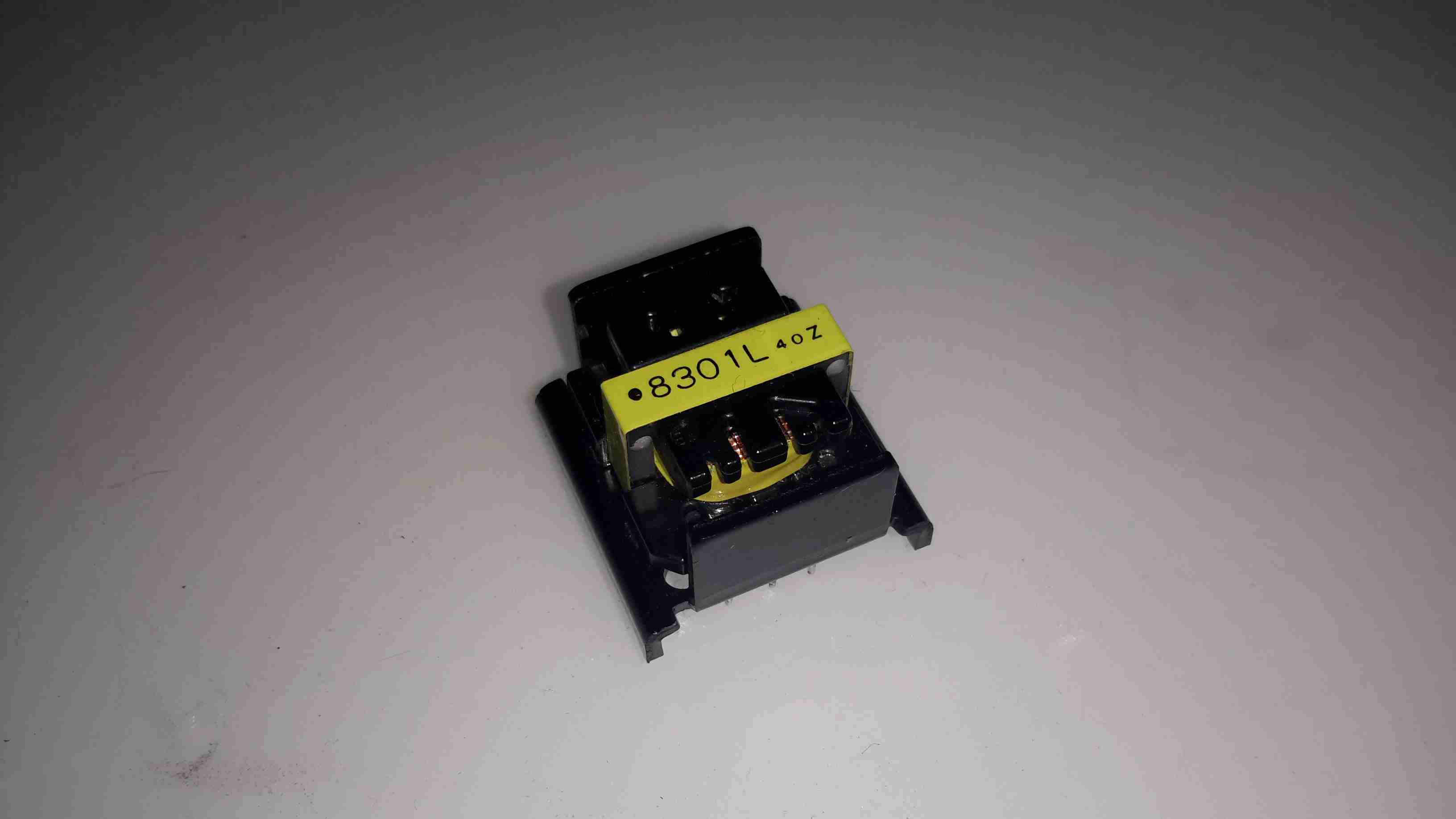
The part I originally thought was a transformer on the PSU board is in fact a DC-DC converter module!
DC-DC Converter
Here’s the device after desoldering it from the PCB. It turns out that instead of a transformer, it’s an inductor.
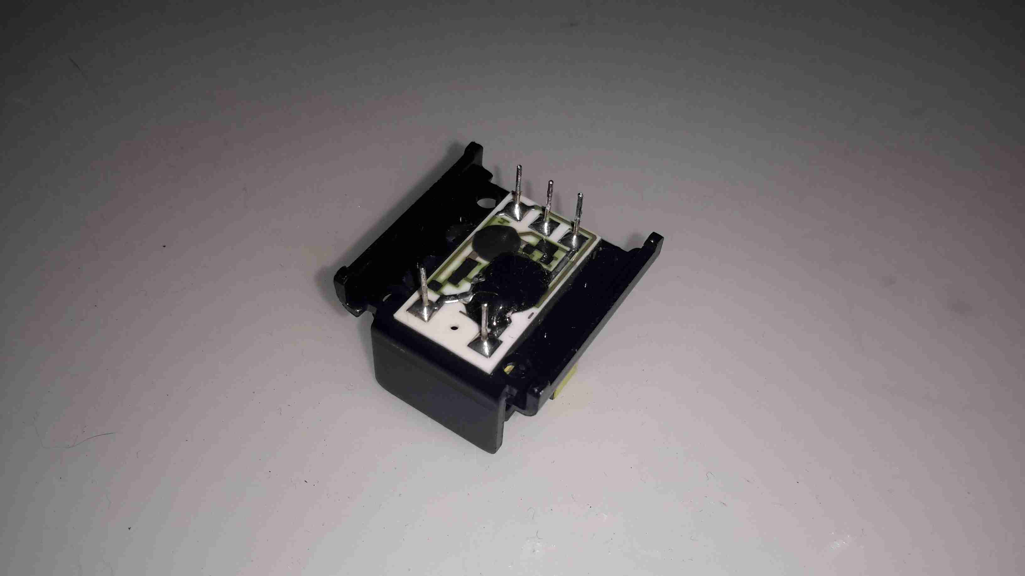
Hiding Control Electronics
Underneath is the controller electronics, with an COB controller & the switching transistors are under a protective covering of silicone.
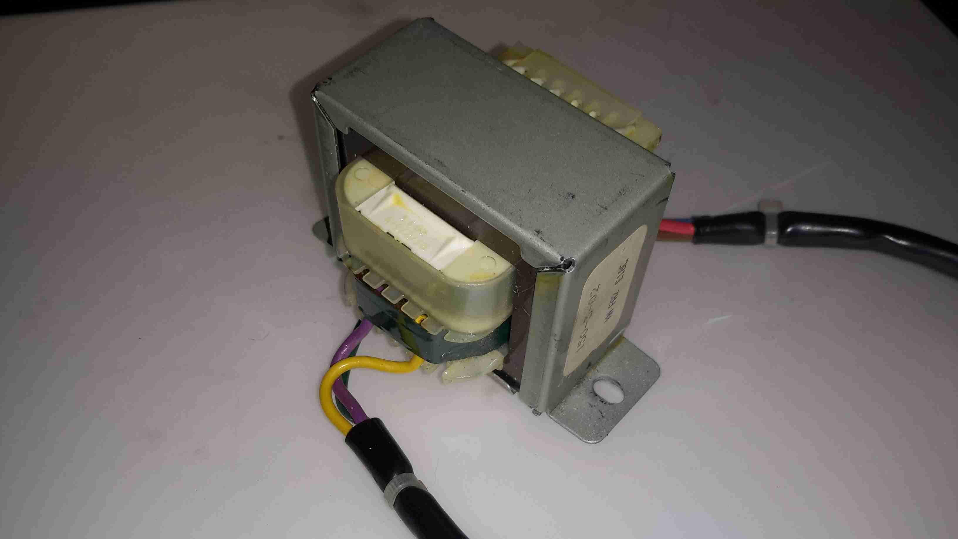
Mains Transformer
Driving this whole lot of PSU randomness is the mains transformer, with a secondary voltage of 35v.
The only reason I can think of that the manufacturer went to this much expense with the power supply is stability – a coin counting machine that miscounts due to power supply surges, sags & spikes wouldn’t be very much use. It’s not likely I’ll see anything similar again, unless I manage to get hold of something like medical grade equipment.
Here’s some teardown photos of an old De La Rue coin counter, used in businesses for rapid counting of change into large bags.
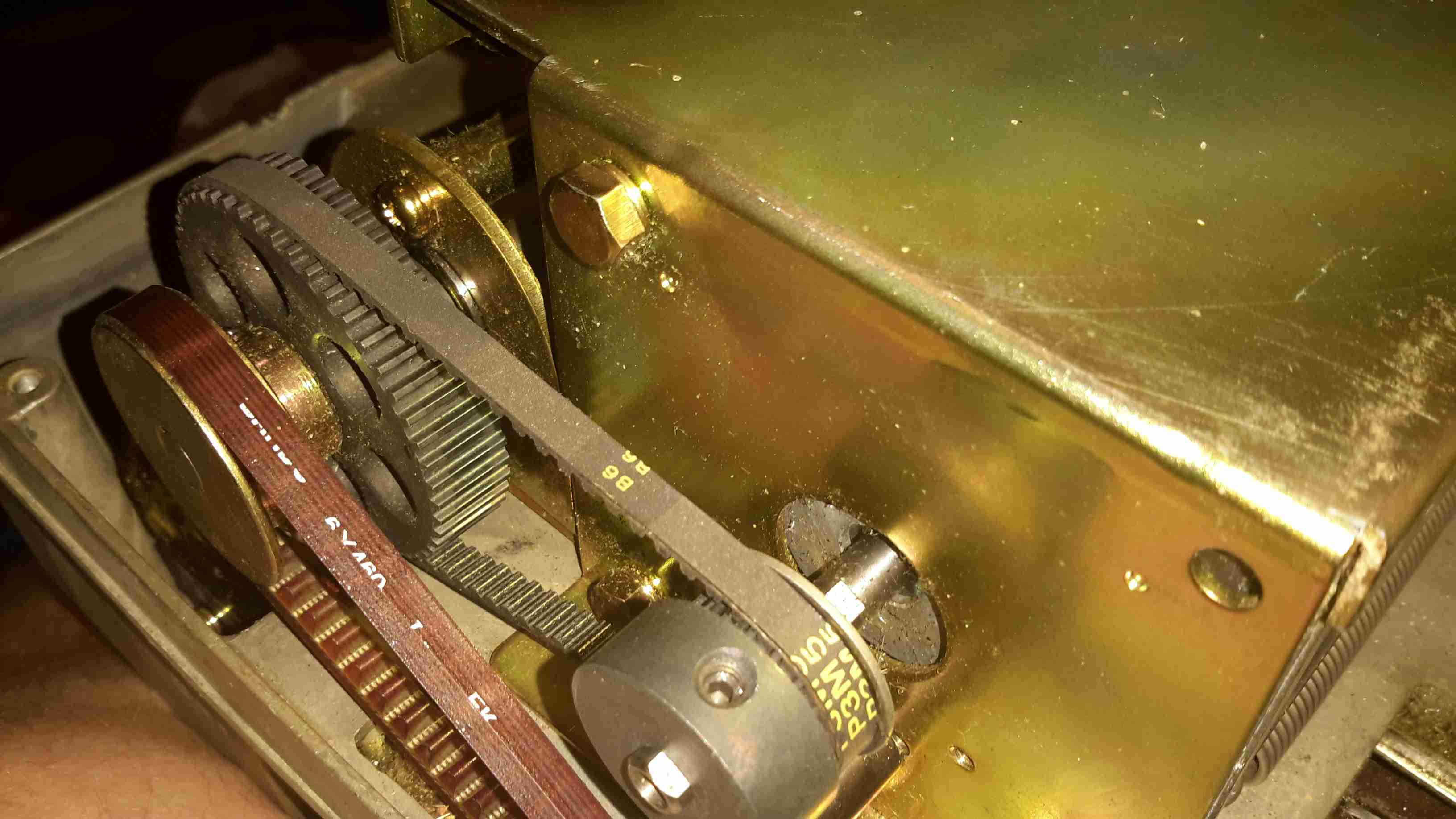
Mechanism
An overview of the whole mechanical system of the counter. Coins are loaded into the drum at the rear of the machine, which sorts them into a row for the rubber belt to pick up & run through the counter. The coin type to be sorted is selected by turning the control knobs on the right.
The control knobs adjust the width & height of the coin channel so only the correct sized coins will be counted.
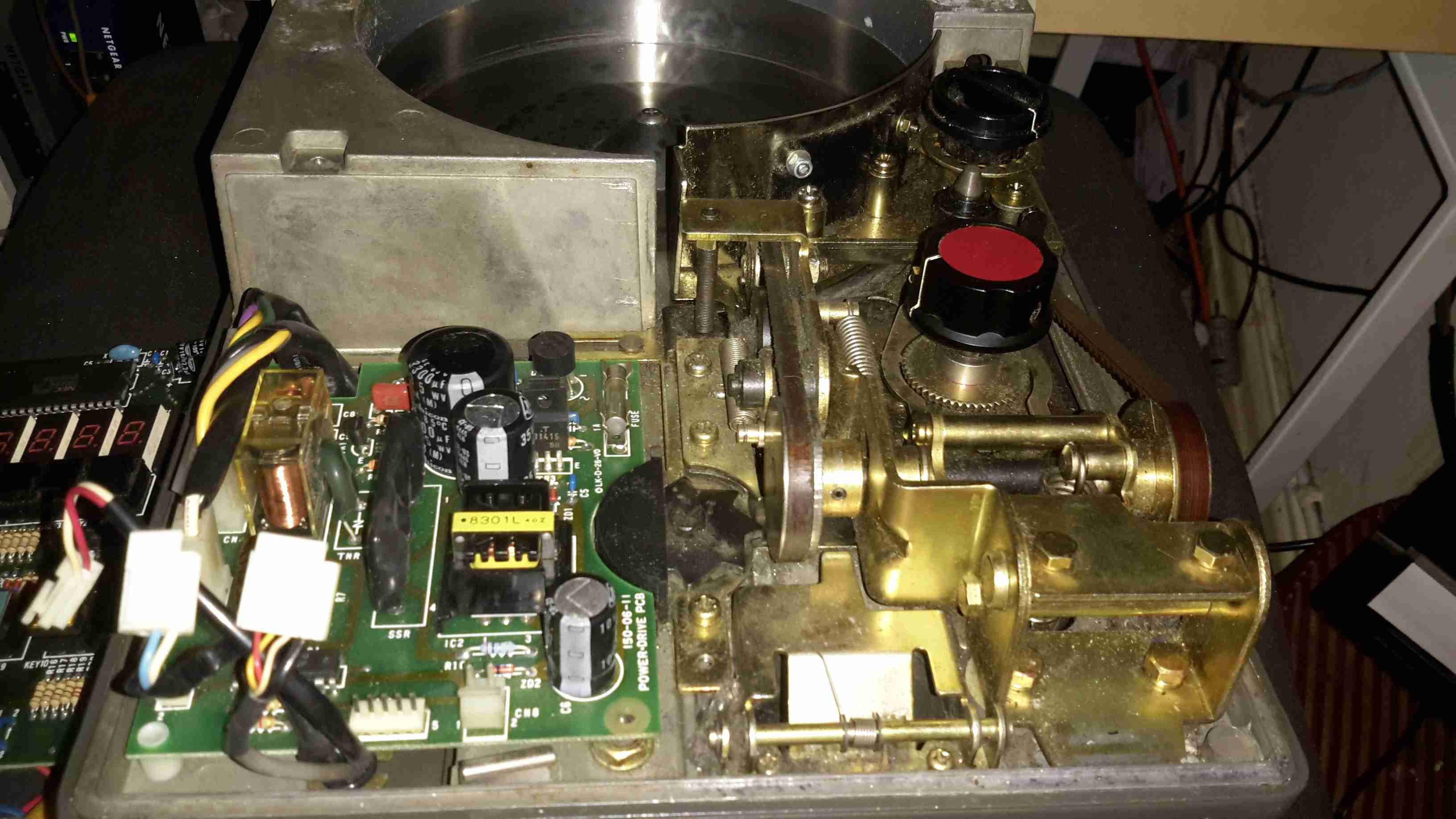
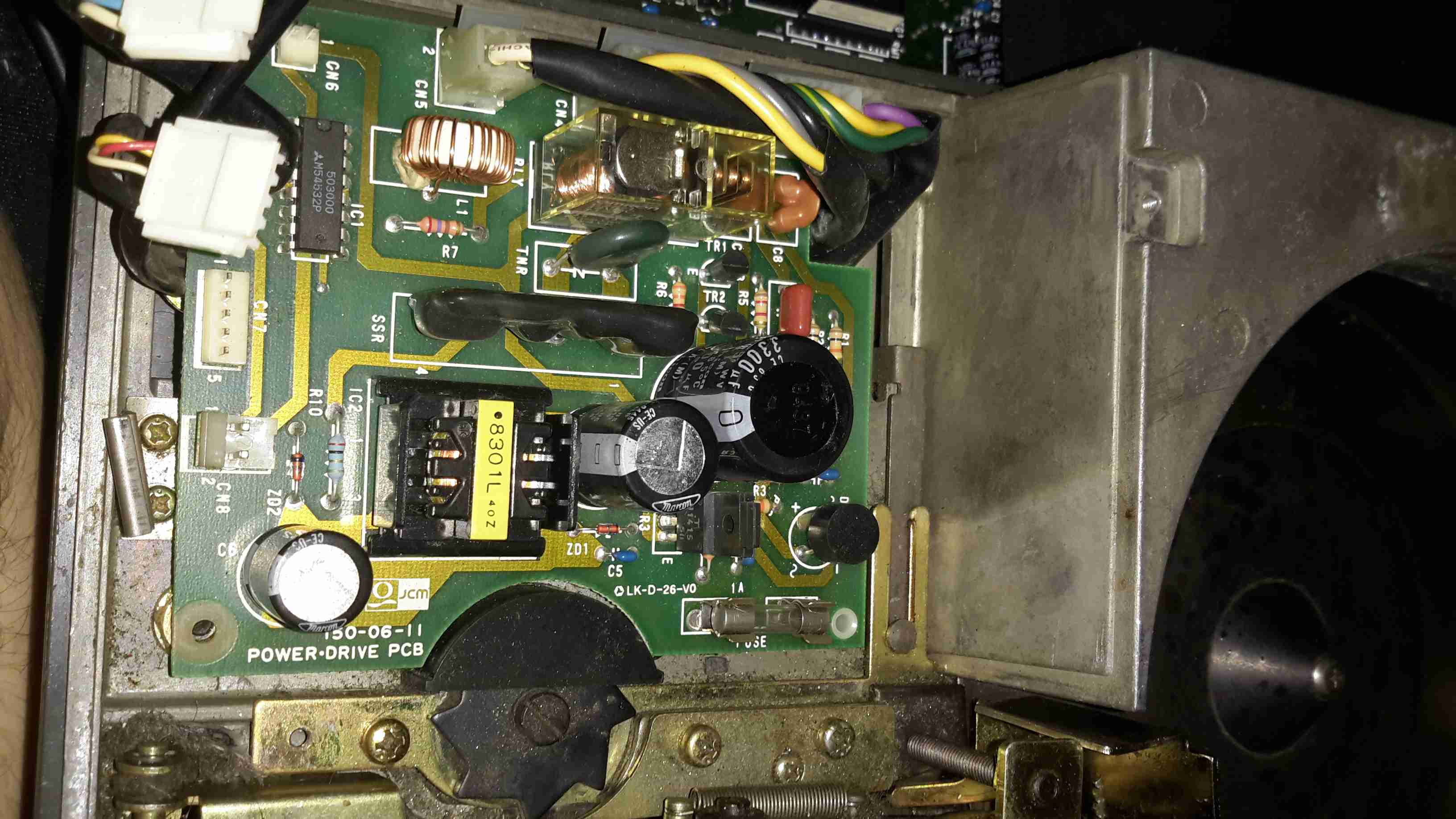
PSU & Switching
The counter is driven by a basic AC induction motor, the motor power relay & reversing relay is on this PCB, along with the 5v switching supply for the main CPU board.
The SMPS on this board looks like a standard mains unit, but it’s got one big difference. Under the frame next to the main motor is a relatively large transformer, with a 35v output. This AC is fed into the SMPS section of the PSU board to be converted to 5v DC for the logic.
I’m not sure why it’s been done this way, and have never seen anything similar before.
The edge of the coin channel can be seen here, the black star wheel rotates when a coin passes & registers the count.
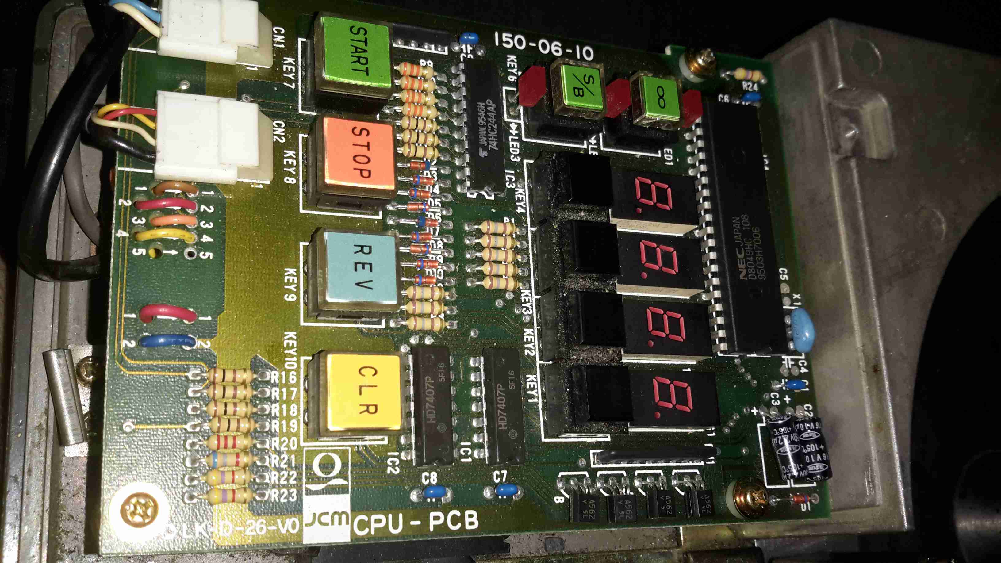
Controller PCB
Here’s the main controller PCB, IC date codes put the unit to about 1995. The main CPU is a NEC UPD8049HC 8-bit micro, no flash or EEPROM on this old CPU, simply mask ROM. Coin readout is done on the 4 7-segment LED displays. Not much to this counter, it’s both electronically & mechanically simple.
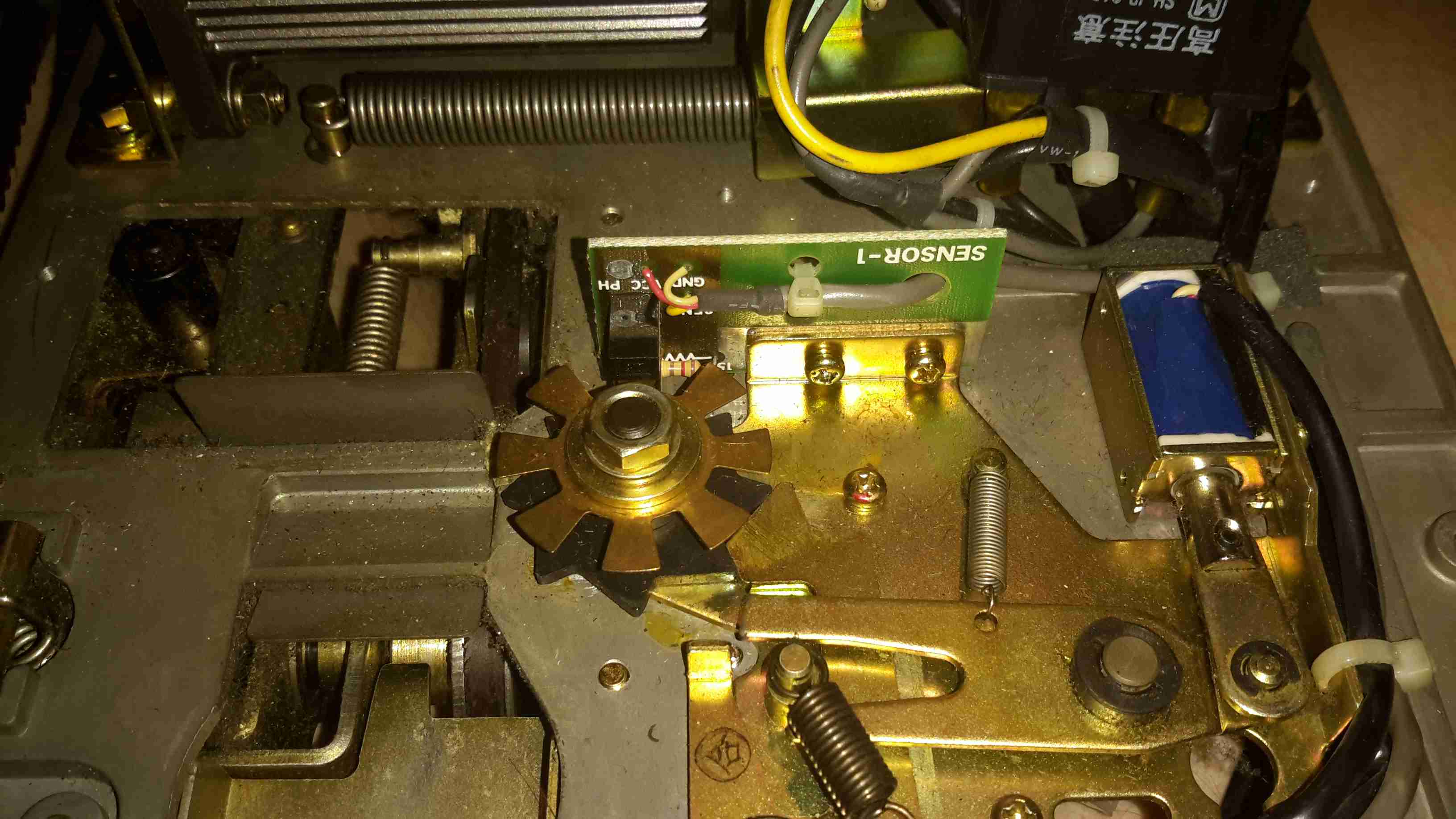
Counter Sensor
Coin counting is done by the star wheel mentioned above, which drives the interrupter disc on this photo-gate. The solenoid locks the counter shaft to prevent over or under counting when a set number of coins is to be counted.
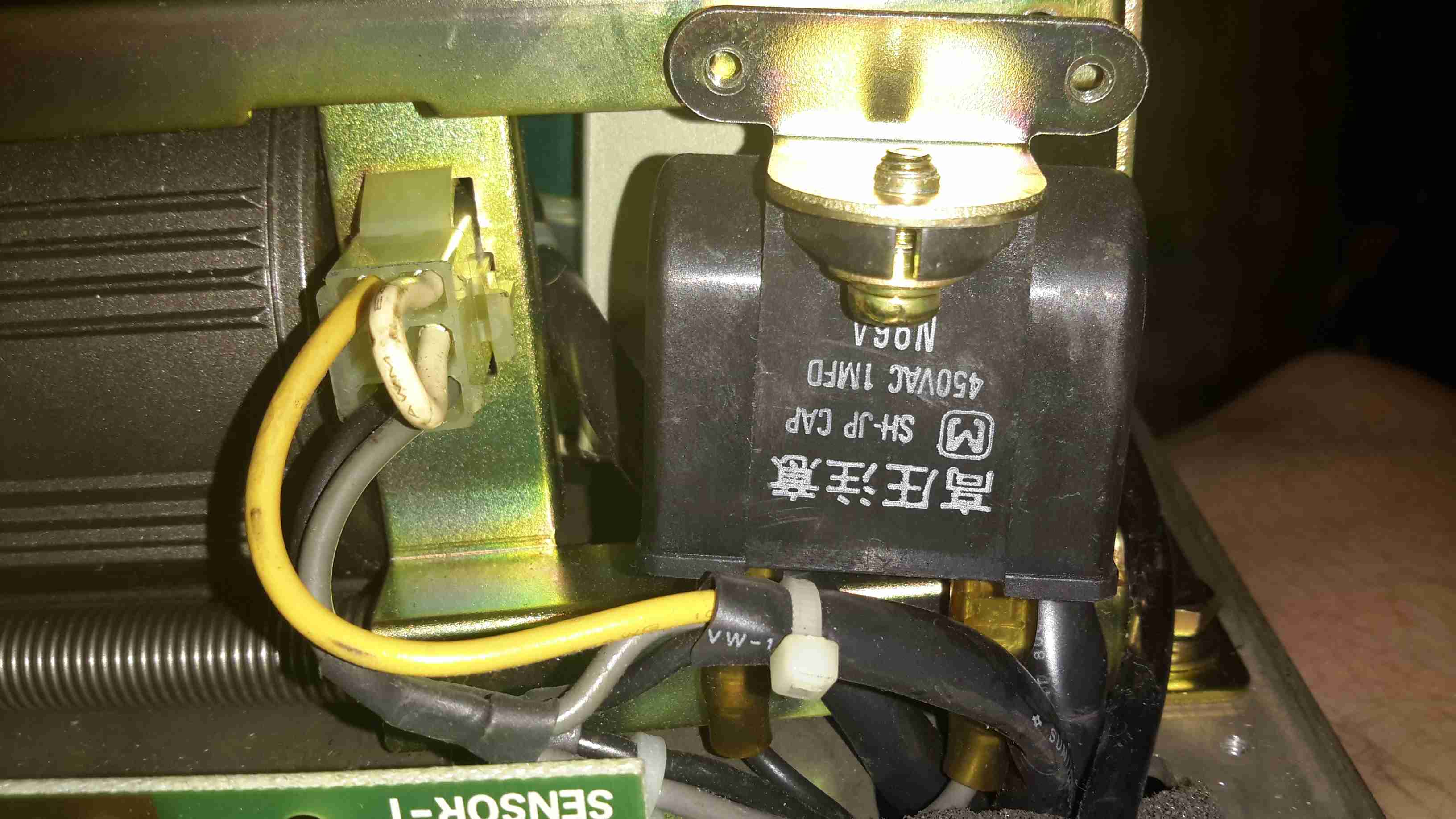
Motor Run Capacitor
Under the frame, here on the left is the small induction motor, only 6W, 4-pole. The run cap for the motor is in the centre, and the 35v transformer is just visible behind it.
Main Motor Drive
Main drive to the coin sorting mech is through rubber belts, and bevel gears drive the coin drum.
I’m still on my crusade of removing every trace of 240v mains power from my shack, so next up are my computer monitors.
I have 4 Dell monitors, of various models, hooked up to my main PC.
The monitor here is a Dell E207WFPc 20″ widescreen model. There will be more when I manage to get the others apart to do the conversion. However I’m hoping that the PSU boards are mostly the same.
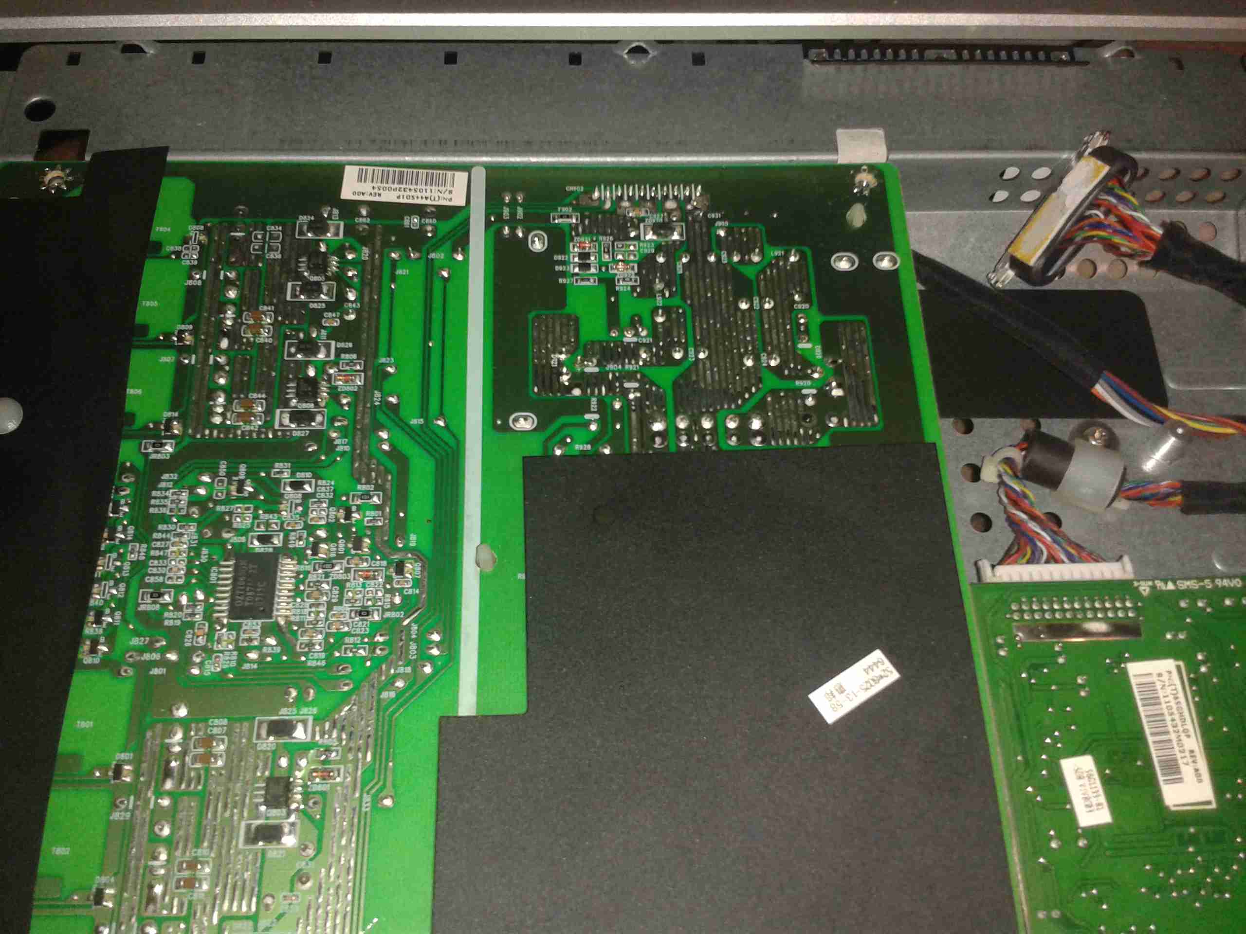
Panel Removed
There are no screws holding these monitors together, the front bezel is simply clicked into place in the back casing, these clips are the only thing that holds the relatively heavy glass LCD panel & it’s supporting frame! The image above shows the panel removed. The large board on the left is the power supply & backlight inverter, the smaller one on the right is the interface board to convert the DVI or VGA to LVDS for the LCD panel itself.
PSU Board
Here’s a closeup of the PSU board, the connector at centre right at the top of the PCB is the main power output, and also has a couple of signals to control the backlight inverter section of the PSU, on the left side. The PSU requirements for this monitor are relatively simple, at 14.5v for the backlight & 5v for the logic board.
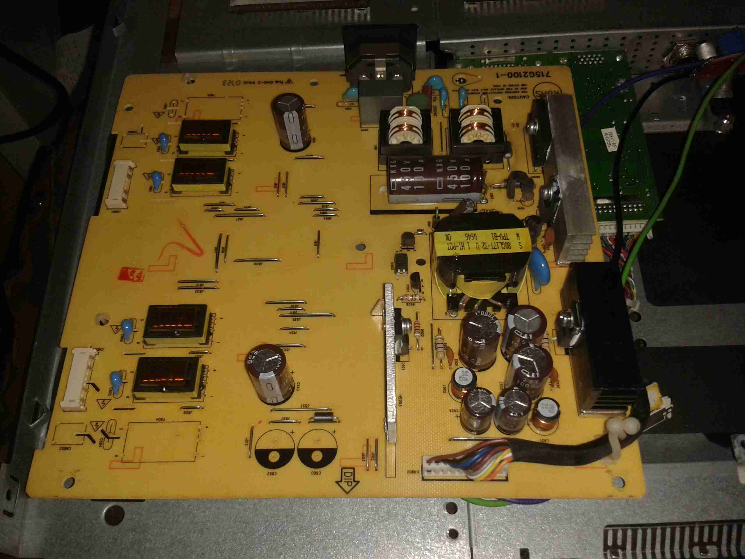
PSU
Here’s the top of the PSU board, very simple with the mains supply on the right side, and the backlight inverter transformers on the left.
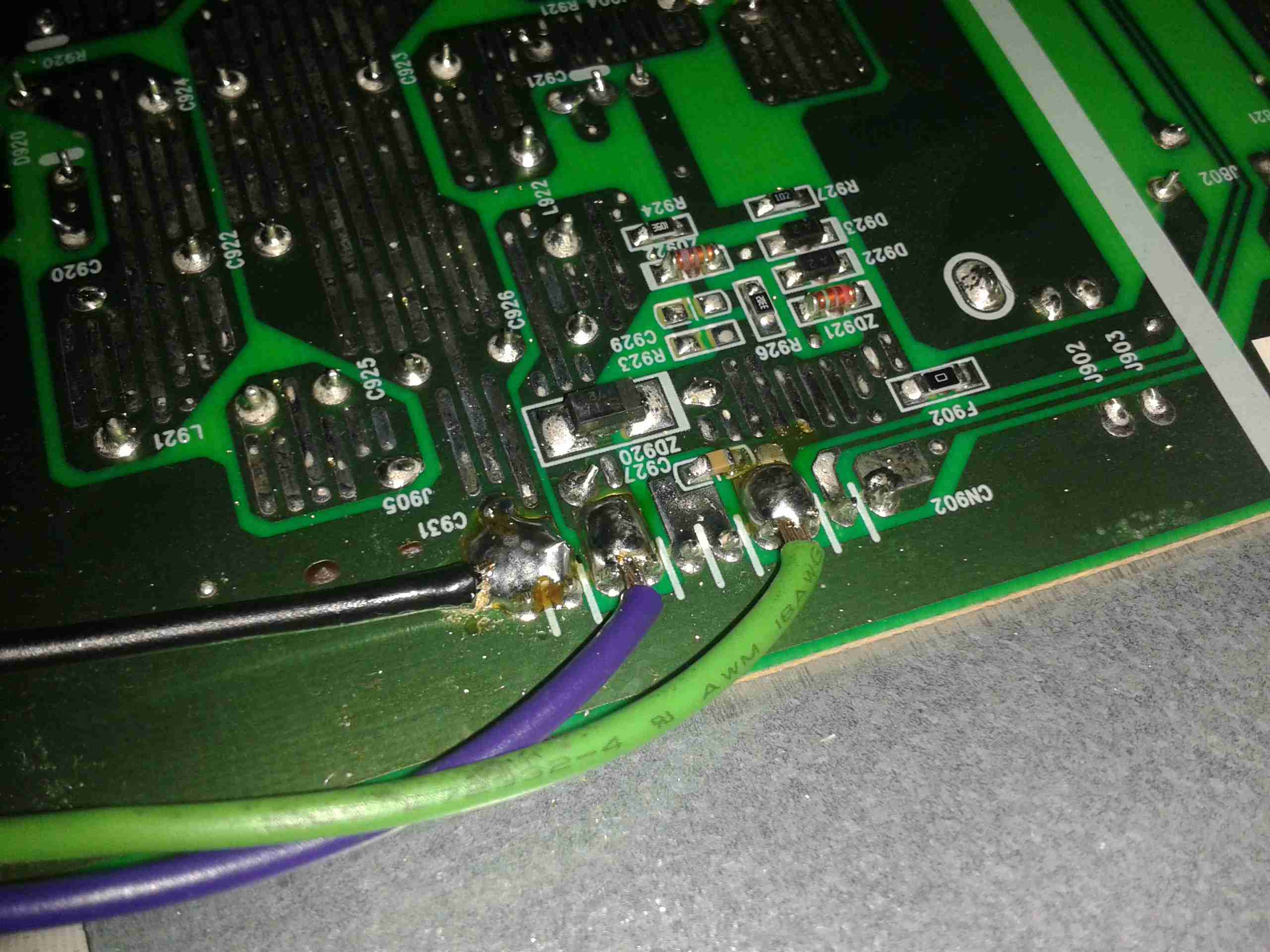
Hooked In
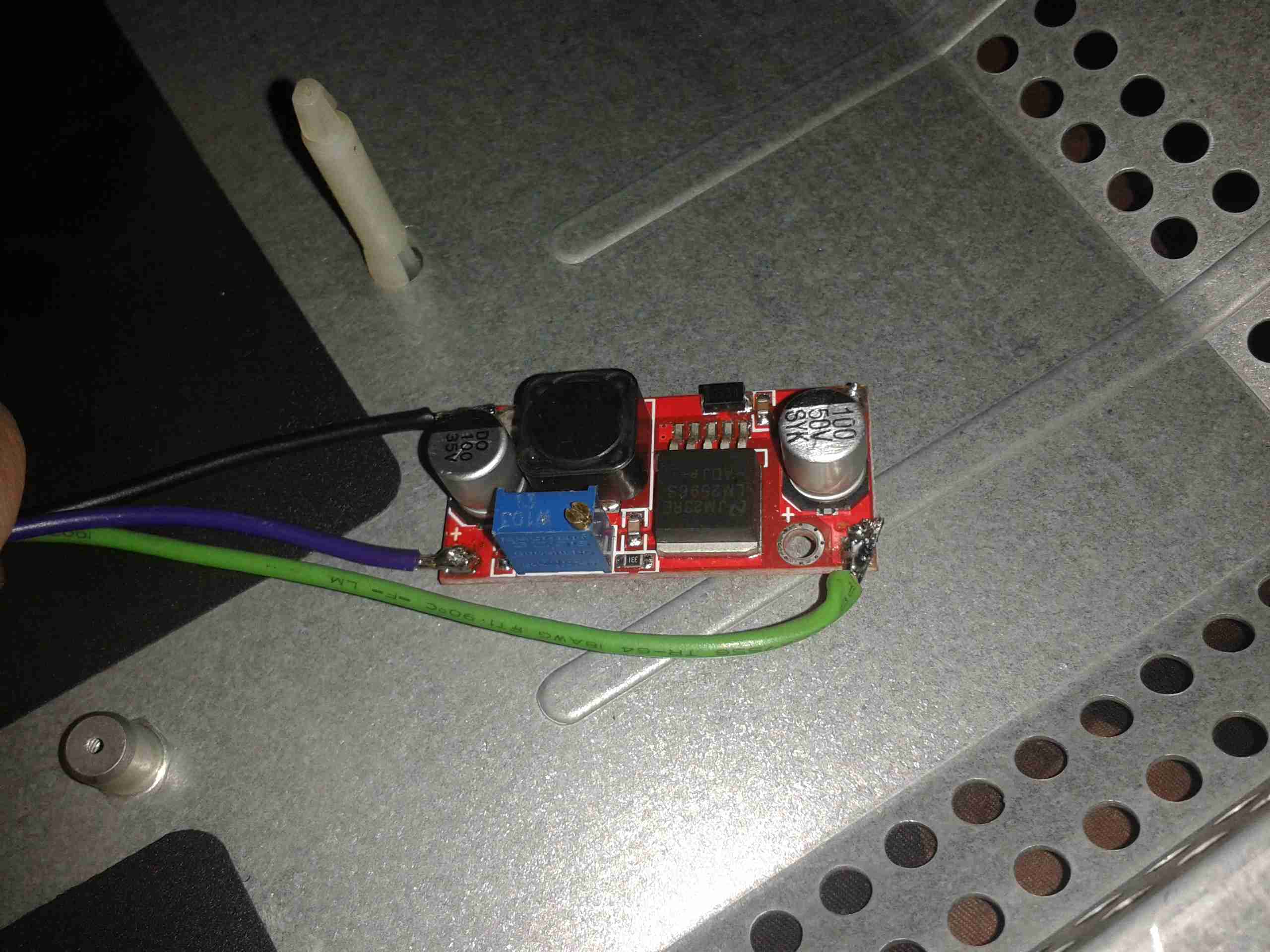
Here I’ve hooked into the power rails on the supply, to attach my own 12v regulators. The green wire is +14.5v, and the purple is +5v. Black is common ground.
5v Regulator
On doing some testing, the backlight inverter section doesn’t seem to mind voltages between 11.5-14.5v, so a separate regulator isn’t required there. Even running off batteries that’s within the range of both charging & discharging. The only regulator required is a 5v one to reduce the input voltage for the logic PCB.
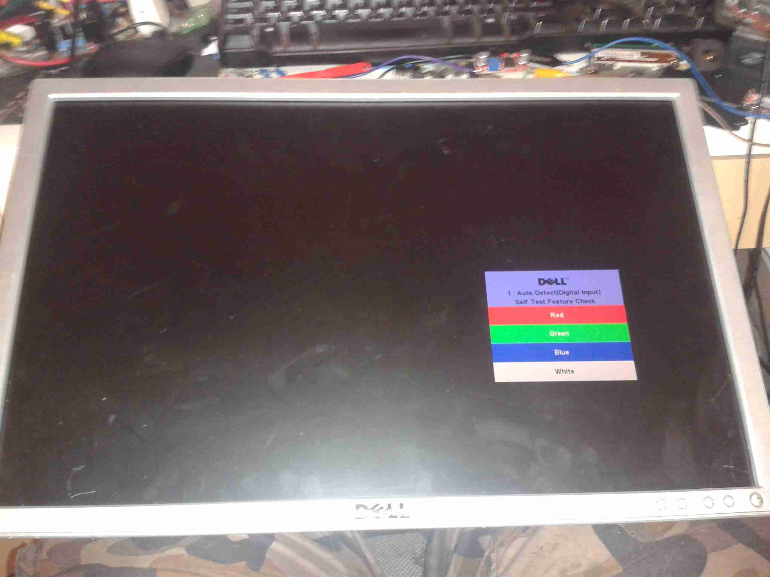
First Test
On applying some 12v power to the regulator input, we have light! Current draw at 12.5v is 2.65A for a power consumption of 33W.
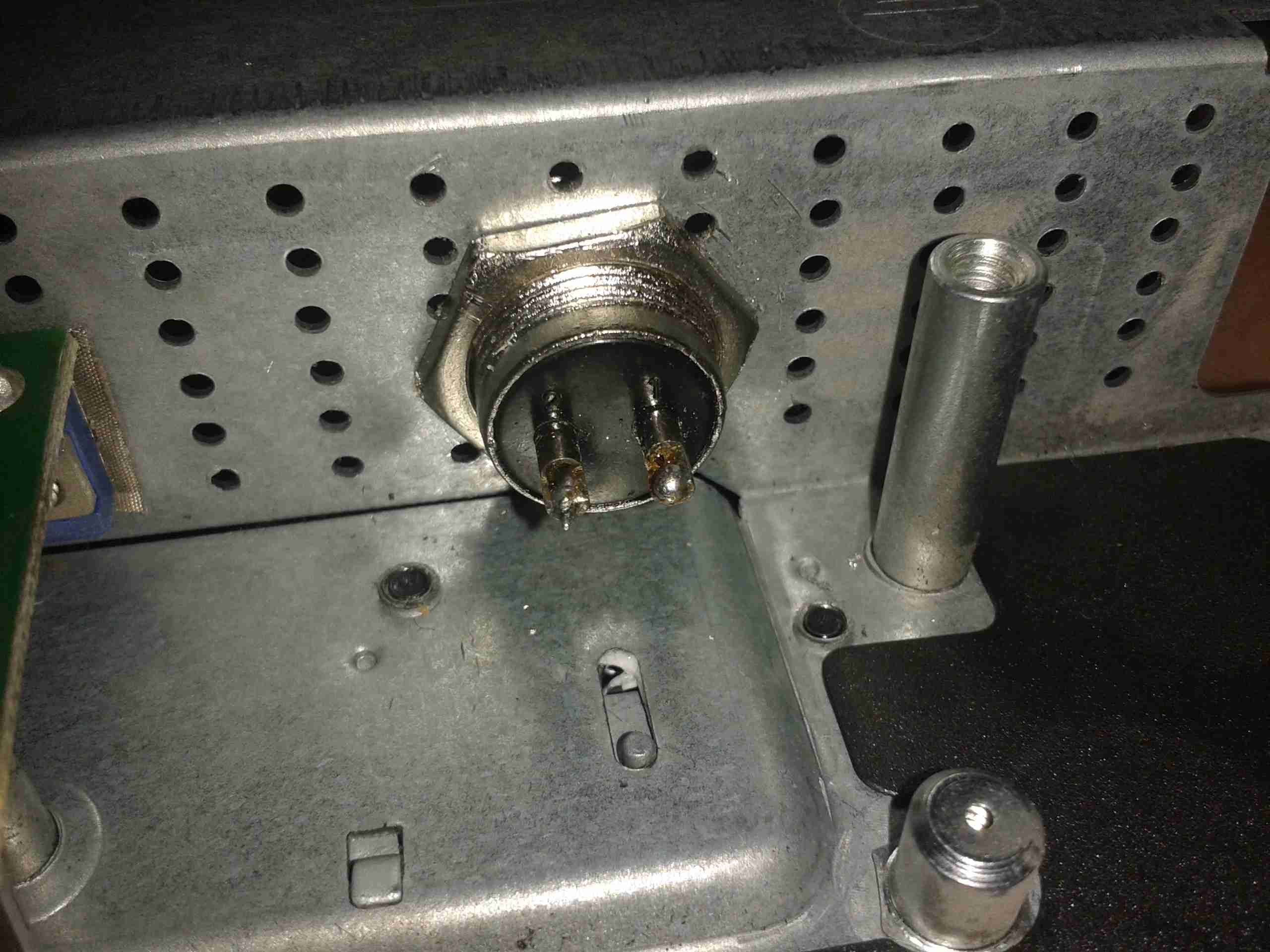
12v Input
There’s plenty of room in the back casing to mount a 12v input socket, I have left the mains supply intact so it can be used on dual supply.
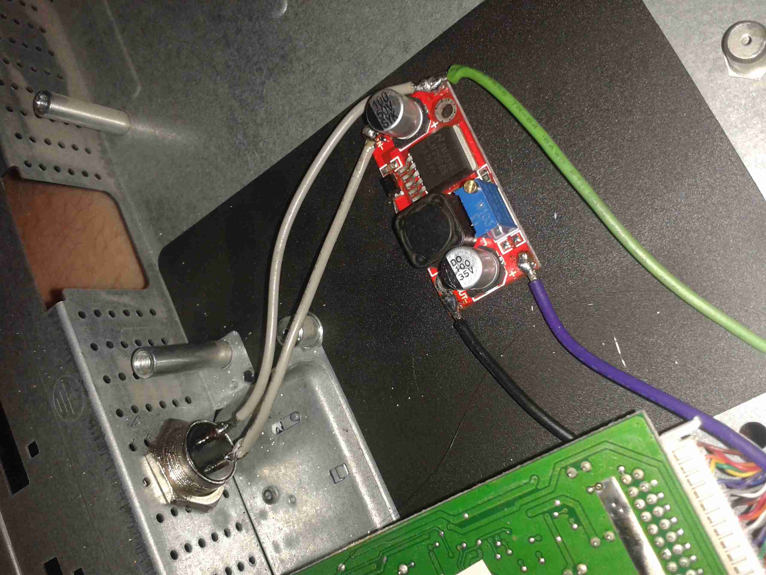
Final Wiring
Here’s the 5v regulator mounted on the back of the casing, all wired up & ready to go.
A while ago I blogged about modifying the output voltage of some surplus Cisco switch power supplies to operate at 13.8v.
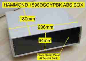
Since I was able to score a nice Hammond 1598DSGYPBK ABS project box on eBay, I’ve built one of the supplies into a nice bench unit.
Hammond ABS CaseSupply Unit
Above is the supply mounted into the box, I had to slightly trim one edge of the PCB to make everything fit, as it was just a couple of mm too wide. Luckily on the mains side of the board is some space without any copper tracks.
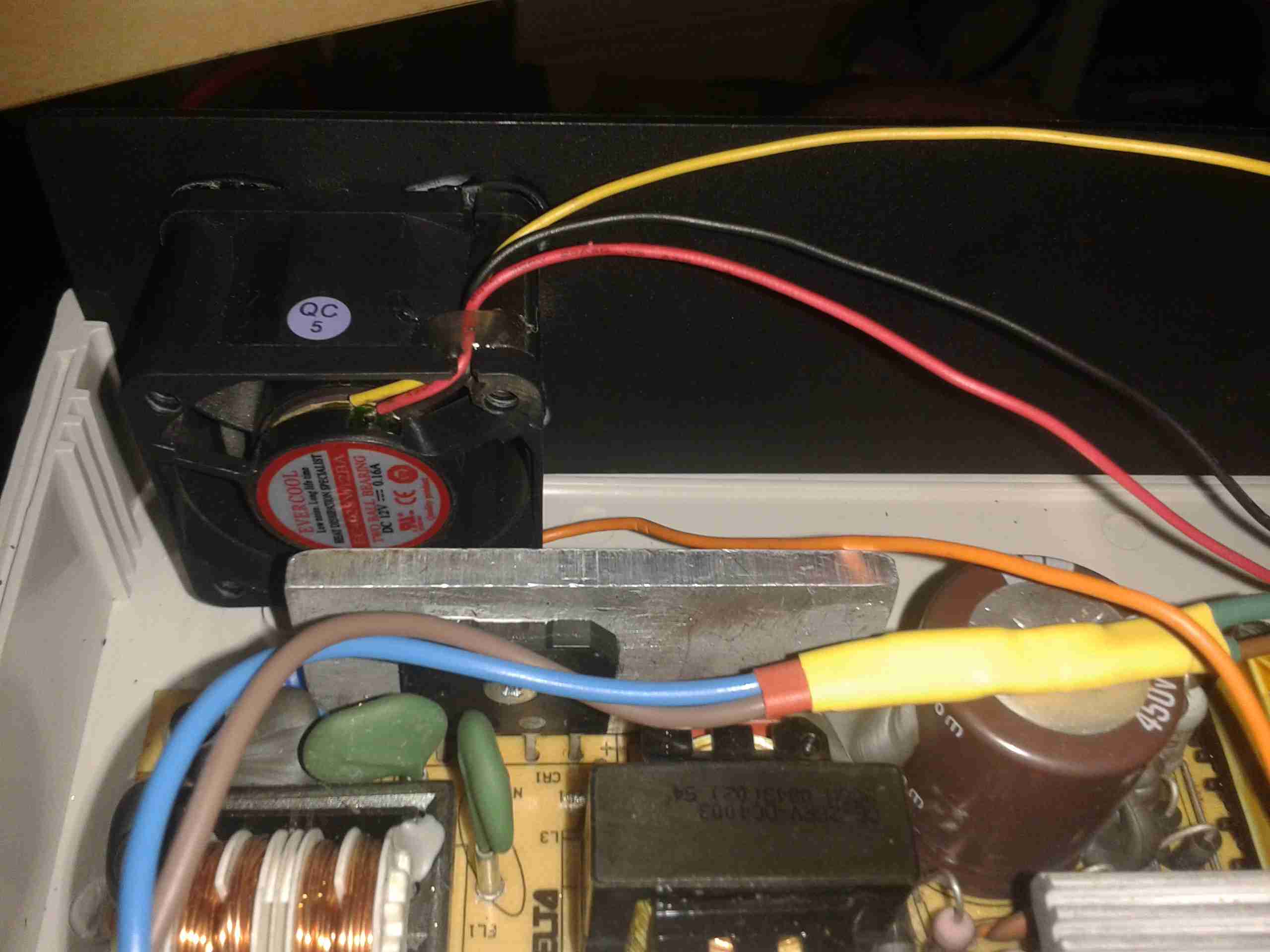
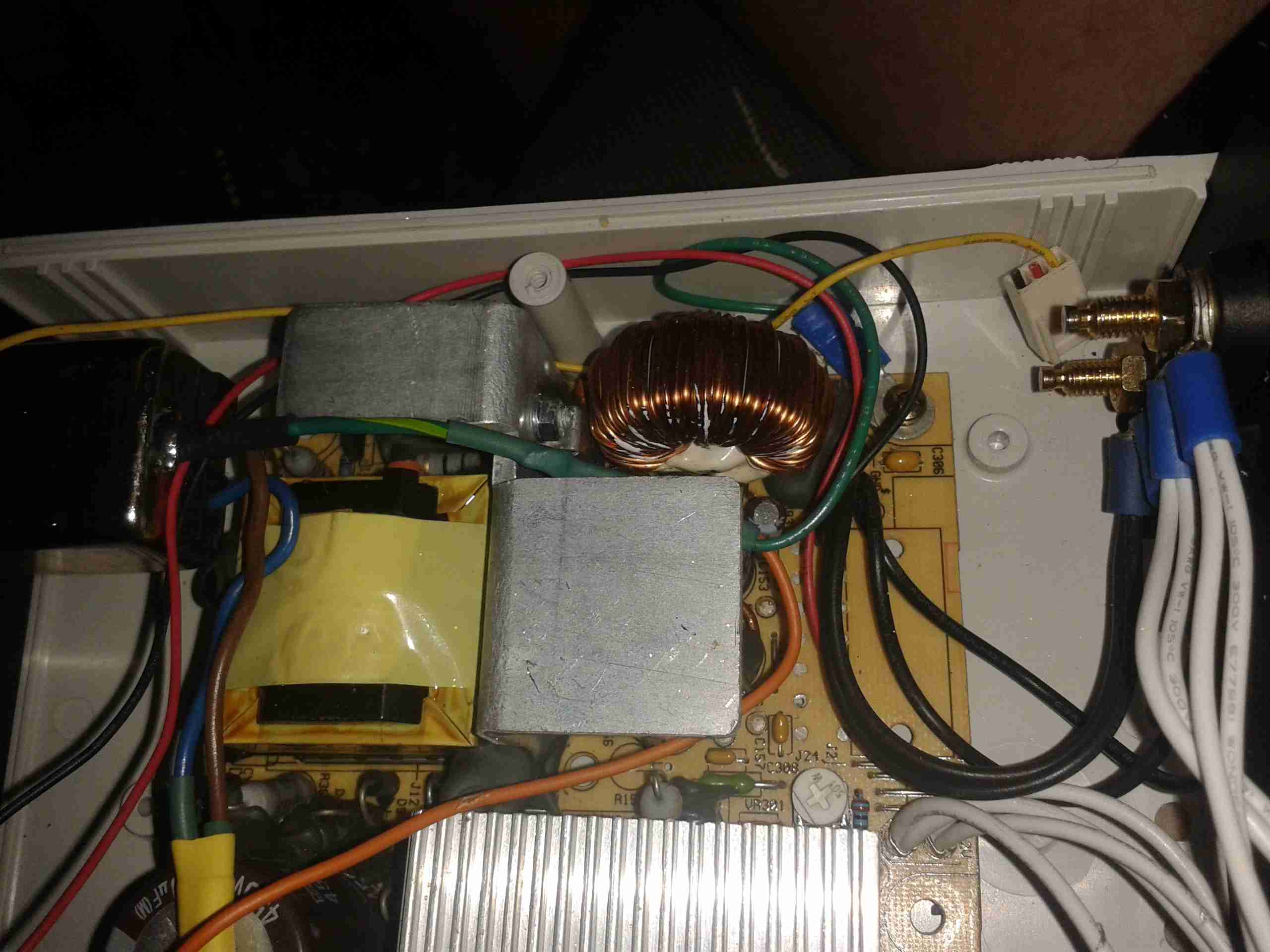
PSU Fan
These supplies are very high quality & very efficient, however they came from equipment that was force-air cooled. Running the PSU in this box with no cooling resulted in overheating. Because of this I have added a small 12v fan to move some air through the case. The unit runs much cooler now. To allow the air to flow straight through the case, I drilled a row of holes under the front edge as vents.
Output Side
Here is the output side of the supply, it uses standard banana jacks for the terminals. I have used crimp terminals here, but they are soldered on instead of crimped to allow for higher current draw. The negative return side of the output is mains earth referenced.
I have tried to measure output ripple on this supply, but with my 10X scope probe, and the scope set to 5mV/Div, the trace barely moves. The output is a very nice & stable DC.
This supply is now running my main radio in the shack, and is small enough to be easily portable when I move my station.
This is a late 90’s business timeclock, used for maintaining records of staff working times, by printing the time when used on a sheet of card.
Front Internal
Here is the top cover removed, which is normally locked in place to stop tampering. The unit is programmed with the 3 buttons & the row of DIP switches along the top edge.
Instructions
Closeup of the settings panel, with all the various DIP switch options.
CPU & Display
Cover plate removed from the top, showing the LCD & CPU board, the backup battery normally fits behind this. The CPU is a 4-bit microcontroller from NEC, with built in LCD driver.
PSU & Drivers
Power Supply & prinhead drivers. This board is fitted with several NPN Darlington transistor arrays for driving the dox matrix printhead.
Printhead
Printhead assembly itself. The print ribbon fits over the top of the head & over the pins at the bottom. The drive hammers & solenoids are housed in the circular top of the unit.
Printhead Bottom
Bottom of the print head showing the row of impact pins used to create the printout.
Bottom of the solenoid assembly with the ribbon cable for power. There are 9 solenoids, to operate the 9 pins in the head.
Return Spring
Top layer of the printhead assembly, showing the leaf spring used to hold the hammers in the correct positions.
Hammers
Hammer assembly. The fingers on the ends of the arms push on the pins to strike through the ribbon onto the card.
Solenoids
The ring of solenoids at the centre of the assembly. These are driven with 3A darlington power arrays on the PSU board.
Gearbox Internals
There is only a single drive motor in the entire unit, that both clamps the card for printing & moves the printhead laterally across the card. Through a rack & pinion this also advances the ribbon with each print.
Tip Jar
If you’ve found my content useful, please consider leaving a donation by clicking the Tip Jar below!
All collected funds go towards new content & the costs of keeping the server online.