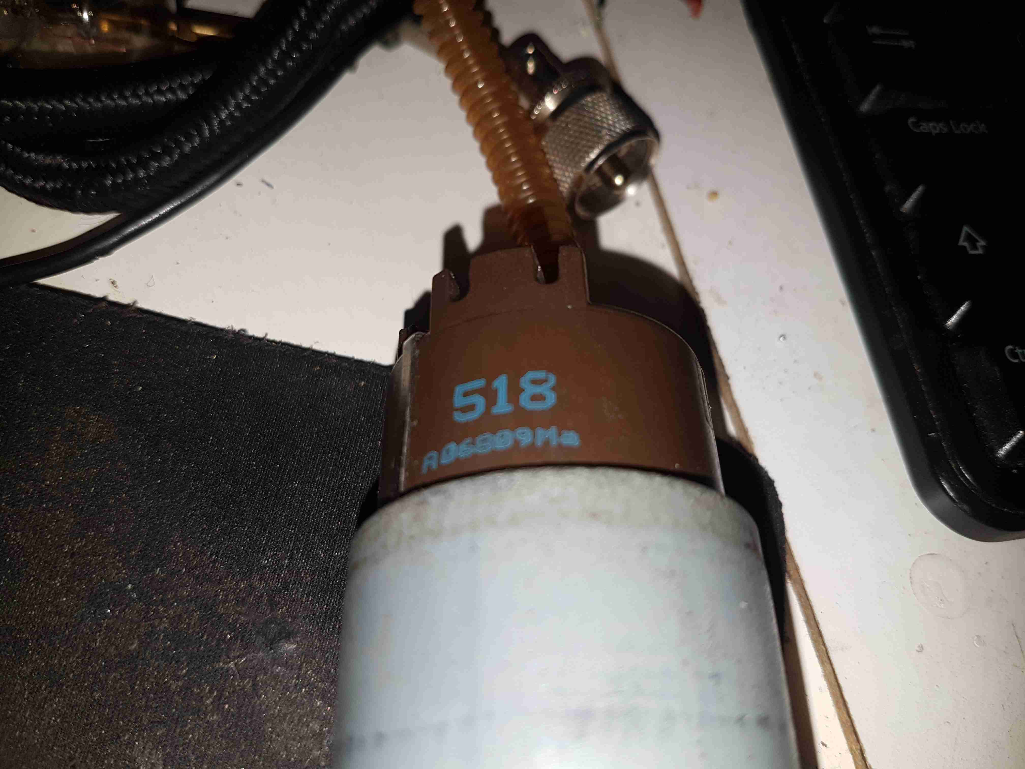
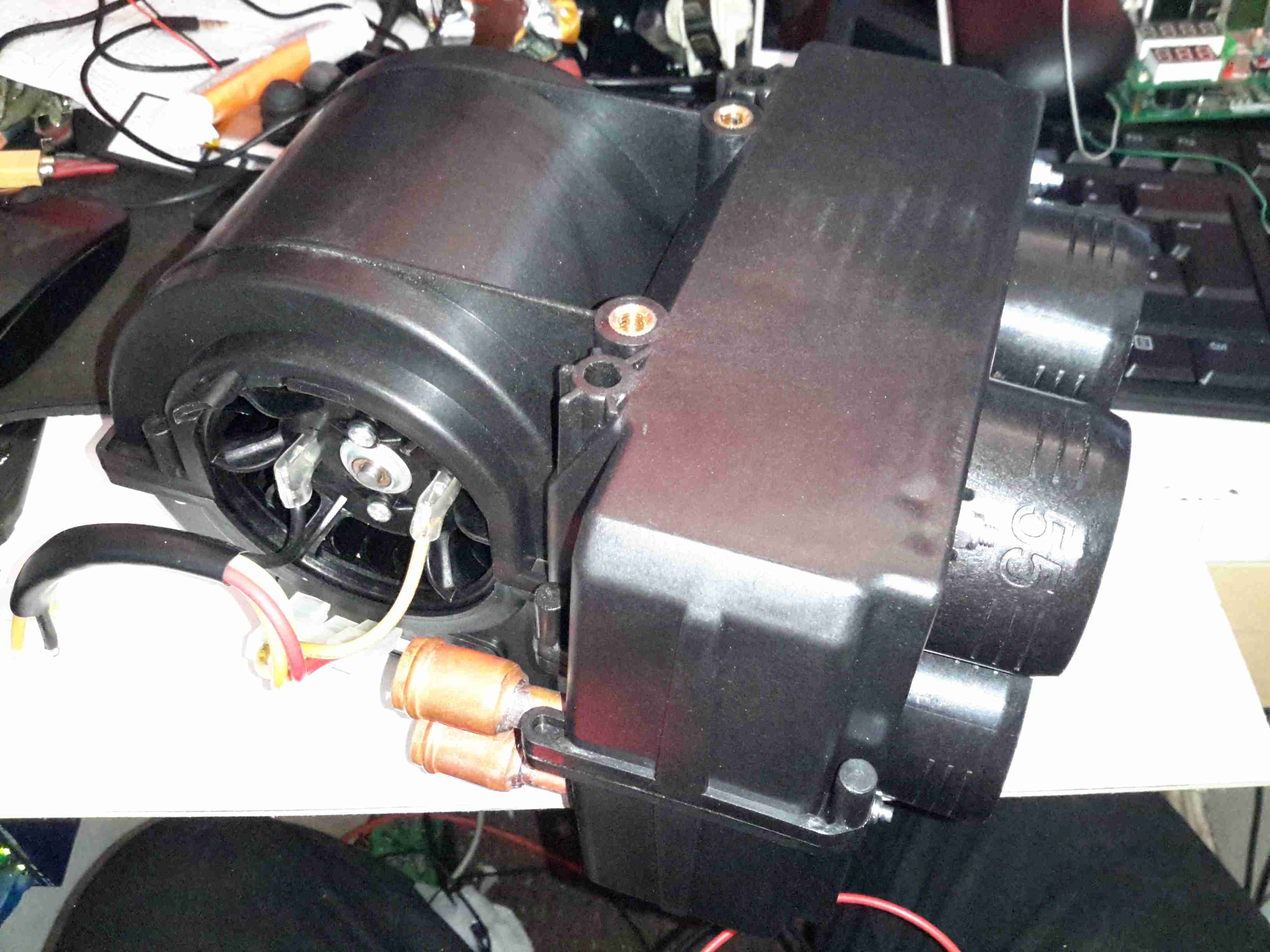
Here’s a destructive teardown of an automotive in-tank turbine fuel pump, used on modern Petrol cars. These units sit in the tank fully immersed in the fuel, which also circulates through the motor inside for cooling. These pumps aren’t serviceable – they’re crimped shut on both ends. Luckily the steel shell is thin, so attacking the crimp joint with a pair of mole grips & a screwdriver allowed me inside.
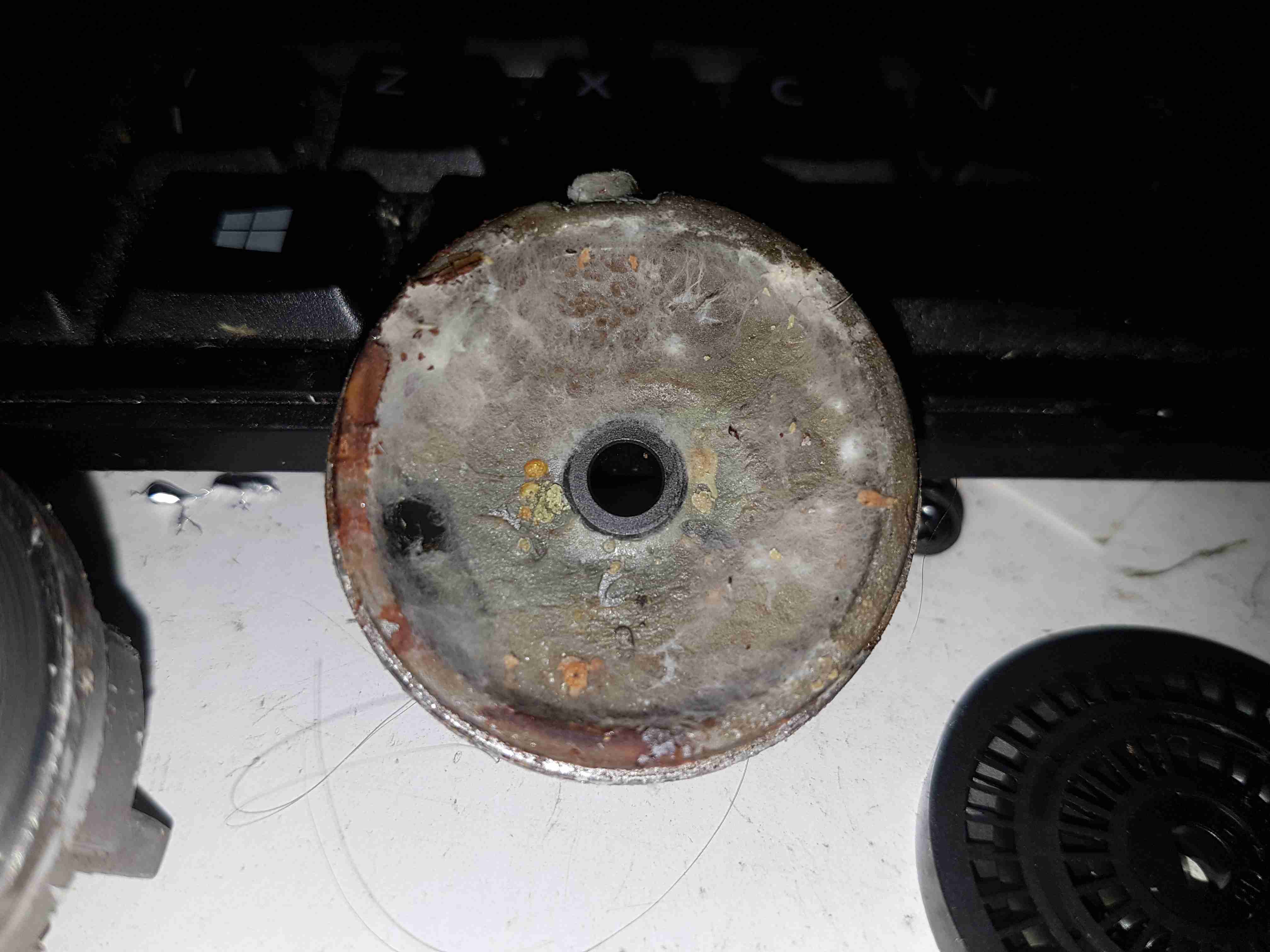
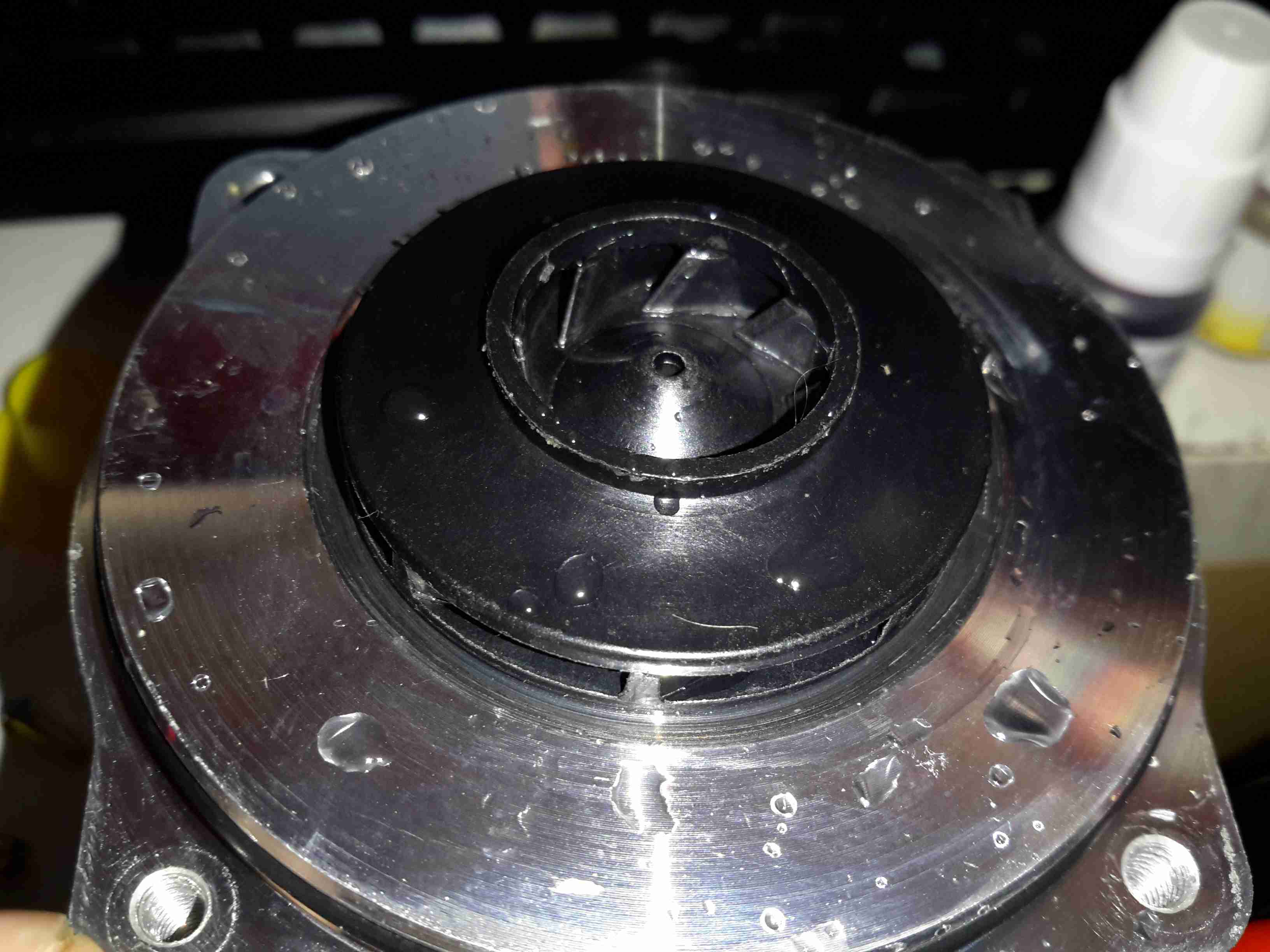
End Bell
The input endbell of the pump has the fuel inlet ports, the channels are visible machined into the casting. There’s a pair of channels for two pump outputs – the main fuel rail to the engine, and an auxiliary fuel output to power a venturi pump. The fuel pump unit sits inside a swirl pot, which holds about a pint of fuel. These are used to ensure the pump doesn’t run dry & starve the engine when the tank level is low & the car is being driven hard. The venturi pump draws fuel from the main tank into the swirl pot. A steel ball is pressed in to the end bell to provide a thrust bearing for the motor armature.
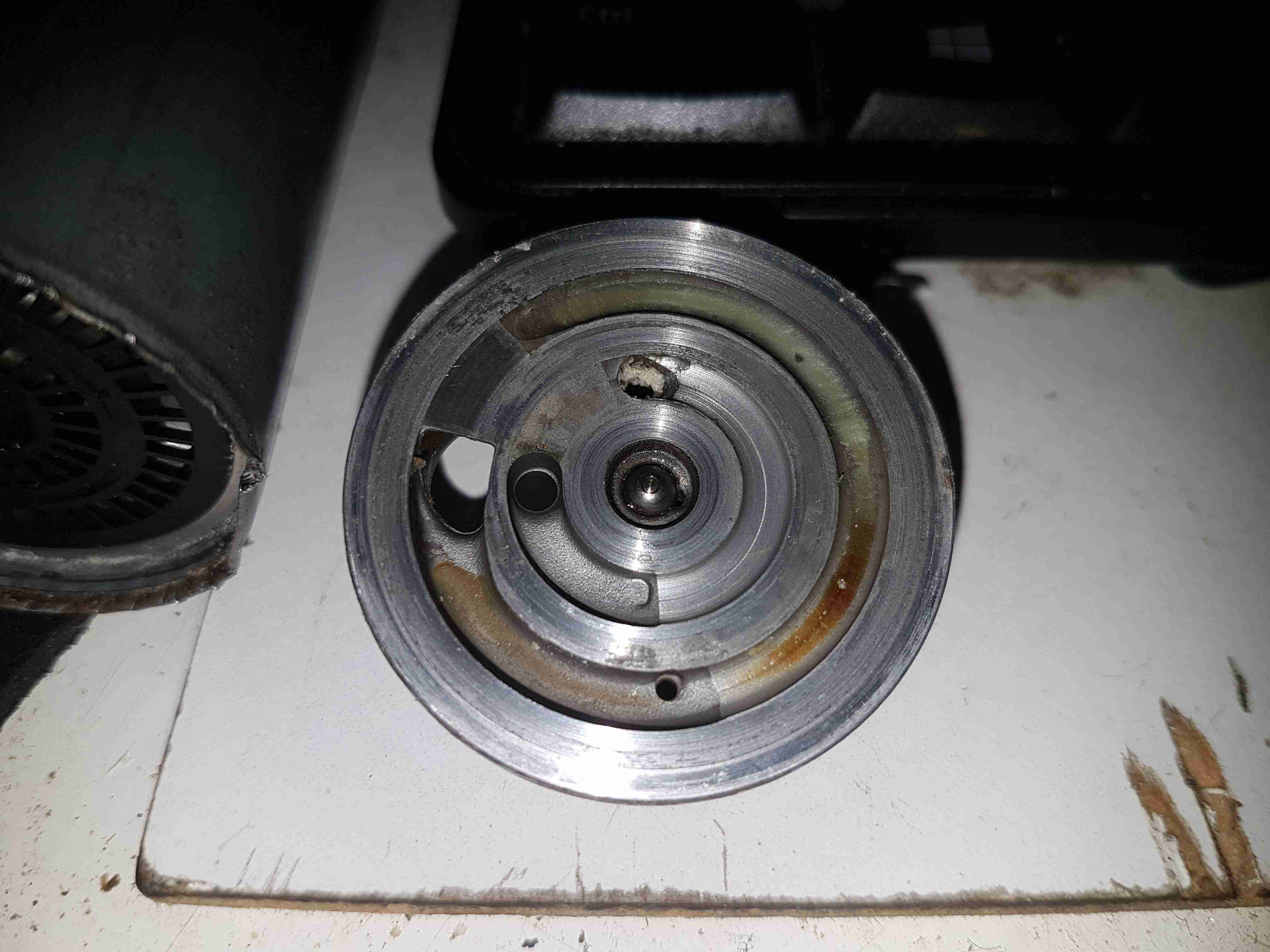
Turbine Impeller
The core of the pump is this impeller, which is similar to a side-channel blower. From what I’ve been able to find these units supply pressures up to about 70PSI for the injector rail. The outside ring is the main fuel pump, while the smaller inner one provides the pressure to run the venturi pump.
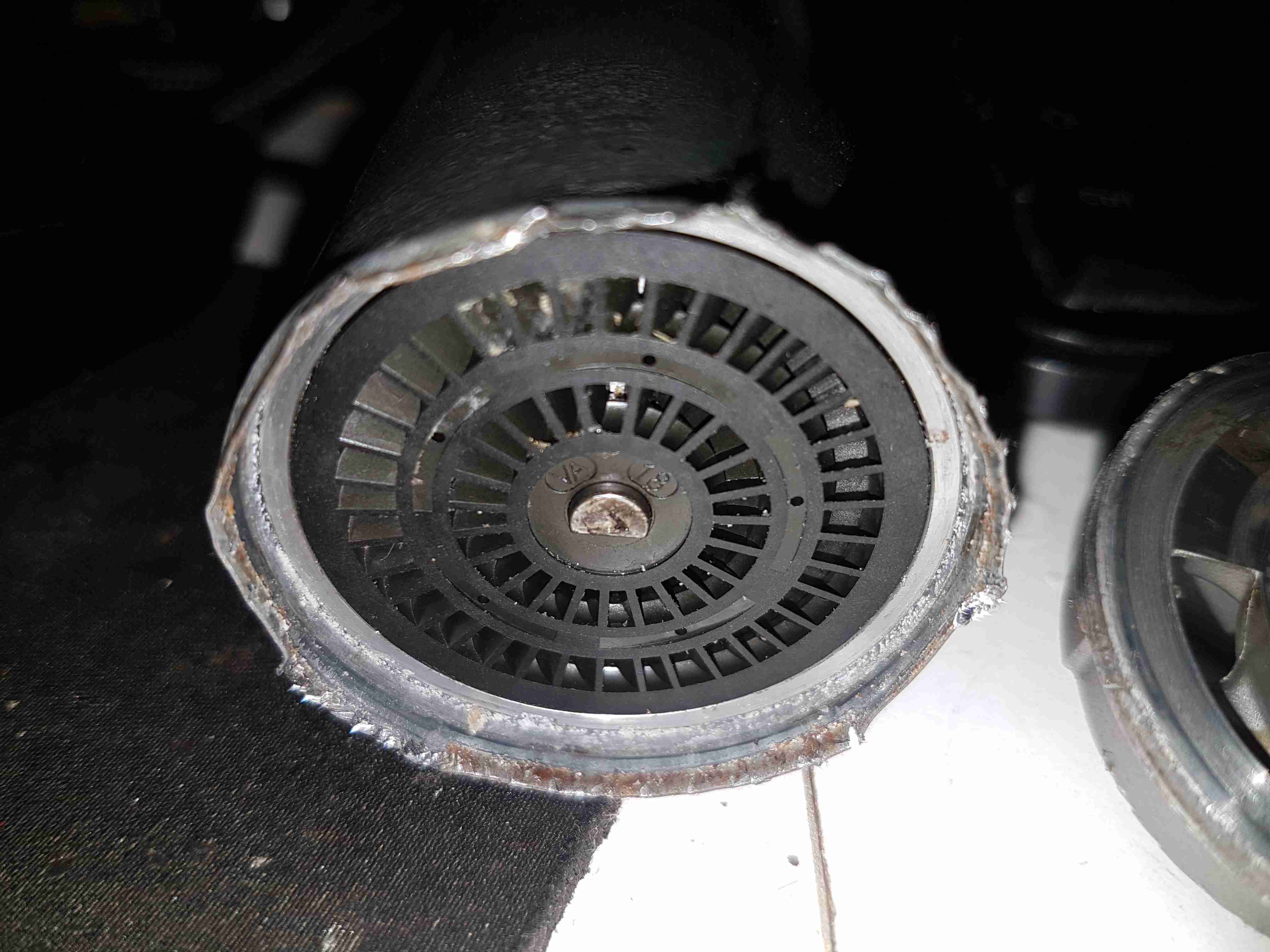
Pump Housing
The other side of the machined pump housing has the main output channel, with the fuel outlet port at the bottom. The motor shaft is supported in what looks like a carbon bearing.
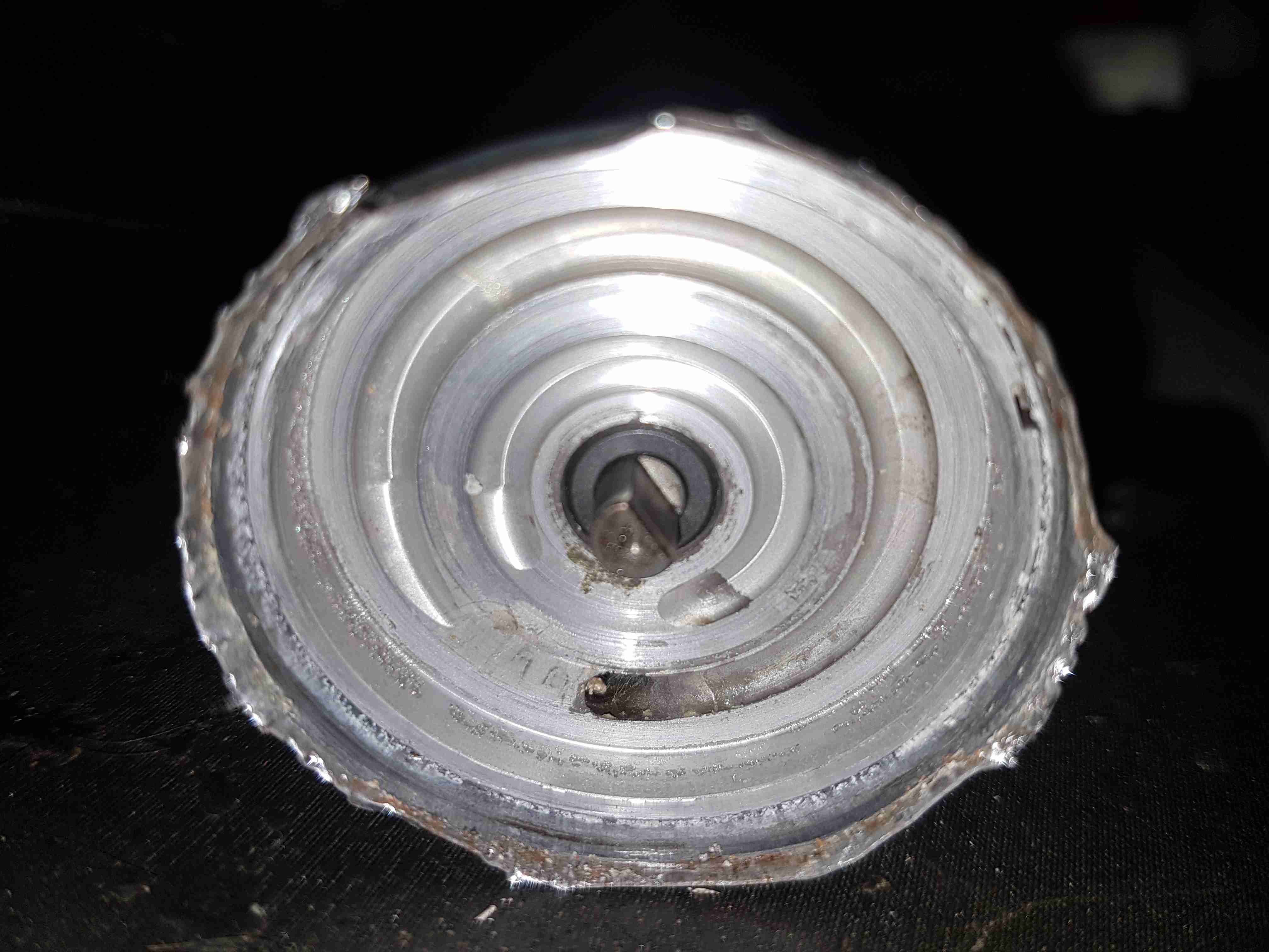
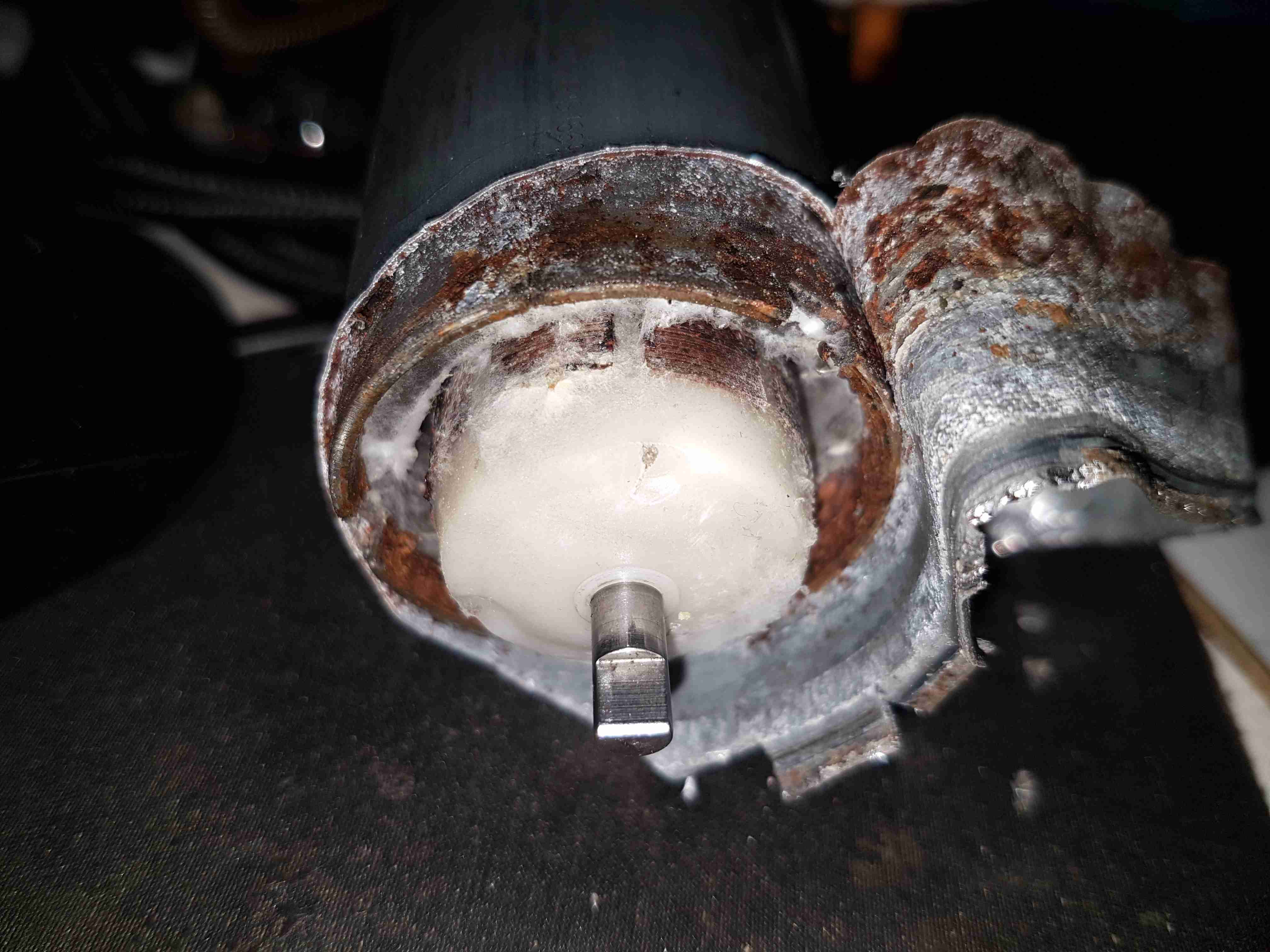
Midsection
Removing the pump intermediate section with the bearing reveals quite a bit of fungus – it’s probably been happy sat in here digesting what remains of the fuel.
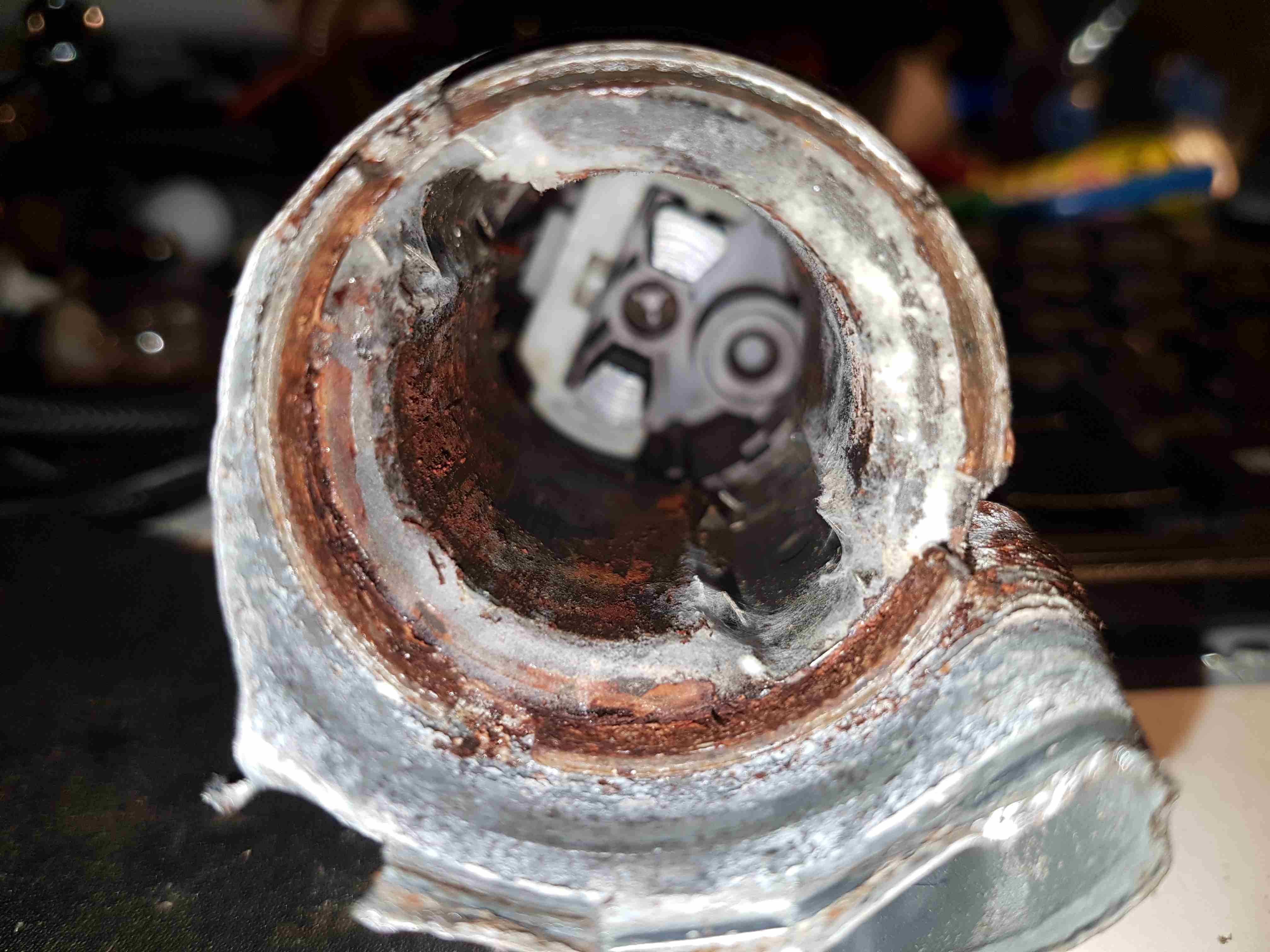
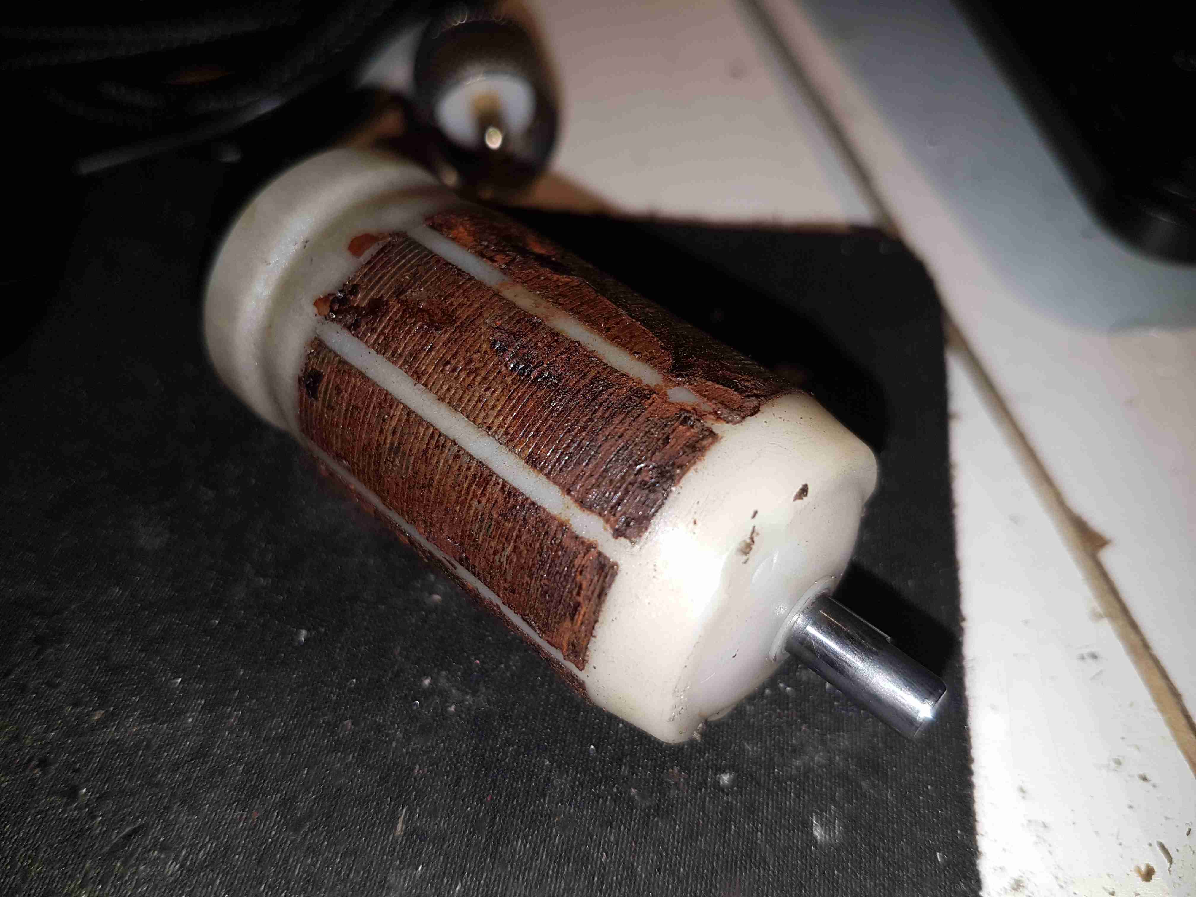
Armature Exposed
Some peeling with mole grips allows the motor to come apart entirely. The drive end of the armature is visible here.
Motor Can
The outer shell of the motor holds yet more fungus, along with some rust & the pair of ceramic permanent magnets.
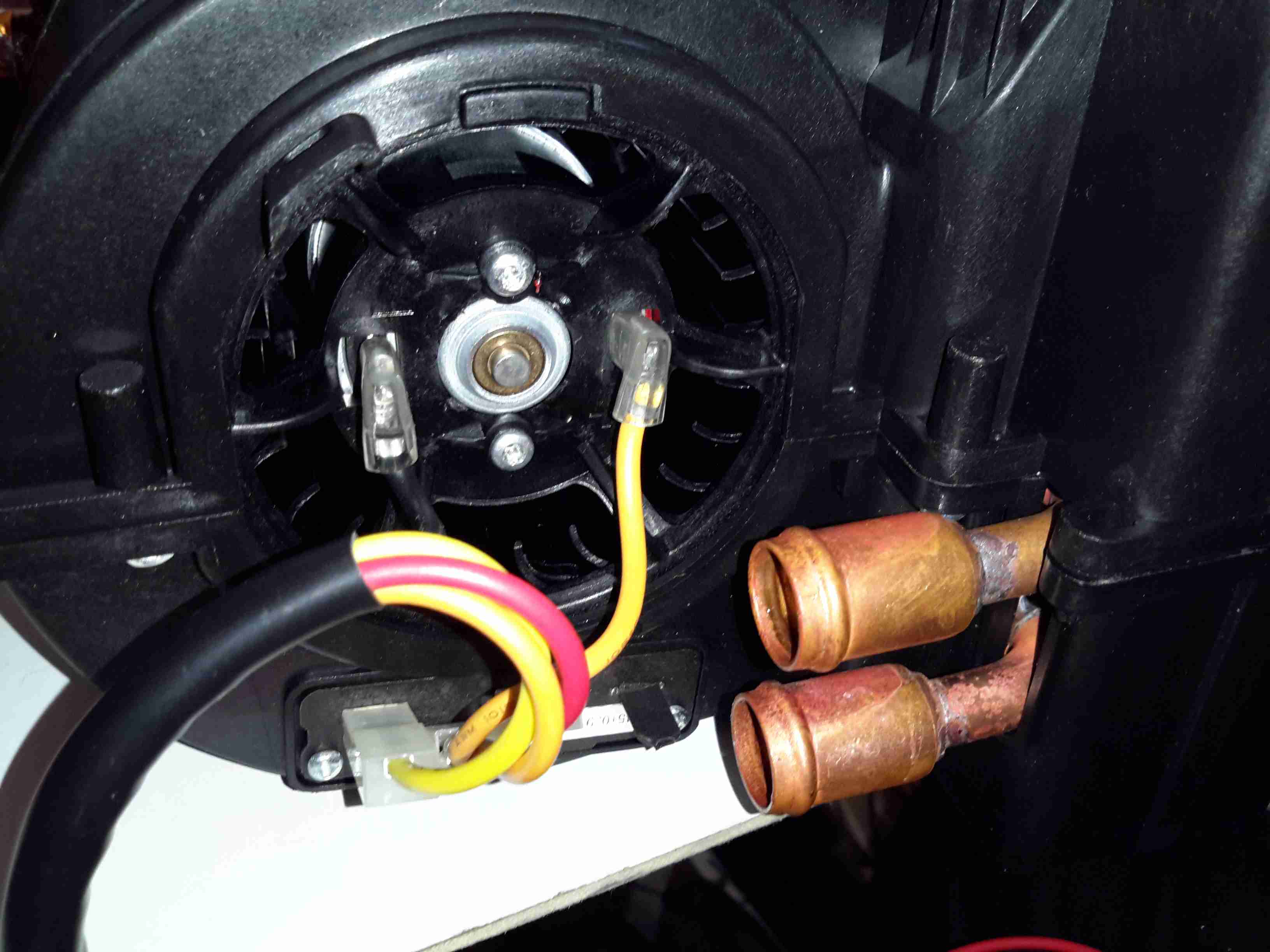
Brushes
The other end of the pump has the brush assembly, and the fuel outlet check valve to the right. The bearing at this end is just the plastic end cap, since there are much lower forces at this end of the motor. The fuel itself provides the lubrication required.
Potted Armature
With the armature pulled out of the housing, it’s clear that there’s been quite a bit of water in here as well, with the laminations rusting away. This armature is fully potted in plastic, with none of the copper windings visible.
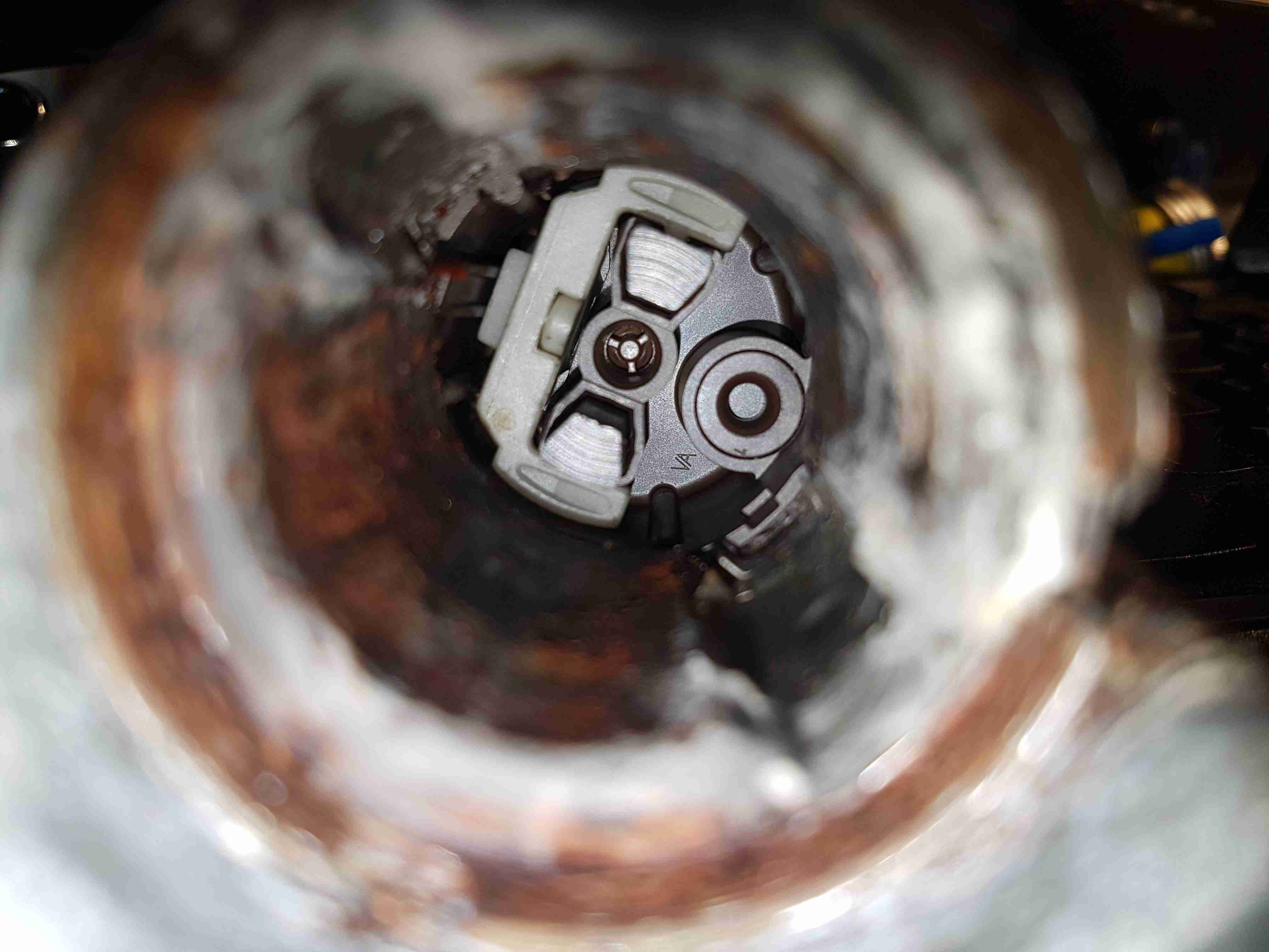
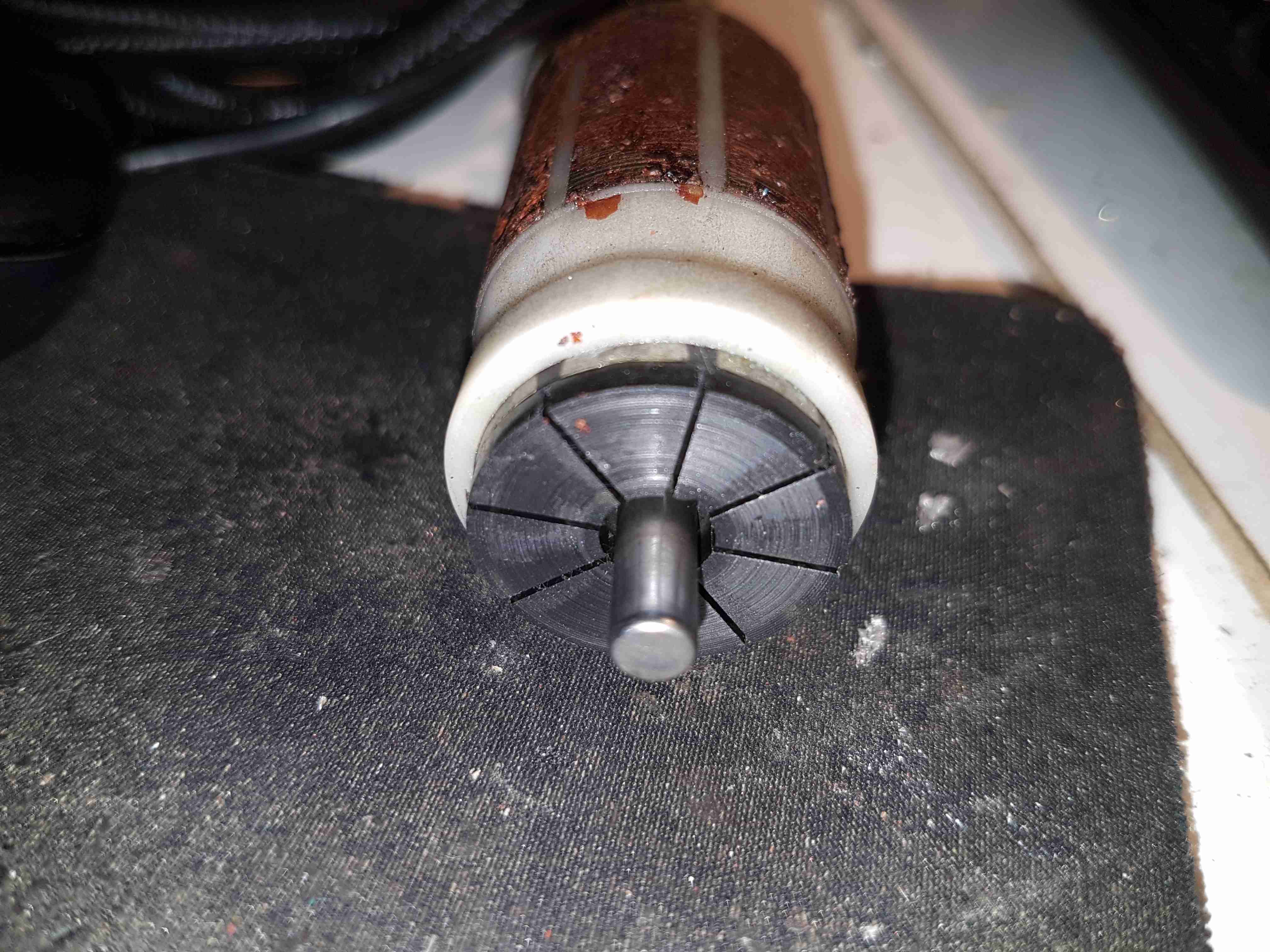
Carbon Commutator
The commutator in these motors is definitely a strange one – it’s axial rather than radial in construction, and the segments are made of carbon like the brushes. No doubt this is to stop the sparking that usually occurs with brushed motors – preventing ignition of fuel vapour in the pump when air manages to get in as well, such as in an empty tank.
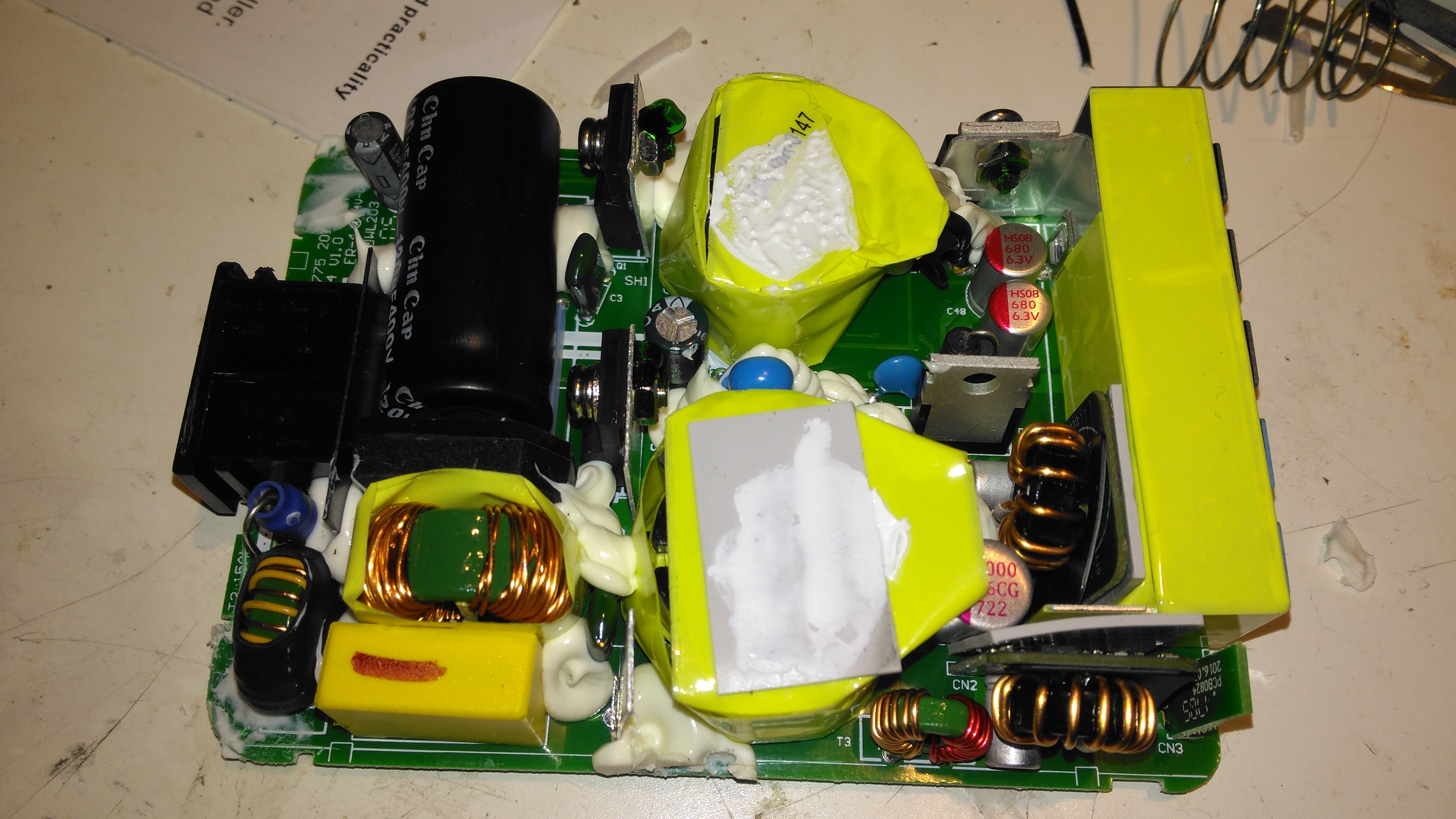
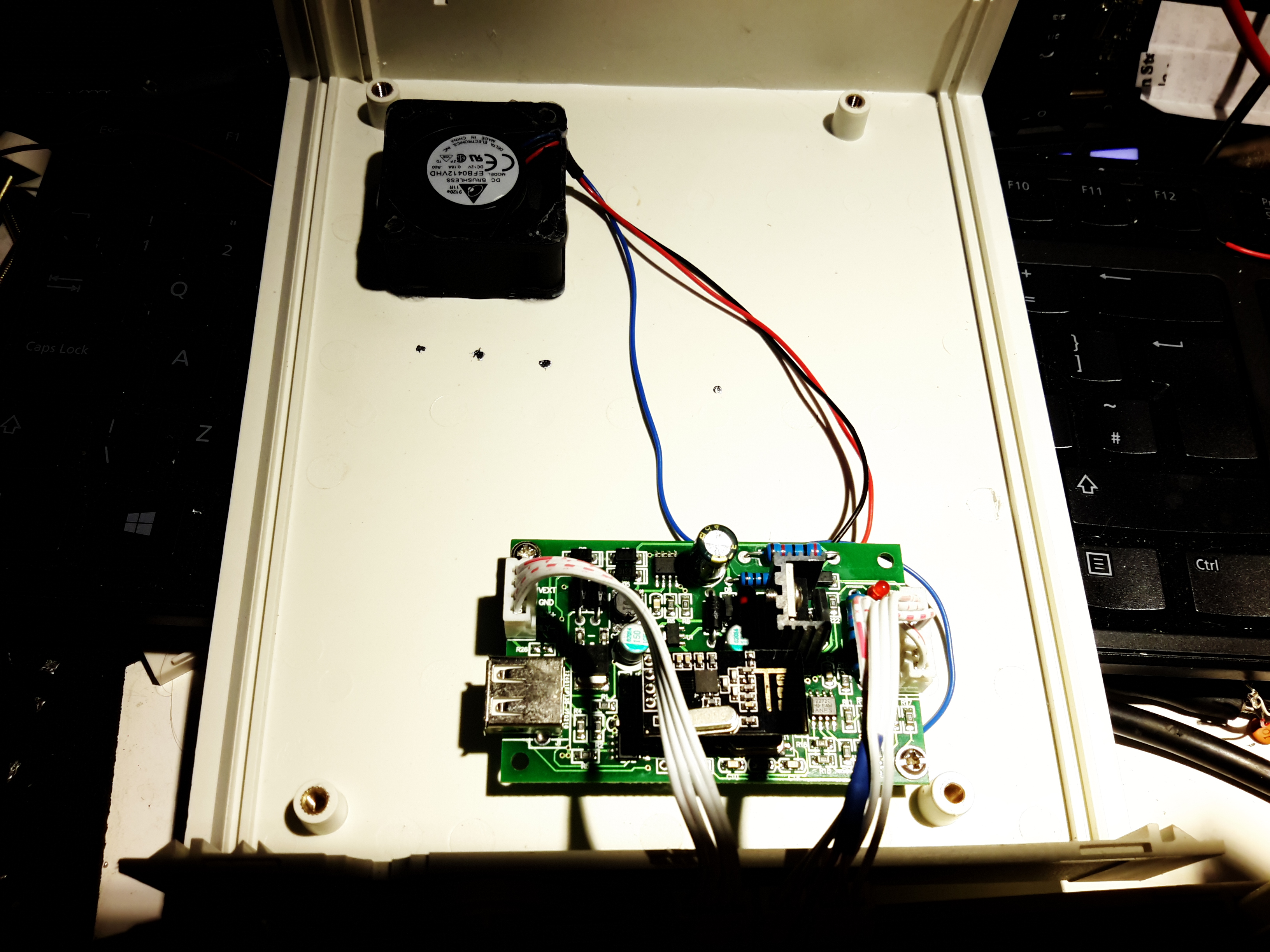
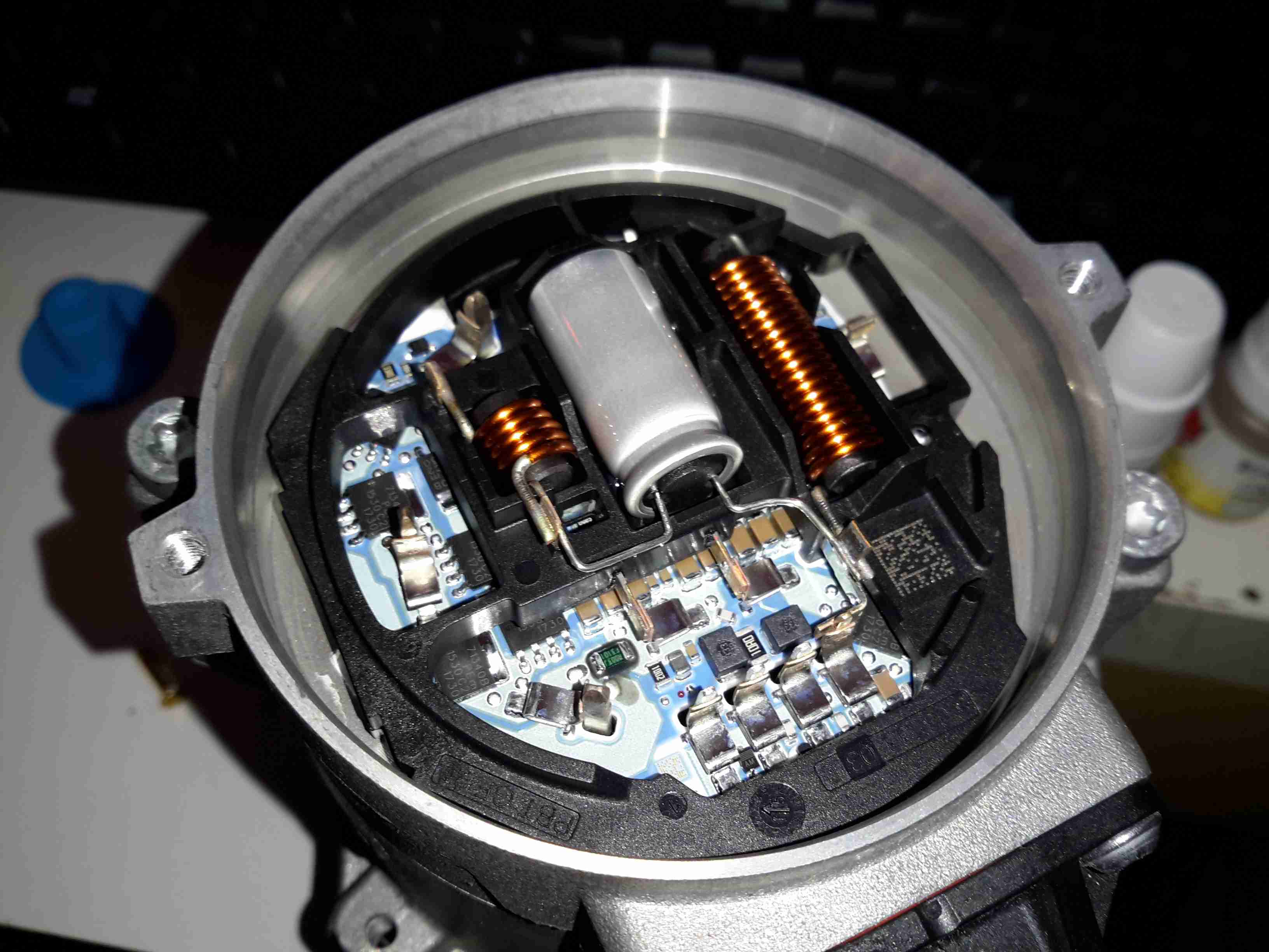
The Sterling charger we’ve had on board nb Tanya Louise since Feb 2014 has bitten the dust, with 31220 hours on it’s internal clock. Since we’re a liveaboard boat, this charger has had a lot of use while we’re on the mooring during winter, when the solar bank isn’t outputting it’s full rate. First, a bit of a teardown to explore the unit, then onto the repair:
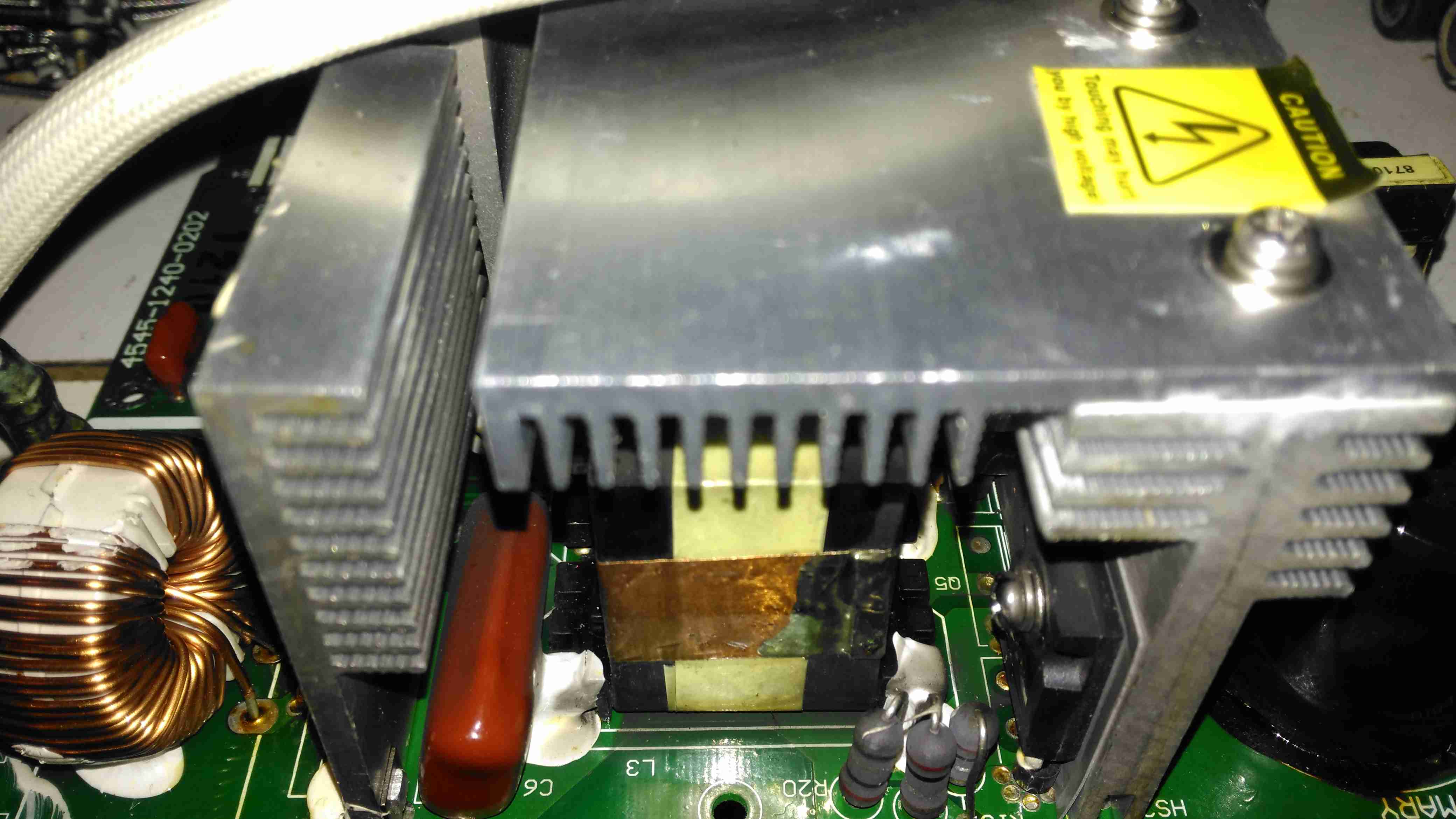
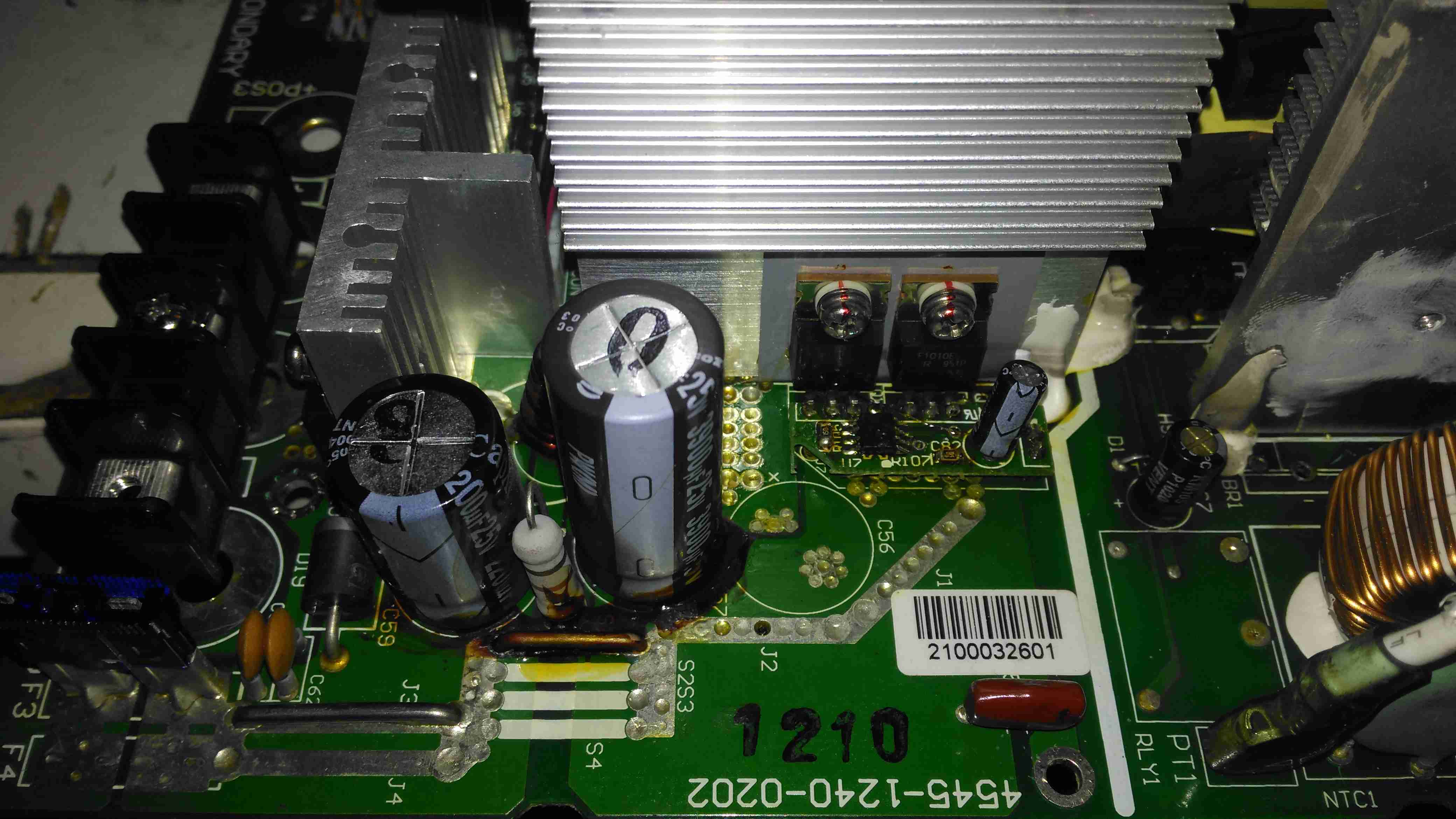
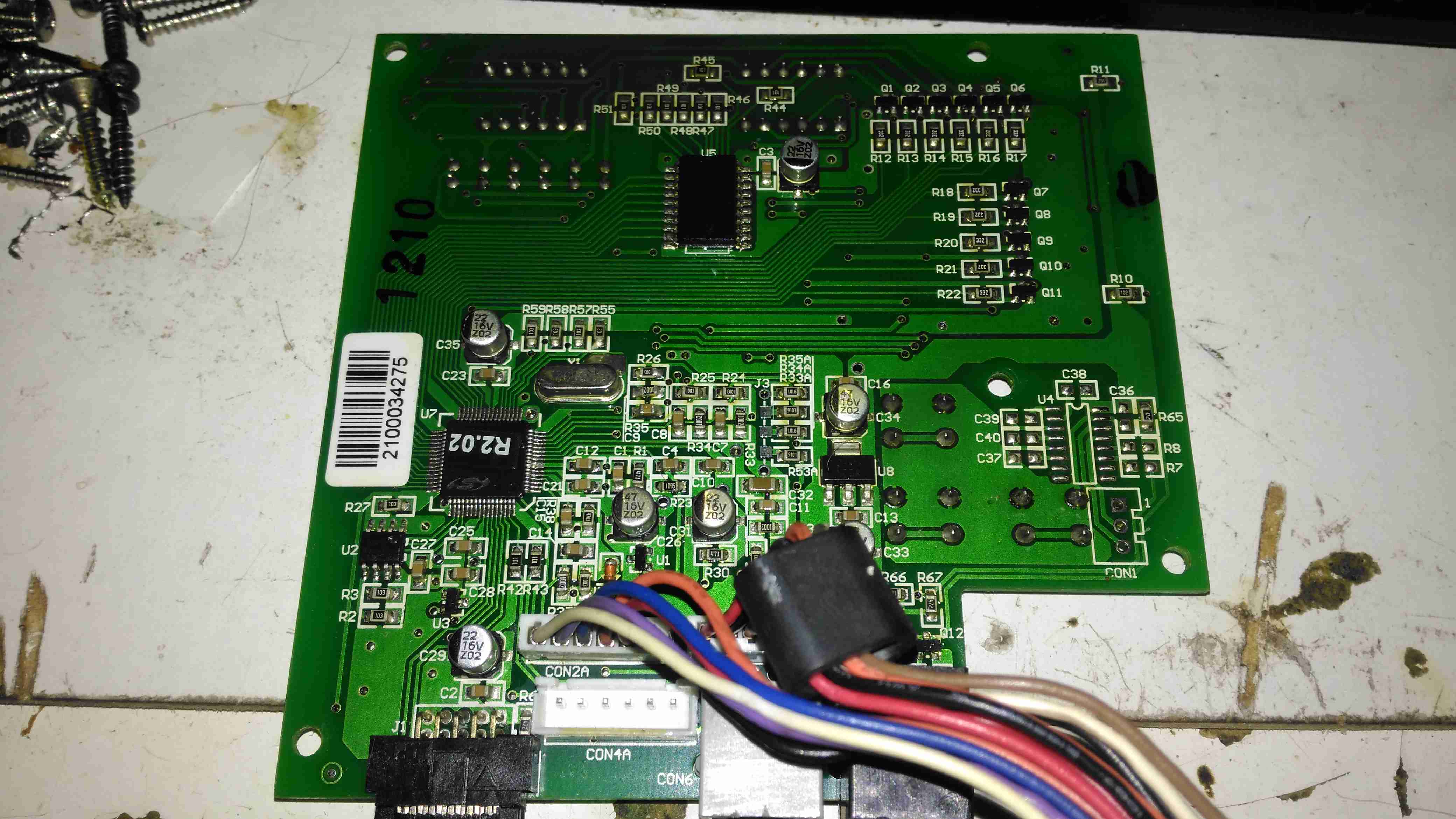
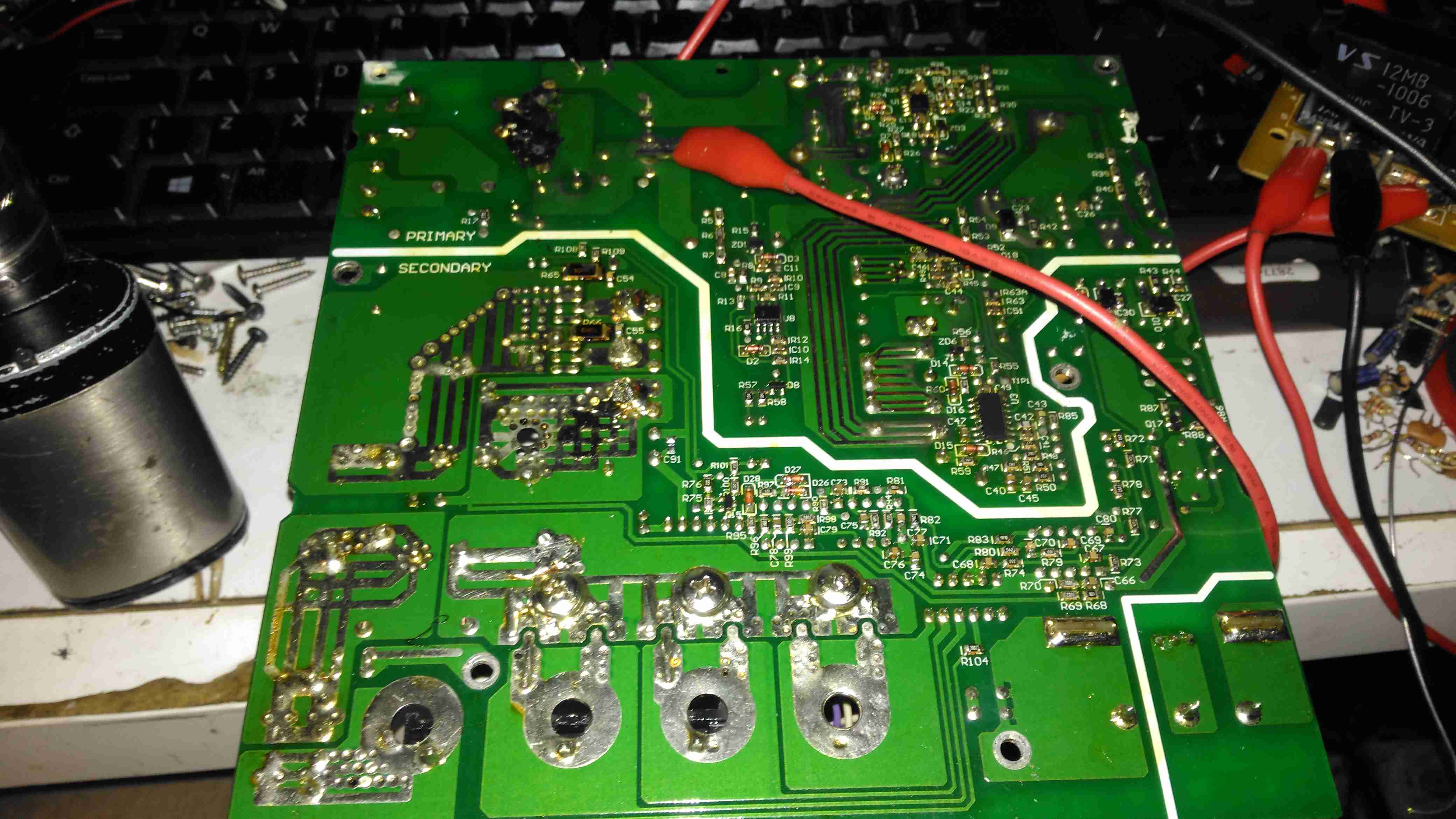
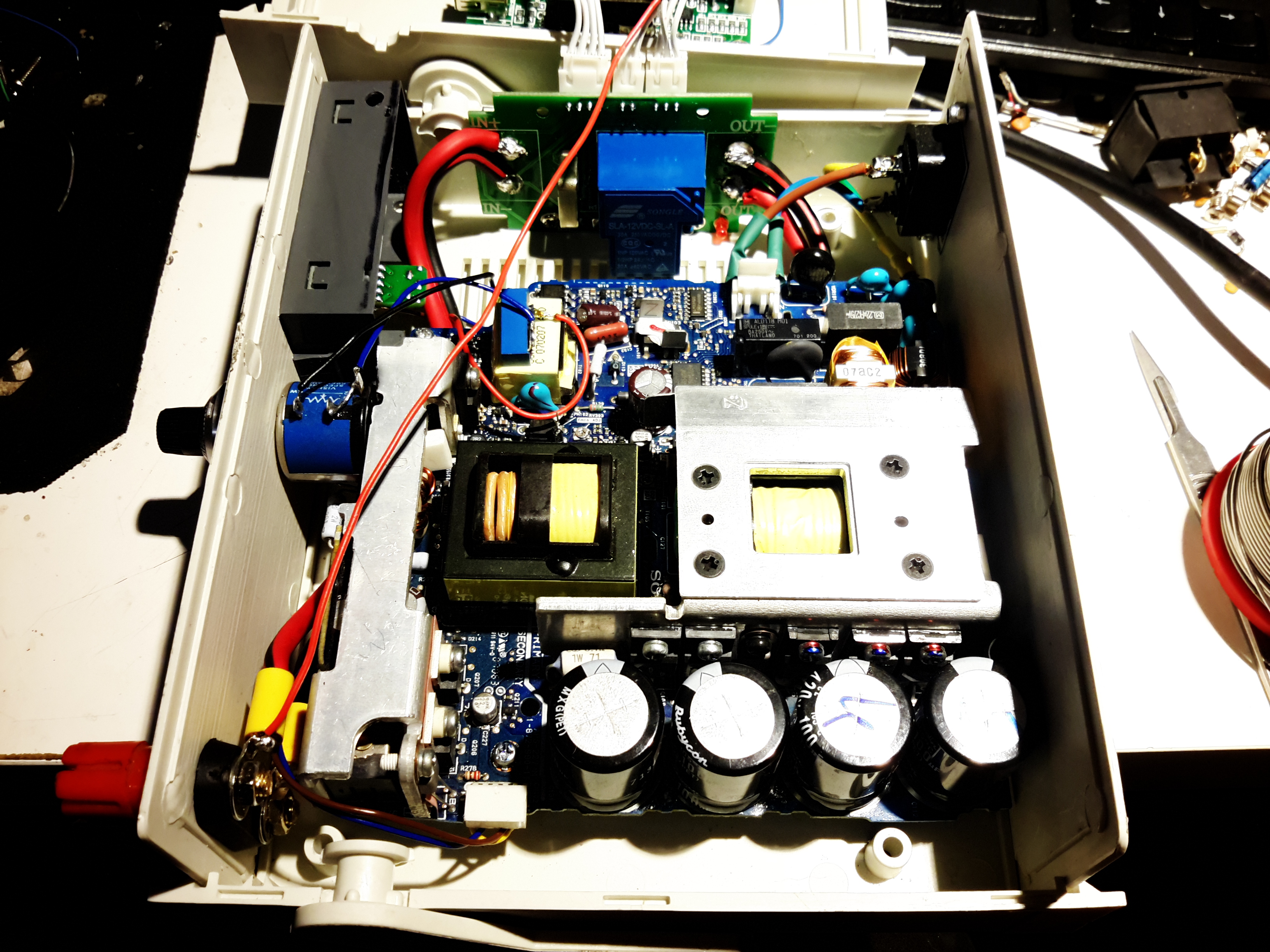
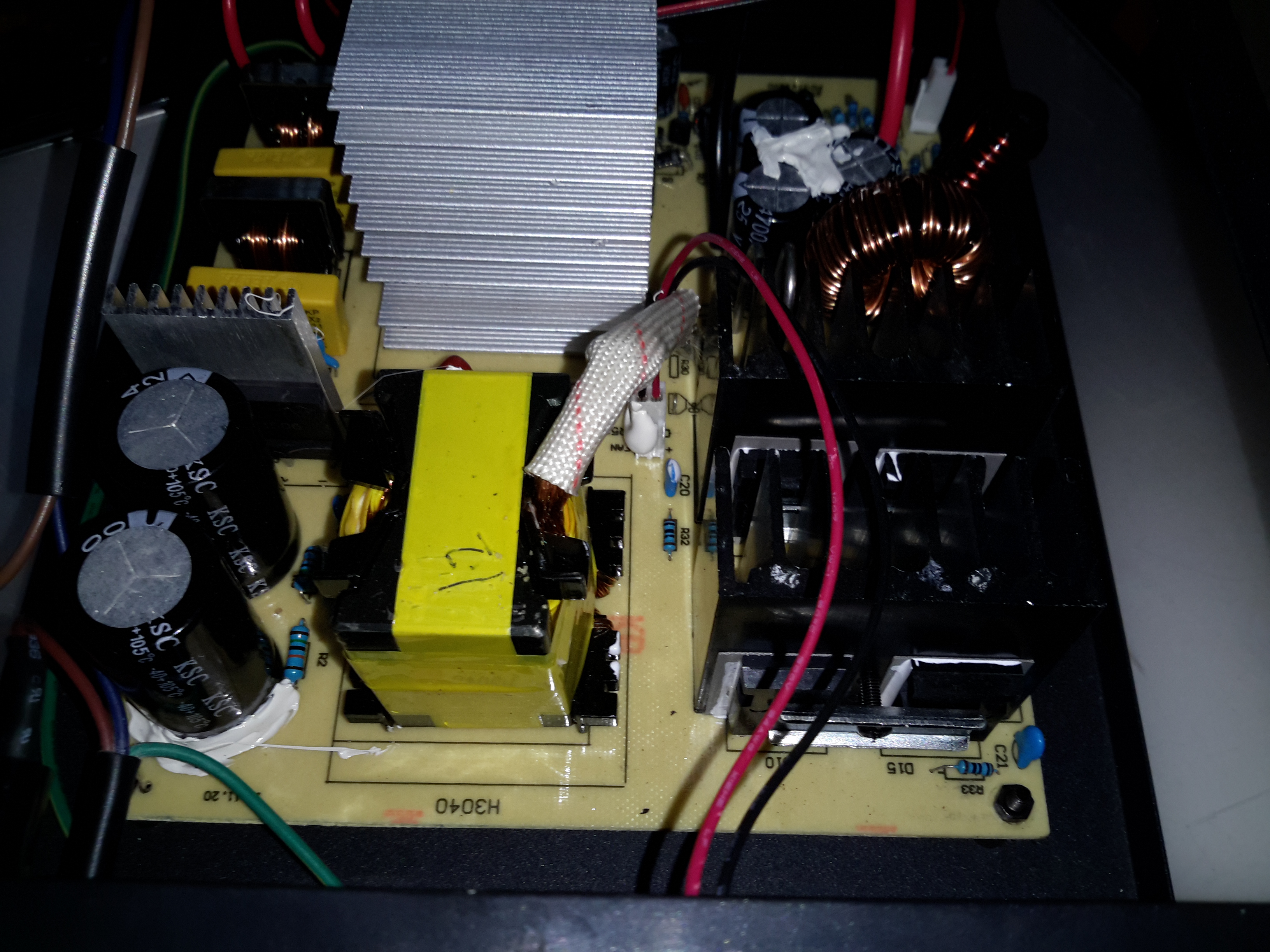
Active PFC Section
There’s the usual mains input filtering on the left, with the bridge rectifier on it’s heatsink.
Underneath the centre massive heatsinks is the main transformer (not visible here) & active PFC circuit. The device peeking out from underneath is the huge inductor needed for PFC. It’s associated switching MOSFET is to the right.
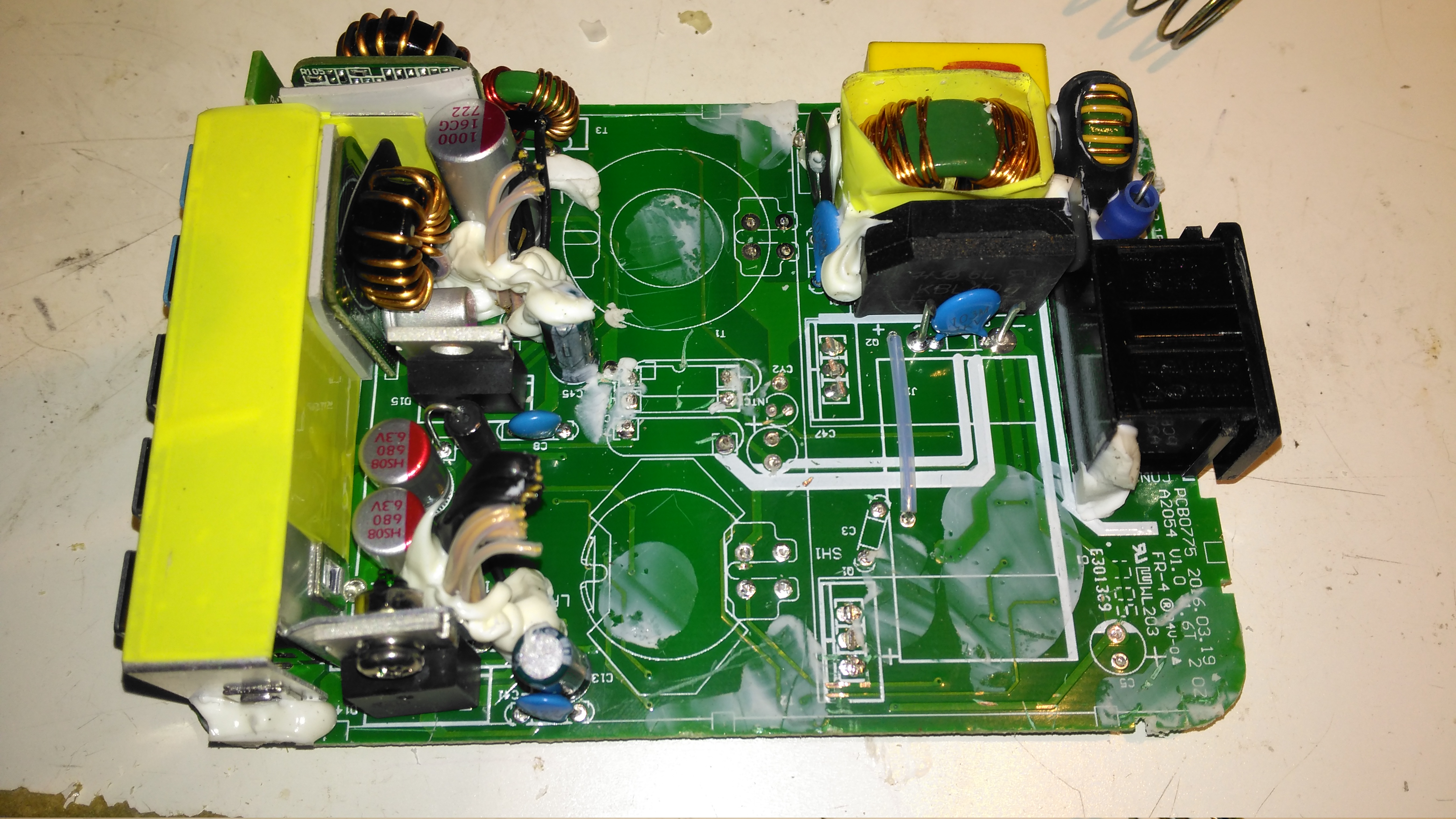
Logic PSU Section
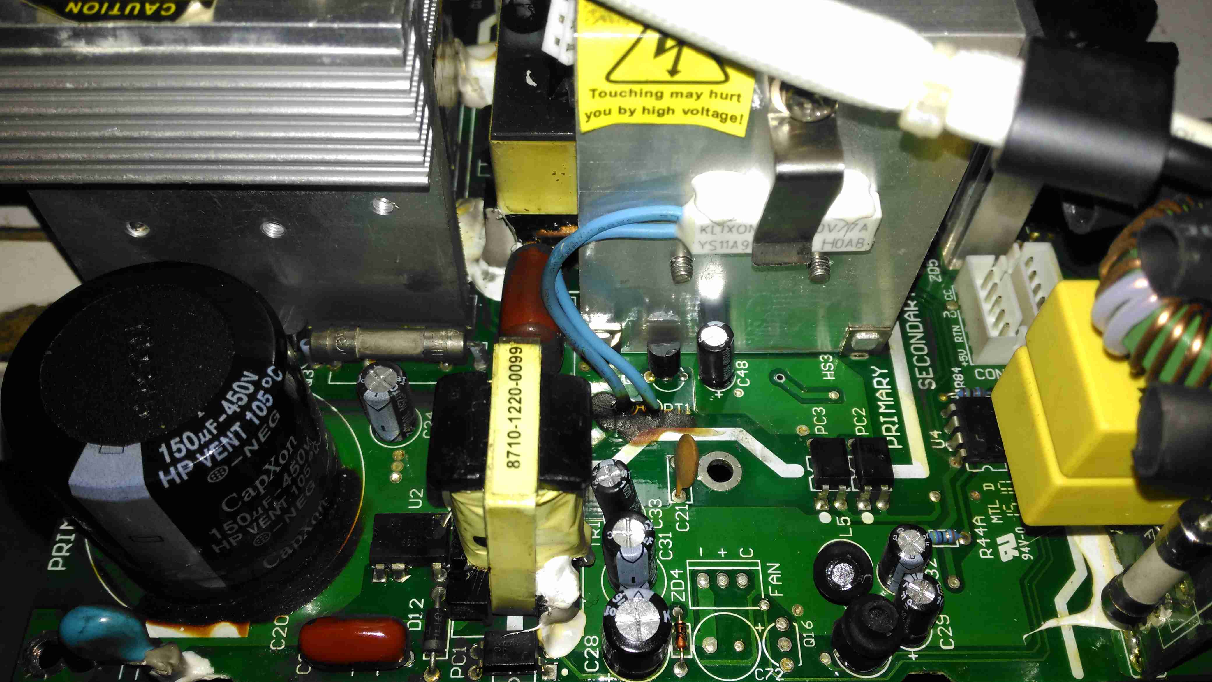
On the other side of the PFC section is the main DC rail filter electrolytic, a 450v 150µF part. Here some evidence of long-term heating can be seen in the adhesive around the base, it’s nearly completely turned black! It’s not a decent brand either, a Chinese CapXon.
The PCB fuse just behind it is in the DC feed to the main switching supply, so the input fuse only protects the filter & Active PFC circuitry. Luckily this fuse didn’t blow during the failure, telling me the fault was earlier in the power chain.
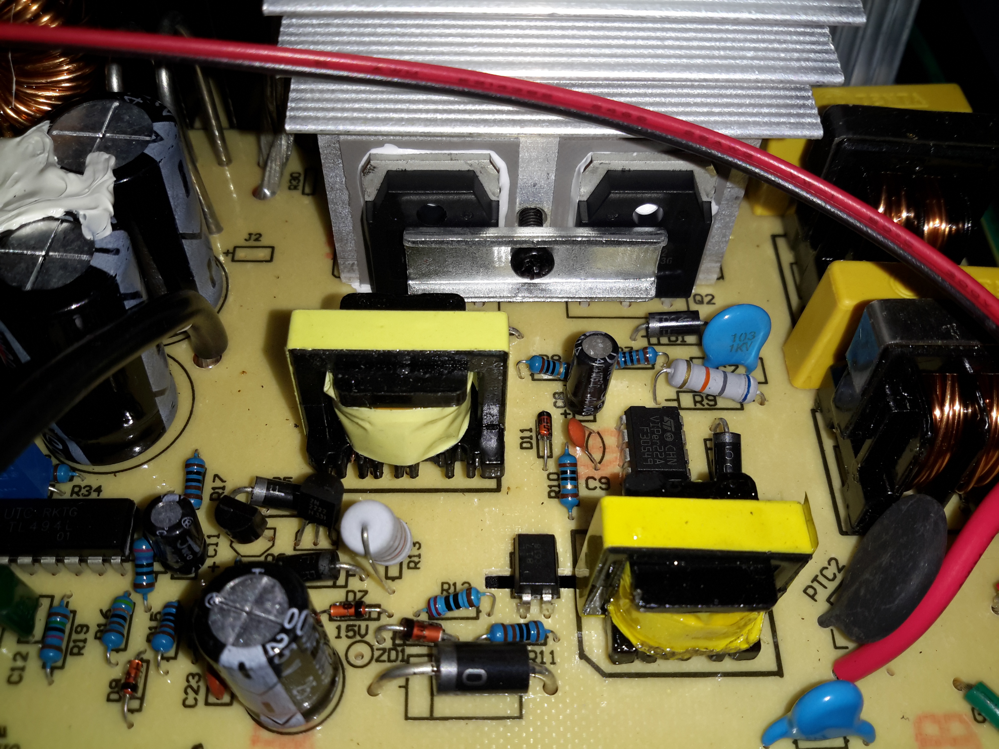
The logic circuits are powered by an independent switching supply in the centre, providing a +5v rail to the microcontroller. The fan header & control components are not populated in this 10A model, but I may end up retrofitting a fan anyway as this unit has always run a little too warm. The entire board is heavily conformal coated on both sides, to help with water resistance associated with being in a marine environment. This has worked well, as there isn’t a single trace of moisture anywhere, only dust from years of use.
There is some thermal protection for the main SMPS switching MOSFETS with the Klixon thermal fuse clipped to the heatsink.
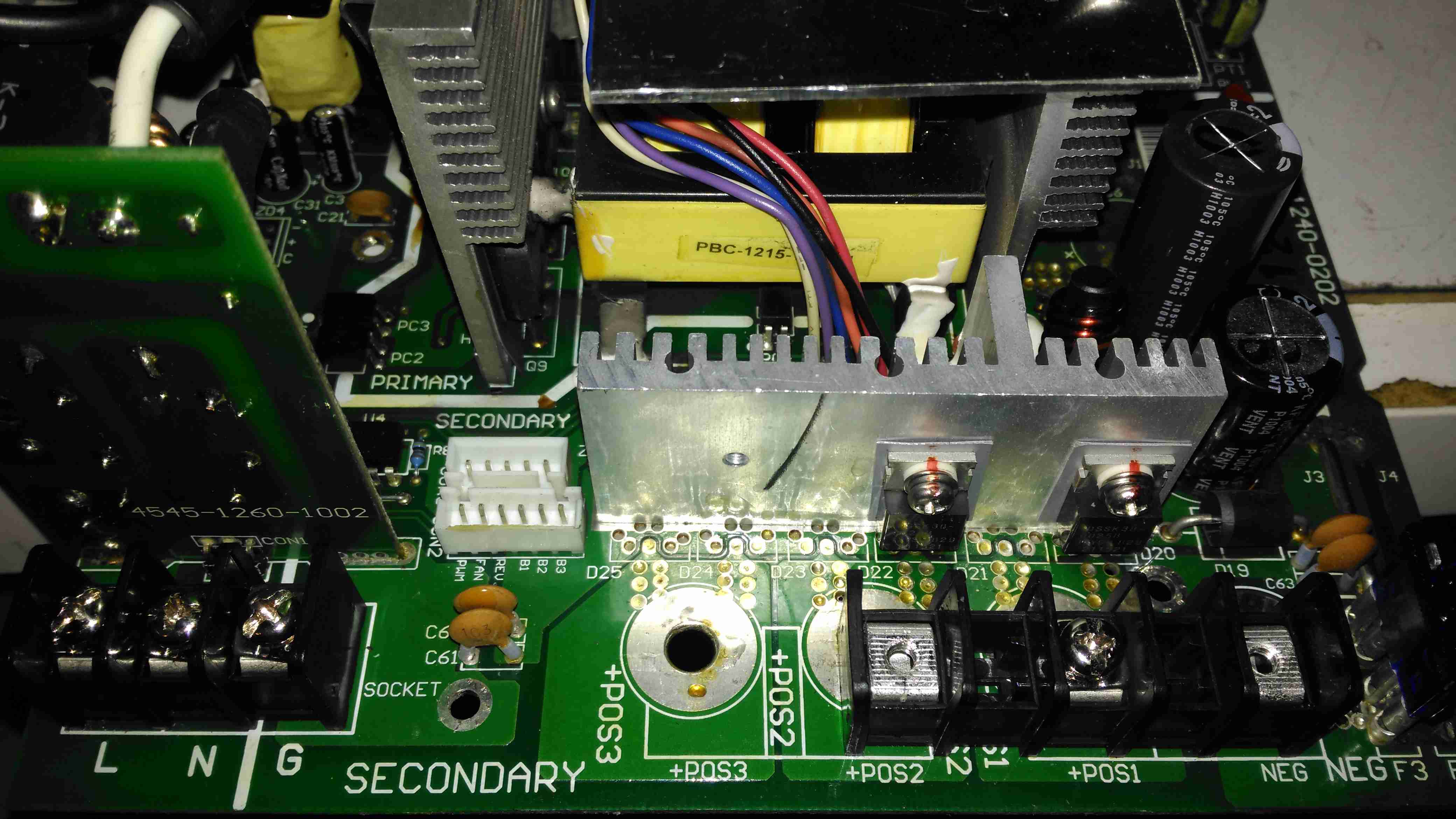
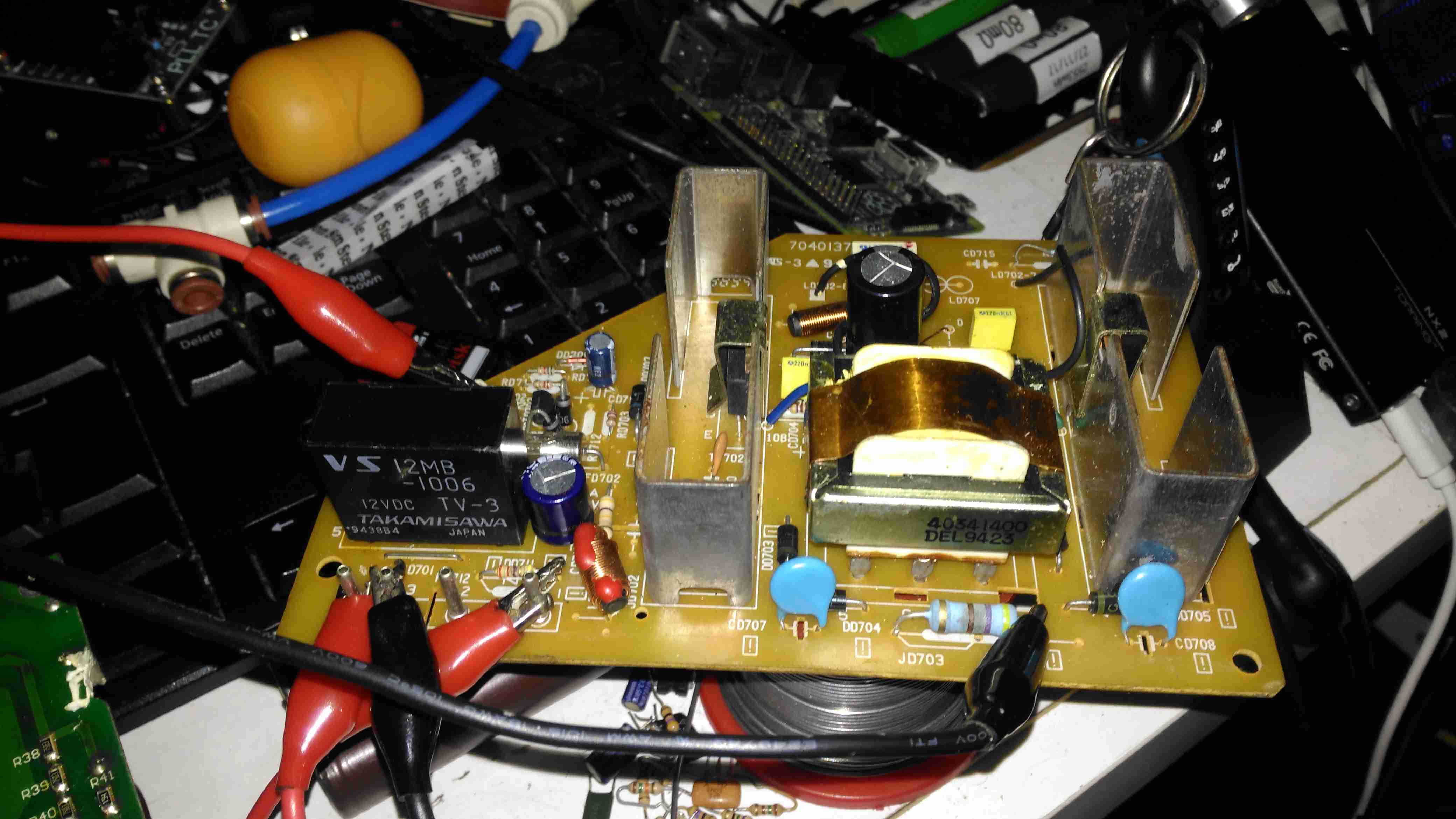
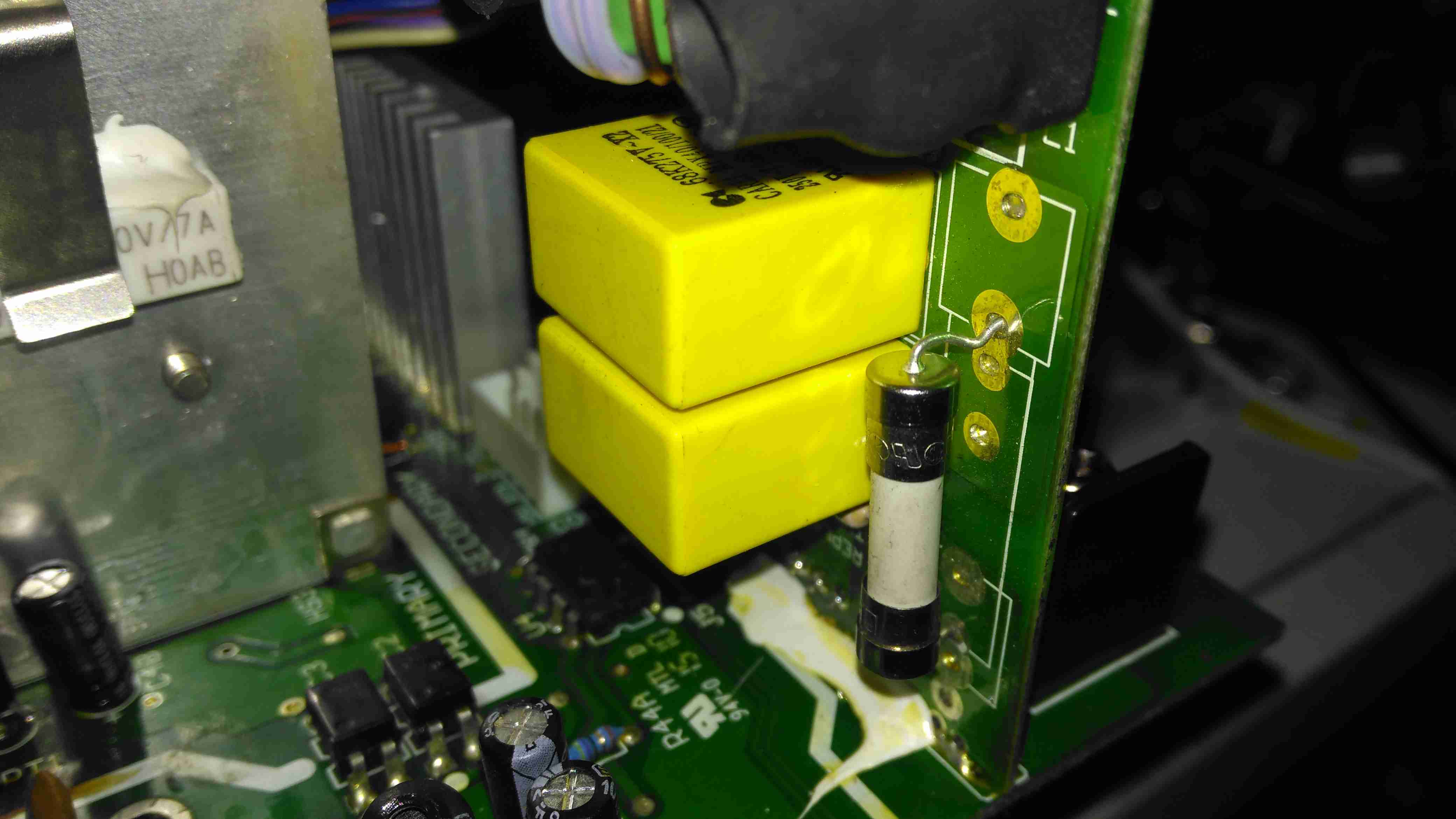
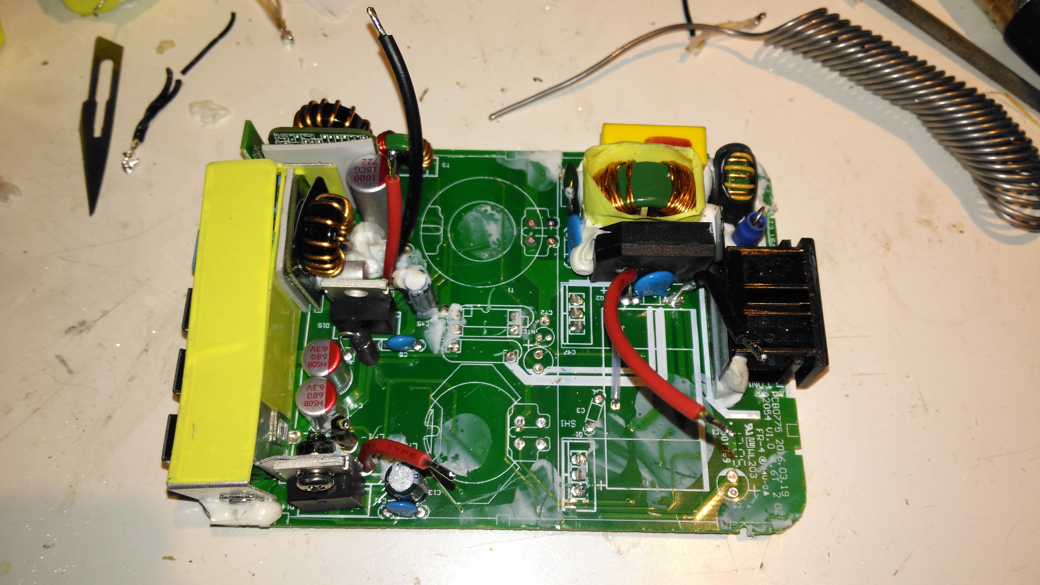
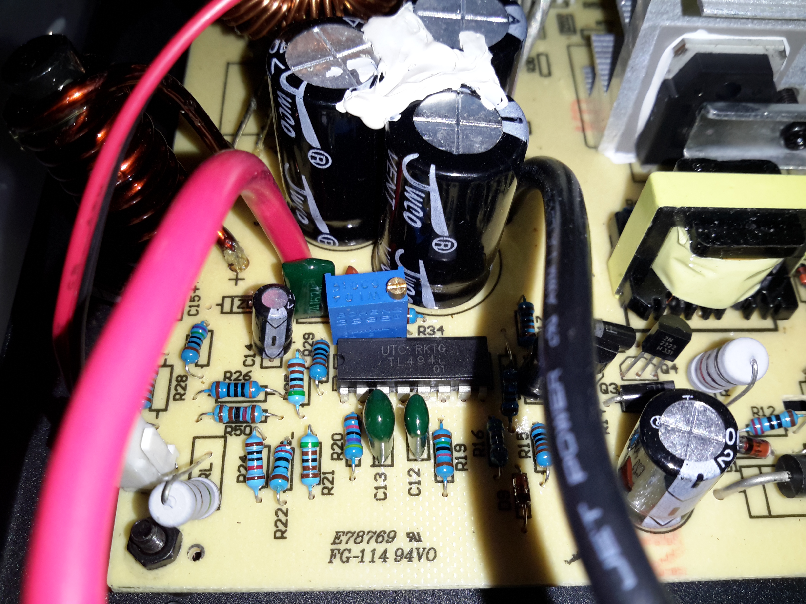
DC Output Section
The DC output rectifiers are on the large heatsink in the centre, with a small bodge board fitted. Due to the heavy conformal coating on the board I can’t get the ID from this small 8-pin IC, but from the fact that the output rectifiers are in fact IRF1010E MOSFETS, rated at 84A a piece, this is an synchronous rectifier controller.
Oddly, the output filter electrolytics are a mix of Nichicon (nice), and CapXon (shite). A bit of penny pinching here, which if a little naff since these chargers are anything but cheap. (£244.80 at the time of writing).
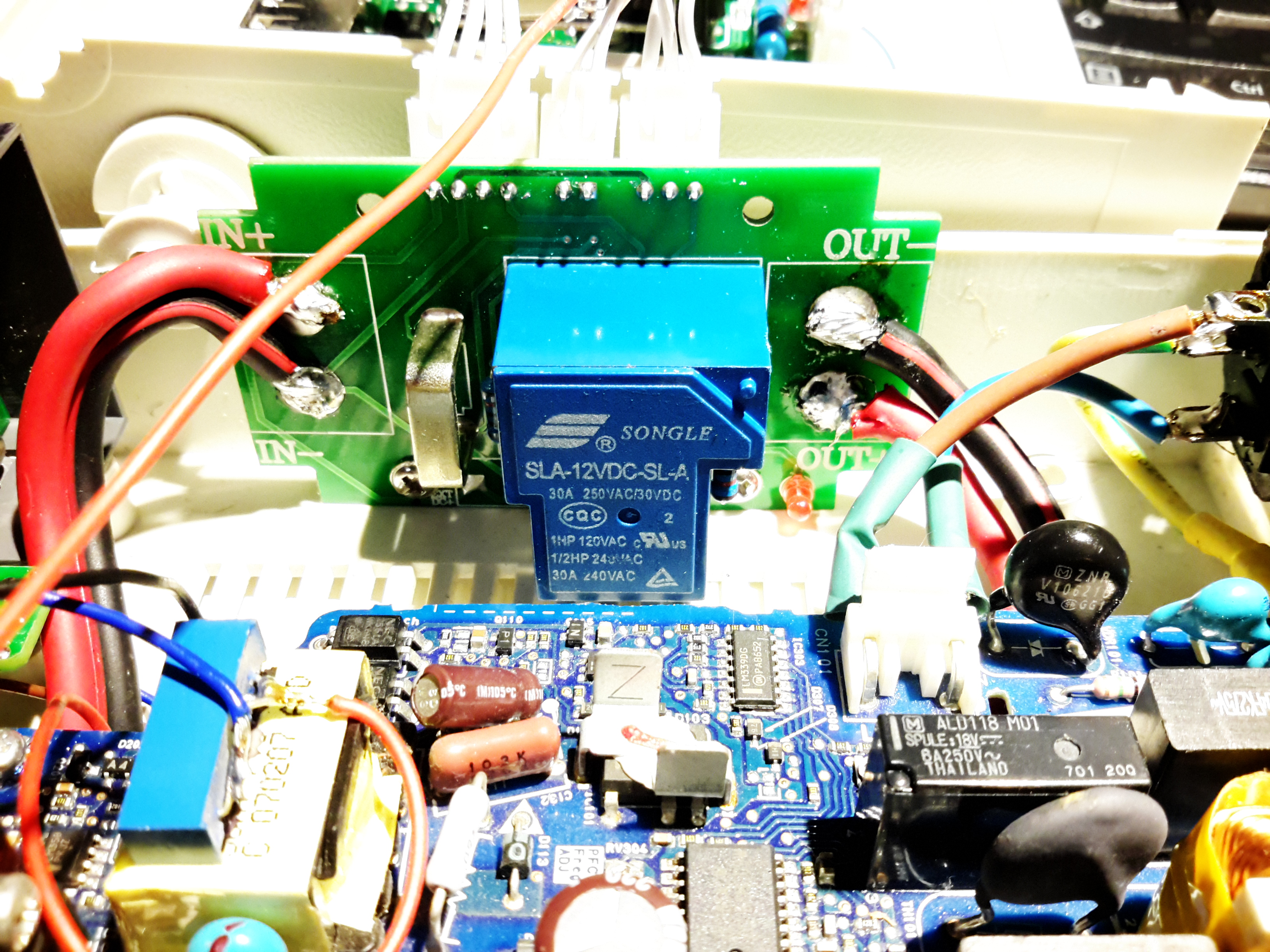
Hiding just behind the electrolytics is a large choke, and a reverse-polarity protection diode, which is wired crowbar-style. Reversing the polarity here will blow the 15A DC bus fuse instantly, and may destroy this diode if it doesn’t blow quick enough.
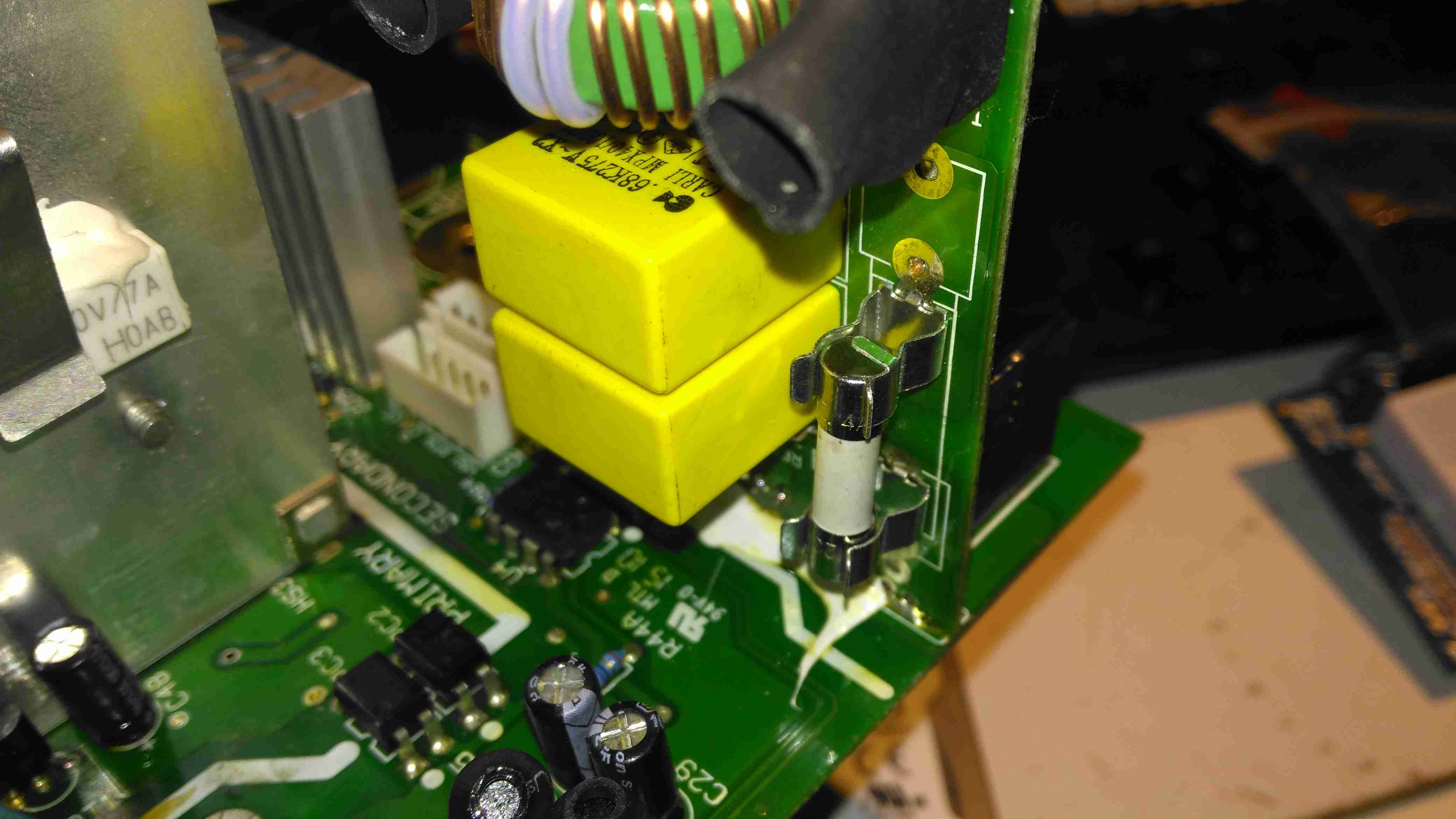
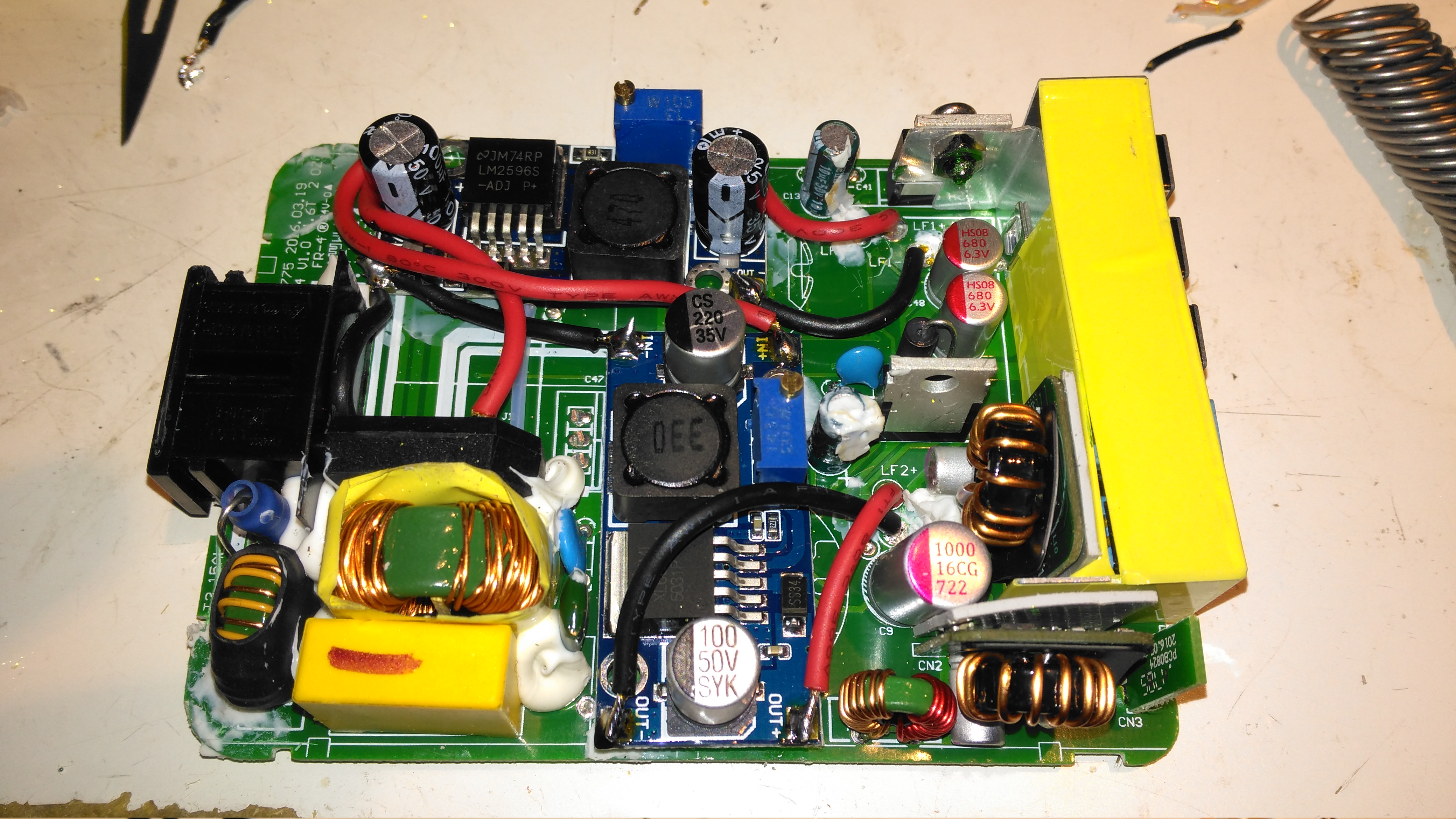
DC Outputs
Right on the output end are a pair of large Ixys DSSK38 TO220 Dual 20A dual Schottky diodes, isolating the two outputs from each other, a nice margin on these for a 10A charger, since the diodes are paralleled each channel is capable of 40A. This prevents one bank discharging into another & allows the charger logic to monitor the voltages individually. The only issue here is the 400mV drop of these diodes introduce a little bit of inefficiency. To increase current capacity of the PCB, the aluminium heatsink is being used as the main positive busbar. From the sizing of the power components here, I would think that the same PCB & component load is used for all the chargers up to 40A, since both the PFC inductor & main power transformer are massive for a 10A output. There are unpopulated output components on this low-end model, to reduce the cost since they aren’t needed.
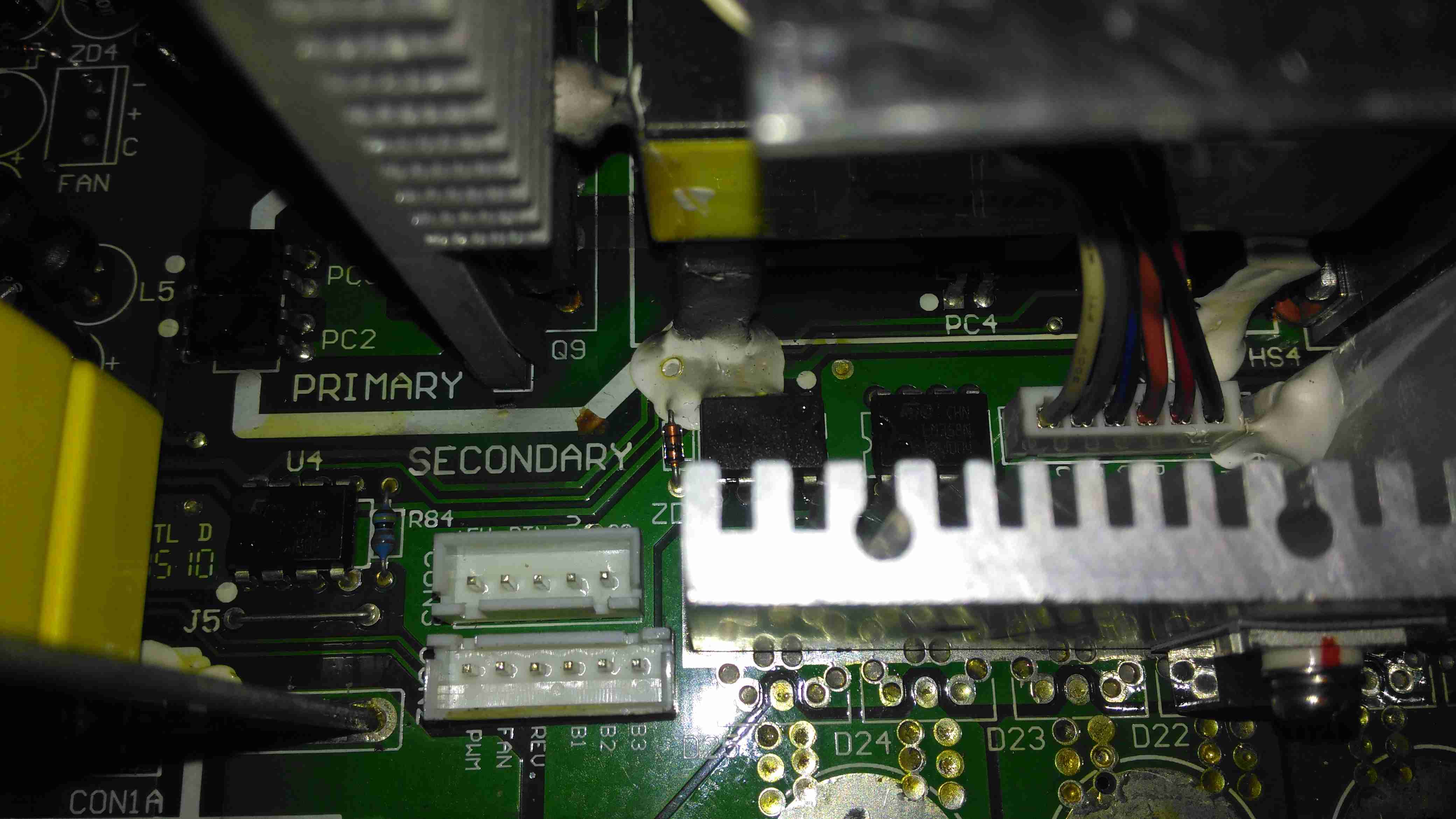
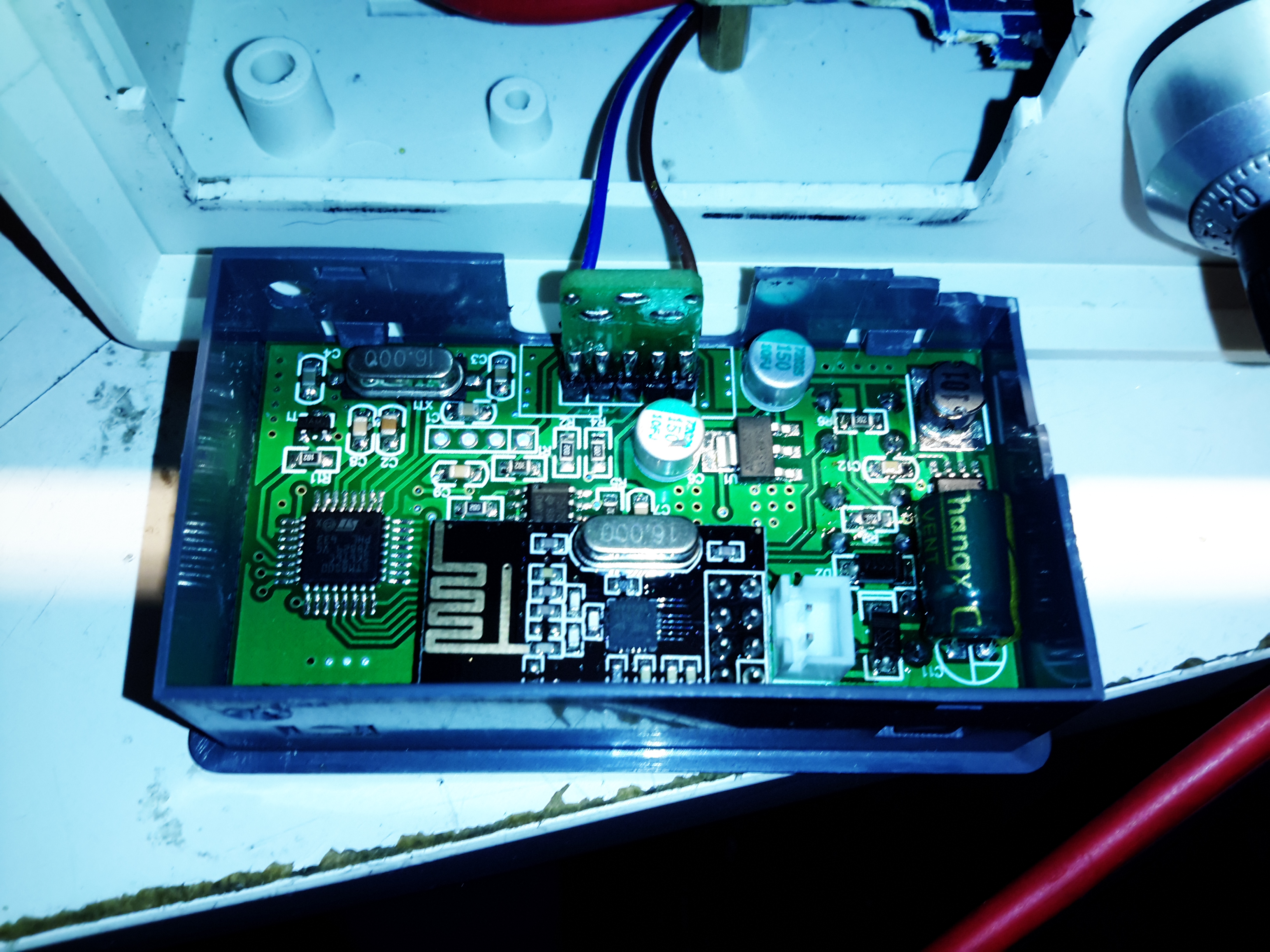
Front Panel Control Connections
A trio of headers connect all the control & sense signals to the front panel PCB, which contains all the control logic. This unit is sensing all output voltages, output current & PSU rail voltages.
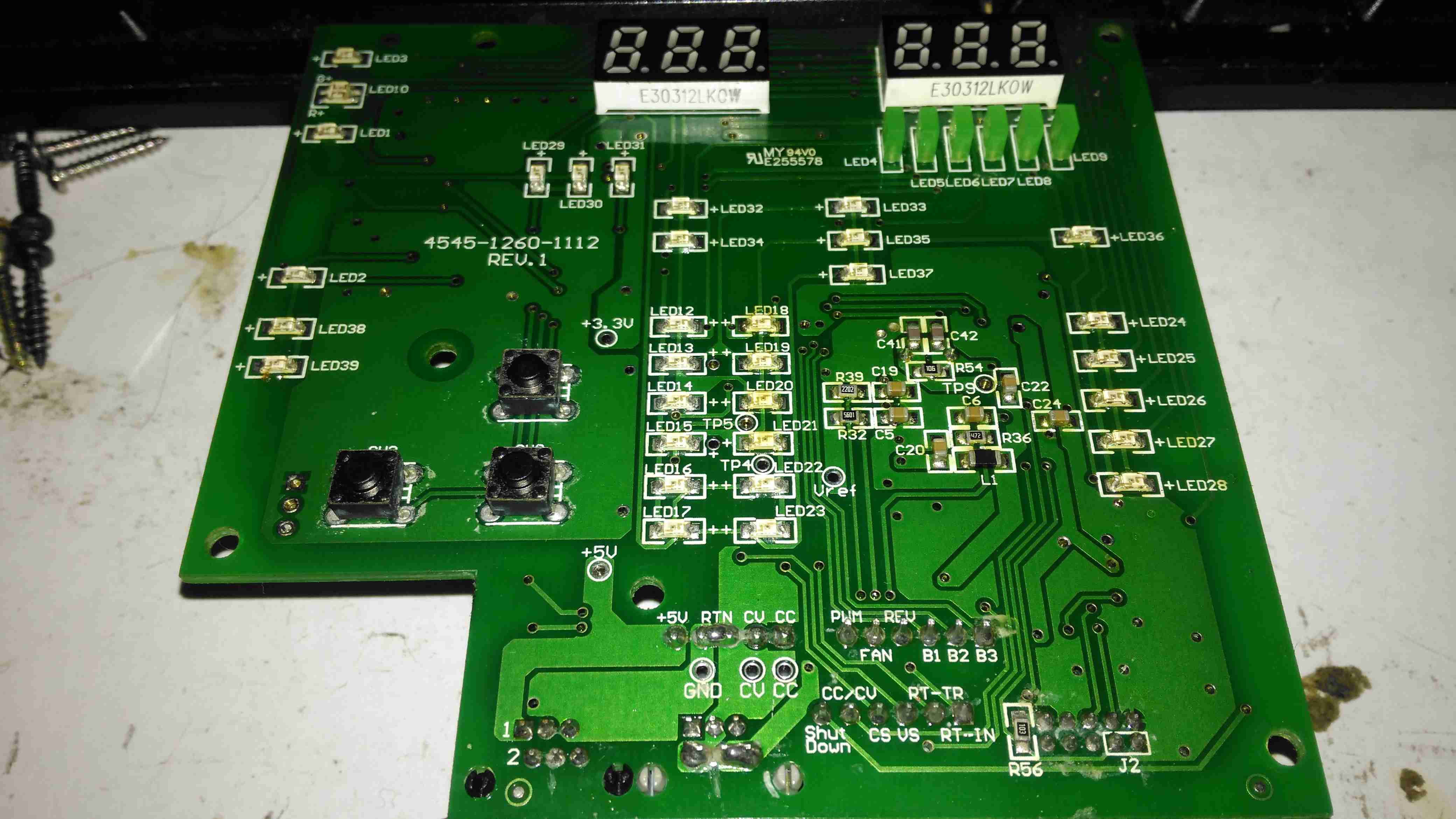
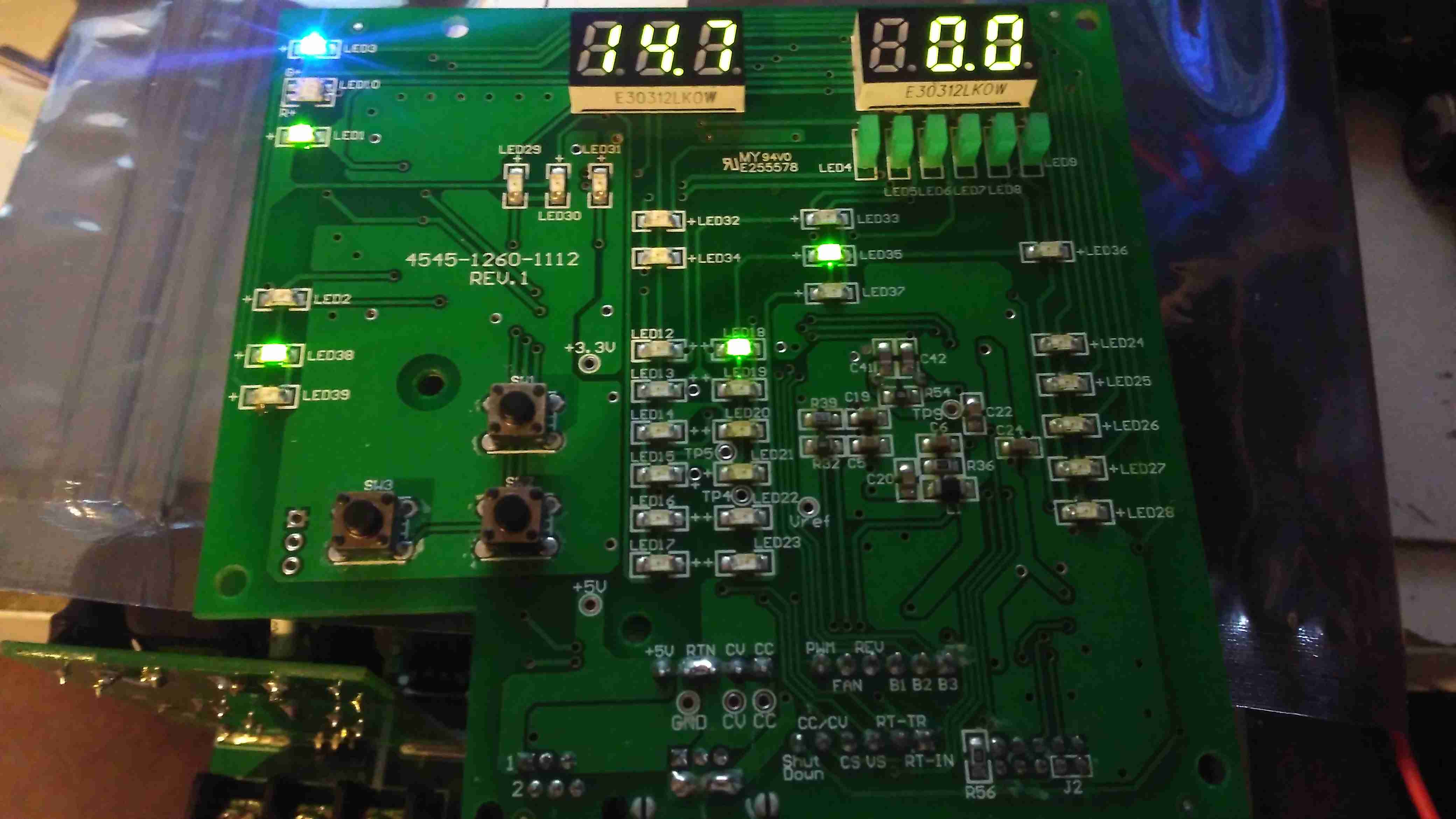
Front Panel LEDs
The front panel is stuffed with LEDs & 7-segment displays to show the current mode, charging voltage & current. There’s 2 tactile switches for adjustments.
Front Panel Reverse
The reverse of the board has the main microcontroller – again identifying this is impossible due to the heavy conformal coat. The LEDs are being driven through a 74HC245D CMOS Octal Bus Transceiver.
Now on to the repair! I’m not particularly impressed with only getting 4 years from this unit, they are very expensive as already mentioned, so I would expect a longer lifespan. The input fuse had blown in this case, leaving me with a totally dead charger. A quick multimeter test on the input stage of the unit showed a dead short – the main AC input bridge rectifier has gone short circuit.
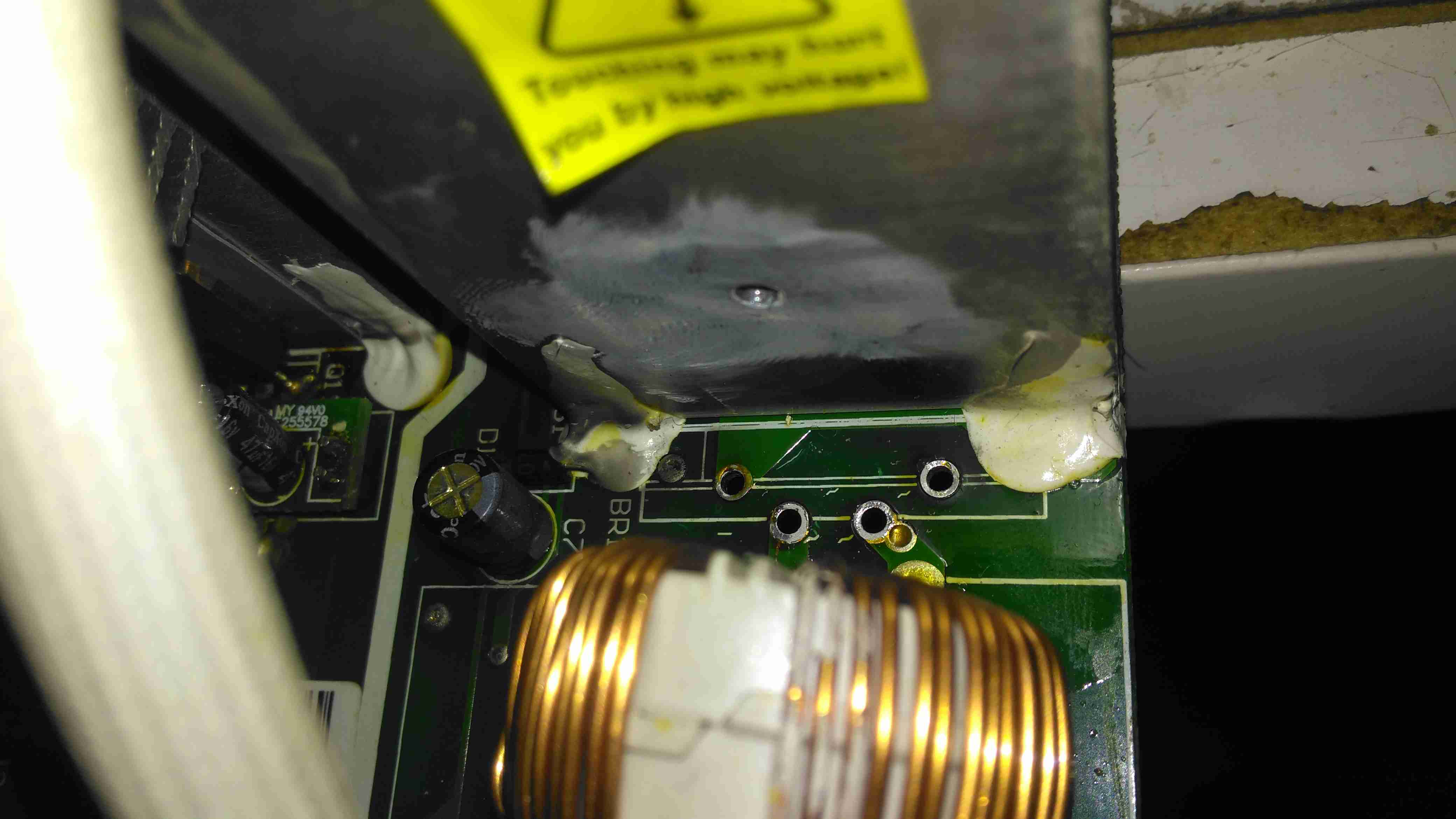
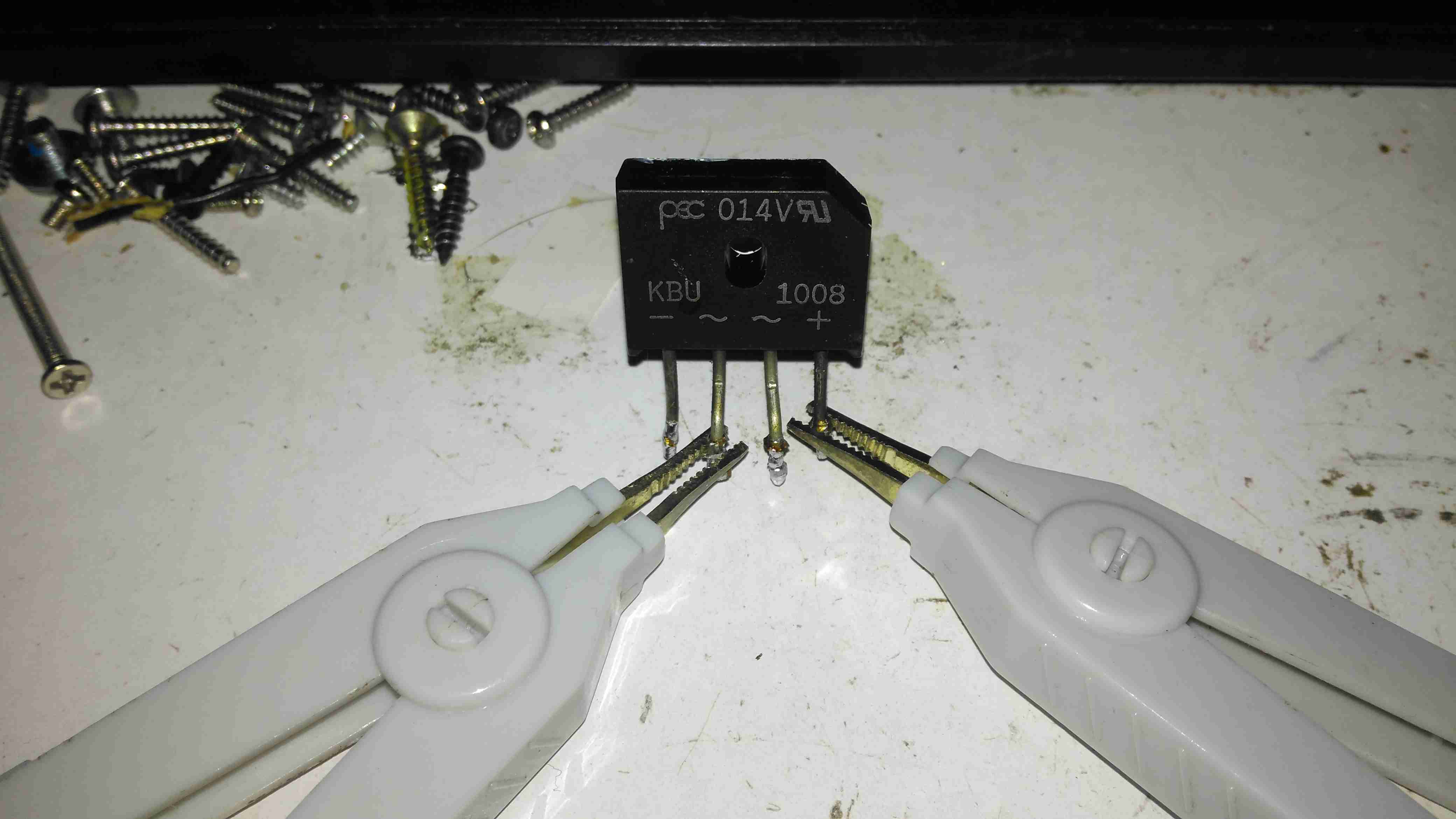
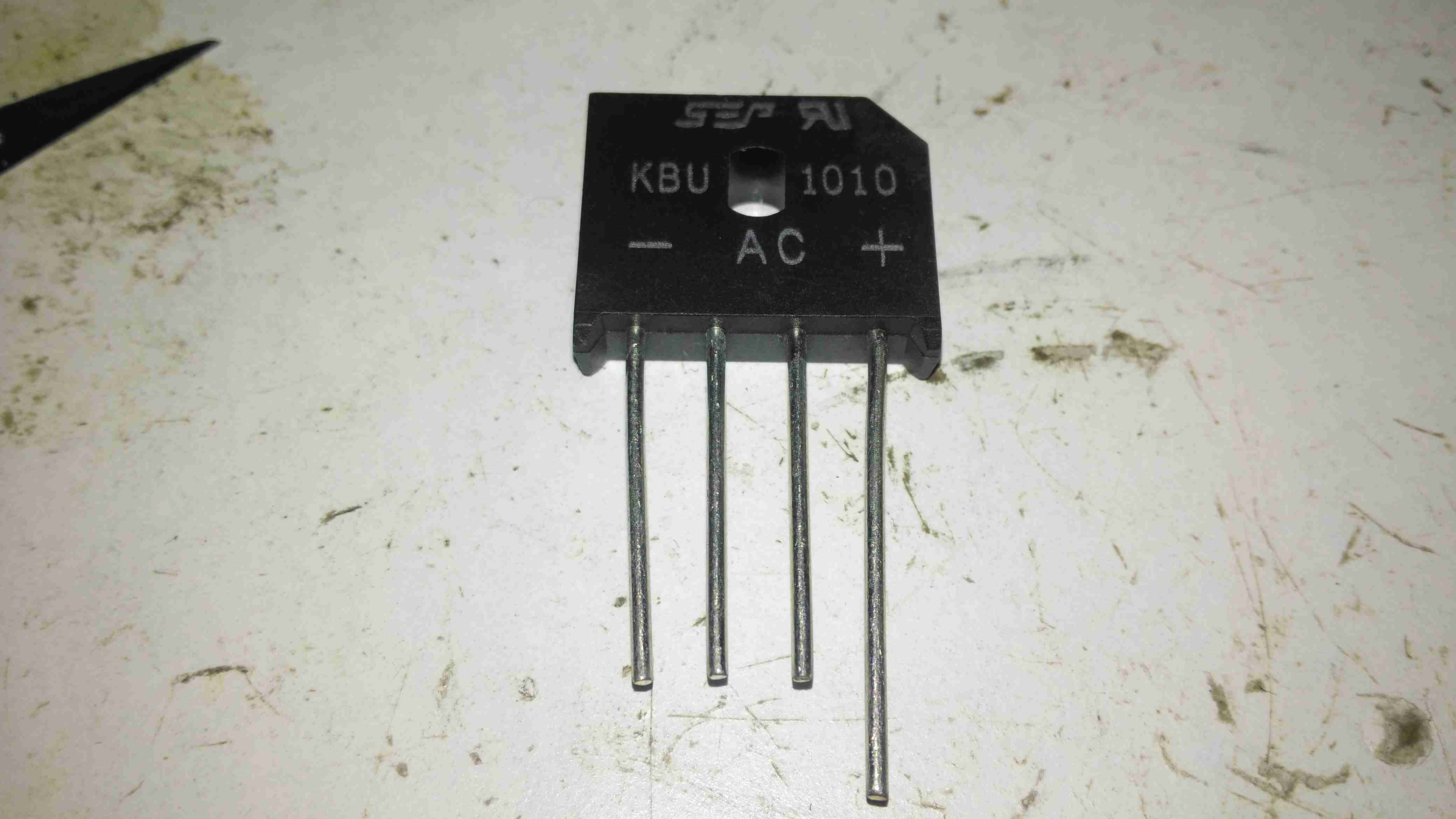
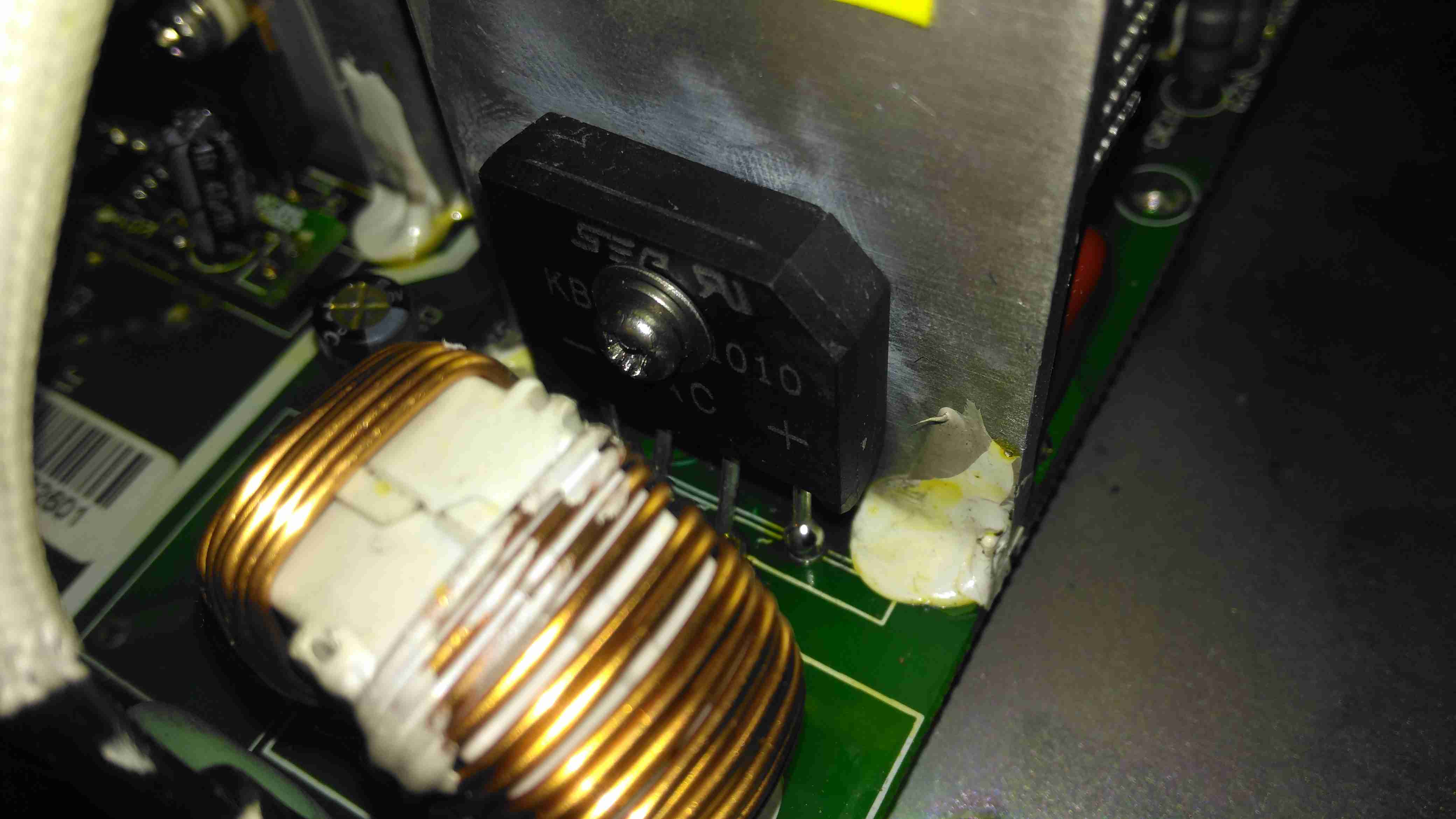
Bridge Rectifier Removed
Here the defective bridge has been desoldered from the board. It’s a KBU1008 10A 800v part. Once this was removed I confirmed there was no longer an input short, on either the AC side or the DC output side to the PFC circuit.
Testing The Rectifier
Time to stick the desoldered bridge on the milliohm meter & see how badly it has failed.
Yep, Definitely Shorted
I’d say 31mΩ would qualify as a short. It’s no wonder the 4A input fuse blew instantly. There is no sign of excessive heat around the rectifier, so I’m not sure why this would have failed, it’s certainly over-rated for the 10A charger.
Testing Without Rectifier
Now the defective diode bridge has been removed from the circuit, it’s time to apply some controlled power to see if anything else has failed. For this I used a module from one of my previous teardowns – the inverter from a portable TV.
Test Inverter
This neat little unit outputs 330v DC at a few dozen watts, plenty enough to power up the charger with a small load for testing purposes. The charger does pull the voltage of this converter down significantly, to about 100v, but it still provides just enough to get things going.
It’s Alive!
After applying some direct DC power to the input, it’s ALIVE! Certainly makes a change from the usual SMPS failures I come across, where a single component causes a chain reaction that writes off everything.
Replacement Rectifier
Unfortunately I couldn’t find the exact same rectifier to replace the shorted one, so I had to go for the KBU1010, which is rated for 1000v instead of 800v, but the Vf rating (Forward Voltage), is the same, so it won’t dissipate any more power.
Soldered In
Here’s the new rectifier soldered into place on the PCB & bolted to it’s heatsink, with some decent thermal compound in between.
Input Board
Here is the factory fuse, a soldered in device. I’ll be replacing this with standard clips for 20x5mm fuses to make replacement in the future easier, the required hole pattern in the PCB is already present. Most of the mains input filtering is also on this little daughterboard.
Fuse Replaced
Now the fuse has been replaced with a standard one, which is much more easily replaceable. This fuse shouldn’t blow however, unless another fault develops.
Full Load Test
Now everything is back together, a full load test charging a 200Ah 12v battery for a few hours will tell me if the fix is good. This charger won’t be going back into service onboard the boat, it’s being replaced anyway with a new 50A charger, to better suit the larger loads we have now. It won’t be a Sterling though, as they are far too expensive. I’ll report back if anything fails!
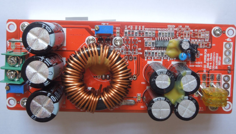
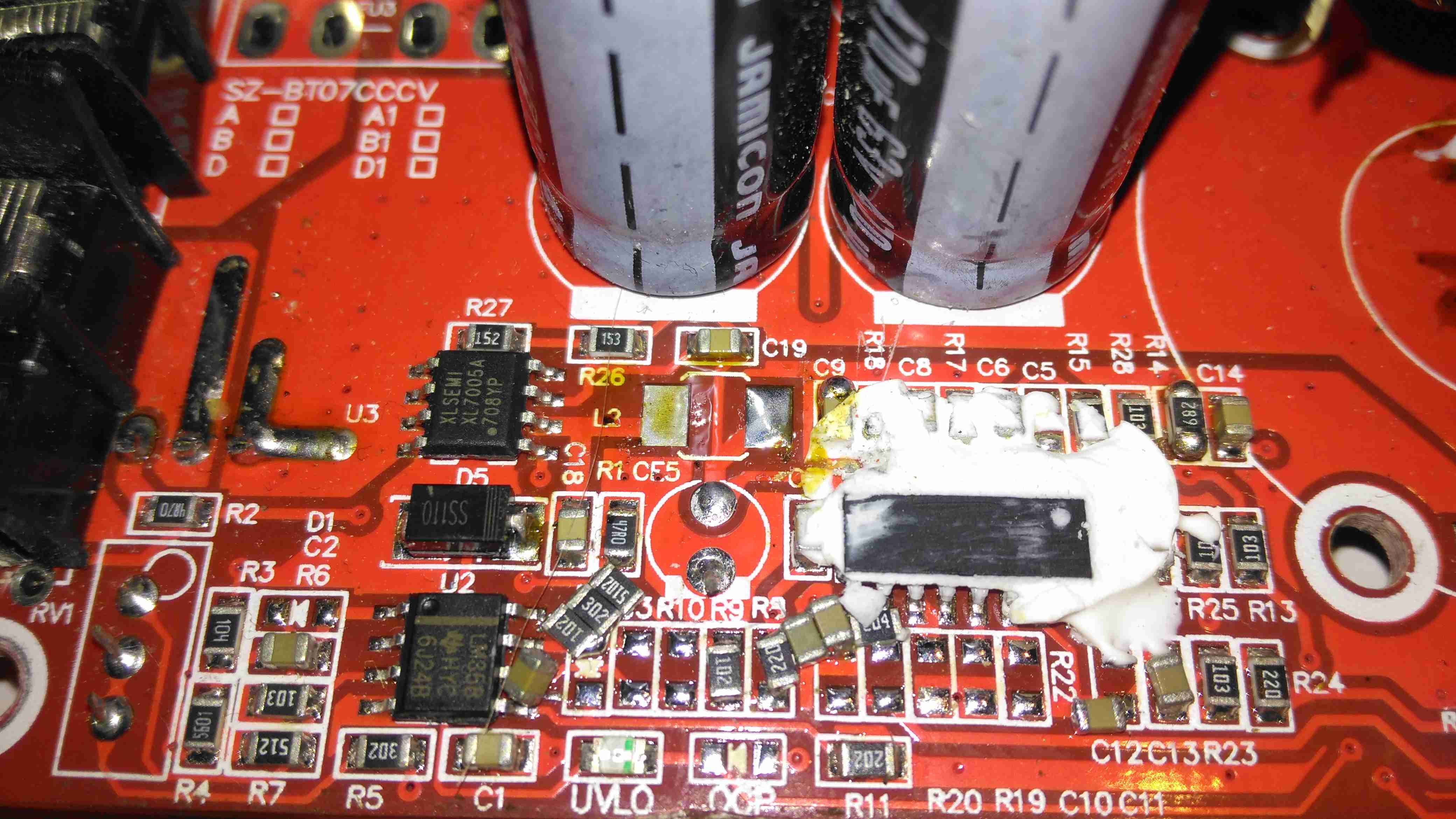
Ah the curse of the Chinese Electronics strikes again. These large DC-DC boost converters have become very common on the likes of AliExpress & eBay, and this time my order has arrived DOA… On applying power, the output LED lights up dimly, and no matter how I twiddle the adjustment pots, the output never rises above the input voltage.
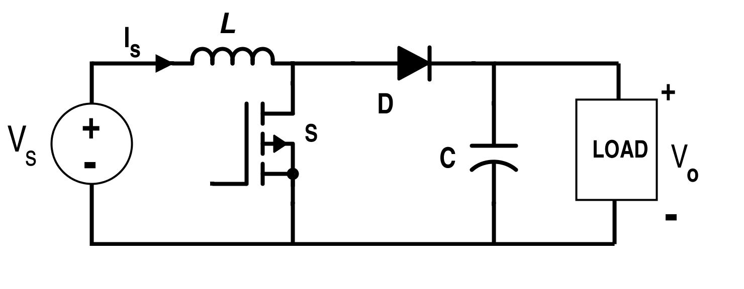
Boost Converter Topology
From the usual topology above, we can assume that the switching converter isn’t working, so the input voltage is just being directly fed through to the output. The switching IC on these converters is a TL494,
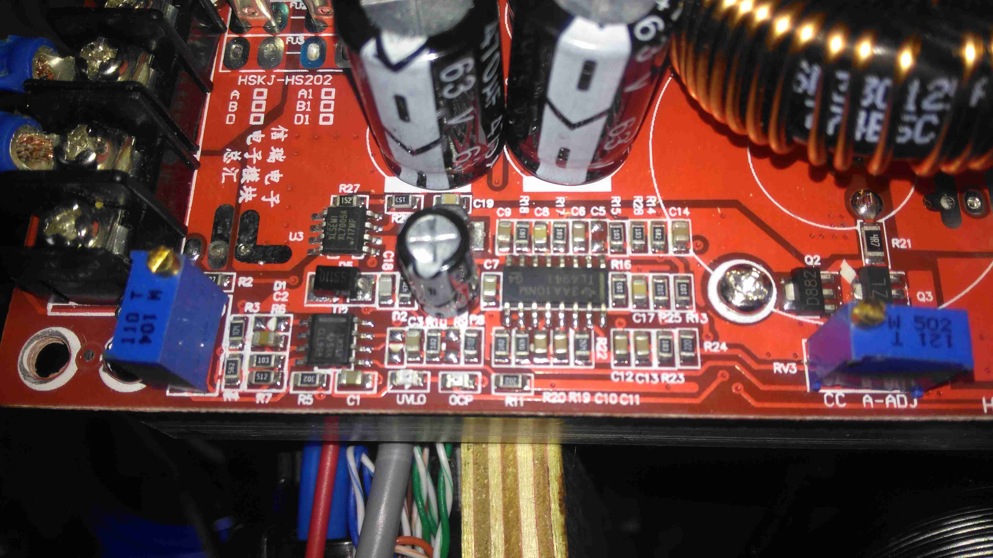
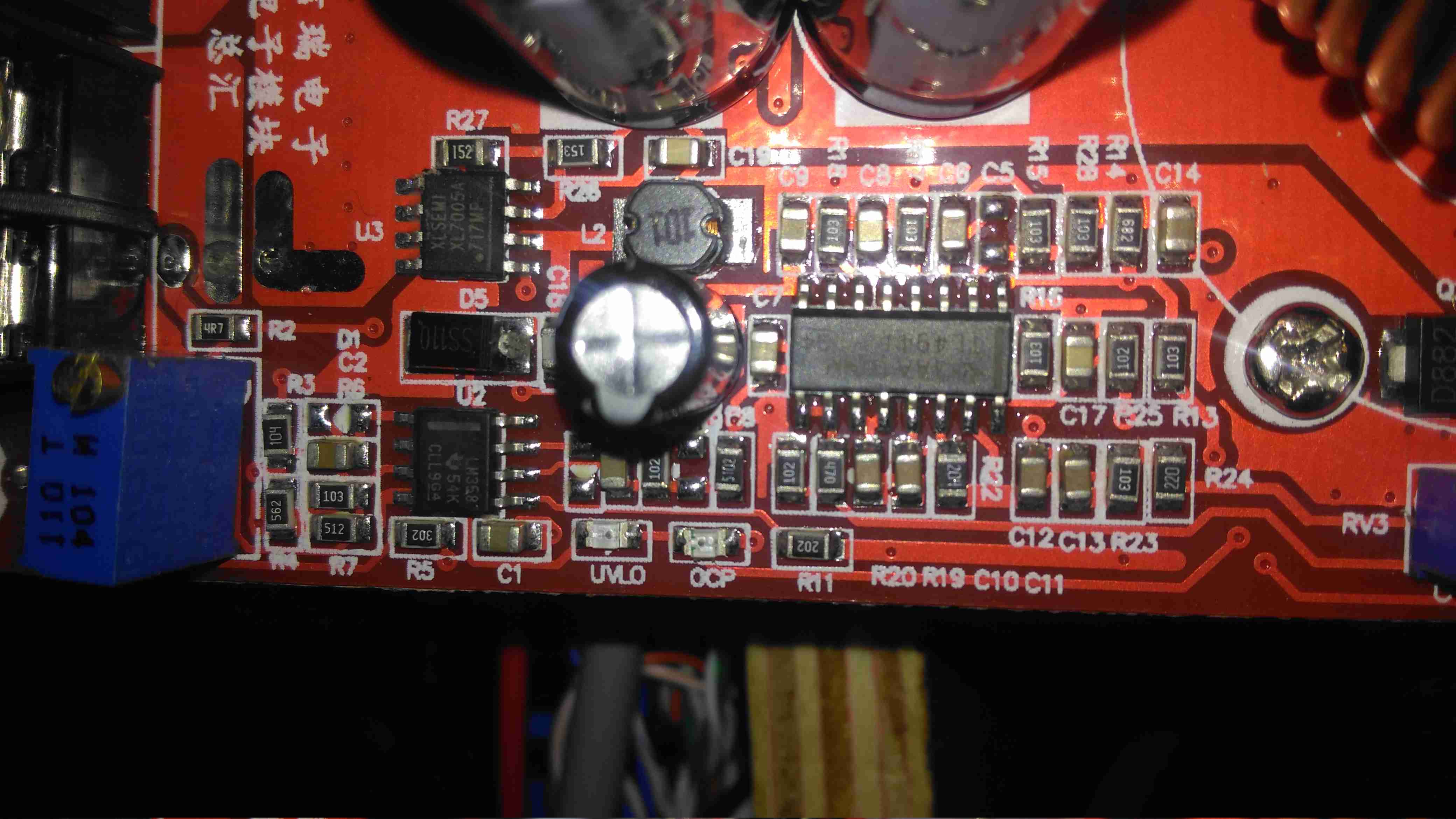
Control Circuitry
The switching IC on these converters is a TL494,with it’s surrounding support components, including a LM358 dual Op-Amp. Power for this lot is supplied from the input via a small DC-DC converter controlled by an XL Semi XL7001 Buck Converter IC. Some testing revealed that power was getting to the XL7001, but the output to the switching controller was at zero volts.
Inductor
The 100µH inductor for this buck converter is hidden behind the output electrolytic, and a quick prod with a multimeter revealed this inductor to be open circuit. That would certainly explain the no-output situation. Luckily I had an old converter that was burned out. (Don’t try to pull anything near their manufacturer “rating” from these units – it’s utter lies, more about this below).
Donor Converter
The good inductor from this donor unit has been desoldered here, it’s supposed to be L2. This one had a heatsink siliconed to the top of the TL494 PWM IC, presumably for cooling, so this was peeled off to give some access.
After this inductor was grafted into place on the dead converter, everything sprang to life as normal. I fail to see how this issue wouldn’t have been caught during manufacture, but they’re probably not even testing them before shipping to the distributor.
The sensational ratings are also utter crap – they quote 1.2kW max power, which at 12v input would be 100A. Their max input rating is given as 20A, so 240W max input power. Pulling this level of power from such a cheaply designed converter isn’t going to be reliably possible, the input terminals aren’t even rated to anywhere near 20A, so these would be the first to melt, swiftly followed by everything else. Some of these units come with a fan fitted from the factory, but these are as cheaply made as possible, with bearings made of cheese. As a result they seize solid within a couple of days of use.
Proper converters from companies like TDK-Lambda or muRata rated for these power levels are huge, with BOLTS for terminals, but they’re considerably more expensive. These Chinese units are handy though, as long as they are run at a power level that’s realistic.
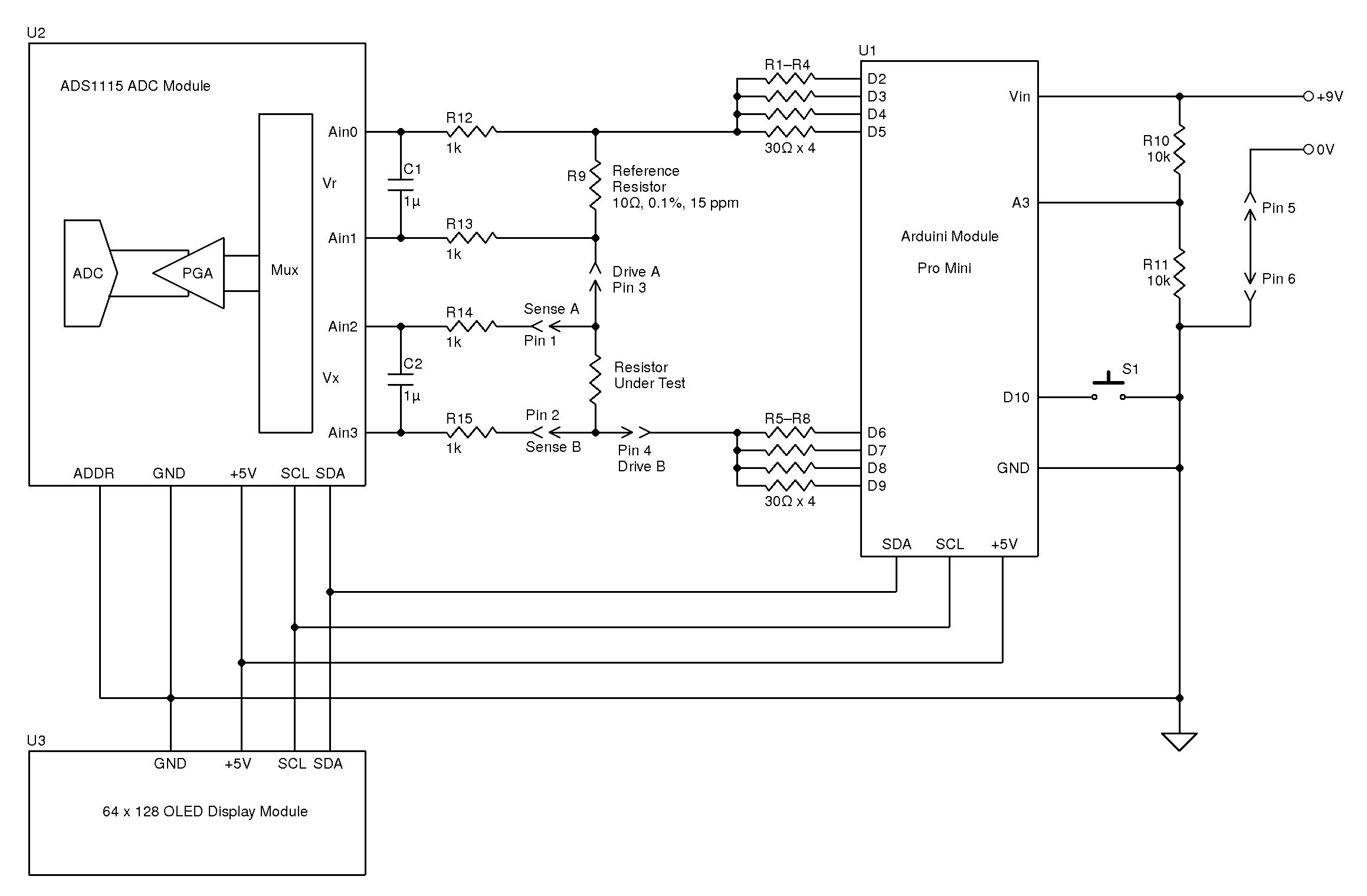
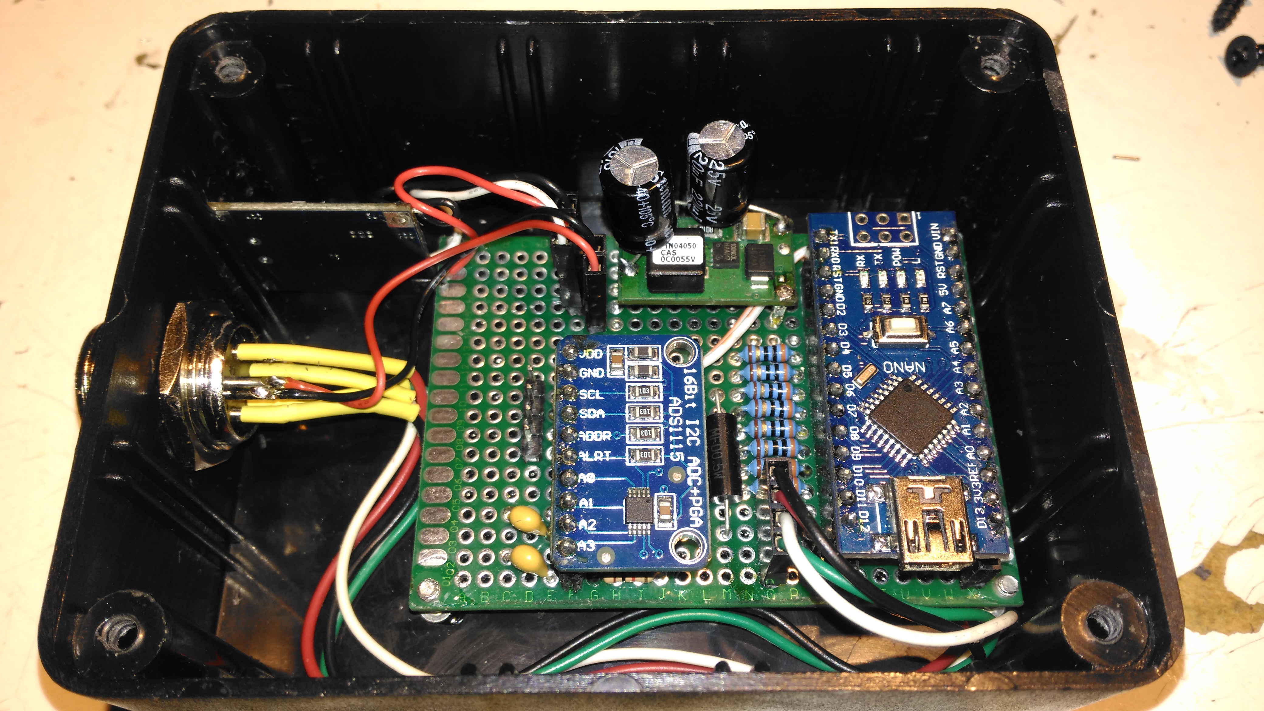
During the rebuild of the wheelchair motors for the support trolley, I found myself needing an accurate milliohm meter to test the armature windings with. Commercial instruments like these are expensive, but some Google searching found a milliohm meter project based around the Arduino from Circuit Cellar.
Circuit Diagram
Here’s the original author’s circuit diagram, paralleling nearly all of the Arduino’s digital output pins together to source/sink the test current, an ADS1115 ADC to take more accurate readings, with the results displayed on a jellybean 128×64 OLED module. The most expensive part here is the 10Ω 0.1% 15ppm reference resistor, R9.
I decided to make some small adjustments to the power supply section of the project, to include a rechargeable lithium cell rather than a 9v PP3 battery. This required some small changes to the Arduino sketch, a DC-DC boost converter to supply 5v from the 3.7v of a lithium cell, a charger module for said cell, and with the battery voltage being within the input range of the analogue inputs, the voltage divider on A3 was removed. A new display icon was also added in to indicate when the battery is being charged, this uses another digital input pin for input voltage sensing.
I also made some basic changes to the way an unreadable resistance is displayed, showing “OL” instead of “—–“, and the meter sends the reading out over the I²C bus, for future expansion purposes. The address the data is directed to is set to 0x50.
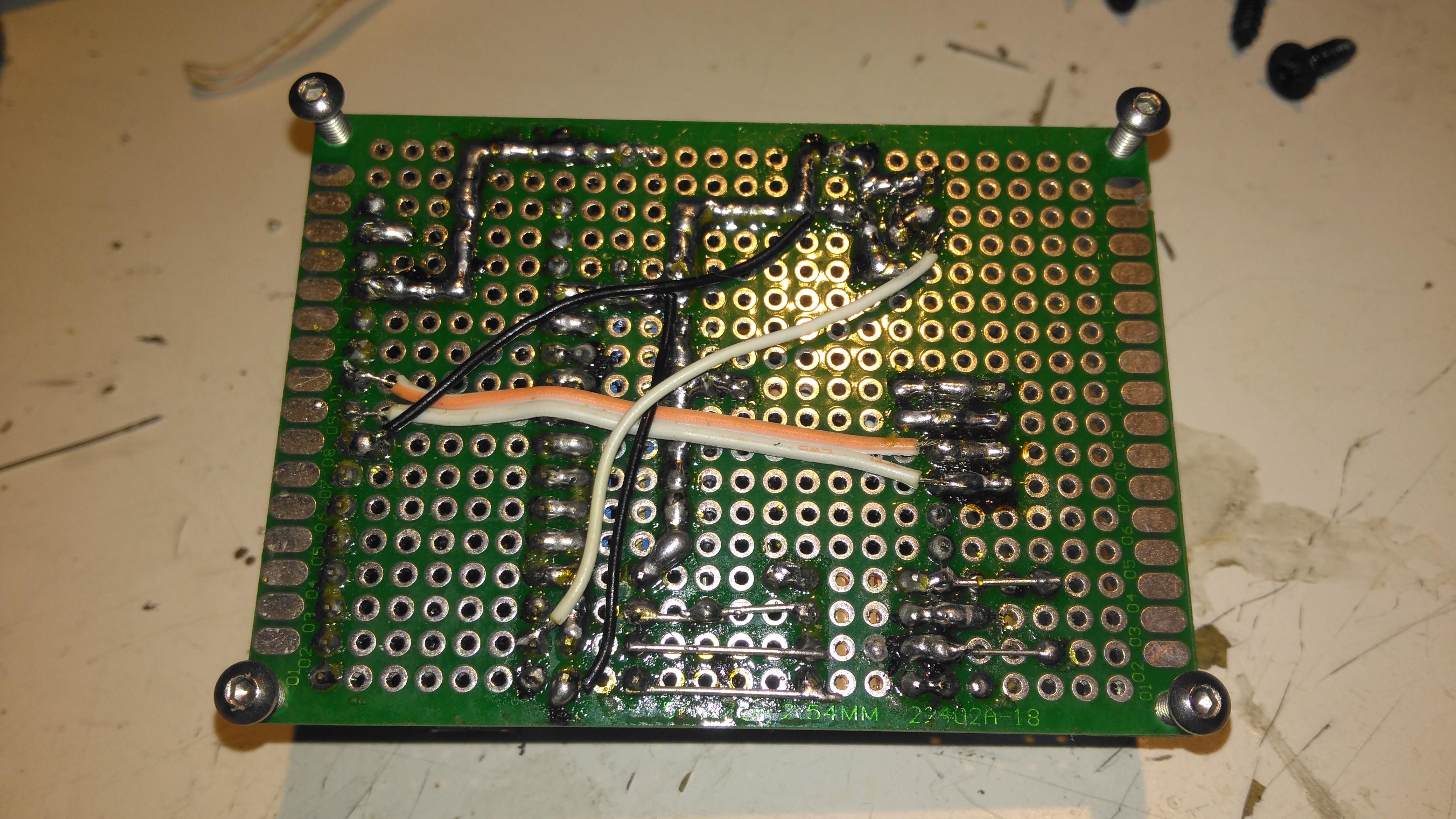
I’ve not etched a PCB for this as I couldn’t be bothered with the messy etchant, so I built this on a matrix board instead.
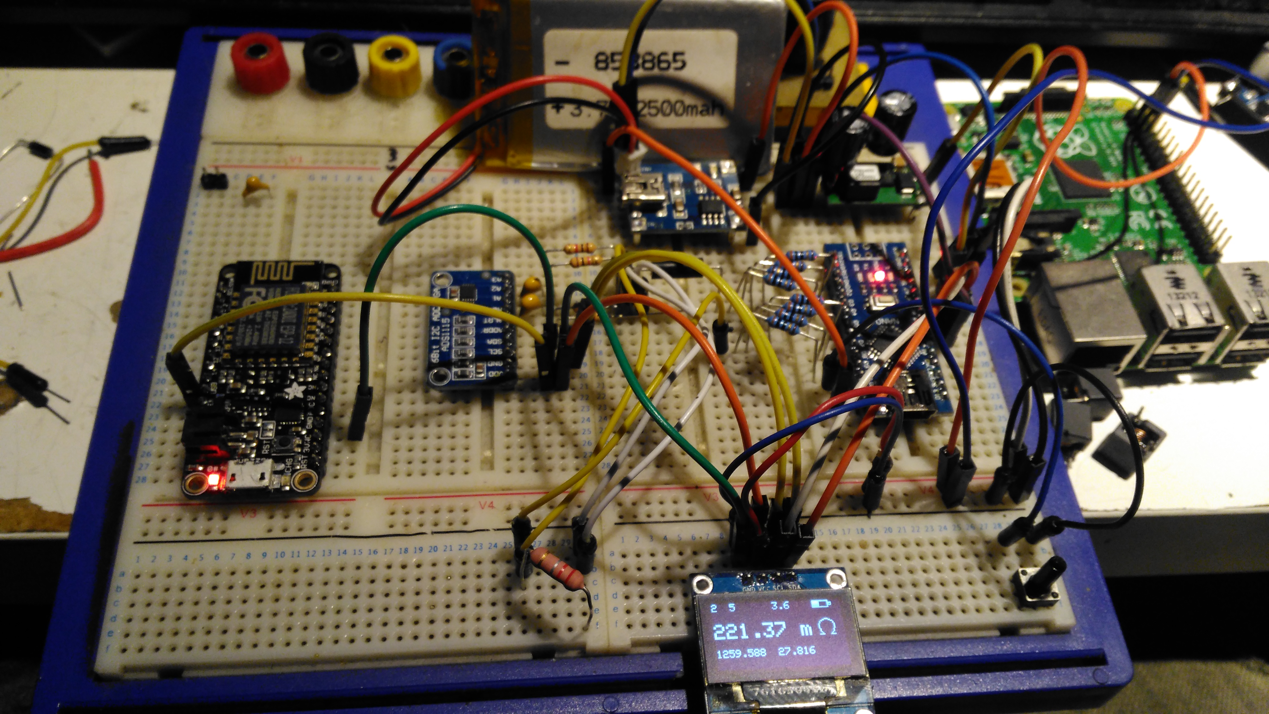
Final Prototype
Since I made some changes to both the software and the hardware components, I decided to prototype the changes on breadboard. The lithium cell is at the top of the image. with the charger module & DC-DC converter. The Arduino Nano is on the right, the ADC & reference resistor on the left, and the display at the bottom.
The Raspberry Pi & ESP8266 module are being used in this case to discharge the battery quicker to make sure the battery level calibration was correct, and to make sure the DC-DC converter would continue to function throughout the battery voltage range.
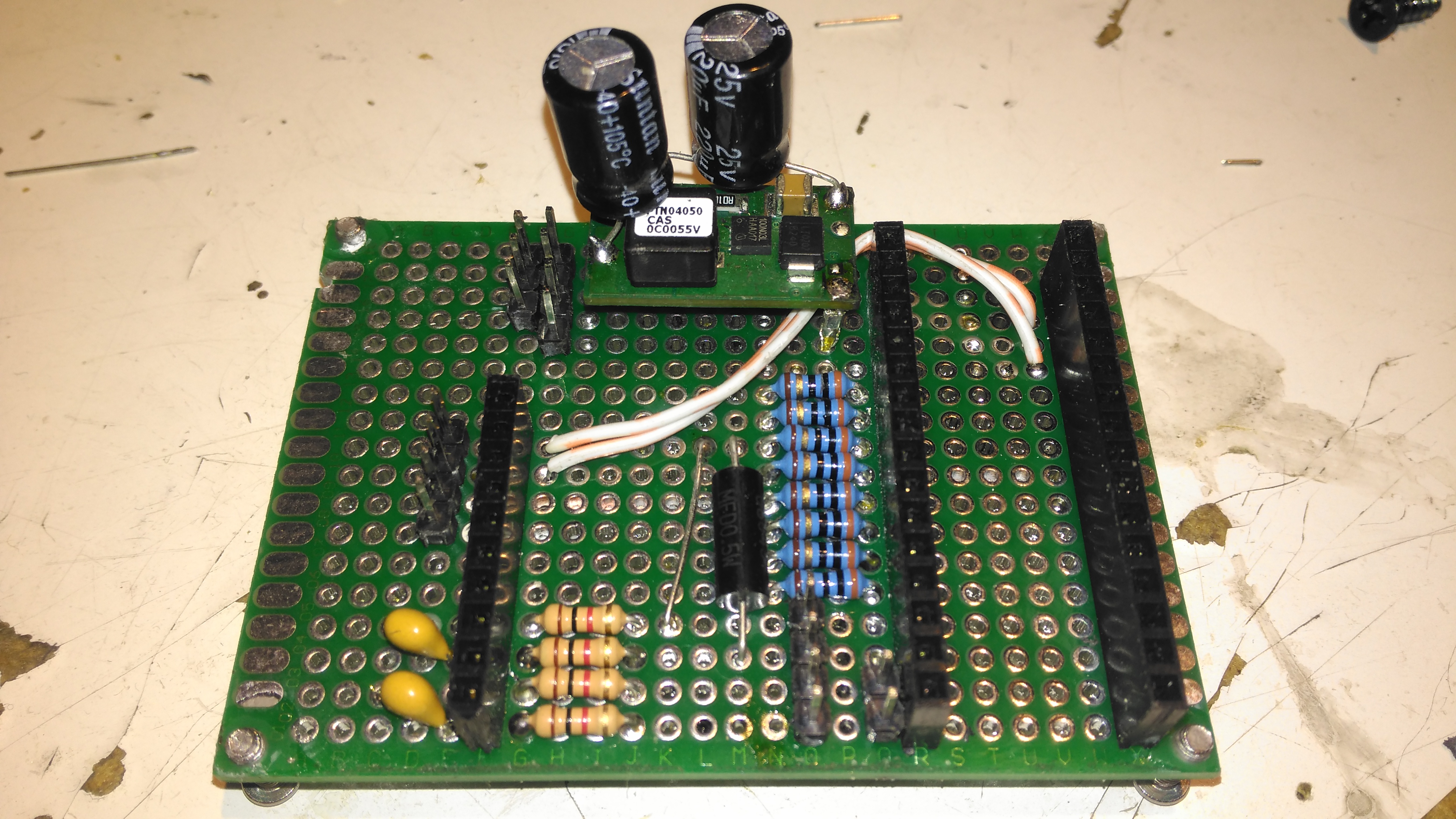
Matrix Board Passives
Here’s the final board with the passive components installed, along with the DC-DC converter. I used a Texas Instruments PTN04050 boost module for power as I had one spare.
Matrix Board Rear
The bottom of the board has most of the wire jumpers for the I²C bus, and power sensing.
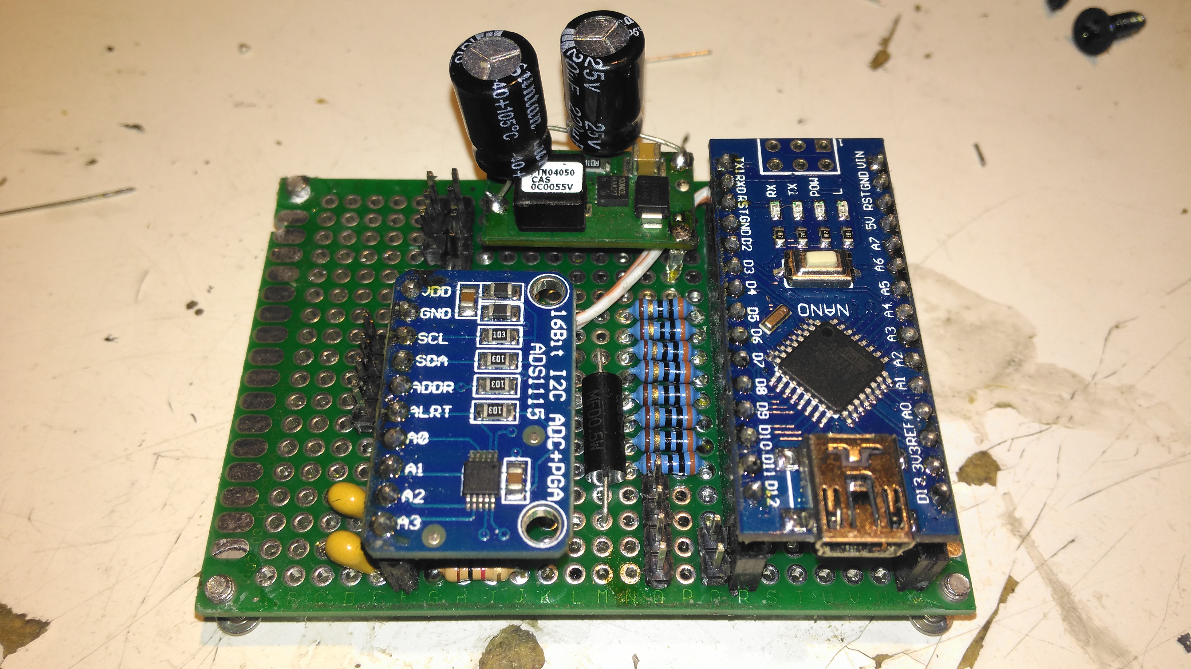
Matrix Board Modules
Here’s both modules installed on the board. I used an Arduino Nano instead of the Arduino Pro Mini that the original used as these were the parts I had in stock. Routing the analogue pins is also easier on the Mini, as they’re brought out to pins in the DIP footprint, instead of requiring wire links to odd spots on the module. To secure the PCB into the case without having to drill any holes, I tapped the corner holes of the matrix board M2.5 & threaded cap head screws in. These are then spot glued to the bottom of the case to secure the finished board.
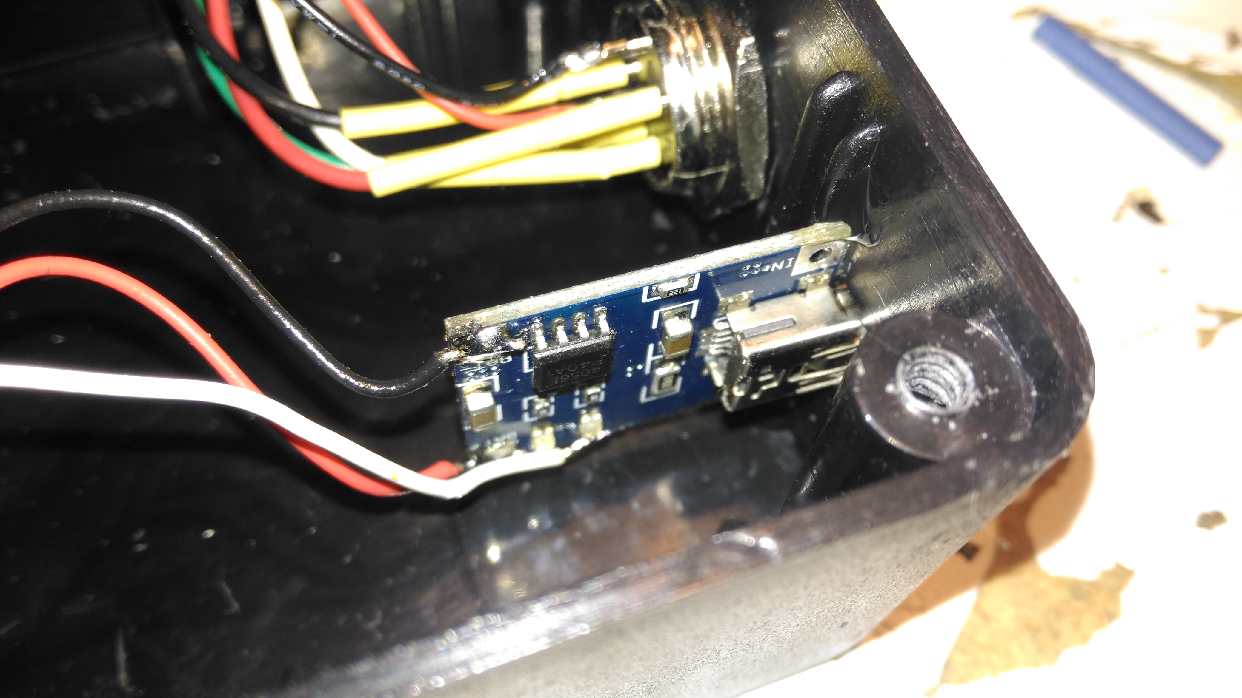
Lithium Charger
The lithium charger module is attached to the side of the enclosure, the third white wire is for input sensing – when the USB cable is plugged in a charge icon is shown on the OLED display.
Input Connections
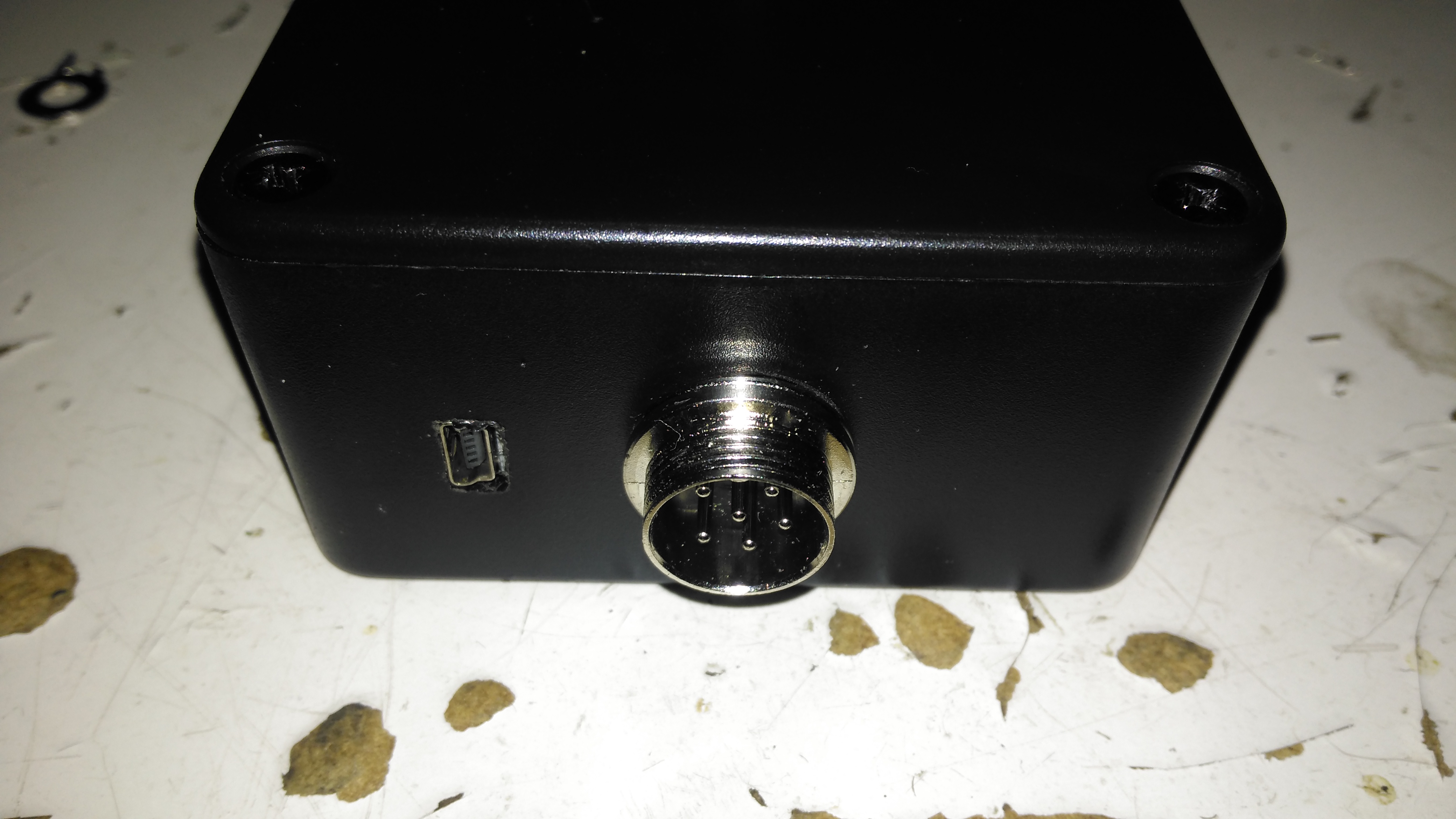
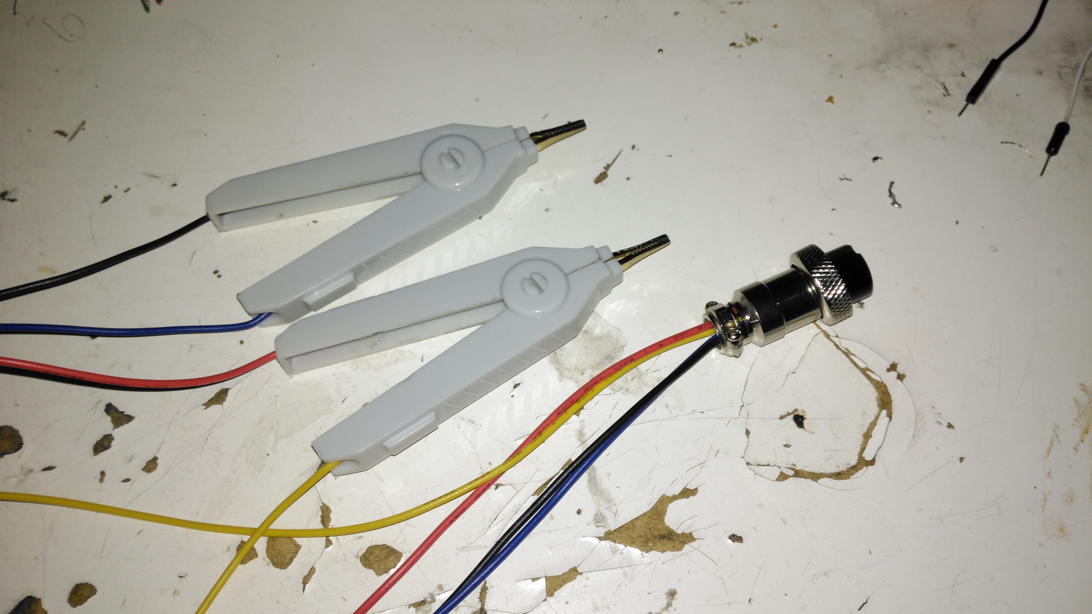
The inputs on the side of the enclosure. I’ve used the same 6-pin round connector for the probes, power is applied to the Arduino when the probes are plugged in.
Module Installed
Everything installed in the enclosure – it’s a pretty tight fit especially with the lithium cell in place.
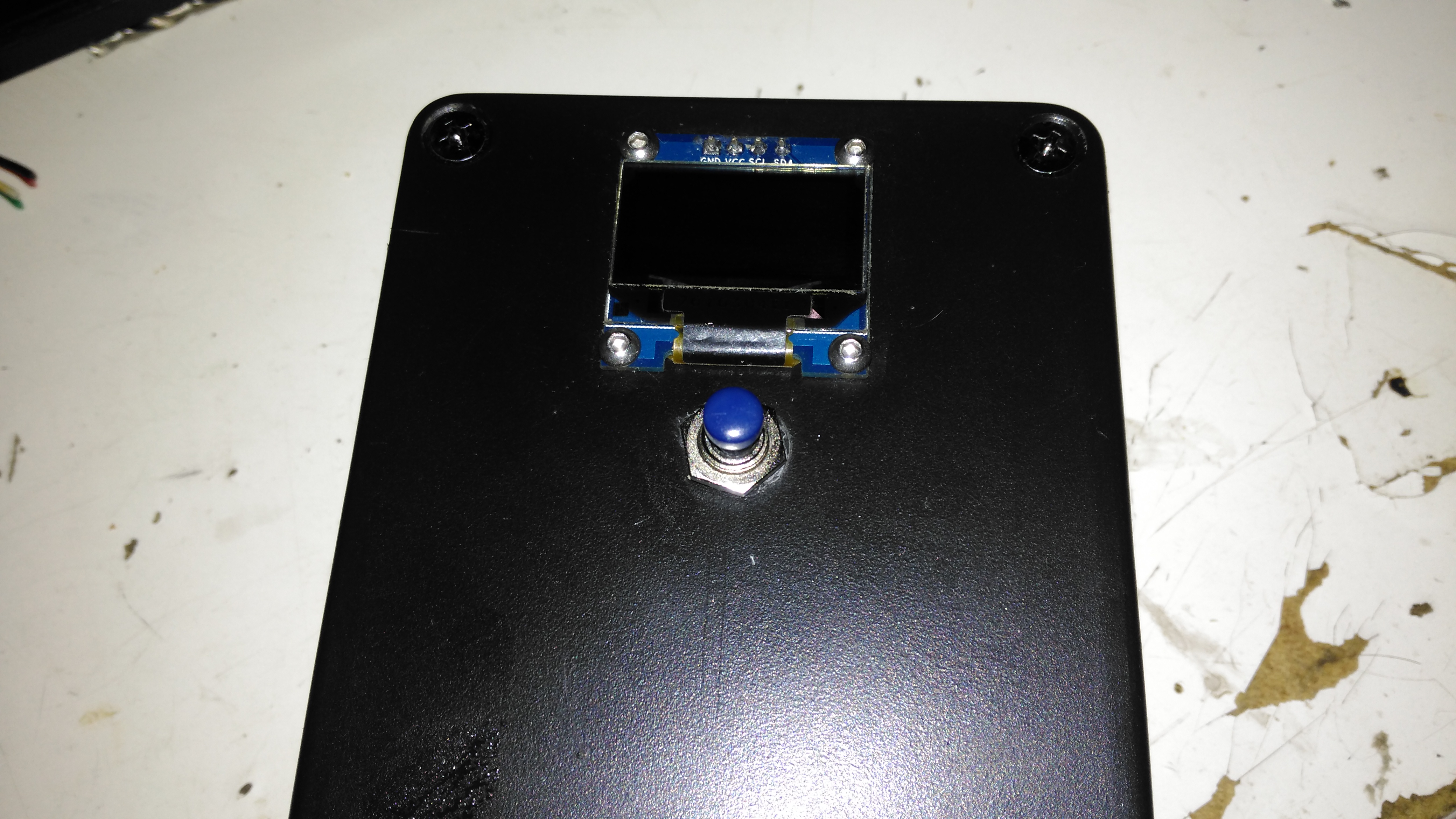
Meter Top Cover
The top cover has the Measure button, and the OLED display panel, the latter secured to the case with M2.5 cap head screws.
Kelvin Clips
Finally, the measurement loom, with Kelvin clips. These were an eBay buy, keeping things cheap. These clips seem to be fairly well built, even if the hinges are plastic. I doubt they’re actually gold-plated, more likely to be brass. I haven’t noticed any error introduced by these cheap clips so far.
The modified sketch is below:
// ---------------------------------------------------------------------------------------------
// Simple, accurate milliohmeter
//
// (c) Mark Driedger 2015
//
// - Determines resistance using 4 wire measurement of voltage across a series connected
// reference resistor (Rr, 10 ohm, 0.1%) and test resistor (Rx)
// - range of accurate measurement is roughly 50 mohm to 10Kohm
// - Uses Arduino digital I/O ports to deliver the test current, alternating polarity to cancel
// offset errors (synchronous detector)
// - 4 I/O pins are used for each leg of the test current to increase test current
// - Averages 2 cycles and 100 samples/cycle
// - Uses a 16 bit ADC ADS1115 with 16x PGA to improve accuracy
//
// Version History
// May 24/15 v1.0-v4.0
// - initial development versions
// May 27/15 v5.0
// - changed display to I2C
// - backed out low power module since it seemed to cause serial port upload problems
// ---------------------------------------------------------------------------------------------
#include <Wire.h>
#include <SPI.h>
#include <Adafruit_GFX.h>
#include <Adafruit_SSD1306.h>
//#include <LowPower.h>
#if (SSD1306_LCDHEIGHT != 64)
#error("Height incorrect, please fix Adafruit_SSD1306.h!");
#endif
// ---------------------------------------------------------------------------------------------
// I/O port usage
// ---------------------------------------------------------------------------------------------
// serial port (debug and s/w download) 0, 1
// I²C interface to ADC & display A4, A5
// positive drive 2, 3, 4, 5
// push to test input 8
// unused 9, 10, 11, A0, A1, A2, A6, A7
// negative drive 6, 7, 8, 9
// battery voltage monitor A3
// debug output 13
#define P_PushToTest 10 // push button (measure), active low
#define P_Debug 13
#define CHG 12
// ADS1115 mux and gain settings
#define ADS1115_CH01 0x00 // p = AIN0, n = AIN1
#define ADS1115_CH03 0x01 // ... etc
#define ADS1115_CH13 0x02
#define ADS1115_CH23 0x03
#define ADS1115_CH0G 0x04 // p = AIN0, n = GND
#define ADS1115_CH1G 0x05 // ... etc
#define ADS1115_CH2G 0x06
#define ADS1115_CH3G 0x07
#define ADS1115_6p144 0x00 // +/- 6.144 V full scale
#define ADS1115_4p096 0x01 // +/- 4.096 V full scale
#define ADS1115_2p048 0x02 // +/- 2.048 V full scale
#define ADS1115_1p024 0x03 // +/- 1.024 V full scale
#define ADS1115_0p512 0x04 // +/- 0.512 V full scale
#define ADS1115_0p256 0x05 // +/- 0.256 V full scale
#define ADS1115_0p256B 0x06 // same as ADS1115_0p256
#define ADS1115_0p256C 0x07 // same as ADS1115_0p256
Adafruit_SSD1306 display(0); // using I2C interface, no reset pin
static int debug_mode = 0; // true in debug mode
float ADS1115read(byte channel, byte gain)
//--------------------------------------------------------------------------------------
// reads a single sample from the ADS1115 ADC at a given mux (channel) and gain setting
// - channel is 3 bit channel number/mux setting (one of ADS1115_CHxx)
// - gain is 3 bit PGA gain setting (one of ADS1115_xpxxx)
// - returns voltage in volts
// - uses single shot mode, polling for conversion complete, default I2C address
// - conversion takes approximatly 9.25 msec
//--------------------------------------------------------------------------------------
{
const int address = 0x48; // ADS1115 I2C address, A0=0, A1=0
byte hiByte, loByte;
int r;
float x;
channel &= 0x07; // constrain to 3 bits
gain &= 0x07;
hiByte = B10000001 | (channel<<4) | (gain<<1); // conversion start command
loByte = B10000011;
Wire.beginTransmission(address); // send conversion start command
Wire.write(0x01); // address the config register
Wire.write(hiByte); // ...and send config register value
Wire.write(loByte);
Wire.endTransmission();
do // loop until conversion complete
{
Wire.requestFrom(address, 2); // config register is still addressed
while(Wire.available())
{
hiByte = Wire.read(); // ... and read config register
loByte = Wire.read();
}
}
while ((hiByte & 0x80)==0); // upper bit (OS) is conversion complete
Wire.beginTransmission(address);
Wire.write(0x00); // address the conversion register
Wire.endTransmission();
Wire.requestFrom(address, 2); // ... and get 2 byte result
while(Wire.available())
{
hiByte = Wire.read();
loByte = Wire.read();
}
r = loByte | hiByte<<8; // convert to 16 bit int
switch(gain) // ... and now convert to volts
{
case ADS1115_6p144: x = r * 6.144 / 32768.0; break;
case ADS1115_4p096: x = r * 4.096 / 32768.0; break;
case ADS1115_2p048: x = r * 2.048 / 32768.0; break;
case ADS1115_1p024: x = r * 1.024 / 32768.0; break;
case ADS1115_0p512: x = r * 0.512 / 32768.0; break;
case ADS1115_0p256:
case ADS1115_0p256B:
case ADS1115_0p256C: x = r * 0.256 / 32768.0; break;
}
return x;
}
// ---------------------------------------------------------------------------------------------
// Drive functions
// - ports 4-7 and A0-A3 are used to differentially drive resistor under test
// - the ports are resistively summed to increase current capability
// - DriveOff() disables the drive, setting the bits to input
// - DriveOn() enables the drive, setting the bits to output
// - DriveP() enables drive with positive current flow (from ports 4-7 to ports A0-A3)
// - DriveN() enables drive with negative current flow
// ---------------------------------------------------------------------------------------------
void DriveP()
{
DriveOff();
digitalWrite( 2, HIGH);
digitalWrite( 3, HIGH);
digitalWrite( 4, HIGH);
digitalWrite( 5, HIGH);
digitalWrite( 6, LOW);
digitalWrite( 7, LOW);
digitalWrite( 8, LOW);
digitalWrite( 9, LOW);
DriveOn();
}
void DriveN()
{
DriveOff();
digitalWrite( 2, LOW);
digitalWrite( 3, LOW);
digitalWrite( 4, LOW);
digitalWrite( 5, LOW);
digitalWrite( 6, HIGH);
digitalWrite( 7, HIGH);
digitalWrite( 8, HIGH);
digitalWrite( 9, HIGH);
DriveOn();
}
void DriveOn()
{
pinMode( 2, OUTPUT); // enable source/sink in pairs
pinMode( 6, OUTPUT);
pinMode( 3, OUTPUT);
pinMode( 7, OUTPUT);
pinMode( 4, OUTPUT);
pinMode( 8, OUTPUT);
pinMode( 5, OUTPUT);
pinMode( 9, OUTPUT);
delayMicroseconds(5000); // 5ms delay
}
void DriveOff()
{
pinMode( 2, INPUT); // disable source/sink in pairs
pinMode( 6, INPUT);
pinMode( 3, INPUT);
pinMode( 7, INPUT);
pinMode( 4, INPUT);
pinMode( 8, INPUT);
pinMode( 5, INPUT);
pinMode( 9, INPUT);
}
int CalcPGA(float x)
// ---------------------------------------------------------------------------------------------
// Calculate optimum PGA setting based on a sample voltage, x, read at lowest PGA gain
// - returns the highest PGA gain that allows x to be read with 10% headroom
// ---------------------------------------------------------------------------------------------
{
x = abs(x);
if (x>3.680) return ADS1115_6p144;
if (x>1.840) return ADS1115_4p096;
if (x>0.920) return ADS1115_2p048;
if (x>0.460) return ADS1115_1p024;
if (x>0.230) return ADS1115_0p512;
else return ADS1115_0p256;
}
void BatteryIcon(float charge)
// ---------------------------------------------------------------------------------------------
// Draw a battery charge icon into the display buffer without refreshing the display
// - charge ranges from 0.0 (empty) to 1.0 (full)
// ---------------------------------------------------------------------------------------------
{
static const unsigned char PROGMEM chg[] = // Battery Charge Icon
{ 0x1c, 0x18, 0x38, 0x3c, 0x18, 0x10, 0x20, 0x00 };
int w = constrain(charge, 0.0, 1.0)*16; // 0 to 16 pixels wide depending on charge
display.drawRect(100, 0, 16, 7, WHITE); // outline
display.drawRect(116, 2, 3, 3, WHITE); // nib
display.fillRect(100, 0, w, 7, WHITE); // charge indication
//battery charging indication
pinMode(CHG, INPUT);
if (digitalRead(CHG) == HIGH)
display.drawBitmap(91, 0, chg, 8, 8, WHITE);
}
void f2str(float x, int N, char *c)
// ---------------------------------------------------------------------------------------------
// Converts a floating point number x to a string c with N digits of precision
// - *c must be a string array of length at least N+3 (N + '-', '.', '\0')
// - x must be have than N leading digits (before decimal) or "#\0" is returned
// ---------------------------------------------------------------------------------------------
{
int j, k, r;
float y;
if (x<0.0) // handle negative numbers
{
*c++ = '-';
x = -x;
}
for (j=0; x>=1.0; j++) // j digits before decimal point
x /= 10.0; // .. and scale x to be < 1.0
if (j>N) // return error string if too many digits
{
*c++ = '#';
*c++ = '\0';
return;
}
y = pow(10, (float) N); // round to N digits
x = round(x * y) / y;
if (x>1.0) // if 1st digit rounded up ...
{
x /= 10.0; // then normalize back down 1 digit
j++;
}
for (k=0; k<N; k++)
{
r = (int) (x*10.0); // leading digit as int
x = x*10-r; // remove leading digit and shift 1 digit
*c++ = r + '0'; // add leading digit to string
if (k==j-1 && k!=N-1) // add decimal point after j digits
*c++ = '.'; // ... unless there are N digits before decimal
}
*c++ = '\0';
}
void DisplayResistance(float x)
// ---------------------------------------------------------------------------------------------
// Adds the resistance value, x, to the display buffer without refreshing the display
// - converts to kohm, milliohm or microohm if necessary
// ---------------------------------------------------------------------------------------------
{
static const unsigned char PROGMEM omega_bmp[] = // omega (ohm) symbol
{ B00000011, B11000000,
B00001100, B00110000,
B00110000, B00001100,
B01000000, B00000010,
B01000000, B00000010,
B10000000, B00000001,
B10000000, B00000001,
B10000000, B00000001,
B10000000, B00000001,
B10000000, B00000001,
B01000000, B00000010,
B01000000, B00000010,
B01000000, B00000010,
B00100000, B00000100,
B00010000, B00001000,
B11111000, B00011111 };
char s[8];
char prefix;
if (x>=1000.0) // display in killo ohms
{
x /= 1000.0;
prefix = 'k';
}
else if (x<0.001) // display in micro ohms
{
x *= 1000000.0;
prefix = 0xe5; // mu
}
else if (x<1.0) // display in milli ohms
{
x *= 1000.0;
prefix = 'm';
}
else
prefix = ' '; // display in ohms
f2str(x, 5, s);
// display computed resistance
display.setTextSize(2);
display.setTextColor(WHITE);
display.setCursor(0,20);
display.print(s);
// display prefix
display.setCursor(85,20);
display.print(prefix);
// display omega (ohms) symbol
display.drawBitmap(103, 18, omega_bmp, 16, 16, WHITE);
}
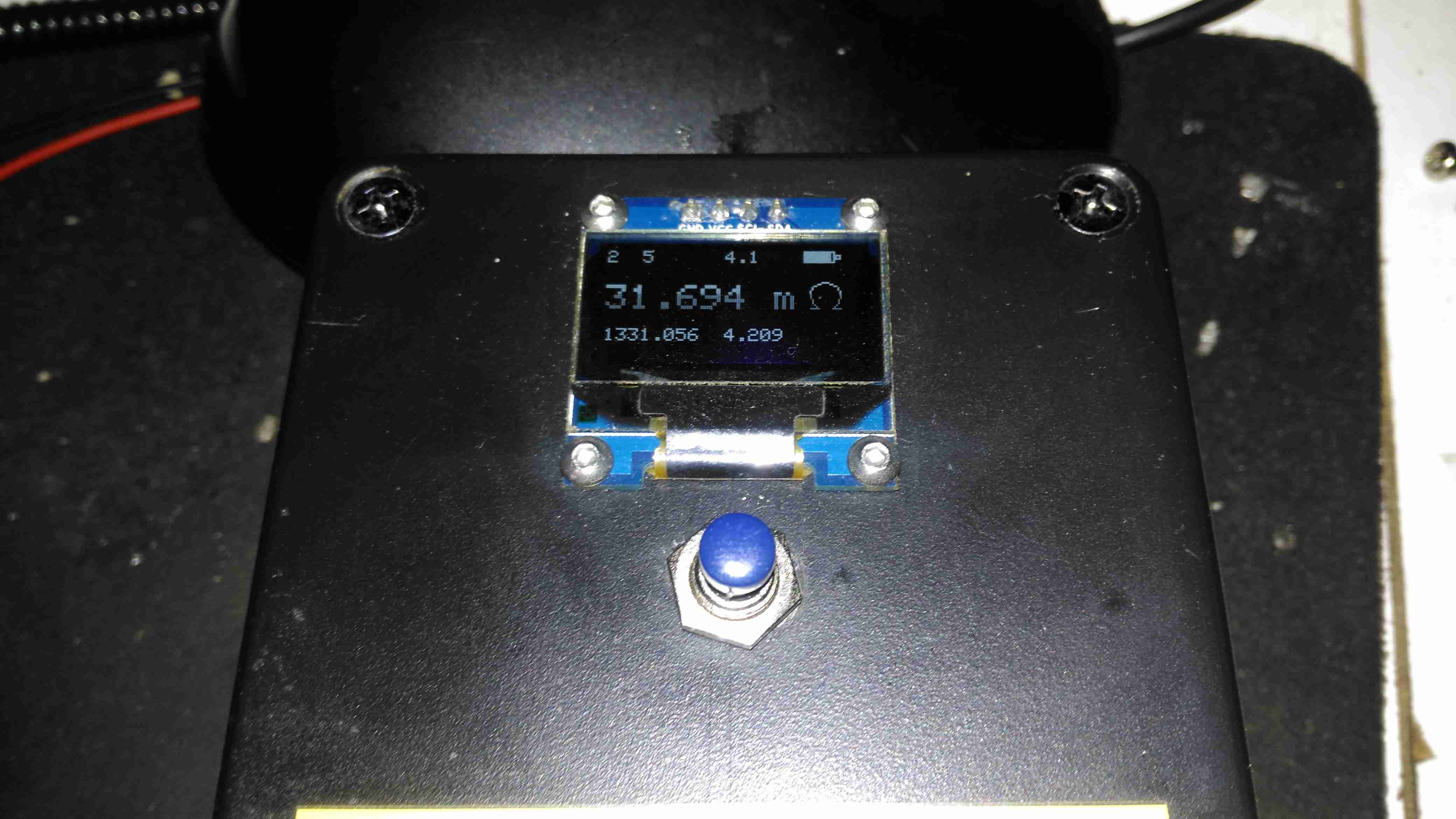
void DisplayDebug(int a, int b, float x, float y, float Vbat)
// ---------------------------------------------------------------------------------------------
// Adds debug info to the display buffer without showing the updated display
// - Adds 2 ints (a, b) and a float(Vbat) to the top line and 2 floats (x, y)
// to the bottom line+, all in small (size 1) text
// ---------------------------------------------------------------------------------------------
{
// display x, y in lower left, small font
display.setTextSize(1);
display.setCursor(0,45);
display.print(x,3);
display.print(" ");
display.print(y,3);
// display a, b in upper left, small font
display.setTextSize(1);
display.setCursor(0,0);
display.print(a);
display.print(" ");
display.print(b);
// display Vbat in upper middle, small font
display.setTextSize(1);
display.setCursor(60,0);
display.print(Vbat,1);
}
void DisplayStr(char *s)
// ---------------------------------------------------------------------------------------------
// Adds a string, s, to the display buffer without refreshing the display @ (0,20)
// ---------------------------------------------------------------------------------------------
{
display.setTextSize(2);
display.setTextColor(WHITE);
display.setCursor(8,20);
display.print(s);
}
#ifdef TESTMODE
void loop()
{
while (digitalRead(P_PushToTest))
;
DriveP();
display.clearDisplay();
DisplayStr("Drive: +");
display.display();
delay(250);
while (digitalRead(P_PushToTest))
;
DriveN();
display.clearDisplay();
DisplayStr("Drive: -");
display.display();
delay(250);
while (digitalRead(P_PushToTest))
;
DriveOff();
display.clearDisplay();
DisplayStr("Drive: Off");
display.display();
delay(250);
}
#endif
void setup()
// ---------------------------------------------------------------------------------------------
// - initializae display and I/O ports
// ---------------------------------------------------------------------------------------------
{
DriveOff(); // disable current drive
Wire.begin(); // join I2C bus
display.begin(SSD1306_SWITCHCAPVCC, 0x3c, 0); // initialize display @ address 0x3c, no reset
pinMode(P_PushToTest, INPUT_PULLUP); // measure push button switch, active low
debug_mode = !digitalRead(P_PushToTest); // if pushed during power on, then debug mode
pinMode(P_Debug, OUTPUT); // debug port
}
void loop()
// ---------------------------------------------------------------------------------------------
// main measurement loop
// ---------------------------------------------------------------------------------------------
{
const float Rr = 10.0; // reference resistor value, ohms
const float Rcal = 1.002419; // calibration factor
const int N = 2; // number of cycles to average
const int M = 50; // samples per half cycle
static long Toff;
double Rx; // calculated resistor under test, ohms
byte PGAr, PGAx; // PGA gains (r = reference, x = test resistors)
float Vr, Vx, Wx, Wr; // voltages in V
float Rn; // calculated resistor under test, ohms, single sample
double Avgr, Avgx; // average ADC readings in mV
int j, k, n;
float Vbat; // battery voltage in V (from 2:1 divider)
char serialbuff[10]; // Buffer for sending the reading over I²C
display.clearDisplay();
DisplayStr("measuring");
display.display();
// determine PGA gains
DriveP();
Wr = ADS1115read(ADS1115_CH01, ADS1115_6p144);
Wx = ADS1115read(ADS1115_CH23, ADS1115_6p144);
DriveN();
Vr = -ADS1115read(ADS1115_CH01, ADS1115_6p144);
Vx = -ADS1115read(ADS1115_CH23, ADS1115_6p144);
// measure battery voltage ... while drive is on so there is a load
Vbat = analogRead(A3)*5.0/1024.0; // 2:1 divider (5V FS) on 4.2v lithium battery
DriveOff();
PGAr = CalcPGA(max(Vr, Wr)); // determine optimum PGA gains
PGAx = CalcPGA(max(Vx, Wx));
// measure resistance using synchronous detection
Avgr = Avgx = 0.0; // clear averages
Rx = 0.0;
n = 0;
for (j=0; j<N; j++) // for each cycle
{
DriveP(); // turn on drive, positive
for (k=0; k<M; k++)
{
digitalWrite(P_Debug, 1);
Vx = ADS1115read(ADS1115_CH23, PGAx);
digitalWrite(P_Debug, 0);
Vr = ADS1115read(ADS1115_CH01, PGAr);
Avgx += Vx;
Avgr += Vr;
Rn = Vx/Vr;
if (Rn>0.0 && Rn<10000.0)
{
Rx += Rn;
n++;
}
}
DriveN(); // turn on drive, negative
for (k=0; k<M; k++)
{
digitalWrite(P_Debug, 1);
Vx = ADS1115read(ADS1115_CH23, PGAx);
digitalWrite(P_Debug, 0);
Vr = ADS1115read(ADS1115_CH01, PGAr);
Avgx -= Vx;
Avgr -= Vr;
Rn = Vx/Vr;
if (Rn>0.0 && Rn<10000.0)
{
Rx += Rn;
n++;
}
}
}
DriveOff();
Rx *= Rr * Rcal / n; // apply calibration factor and compute average
Avgr *= 1000.0 / (2.0*N*M); // average in mV
Avgx *= 1000.0 / (2.0*N*M);
// display the results ... battery icon, Rx measurement, debug info if requested
display.clearDisplay(); // ... and display result
BatteryIcon((Vbat-3.0)/(4.2-3.0)); // 7.5V = 0%, 9V = 100%
//display.drawLine(0, 8, 127, 8, WHITE); //Draw separator line under icons
if (n==0){ // no measurement taken ...
display.setTextSize(2);
display.setCursor(51,20);
display.print(F("OL"));
}
//DisplayStr("-----");
else
DisplayResistance(Rx);
//Send Reading via I²C
Wire.beginTransmission(0x50);
Wire.write(dtostrf(Rx, 5, 5, serialbuff));
Wire.endTransmission();
if (debug_mode)
DisplayDebug(PGAr, PGAx, Avgr, Avgx, Vbat);
display.display(); // show the display
// and then wait for next measurement request
Toff = millis()+60000L;
while(digitalRead(P_PushToTest)) // loop until measure button pressed
{
// Enter power down state for 120ms with ADC and BOD module disabled
//LowPower.powerDown(SLEEP_120MS, ADC_OFF, BOD_OFF);
if (millis()>Toff) // after 7 seconds ...
{
display.clearDisplay(); // clear display
display.display();
}
}
}
Time for another eBay special: this time it’s an 8-port video distribution amplifier, with BNC connections designed for commercial/industrial equipment. Not much on the front panel above, apart from the power switch & LED.
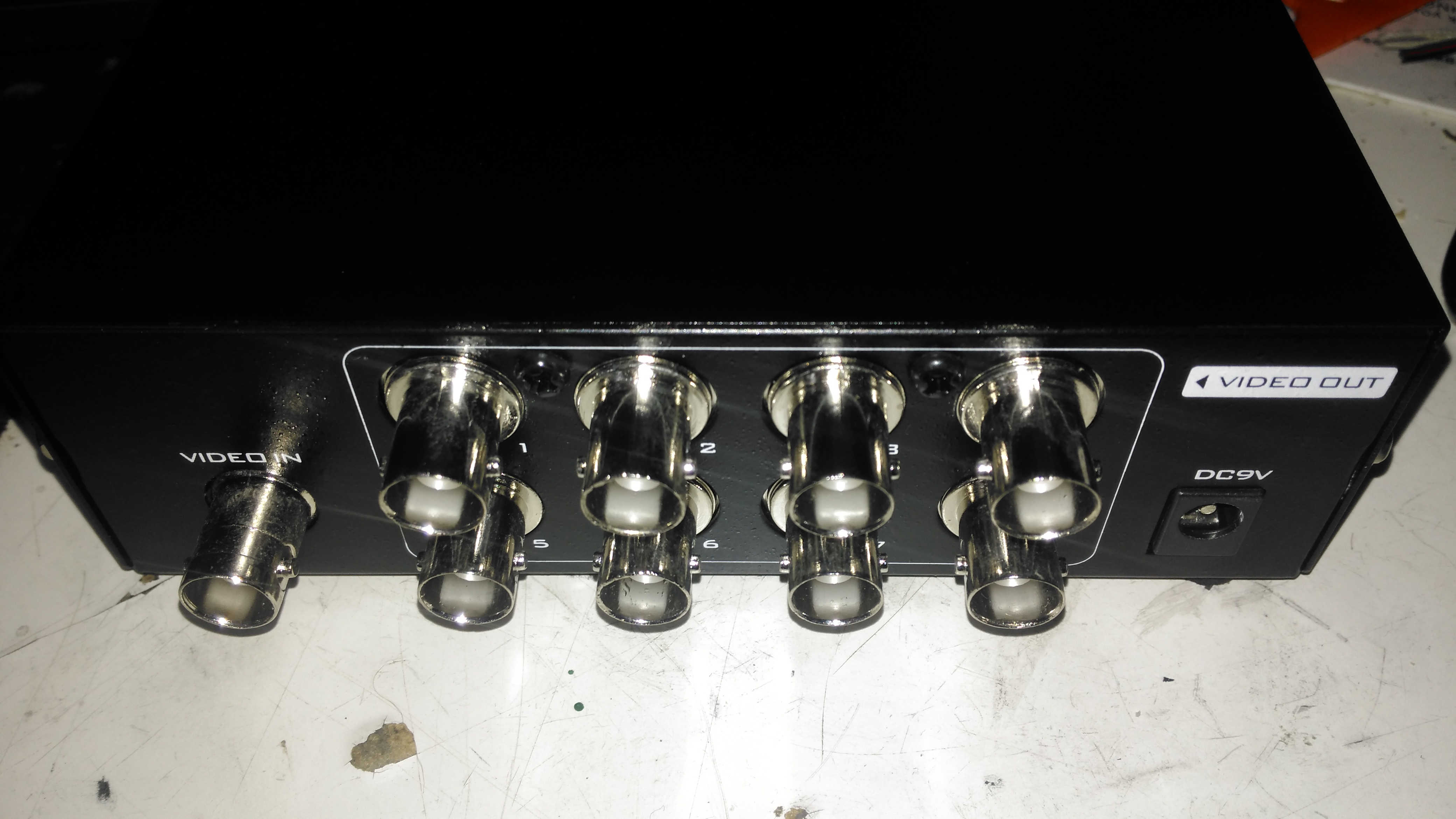
Rear Panel
The rear panel has all the connectors, input is on the left, while the outputs are in the centre. Power is supplied through the barrel jack on the right, 9v DC in this case.
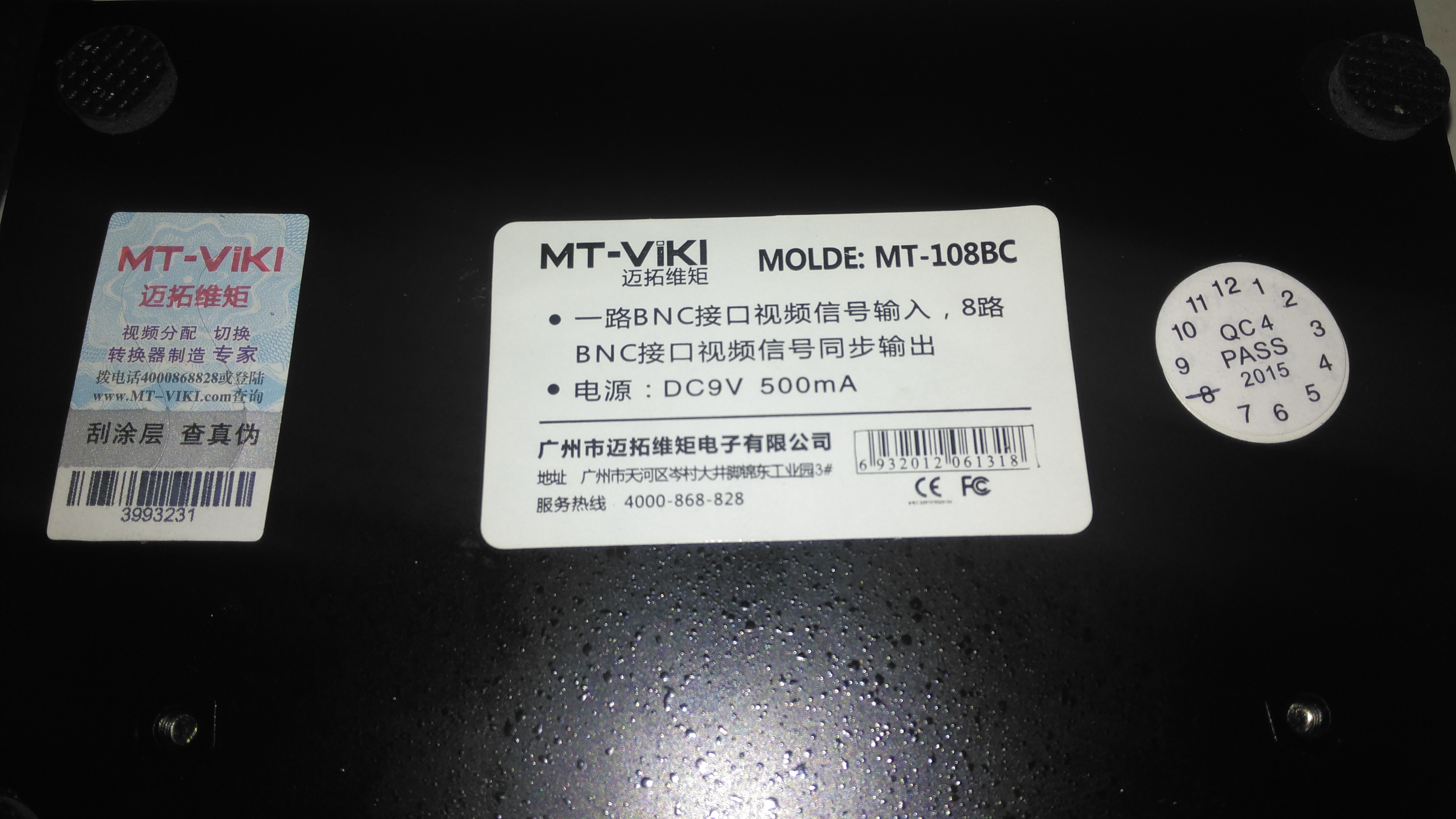
Data Label
Not much in English on the data labels, there’s also an authenticity label on the left to make sure you don’t get a fake.
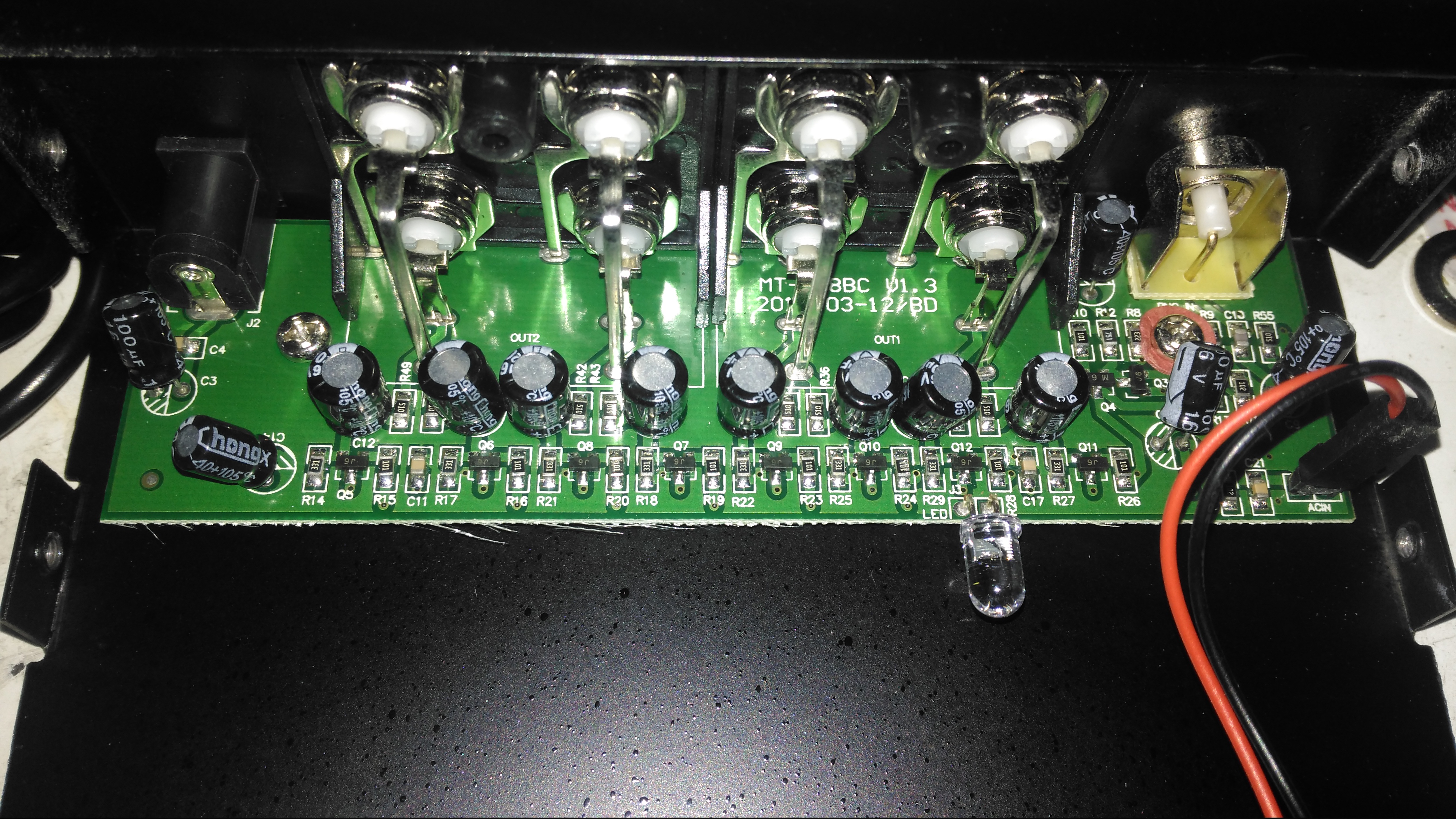
Amplifier Board
Taking the lid off reveals a very small PCB, taking up less than a third of the aluminium case! The input stage is on the right, composed of a pair of SOT-23 transistors to buffer the incoming signal. There’s an KST812M6 PNP & an S9014 NPN Epitaxial. The signal is then fed to the output stages, all individual S9014 NPN transistors to the output ports.
The power LED is just poking in the general direction of the hole in the front panel, so this isn’t likely to work very well – it’s going to illuminate the inside of the case more!
A few months ago I did a teardown on this Anker PowerPort Speed 5 USB charger, but I didn’t get round to detailing the conversion to 12v I had to do, so I’ll get to that now I’ve got a couple more to convert over.
Power Module
Here’s the internals of the Anker charger once I’ve removed the casing – which like many things these days, is glued together. (Joints can be cracked with a screwdriver handle without damaging the case). There’s lots of heatsinking in here to cool the primary side switching devices & the pot core transformers, so this is the first thing to get removed.
Heatsink Removed
Once the heatsink has been removed, the pot core transformers are visible, wrapped in yellow tape. There’s some more heatsink pads & thermal grease here, to conduct heat better. The transformers, primary side switching components & input filter capacitor have to go.
Primary Side Components Removed
Here’s the PCB once all the now redundant mains conversion components have been deleted. I’ve left the input filtering & bridge rectifier in place, as this solves the issue of the figure-8 cable on the input being reversible, polarity of the input doesn’t matter with the bridge. I’ve removed the main filter capacitor to make enough room for the DC-DC converters to be fitted.
Tails Installed
Installing the tails to connect everything together is the next step, this charger requires two power supplies – the QC3 circuits need 14.4v to supply the multi-voltage modules, the remaining 3 standard ports require 5v. The DC input tails are soldered into place where the main filter capacitor was, while the outputs are fitted to the spot the transformer secondary windings ended up. I’ve left the factory Schottky rectifiers in place on the secondary side to make things a little more simple, the output voltages of both the DC-DC converters does need to be increased slightly to compensate for the diode drops though. I’ve also bypassed the mains input fuse, as at 12v the input current is going to be substantially higher than when used on mains voltage.
DC-DC Converters Installed
With a squeeze both the boost converter & the buck converter fit into place on the PCB.
Since I’ve discovered some nice high power PSUs in the form of Playstation 3 PSUs, it’s time to get a new Bench PSU Build underway!
Specifications
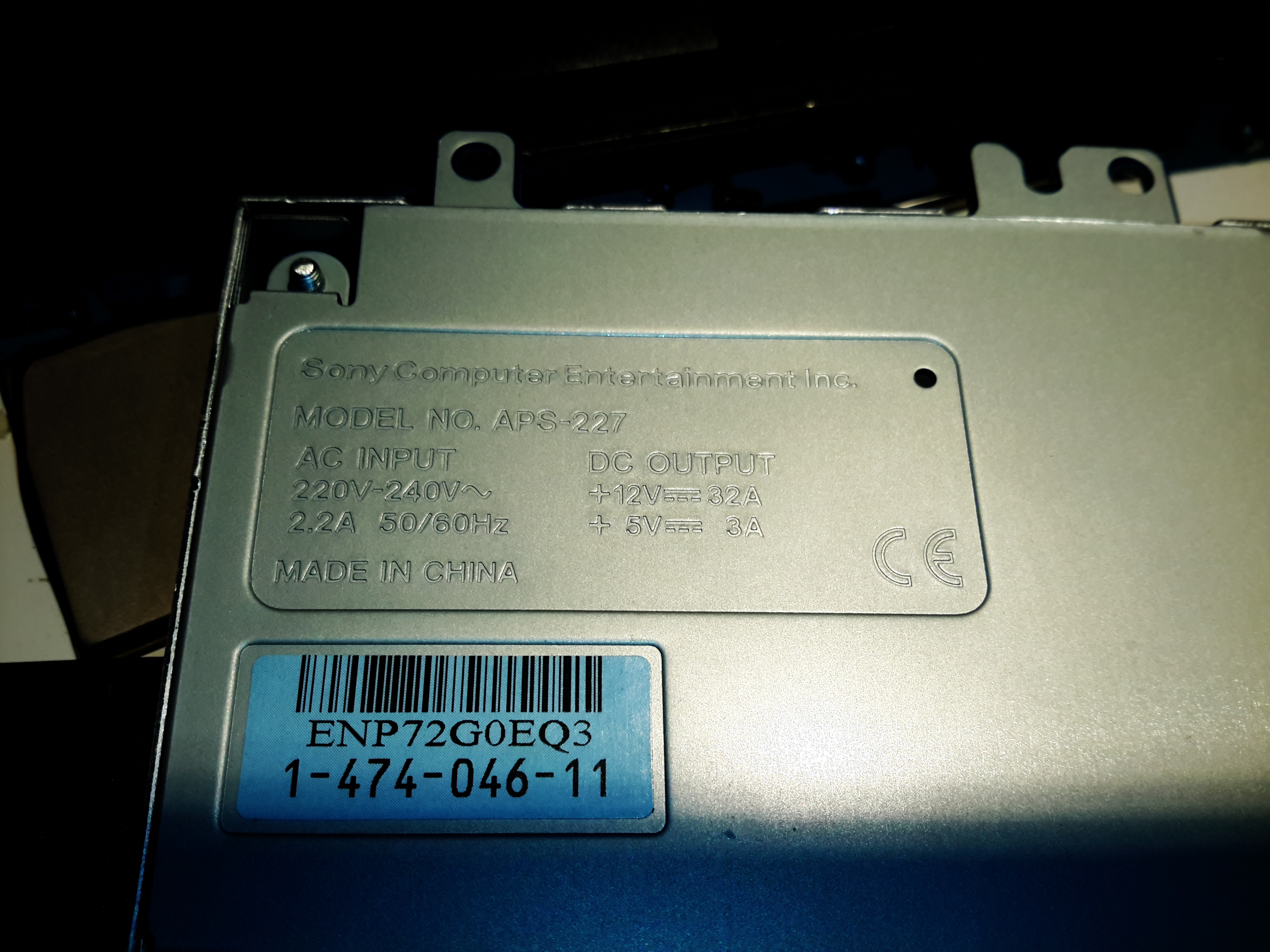
I’ve gone for the APS-227 version as it’s got the 32A rail. This makes things slightly beefier overall, as the loading will never be anywhere close to 100% for long, more headroom on the specs is the result.
Desktop Instrument Case
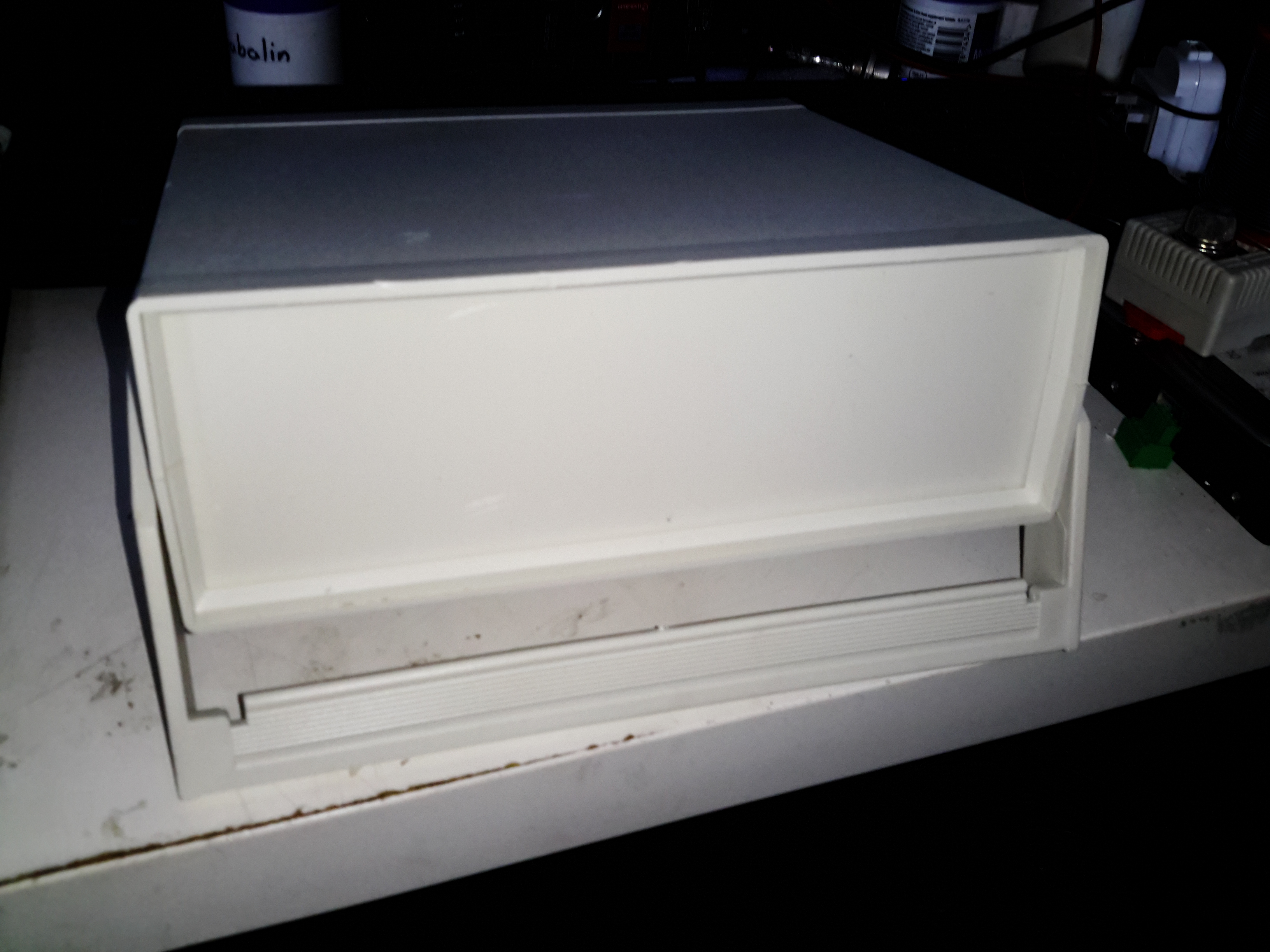
The case I’ve chosen for this is an ABS desktop instrument case from eBay, the TE554 200x175x70mm. The ABS is easy to cut the holes for all the through-panel gear, along with being sturdy enough. Aluminium front & back panels would be a nice addition for a better look.
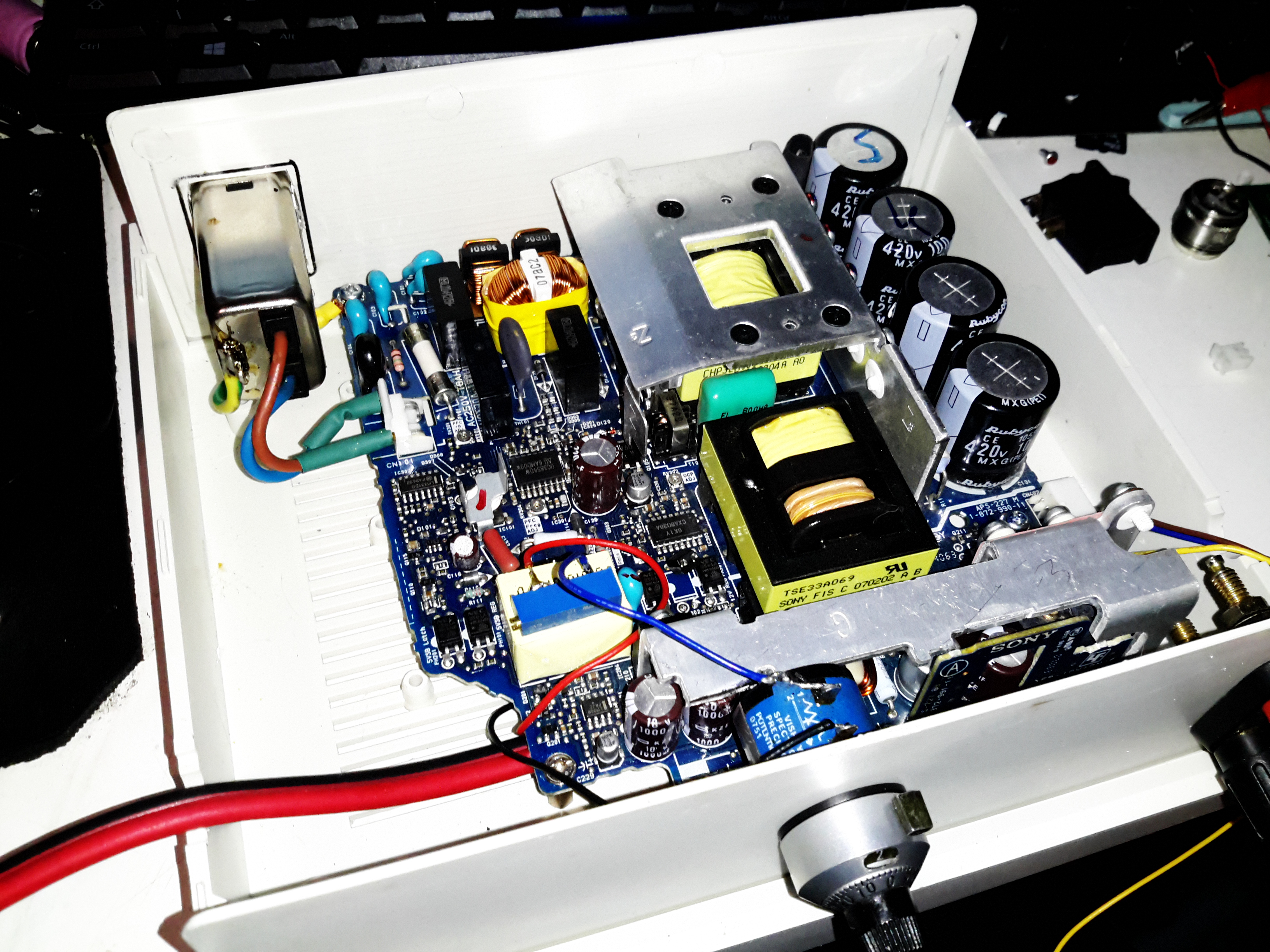
PSU Mounted
The PSU board is removed from it’s factory casing & installed on the bottom shell half, unfortunately the moulded-in posts didn’t match the screw hole locations so I had to mount some brass standoffs separately. The AC input is also fitted here, I’ve used a common-mode filter to test things (this won’t be staying, as it fouls one of the case screw holes). The 40A rated DC output cable is soldered directly to the PCB traces, as there’s no room under the board to fit the factory DC power connector. (This is the biggest case I could find on eBay, and things are still a little tight). Some minor modifications were required to get the PCB to fit correctly.
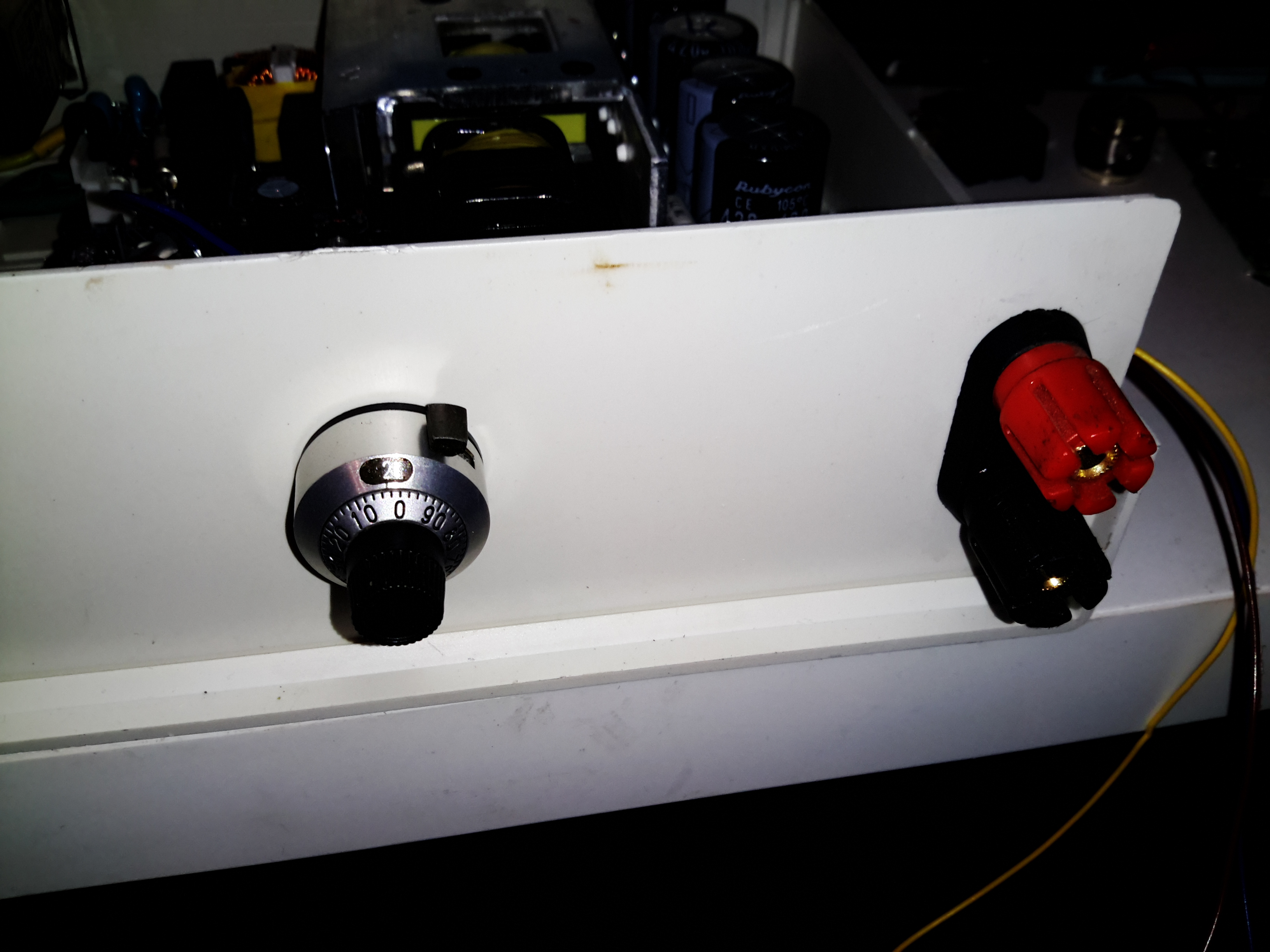
Output Terminals & Adjuster
I decided to add some limited voltage adjustment capability to the front panel, I had a 100Ω Vishay Spectrol Precision 10-turn potentiometer in my parts bin, from a project long since gone that just about fits between the panel & the output rectifier heatsink. The trimpot I added when I first posted about these PSUs is now used to set the upper voltage limit of 15 volts. (The output electrolytics are 16v rated, and are in an awkward place to get at to change for higher voltage parts). The binding posts are rated to 30A, and were also left over from a previous project.
Vishay Spectrol 10-Turn
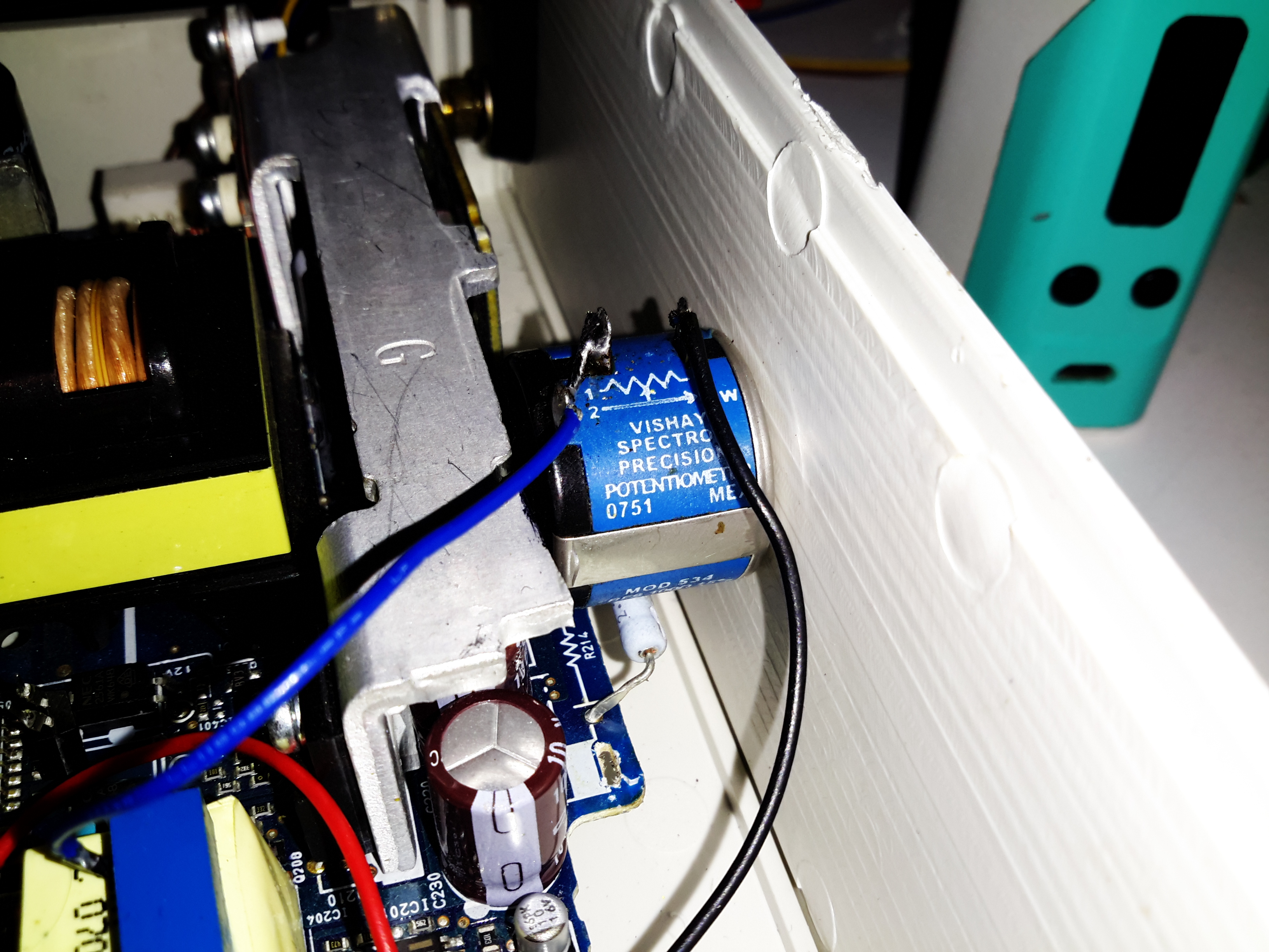
Addon Regulator Components
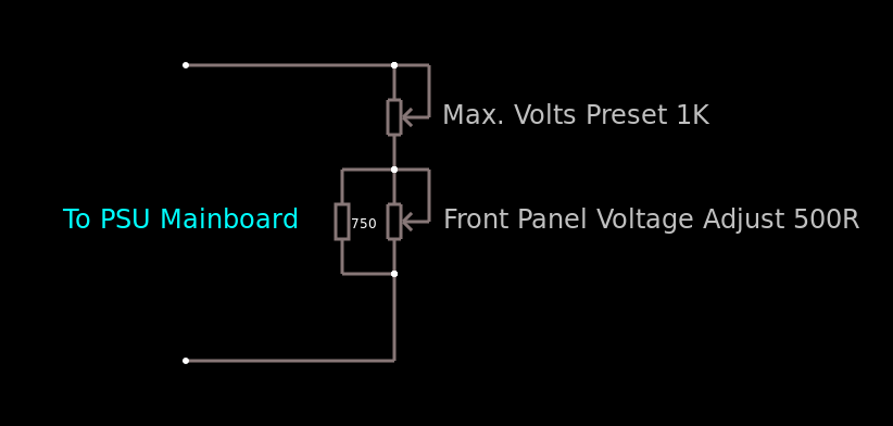
This front panel potentiometer is electrically in series with the trimpot glued to the top of the auxiliary transformer, see above for a simple schematic of the added components. In this PSU, reducing the total resistance in the regulator circuit increases the voltage, so make sure the potentiometer is wired correctly for this!
After some experimentation, a 500Ω 10-turn potentiometer would be a better match, with a 750Ω resistor in parallel to give a total resistance range on the front panel pot of 300Ω. This will give a lower minimum voltage limit of about 12.00v to make lead-acid battery charging easier.
I’ve had to make a minor modification to the output rectifier heatsink to get this pot to fit in the available space, but nothing big enough to stop the heatsink working correctly.
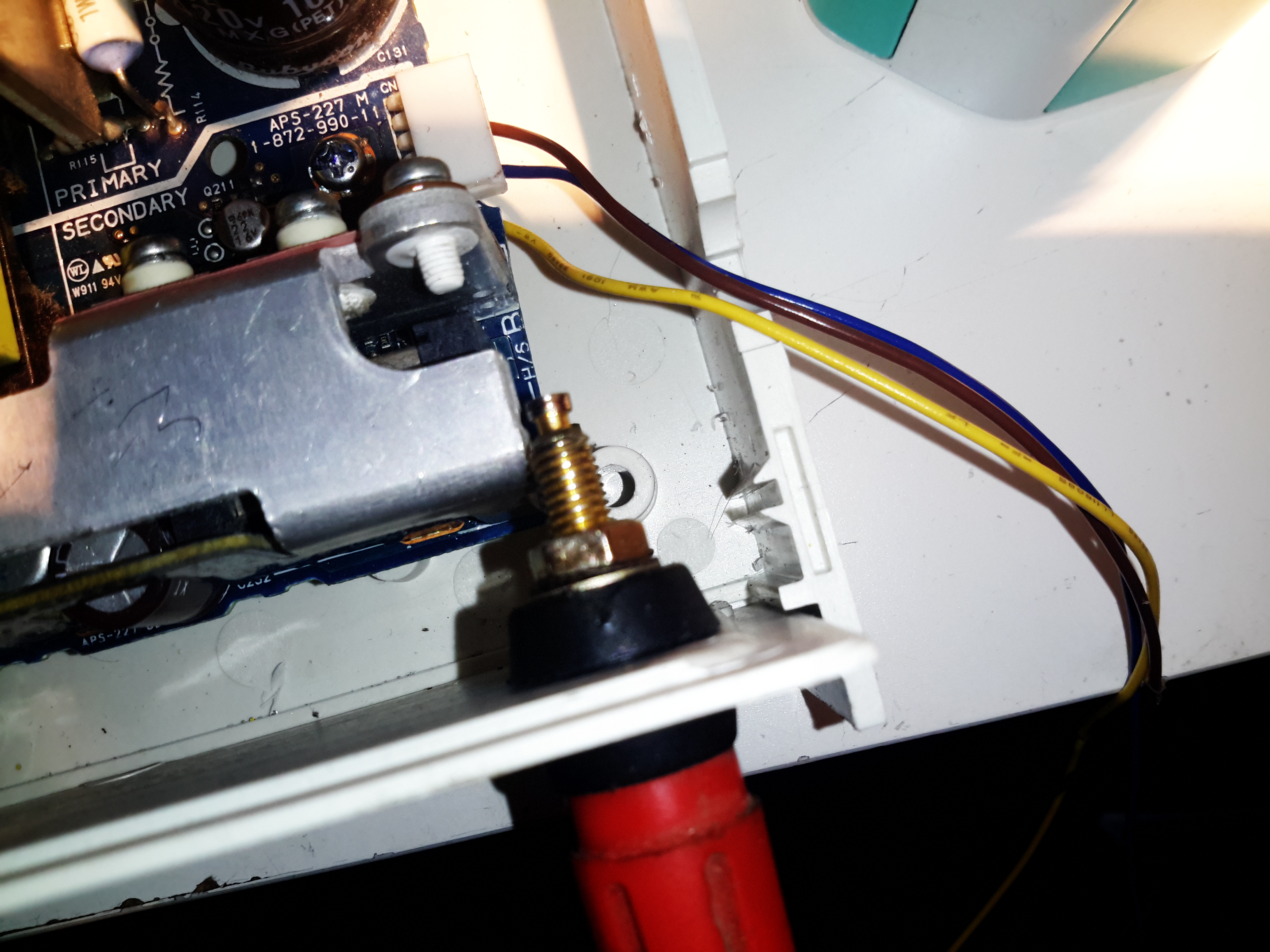
Terminal Posts
Here I’ve got the binding posts mounted, however the studs are a little too long. Once the wiring is installed these will be trimmed back to clear both the case screw path & the heatsink. (The heatsink isn’t a part of the power path anyway, so it’s isolated).
Power Meter Control Board & Fan
To keep the output rectifier MOSFETs cool, there’s a fan mounted in the upper shell just above their location, this case has vents in the bottom already moulded in for the air to exit. The fan is operated with the DC output contactor, only running when the main DC is switched on. This keeps the noise to a minimum when the supply doesn’t require cooling. The panel meter control board is also mounted up here, in the only empty space available. The panel meter module itself is a VAC-1030A from MingHe.
Meter Power Board
The measurement shunt & main power contactor for the DC output is on another board, here mounted on the left side of the case. The measurement shunt is a low-cost one in this module, I doubt it’s made of the usual materials of Manganin or Constantan, this is confirmed by my meansurements as when the shunt heats up from high-power use, the readings drift by about 100mA. The original terminal blocks this module arrived with have been removed & the DC cables soldered directly to the PCB, to keep the number of high-current junctions to a minimum. This should ensure the lowest possible losses from resistive heating.
Meter Panel Module
The panel meter module iself is powered from the 5v standby rail of the Sony PSU, instead of the 12v rail. This allows me to keep the meter on while the main 12v output is switched off.
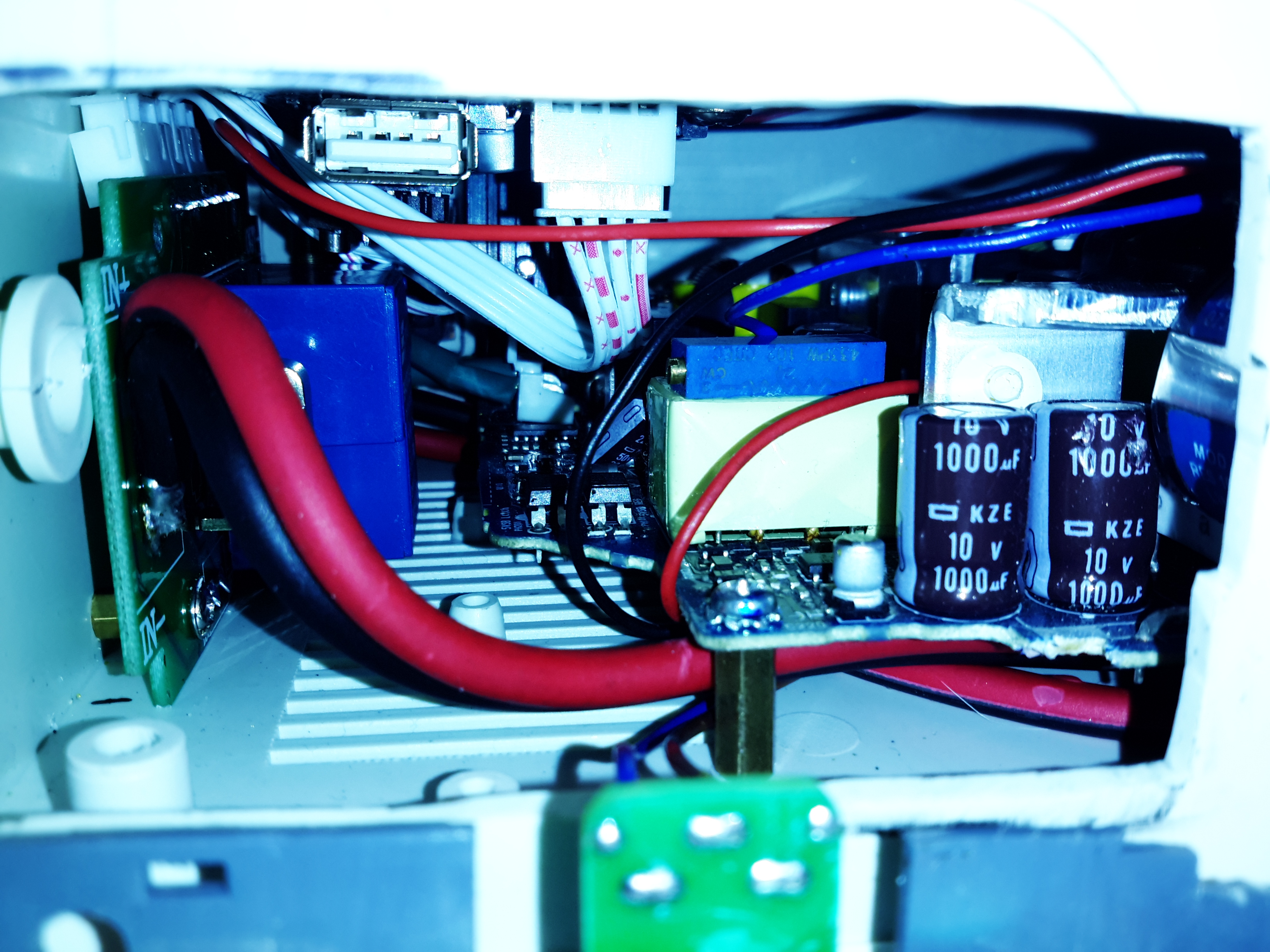
PSU Internals
here’s the supply with everything fitted to the lower shell – it’s a tight fit! A standard IEC connector has been fitted into the back panel for the mains input, giving much more clearance for the AC side of things.
Inside View
With the top shell in place, a look through the panel cutout for the meter LCD shows the rather tight fit of all the meter components. There’s about 25mm of clearance above the top of the PSU board, giving plenty of room for the 40mm cooling fan to circulate air around.
Load Test
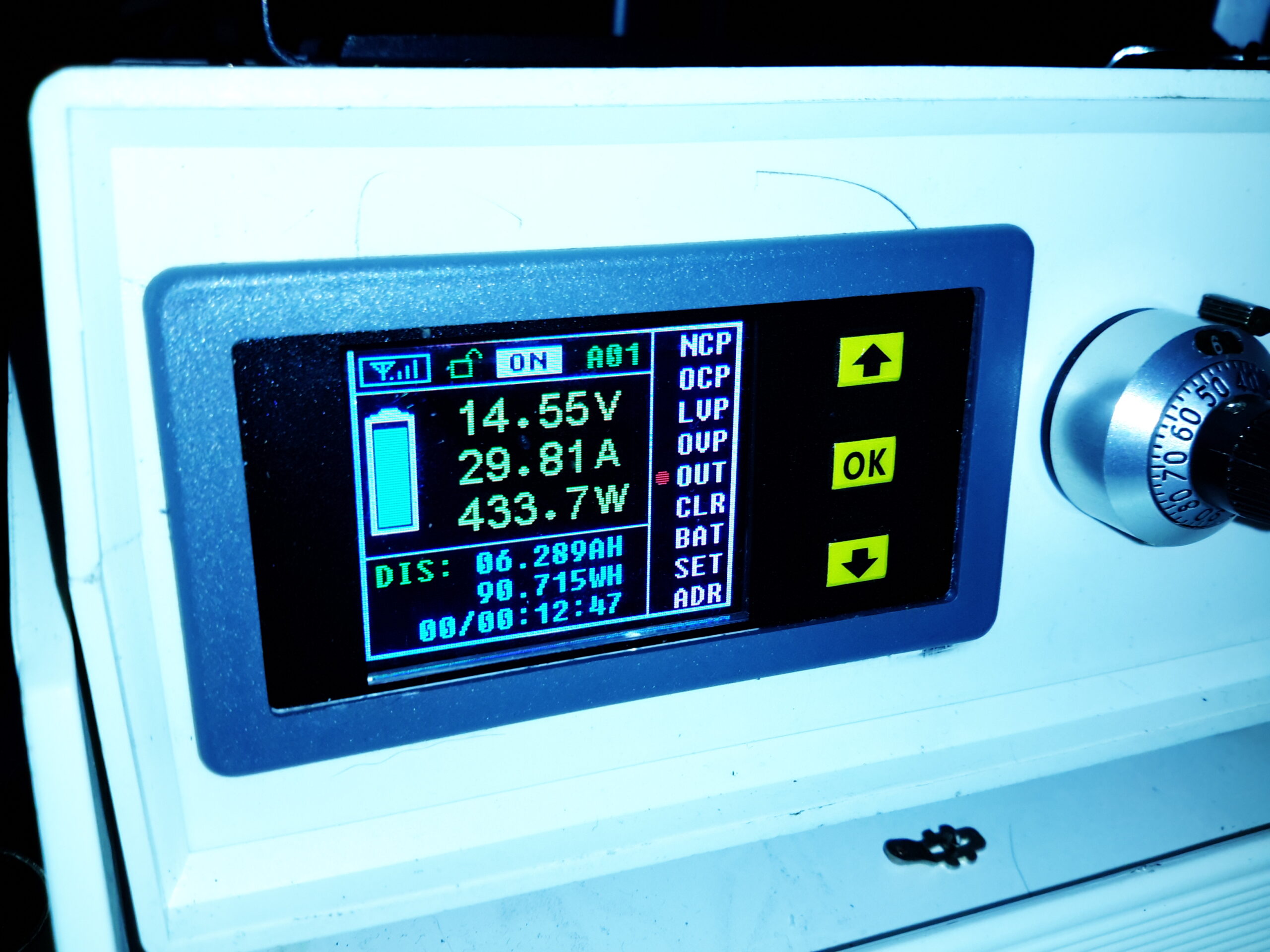
Here’s the finished supply under a full load test – it’s charging a 200Ah deep cycle battery. The meter offers many protection modes, so I’ve set the current limit at 30A – preventing Sony’s built in over current protection on the PSU tripping with this function is a bonus, as the supply takes a good 90 seconds to recover afterwards. I’ll go into the many modes & features of this meter in another post.
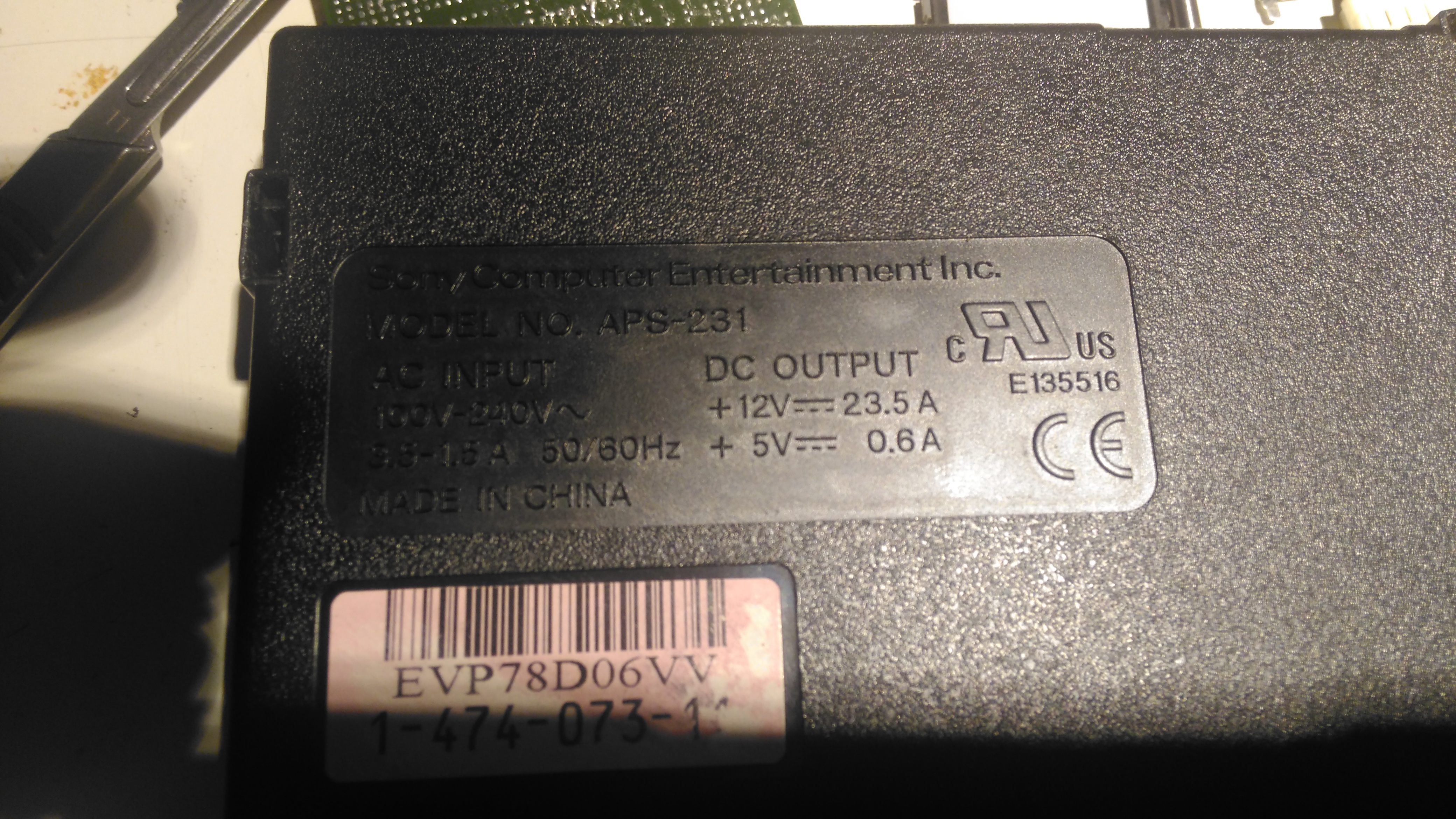
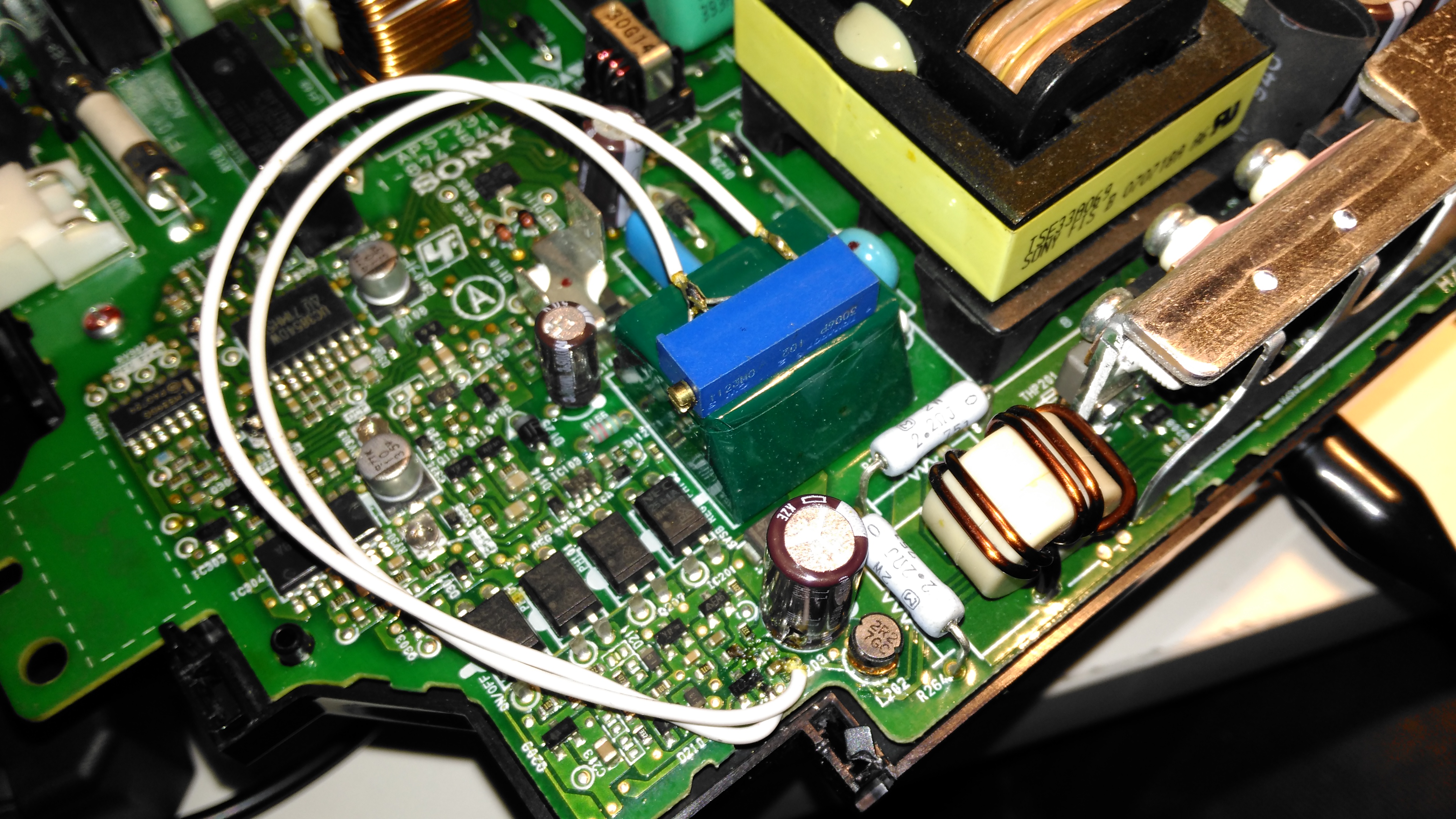
I was recently given a Sony PS3 with a dead disc drive, and since I’m not a console gamer I figured I’d see if there were any handy parts inside. Turns out these units contain a rather nice SMPS, the Sony APS-231 with a high power 12v rail, rated at 23.5A. A bit of searching around discovered a thread on the BadCaps Forums about voltage modding these supplies for a 13.8v output, suitable for my Ham radio gear.
These supplies are controlled by a Sony CXA8038A, for which there is very little information. Active PFC is included, along with synchronous rectification which increases the efficiency of the supply, and in turn, reduces the waste heat output from the rectifiers.
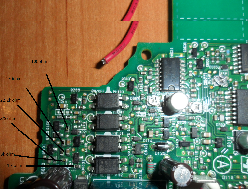
Regulation Section
Like many of the SMPS units I’ve seen, the output voltage is controlled by referencing it to an adjustable shunt reference, and adjusting the set point of this reference will in turn adjust the output voltage of the supply, this is done in circuit by a single resistor.
Here’s the regulator section of the PSU, with the resistors labelled. The one we’re after changing is the 800Ω one between pins 2 & 3 of the TS2431 shunt reference. It’s a very small 0402 size resistor, located right next to the filter electrolytic for the 5v standby supply circuit. A fine tip on the soldering iron is required to get this resistor removed.
Attachment Points
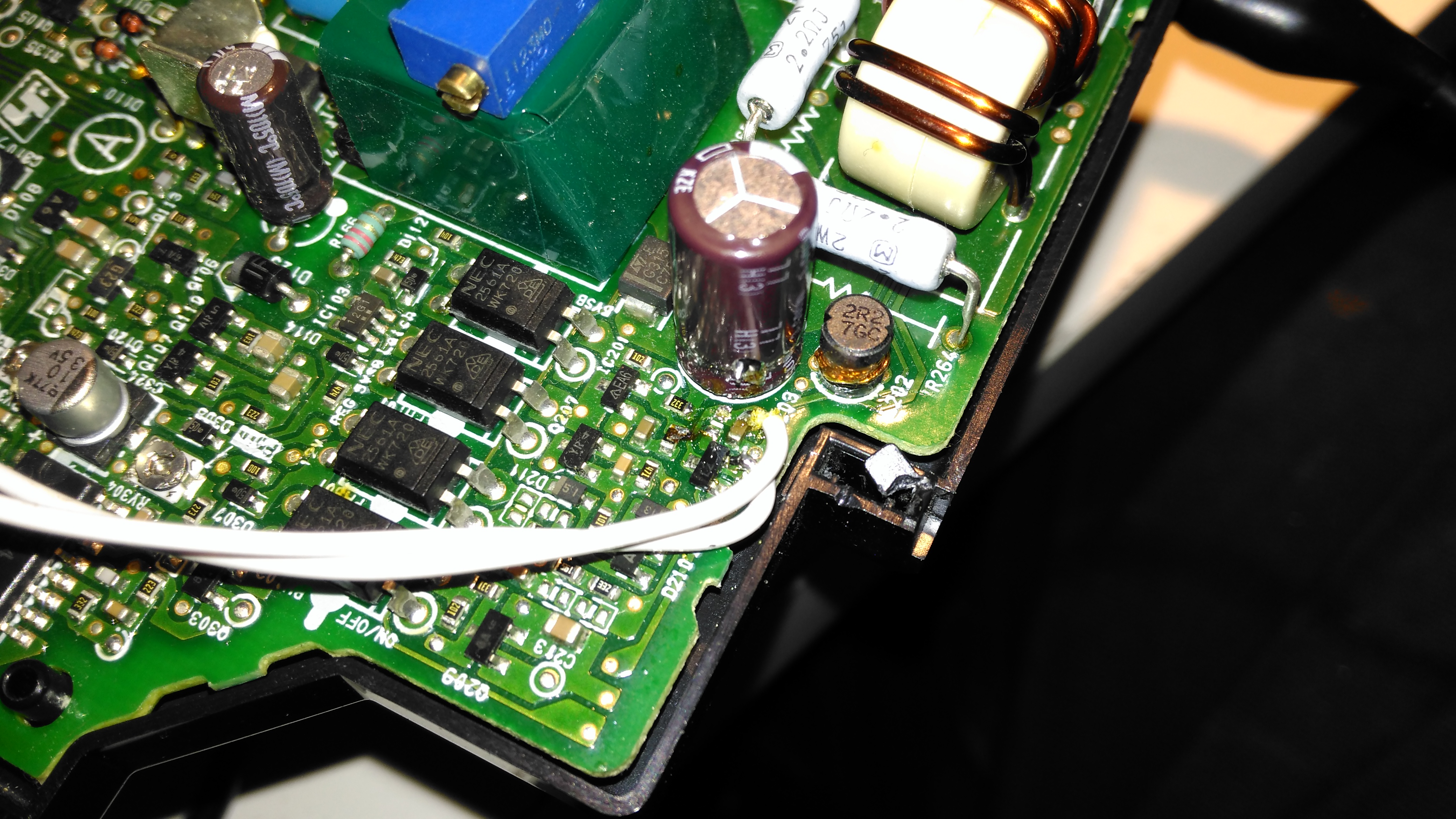
Once this resistor is removed from the circuit, a 1KΩ 18-turn potentiometer is fitted in it’s place, from the Anode (Pin 3) to the Ref. (Pin 2) pins of the TS2431 shunt reference. I initally set the potentiometer to be the same 800Ω as the factory set resistor, to make sure the supply would start up at a sensible voltage before I did the adjustment.
Potentiometer
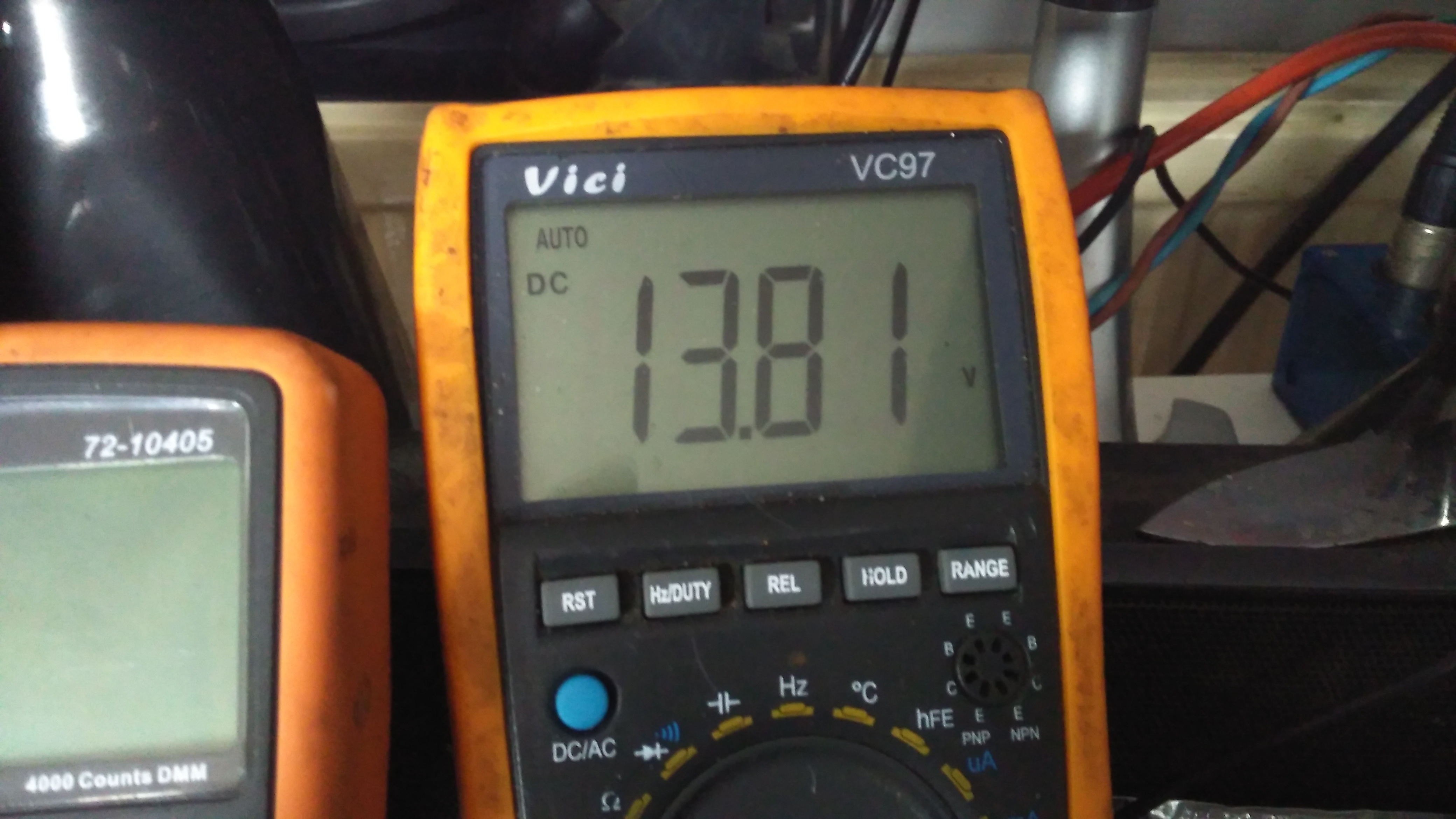
The pot is secured to the top of the standby supply transformer with a drop of CA glue to stop everything moving around. The supply can now be adjusted to a higher setpoint voltage – 13.8v is about the maxumum, as the OVP cuts the supply out at between 13.9v-14v.
Modded Voltage
After doing some testing at roughly 50% of the supply’s rated load, everything seems to be stable, and nothing is heating up more than I’d expect.
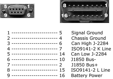
As I mentioned in the previous post, these heaters have a standard interface that’s used for control & diagnostics, the W-Bus. This is transmitted over the K-Line of the vehicle bus, and all heaters, regardless of firmware modifications done by the various car manufacturers respond to this interface. Official Webasto diagnostic adaptors are available, but these are just a very expensive serial adaptor. A much cheaper option is a ~£5 Universal ODB adaptor.
ODB2
Above shows the signals on the ODB connector – the ones we’re interested in here are Pin 16, the +12v supply, and Pin 7, K-Line. Connect Pin 16 to the positive supply to the heater, and Pin 7 to Pin 2 on the Webasto heater. (Valid for all TT-V heaters).
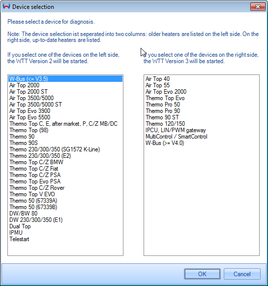
Device Selection
Once these two connections are made to the heater, fire up the Thermo Test software. The screen above will be displayed. Pick W-Bus at top left.
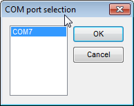
COM Port Selection
First thing, connect the ODB adaptor to USB, and change to the correct COM port in Thermo Test. There may be several in the list, but a newly connected USB device should show up with the highest COM number.
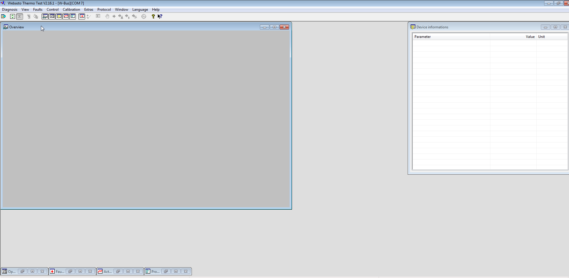
Thermo Test
Once Thermo Test is running, start communications by going to the Diagnosis Menu > Start Diagnostic (F2 keyboard shortcut).
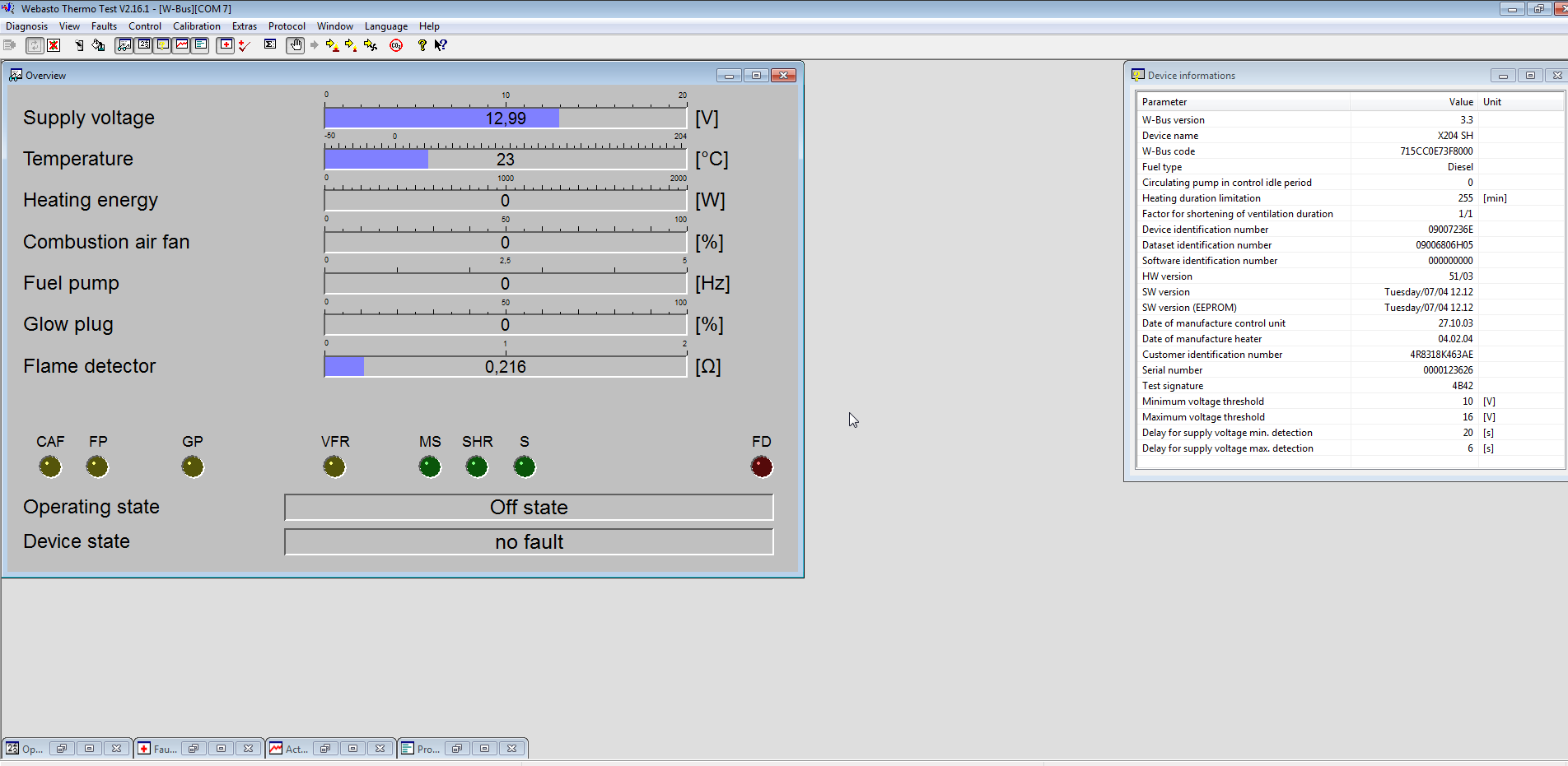
Initialized
After a few seconds, communication will be established. This will show faults, if any are present, and allow testing of the heater & it’s component parts. A summary report can be generated with Diagnosis > View Summary:
Diagnosis report                                               Webasto Thermosystems
------------------------------------------------------------------------------------------


Configuration:
--------------
  W-Bus version...............................................................3.3
  Device name.............................................................X204 SH
  W-Bus code.......................................................715CC0E73F8000
  Fuel type................................................................Diesel
  Circulating pump in control idle period.......................................0
  Heating duration limitation.................................................255 [min]
  Factor for shortening of ventilation duration...............................1/1
  Device identification number..........................................09007236E
  Dataset identification number.......................................09006806H05
  Software identification number........................................000000000
  HW version................................................................51/03
  SW version..................................................Tuesday/07/04 12.12
  SW version (EEPROM).........................................Tuesday/07/04 12.12
  Date of manufacture control unit.......................................27.10.03
  Date of manufacture heater.............................................04.02.04
  Customer identification number.....................................4R8318K463AE
  Serial number........................................................0000123626
  Test signature.............................................................4B42
  Minimum voltage threshold....................................................10 [V]
  Maximum voltage threshold....................................................16 [V]
  Delay for supply voltage min. detection......................................20 [s]
  Delay for supply voltage max. detection.......................................6 [s]

Operating data:
---------------
  Working hours.............................................................44:03 [h:m]
  Operating hours.........................................................5388:08 [h:m]
  Start count...............................................................19129
  Burning duration PH 1..33%.................................................0:00 [h:m]
  Burning duration PH 34..66%................................................0:00 [h:m]
  Burning duration PH 67..100%...............................................0:00 [h:m]
  Burning duration PH >100%..................................................0:00 [h:m]
  Burning duration SH 1..33%.................................................0:00 [h:m]
  Burning duration SH 34..66%................................................0:00 [h:m]
  Burning duration SH 67..100%...............................................0:00 [h:m]
  Burning duration SH >100%..................................................0:00 [h:m]
  Working duration PH........................................................0:51 [h:m]
  Working duration SH......................................................121:10 [h:m]
  Start counter PH..............................................................6
  Start counter SH............................................................854
  Ventilation duration.......................................................0:00 [h:m]

Error:
------

------------------------------------------------------------------------------------------
12.03.17  17:17:30                                       Webasto Thermo Test  2.16.1
This shows all the important stuff, including running hours. (5388Hrs on this heater!). Most importantly, there are no faults listed.
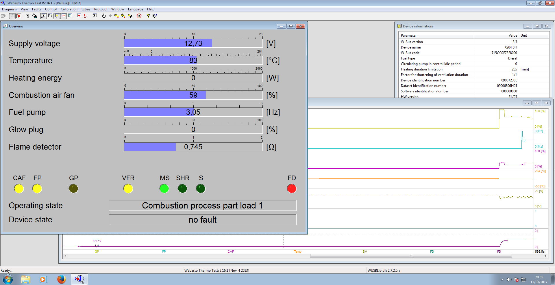
Heater Running
The heater can be fully tested by issuing a start command from the Command Menu > Parking Heating option. Obviously cooling water will be required for this, along with an external water pump. (The water pump control output on these heaters seems to be totally disabled in firmware, as they rely on the engine’s coolant pump). I used a bucket of water along with a small centrifugal pump to provide the cooling. During this test I noted that the firmware is much more aggressive in these units. The marine versions shut down at ~72°C water temperature, whereas these don’t so the same until ~90°C.
Now I’ve managed to communicate with the heater, I’ll get onto building a standalone controller so I can dispense with the Windows VM for control.
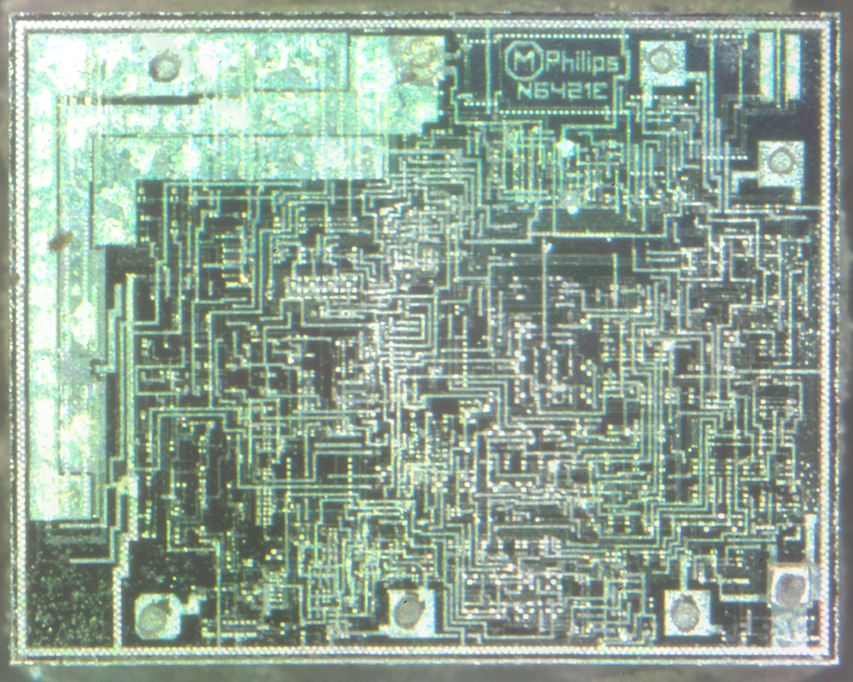
This is a chip aimed at the automotive market – this is a low power voltage regulator for supplying power to microcontrollers, for instance in a CD player.
TDA3606 Die
The TDA3606 is a voltage regulator intended to supply a microprocessor (e.g. in car radio applications). Because of low voltage operation of the application, a low-voltage drop regulator is used in the TDA3606. This regulator will switch on when the supply voltage exceeds 7.5 V for the first time and will switch off again when the output voltage of the regulator drops below 2.4 V. When the regulator is switched on, the RES1 and RES2 outputs (RES2 can only be HIGH when RES1 is HIGH) will go HIGH after a fixed delay time (fixed by an external delay capacitor) to generate a reset to the microprocessor. RES1 will go HIGH by an internal pull-up resistor of 4.7 kΩ, and is used to initialize the microprocessor. RES2 is used to indicate that the regulator output voltage is within its voltage range. This start-up feature is built-in to secure a smooth start-up of the microprocessor at first connection, without uncontrolled switching of the regulator during the start-up sequence. All output pins are fully protected. The regulator is protected against load dump and short-circuit (foldback
current protection). Interfacing with the microprocessor can be accomplished by means of a battery Schmitt-trigger and output buffer (simple full/semi on/off logic applications). The battery output will go HIGH when the battery input voltage exceeds the HIGH threshold level.
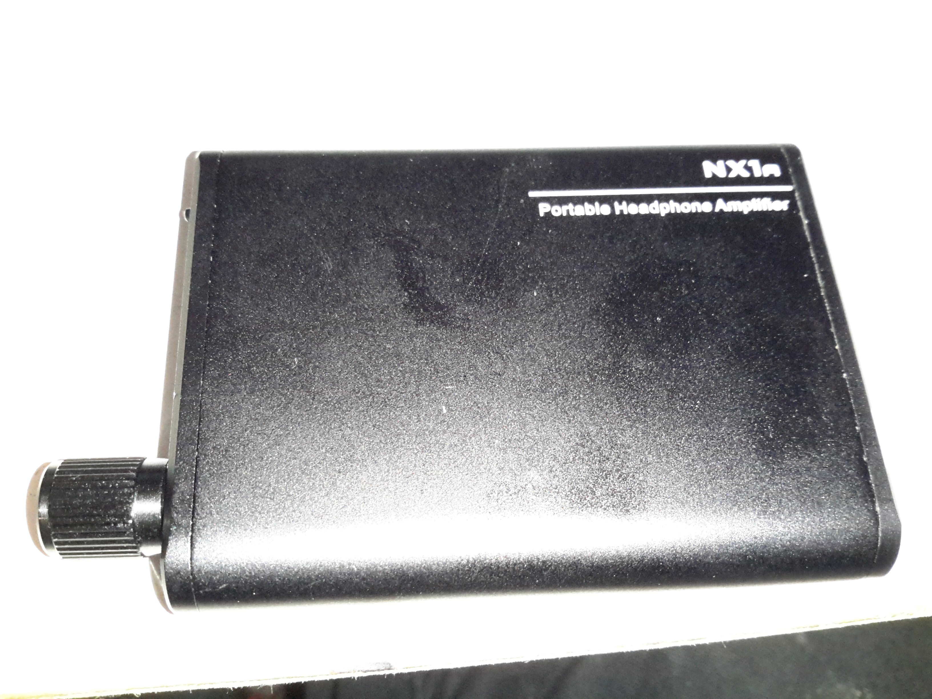
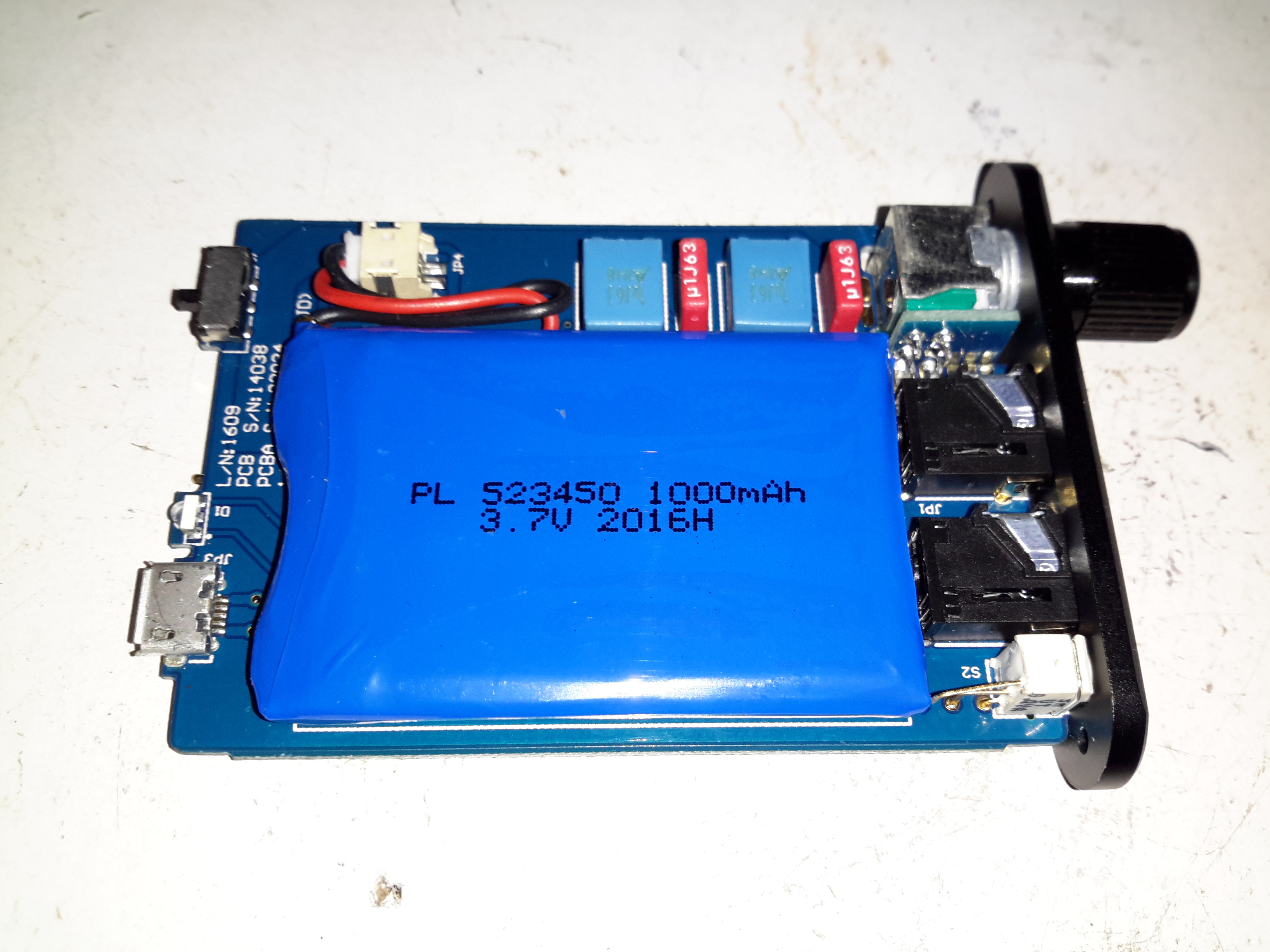
Time for another teardown! Here’s a pocket-sized headphone amplifier for use with mobile devices. This unit is powered by a built-in lithium cell, and can give some pretty impressive volume levels given it’s small size.
Audio Connections
The 3.5mm audio input & output jacks are on the front of the unit, along with the relatively enormous volume knob & power switch. There’s a little blue LED under the switch that lets the user know when the power is on, but this is a very sedate LED, using very little power.
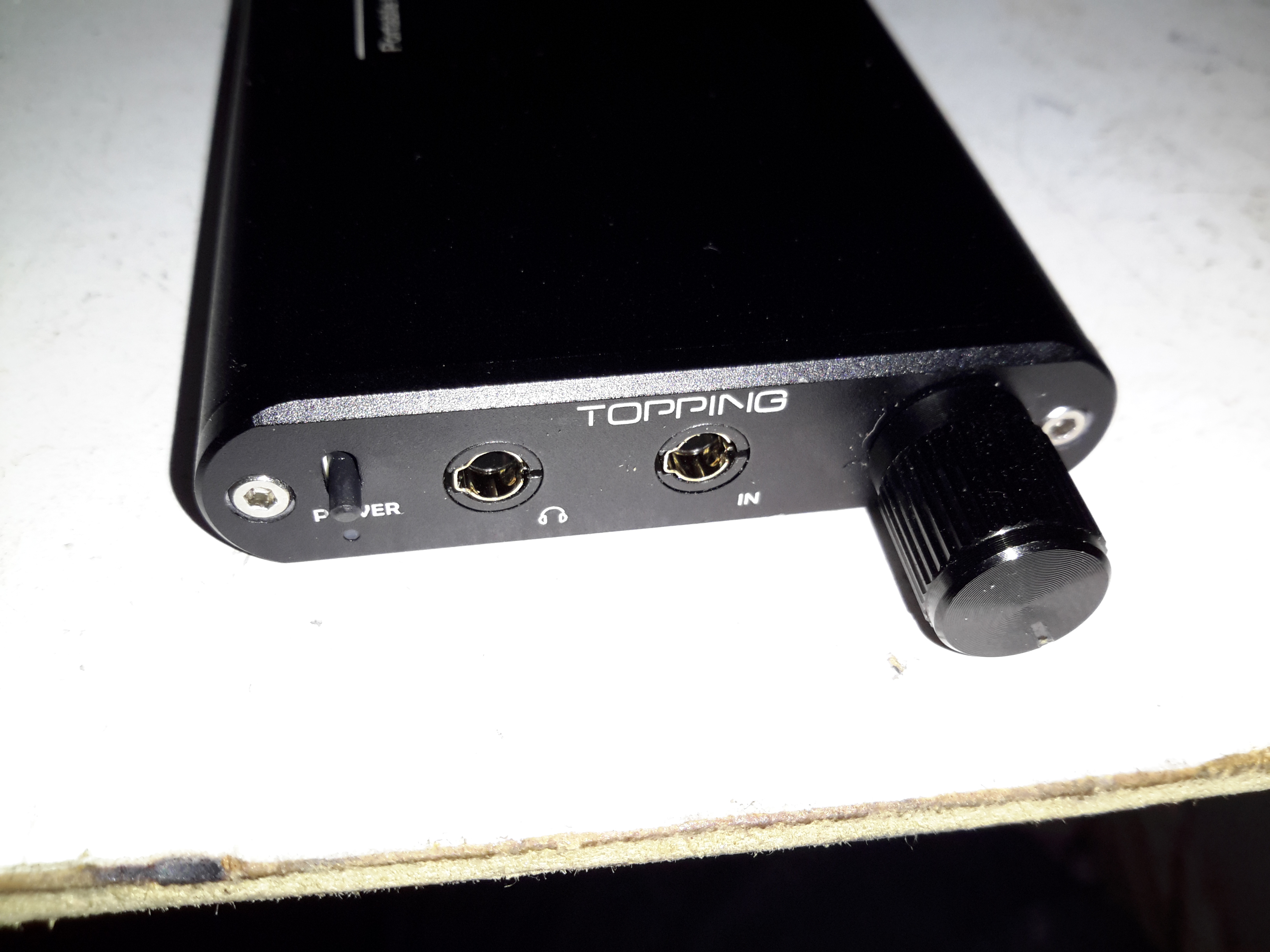
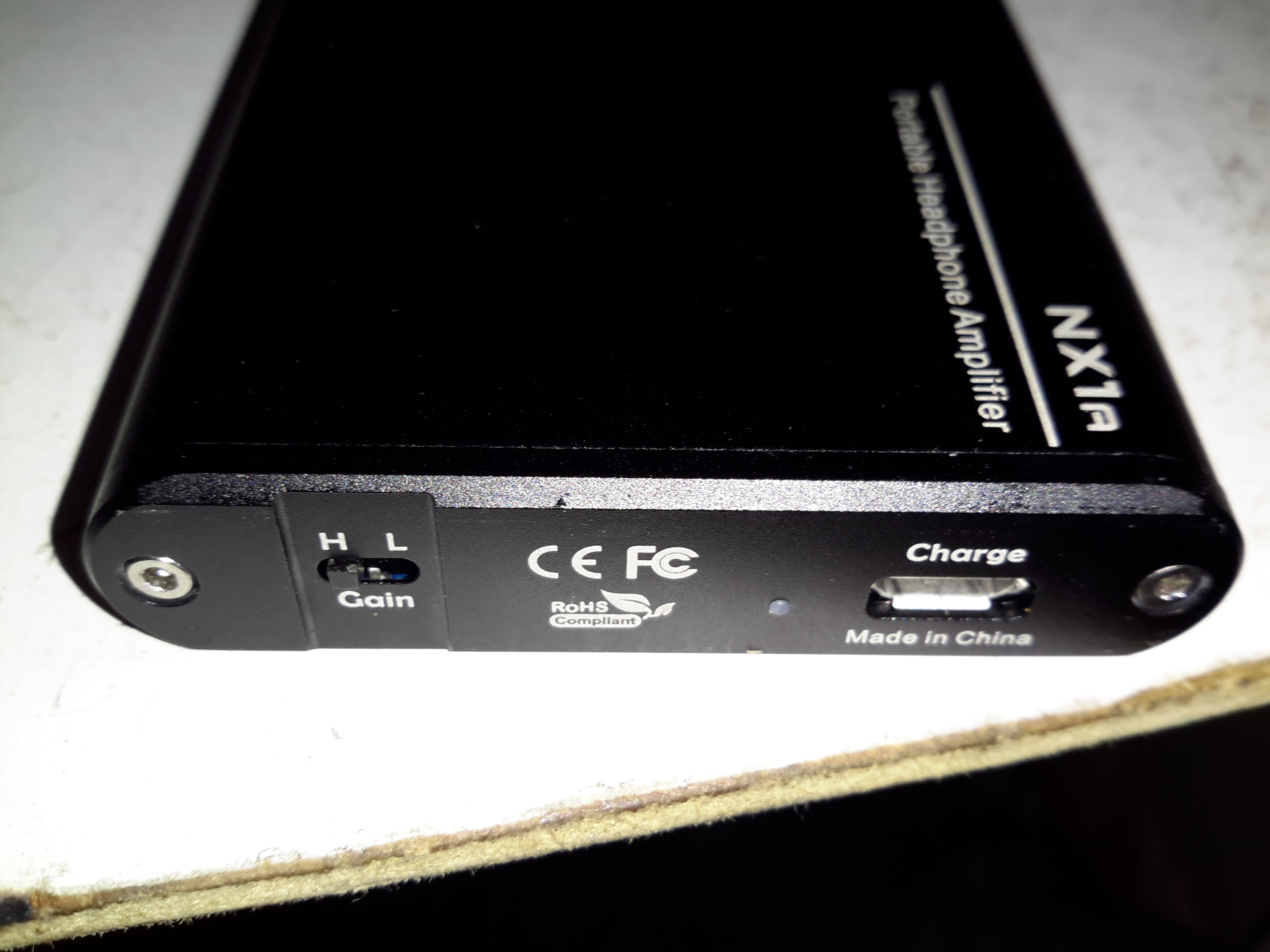
Gain & Charging
On the back is the High-Low gain switch, and the µUSB charging port. There’s another indicator LED to show that the internal cell is charging, in this case a red one.
PCB Top
Removing a couple of cap screws allows the internals to slide out of the extruded aluminium casing. Most of the internal space is taken up by the 1Ah lithium cell, here on the top of the PCB secured by some double-sided tape. The volume potentiometer is mounted on a small daughterboard at right angles to get it to fit into the small vertical space in the case.
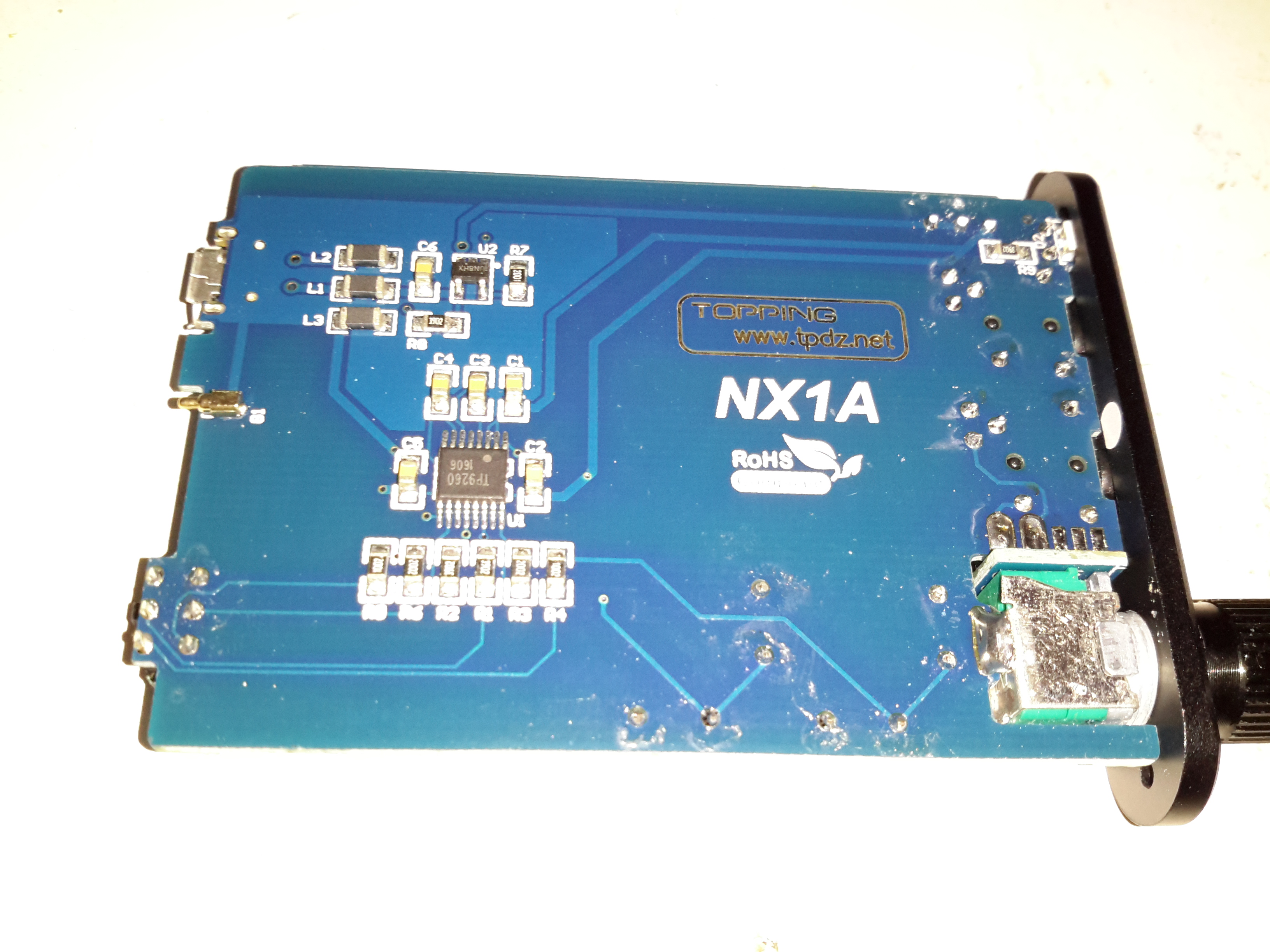
PCB Rear
The bottom of the PCB is equally as sparse – the only ICs being the main audio amp in the centre & the battery charger IC at the top.
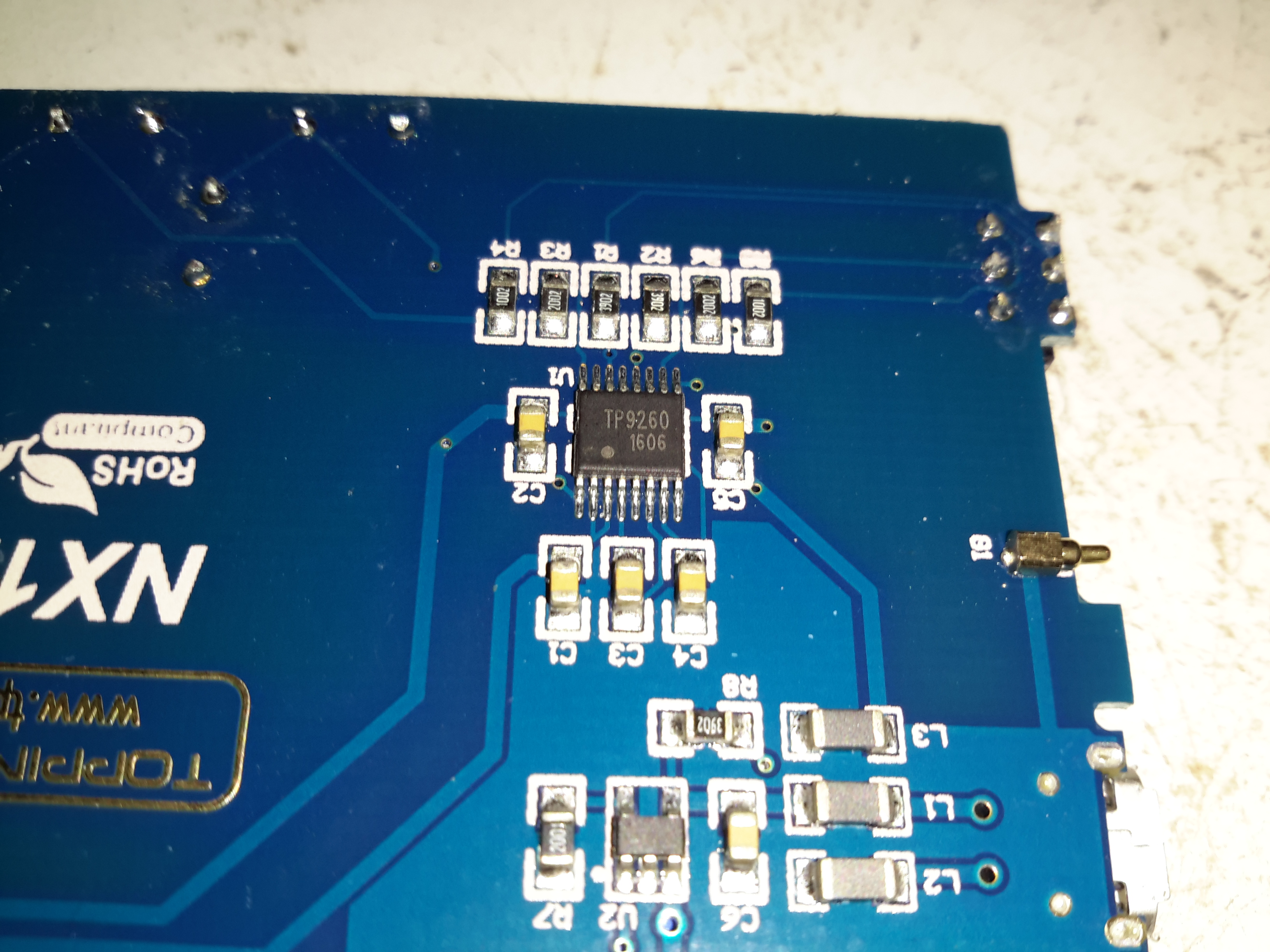
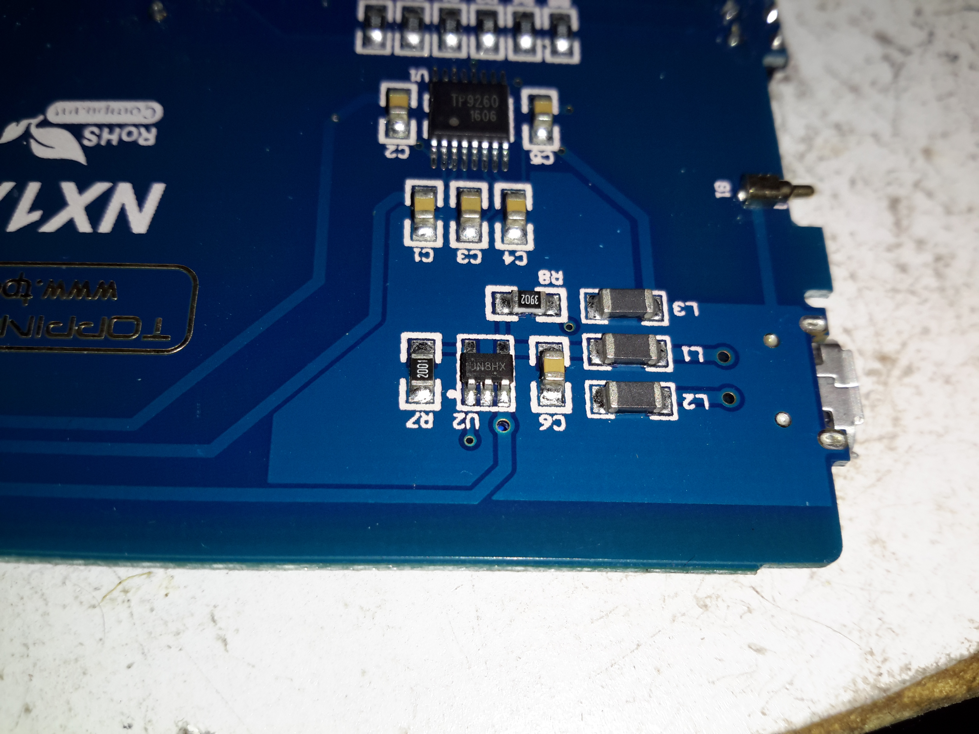
Amplifier IC
The main audio amplifier is a TP9260, I couldn’t find a datasheet on this, so I’m unsure of what the specs are. The row of resistors above the IC are for the gain divider circuit. There’s also a pogo pin on the right that makes contact with the back panel of the case for grounding.
Battery Charger
Battery charging is taken care of by a UN8HX 500mA linear charging IC, not much special here.
This little amplifier seems to be pretty well made, considering the price point. The only issue I’ve had so far is the audio cables act like antennas, and when in close proximity to a phone some signal gets picked up & blasted into the headphones as interference.
With the installation of the new diesel fired heater we’ve noticed a small problem – since the only heat source in the saloon is the stove, even with the diesel heater fired up the temperature doesn’t really change much, as the heat from the radiators in the both the cabins & the head isn’t spreading far enough.
The solution to this problem is obviously an extra radiator in the saloon, however there isn’t the space to fit even a small domestic-style radiator. eBay turned up some heater matrix units designed for kit cars & the like:
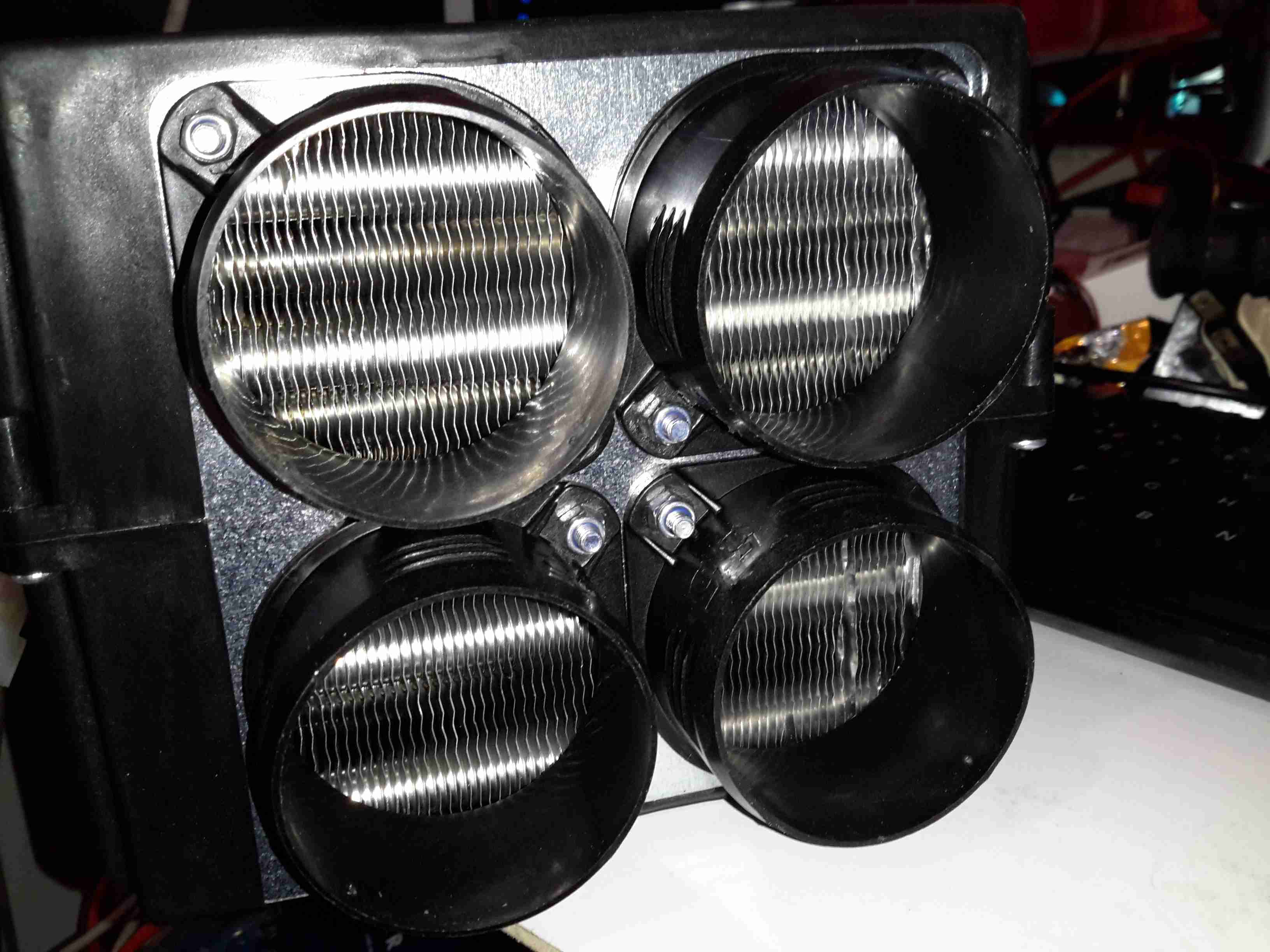
3.8kW Matrix
These small heater matrix units are nice & compact, so will fit into the back of a storage cupboard next to the saloon. Rated at a max heat output of 3.8kW, just shy of the stove’s rated 4kW output power, this should provide plenty of heating when we’re running the diesel heater rather than the fire.
Water & Power
The blower motor has a resistor network to provide 3 speeds, but this probably won’t be used in this install, water connections are via 15mm copper tails. The current plan is to use a pipe thermostat on the flow from the boiler to switch on the blower when the water temperature reaches about 40°C.
Hot Air Outlets
The hot air emerges from the matrix via 4 55mm duct sockets. This gives enough outlets to cover both the saloon & the corridor down to the cabins.
Hot Air Vents
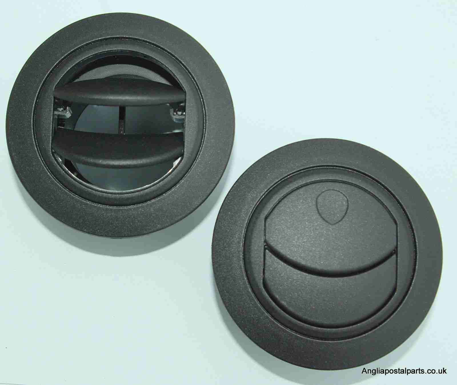
Standard 60mm Eberspacher style vents will be used to point the warmth where it’s needed.
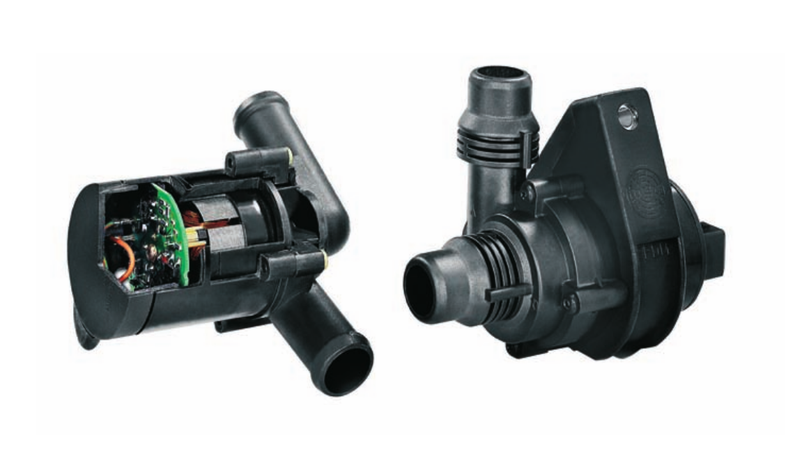
With some recent upgrades to the boat’s heating system, the hot water circulation pumps we’ve been using are becoming far too small for the job. After the original Johnson Marine circulation pump died of old age (the brushes wore down so far the springs ate the commutator) some time ago, it was replaced with a Pierburg WUP1 circulation pump from a BMW. (As we’re moored next to a BMW garage, these are easily obtainable & much cheaper than the marine pumps).
WUP1 Cutaway
These are also brushless, where as the standard Johnson ones are brushed PM motors – the result here is a much longer working life, due to fewer moving parts.
The rated flow & pressure on these pumps is pretty pathetic, at 13L/min at 0.1bar head pressure. As the boat’s heating system is plumbed in 15mm pipe instead of 22mm this low pressure doesn’t translate to a decent flow rate. Turns out it’s pretty difficult to shove lots of water through ~110ft of 15mm pipe ;). Oddly enough, the very low flow rate of the system was never a problem for the “high output” back boiler on the stove – I suspect the “high output” specification is a bit optimistic.
This issue was recently made worse with the addition of a Webasto Thermo Top C 5kW diesel-fired water heater, which does have it’s own circulation pump but the system flow rate was still far too low to allow the heater to operate properly. The result was a rapidly cycling heater as it couldn’t dump the generated hot water into the rest of the system fast enough.
The easiest solution to the problem here is a larger pump with a higher head pressure capability. (The more difficult route would be completely re-piping the system in 22mm to lower the flow resistance). Luckily Pierburg produce a few pumps in the range that would fit the job.
Pierburg CWA-50
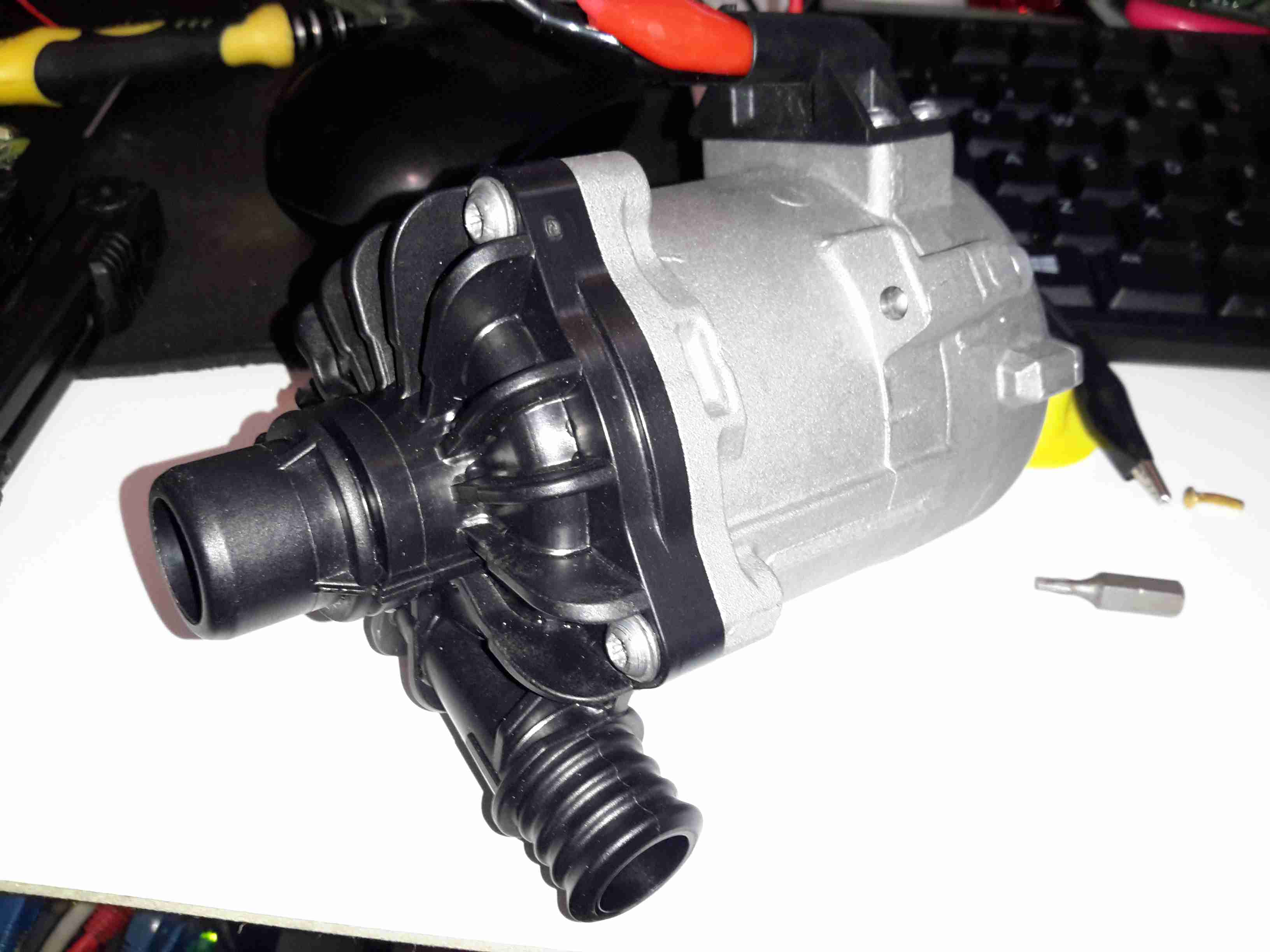
Here’s the next size up from the original WUP1 pump, the CWA50. These are rated at a much more sensible 25L/min at 0.6bar head pressure. It’s physically a bit larger, but the connector sizes are the same, which makes the install onto the existing hoses easier. (For those that are interested, the hose connectors used on BMW vehicles for the cooling system components are NormaQuick PS3 type. These snap into place with an O-Ring & are retained by a spring clip).
The CWA50 draws considerably more power than the WUP1 (4.5A vs 1.5A), and are controllable with a PWM signal on the connector, but I haven’t used this feature. The PWM pin is simply tied to the positive supply to keep the pump running at maximum speed.
Once this pump was installed the head pressure immediately increased on the gauge from the 1 bar static pressure to 1.5 bar, indicating the pump is running at about it’s highest efficiency point. The higher water flow has so far kept the Webasto happy, there will be more to come with further improvements!
CWA-50 Pump Teardown
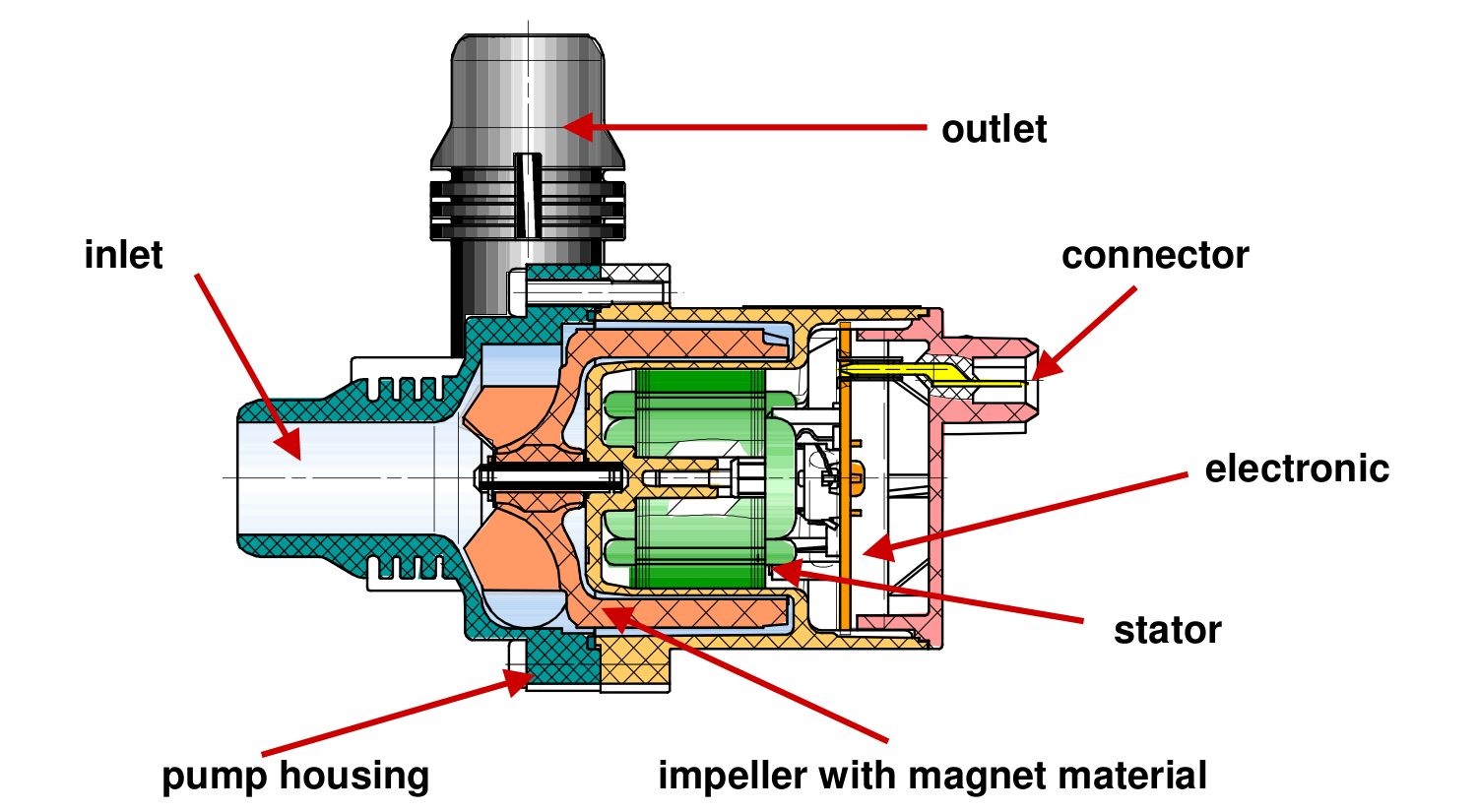
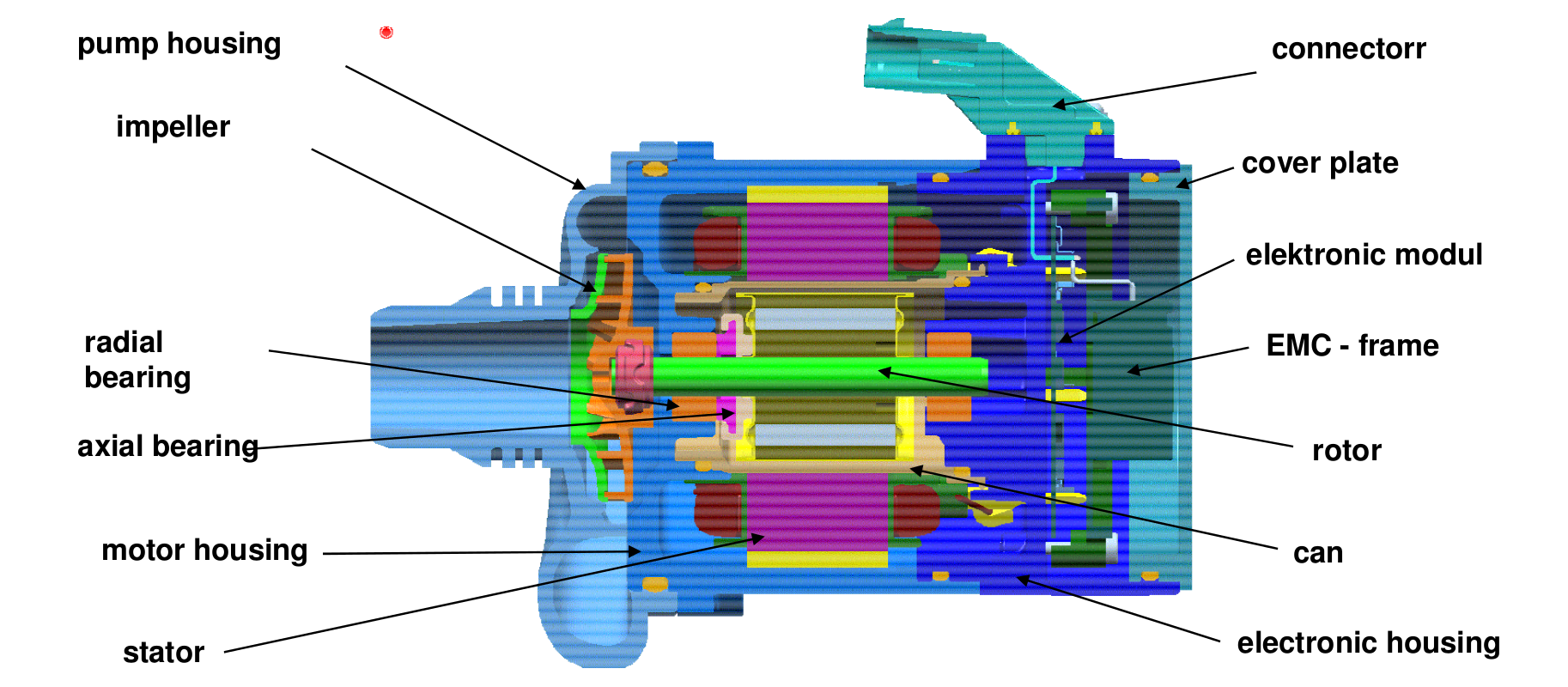
CWA50 Cutaway
Above is a cutaway drawing of the new pump. These have a drilling through the shaft allows water to pass from the high pressure outlet fitting, through the internals of the pump & returns through the shaft to the inlet. This keeps the bearings cool & lubricated. The control & power drive circuitry for the 3-phase brushless motor is attached to the back & uses the water flowing through the rotor chamber as a heatsink. Overall these are very well made pumps.
Impeller
Here’s the impeller of the pump, which is very small considering the amount of power this unit has. The return port for the lubricating water can be seen in the centre of the impeller face.
3-Phase Driver
Inside the back of the pump is the control module. The main microcontroller is hiding under the plastic frame which holds the large power chokes & the main filter electrolytic.
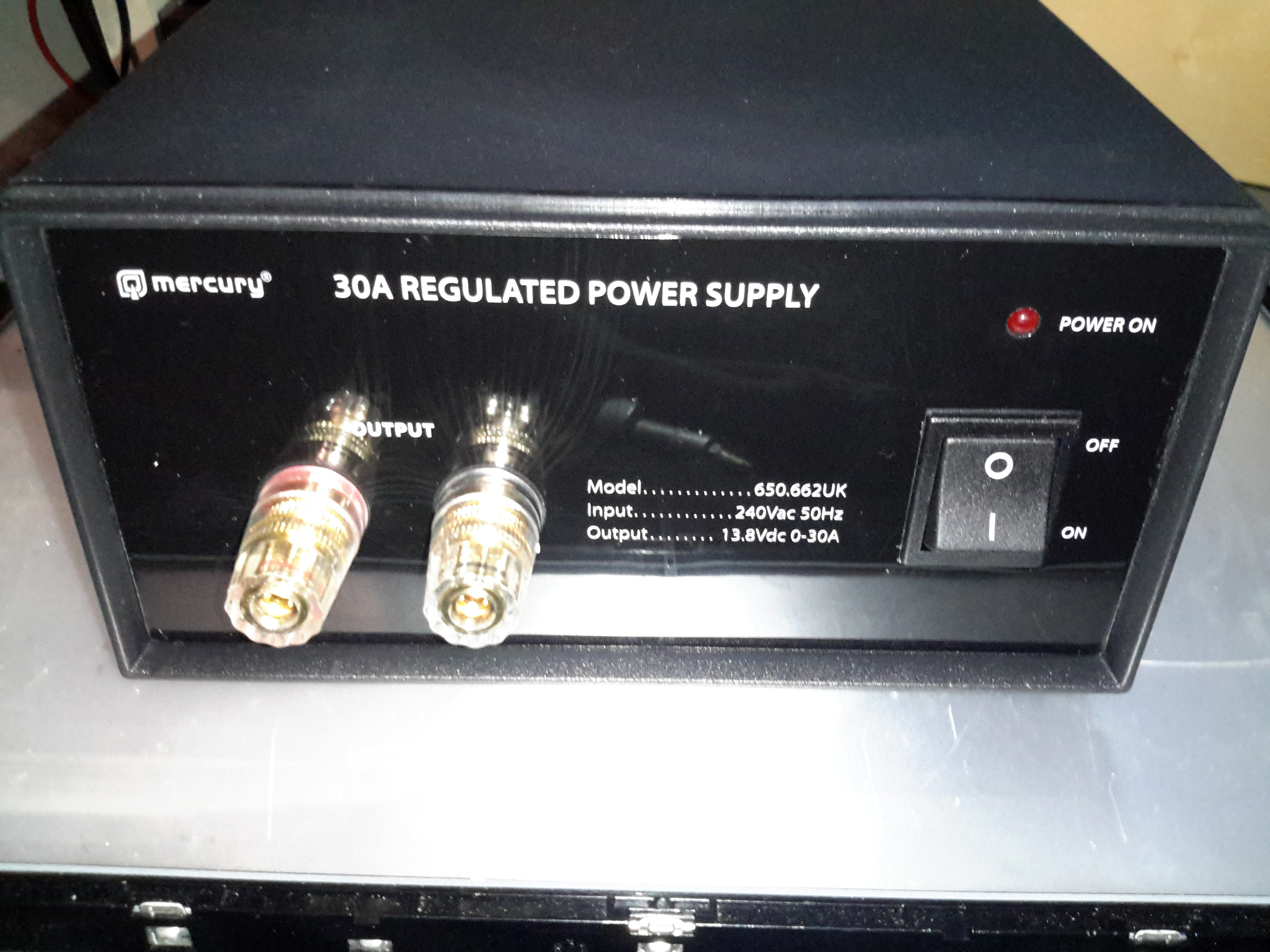
After having a couple of the cheap Chinese PSUs fail on me in a rather spectacular fashion, I decided to splash on a more expensive name-brand PSU, since constantly replacing PSUs at £15 a piece is going to get old pretty fast. This is the 30A model from Mercury, which seems to be pretty well built. It’s also significantly more expensive at £80. Power output is via the beefy binding posts on the front panel. There isn’t any metering on board, this is something I’ll probably change once I’ve ascertained it’s reliability. This is also a fixed voltage supply, at 13.8v.
Rear Panel
Not much on the rear panel, just the fuse & cooling fan. This isn’t temperature controlled, but it’s not loud. No IEC power socket here, the mains cable is hard wired.
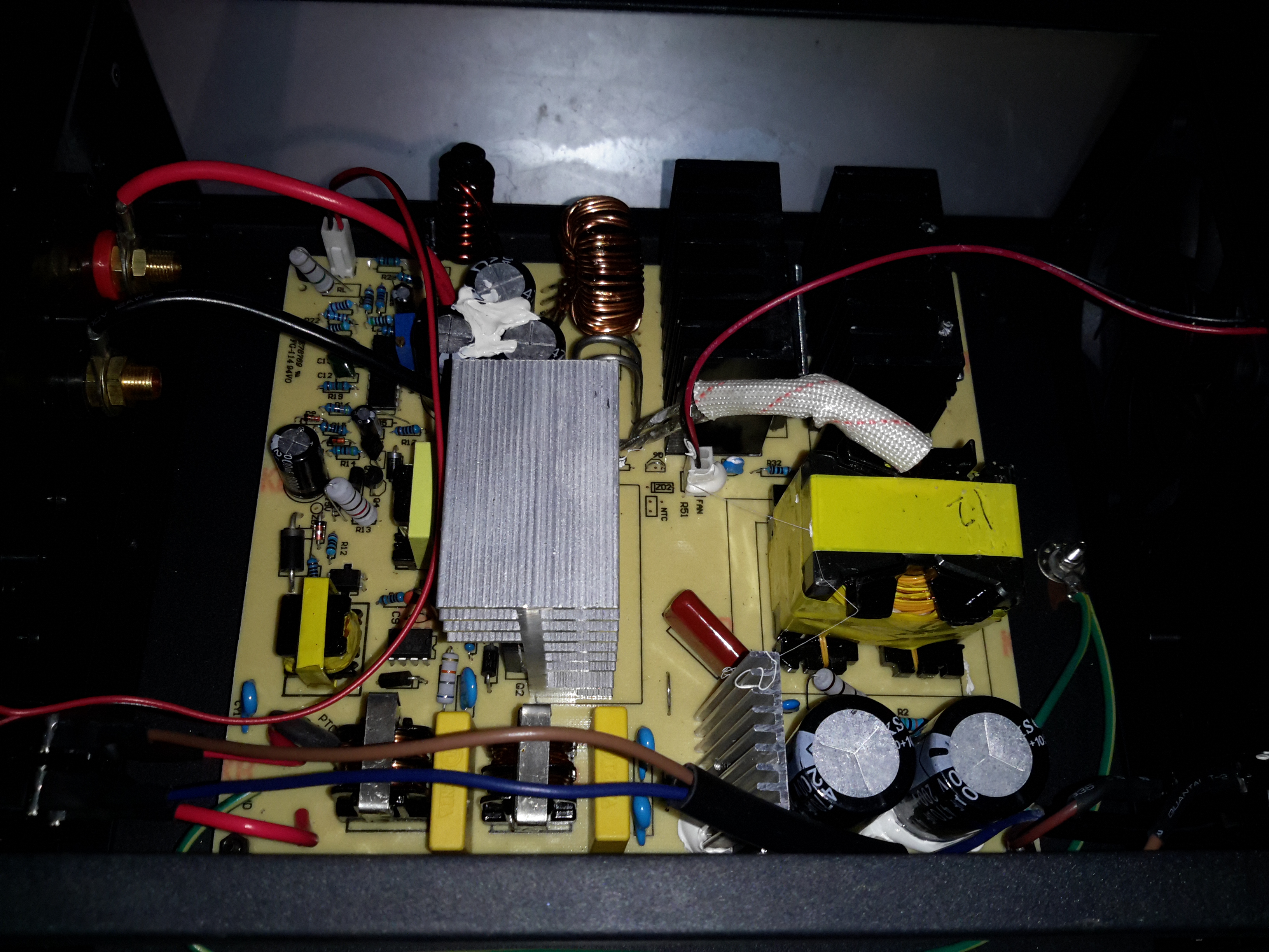
Main Board
Removing some spanner-type security screws reveals the power supply board itself. Everything on here is enormous to handle the 30A output current at 13.8v. The main primary side switching transistors are on the large silver heatsink in the centre of the board, feeding the huge ferrite transformer on the right.
Transformer
The transformer’s low voltage output tap comes straight out instead of being on pins, due to the size of the winding cores. Four massive diodes are mounted on the black heatsinks for output rectification.
SMPS Controller
The supply is controlled via the jelly bean TL494 PWM controller IC. The multi-turn potentiometer doesn’t adjust the output voltage, more likely it adjusts the current limit.
Standby Supply
Power to initially start the supply is provided by a small SMPS circuit, with a VIPer22A Low Power Primary Switcher & small transformer on the lower right. The transformer upper left is the base drive transformer for the main high power supply.
Here’s the other TV that was picked up from the local water point having been put of to be recycled. This one is much newer than the Thorn TV, a 10″ colour version from Ferguson.
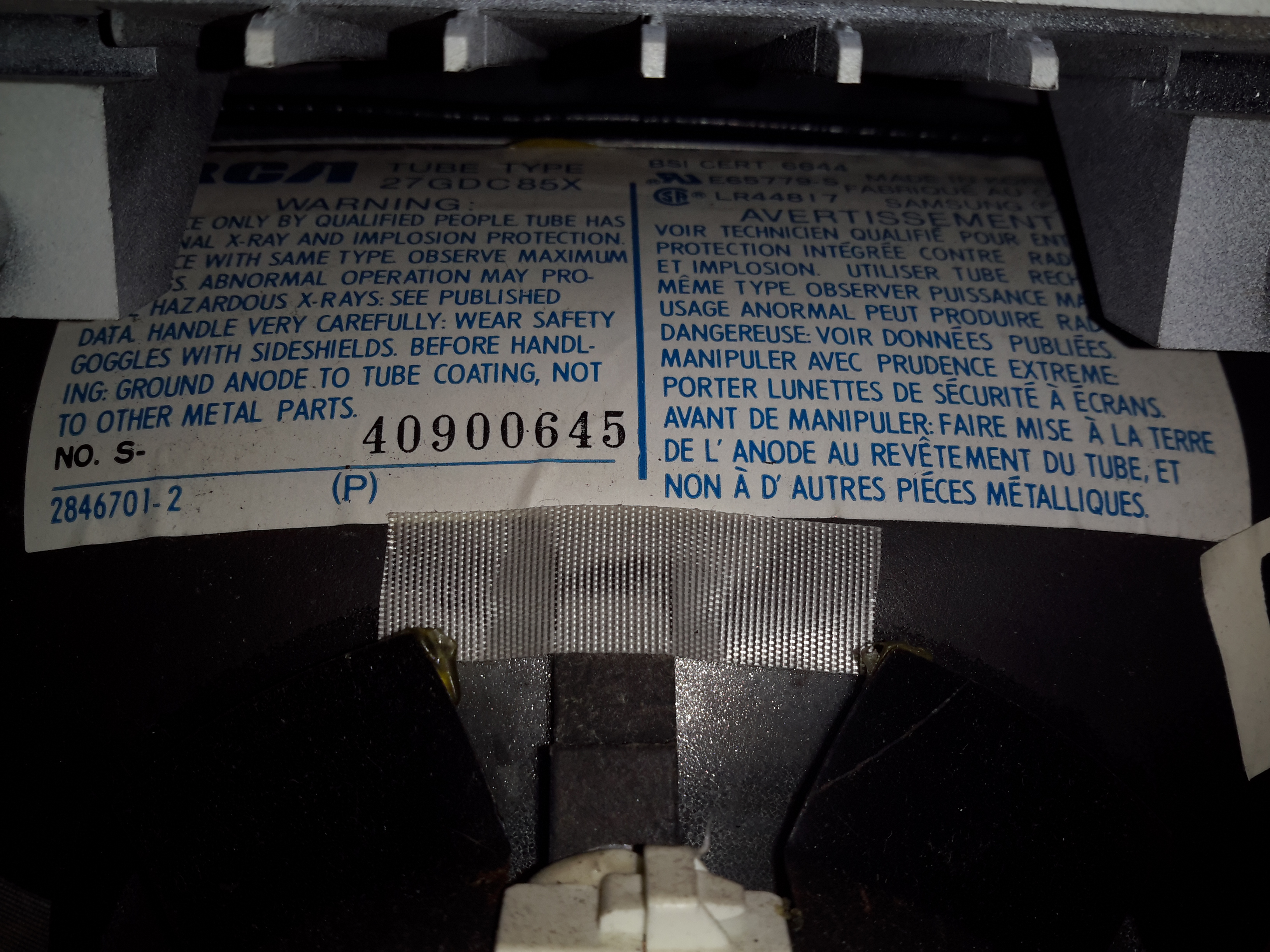
RCA 27GDC85X CRT
The colour CRT used is an RCA branded one, 27GDC85X.
Power Inputs
Like the other TV, this one is dual voltage input, mains 240v & 12v battery. This TV is a factory conversion of a standard 240v AC chassis though.
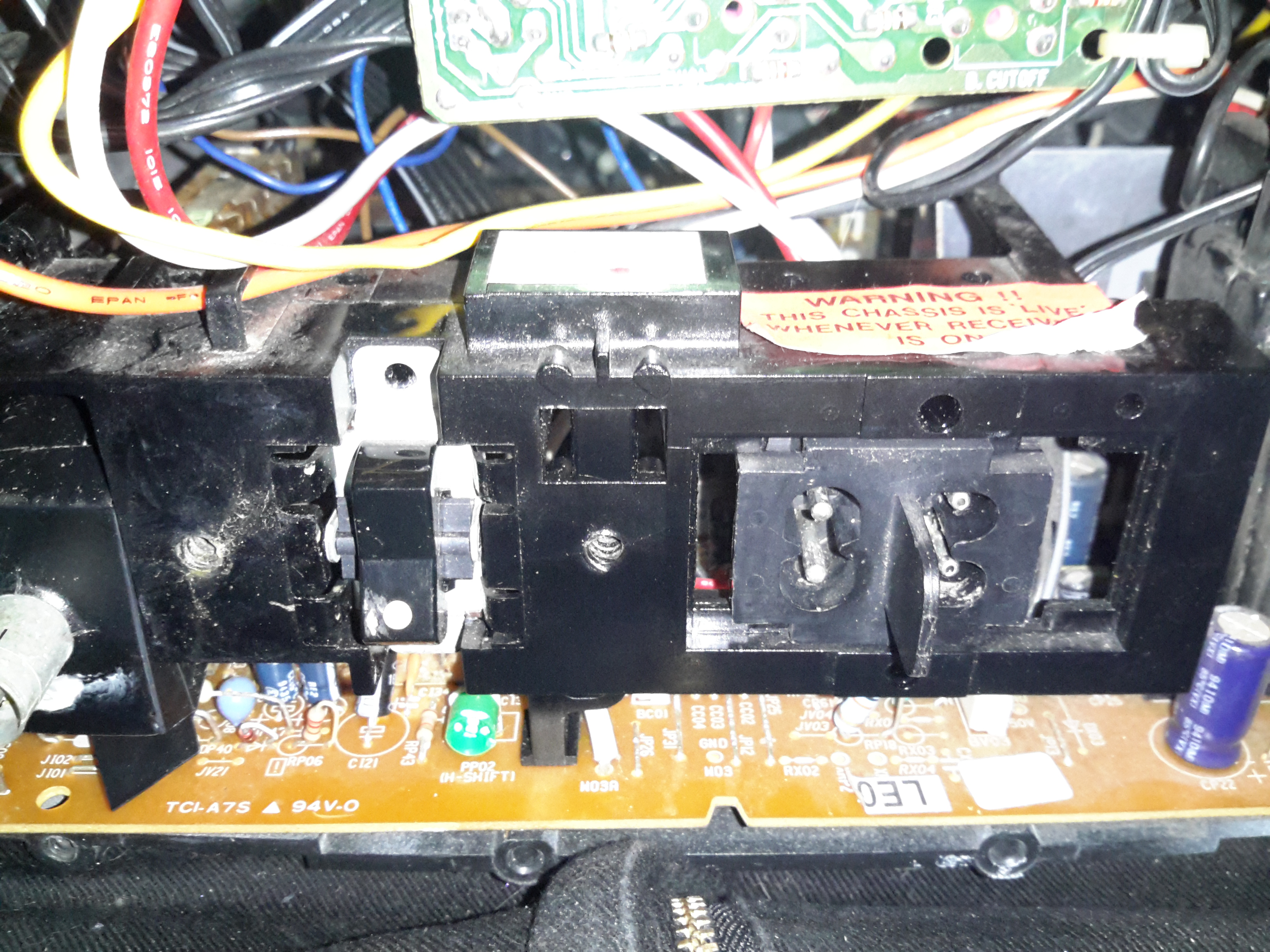
HV PSU
The 12v power first goes into this board, which looked suspiciously like an inverter. Measuring on the output pins confirmed I was right, this addon board generates a 330v DC supply under a load, but it’s not regulated at all, under no load the output voltage shoots up to nearly 600v!
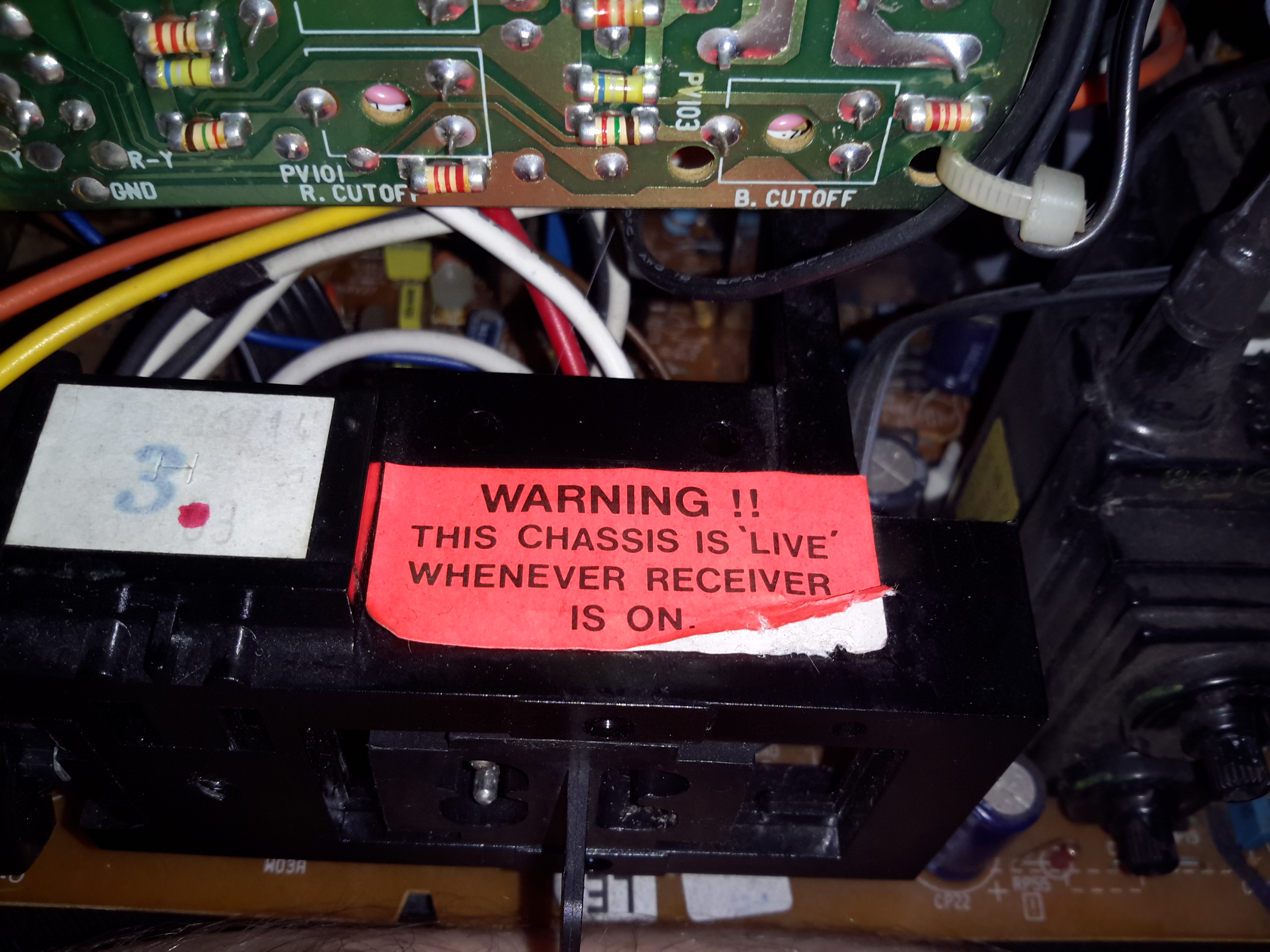
Live Chassis
I’ve not seen one of these labels on a TV for many years, when back in the very old TV sets the steel chassis would be used to supply power to parts of the circuitry, to save on copper. Although it doesn’t have a metal chassis to actually become live, so I’m not sure why it’s here.
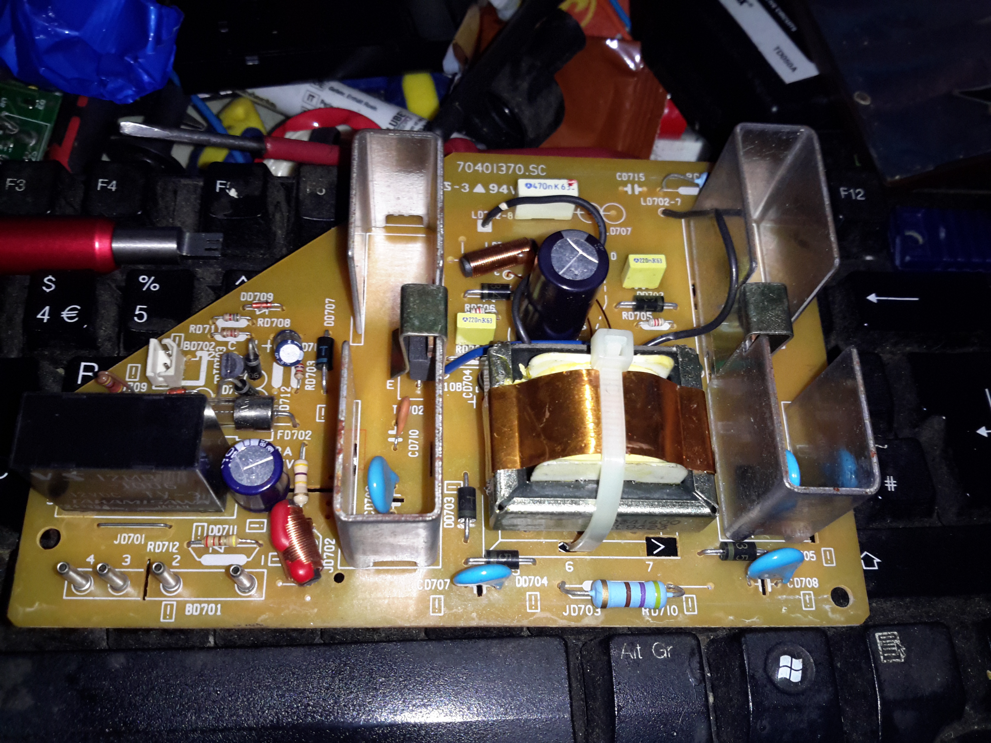
Main PCB
The main PCB is much more integrated in this newer TV, from the mid 90’s, everything is pretty much taken care of by silicon by this point.
Main Microcontroller
This Toshiba µC takes care of channel switching & displaying information on the CRT. The tuner in this TV is electronically controlled.
PAL Signal Processor
The video signal is handled by this Mitsubishi IC, which is a PAL Signal Processor, this does Video IF, Audio IF, Chroma, & generates the deflection oscillators & waveforms to drive the yoke.
CRT Adjustments
There are some adjustments on the CRT neck board for RGB drive levels & cutoff levels. This board also had the final video amplifiers onboard, which drive the CRT cathodes.
The old Panasonic NV-M5 has the standard for the time CRT based viewfinder assembly, which will happily take a composite video signal from an external source.
This viewfinder has many more connections than I would have expected, as it has an input for the iris signal, which places a movable marker on the edge of the display. This unit also has a pair of outputs for the vertical & horizontal deflection signals, I imagine for sync, but I’ve never seen these signals as an output on a viewfinder before.
EVF Schematic
Luckily I managed to get a service manual for the camera with a full schematic.
This unit takes a 5v input, as opposed to the 8-12v inputs on previous cameras, so watch out for this! There’s also no reverse polarity protection either.
Pins
Making the iris marker vanish from the screen is easy, just put a solder bridge between pins 15 & 16 of the drive IC. The important pins on the interface connector are as follows:
Pin 3: GND
Pin 4: Video Input
Pin 5: Video GND
Pins 6: +5v Supply
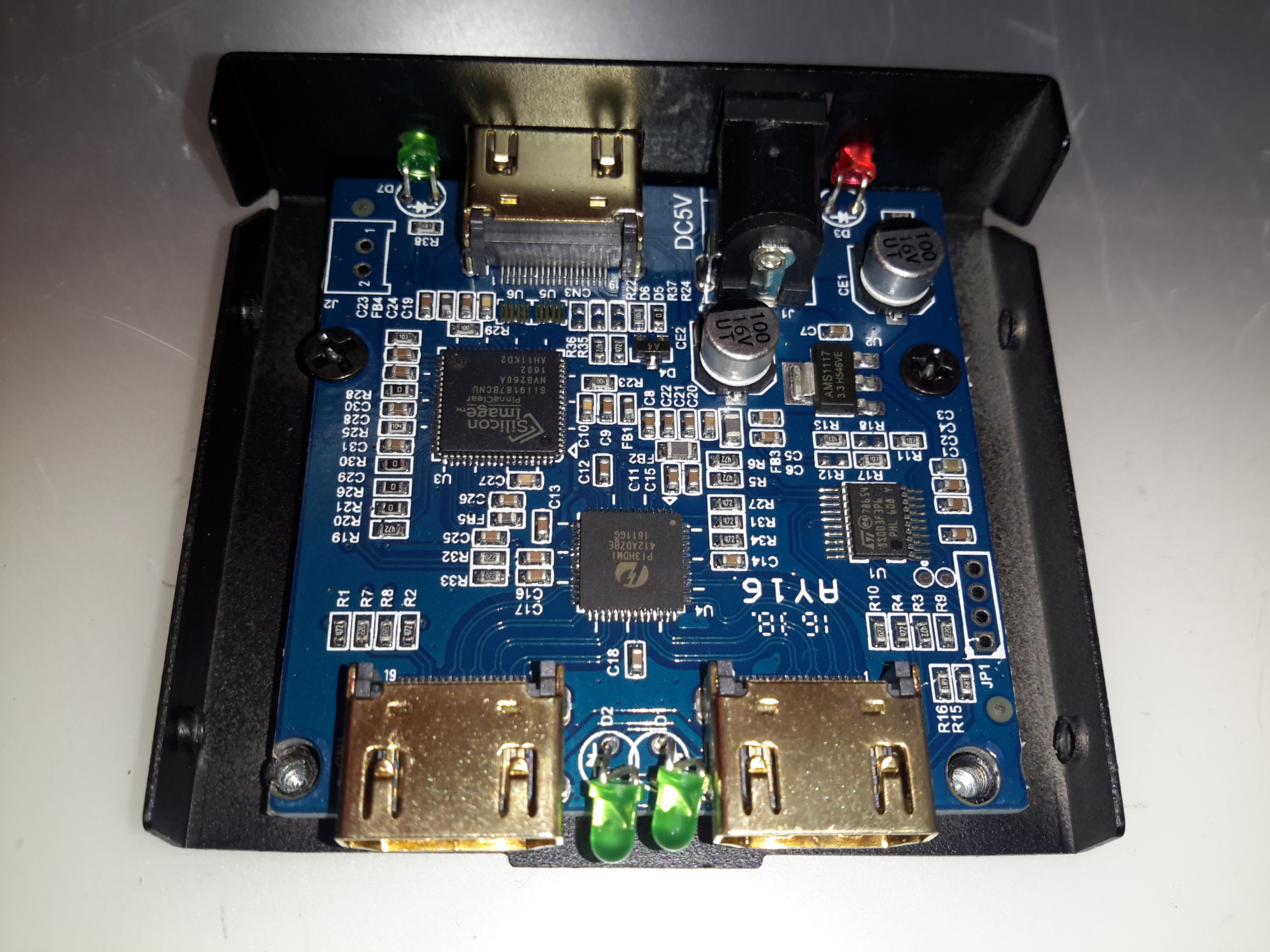
Time for another random teardown, a signal splitter for HDMI. These units are available very cheap these days on eBay. This one splits the incoming signal into two to drive more than one display from the same signal source.
Main PCB
The stamped alloy casing comes apart easily with the removal of a few screws. The PCB inside is rather densely packed with components.
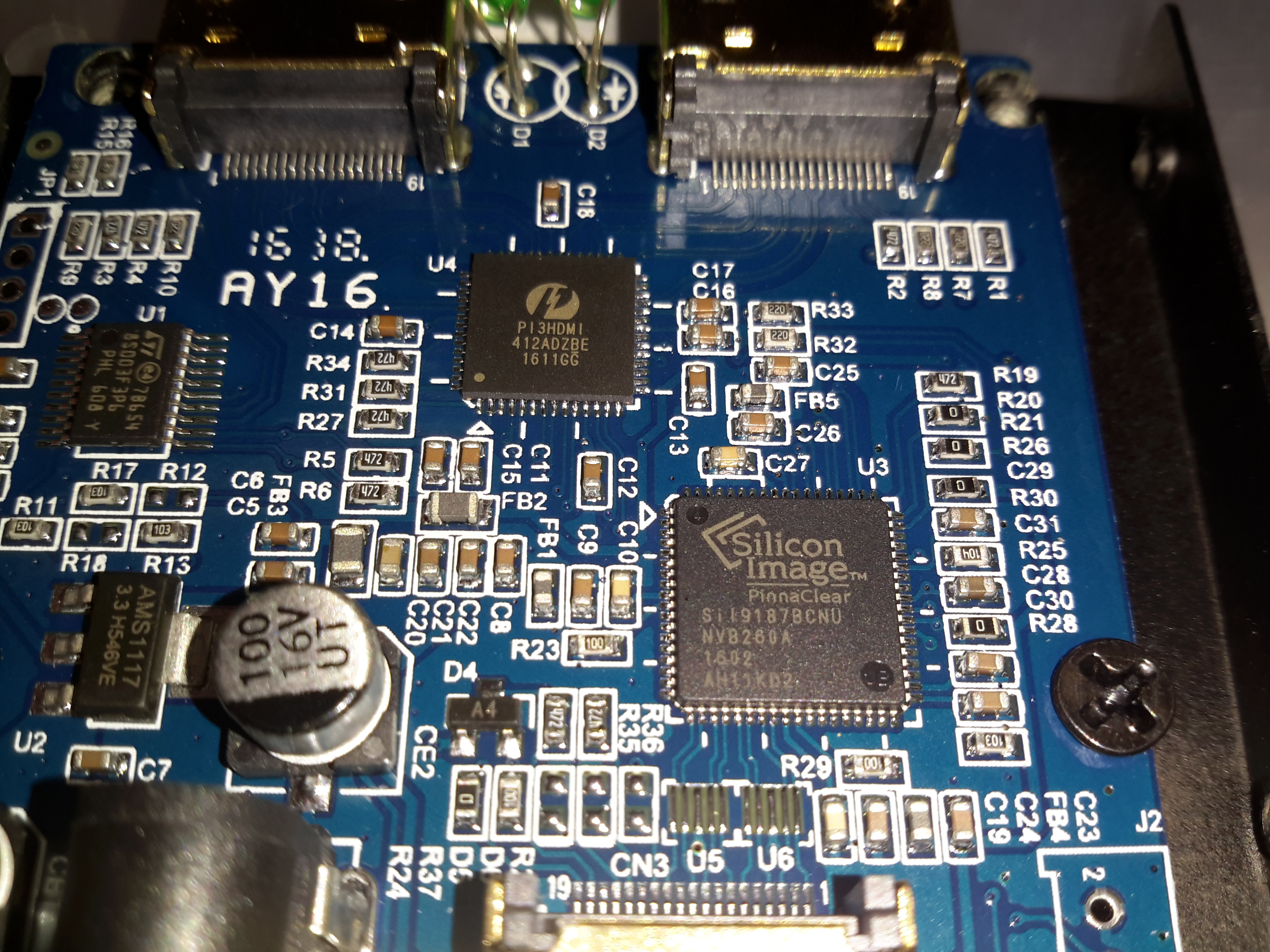
Chipset
The main IC on the incoming signal is a Silicon Image Sil9187B HDMI Port Processor, with a single input & 4 outputs. In this case the chip is used as a repeater to amplify the incoming signal. the signal path then gets fed into a Pericom PI3HDMI412 HDMI Demux, which then splits the signal into two for the output ports.
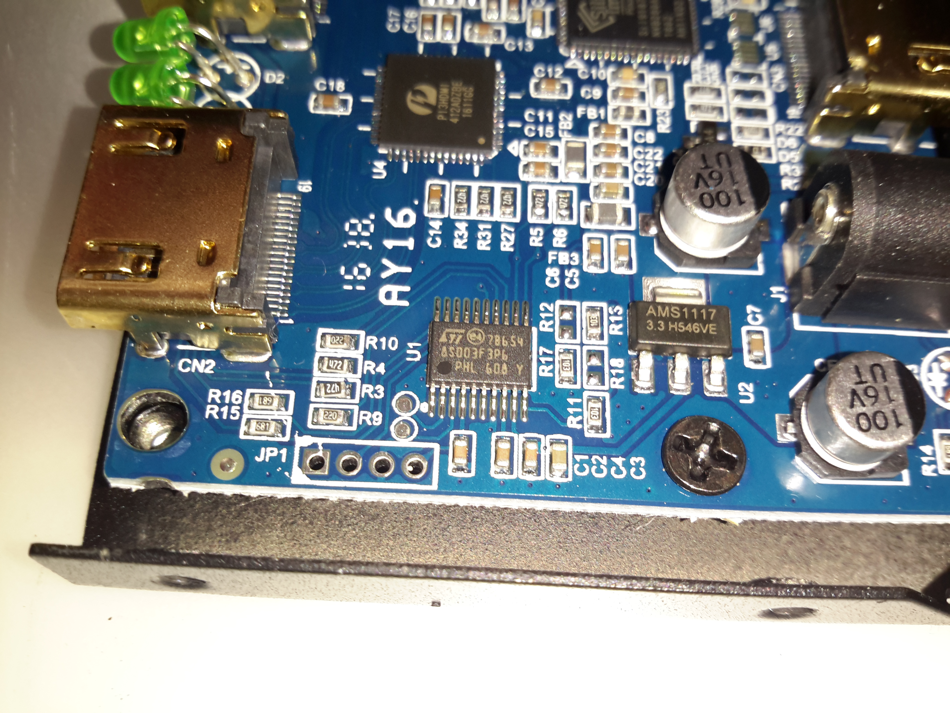
Microcontroller
The main pair of ICs processing the video signals are controlled over I²C, with this STM32 microcontroller. The 4 pads to the lower left are for the STLink programmer. The main 3.3v power rail is provided by the LM1117 linear regulator on the right.
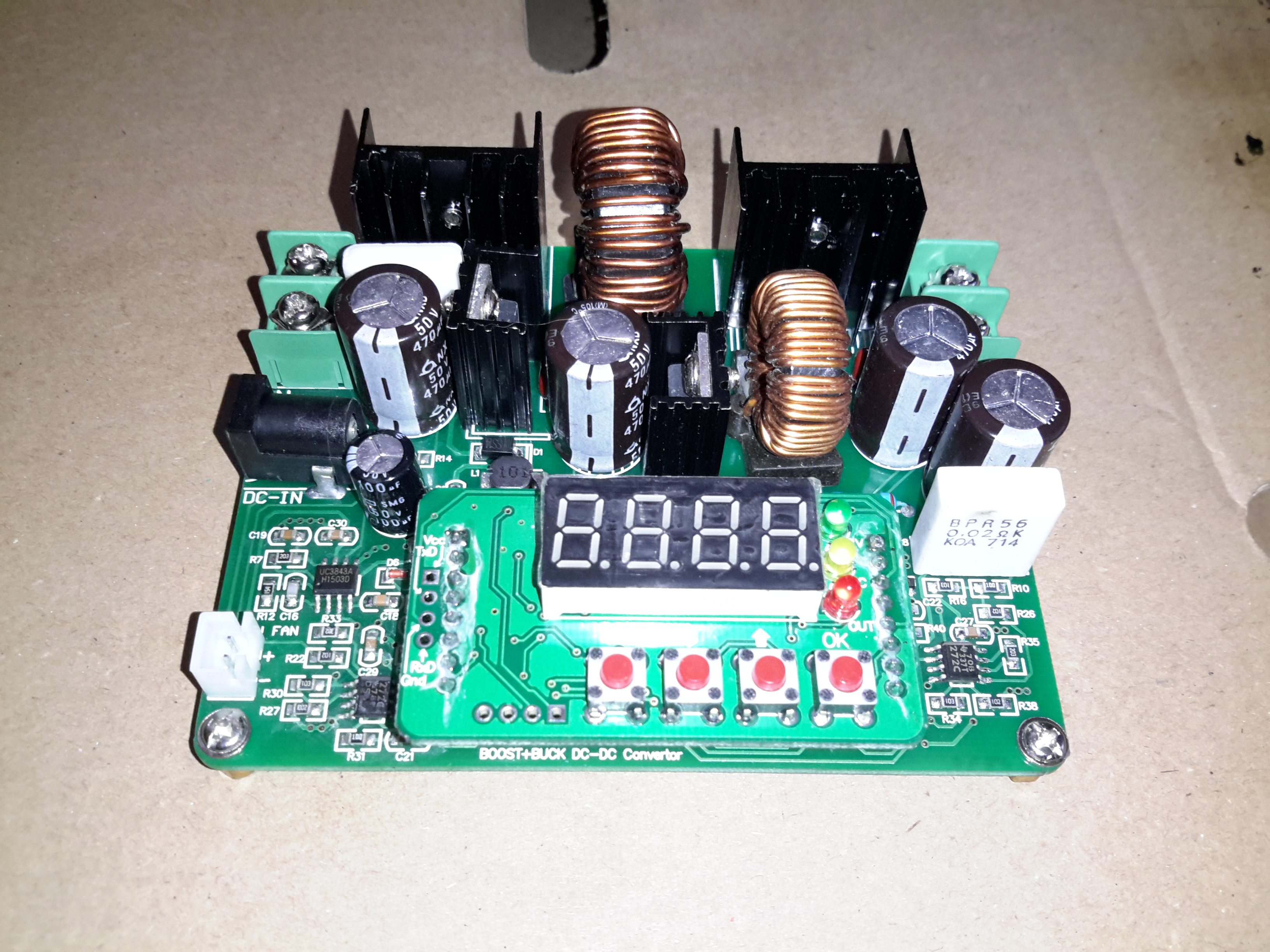
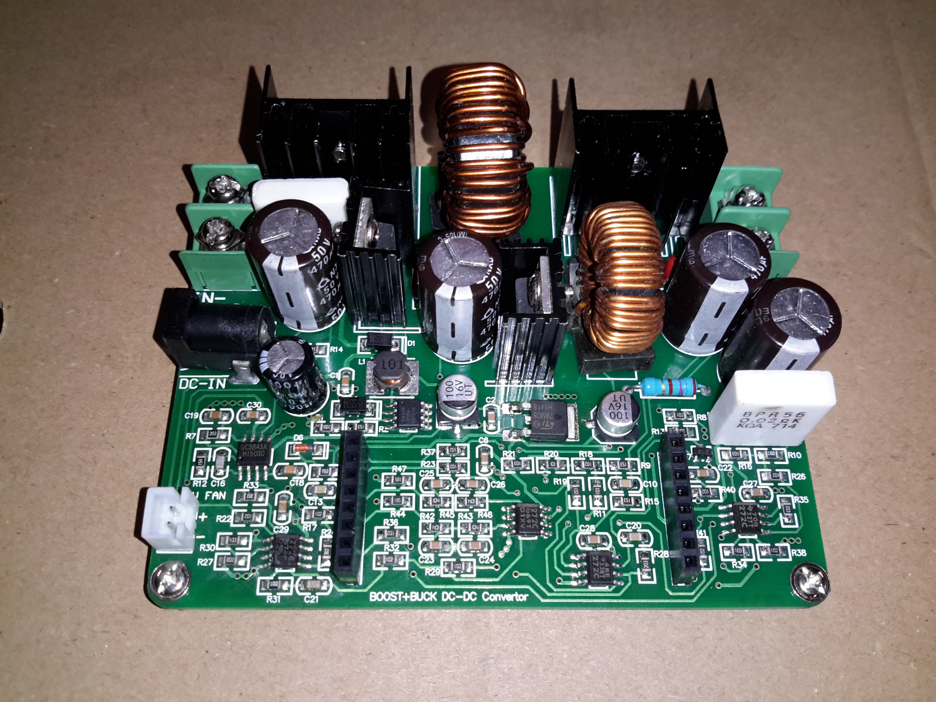
Here’s a useful buck-boost DC-DC converter from eBay, this one will do 36v DC at 6A maximum output current. Voltage & current are selected on the push buttons, when the output is enabled either the output voltage or the output current can be displayed in real time.
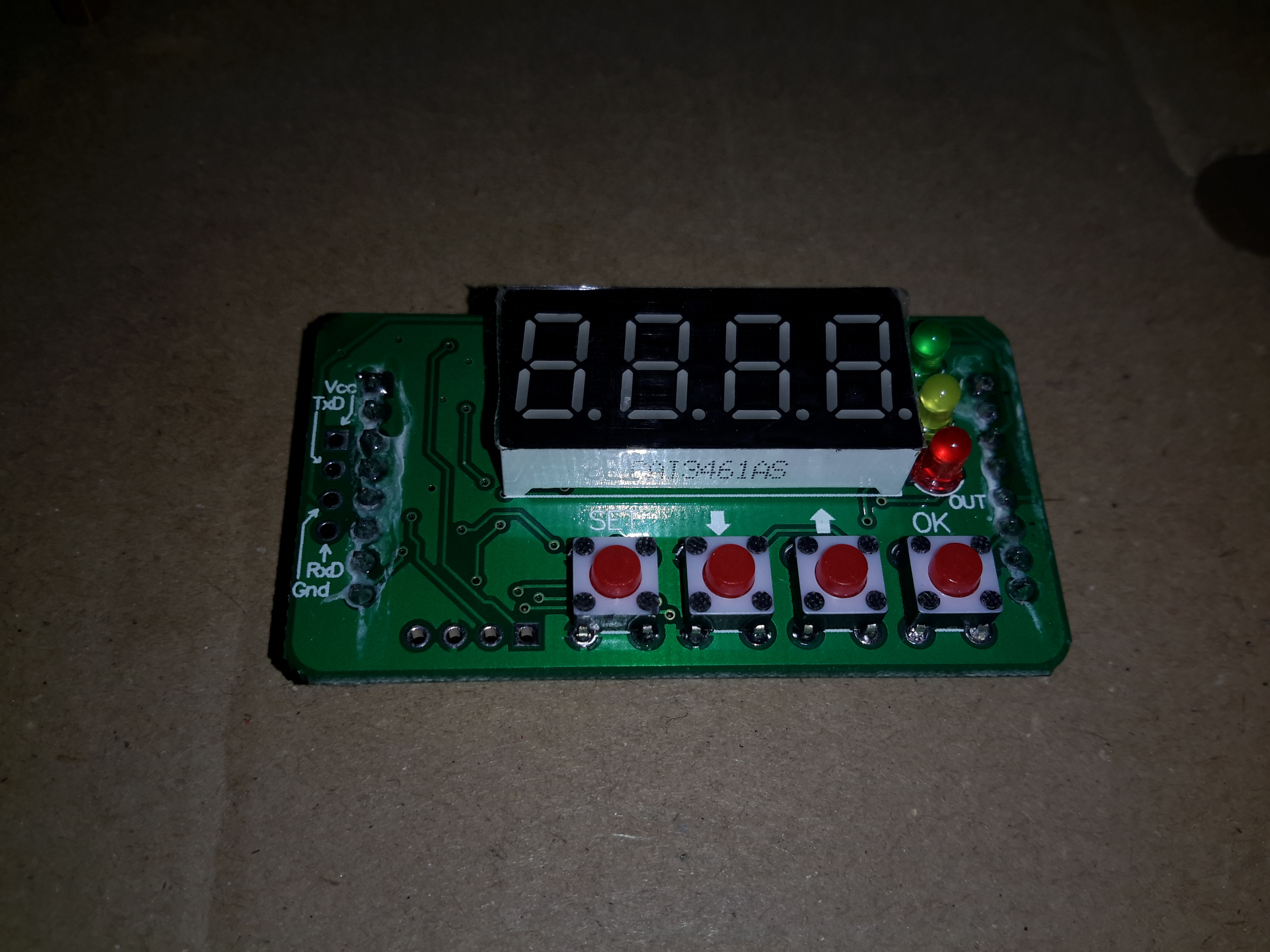
Display PCB
Here’s the display PCB, which also has the STM32 microcontroller that does all the magic. There appears to be a serial link on the left side, I’ve not yet managed to get round to hooking it into a serial adaptor to see if there’s anything useful on it.
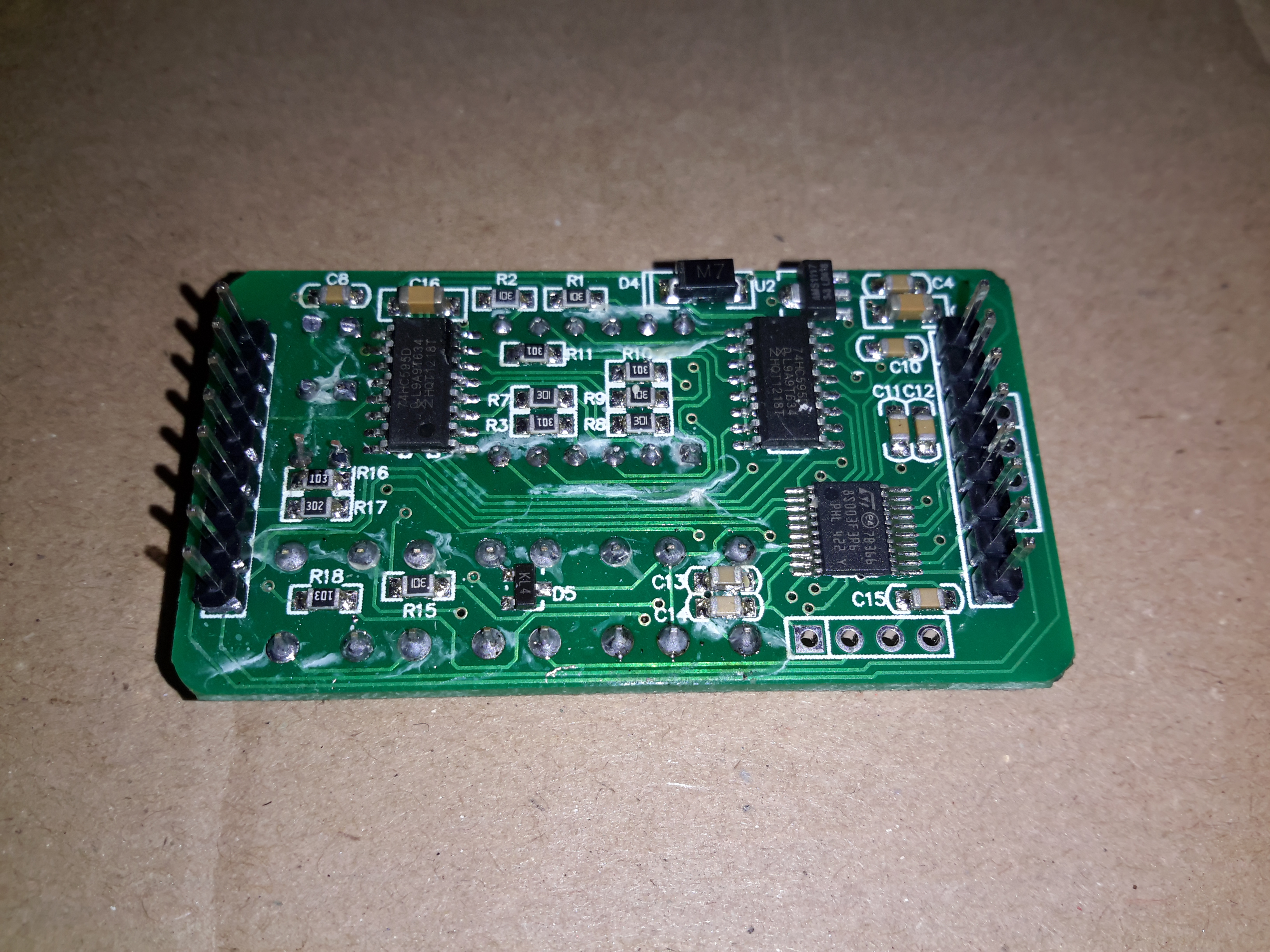
Display Drive & Microcontroller
The bottom of the board holds the micro & the display multiplexing glue logic.
Main PCB
Not much on the mainboard apart from the large switching inductors & power devices. There’s also a SMPS PWM controller, probably being controlled from the micro.
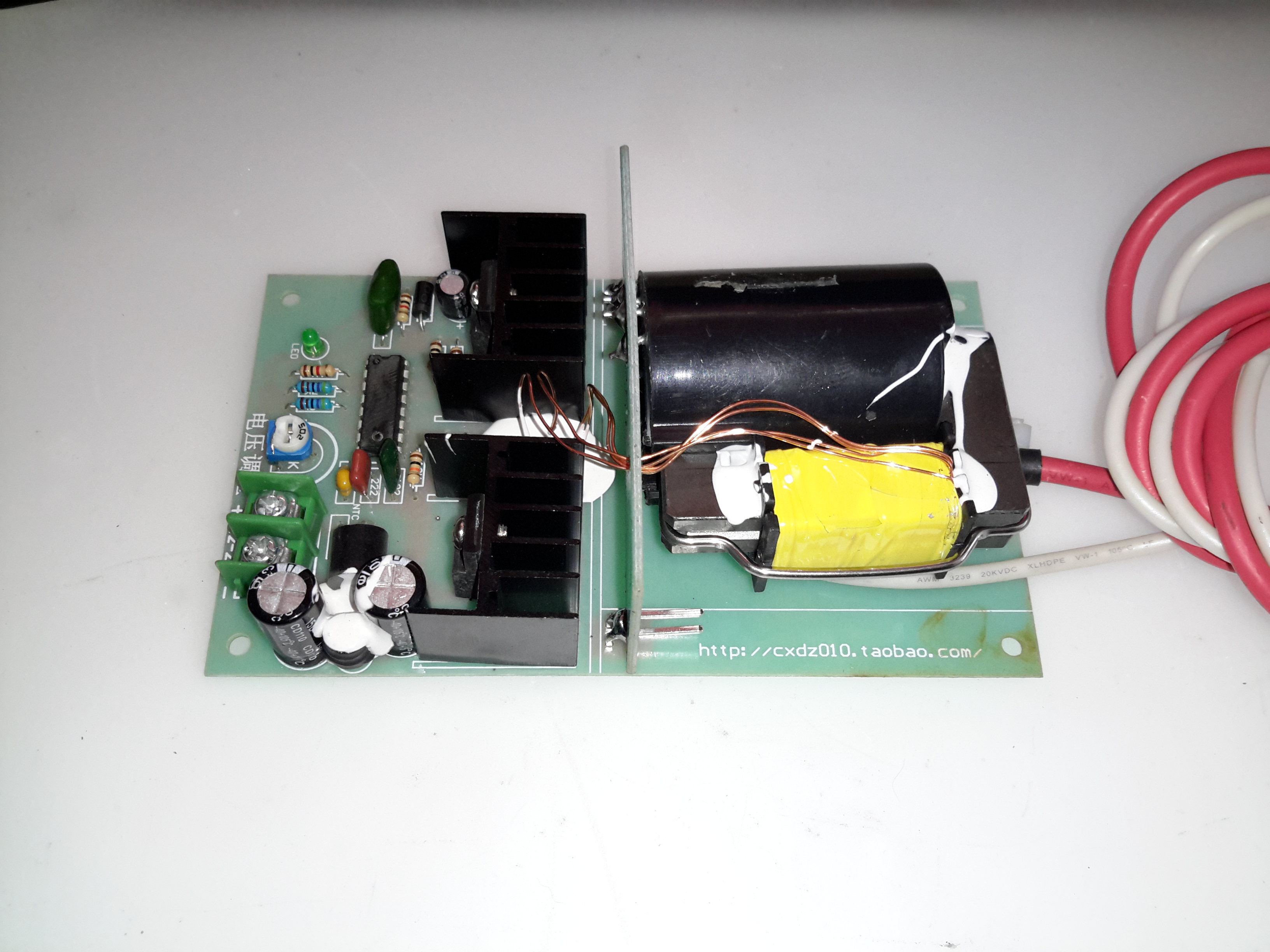
I have found myself needing some more in the way of High Voltage supplies of late, with the acquisition of the new He-Ne laser tubes, so I went trawling eBay for something that would be suitable to run these tubes. (I currently only have a single He-Ne laser PSU brick, and they’re notoriously hard to find & rather expensive).
This supply is rated at 1kV-10kV output, at 35W power level. Unfortunately this supply isn’t capable of sustaining the discharge in a large He-Ne tube, the impedance of the supply is far too high. Still, it’s useful for other experiments.
The flyback-type transformer clearly isn’t a surplus device from CRT manufacture, as there are very few pins on the bottom, and none of them connect to the primary side. The primary is separately wound on the open leg of the ferrite core.
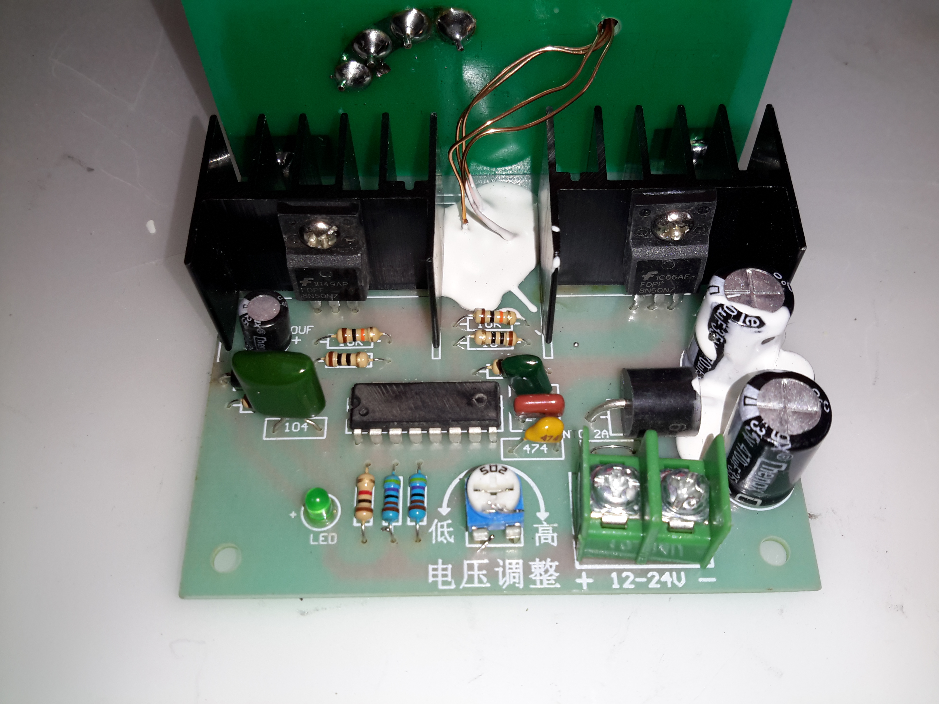
Drive Electronics
The drive electronics are pretty simple, there’s a controller IC (with the number scrubbed off – guessing it’s either a 556 dual timer or a SMPS controller), a pair of FDP8N50NZ MOSFETs driving the centre-tapped primary winding.
The drive MOSFETs aren’t anything special in this case: they’re rated at 500v 8A, 850mΩ on resistance. This high resistance does make them get rather hot even with no load on the output, so for high power use forced-air cooling from a fan would definitely be required.
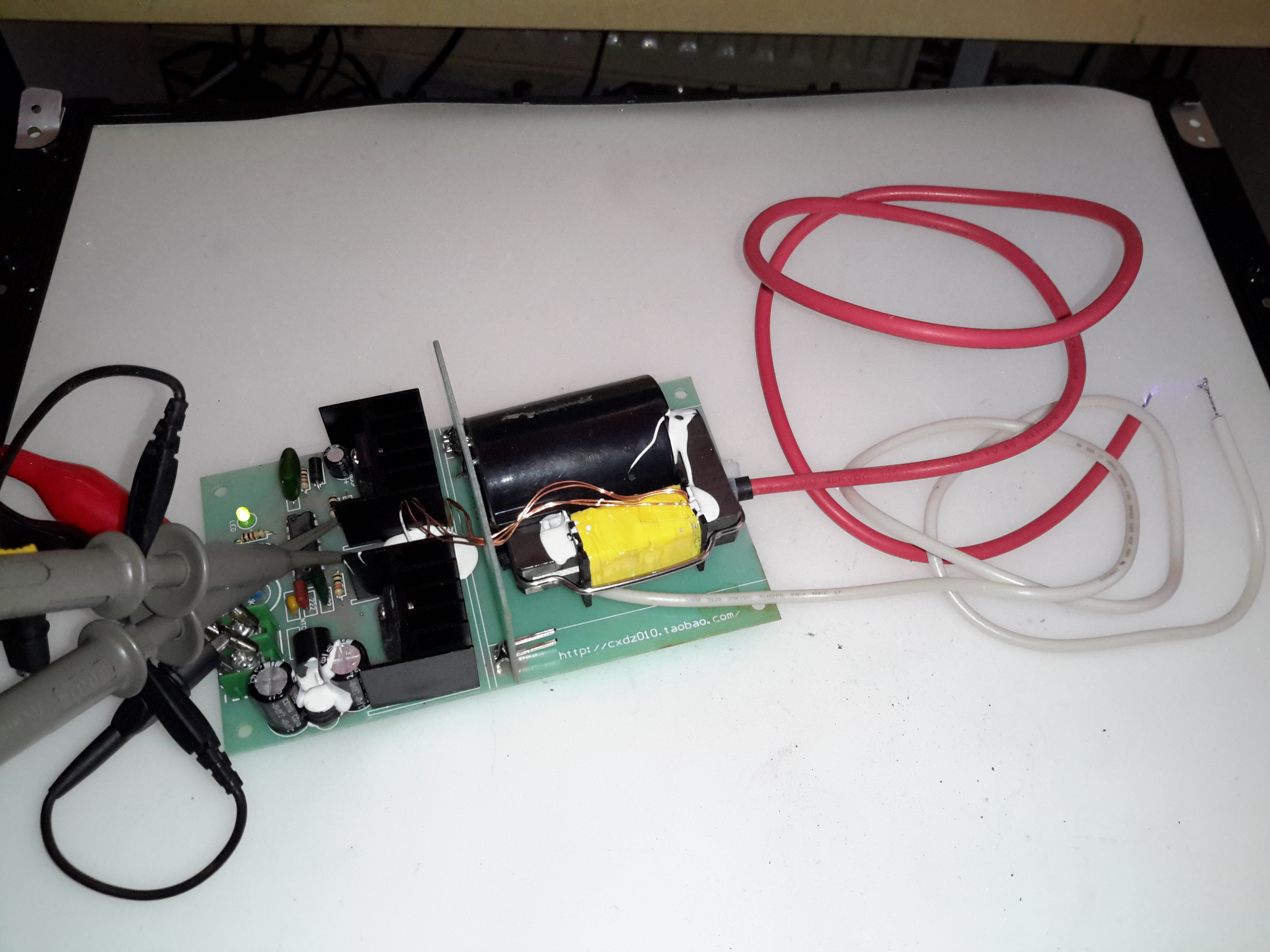
Test Setup
Here’s the supply on test, I’ve got the scope probes connected to the gate resistors of the drive MOSFETs.
Waveforms
On the scope the primary switching waveforms can be seen. The FETs operate in push-pull mode, there’s a bit of a ring on the waveform, but they’re pretty nice square waves otherwise.
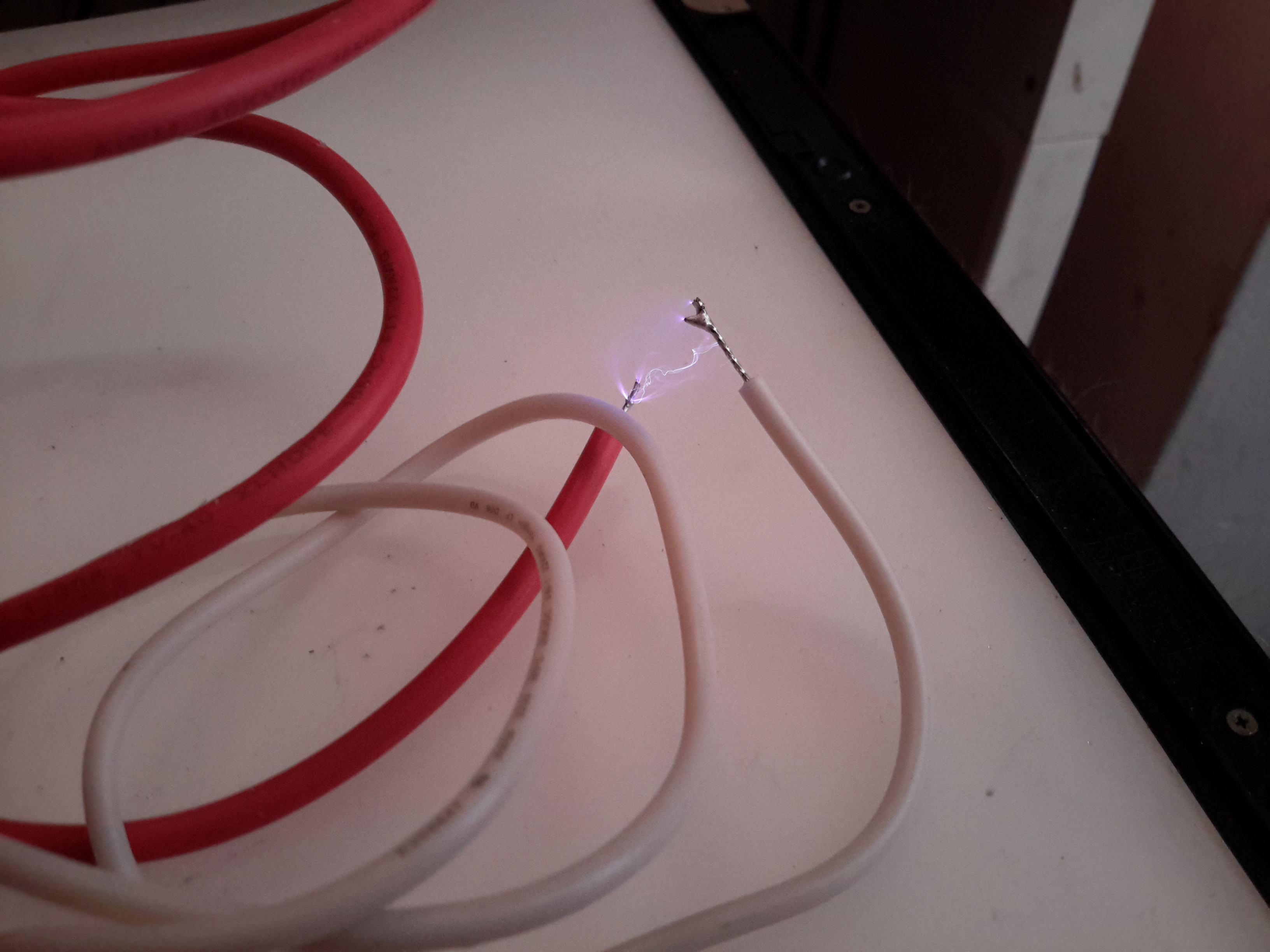
Arc
At maximum power on 12v input, about 25mm of gap is possible with an arc.
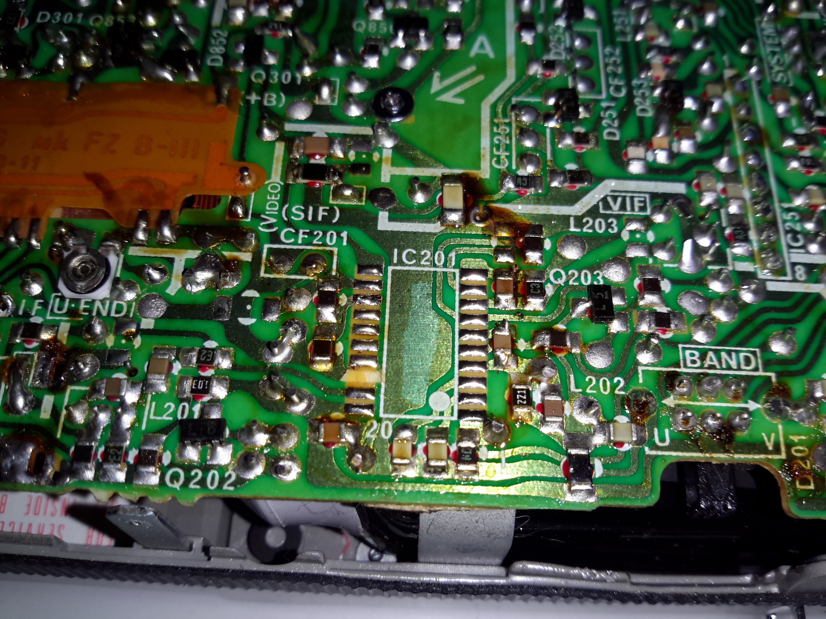
Hacking the Sony FD-20 to accept a composite input is easy – the tuner receives the RF transmission, produces an IF, this is then fed into IC201, a Mitsubishi M51364P Video IF Processor. The VIF IC then separates out the composite video signal, which is output on Pin 13 (in photo above, left side, 3rd pin from the top). The audio is separated out & sent via Pin 11 to the Audio IF processor.
In the above photo, the VIF IC has been removed from the board with hot air, as it was interfering with the signal if left in place. The RF tuner was also desoldered & removed. Unfortunately I managed to mangle a pad, which is the ground pin for the VIF IC. This isn’t much of an issue though, as an identical signal ground is available, just to the left of the IC.
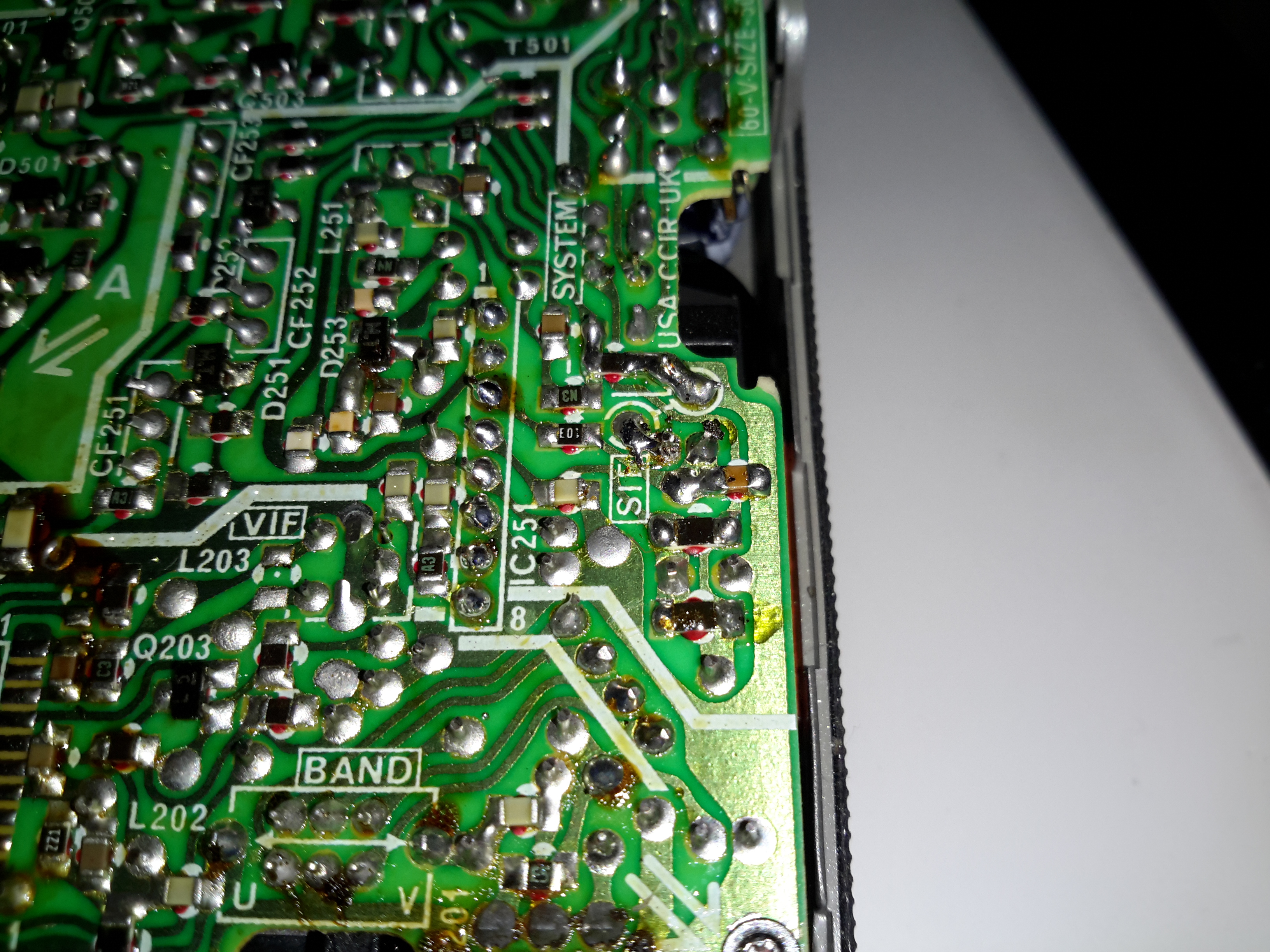
Audio Input
The audio can be tapped into in a similar way, the circled pad in the centre of the photo marked SIF is the place, this is the output of the Audio IF processor to the audio amplifier. The Audio IF processor didn’t interfere with the injected signal, so it was left in place.
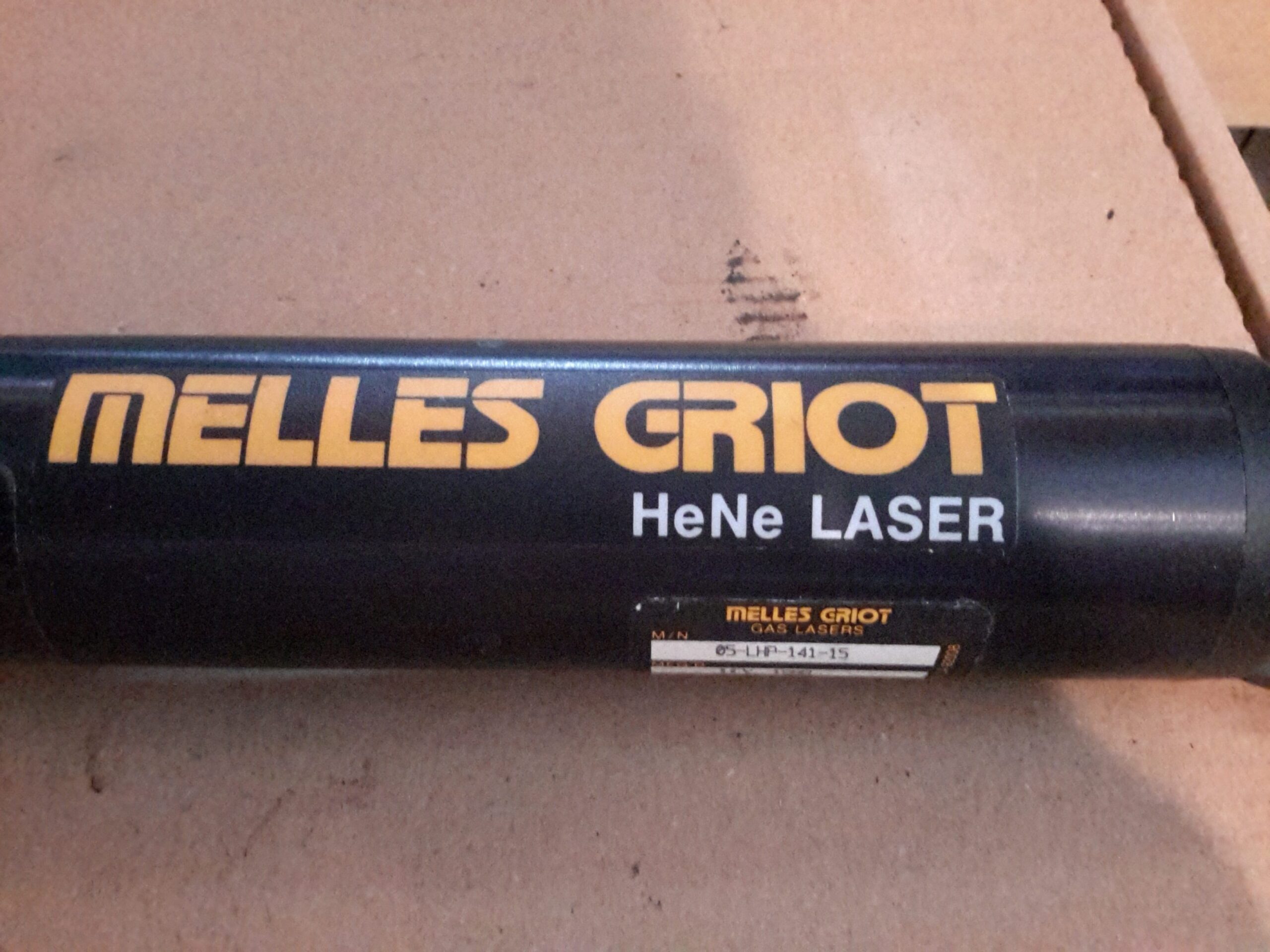
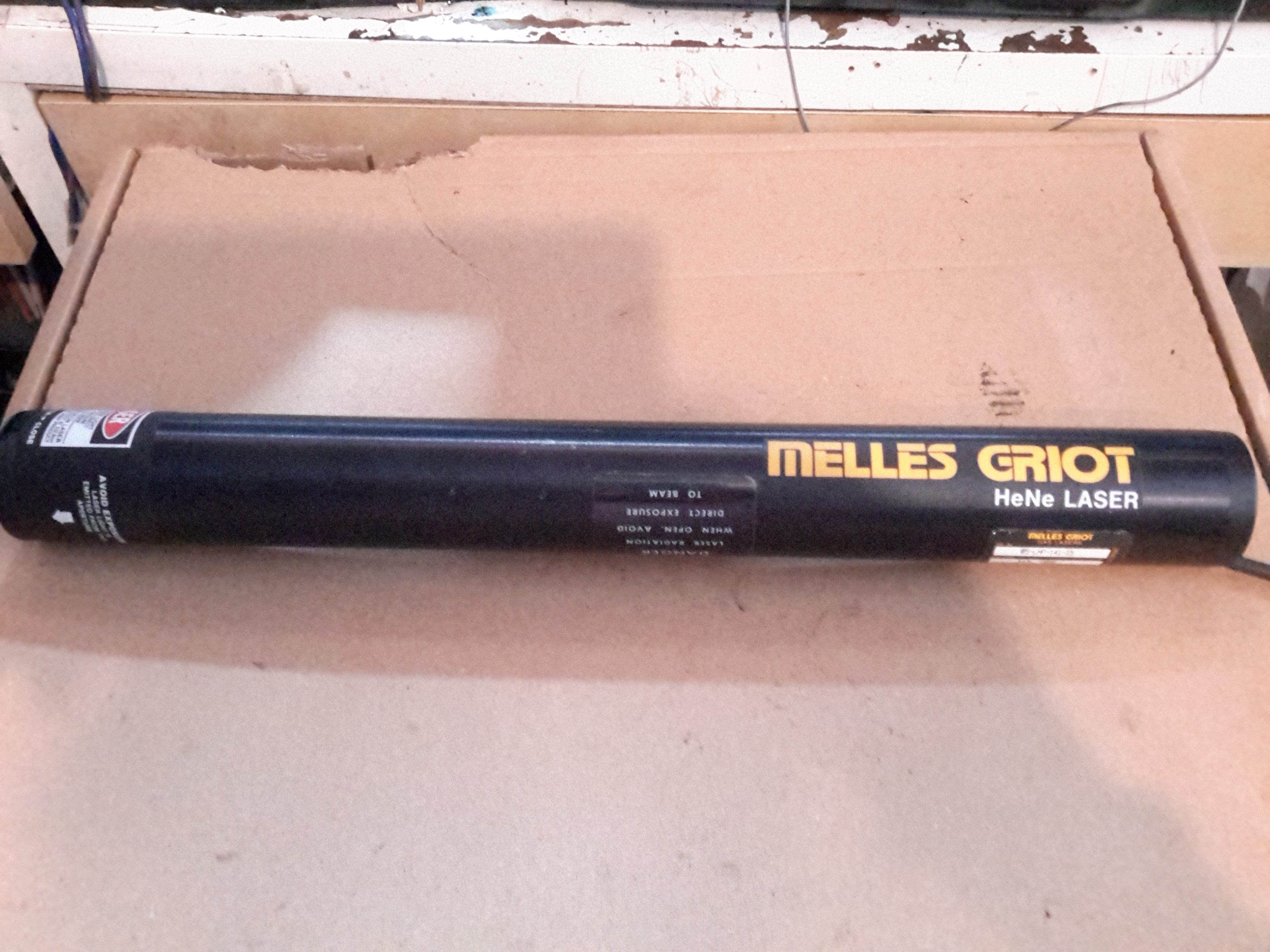
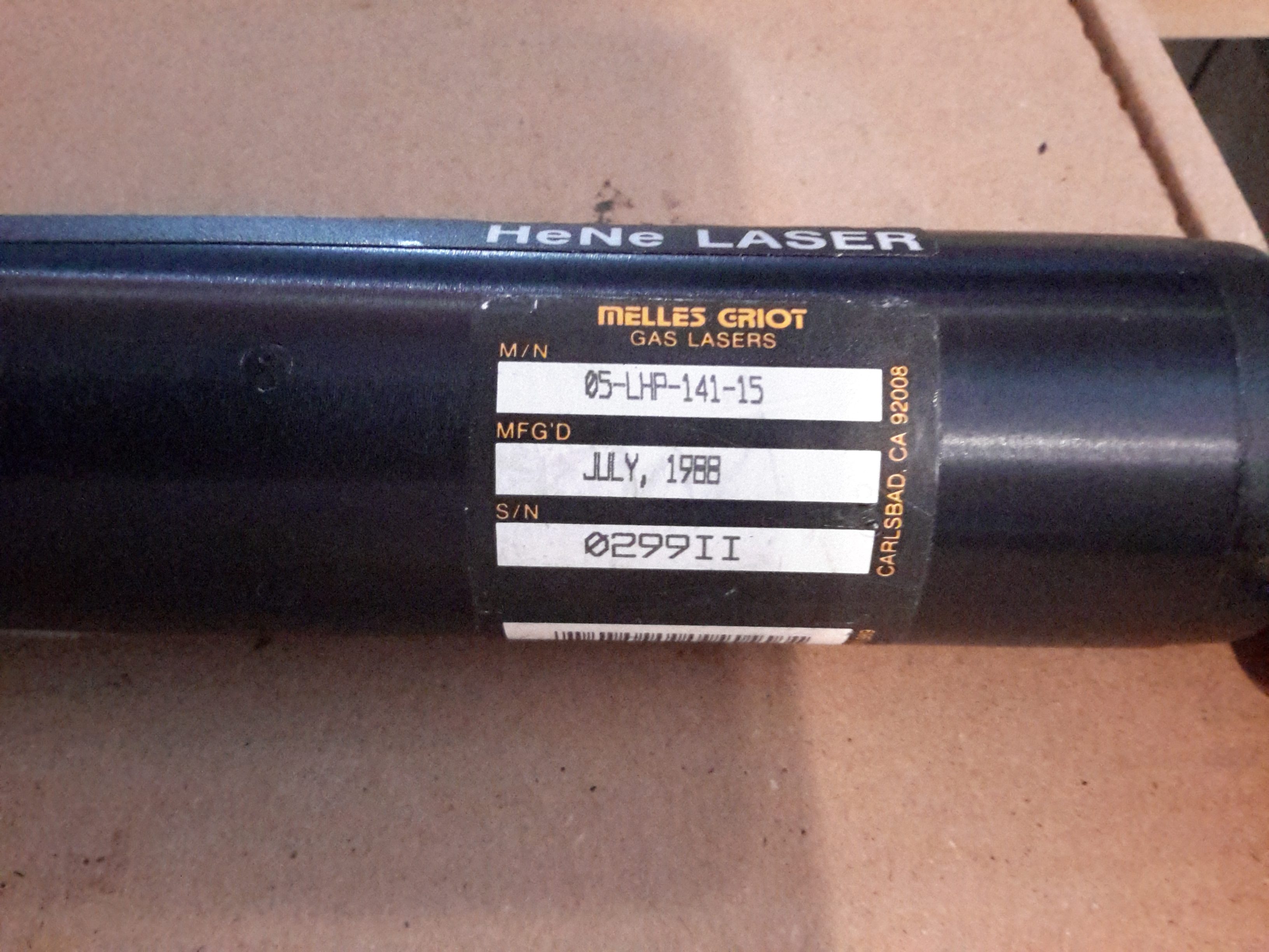
Looking through eBay recently I came across a great deal on some Helium-Neon laser heads from Melles Griot. While definitely not new, these gas lasers are extremely long-lasting & I figured the tubes inside would make a nice addition to my laser collection. Doing some searching on the model number, these heads are rated at an optical output of 4mW, but depending on how much milage is on the tubes, the output may be a bit higher.
Data Label
I got a pair of the heads, this one was manufactured in July 1988, the other March 1989.
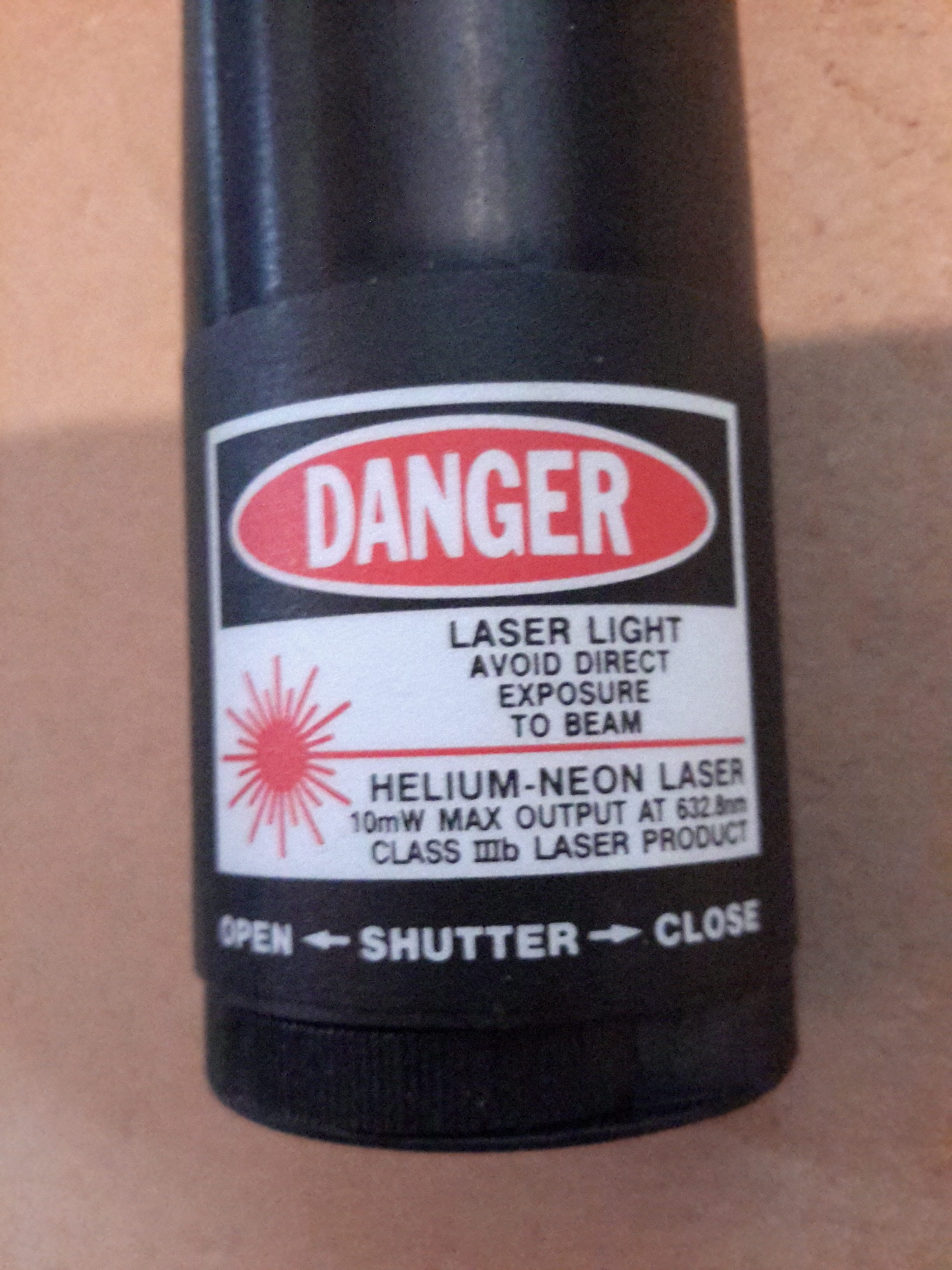
OC End / Classification Label
The OC end of the head has the laser classification label & the beam shutter. Once I’d tested the laser heads to make sure they survived the post intact, I set at extracting the plasma tubes from the aluminium housings.
The end caps are fibre-reinforced plastic & are secured with epoxy resin, so some heating & brute force released the caps from the housing, giving access to the laser tube itself.
Glue Holes
The laser tube is secured in these heads by hot glue – this was squirted into the housing via two rows of holes around the ends. (Some are secured with RTV silicone, which is substantially more difficult to remove).
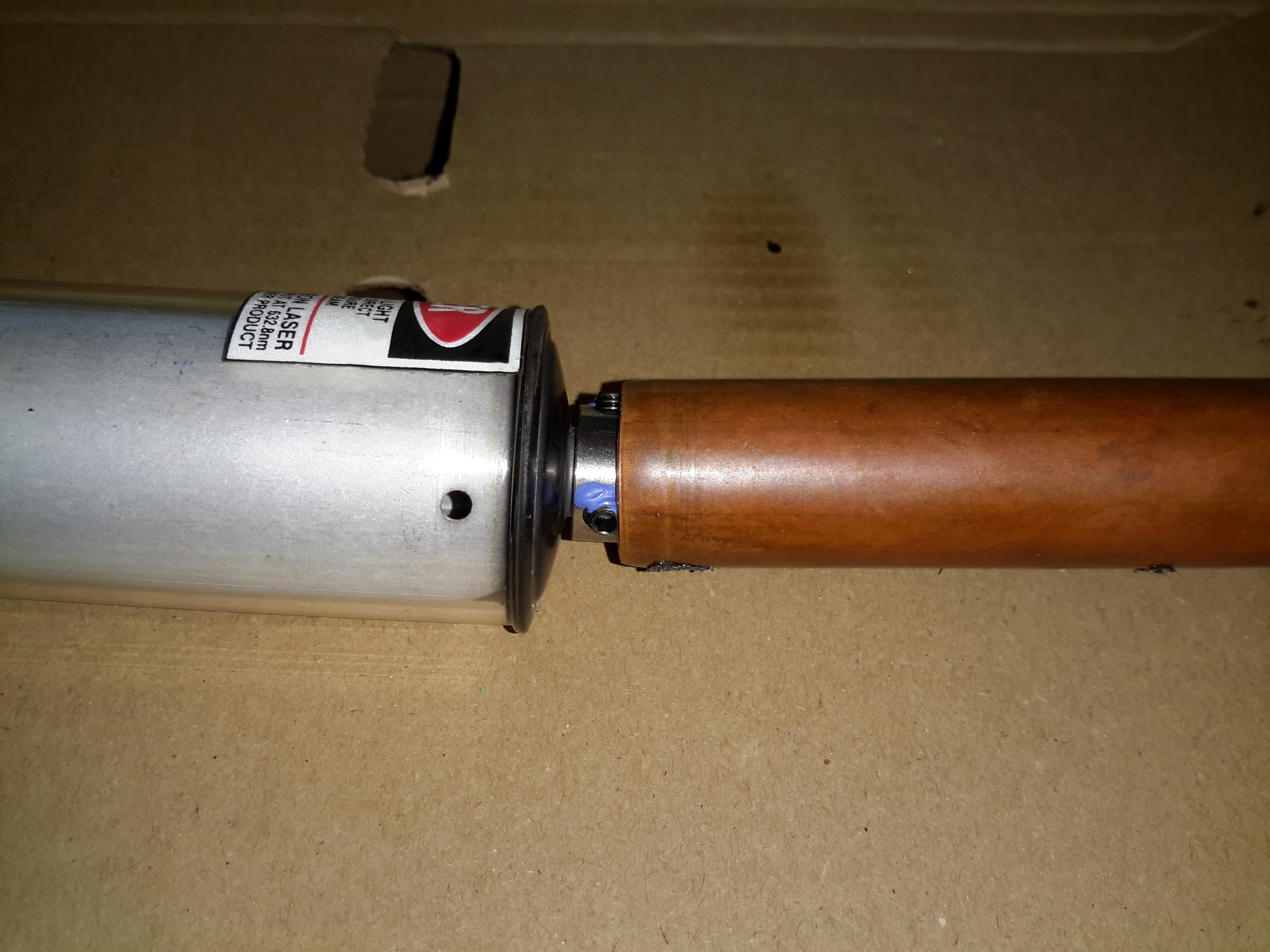
Copper Tube
I’ve no photos of the actual extraction process as it’s difficult enough as is without at least 5 hands. A heat gun was used to warm up the housing until the glue melted enough to slide the tube out of the housing. Since everything was hot at this stage, a piece of copper tubing (above), was slipped over the OC mirror mount, so I could push the tube out of the housing while the glue was soft. This also protected the mirror from damage while the tube was being removed.
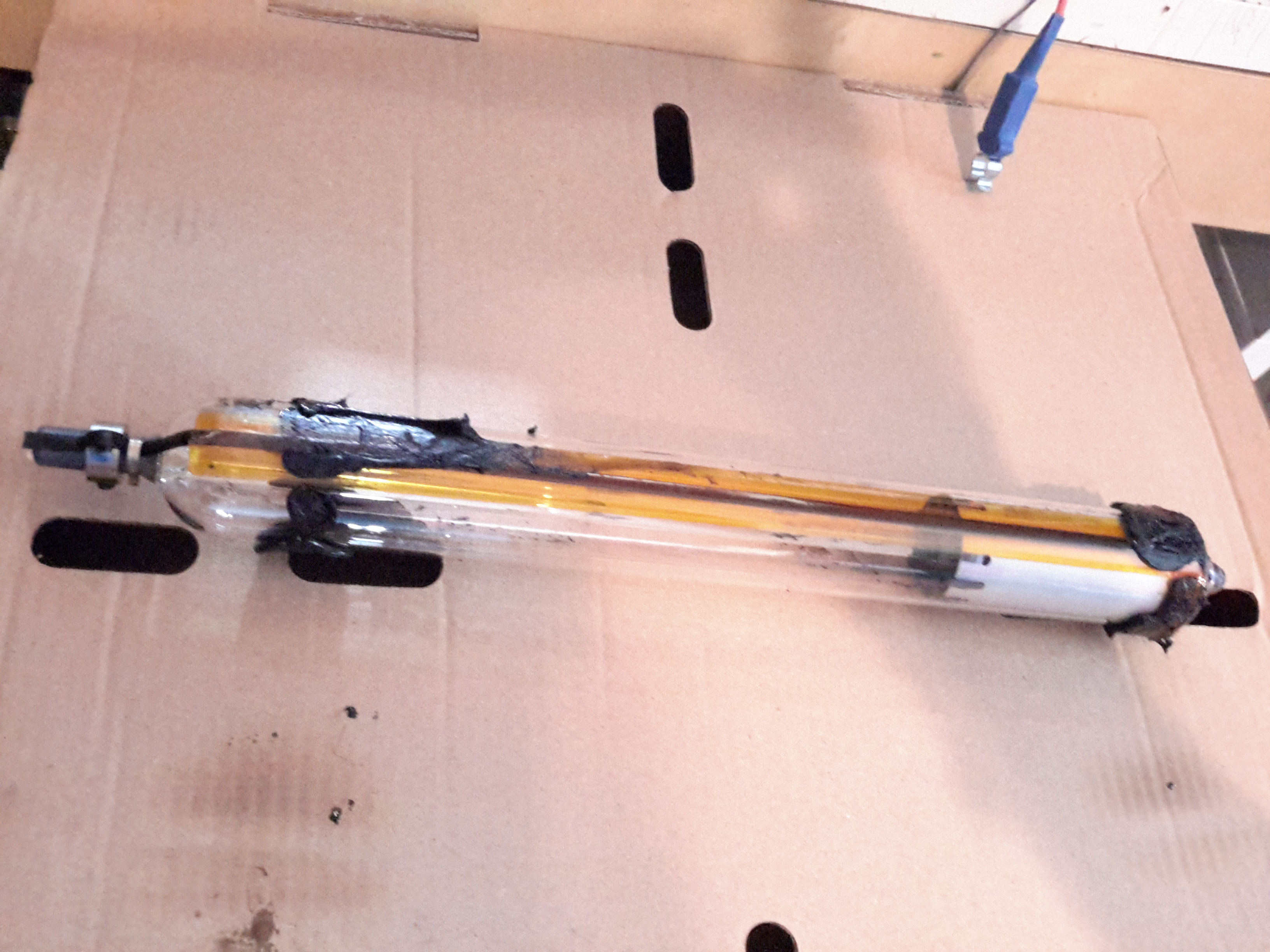
Extracted Tube
After a few minutes of gentle pushing while keeping the housing hot, the tube was released! It’s still pretty well covered in the remains of the hot glue, but this is easily removed once the tube cools down to room temperature with Isopropanol. The line of Kapton tape running down the tube to the cathode end is insulating a start tape electrode, which is supposed to make the laser strike faster on power-up. Instead of being metal though, the electrode appears to be a carbon-loaded plastic tape.
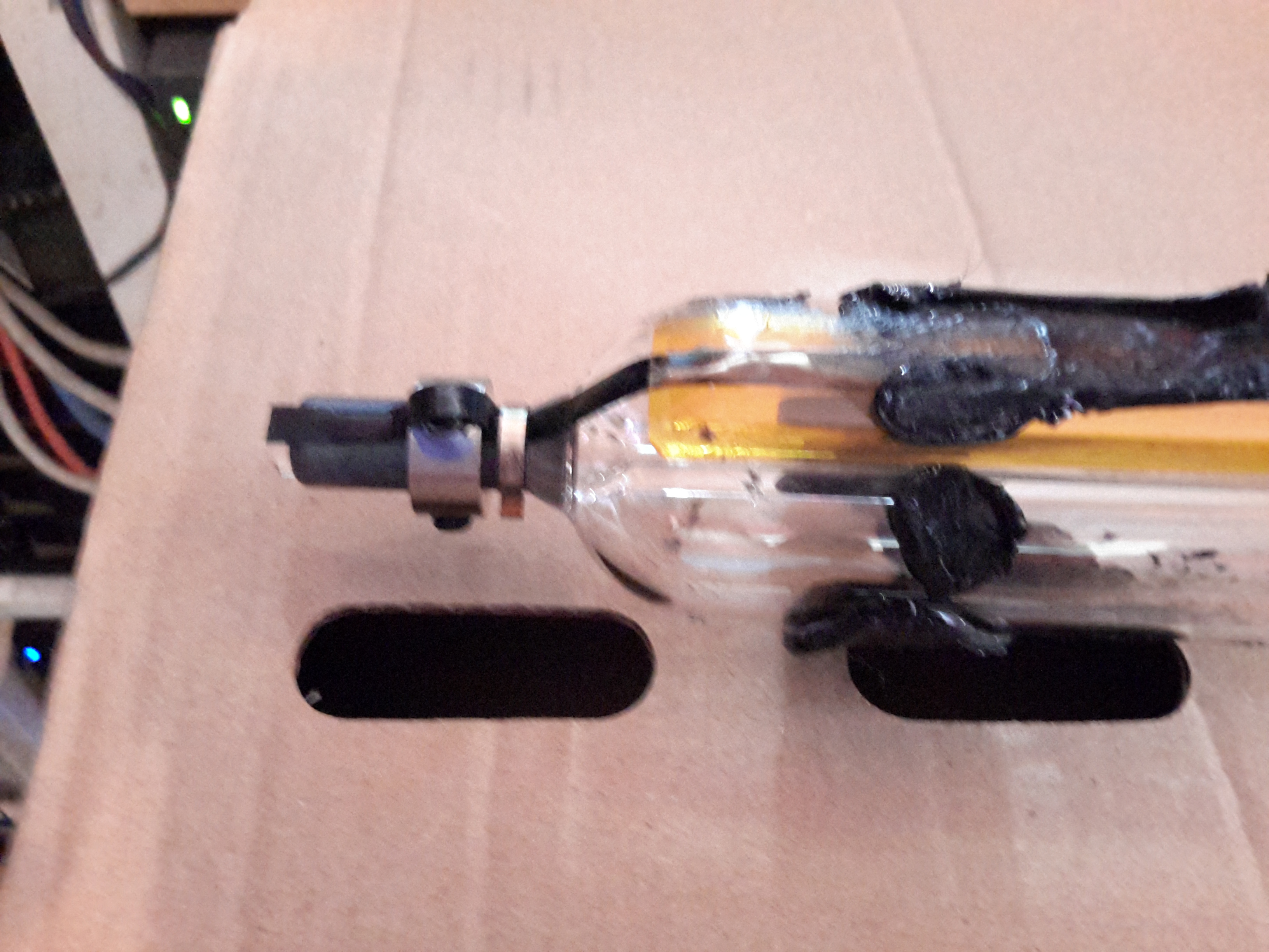
Start Tape & Adhesive
Here’s the HR end of the tube, which also serves as the high voltage anode electrode. The start tape is clipped onto the mirror mount, but all this will be removed.
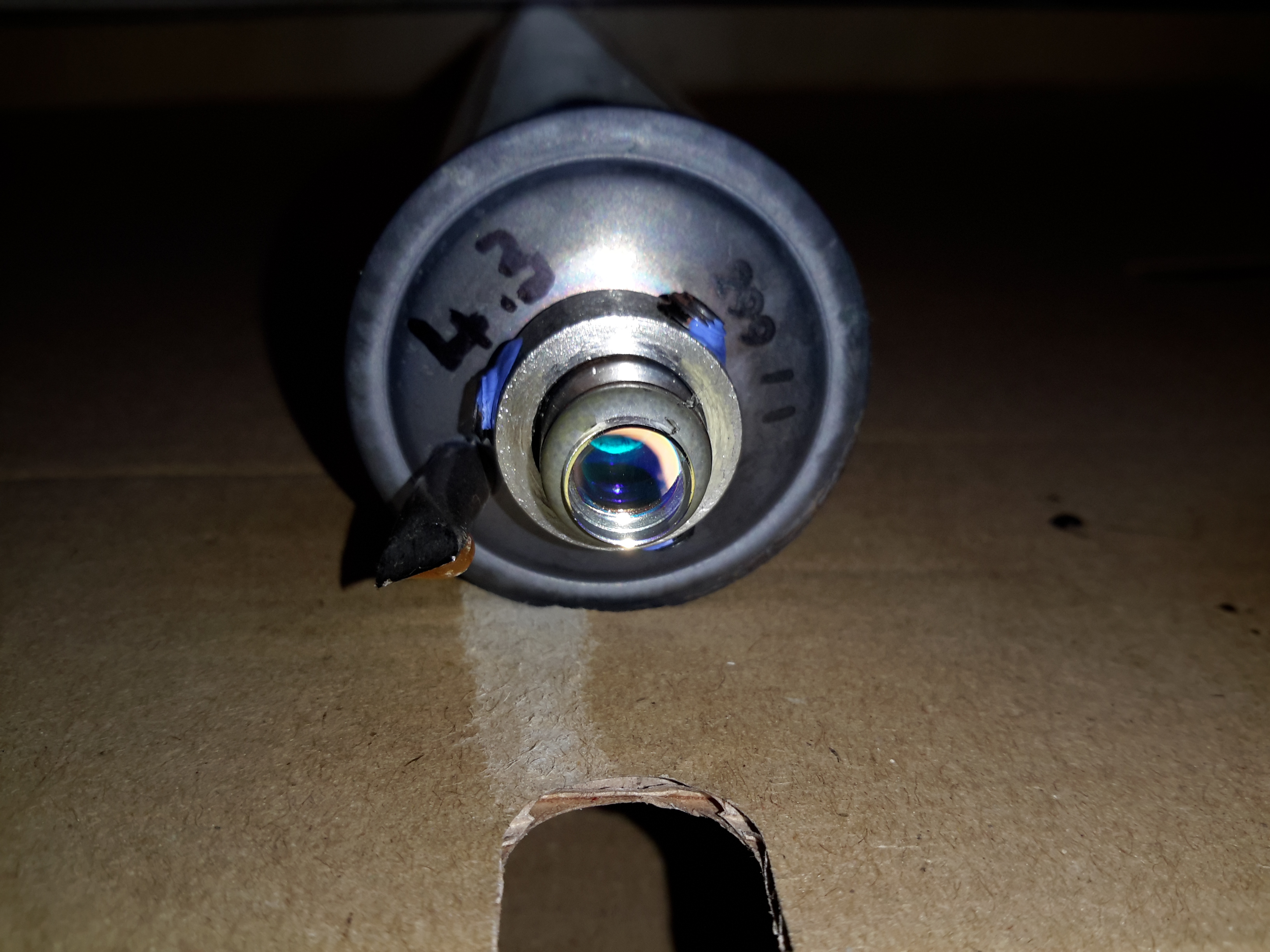
OC End
The OC end of the laser, where the beam emerges. What I think is the mW rating of the tubes is written on the end cap, probably from when the tubes were manufactured.
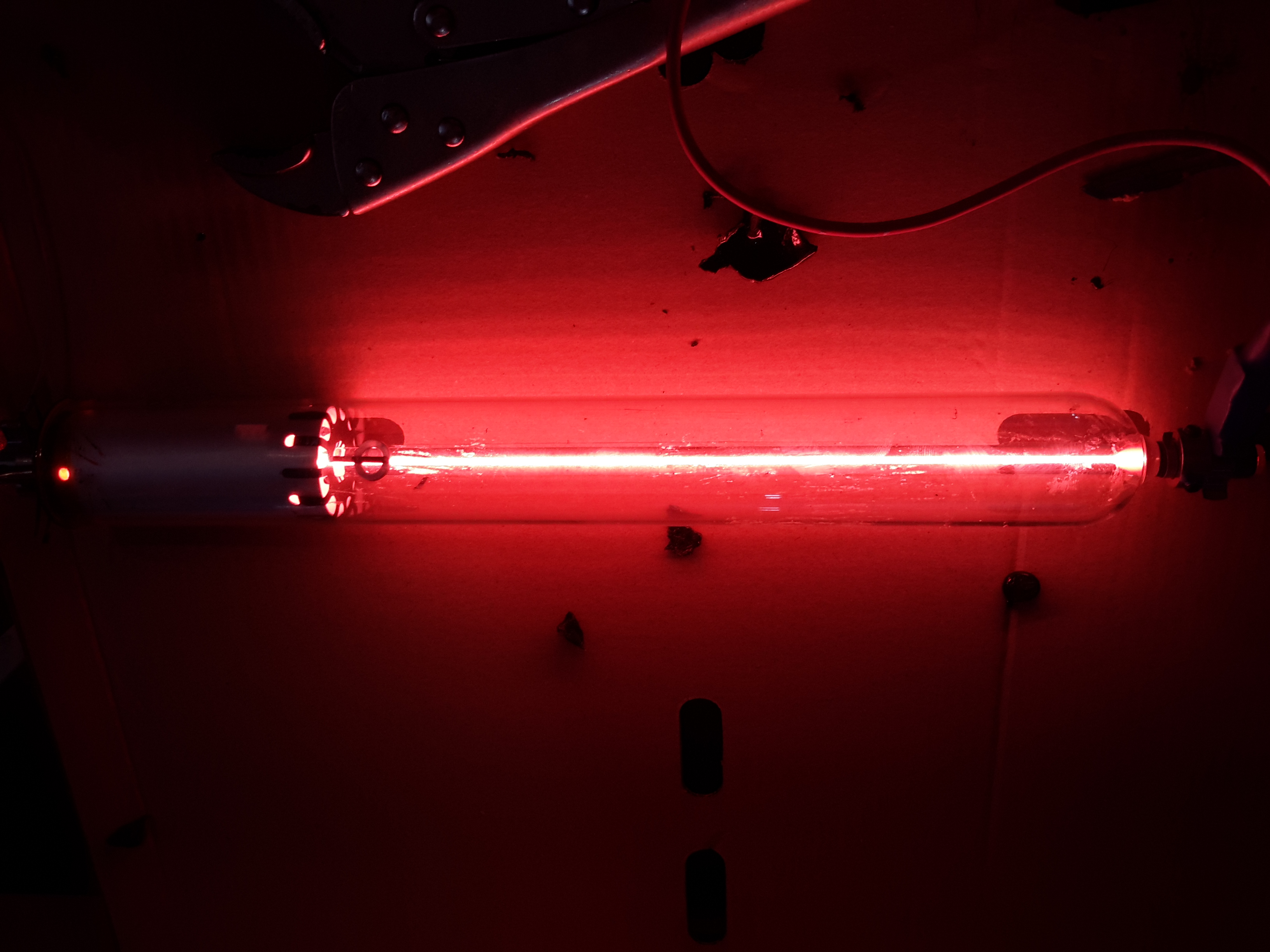
Tube Energized
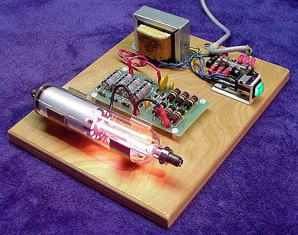
Applying power from a He-Ne laser PSU confirmed the tube still works!
Power for a He-Ne laser is provided by a special high voltage power supply and consists of two parts (these maximum values depend on tube size – a typical 1 to 10 mW tube is assumed):
Operating voltage of 1,000 to 3,000v DC at 3 to 8mA.Like most low current discharge tubes, the He-Ne laser is a negative resistance device. As the current *increases* through the tube, the voltage across the tube *decreases*. The incremental magnitude of the negative resistance also increases with decreasing current.
Starting voltage of 5 to 12 kV at almost no current.In the case of a He-Ne tube, the initial breakdown voltage is much greater than the sustaining voltage. The starting voltage may be provided by a separate circuit or be part of the main supply.Often, you may find a wire or conductive strip running from the anode or ballast resistor down to a loop around the tube in the vicinity of the cathode. (Or there may be a recommendation for this in a tube spec sheet.) This external wire loop is supposed to aid in starting (probably where a pulse type starter is involved). There may even be some statistical evidence suggesting a reduction in starting times. I wouldn’t expect there to be much, if any, benefit when using a modern power supply but it might help in marginal cases. But, running the high voltage along the body of the tube requires additional insulation and provides more opportunity for bad things to happen (like short circuits) and may represent an additional electric shock hazard. And, since the strip has some capacitance, operating stability may be impaired. I would probably just leave well enough alone if a starting strip is present and the laser operates without problems but wouldn’t install one when constructing a laser head from components.
With every laser I’ve seen using one of these strips, it has either had virtually or totally no effect on starting OR has caused problems with leakage to the grounded cylinder after awhile. Cutting away the strip in the vicinity of the anode has cured erratic starting problems in the latter case and never resulted in a detectable increase in starting time.
With a constant voltage power supply, a series ballast resistor is essential to limit tube current to the proper value. A ballast resistor will still be required with a constant current or current limited supply to stabilize operation. The ballast resistor may be included as part of a laser head but will be external for most bare tubes. (The exceptions are larger Spectra-Physics He-Ne lasers where the ballast resistors are also inside a glass tube extension, electrically connected but sealed off from the main tube.In order for the discharge to be stable, the total of the effective power supply resistance, ballast resistance, and tube (negative) resistance must be greater than 0 ohms at the operating point. If this is not the case, the result will be a relaxation oscillator – a flashing or cycling laser!
Power supply polarity is important for He-Ne tubes. Electrical behaviour may be quite different if powered with incorrect polarity and tube damage (and very short life) will likely be the result from prolonged operation.
The positive output of the power supply is connected to a series ballast resistor and then to the anode (small) electrode of the He-Ne tube. This electrode may actually be part of the mirror assembly at that end of the tube or totally separate from it. The distance from the resistors to the electrode should be minimized – no more than 2 or 3 inches.
The negative output of the power supply is connected to the cathode (large can) electrode of the He-Ne tube. This electrode may be electrically connected to the mirror mount at that end of the tube but is a separate aluminium cylinder that extends for several inches down the tube. CAUTION: Some He-Ne tubes use a separate terminal for the cathode and sometimes the anode as well, not the mirror mount(s). Powering one of these via the mirror mounts may result in lasing but will also result in tube damage.
Note: He-Ne tube starting voltage is lower and operating voltage is higher when powered with reverse polarity. With some power supply designs, the tube may appear to work equally well or even better (since starting the discharge is easier) when hooked up incorrectly. However, this is damaging to the anode electrode of the tube (and may result in more stress on the power supply as well due to the higher operating voltage) and must be avoided (except possibly for a very short duration during testing).
Every He-Ne tube will have a nominal current rating. In addition to excessive heating and damage to the electrodes, current beyond this value does not increase laser beam intensity. In fact, optical output actually decreases (probably because too high a percentage of the helium/neon atoms are in the excited state). You can easily and safely demonstrate this behaviour if your power supply has a current adjustment or you run an unregulated supply using a Variac. While the brightness of the discharge inside the tube will increase with increasing current, the actual intensity of the laser beam will max out and then eventually decrease with increasing current. (This is also an easy way of determining optimal tube current if you have not data on the tube – adjust the ballast resistor or power supply for maximum optical output and set it so that the current is at the lower end of the range over which the beam intensity is approximately constant.) Optical noise in the output will also increase with excessive current.
The efficiency of the typical He-Ne laser is pretty pathetic. For example, a 2 mW HeNe tube powered by 1,400 V at 6mA has an efficiency of less than 0.025%. More than 99.975% of the power is wasted in the form of heat and incoherent light (from the discharge)! This doesn’t even include the losses of the power supply and ballast resistor.
A few He-Ne lasers – usually larger or research types – have used a radio frequency (RF) generator – essentially a radio transmitter to excite the discharge. This was the case with the original He-Ne laser but is quite rare today given the design of internal mirror He-Ne tubes and the relative simplicity of the required DC power supply.
For accurate measurements, you’ll need an optical instrument such as a monochromator or spectrophotometer or optical spectrum analyzer. But to simply see the complexity of the discharge spectrum inside the bore of a He-Ne laser tube, it’s much easier and cheaper.
(Spectra for various elements and compounds can be easily found by searching the Web. The NIST Atomic Spectra Database has an applet which will generate a table or plot of more spectral lines than you could ever want.)
Instant Spectroscope for Viewing Lines in He-Ne Discharge
It is easy to look at the major visible lines. All it takes is a diffraction grating or prism. I made my instant spectroscope from the diffraction grating out of some sort of special effects glasses – found in a box of cereal, no less! – and a monocular (actually 1/2 of a pair of binoculars).
If you missed the Kellogg’s option, diffraction gratings can be purchased from places like Edmund Scientific. You don’t need anything fancy – any of the inexpensive ‘transmission replica gratings’ on a flat rigid substrate or mounted between a pair of plane glass plates will be fine. In a pinch, a CD disc or other optical media will work but only as a reflection grating so mounting may be a problem. A spectroscope can also be made with a prism of course but a diffraction grating is likely to be less expensive and better for this application since it is much lighter and easier to mount.
The plasma tube of a bare He-Ne laser is an ideal light source since it provides its own slit as the glow discharge is confined to the long narrow capillary bore. However, this approach can also be used with other lasers as long as the beam can be focused to a spot on a wall or screen. This will produce a ‘bright spot spectra’ instead of politically correct lines but you can’t have everything. 🙂
The diffraction grating can be used by itself but the additional optics will provide magnification and other benefits for people with less than perfect eyeballs.
Glue the diffraction grating to a cardboard sleeve that can be slipped over the (or one) objective of a monocular, binocular, or small telescope – or the telephoto lens of your camera. Orient it so that the dispersion will be vertical (since your slit will be horizontal).
Operate the HeNe tube on a piece of black velvet or paper. This will result in optimum contrast. This is best done in a darkened room where the only source of light is the laser tube itself. Just don’t trip and zap yourself on the high voltage!
A diffraction grating produces several images. The zero’th order will be the original image seen straight ahead. The important ones are the first order spectra. Tip the instrument up or down to see these. The dispersion direction – order of the colours – will depend on which way it is tipped.
Any distance beyond the closest focus of your instrument will work but being further away will reduce the effective width of the ‘slit’ resulting in the ability to distinguish more closely spaced lines.
The shear number of individual spectral lines present in the discharge is quite amazing. You will see the major red, orange, yellow, and green lines as well as some far into the blue and violet portions of the spectrum and toward the IR as well.
Bright Line Spectra of Helium and Neon
All of those shown will be present as well as many others not produced by the individual gas discharges. There are numerous IR lines as well but, of course, these will not be visible.
Place a white card in the exit beam and note where the single red output line of the He-Ne tube falls relative to the position and intensity of the numerous red lines present in the gas discharge.
As an aside, you may also note a weak blue/green haze surrounding the intense main red beam (not even with the spectroscope). This is due to the blue/green (incoherent) spectral lines in the discharge being able to pass through the output mirror which has been optimized to reflect well (>99 percent) at 632.8 nm and is relatively transparent at wavelengths some distance away from these (shorter and longer but you would need an IR sensor to see the longer ones). Since it is not part of the lasing process, this light diverges rapidly and is therefore only visible close to the tube’s output mirror.
Dynamic Measurement of Discharge Spectra
The following is trivial to do if you have a recording spectrometer and external mirror He-Ne laser. For an internal mirror He-Ne laser tube, it should be possible to rock one of the mirrors far enough to kill lasing without permanently changing alignment. If you don’t have proper measuring instruments, don’t worry, this is probably in the “Gee wiz, that’s neat but of marginal practical use” department. 🙂
(From: George Werner (glwerner@sprynet.com).)
Here is an effect I found many years ago and I don’t know if anyone has pursued it further.
We had a recording spectrometer in our lab which we used to examine the incoherent light coming from the laser discharge. This spectrum when lasing was slightly different from the spectrum when not lasing, which one can expect since energy levels are redistributed. As with most detectors, ours used a chopper in the spectrometer light beam and a lock-in amplifier.
Instead of putting the chopper in the path of light going to the spectrometer, I put it in the path of the internal laser beam, so that instead of an open/closed signal going to the amplifier it was a lasing/not-lasing signal. What was recorded then was three kinds of spectrum lines: some deflected positive in the normal way, others deflected negative, and the third group were those that were unaffected by chopping, in which case when we passed over the line we only saw an increase in the noise level. Setting up such a test is easy. The hard part is interpreting the data in a meaningful way.
Other Colour Lines in Red He-Ne Laser Output
When viewing spectral lines in the actual beam of a red He-Ne laser, you may notice some very faint ones far removed from the dominant 632.8 nm line we all know and love. (This, of course, also applies to other colour He-Ne lasers.)
For He-Ne lasers, the primary line (usually 632.8 nm) is extremely narrow and effectively a singularity given any instrumentation you are likely to have at your disposal. Any other lines you detect in the output are almost certainly from two possible sources but neither is actual laser emission:
Plasma discharge – there are many strong emission lines in the actual discharge – and none of them are actually at the 632.8nm lasing wavelength! These extend from the mid-IR through the violet.Close to the output mirror, you may see some of this light seeping through especially at wavelengths in the green, blue, and violet, for which the dielectric mirrors are nearly perfectly transparent. However, such light will be quite divergent and diffuse and won’t be visible at all more than a couple of inches from the mirror.
Superradiance – As we know, He-Ne lasers can be made to operate at a variety of wavelengths other than the common 632.8nm red. The physics for these is still applicable in a red He-Ne tube but the mirrors do not have the needed reflectivity at these other wavelengths and therefore the resonator gain is too low to support true laser action. However, stimulated emission can still take place in superradiance mode – one pass down the tube and out, exiting easily for the green wavelength in particular since the dielectric mirrors are quite transparent in that region of the spectrum.The result will be a weak green beam that can sometimes be observed with a spectroscope in a very dark room room. It isn’t really quite as coherent or monochromatic as the beam from a true green He-Ne laser and probably has much wider divergence but nonetheless may be present. It may be easier to see this by using your spectroscope to view the bright spot from the laser on a white card rather than by deflecting the beam and trying to locate the green dot off to one side.Note: I have not been able to detect this effect on the short He-Ne tubes I have checked.
Since the brightness of the discharge and superradiance output should be about the same from either mirror, using the non-output end (high reflector) should prove easier (assuming it isn’t painted over or otherwise covered) since the red beam exiting from this mirror will be much less intense and won’t obscure the weak green beam.
Note that argon and krypton ion lasers are often designed for multiline output where all colours are coherent and within an order of magnitude of being equal to each other in intensity or with a knob to select an individual wavelength. Anything like this is only rarely done with He-Ne lasers because it is very difficult (and expensive) due to the low gain of the non-red lines.
For a classroom introduction to lasers, it would be nice to have a safe setup that makes as much as possible visible to the students. Or, you may just want to have a working He-Ne laser on display in your living room! Ideally, this is an external mirror laser where all parts of the resonator as well as the power supply can be readily seen. However, realistically, finding one of these is not always that easy or inexpensive, and maintenance and adjustment of such a laser can be a pain (though that in itself IS instructive).
The next best thing is a small He-Ne laser laid bare where its sealed (internal mirror) He-Ne tube, ballast resistors, wiring, and power supply (with exposed circuit board), are mounted inside a clear Plexiglas case with all parts labelled. This would allow the discharge in the He-Ne tube to be clearly visible. The clear insulating case prevents the curious from coming in contact with the high voltage (and line voltage, if the power supply connects directly to the AC line), which could otherwise result in damage to both the person and fragile glass He-Ne tube when a reflex action results in smashing the entire laser to smithereens!
A He-Ne laser is far superior to a cheap laser pointer for several reasons:
The discharge and mirrors are clearly visible permitting the lasing process to be described in detail. Compared to this, a diode laser pointer is about as exciting as a flashlight even if you are able to extract the guts.
The beam quality in terms of coherence length, monochromaticy, shape, and stability, will likely be much higher for the He-Ne laser should you also want to use it for actual optics experiments like interferometry. (However, the first one of these – coherence length – can actually be quite good for even the some of the cheap diode lasers in laser pointers.)
For a given power level, a 632.8nm He-Ne laser will appear about 5 times brighter than a 670 nm laser pointer. 635 nm laser pointers are available but still more expensive. However, inexpensive laser pointers with wavelengths between 650 and 660 nm are becoming increasingly common and have greater relative brightness.
Important: If this see-through laser is intended for use in a classroom, check with your regulatory authority to confirm that a setup which is not explicitly CDRH approved (but with proper laser class safety stickers) will be acceptable for insurance purposes.
For safety with respect to eyeballs and vision, a low power laser – 1 mW or less – is desirable – and quite adequate for demonstration purposes.
The He-Ne laser assembly from a barcode scanner is ideal for this purpose. It is compact, low power, usually runs on low voltage DC (12 V typical), and is easily disassembled to remount in a demonstration case. The only problem is that many of these have fully potted “brick” type power supplies which are pretty boring to look at. However, some have the power supply board coated with a rubbery material which can be removed with a bit of effort (well, OK, a lot of effort!).
He-Ne Tube and Power Supply
For example, this is from a hand-held barcode scanner. A similar unit was separated into its component parts:
Melles Griot He-Ne TubeHe-Ne Laser Power Supply IC-I1
The power supply includes the ballast resistors. These could easily be mounted in a very compact case (as little as 3″ x 6″ x 1″, though spreading things out may improve visibility and reduce make cooling easier) and run from a 12v DC, 1 A wall adapter. Used barcode scanner lasers can often be found for $20 or less.
An alternative is to purchase a 0.5 to 1 mW He-Ne tube and power supply kit. This will be more expensive (figure $5 to $15 for the He-Ne tube, $25 to $50 for the power supply) but will guarantee a circuit board with all parts visible.
The He-Ne tube, power supply, ballast resistors (if separate from the power supply), and any additional components can be mounted with standoffs and/or cable ties to the plastic base. The tube can be separated from the power supply if desired to allow room for labels and such. However, keep the ballast resistors as near to the tube as practical (say, within a couple of inches, moving them if originally part of the power supply board). The resistors may get quite warm during operation so mount them on standoffs away from the plastic. Use wire with insulation rated for a minimum of 10 kV. Holes or slots should be incorporated in the side panels for ventilation – the entire affair will dissipate 5 to 10 Watts or more depending on the size of the He-Ne tube and power supply.
When attaching the He-Ne tube, avoid anything that might stress the mirror mounts. While these are quite sturdy and it is unlikely that any reasonable arrangement could result in permanent damage, even a relatively modest force may result in enough mirror misalignment to noticeably reduce output power. And, don’t forget that the mirror mounts are also the high voltage connections and need to be well insulated from each other and any human contact! The best option is probably to fasten the tube in place using Nylon cable ties, cable clamps, or something similar around the glass portion without touching the mirror mounts at all (except for the power connections).
Provide clearly marked red and black wires (or binding posts) for the low voltage DC or a line cord for AC (as appropriate for the power supply used), power switch, fuse, and power-on indicator. Label the major components and don’t forget the essential CDRH safety sticker (Class II for less than 1 mW or Class IIIa for less than 5 mW).
See:
Sam’s Demo He-Ne Laser
Above, as an example (minus the Plexiglas safety cover), contructed from the guts of a surplus Gammex laser (probably part of a patient positioning system for a CT or MRI scanner). The discrete line operated power supply is simple with the HV transformer, rectifier/doubler, filter, multiplier, and ballast resistors easily identified. This would make an ideal teaching aid.
Rather than having a see-through laser that just outputs a laser beam (how boring!), consider something that would allow access to the internal cavity, swapping of optics, and modulation of beam power. OK, perhaps the truly ultimate demo laser would use a two-Brewster tube allowing for interchangeable optics at both ends, be tunable to all the He-Ne spectral lines, and play DVD movies. 🙂 We’ll have to settle for something slightly less ambitious (at least until pigs fly). Such a unit could consist of the following components:
One-Brewster He-Ne laser tube or head. This can be something similar to the Melles Griot 05-LHB-570 tube or the Climet 9048 head which contains this tube. These have a Brewster window at one end and an internal HR mirror with a 60 cm Radius of Curvature (RoC) at the other. Their total length is about 10.5 inches (260 mm).
Adjustable mirror mount with limited range to permit easy mirror tweaking but with minimal chance of getting alignment really messed up. A basic design using a pair of plates with X and Y adjustment screws and a common pivot with lock washers for the compliance springs would be adequate.
Interchangeable mirrors of RoC = 60 cm and reflectance of 98% to 99.5% (OC) and 99.999% (HR in place of OC to maximize internal photon flux). These may be salvaged from a dead 3 to 5 mW He-Ne laser tube. Those from a tube like the Spectra-Physics 084-1 would be suitable. It would be best to install the mirrors in protective cells for ease of handling.
Baseplate to mount the laser and optics with the internal HR of the one-Brewster tube/head about 60 cm from the external mirror to create a confocal cavity – about one half of which is external and accessible. An option would be to put the external mirror mount on a movable slide to allow its position to be changed easily.
Power supply with adjustable current and modulation capability. This would provide the ability to measure output power versus current and to use the laser as an optical transmitter with a solar cell based receiver.
Plexiglas box to house and protect the laser and power supply (as well as inquisitive fingers from high voltage) with part of one side open to allow access to the internal photons.
Everything needed for such a setup is readily available or easily constructed at low cost but you’ll have to read more to find out where or how as each of the components are dealt with in detail elsewhere in Sam’s Laser FAQ (but I won’t tell you exactly where – these are all the hints you get for this one!).
A system like this could conceivably be turned into an interactive exhibit for your local science museum – assuming they care about anything beyond insects and the Internet these days. 🙂 There are some more details in the next section.
Guidelines for a Demonstraton One-Brewster He-Ne Laser
The following suggestions would be for developing a semi-interactive setup whereby visitors can safely (both for the visitor and the laser) adjust mirror alignment and possibly some other parameters of laser operation. The type of one-Brewster (1-B) He-Ne laser tube like the Melles Griot 05-LHB-570. Note that the 05-LHB-570 is a wide bore tube that runs massively multi (transverse) mode with most mirrors configurations unless an intracavity aperture is added. This is actually an advantage for several reasons:
The multi-transverse mode structure is interesting in itself and provides additional options for showing how it can be controlled.
Mirror alignment is easier and the tube will lase over a much wider range of mirror orientation.
Output power is higher for its size and power requirements.
Here are some guidelines for designing an interactive exhibit:
Mount the 1-B tube in a clear plastic (Plexiglas) enclosure with some ventilation holes to allow for cooling but make sure any parts with high voltage (anode, ballast resistors if not insulated) are safely protected from the curious. Provide a small hole lined up with the Brewster window for the intracavity beam. However, even if the B-window is at the cathode-end of the tube, don’t allow it to be accessible as the first fingerprint will prevent lasing entirely.
Put the power supply in a safe place inside another clear plastic box if desired. I’d recommend controlling it with a time switch that will turn it on for perhaps 10 minutes with a push of a button. This is a tradeoff between wear from running the laser all the time and wear from repeated starts. Don’t forget the fuse!!!
Orient the tube so the B-windows is either on the side or facing down. This will minimize dust collection and permit the rig to operate for many hours or days without the need for even dusting.
Use an output mirror with an RoC from 50 cm to planar and reflectivity of 98 to 99.5 percent at 632.8 nm. The specific parameters and distance will affect the beam size, mode structure, and output power. A shorter RoC will limit the distance over which lasing will take place but will be somewhat easier to align.
Use a decent quality mirror mount like a Newport MM-1 for the output mirror. Once it’s secured, arrange for the adjustment screws to be accessible to visitors but limit the range of rotation to less than one turn and mark the location of each screw where lasing is peaked. That way, no amount of fiddling will lose lasing entirely.
The distance between the mirror and tube can be fixed or adjustable:
For a fixed location, a distance of a few inches between the laser enclosure and mirror mount is recommended. This is enough space to install an aperture or Brewster plate. Or a hand to show that the beam is only present with the resonator is complete, not just a red light inside! But, it’s short enough that alignment is still easy.
For added excitement, put the mirror mount on a precision rail to permit the distance to be varied from 0 to at least 45 cm from the B-window. Then, it will be possible to see how the mode structure changes with distance. This will depend on the RoC of the mirror as well.
Another option is to provide various things like an iris diaphragm, thin wires and/or a cross-hair, adjustable knife edge, Brewster plate that can be oriented, etc. However, some care will be needed in making these useful without a lot of hand holding.
Weatherproofing a He-Ne Laser
If you want to use a He-Ne laser outside or where it is damp or very humid, it will likely be necessary to mount the tube and power supply inside a sealed box. Otherwise, stability problems may arise from electrical leakage or the tube may not start at all. There will then be several additional issues to consider:
Heat dissipation – For a small He-Ne tube (say 1 mW), figure this is like a 10 to 15 W bulb inside a plastic box. If you make the box large enough (e.g., 3″ x 5″ x 10″), there should be enough exterior surface area to adequately remove the waste heat.
Getting the beam out – A glass window (e.g., quality microscope slide) mounted at a slight angle (to avoid multiple reflections back to the He-Ne tube output mirror) is best. However, a Plexiglas window may be acceptable (i.e., just pointing the laser at a slight angle through the plastic case). A Brewster angle window should be used only if the He-Ne tube is a linearly polarized type (not likely for something from a barcode scanner) and then the orientation and angle must be set up for maximum light transmission.
Condensation on the optics and elsewhere – This may be a problem on exposed surfaces if they are colder than the ambient conditions. Let the entire laser assembly warm up before attempting to power it up!
Effects of Magnetic Fields on He-Ne Laser Operation
If you open the case on a higher power (and longer) He-Ne laser head or one that is designed with an emphasis on precision and stability, you may find a series of magnets or electromagnetic coils in various locations in close proximity to the He-Ne tube. They may be distributed along its length or bunched at one end; with alternating or opposing N and S poles, or a coaxial arrangement; and of various sizes, styles, and strengths.
Magnets may be incorporated in He-Ne lasers for several reasons including the suppression of IR spectral lines to improve efficiency (such as it is!) and to boost power at visible wavelengths, to control its polarization, and to split the optical frequency into two closely spaced components. There are no doubt other uses as well.
The basic mechanism for the interaction of emitted light and magnetic fields is something called the ‘Zeeman Effect’ or ‘Zeeman Splitting’. The following brief description is from the “CRC Handbook of Chemistry and Physics”:
“The splitting of a spectrum line into several symmetrically disposed components, which occurs when the source of light is placed in a strong magnetic field. The components are polarized, the directions of polarization and the appearance of the effect depending on the direction from which the source is viewed relative to the lines of force.”
Magnetic fields may affect the behaviour of He-Ne tubes in several ways:
He-Ne tubes with long discharge paths will tend to amplify the (generally unwanted) IR wavelengths (probably the one at 3.39µm which is one of the strongest, if not the strongest of all lines) at the expense of the visible ones. The purpose of these magnets is to suppress spectral lines that do not contribute to the desired lasing wavelength (usually the visible red 632.8nm for these long tubes). As a result of the Zeeman Effect, if a gas radiates in a magnetic field, most of its spectral lines are split into 2 or sometimes more components. The magnitude of the separation depends on the strength of the magnetic field and as a result, if the field is also non-uniform, the spectral lines are broadened as well because light emitted at different locations will see an unequal magnetic field. These ‘fuzzed out’ lines cannot participate in stimulated emission as efficiently as nice narrow lines and therefore will not drain the upper energy states for use by the desired lines. The magnitude of the Zeeman splitting effect is also wavelength dependent and therefore can be used to control the gain of selected spectral lines (long ones are apparently affected more than short ones on a percentage basis).The Doppler-broadened gain bandwidth of neon is inversely related to wavelength. At 632.8nm (red) it is around 1.5 to 1.6 GHz; at 3,391nm (the troublesome IR line), it is only around 310MHz. A magnetic field that varies spatially along the tube will split and move the gain curves at all wavelengths equally by varying amounts depending on position. However, a, say, 100 or 200MHz split and shift of the gain curve for the 632.8nm red transition won’t have much effect, but it will effectively disrupt lasing for the 3,391nm IR transition.Without the use of magnets, the very strong neon IR line at 3.39µm would compete with (and possibly dominate over) the desired visible line (at 632.8nm) stealing power from the discharge that would otherwise contribute to simulated emission at 632.8 nm. However, the IR isn’t wanted (and therefore will not be amplified since the mirrors are not particularly reflective at IR wavelengths anyhow). Since the 3.39nm wavelength is more than 5 times longer than the 632.8 nm red line, it is affected to a much greater extent by the magnetic field and overall gain and power output at 632.8nm may be increased dramatically (25 percent or more). The magnets may be required to obtain any (visible) output beam at all with some He-Ne tubes (though this is not common).
The typical higher power Spectra-Physics He-Ne laser will have relatively low strength magnets (e.g., like those used to stick notes to your fridge) placed at every available location along the exposed bore along the sides of the L-shaped resonator frame. They will alternate N and S poles pointing toward the bore. Interestingly, on some high mileage tubes, brown crud (which might be material sputtered off the anode) may collect inside the bore – but only at locations of one field polarity (N or S, whichever would tend to deflect a positive ion stream into the wall). The crud itself doesn’t really affect anything but is an indication of long use. And on average, tubes with a lot of brown crud may be harder to start, and require a higher voltage to run, and have lower output power.
I do not know how to determine if and when such magnets are needed for long high power He-Ne tubes where they are not part of an existing laser head. My guess is that the original or intended positions, orientations, and strengths, of the magnets were determined experimentally by trial and error or from a recipe passed down from generation to generation, and not through the use of some unusually complex convoluted obscure theory. 🙂
The only thing I can suggest other than contacting the manufacturer (like any manufacturer now cares about and supports He-Ne lasers at all!) is to very carefully experiment with placing magnets of various sizes and strengths at strategic locations (or a half dozen such locations) to determine if beam power at the desired wavelength is affected. Just take care to avoid smashing your flesh or the He-Ne tube when playing with powerful magnets. Though the magnets used in large-frame He-Ne lasers with exposed bores aren’t particularly powerful, to produce the same effective field strength at the central bore of an internal mirror He-Ne tube may require somewhat stronger ones, though even these needn’t be the flesh squashing variety. And, magnets that are very strong may affect other characteristics of the laser including polarization, and starting and running voltage. Enclosing the He-Ne tube in a protective rigid sleeve (e.g., PVC or aluminium) would reduce the risk of the latter disaster, at least. 🙂 If there is going to be any significant improvement, almost any arrangement of 1 or 2 magnets should show some effect.
There may be an immediate effect when adding or moving a magnet. However, to really determine the overall improvement in (visible) output power and any reduction in the variation of output power with mode sweep, the laser should be allowed to go through several mode sweep cycles for 3.39 µm. These will be about 5.4 times the length of the mode sweep for 632.8 nm.
CAUTION: For soft-seal laser tubes in less than excellent health (i.e., which may have gas contamination), changing the magnet configuration near the cathode may result in a slow decline in output power (over several hours) which may or may not recover. I have only observed this behaviour with a single REO one-Brewster tube, but there seems to be no other explanation for the slow decline to about half the original power, and then subsequent slow recovery with extended run time after the magnets were removed entirely. Possibly simply leaving the magnets in the new configuration would have eventually resulted in power recovery, but at the time the trend was not encouraging.
“They’ve pretty much nailed the 3.39 micron problem on red He-Ne tubes these days so magnets really aren’t needed on them. Even the new green tubes don’t have much of a problem – especially since the optic suppliers have perfected the mirror coatings. All of the good green mirrors are now done with Ion Beam Sputtering (IBS), as opposed to run-of-the-mill E-Beam stuff.However, you’ll probably see a benefit from magnets to suppress the 3.39µm line on the older He-Ne tubes.”
While most inexpensive He-Ne tubes that produce linearly polarized light do so because of an internal Brewster plate and lasers with external mirrors have Brewster windows on the ends of the plasma tube, it is also possible to affect the polarization of the beam with strong magnets again using the Zeeman Effect.Where the capillary of the plasma tube is exposed as with many older lasers, and the magnets can be placed in close proximity to the bore, their strength can be much lower. A few commercial lasers (like the Spectra-Physics model 132) offered a polarization option which adds a magnet assembly alongside the tube. In this case, what is required is a uniform or mostly uniform field of the appropriate orientation rather than one that varies as for IR spectral line suppression though both of these could be probably be combined. However, the polarization purity with this approach never came anywhere close to that using a simple Brewster window or plate, found in all modern polarized He-Ne lasers.Also see the section: Unrandomizing the Polarization of a Randomly Polarized HeNe Tube.
Two-frequency He-Ne lasers are used in precision interferometers for making measurements to nanometer accuracy. With these, the Zeeman effect is exploited to split the output of a single frequency He-Ne laser into a pair of closely spaced optical frequencies so that a difference or “split” frequency can be obtained using a fast photodiode. The most common are axial Zeeman lasers that use a powerful magnetic field oriented along the axis of the tube. For these, the “split” frequency is typically between 1.5 and 7.5 MHz (though it could be much lower but not much higher). Transverse Zeeman lasers use a moderate strength field oriented across the tube and have split frequencies in the 100s of kHz range. To stabilize these lasers, either a heater or piezo element is provided to precisely control cavity length.
In principle, varying fields from electromagnets could be used for intensity, polarization, and frequency modulation. I do not know whether any commercial He-Ne lasers have been implemented in this manner.
But if magnets were not originally present, the only situation where adding some may make sense is for older longer or “other colour” He-Ne tubes where a series of weak magnets may actually boost output power by 10 to 25 percent or more. On the other hand, most non-Zeeman stabilized He-Ne lasers do NOT like magnets at all. Even a relatively weak stray magnetic field from nearby equipment may result in a significant change in behaviour. However, unless ferrous metals are used in the laser’s construction, any change will likely not be permanent.
Typical Magnet Configurations
Here are examples of some of the common arrangements of magnets that you may come across. In addition to those shown, magnets may be present along only one side of the tube (probably underneath and partially hidden) or in some other peculiar locations. I suspect that for many commercial He-Ne lasers, the exact shape, strength, number, position, orientation, and distribution of the magnets was largely determined experimentally. In other words, some poor engineer was given a bare He-Ne tube, a pile of assorted magnets, a roll of duct tape, and a lump of modelling clay, and asked to optimize some aspect(s) of the laser’s performance. 🙂
Transverse (varying field) – These will most likely be permanent magnets in pairs, probably several sets.Polarity may alternate with North and South poles facing each other across the tube forming a ‘wiggler’ so named since such a they will tend to deflect the ionized discharge back and forth though there may be no visible effects in the confines of the capillary:
                   N      S      N      S      N      S      N
             ||===================================================||
             ||======. .=================================. .======||
                   S |||  N      S      N      S      N  |_| S
                     '|'                                 '|'
For some including the Spectra-Physics 120, 124, 125, and 127, the magnets are actually below and on one side. The objective is usually IR (3.39µm) suppression and the magnets are generally relatively weak (refrigerator note holding strength). Alternatively, North and South poles may face each other:
                   N      S      N      S      N      S      N
             ||===================================================||
             ||======. .=================================. .======||
                   N |||  S      N      S      N      S  |_| N
                     '|'                                 '|'
With either of these configurations, after long hours of operation, there may be very pronounced brown deposits inside the bore that correlate with the pole positions.
Transverse (uniform field). Here, the objective is to achieve a constant field throughout the entire discharge:
                   N      N      N      N      N      N      N
             ||===================================================||
             ||======. .=================================. .======||
                   S |||  S      S      S      S      S  |_| S
                     '|'                                 '|'
This configuration is found in two very different situations. Strong magnets were used in laser like the Spectra-Physics 132P to polarize the beam. Weaker magnets are used in transverse Zeeman two-frequency He-Ne lasers.
Axial – These will most likely be permanent magnet toroids (similar to magnetron magnets), though an electromagnetic coil (possibly with adjustable or selectable field strength) could also be used. Thus, the North and South poles will be directed along the tube axis:
                        +--+      +--+      +--+      +--+
                      N |  | S  N |  | S  N |  | S  N |  | S
                        +--+      +--+      +--+      +--+
            ||======================================================||
            ||====. .========================================. .====||
                  |||   +--+      +--+      +--+      +--+   |_|
                  '|' N |  | S  N |  | S  N |  | S  N |  | S '|'
                        +--+      +--+      +--+      +--+
Other axial configurations with opposing poles or radially oriented poles may also be used or there may be a single long solenoid type of coil or cylindrical permanent magnet as for a two-frequency laser interferometer.
Tip Jar
If you’ve found my content useful, please consider leaving a donation by clicking the Tip Jar below!
All collected funds go towards new content & the costs of keeping the server online.