Posted on Leave a comment

eBay Flyback High Voltage PSU

Flyback PSU
Flyback PSU

I have found myself needing some more in the way of High Voltage supplies of late, with the acquisition of the new He-Ne laser tubes, so I went trawling eBay for something that would be suitable to run these tubes. (I currently only have a single He-Ne laser PSU brick, and they’re notoriously hard to find & rather expensive).
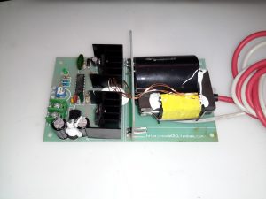
This supply is rated at 1kV-10kV output, at 35W power level. Unfortunately this supply isn’t capable of sustaining the discharge in a large He-Ne tube, the impedance of the supply is far too high. Still, it’s useful for other experiments.
The flyback-type transformer clearly isn’t a surplus device from CRT manufacture, as there are very few pins on the bottom, and none of them connect to the primary side. The primary is separately wound on the open leg of the ferrite core.
Drive Electronics
Drive Electronics

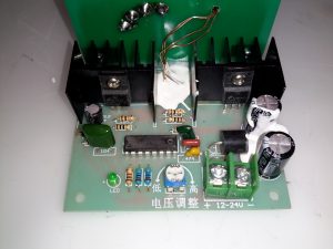
The drive electronics are pretty simple, there’s a controller IC (with the number scrubbed off – guessing it’s either a 556 dual timer or a SMPS controller), a pair of FDP8N50NZ MOSFETs driving the centre-tapped primary winding.
The drive MOSFETs aren’t anything special in this case: they’re rated at 500v 8A, 850mΩ on resistance. This high resistance does make them get rather hot even with no load on the output, so for high power use forced-air cooling from a fan would definitely be required.
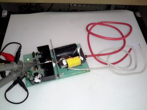
Test Setup
Test Setup

Here’s the supply on test, I’ve got the scope probes connected to the gate resistors of the drive MOSFETs.
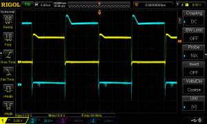
Waveforms
Waveforms

On the scope the primary switching waveforms can be seen. The FETs operate in push-pull mode, there’s a bit of a ring on the waveform, but they’re pretty nice square waves otherwise.
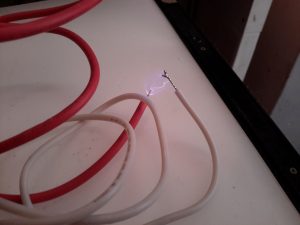
Arc
Arc

At maximum power on 12v input, about 25mm of gap is possible with an arc.
Posted on 4 Comments

Eberspacher Controller & Remote

7-Day Programmer
7-Day Programmer

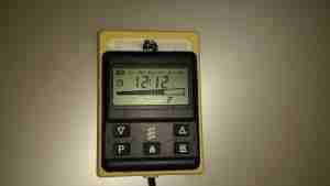
The Eberspacher heaters can be controlled with a single switch, but it’s more convenient to have some temperature control & the option of a timer. Above is an ex-BT 701 series controller, with built in 7-day programmer. Being an ex-BT van version though, it’ll only switch the heater on for 1 hour at a time.
To get around this slight niggle, I fitted a bypass toggle switch.

Remote Control
Remote Control

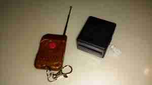
For a bit of extra convenience, I got an RF remote controlled relay module from eBay (£5).
This allows me to switch things on remotely, so I can return to a nice toasty tent while camping.
There is an official RF remote for Eberspacher heaters, but I’ve no doubt they’re hideously expensive.

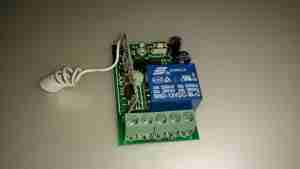
RF Receiver
RF Receiver

Here’s the receiver PCB, there’s an EEPROM & a microcontroller onboard for handling the codes the remotes send, but as the number has been scrubbed off the micro, no data there. This uses a standard RF receiver module.

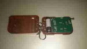
RF Remote
RF Remote

Here’s the remote itself, this uses a 12v battery instead of a 3v lithium cell. A little of a pain since these batteries can be a bit pricey.
As this RF system operates on 315MHz, it’s technically illegal in the UK, but I was unable to find a 433MHz version with the features required. Nevermind ;).

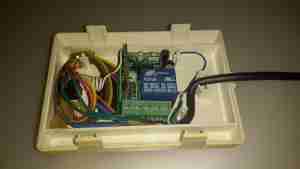
Controller Internals

Here’s the module installed in the controller casing. I have since run the antenna wire around the edge of the case to try & get the furthest range on receive. The relay contacts are just paralleled across the bypass switch, so when the relay energizes the heater fires up.
Luckily the thermostatic control portion of the 701 programmer is operational even when heating mode is not active.

Posted on Leave a comment

Belling Microwave


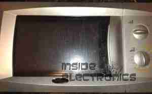
Front
Front

Here is a cheap no frills microwave oven, which died after a few weeks of normal use.

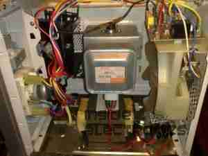
Electronics Bay
Electronics Bay

Cover removed, showing the internals. Front of the microwave is on the left.

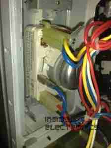
Timer
Timer

Closeup of the timer unit. Cheap & nasty.

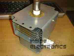
Magnetron
Magnetron

Magnetron removed from the oven. Antenna is on the top,  cooling fins visible in the center. White conector at the bottom is the filament terminals.

Magnetron Chokes
Magnetron Chokes

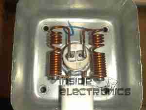
Chokes on the magnetron’s filament connections. These prevent microwave energy from feeding back into the electronics bay through the connections.

Magnetron Assembly
Magnetron Assembly

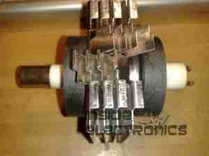
Magnetron cooling fins, tube & magnets removed from the frame.

Magnetron Tube
Magnetron Tube

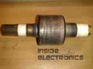
Bare magnetron tube.

Power Input Board
Power Input Board

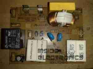
This PCB does some rudimentary power conditioning, power resistors are in series with the live feed to the power trasformer, to prevent huge power up surge. When the transformer energizes the relay, which is in parallel with the resistors, switches them out a fraction of a second after, providing full power to the transformer.
Standard RFI choke & capacitor at the top of the board, with the input resistor.

Transformer
Transformer

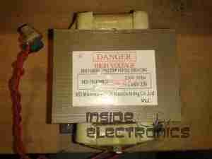
Power transformer to supply the magnetron with high voltage.
Power output is ~2kV at ~0.5A. Pair of spade terminals are the low voltage filament winding.

Capacitor
Capacitor

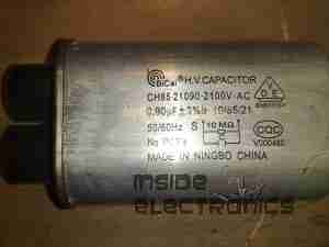
HV Capacitor. This along with the diode form a voltage doubler, to provide the magnetron with ~4kV DC.

Diode
Diode

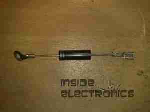
HV diode stack.

Fuse Element
Fuse Element

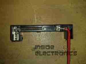
Internals of the HV fuse. Rated for ~0.75A at 5kV. The fuse element is barely visible attached to the end of the spring. Connects between the transformer & the capacitor.

Cooling Fan
Cooling Fan

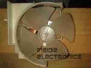
Cooling fan for the magnetron. Drive is cheap shaded pole motor.

Fan Motor
Fan Motor

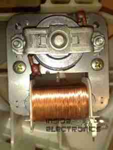
Fan motor. Basic 240v shaded pole induction type.