Posted on Leave a comment

Mini Teardown: Eberspacher 701 BT Controller

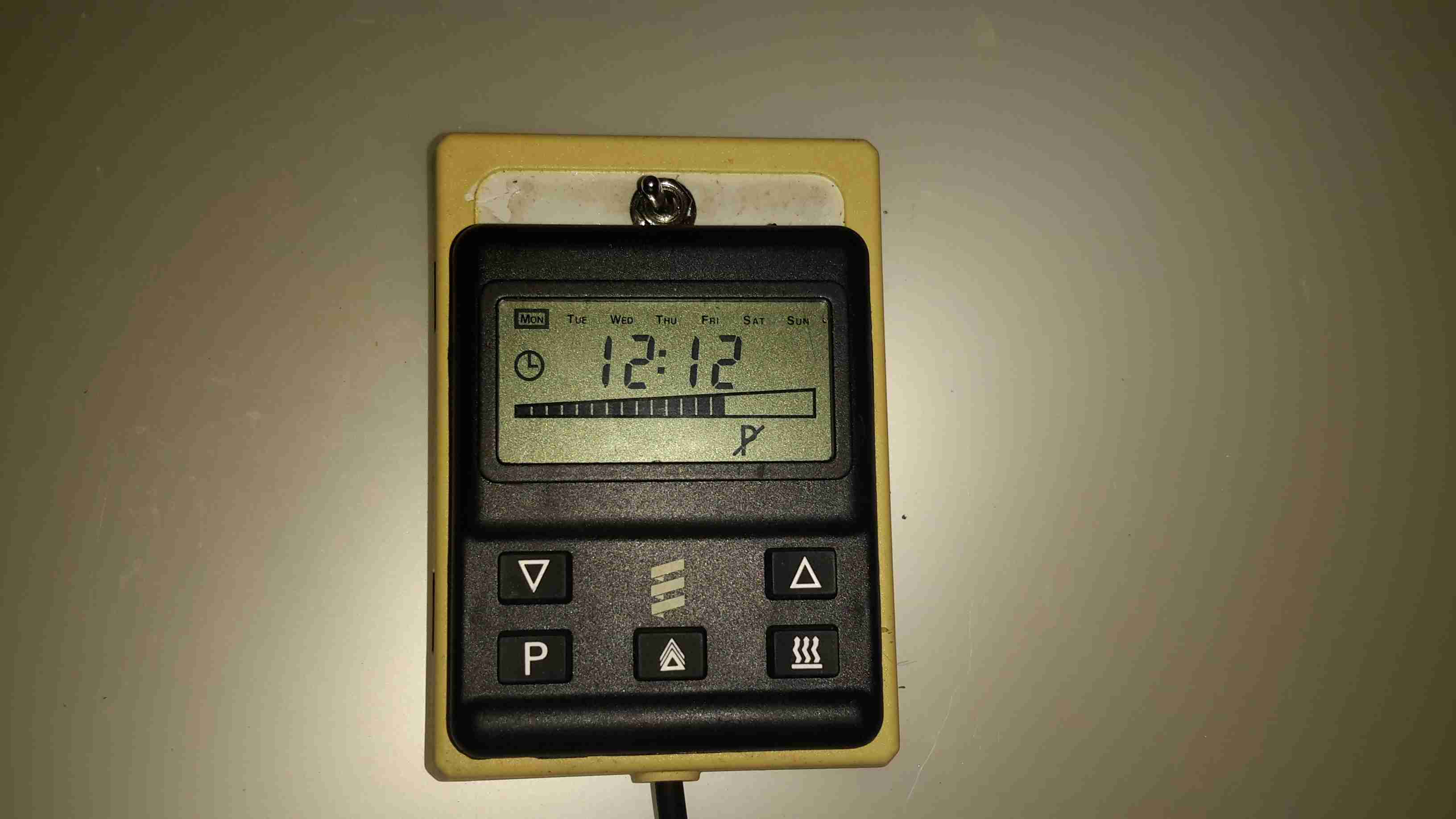
It’s well known that there are two versions of the 701 type controller available for Eberspacher heaters, the version with the blue logo is the official un-restricted model, while the version with the white logo is a version built for BT that restricts the heater to 1 hour runtime & has no diagnostics built in.
As these devices are microcontroller driven, I assumed that the hardware would be the same, only the code running in the micro being the bit that Eberspacher changed. This option would certainly have been the lowest cost.

Controller PCB Rear
Controller PCB Rear

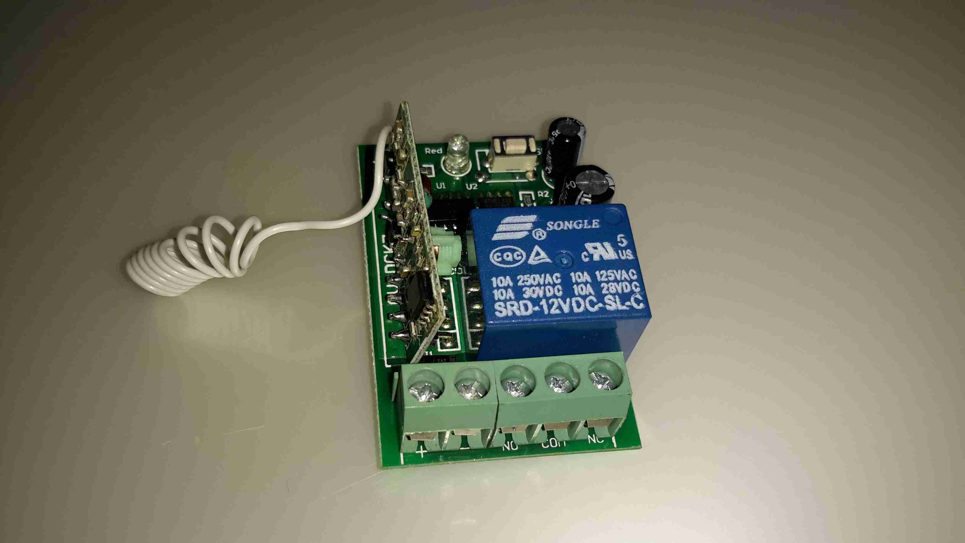
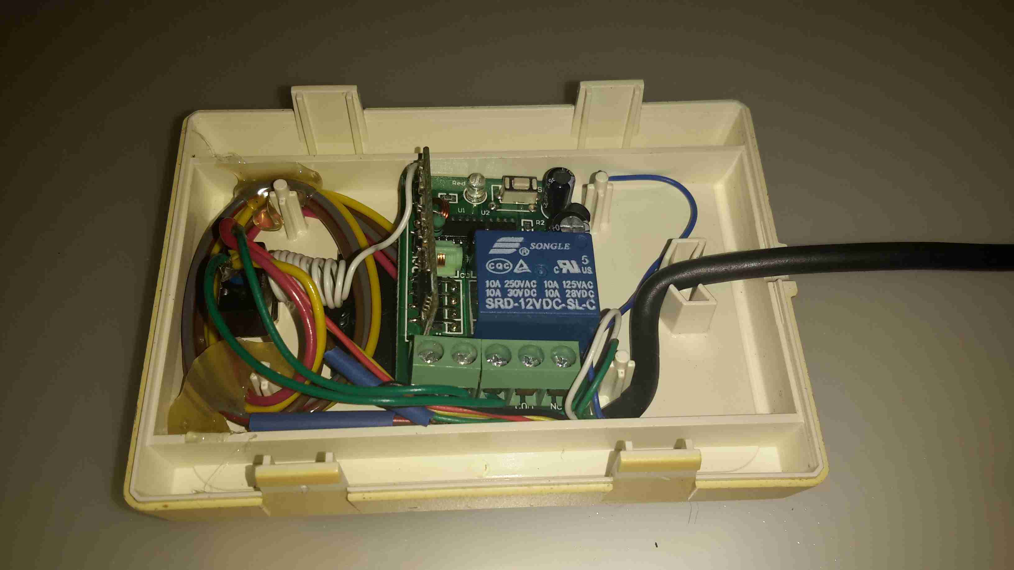
Here’s the PCB removed from the plastic housing. There are definitely some differences that I can tell. As the un-restricted version has an extra wire for the diagnostic serial interface, and this board has no unpopulated parts, the PCB is definitely a different version.
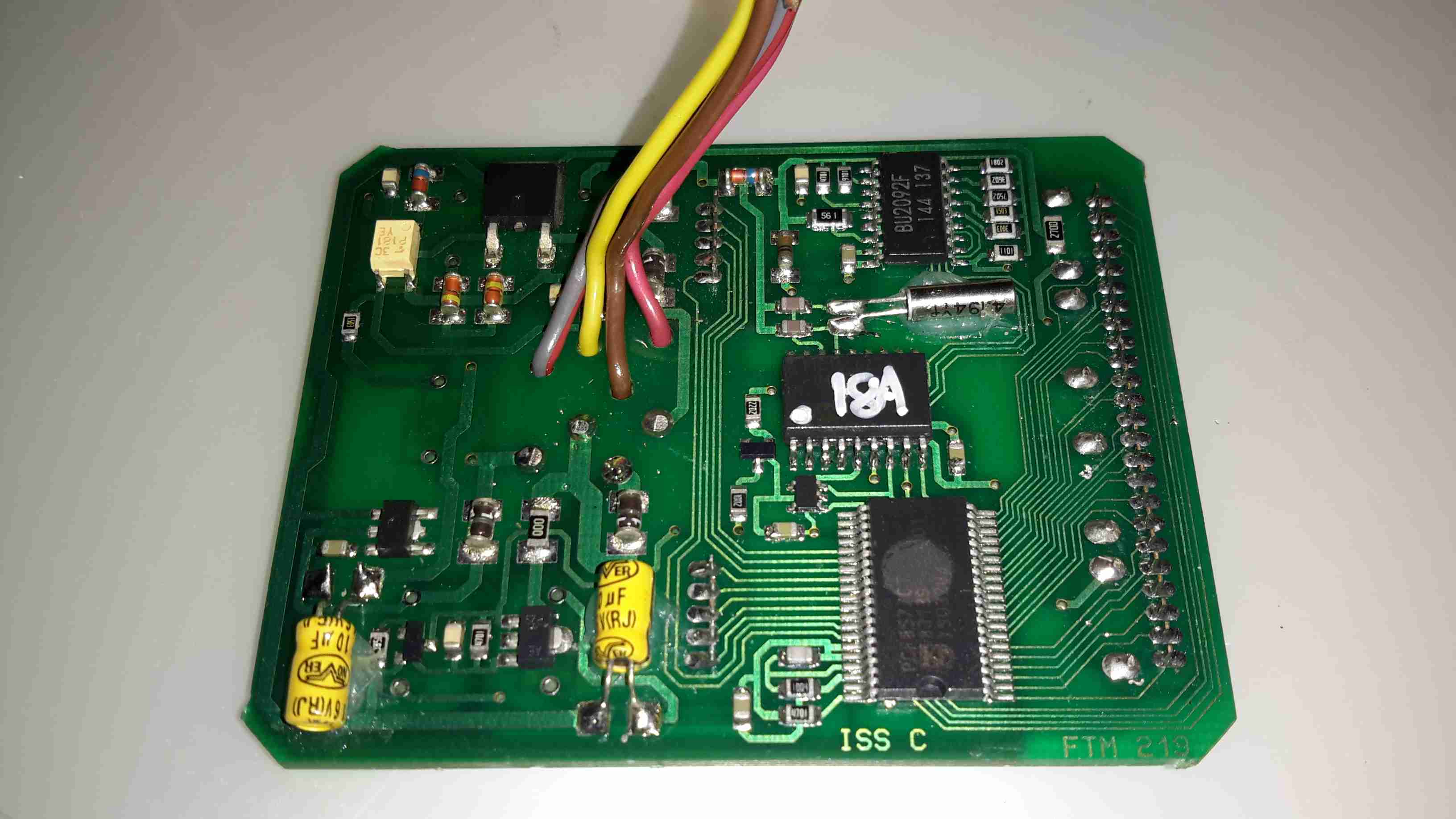
In the centre is a Microchip PIC16C622 microcontroller, the OTP version in this case for cost reductions. (I may try reading the binary from this chip in the future, chances are it’s code protected though).
Below the micro is an NXP PCF8577C 32-segment LCD controller, this has an I²C interface to the PIC.
The temperature control function on these heaters is done via applying a resistance to one of the control lines, between 1750Ω-2180Ω, ±80Ω. (Very odd values these, not to mention no standard components can create this range easily, bloody engineers >_<). This is accomplished in hardware with a BU2092F I²C shift register from Rohm, which is connected to a bank of resistors. The microcontroller will switch combinations of these into the circuit to get the range of resistances required.
The rest of the circuit is local power regulation & filtering.

Controller PCB Front

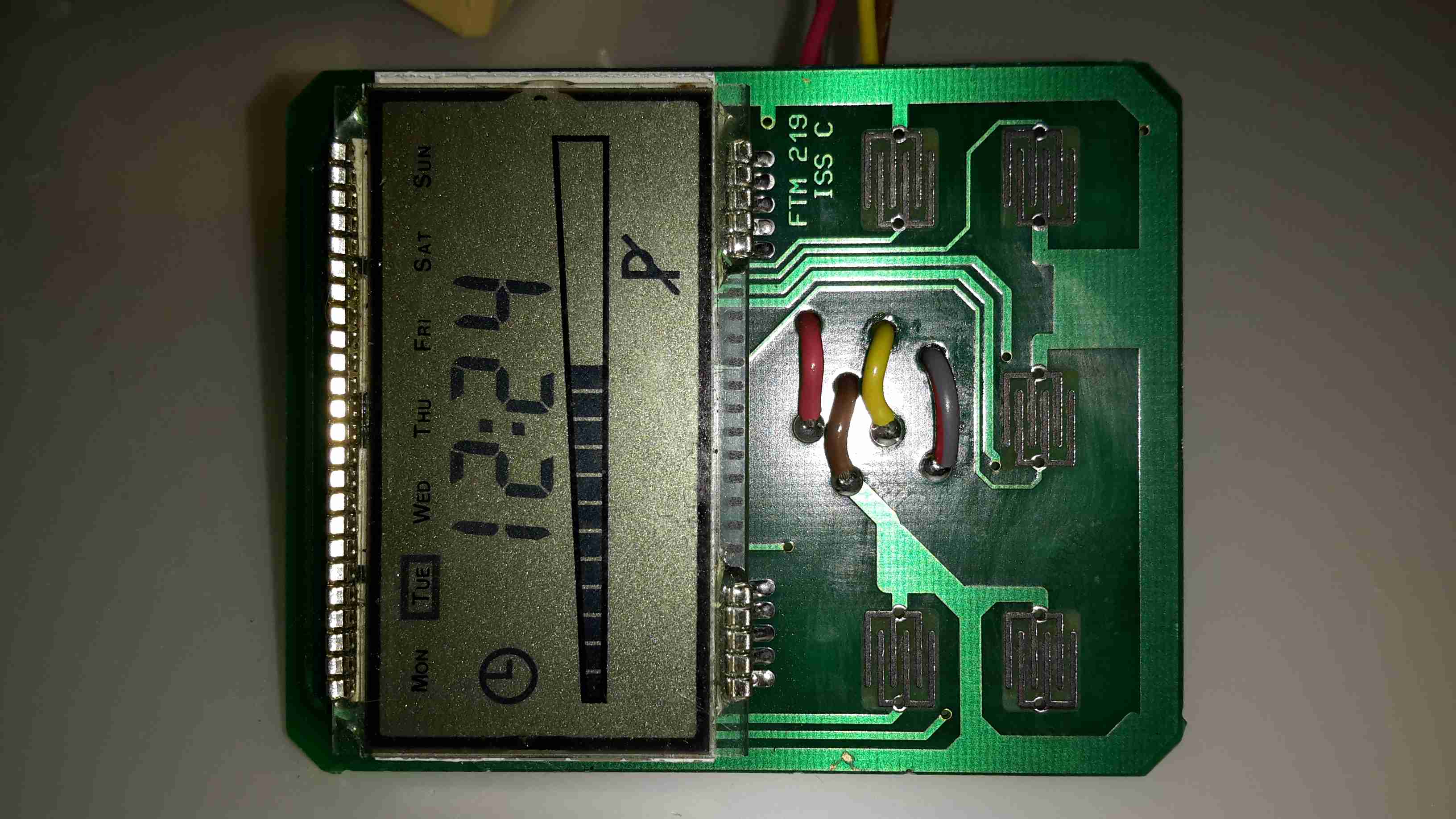
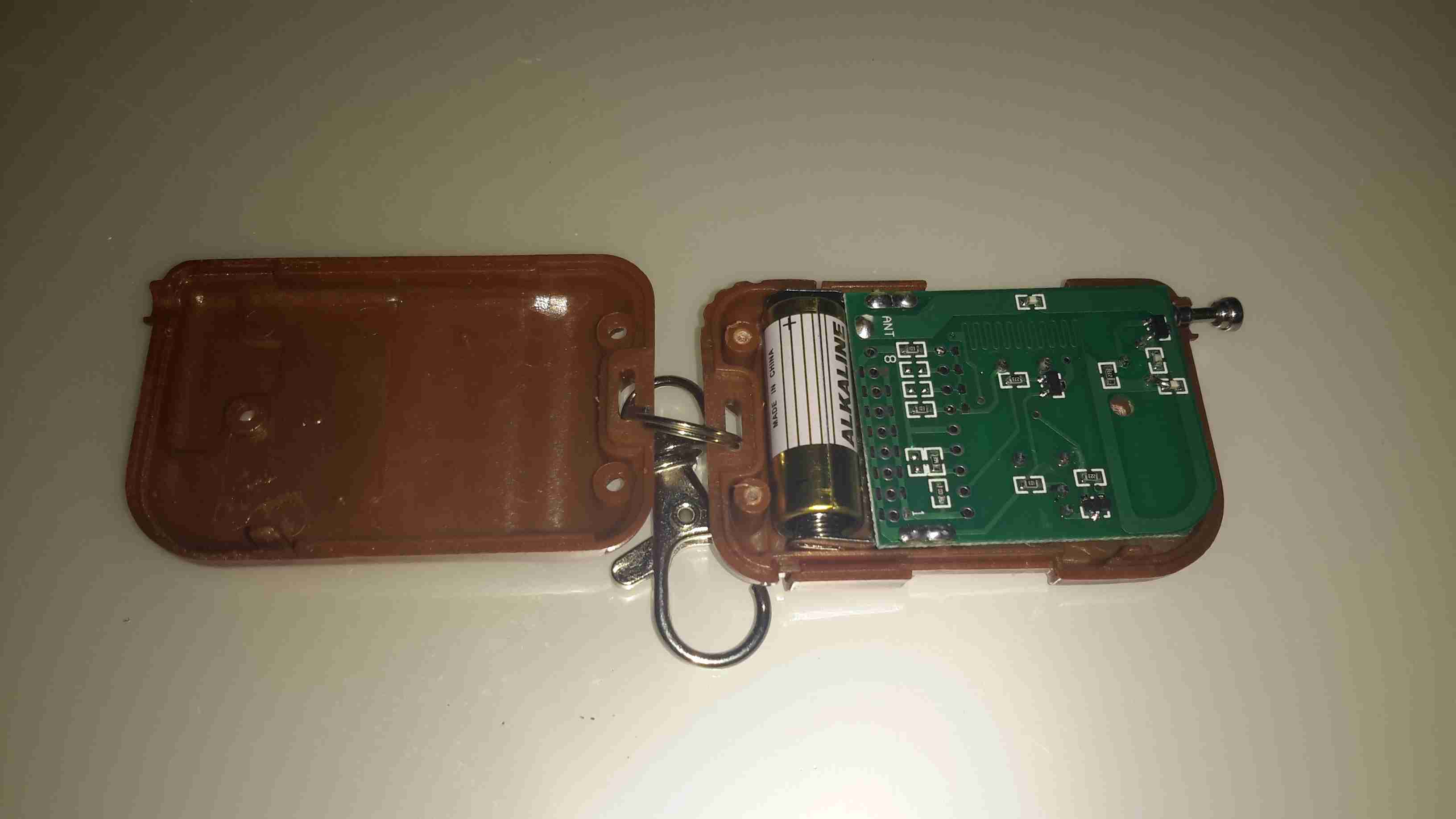
There’s not much on the other side of the PCB, just the LCD itself & the contacts for the buttons.

Posted on 4 Comments

Eberspacher Controller & Remote

7-Day Programmer
7-Day Programmer

The Eberspacher heaters can be controlled with a single switch, but it’s more convenient to have some temperature control & the option of a timer. Above is an ex-BT 701 series controller, with built in 7-day programmer. Being an ex-BT van version though, it’ll only switch the heater on for 1 hour at a time.
To get around this slight niggle, I fitted a bypass toggle switch.

Remote Control
Remote Control

For a bit of extra convenience, I got an RF remote controlled relay module from eBay (£5).
This allows me to switch things on remotely, so I can return to a nice toasty tent while camping.
There is an official RF remote for Eberspacher heaters, but I’ve no doubt they’re hideously expensive.

RF Receiver
RF Receiver

Here’s the receiver PCB, there’s an EEPROM & a microcontroller onboard for handling the codes the remotes send, but as the number has been scrubbed off the micro, no data there. This uses a standard RF receiver module.

RF Remote
RF Remote

Here’s the remote itself, this uses a 12v battery instead of a 3v lithium cell. A little of a pain since these batteries can be a bit pricey.
As this RF system operates on 315MHz, it’s technically illegal in the UK, but I was unable to find a 433MHz version with the features required. Nevermind ;).

Controller Internals

Here’s the module installed in the controller casing. I have since run the antenna wire around the edge of the case to try & get the furthest range on receive. The relay contacts are just paralleled across the bypass switch, so when the relay energizes the heater fires up.
Luckily the thermostatic control portion of the 701 programmer is operational even when heating mode is not active.

Posted on 1 Comment

12v Temperature Controlled Soldering Iron

In my shack, 99% of my gear is all 12v powered, which is good for a few reasons:

  • Single Power Supply – This increases efficiency, as I’m only getting the losses of a single supply.
  • Safety – Mains voltages are dangerous, I’m not fond of working on such equipment.
  • Portability – I can power everything pretty much no matter were I am from a convenient car battery.
  • Convenience – Since everything is single supply, with all the same plugs, I don’t have to think about what goes where. This is more important due to my forgetfulness ;).

The one piece of equipment I regularly use that isn’t 12v is my soldering station. This is a Maplin A55KJ digital unit, which uses a 24v heating element.
While the soldering wand works OK when hooked direct to a 12v power supply (only at half power though), this removes the convenience of having temperature control.

The circuitry inside the unit is PIC microcontroller based, and doesn’t even bother rectifying the AC from the supply transformer before it’s sent to the heater. Because of this there are several reasons why I can’t just hook a DC-DC converter up to it to give it 24v.

It’s sensing the zero-crossing for the triac switch, to reduce heat dissipation, so it refuses to work at all with DC.

On looking at the Great Google, I found a project on Dangerous Prototypes, an Arduino based PID controller for soldering irons.

This requires that the soldering wand itself contains a thermocouple sensor – as the Maplin one I have is a cheap copy of the Atten 938D, it doesn’t actually use a thermocouple for temperature sensing. It appears to read the resistance of the element itself – Nichrome heating elements change resistance significantly depending on temperature.

I’ve managed to find a source of cheap irons on eBay, with built in thermocouples, so I’ve got a couple on order to do some testing with. While I wait for those to arrive, I’ve prototyped up the circuit on breadboard for testing:

Prototype
Prototype

I’ve remapped some of the Arduino pins, to make PCB layout less of a headache, but the system is working OK so far, with manual input for the sensed temperature.
I’m using an IRL520N logic-level HEXFET for the power switching, rated at 10A. As the irons only draw a max of 4.5A, this is plenty beefy enough.
To come up with the +24v supply for the heater, a small DC-DC converter will be used.

More to come when the components for the thermocouple amplifier arrive, and the soldering irons themselves!