Since the entire country is on Coronavirus lockdown at the moment, I figured it was time to get round to finishing off a couple of small blog posts while waiting for the restrictions to be lifted 😉
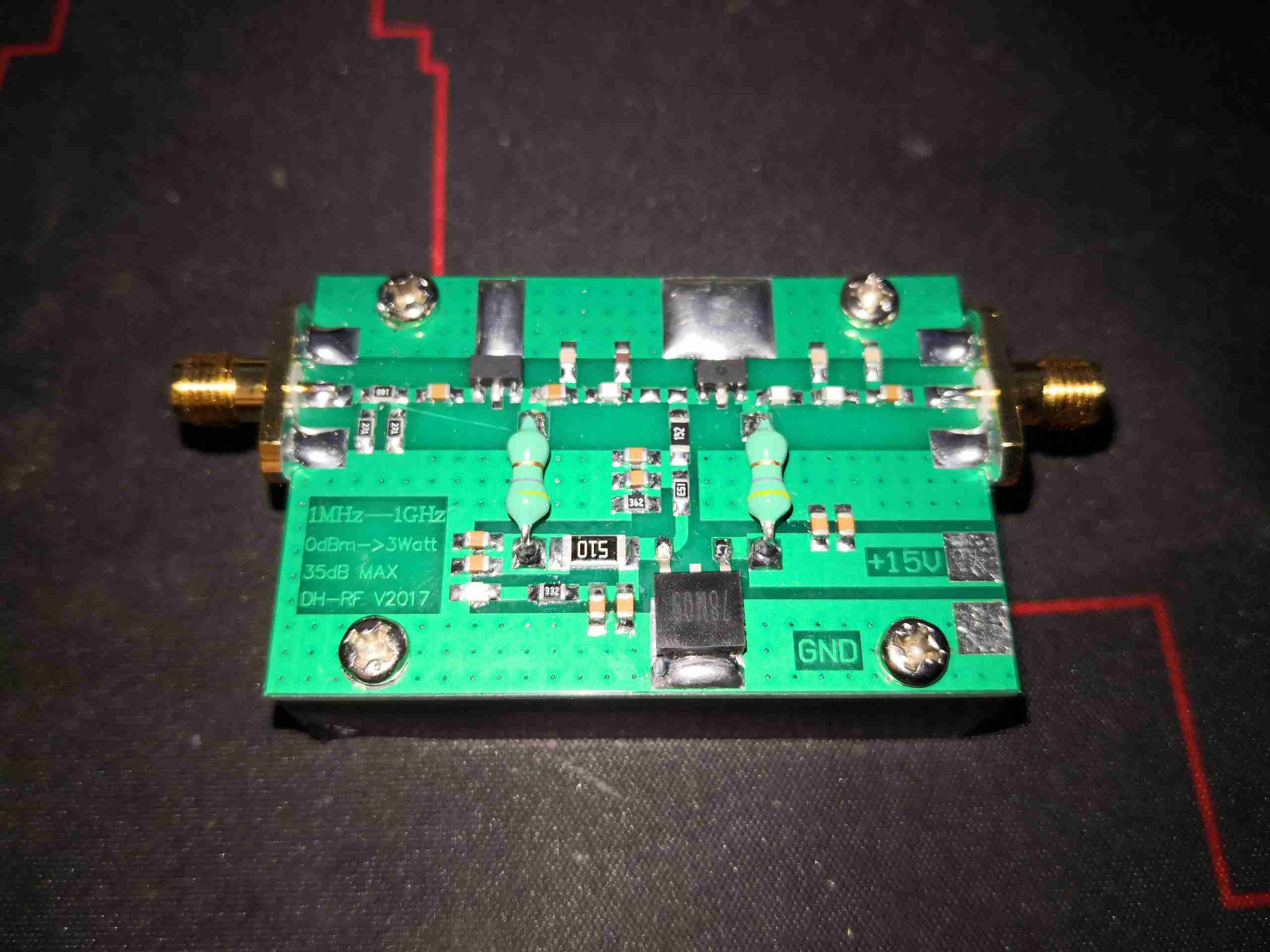
3W 1GHz Amplifier
This is a small two-stage linear amplifier module available on eBay fairly cheap for SDR operation.This unit claims 3W (34.8dBm) power output at 0dBm input, however not surprisingly, this amplifier isn’t quite flat across the frequency range.
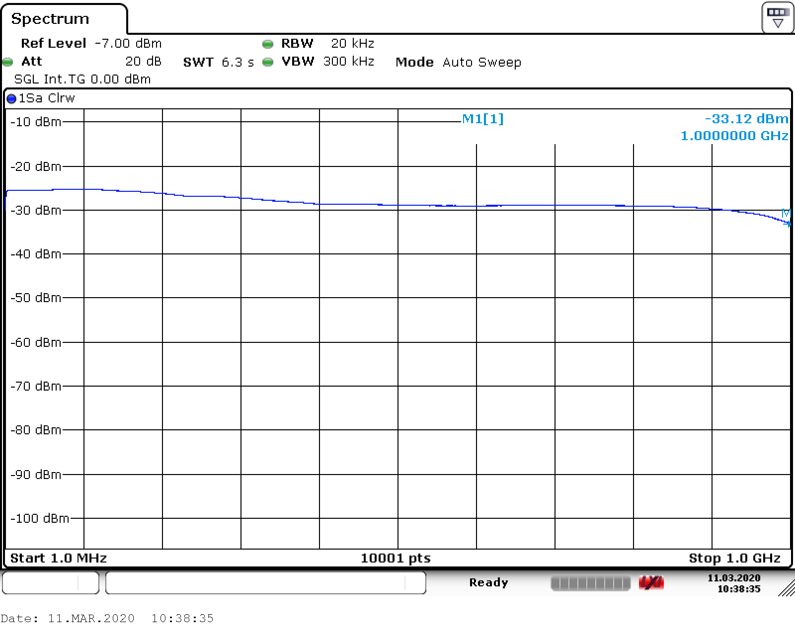
Frequency Response
Here’s the readout from an R&S FSV7 spectrum analyser. The amplifier is being driven from the analyser’s tracking generator at 0dBm, and the output is fed back into the input via 60dB of external power attenuation. The span here is 1MHz-1GHz, and at the top end the frequency response is already beginning to drop off a cliff – the 1GHz rating appears to be the 3dB down point. The rated output power of 3W appears to only be attainable below 100MHz for the rated 0dBm input, after that it drops pretty quickly to about -3dB.
Frequency
Output - dBm
Output - W
100MHz
34.74
2.97
144MHz
34.4
2.75
200MHz
33.81
2.40
315MHz
32.59
1.81
433MHz
31.46
1.39
500MHz
30.91
1.23
600MHz
30.87
1.22
700MHz
31.04
1.27
800MHz
30.95
1.24
900MHz
30.24
1.05
1000MHz
26.86
0.48
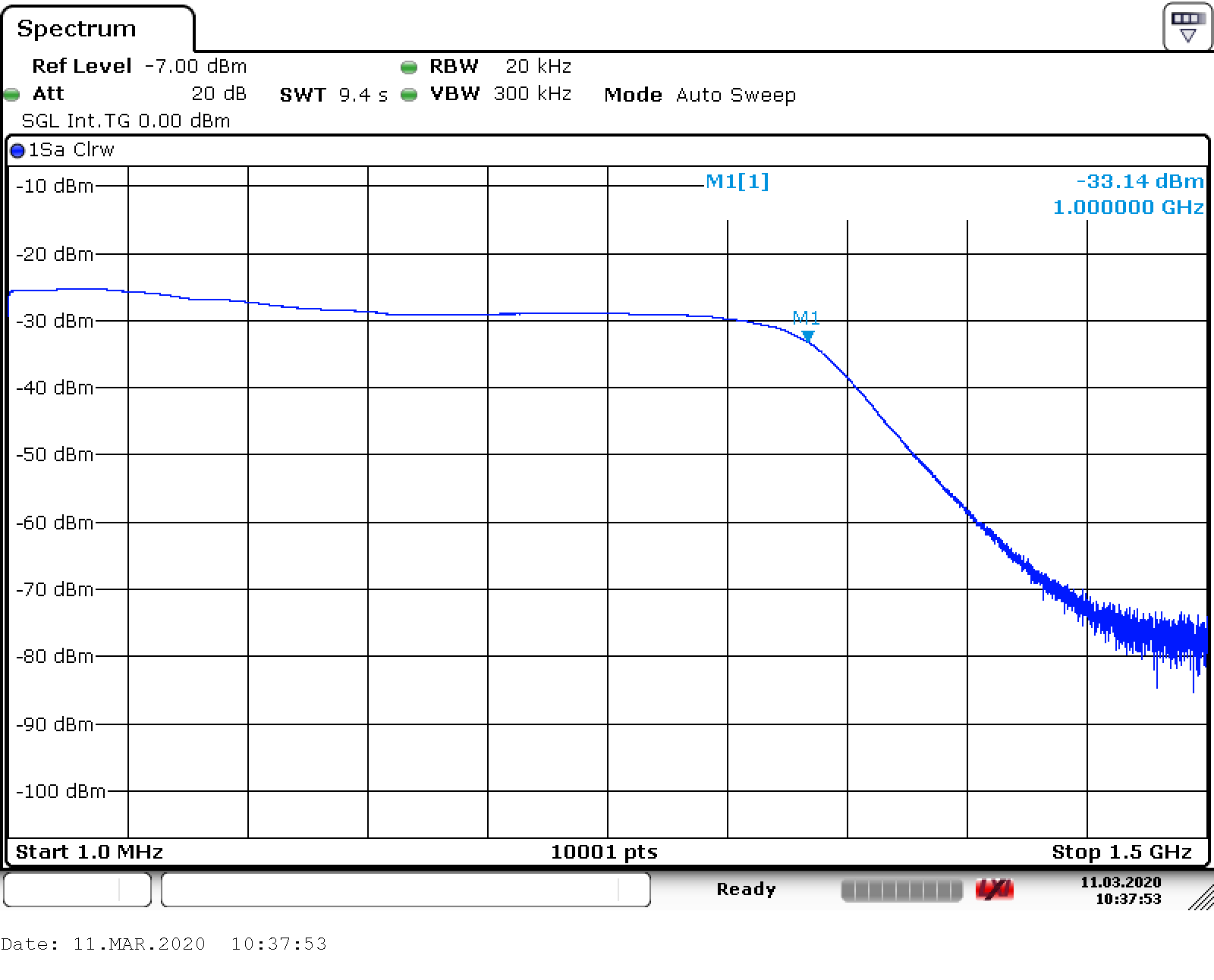
Extended Span
Extending the frequency span of the analyser shows the roll off at high frequency – this module really isn’t usable above the rated frequency range.
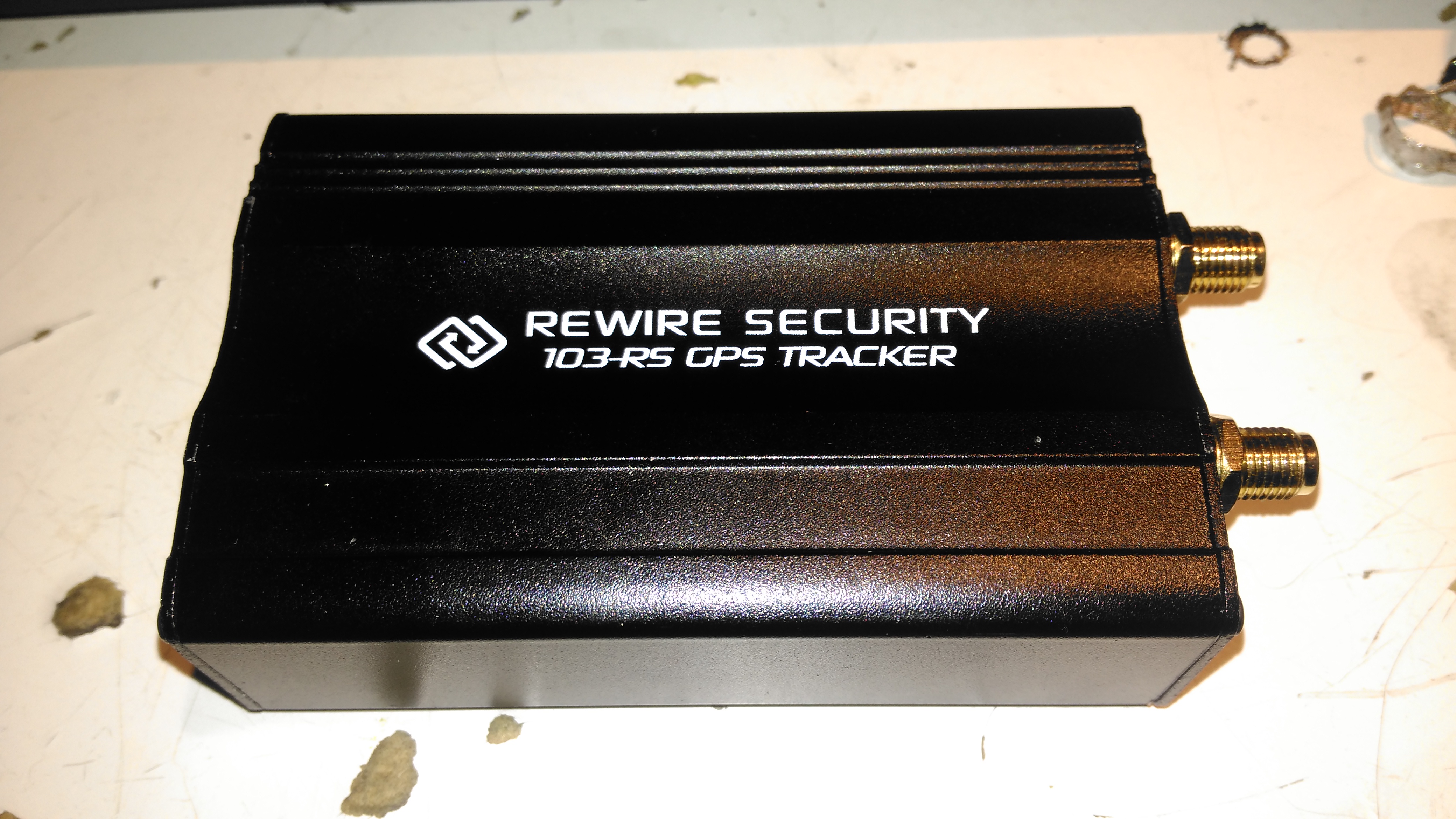
I thought it was time to add a bit of security to the gear I take camping, so this GPS tracker unit was sourced from eBay. This is a Rewire Security 103RS, a slightly customised version of the common Chinese TK103 GPS tracker.
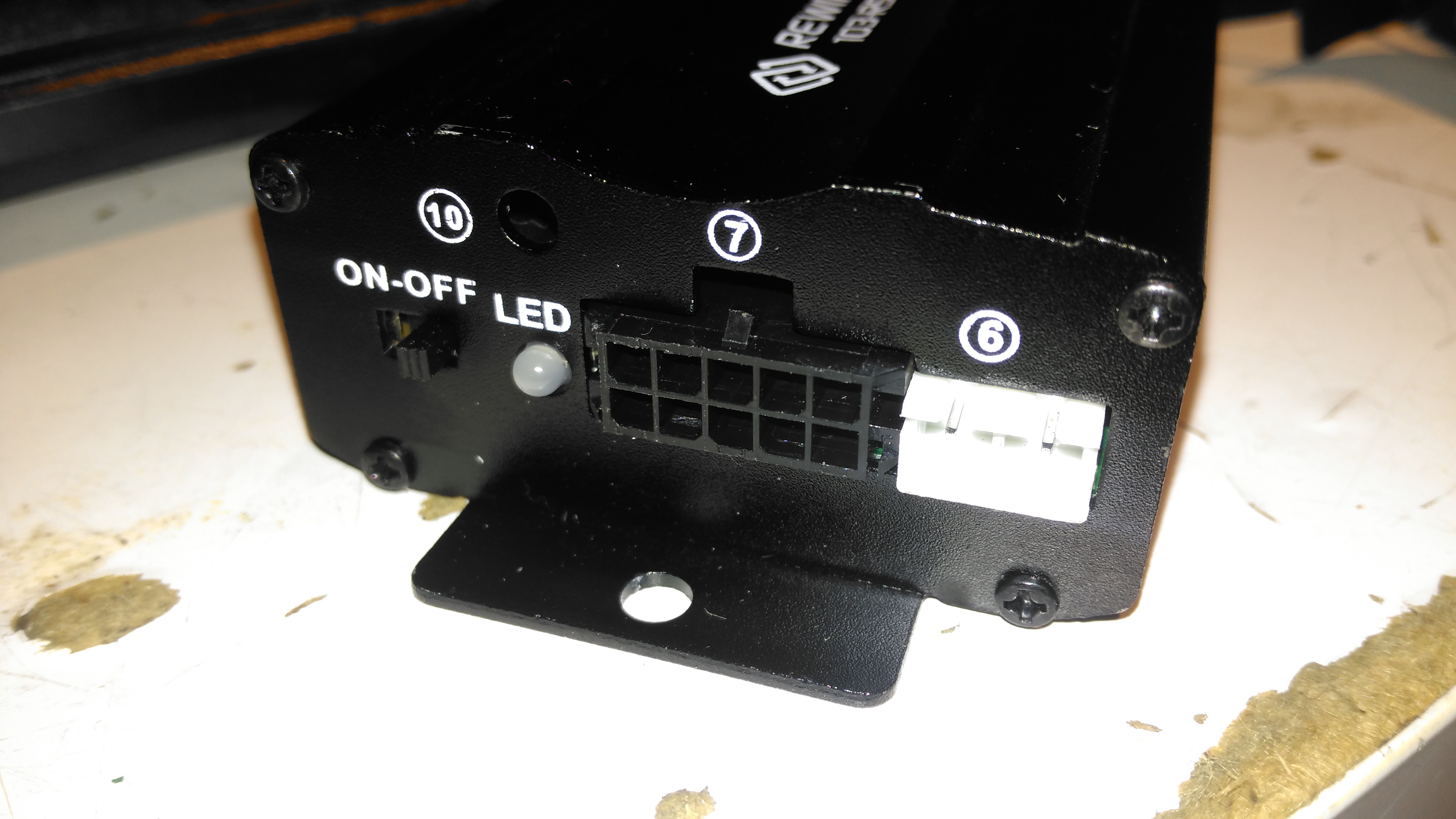
Input Connections
The small module has all it’s power connections on one end of the unit, on a Molex multi-way block. The white connector is for a piezo-shock sensor – this interfaces with the alarm functionality of the unit. There’s an indicator LED for both the GPS & GSM status, and a switch for the backup battery.
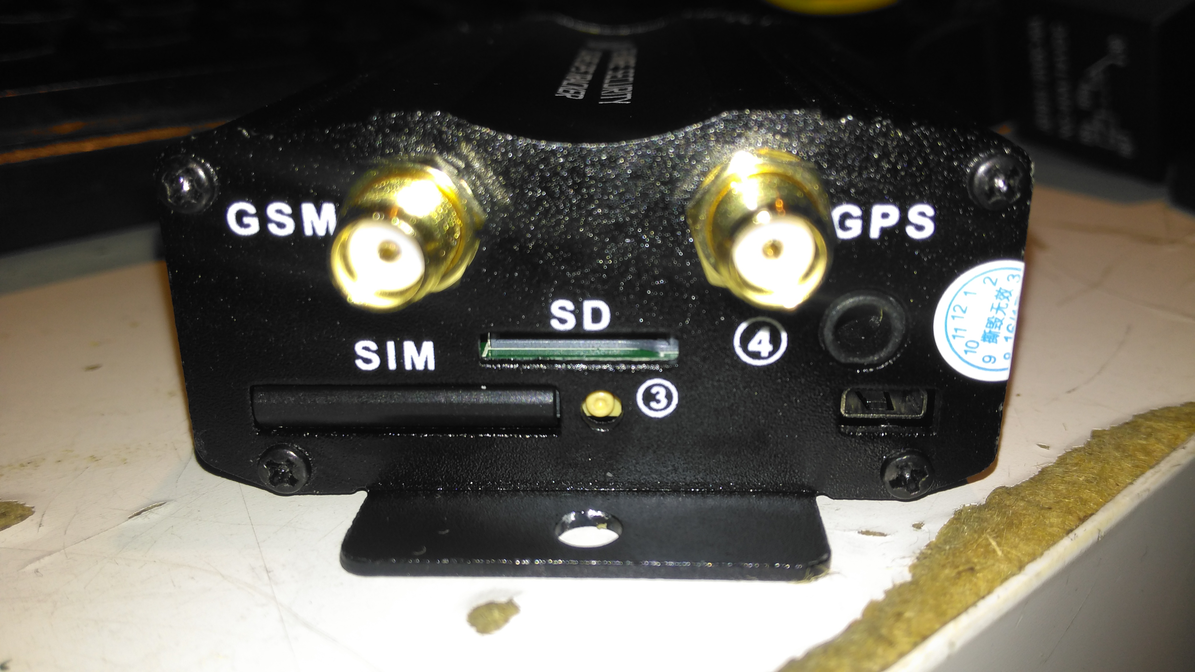
Antenna Connections
The other end has the antenna connections, microphone connection for the monitor function, along with the SIM & SD card slots.
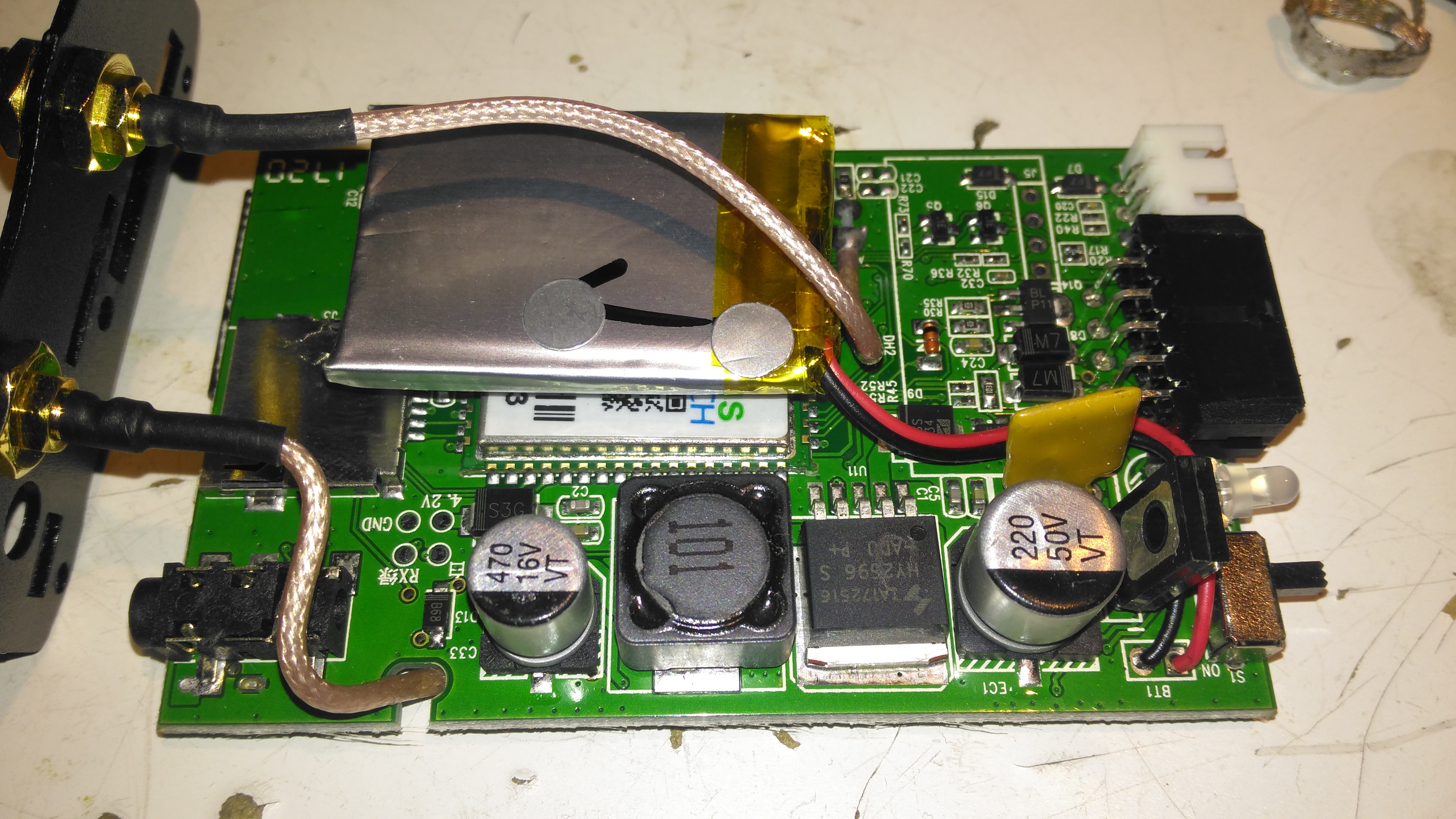
PCB Top
Once the end panel is removed, the PCB just slides out of the aluminium extruded casing. It’s pretty heavily packed with components in here. A switching regulator deals with the 12v input from the vehicle battery, and is protected by a polyfuse on the right. The GSM module is hiding under the Li-Po backup cell, unfortunately the sticky pad used to secure this wouldn’t come off without damaging something. The pigtails for both the GPS & GSM antennas are permanently soldered to the board here.
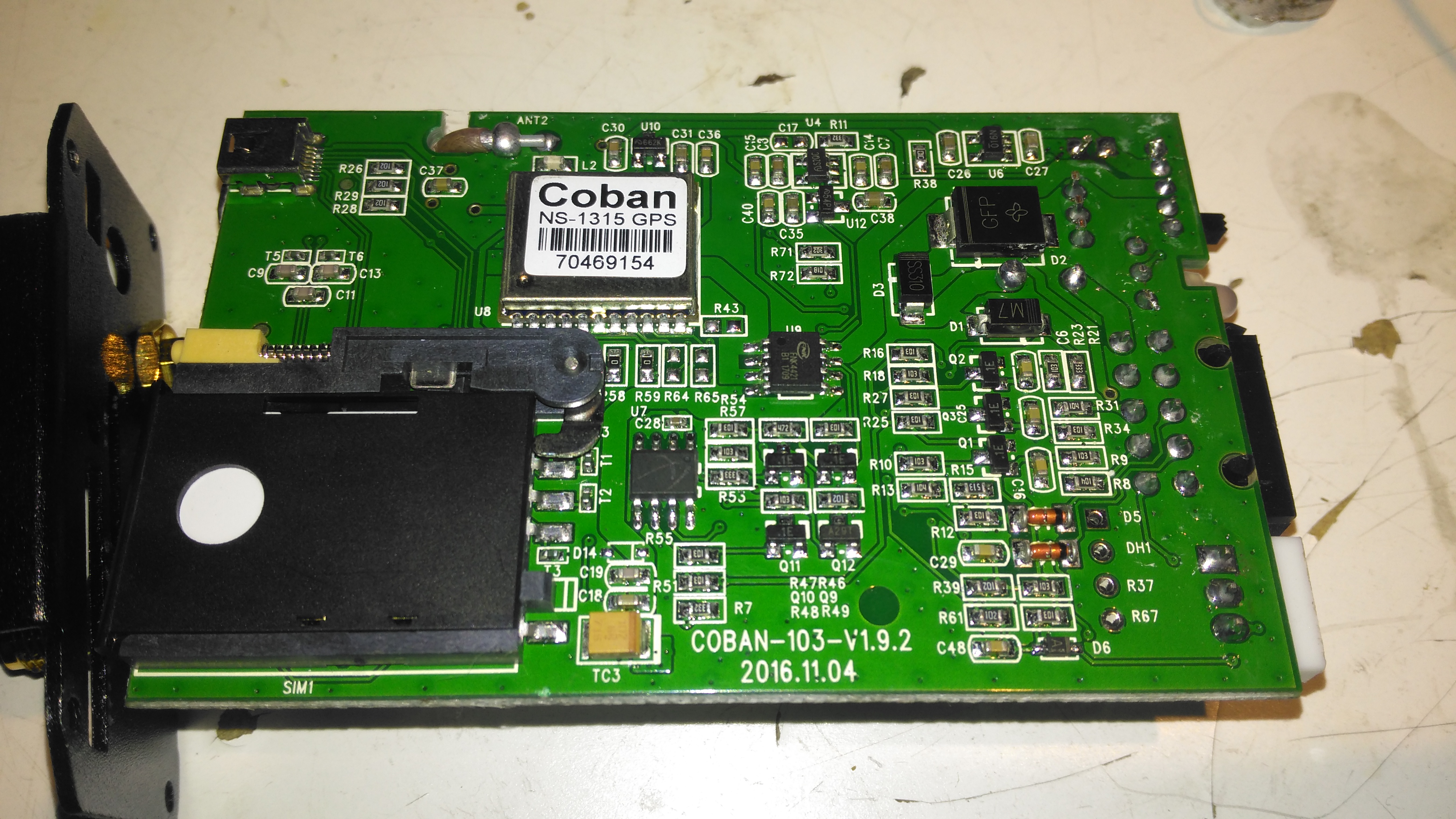
PCB Bottom
The bottom of the PCB has the GPS module, and mainly input protection & bypassing components. There is a FNK4421 Dual P-Channel MOSFET here as well, probably used for switching the external relay or alarm siren. The SIM socket for the GSM modem is located here in the corner.
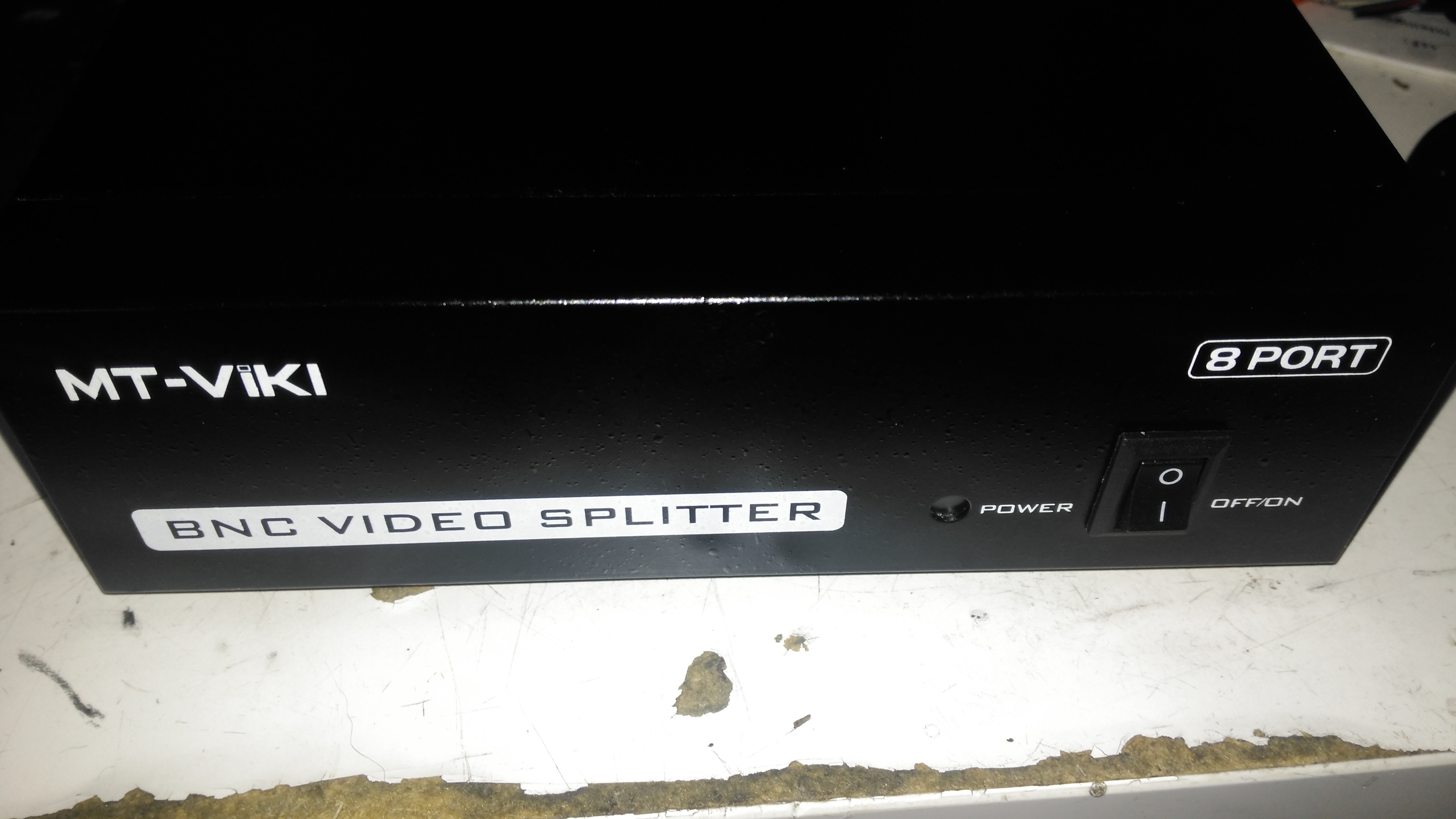
Time for another eBay special: this time it’s an 8-port video distribution amplifier, with BNC connections designed for commercial/industrial equipment. Not much on the front panel above, apart from the power switch & LED.
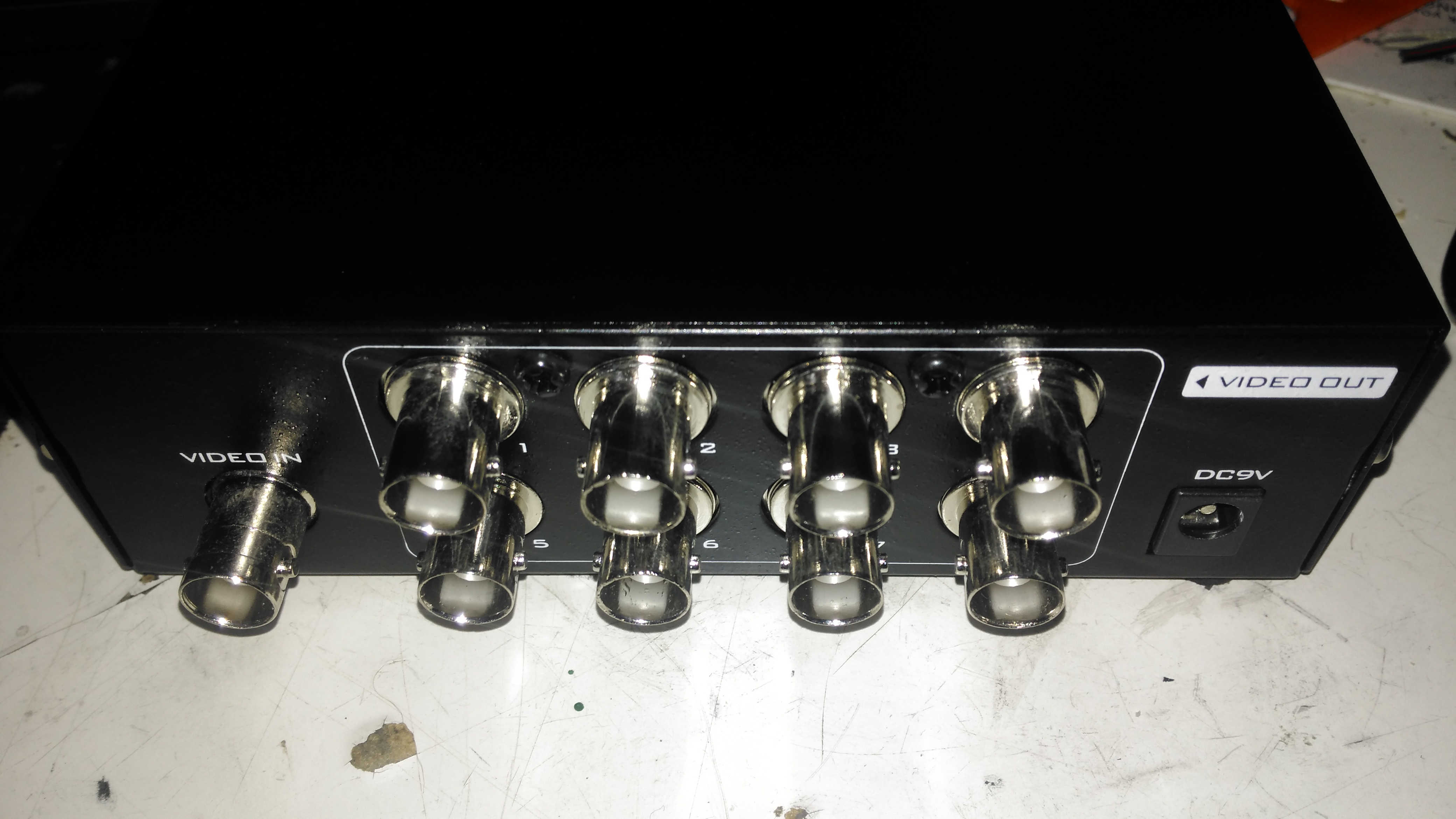
Rear Panel
The rear panel has all the connectors, input is on the left, while the outputs are in the centre. Power is supplied through the barrel jack on the right, 9v DC in this case.
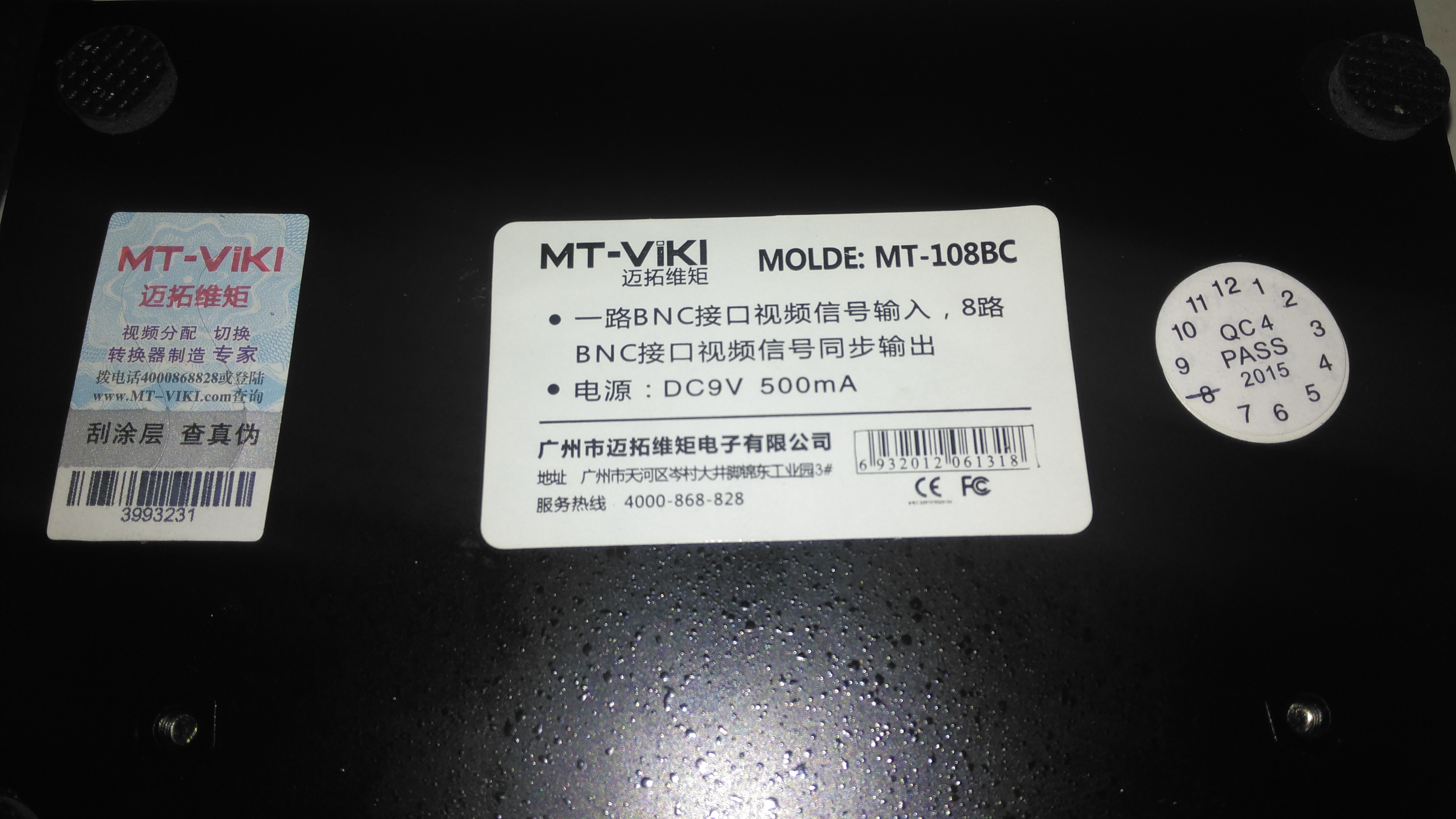
Data Label
Not much in English on the data labels, there’s also an authenticity label on the left to make sure you don’t get a fake.
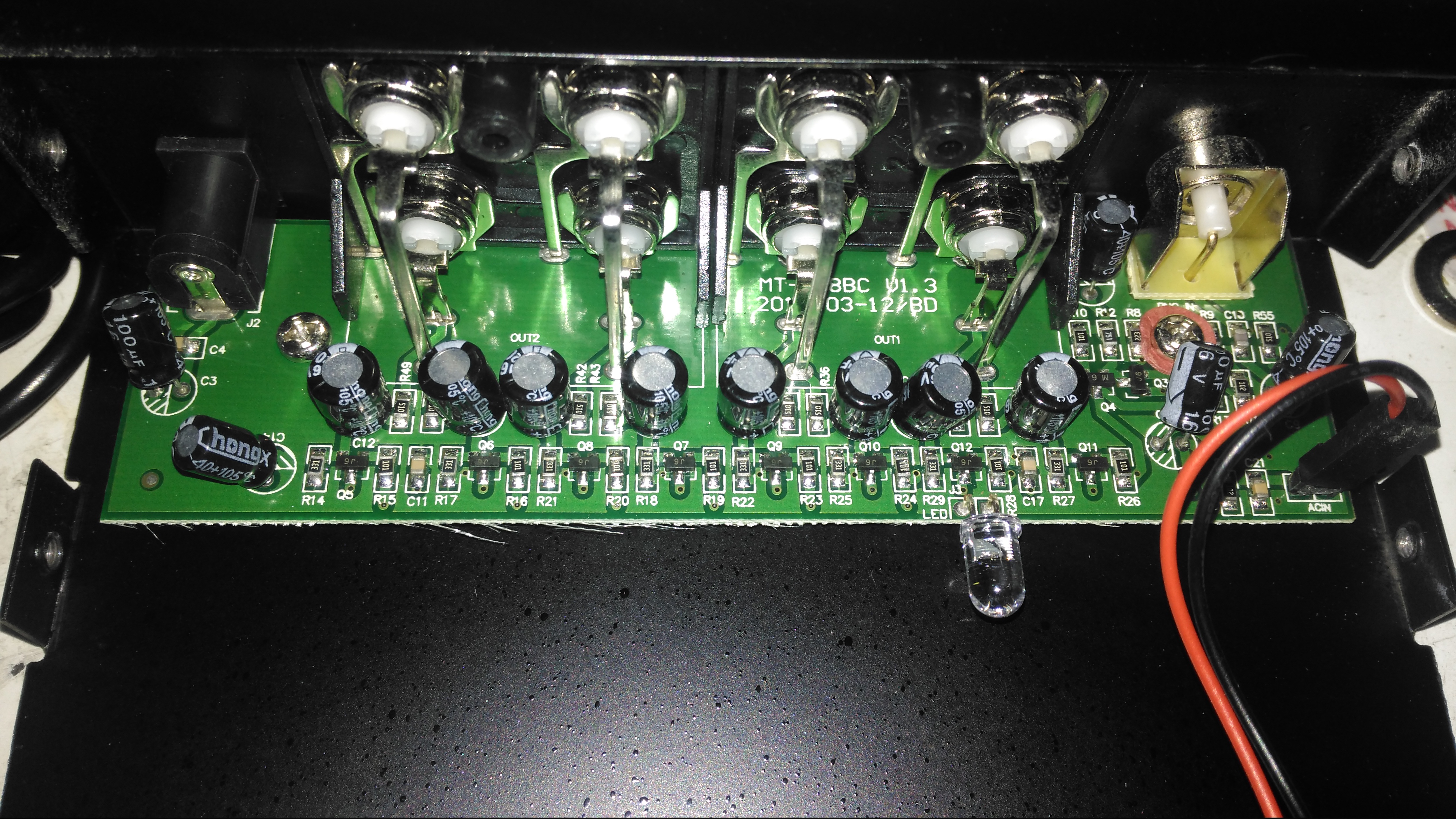
Amplifier Board
Taking the lid off reveals a very small PCB, taking up less than a third of the aluminium case! The input stage is on the right, composed of a pair of SOT-23 transistors to buffer the incoming signal. There’s an KST812M6 PNP & an S9014 NPN Epitaxial. The signal is then fed to the output stages, all individual S9014 NPN transistors to the output ports.
The power LED is just poking in the general direction of the hole in the front panel, so this isn’t likely to work very well – it’s going to illuminate the inside of the case more!
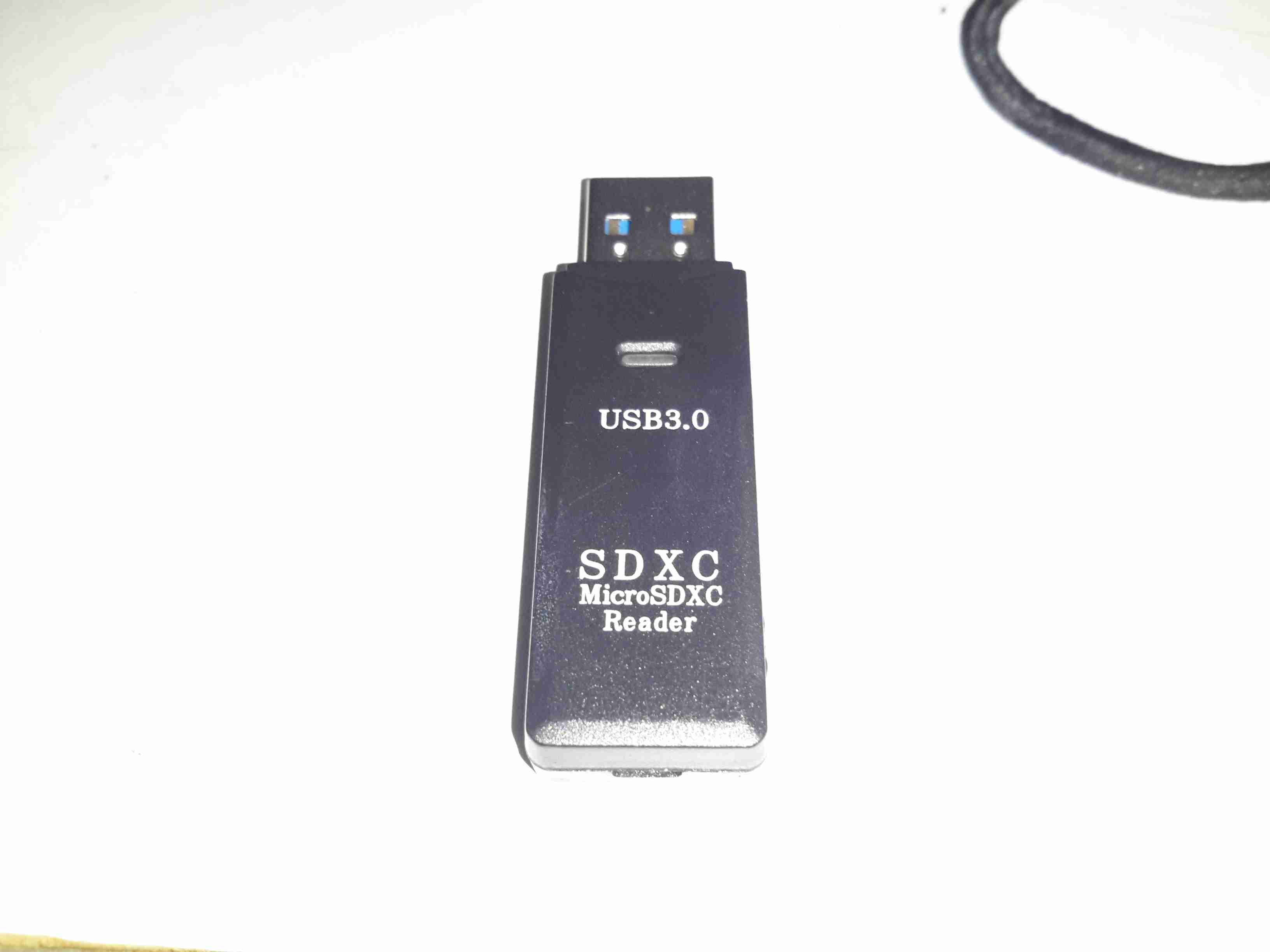
This is a cheap little eBay reader to replace my ~10 year old multi-reader that very recently died. My original was an 8-in-1 version, but as I never read anything else other than SD cards these days, a little USB dongle version was more convenient.
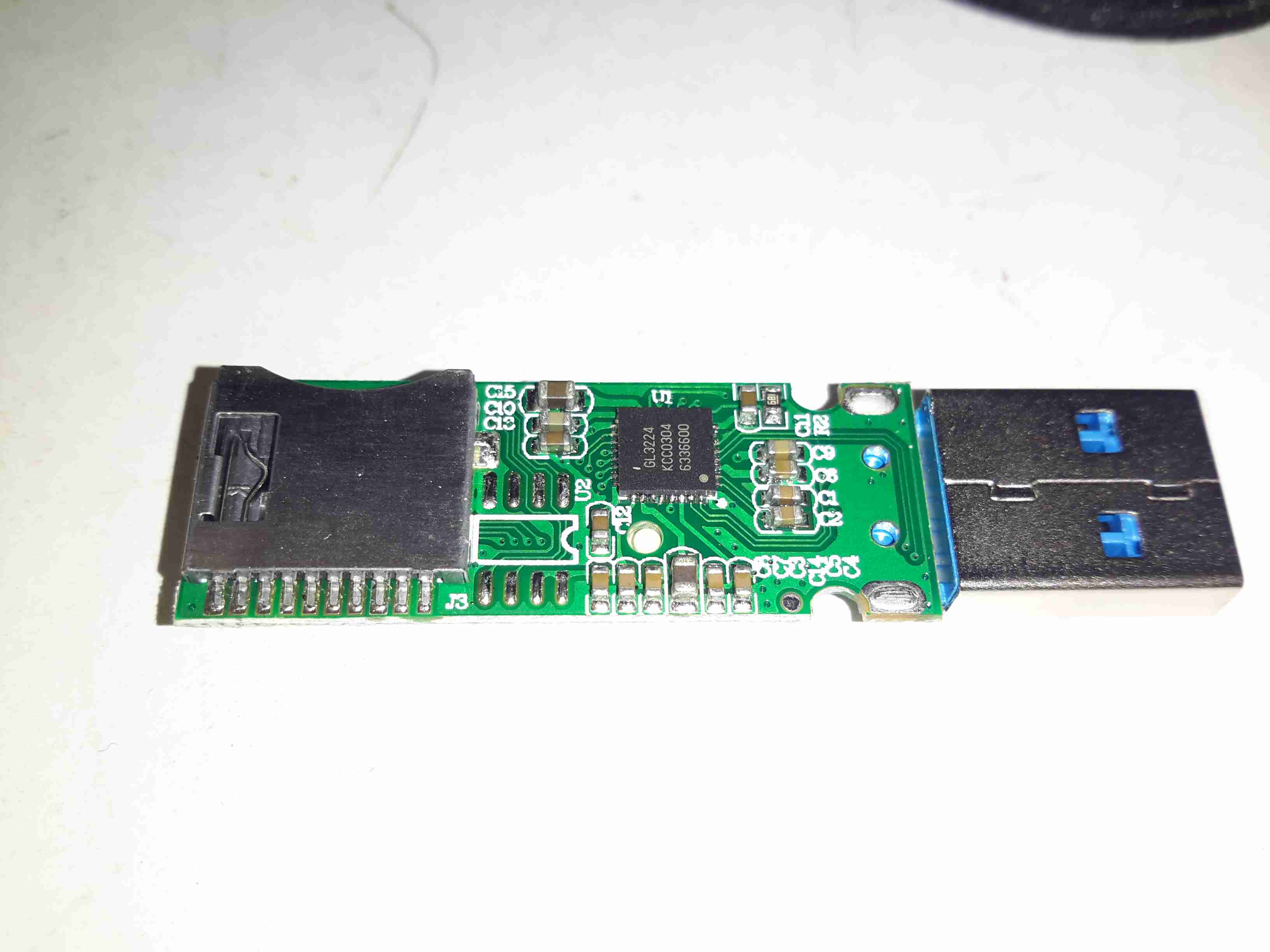
Controller Chipset
The layout is very minimal, just the µSD socket, bypass passives & the main controller chip on this side, which is a GL3224 Dual LUN Memory Card Controller from Genesys Logic. This is fully USB3 capable according to the datasheet, but I’m not certain of the advantage of this for something that reads relatively slow devices like SD cards.
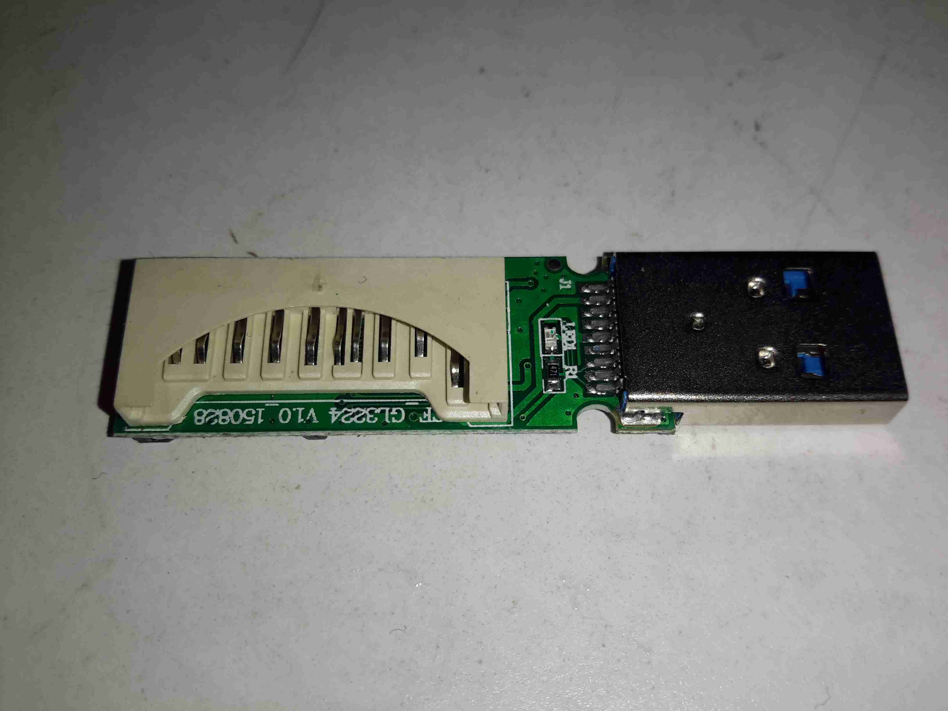
SD Socket
The other side of the PCB holds the full size SD socket, along with the activity LED & USB connector.
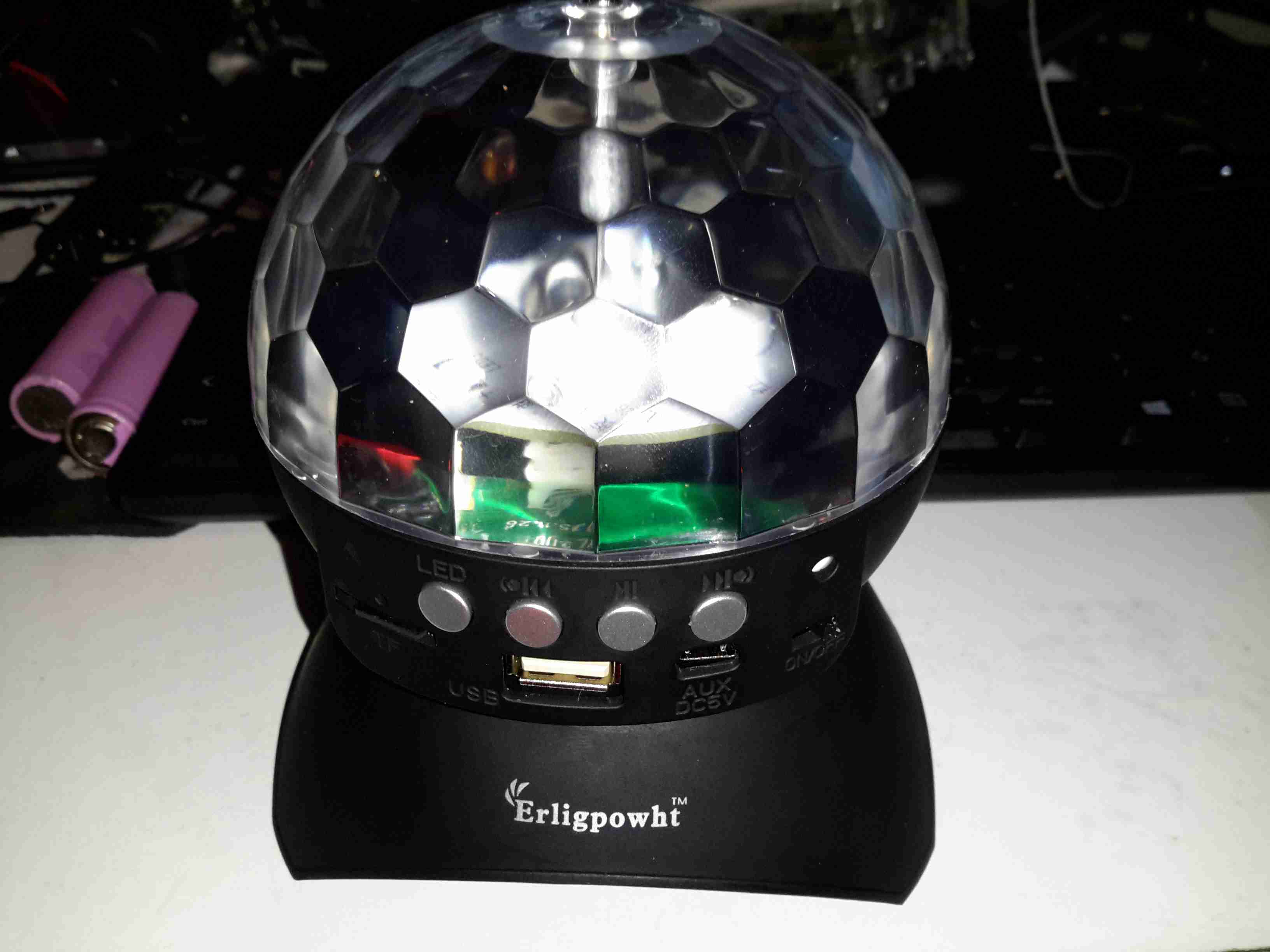
Here’s an eBay oddity – it’s got the same light & lens mechanism as the cheap “disco light” style bulbs on eBay, but this one is battery powered & has a built in MP3 player.
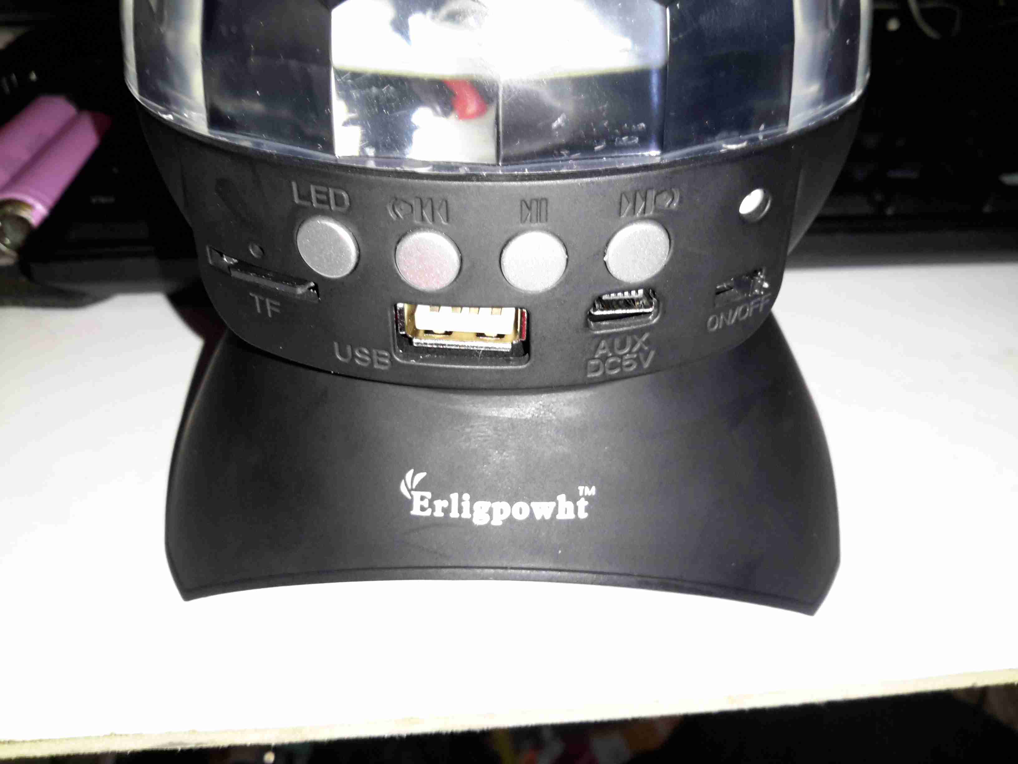
MP3 Disco Light
This device simply oozes cheapness. The large 4″ plastic dome lens sits on the top above the cheap plastic moulding as a base, which also contains the MP3 player speaker.
Controls
There are few controls on this player, the volume buttons are combined with the skip track buttons, a long press operates the volume control, while a short press skips the tracks. Several options for getting this thing to play music are provided:
Bluetooth – Allows connection from any device for bluetooth audio
USB – Plugging in a USB flash drive with MP3 files
SD Card – Very similar to the USB flash drive option, just a FAT32 formatted card with MP3 files
Aux – There’s no 3.5mm jack on this unit for an audio input, instead a “special” USB cable is supplied that is both used to charge the built in battery & feed an audio signal. This is possible since the data lines on the port aren’t used. But it’s certainly out of the ordinary.
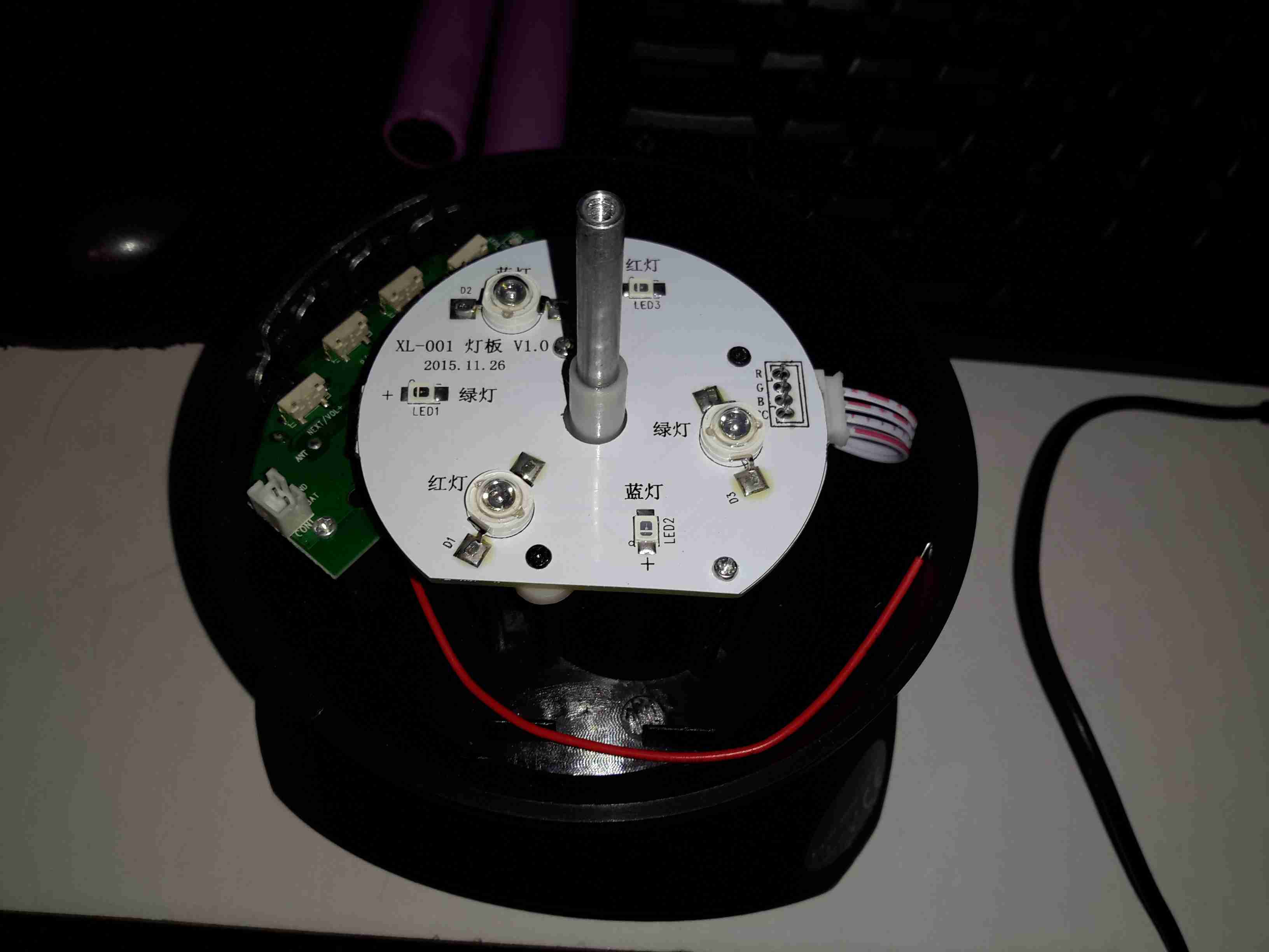
Top Removed
The top comes off with the removal of a single screw in the centre of the lens. The shaft in the centre that holds the lens is attached to a small gear motor under the LED PCB. There’s 6 LEDs on the board, to form an RGB array. Surprisingly for a very small battery powered unit these are bright to the point of being utterly offensive.
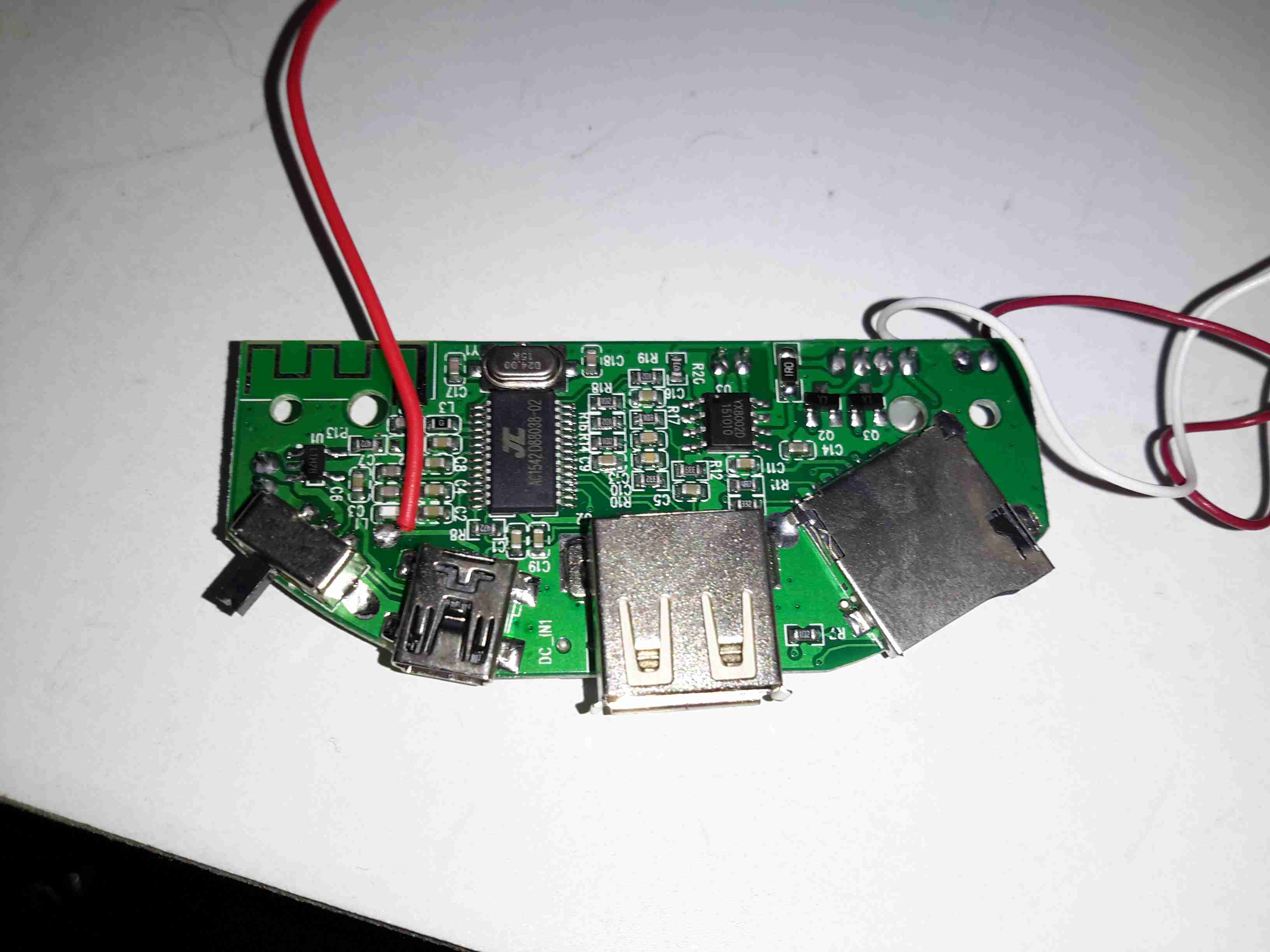
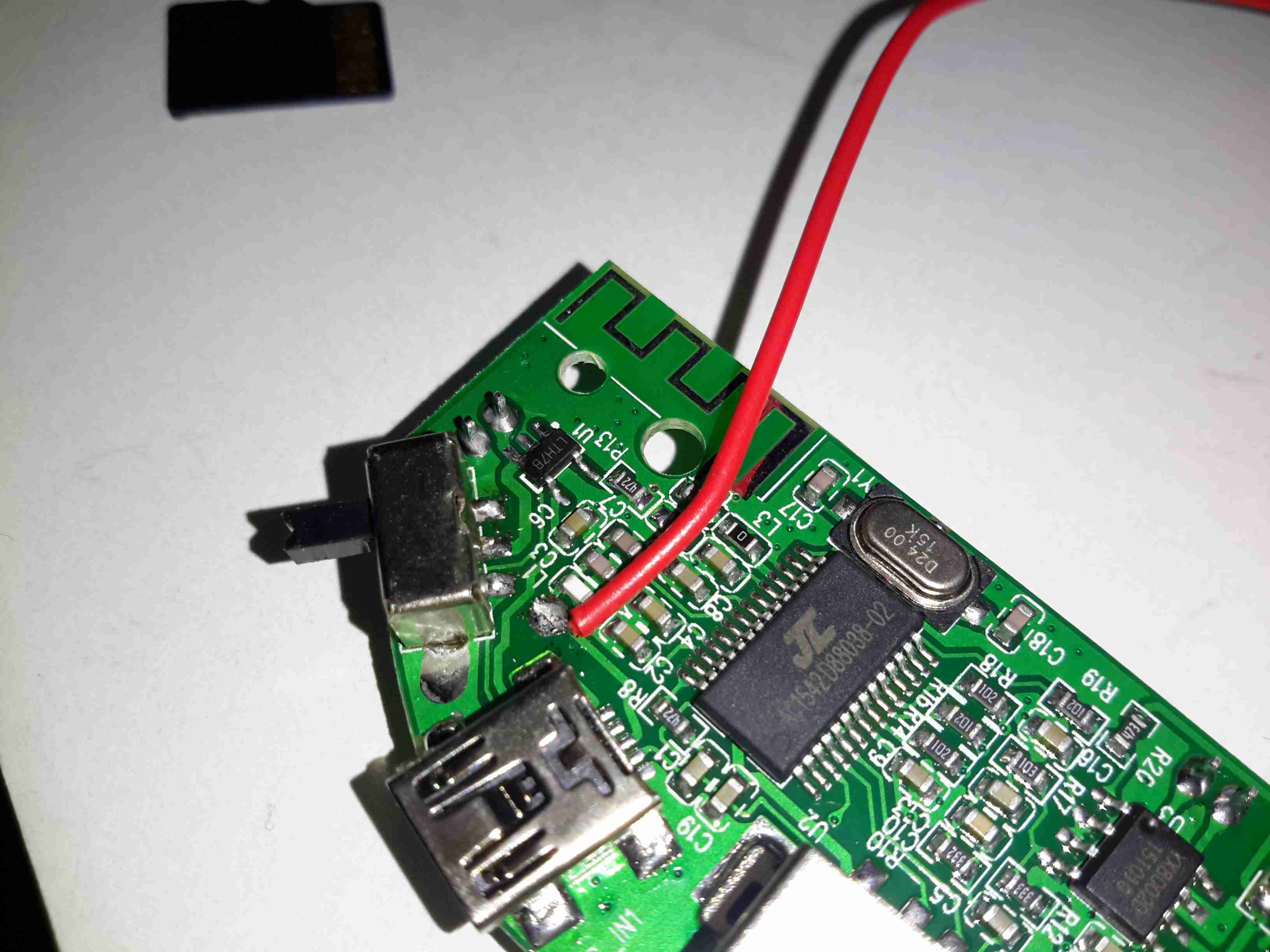
Mainboard
Here’s the mainboard removed from the plastic base. There’s not much to this device, even with all the options it has. The power switch is on the left, followed by the Mini-B USB charging port & aux audio input. The USB A port for a flash drive is next, finishing with the µSD slot. I’m not sure what the red wire is for on the left, it connects to one of the pins on the USB port & then goes nowhere.
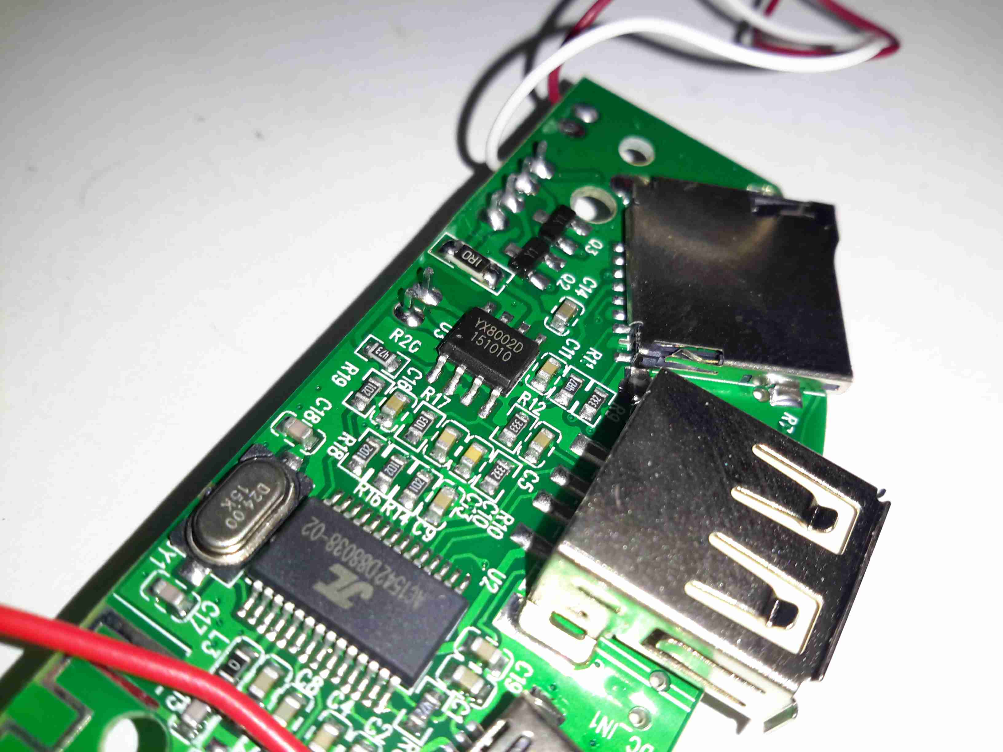
Audio Amplifier
The audio amplifier is a YX8002D, I couldn’t find a datasheet for this, but it’s probably Class D.
Main Chipset
Finally there’s the main IC, which is an AC1542D88038. I’ve not been able to find any data on this part either, it’s either a dedicated MP3 player with Bluetooth radio built in, or an MCU of some kind.The RF antenna for the Bluetooth mode is at the top of the board.
Just behind the power switch is a SOT23-6 component, which should be the charger for the built in Lithium Ion cell.
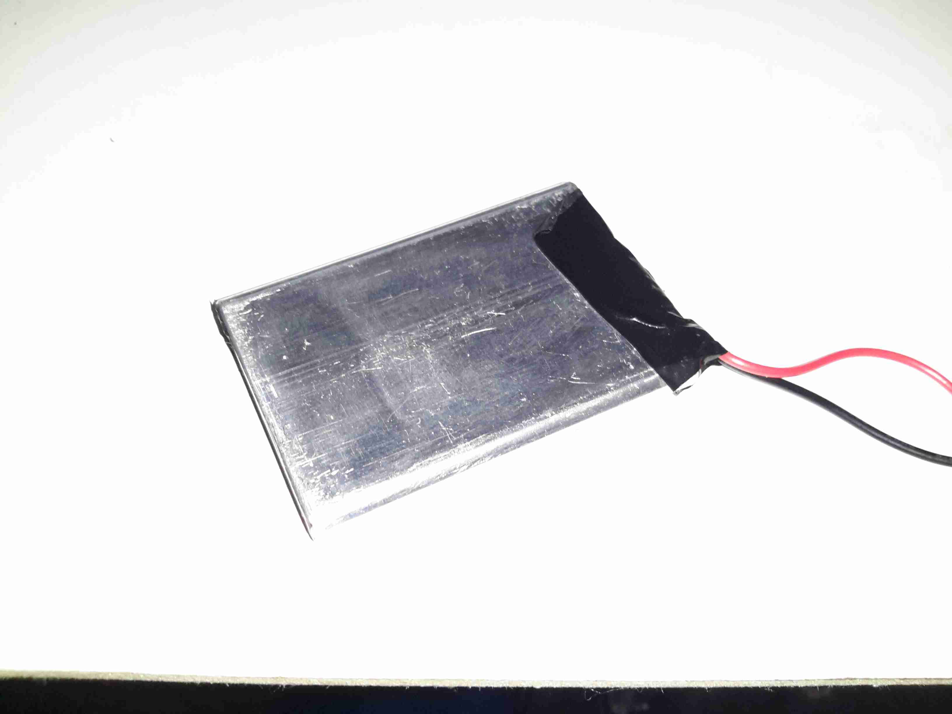
Lithium Ion Cell
The cell itself is a prismatic type rated in the instructions at 600mAh, however my 1C discharge test gave a reading of 820mAh, which is unusual for anything Li-Ion based that comes from eBay 😉
There is cell protection provided, it’s under the black tape on the end, nothing special here.
The main issue so far with this little player is the utterly abysmal battery life – at full volume playing MP3s from a SD card, the unit’s current draw is 600mA, with the seizure & blindness-inducing LEDs added on top, the draw goes up to about 1200mA. The built in charger is also not able to keep up with running the player while charging. This in all only gives a battery life of about 20 minutes, which really limits the usability of the player.
With the installation of the new diesel fired heater we’ve noticed a small problem – since the only heat source in the saloon is the stove, even with the diesel heater fired up the temperature doesn’t really change much, as the heat from the radiators in the both the cabins & the head isn’t spreading far enough.
The solution to this problem is obviously an extra radiator in the saloon, however there isn’t the space to fit even a small domestic-style radiator. eBay turned up some heater matrix units designed for kit cars & the like:
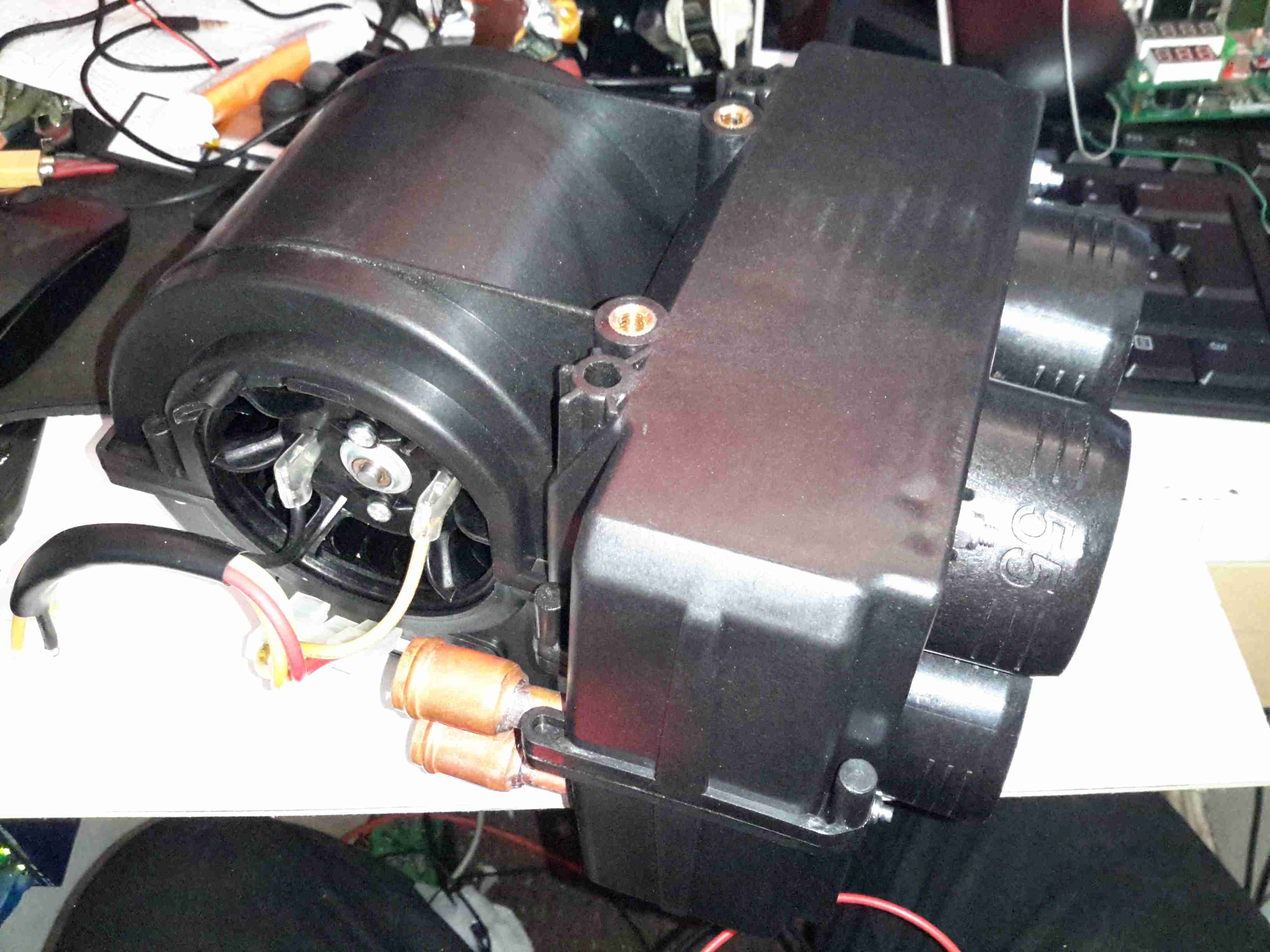
3.8kW Matrix
These small heater matrix units are nice & compact, so will fit into the back of a storage cupboard next to the saloon. Rated at a max heat output of 3.8kW, just shy of the stove’s rated 4kW output power, this should provide plenty of heating when we’re running the diesel heater rather than the fire.
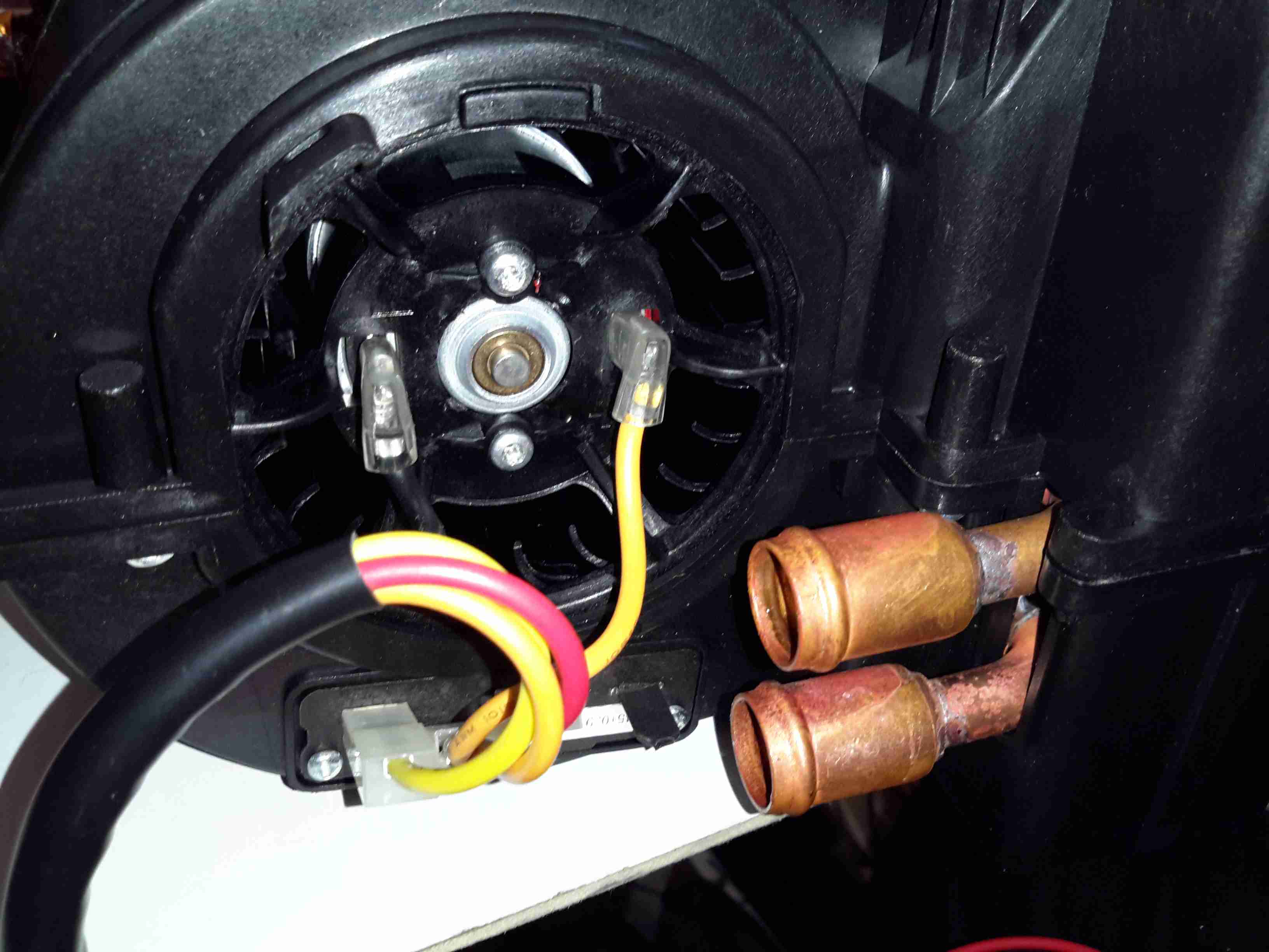
Water & Power
The blower motor has a resistor network to provide 3 speeds, but this probably won’t be used in this install, water connections are via 15mm copper tails. The current plan is to use a pipe thermostat on the flow from the boiler to switch on the blower when the water temperature reaches about 40°C.
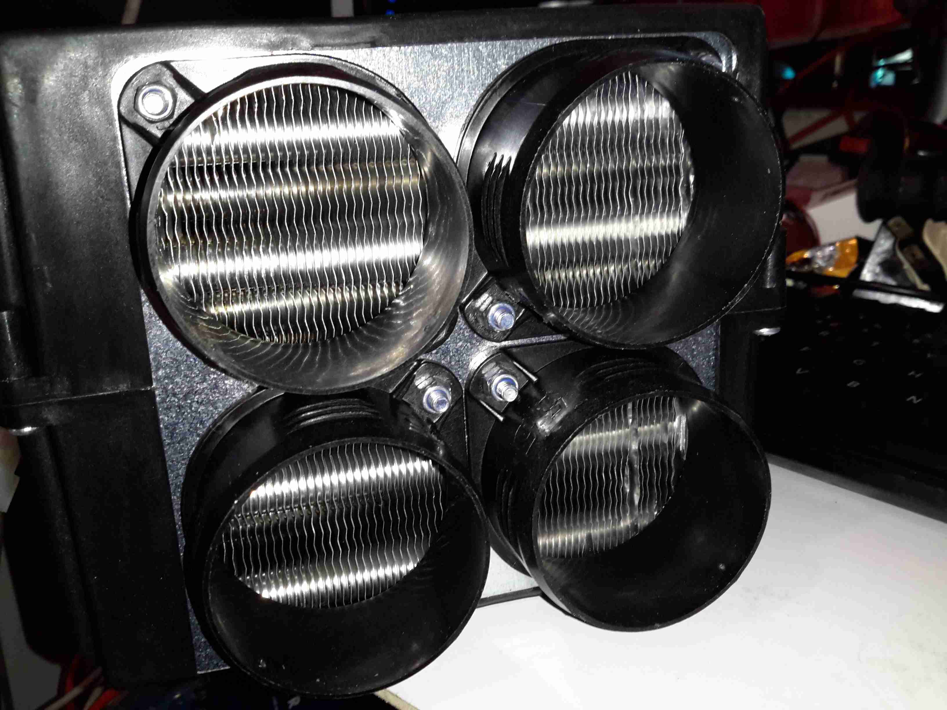
Hot Air Outlets
The hot air emerges from the matrix via 4 55mm duct sockets. This gives enough outlets to cover both the saloon & the corridor down to the cabins.
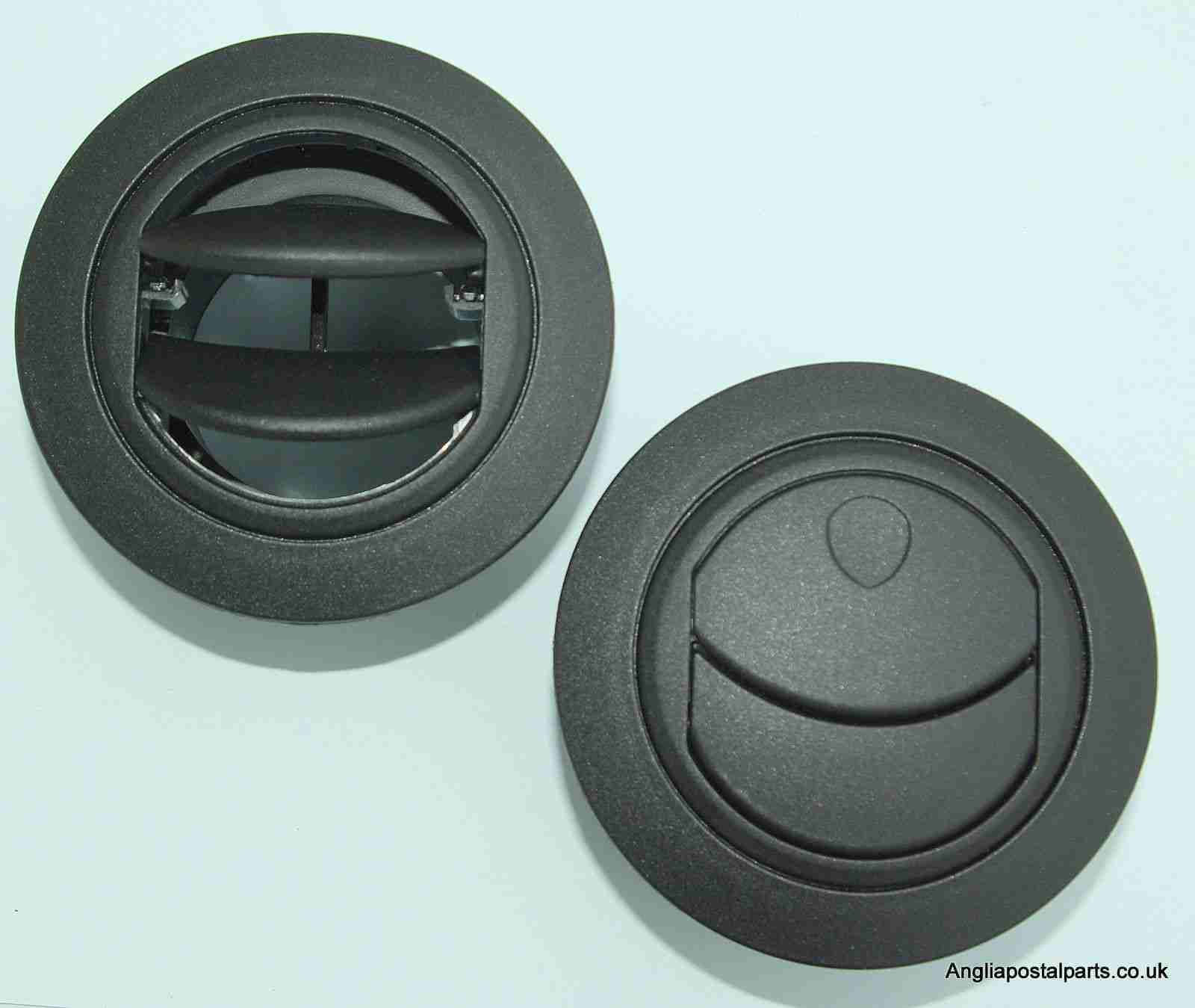
Hot Air Vents
Standard 60mm Eberspacher style vents will be used to point the warmth where it’s needed.
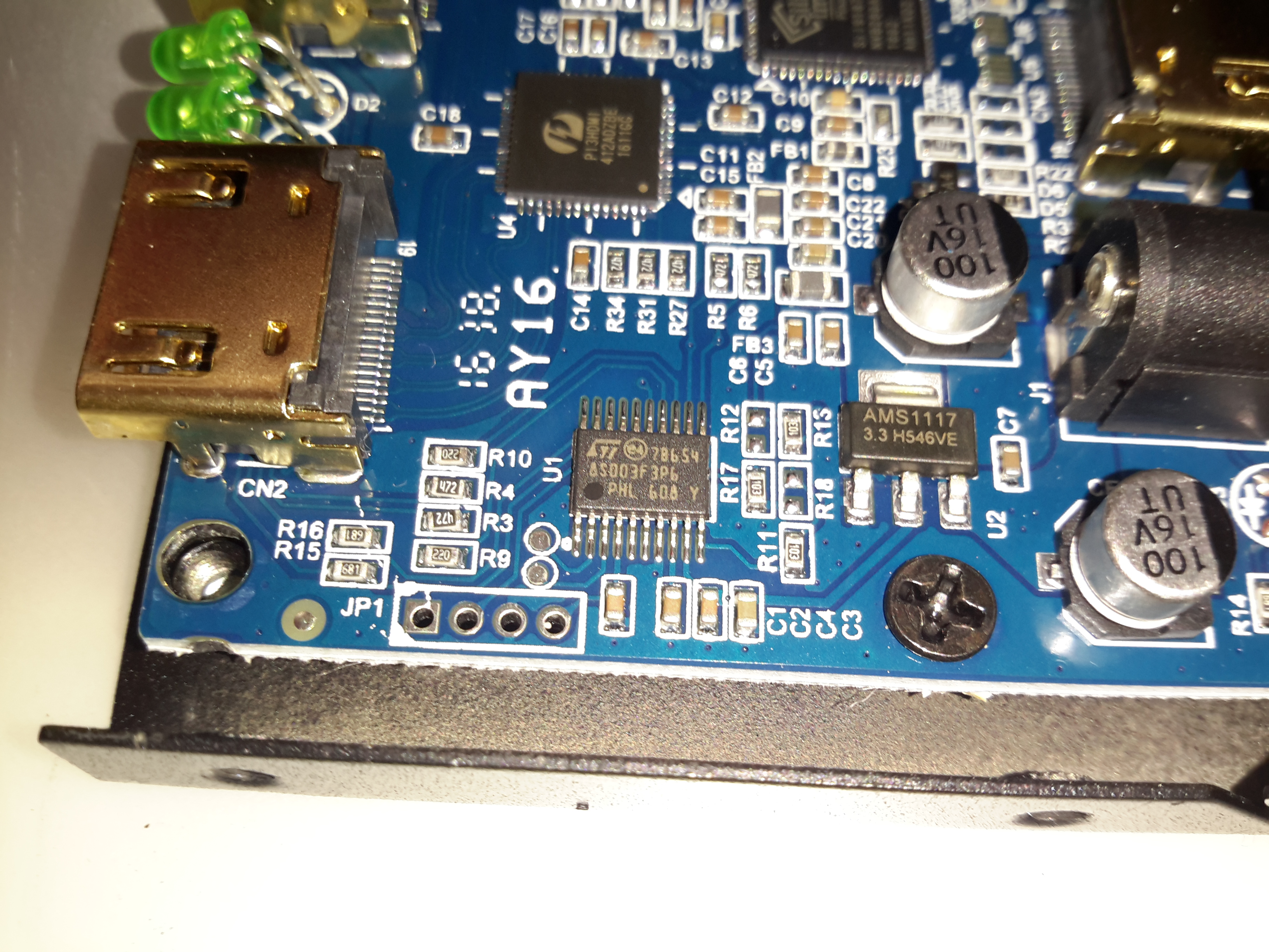
Time for another random teardown, a signal splitter for HDMI. These units are available very cheap these days on eBay. This one splits the incoming signal into two to drive more than one display from the same signal source.
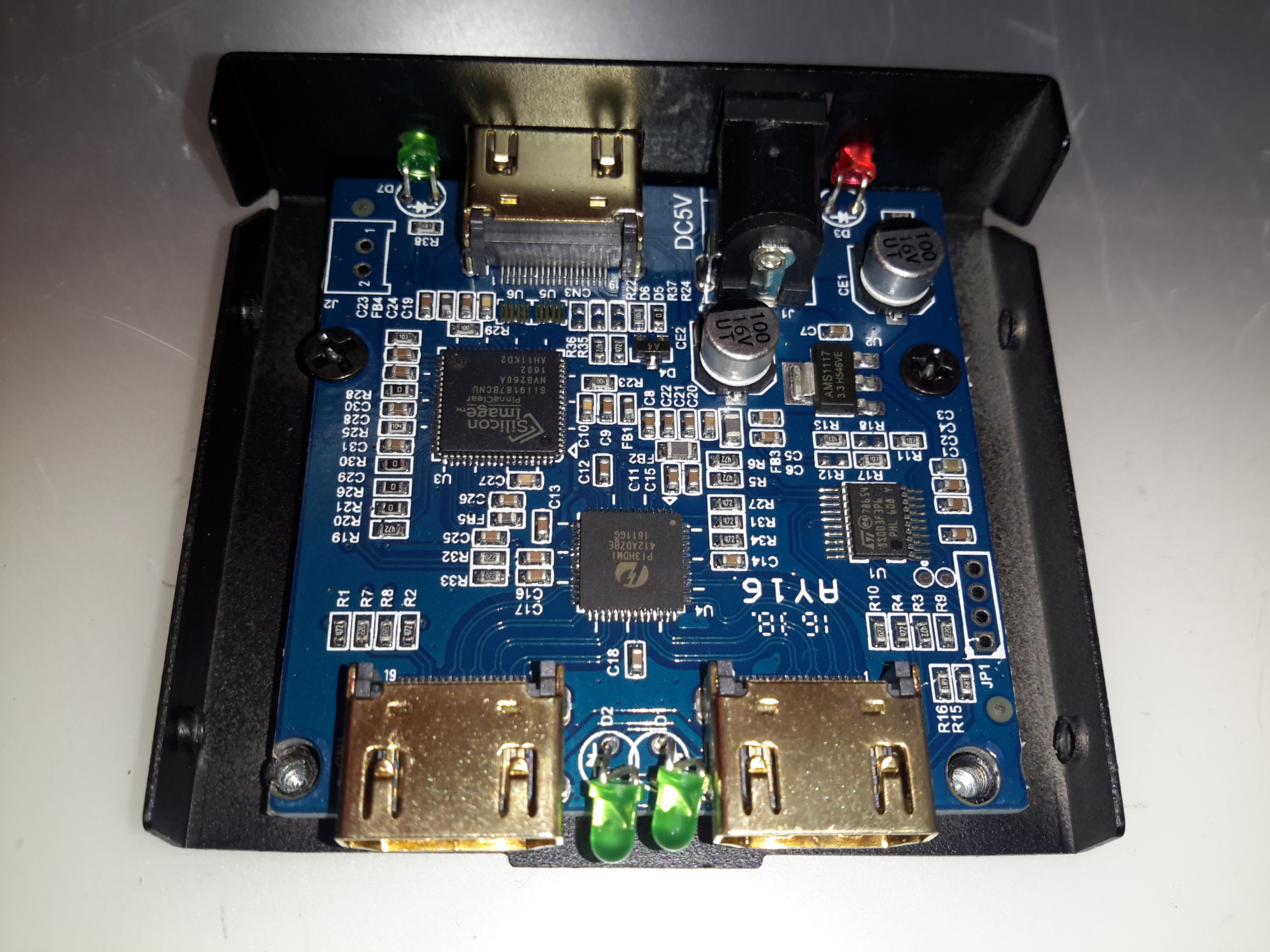
Main PCB
The stamped alloy casing comes apart easily with the removal of a few screws. The PCB inside is rather densely packed with components.
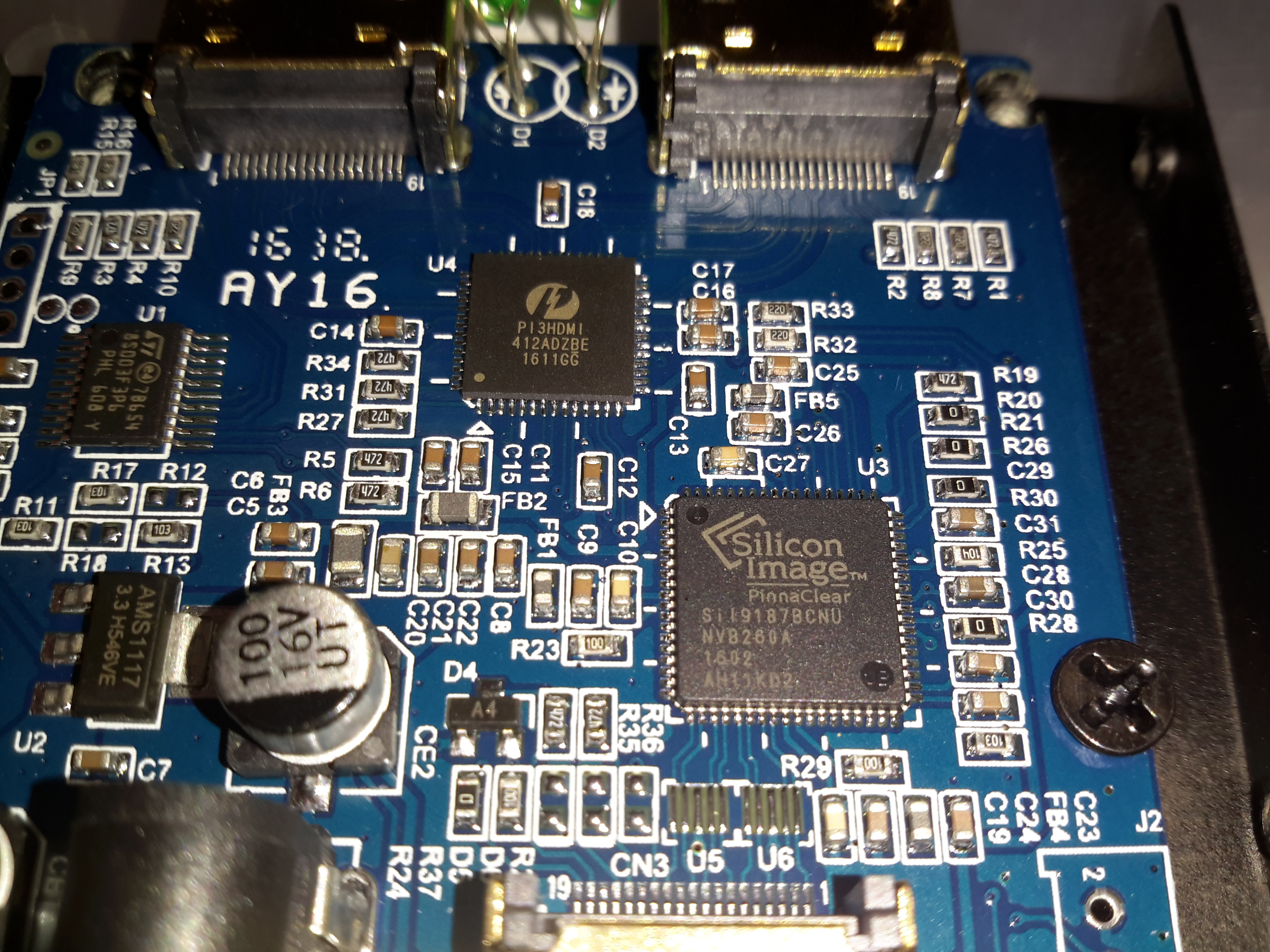
Chipset
The main IC on the incoming signal is a Silicon Image Sil9187B HDMI Port Processor, with a single input & 4 outputs. In this case the chip is used as a repeater to amplify the incoming signal. the signal path then gets fed into a Pericom PI3HDMI412 HDMI Demux, which then splits the signal into two for the output ports.
Microcontroller
The main pair of ICs processing the video signals are controlled over I²C, with this STM32 microcontroller. The 4 pads to the lower left are for the STLink programmer. The main 3.3v power rail is provided by the LM1117 linear regulator on the right.
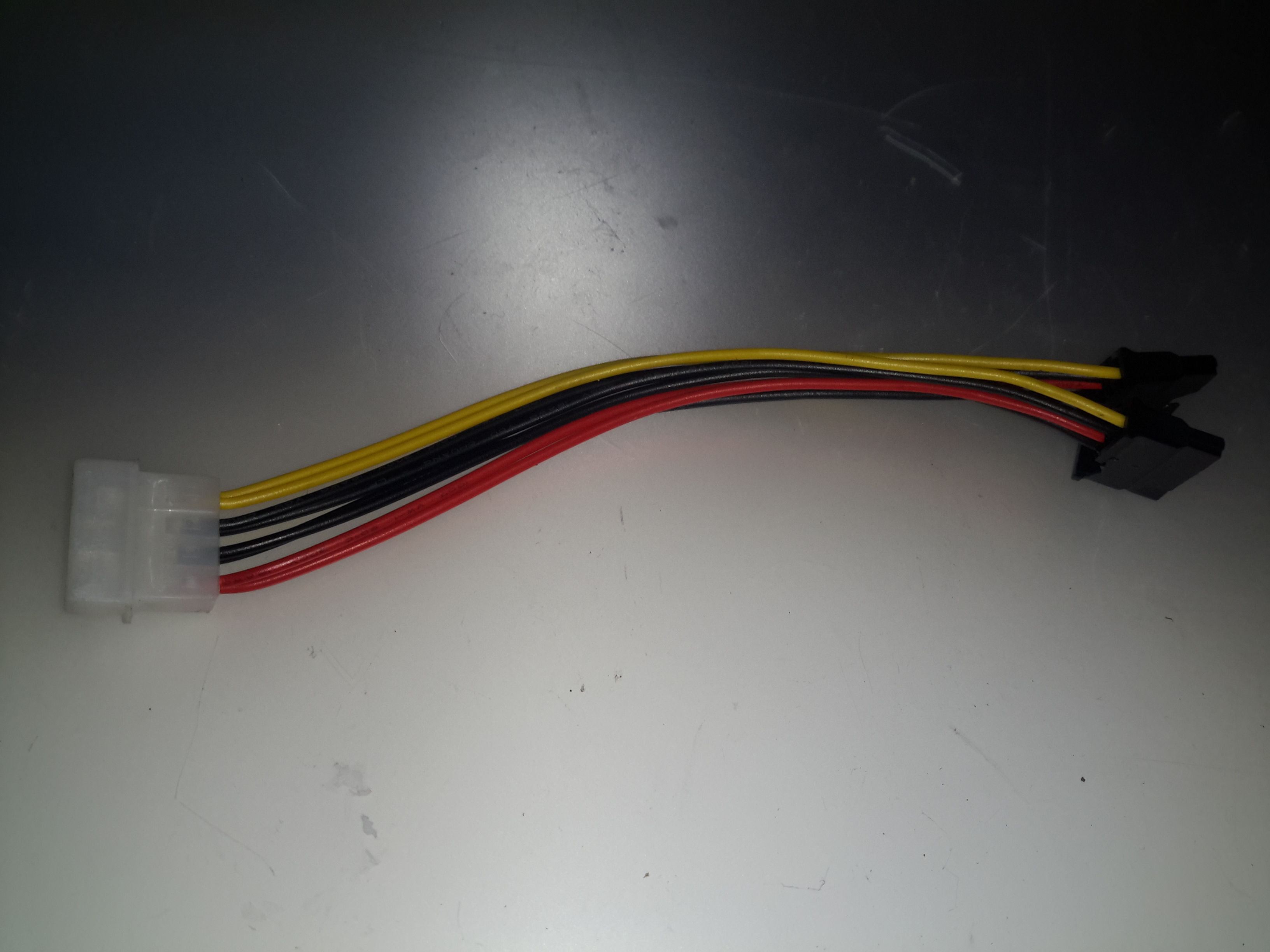
To do some upgrades to my NAS, I needed some SATA power adaptors, to split the PSU out to the planned 16 disk drives. eBay has these for very little money, however there’s a good reason for them being cheap.
Wire Marking
The marking on the wire tells me it’s 18AWG, which should be good for 9.5A at an absolute maximum. However these adaptors are extremely light.
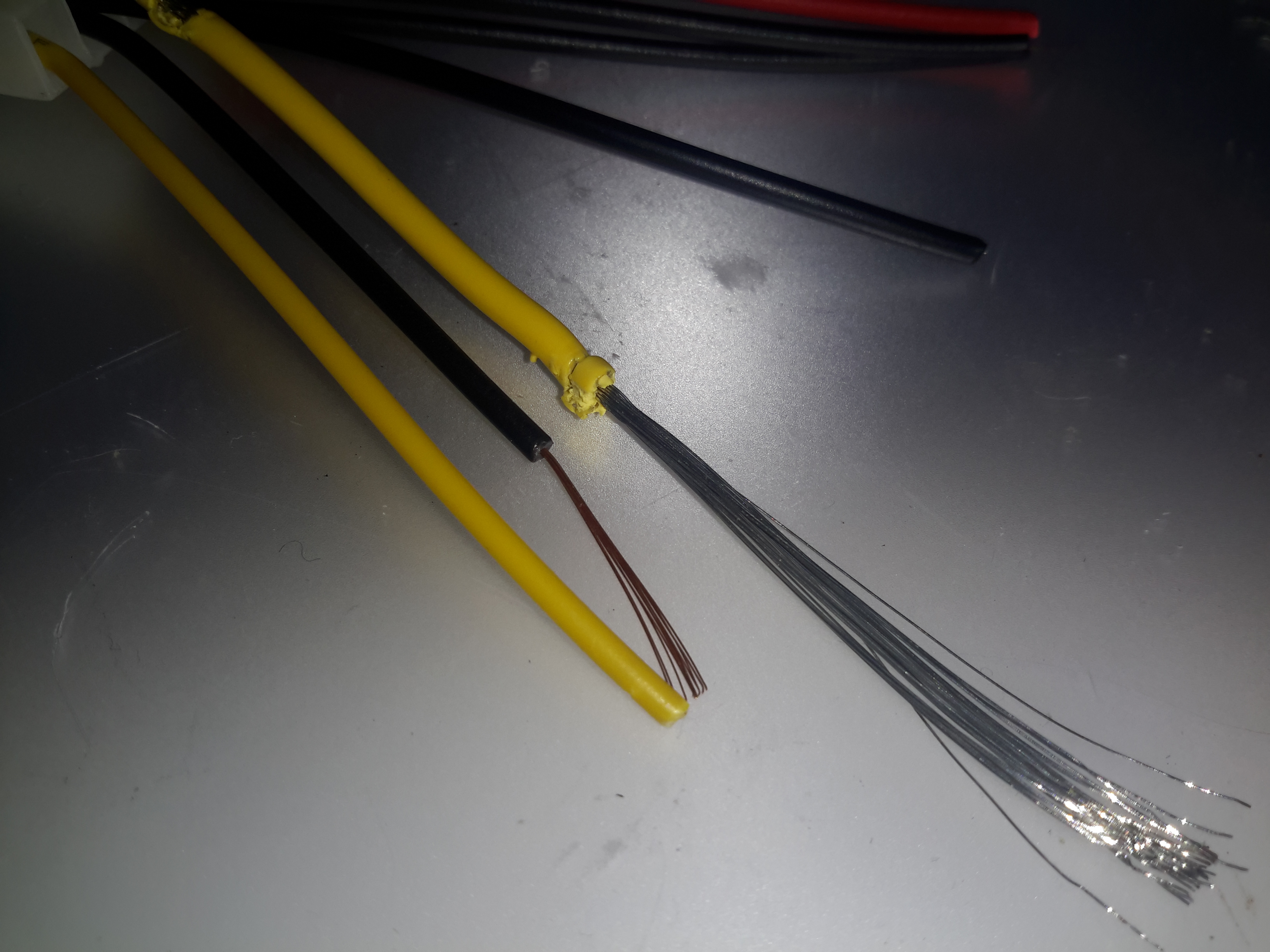
Wire Comparison
Here’s the cheapo eBay wire compared to proper 18AWG wire. The cores in the eBay adaptor are tiny, I’d guess about 24AWG, only good for about 3A. As disk drives pull about 2A from the +12v rail on startup to spin the platters up to speed, this thin wire is going to cause quite the volt drop & possibly prevent the disk from operating correctly.
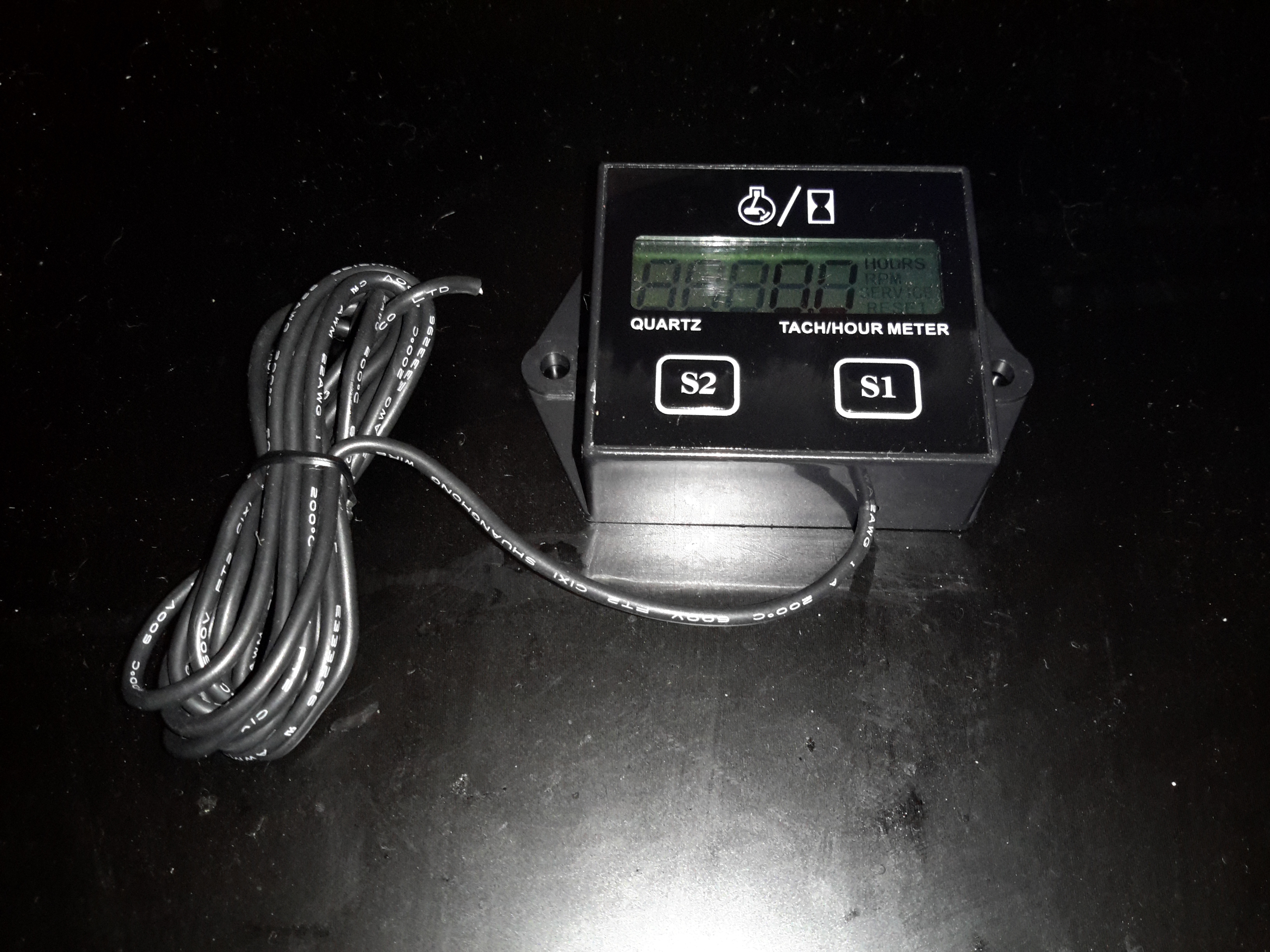
As one of my current projects involves a small petrol engine – a Honda GX35 clone, I figured an hour counter would be very handy to keep an eye on service intervals. (More to come on the engine itself later on). I found a device that would suit my needs on good old eBay.
Inductive Engine Monitor
These engine monitors are pretty cheap, at about £4. The sensing is done by a single heat-resistant silicone wire, that wraps around the HT lead to the spark plug. The unit can be set for different firing intervals via the buttons. In the case of most single-cylinder 4-stroke engines, the spark plug fires on every revolution – wasted-spark ignition. This simplifies the ignition system greatly, by not requiring the timing signal be driven from 1/2 crankshaft speed. The second “wasted” spark fires into the exhaust stroke, so has no effect.
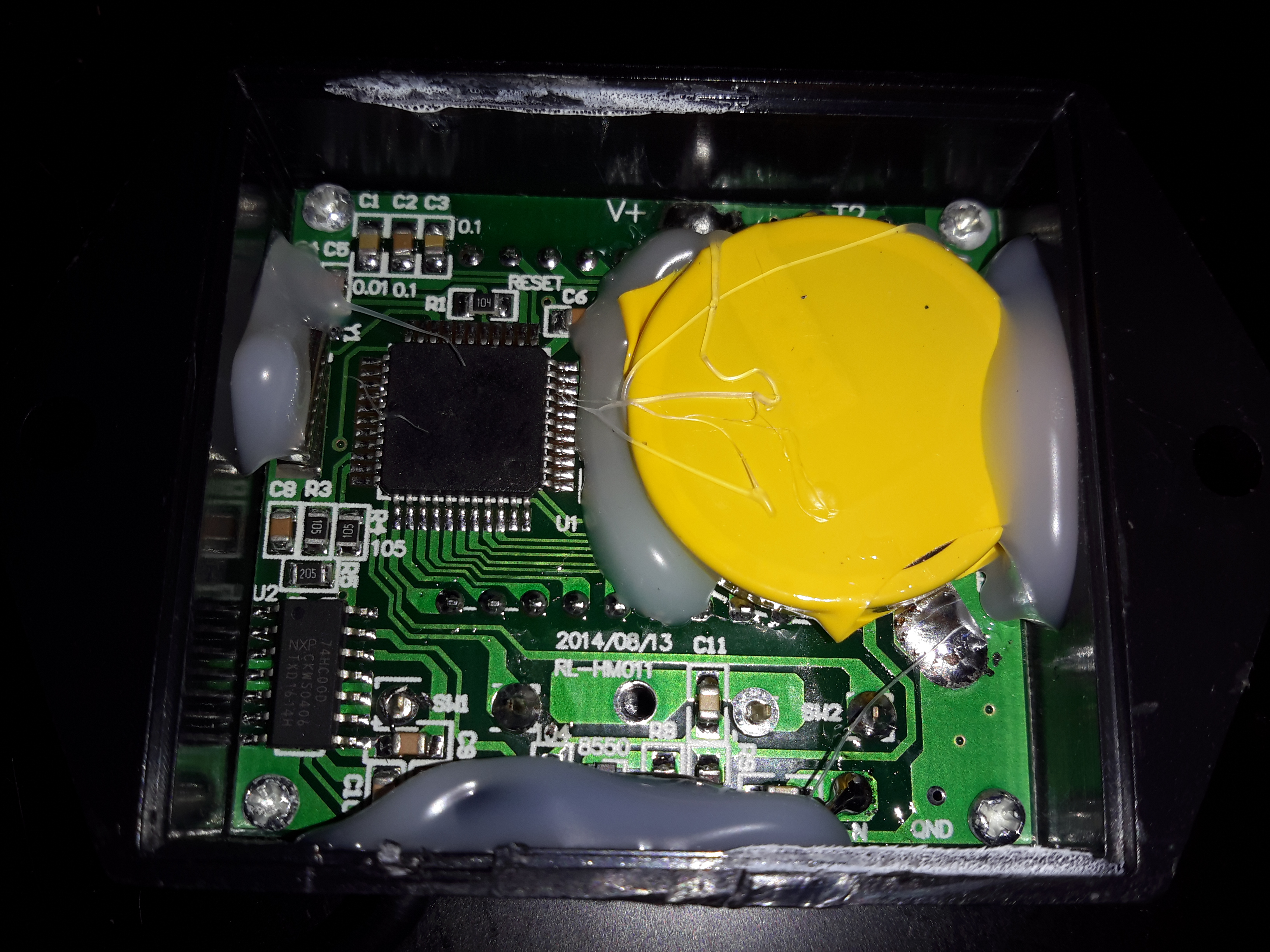
Internals
The back cover is lightly glued into place with a drop of cyanoacrylate in opposite corners, but easily pops off. The power is supplied by a soldered-in 3v Lithium cell. The main microcontroller has no number laser etched on to it at all – it appears it skipped the marking machine.
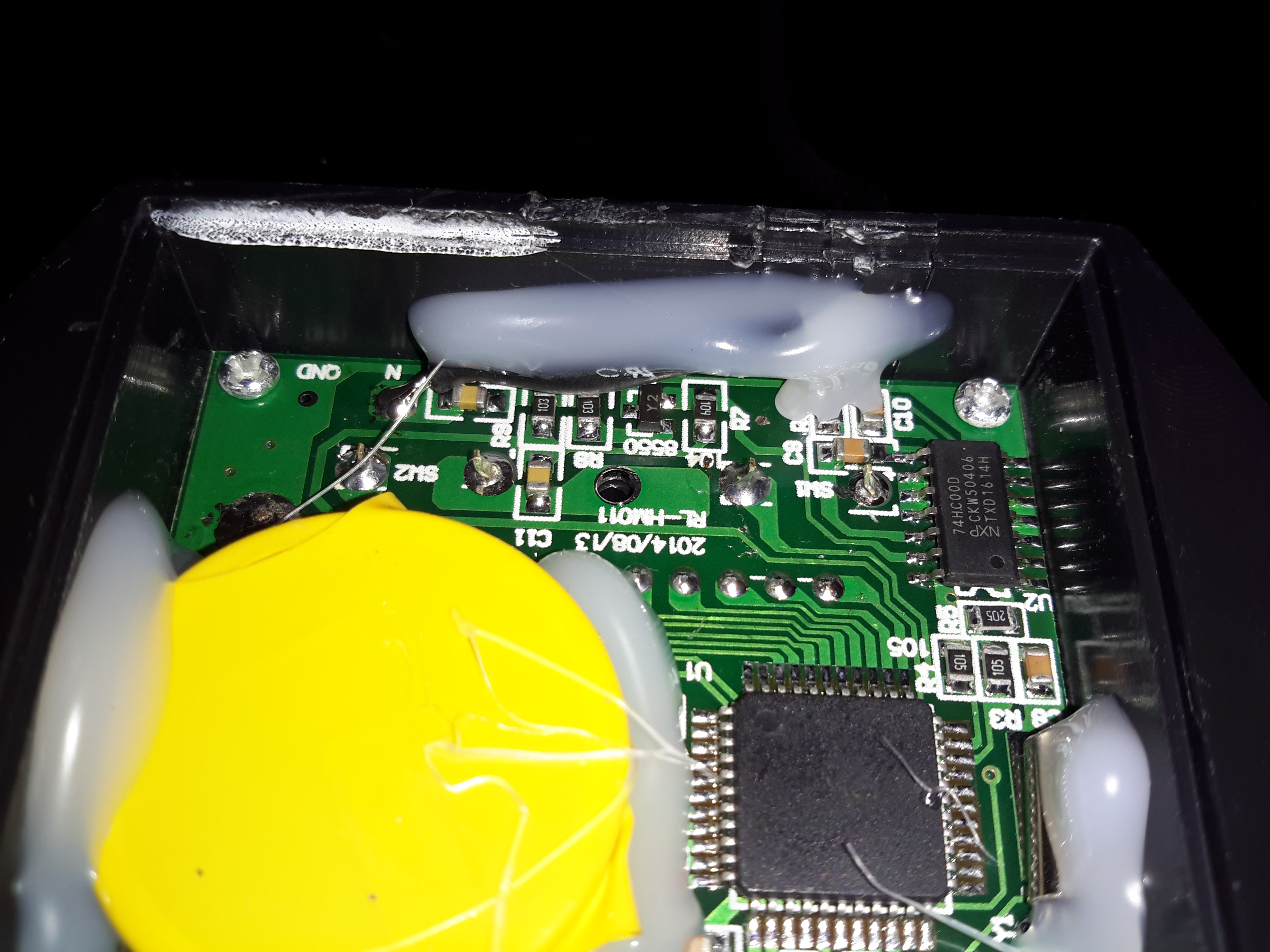
Input Filtering
The input from the sensing wire comes in through a coupling capacitor & is amplified by a transistor. It’s then fed into a 74HC00D Quad 2-Input NAND gate, before being fed into the microcontroller.
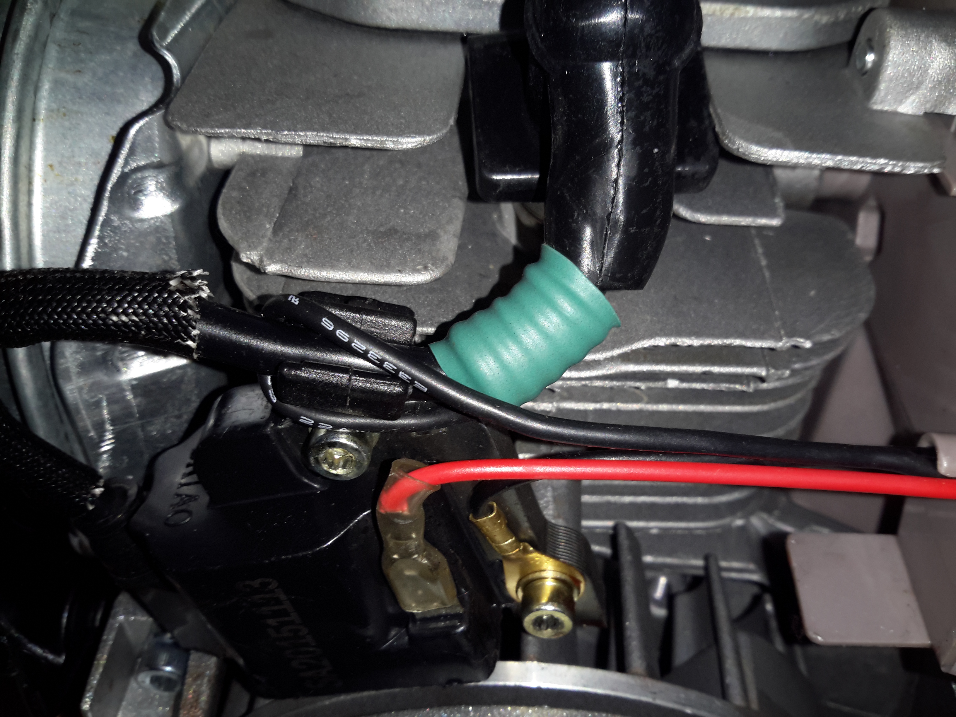
Pickup
The pickup wire is simply wound around the spark plug lead. I’ve held it in position here with some heatshrink tubing. Heat in this area shouldn’t be an issue as it’s directly in the airflow from the flywheel fan.
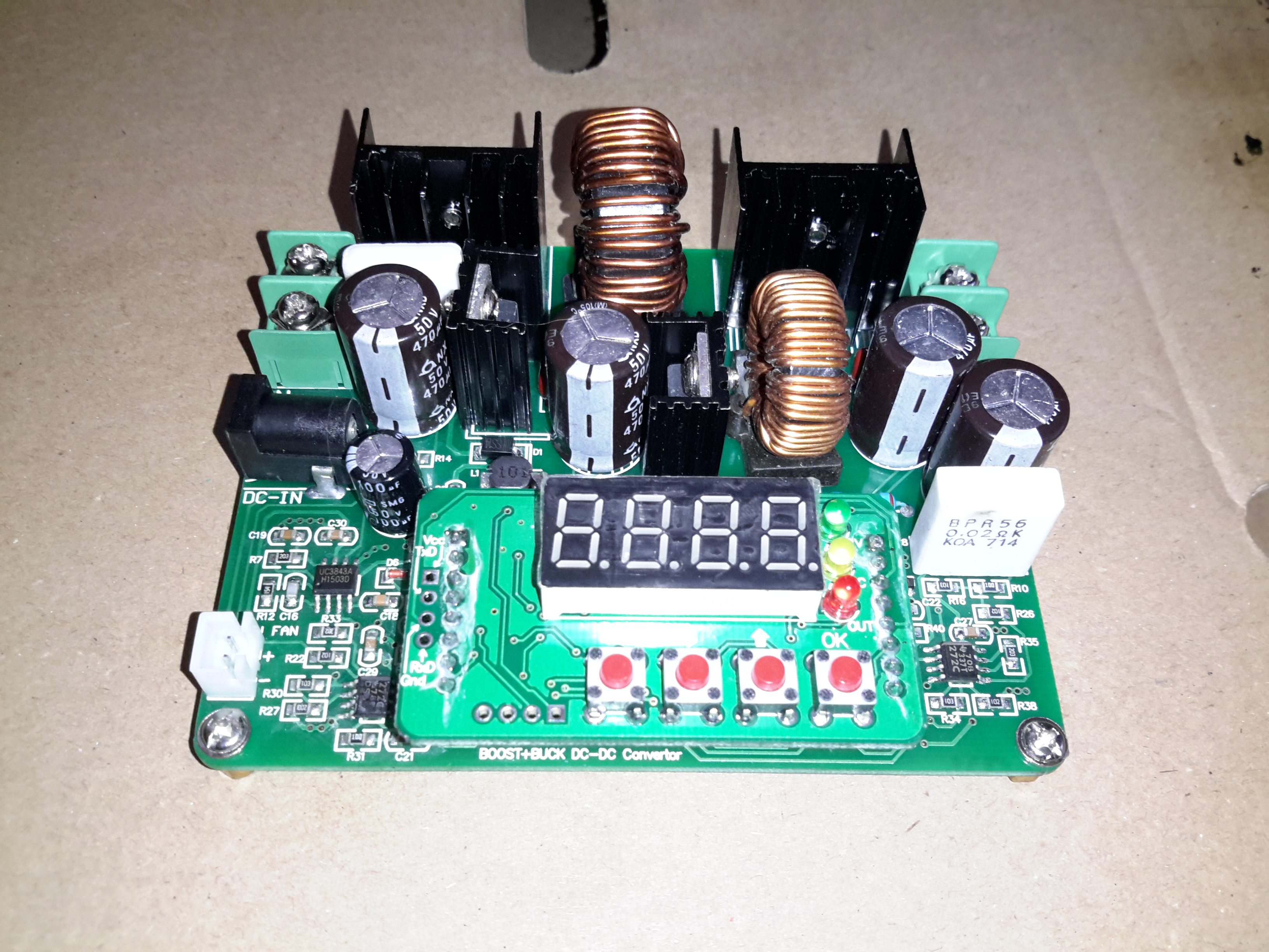
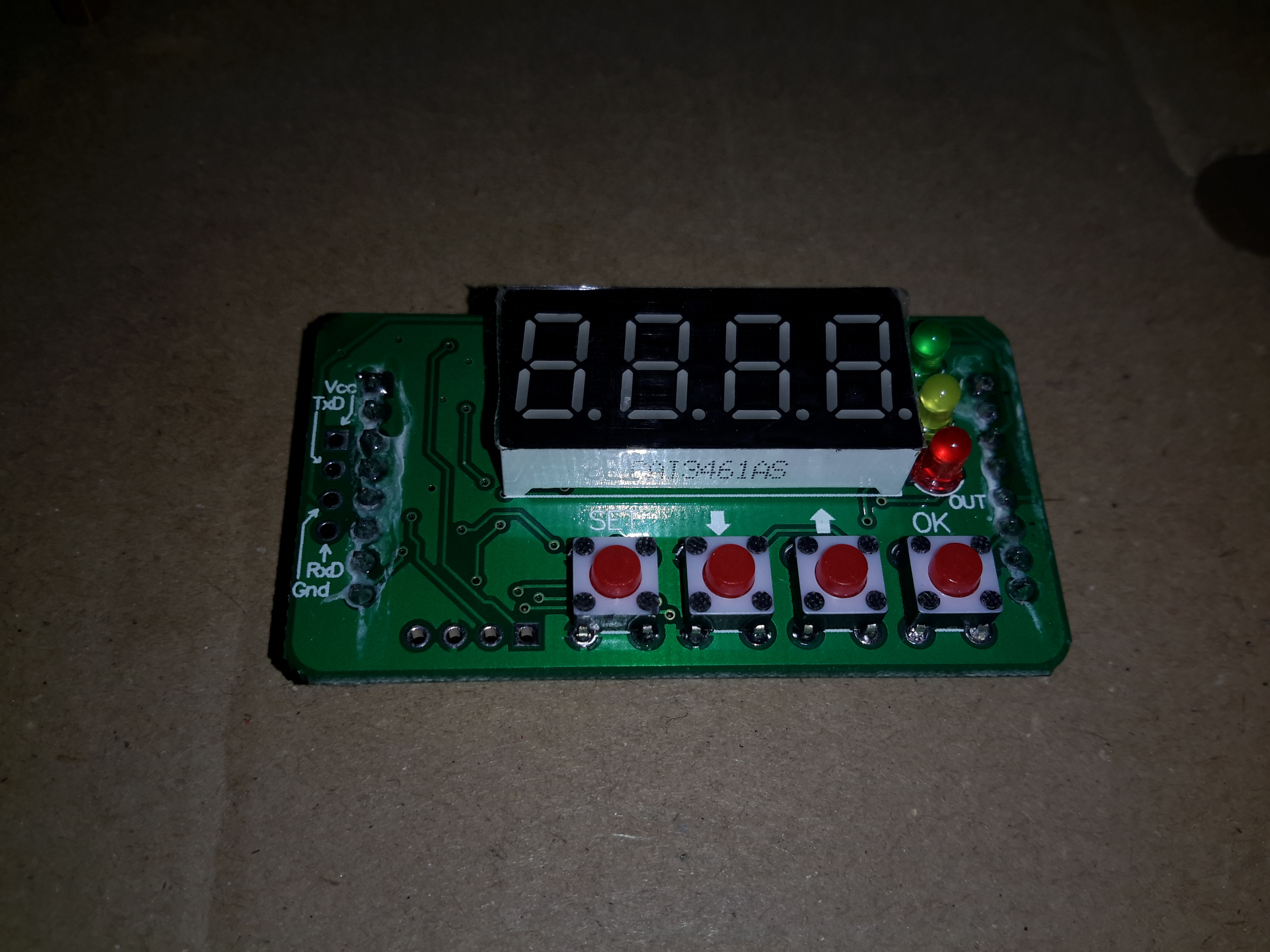
Here’s a useful buck-boost DC-DC converter from eBay, this one will do 36v DC at 6A maximum output current. Voltage & current are selected on the push buttons, when the output is enabled either the output voltage or the output current can be displayed in real time.
Display PCB
Here’s the display PCB, which also has the STM32 microcontroller that does all the magic. There appears to be a serial link on the left side, I’ve not yet managed to get round to hooking it into a serial adaptor to see if there’s anything useful on it.
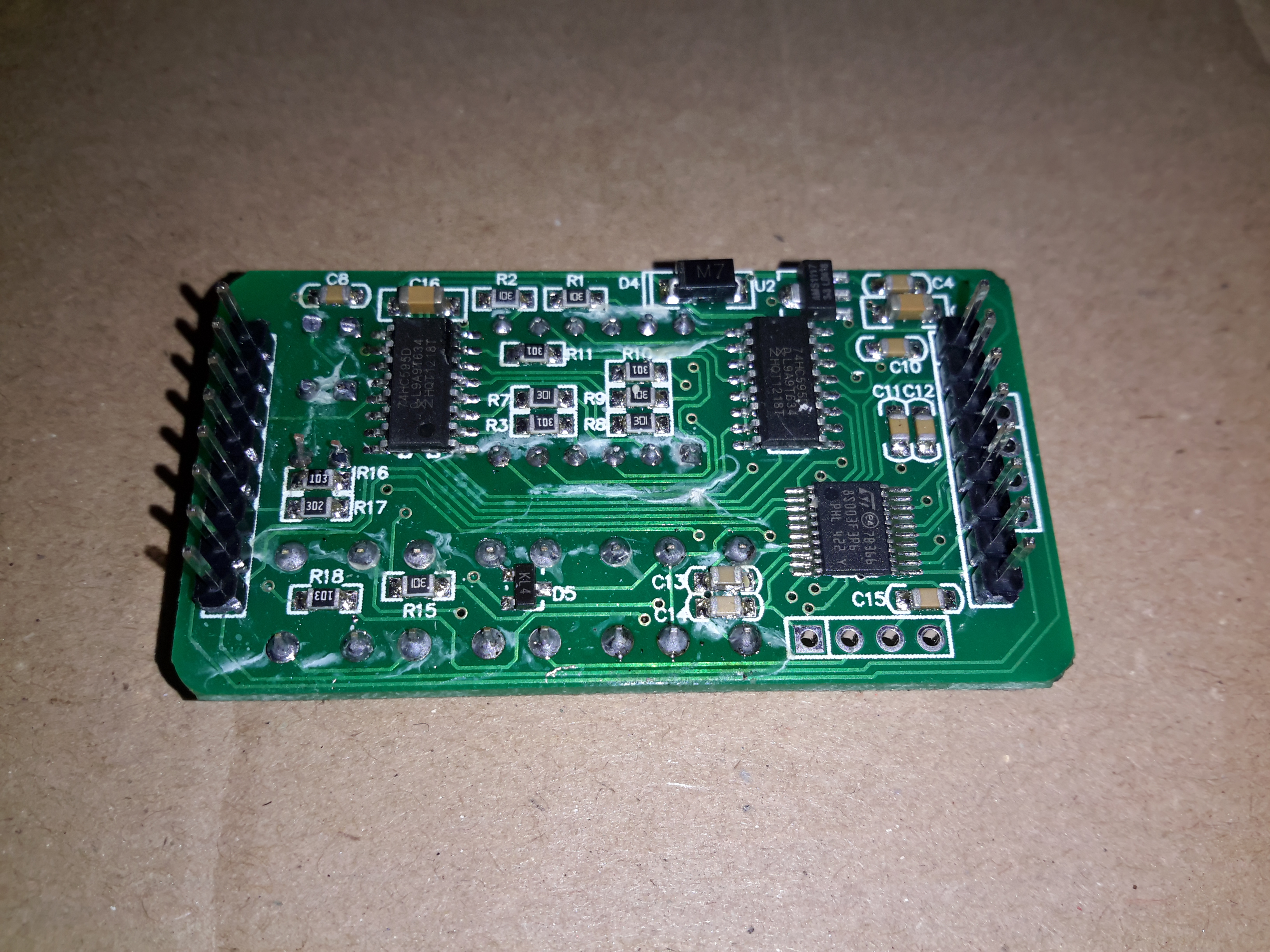
Display Drive & Microcontroller
The bottom of the board holds the micro & the display multiplexing glue logic.
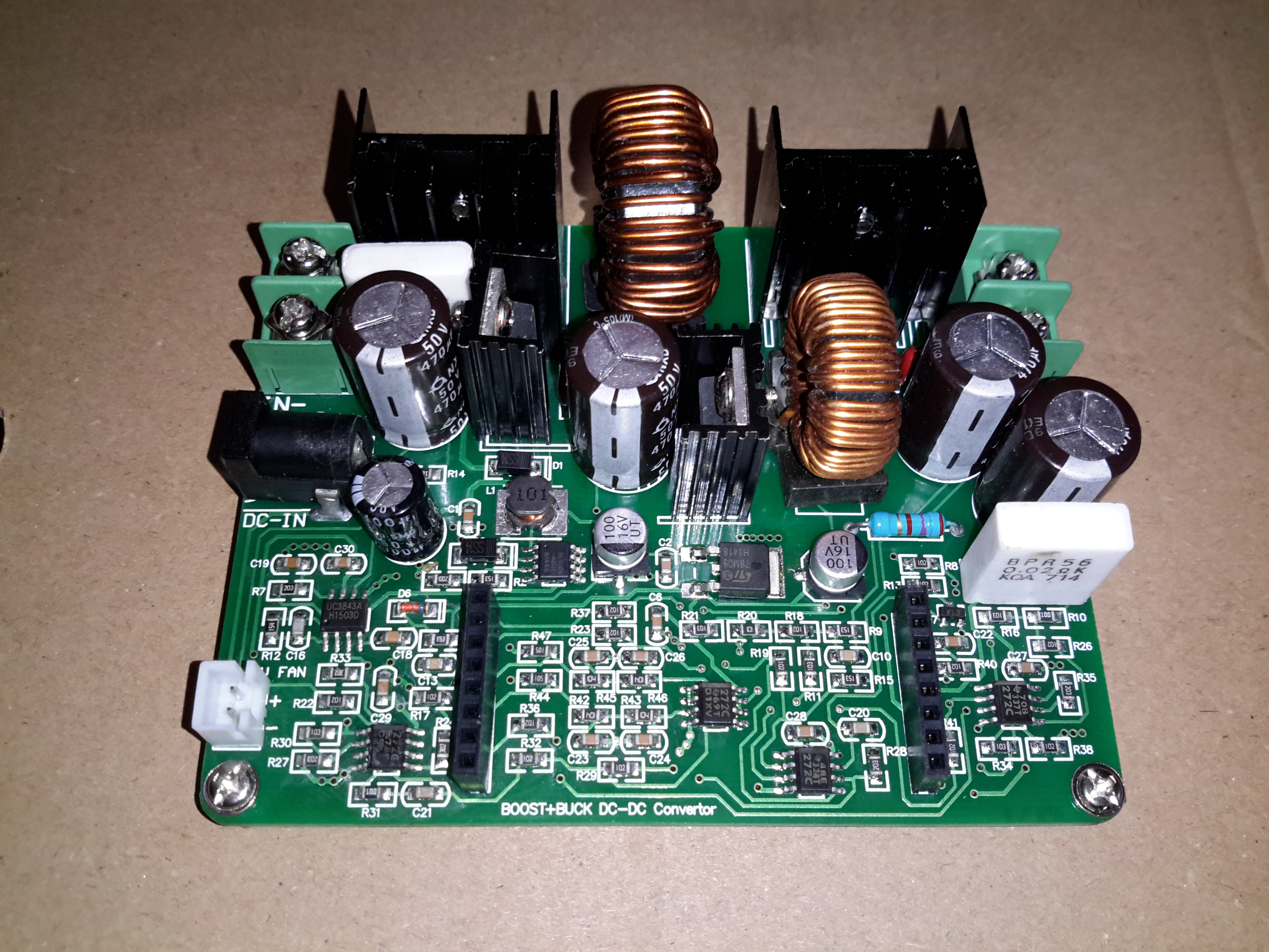
Main PCB
Not much on the mainboard apart from the large switching inductors & power devices. There’s also a SMPS PWM controller, probably being controlled from the micro.
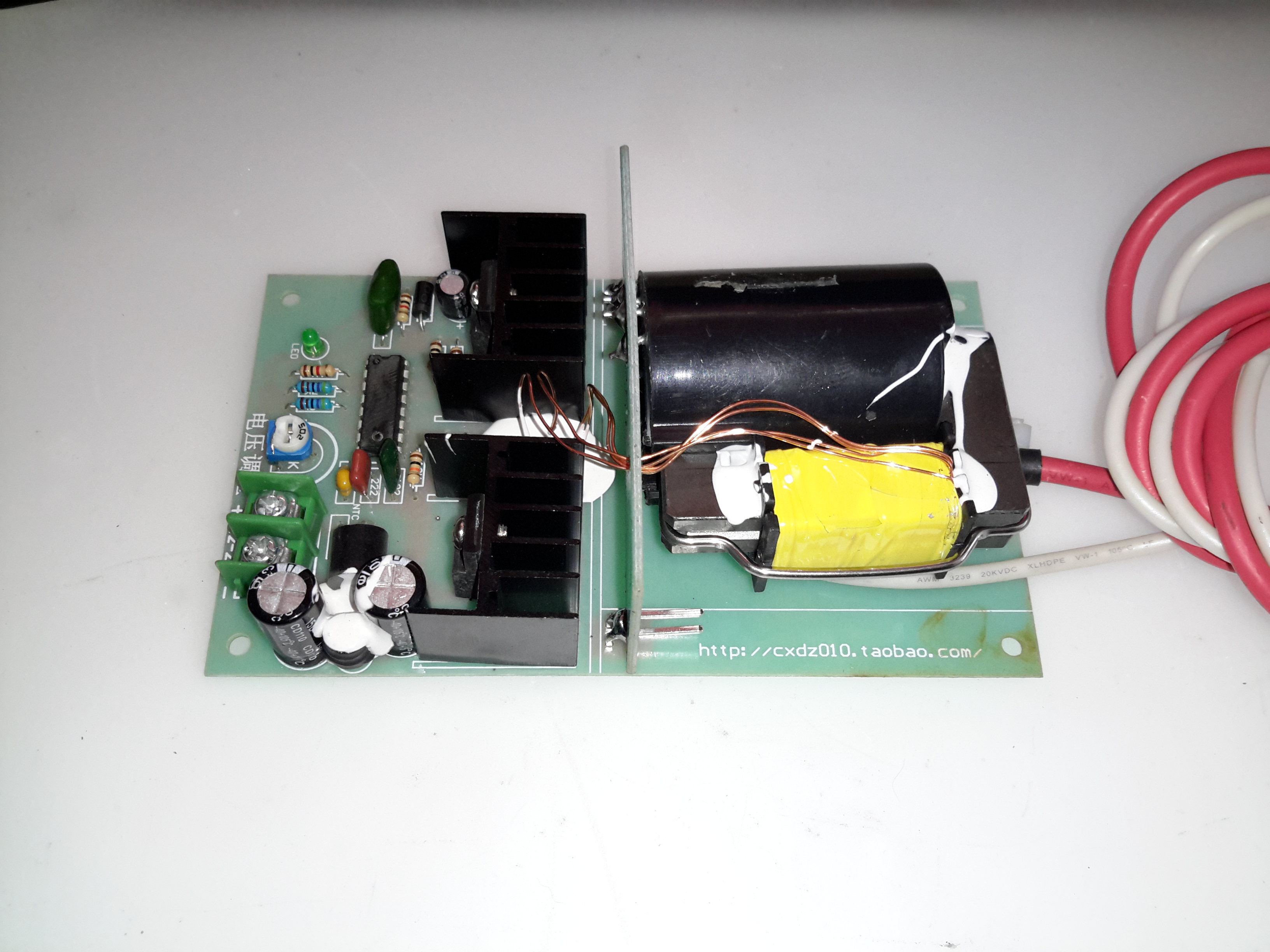
I have found myself needing some more in the way of High Voltage supplies of late, with the acquisition of the new He-Ne laser tubes, so I went trawling eBay for something that would be suitable to run these tubes. (I currently only have a single He-Ne laser PSU brick, and they’re notoriously hard to find & rather expensive).
This supply is rated at 1kV-10kV output, at 35W power level. Unfortunately this supply isn’t capable of sustaining the discharge in a large He-Ne tube, the impedance of the supply is far too high. Still, it’s useful for other experiments.
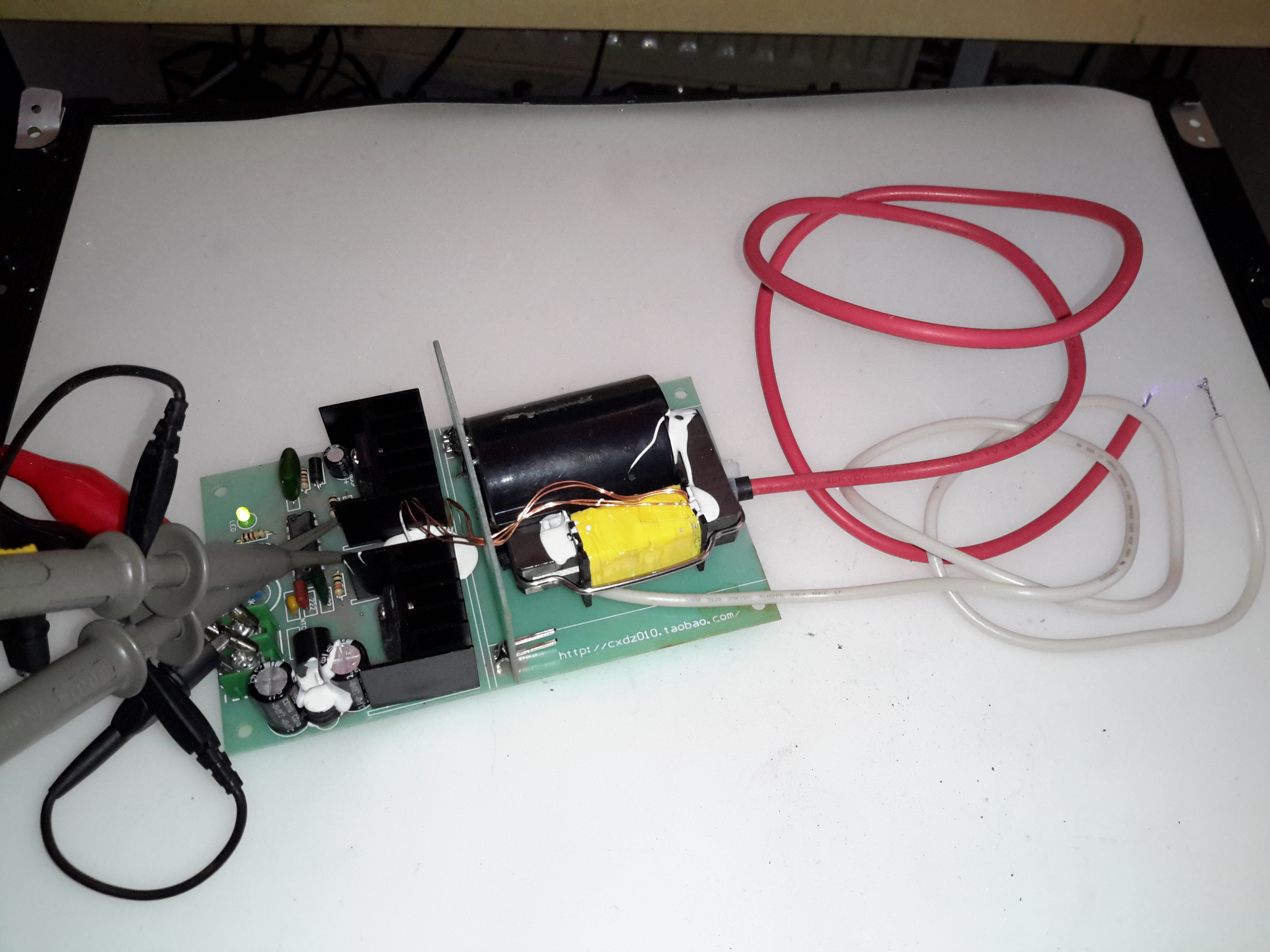
The flyback-type transformer clearly isn’t a surplus device from CRT manufacture, as there are very few pins on the bottom, and none of them connect to the primary side. The primary is separately wound on the open leg of the ferrite core.
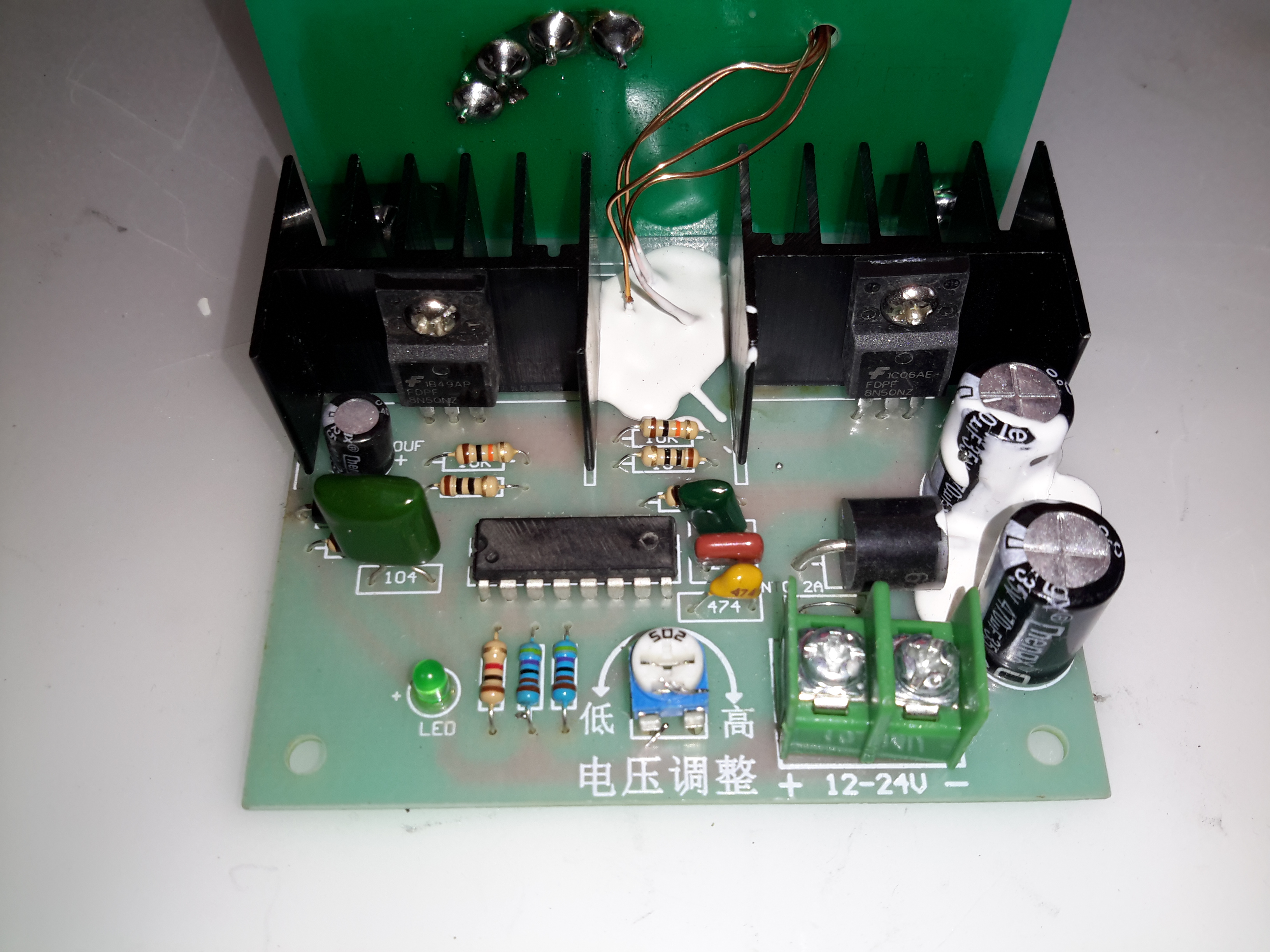
Drive Electronics
The drive electronics are pretty simple, there’s a controller IC (with the number scrubbed off – guessing it’s either a 556 dual timer or a SMPS controller), a pair of FDP8N50NZ MOSFETs driving the centre-tapped primary winding.
The drive MOSFETs aren’t anything special in this case: they’re rated at 500v 8A, 850mΩ on resistance. This high resistance does make them get rather hot even with no load on the output, so for high power use forced-air cooling from a fan would definitely be required.
Test Setup
Here’s the supply on test, I’ve got the scope probes connected to the gate resistors of the drive MOSFETs.
Waveforms
On the scope the primary switching waveforms can be seen. The FETs operate in push-pull mode, there’s a bit of a ring on the waveform, but they’re pretty nice square waves otherwise.
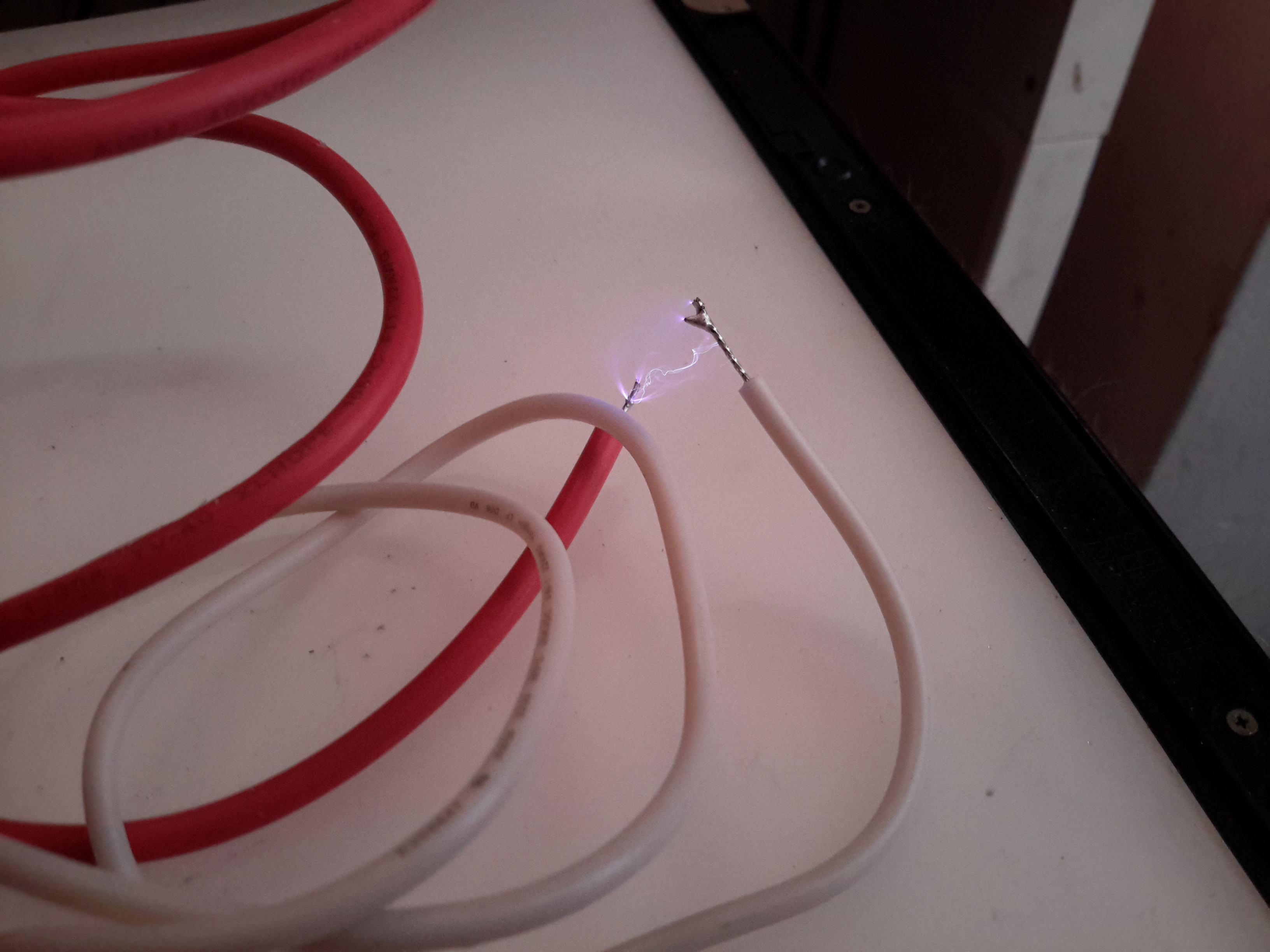
Arc
At maximum power on 12v input, about 25mm of gap is possible with an arc.
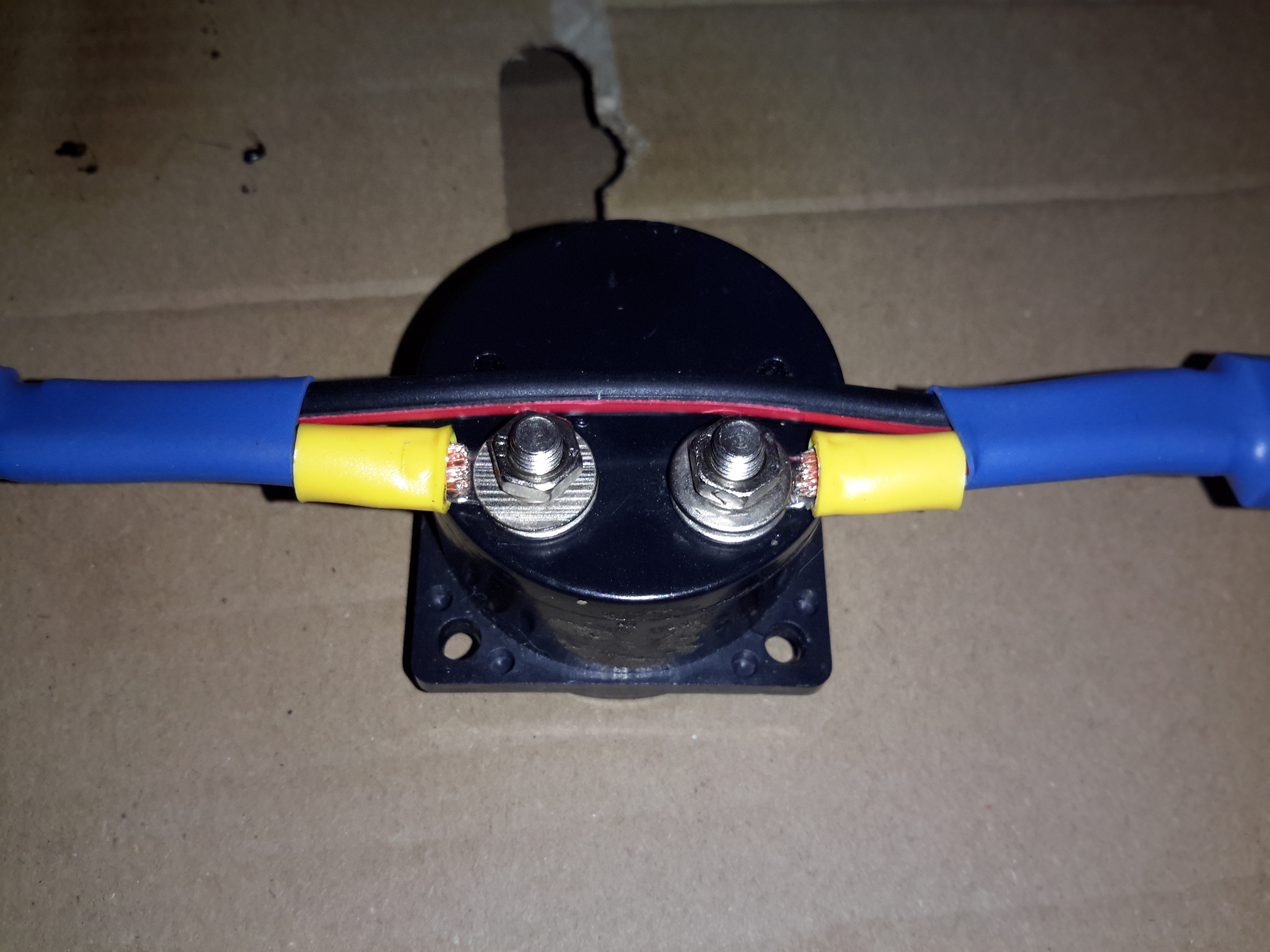
For the latest big project, replacing the battery bank on the boat with 5 brand new 200Ah Yuasa heavy duty flooded lead acids, I’m going to need to make many short links from heavy battery cable to connect all 5 batteries into a parallel bank.
Cutting cable as big in diameter as a good sized thumb is difficult at best. In the past I’ve used a hacksaw, but it doesn’t do a very clean job, especially as the cut nears the end – strands get ripped from the cable by the relatively coarse blade & this reduces the current carrying capacity.
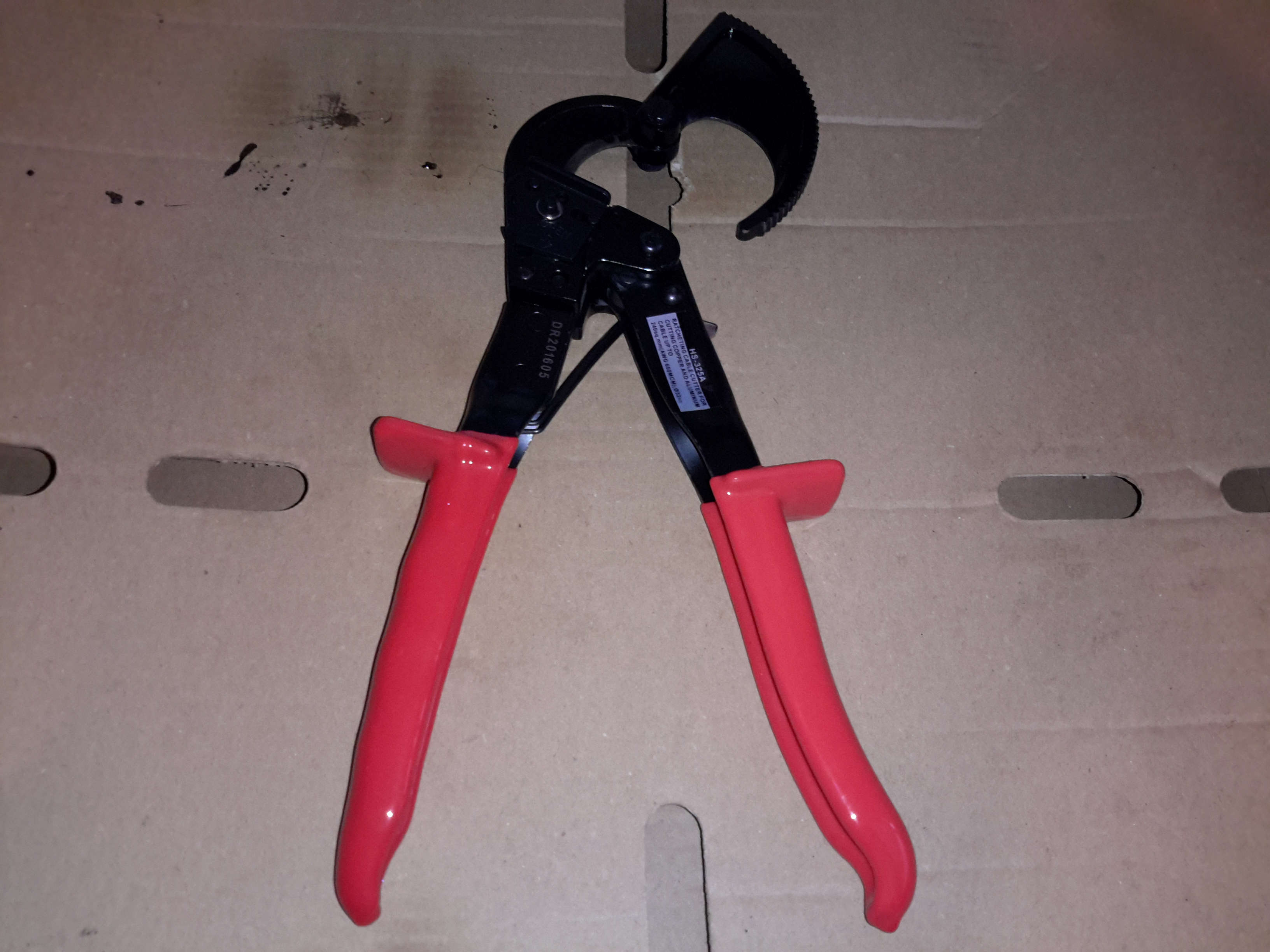
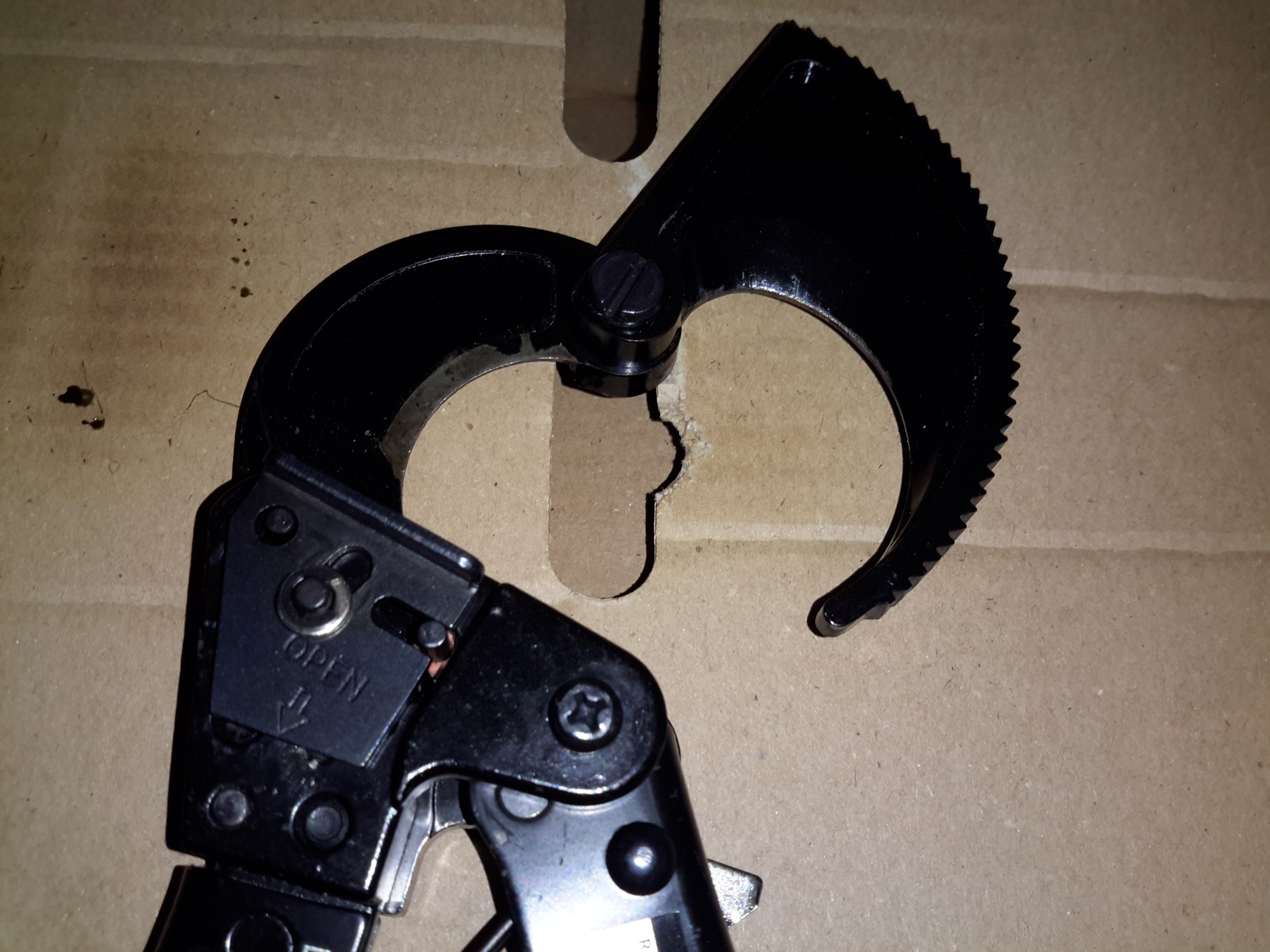
Over to eBay again netted a pair of ratchet-type heavy duty cable cutters for £30. These are rated to cut cable up to 240mm² or 600MCM.
Cutting Jaws
The cutting head on these snips is massive – cutting through cable up to 35mm in diameter takes some force. The ratchet mechanism is used to get a large mechanical advantage to force the cutters through the copper, without having to resort to more expensive & complex mechanisms such as hydraulics. (Hydraulic cable cutters do exist, but cost a small fortune & are totally over-rated for the job).
Overall the tool seems to be well made, the handles are Vinyl dipped to make them more comfortable, which certainly helps when applying a large amount of force. Running a file over the cutters themselves reveals they’re actually hardened – unusual for cheapo Chinese tools.
I recently decided to restock my toolkit, as there are plenty of jobs I need to sort that require the use of crimp terminals, so eBay again came to the rescue.
In my experience, cheap tools of any flavour are usually universally shite – I’ve had drill bits made out of a metal softer than aluminium, that unwind back into a straight flute bits as soon as they’re presented with anything harder to drill through than Cheese. Ditto for screwdrivers. But for once the far eastern factories seem to have done a reasonable job on this crimp tool set.
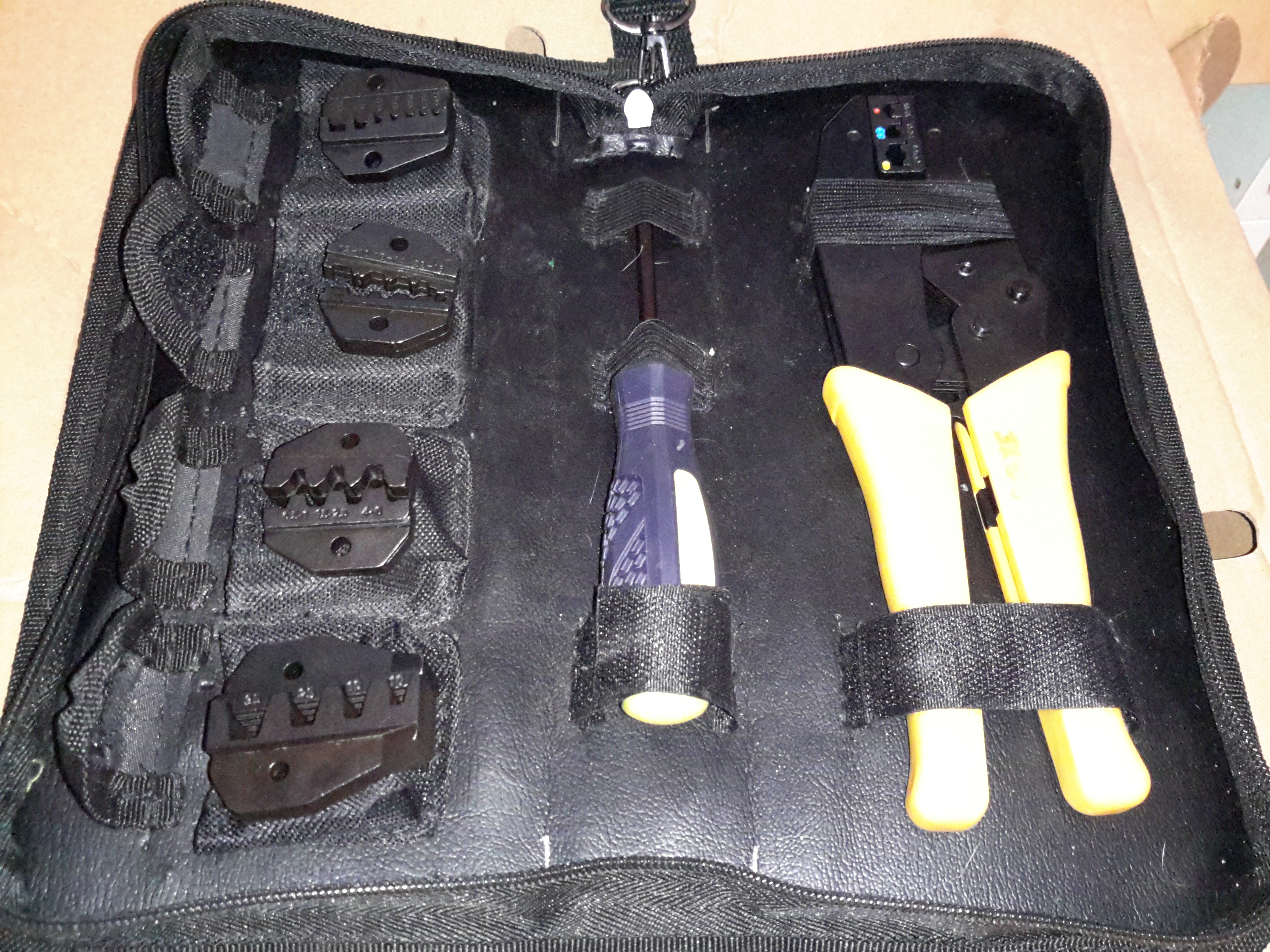
eBay Crimping Tools
These are ratchet type crimping pliers, with interchangable heads so many different types of terminals can be used. A handy Philips screwdriver is included in the kit for changing the dies.
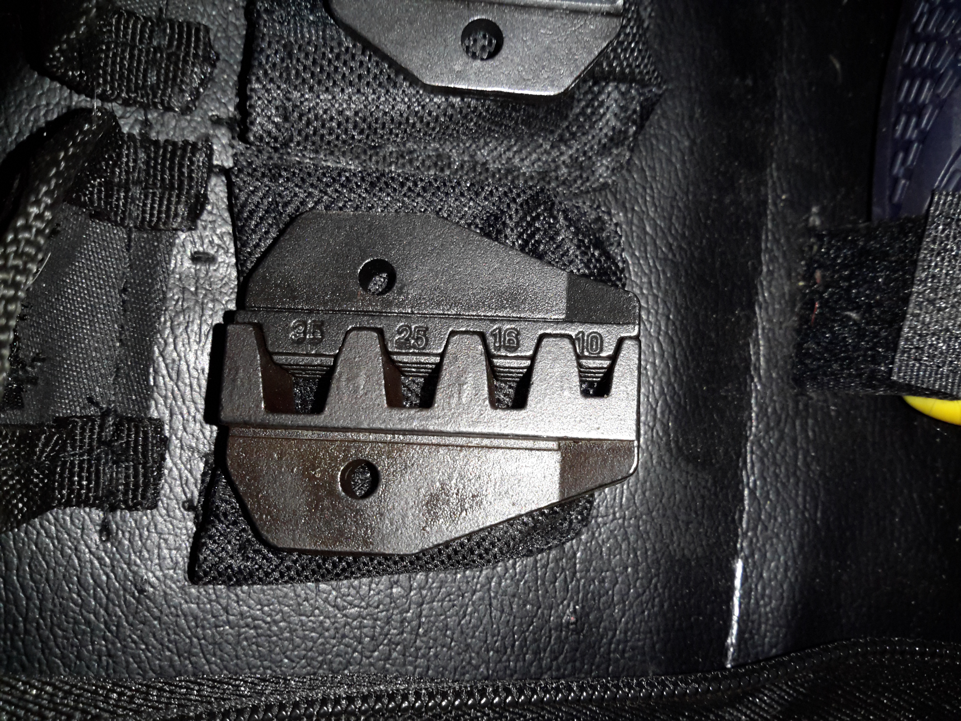
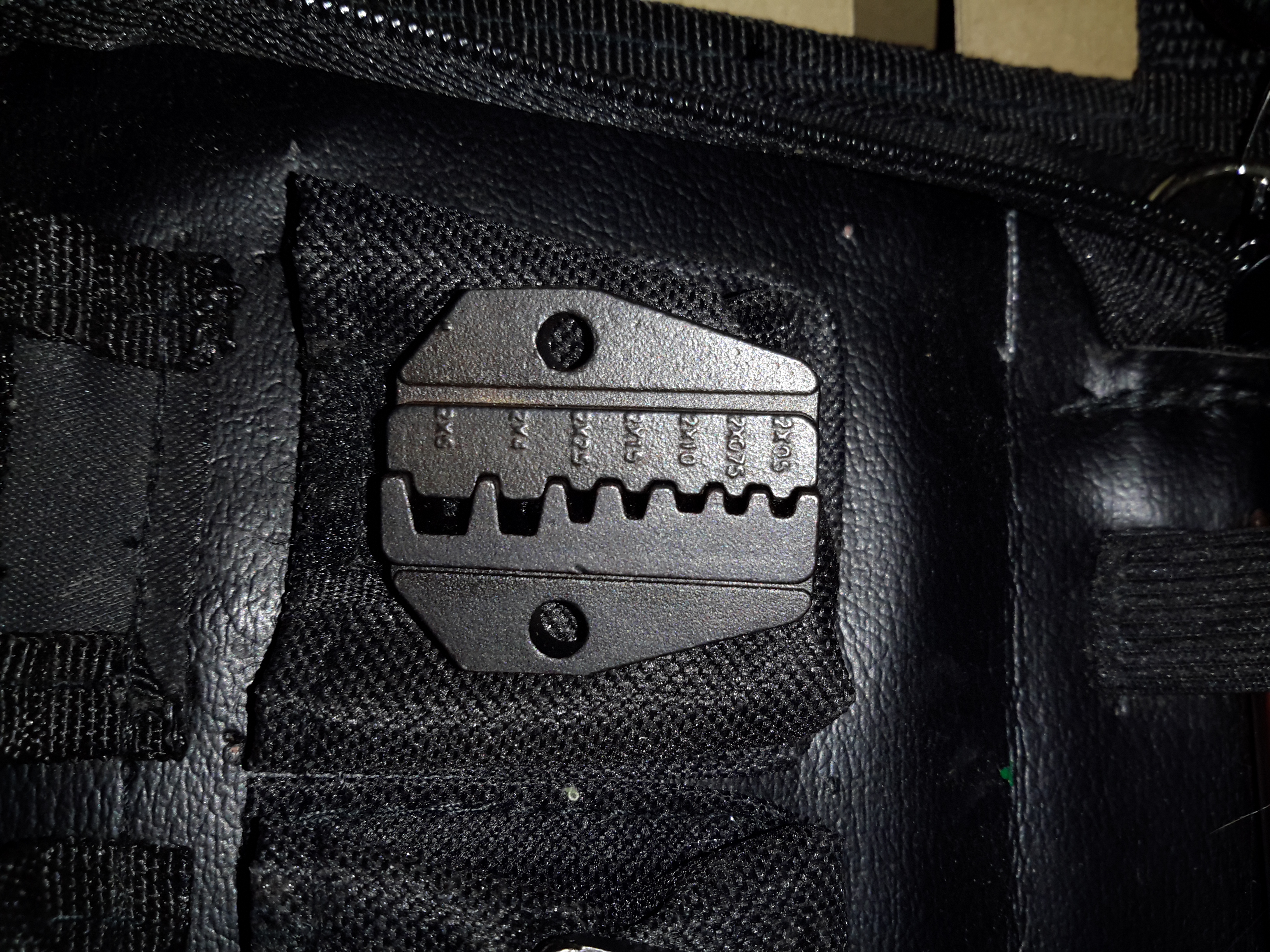
Large Dies
The largest dies in the set can handle cable up to 25mm² – just about the bottom end of main battery cables, which is very handy.
Medium Dies
Smaller sets of dies are provided for other types of terminals.
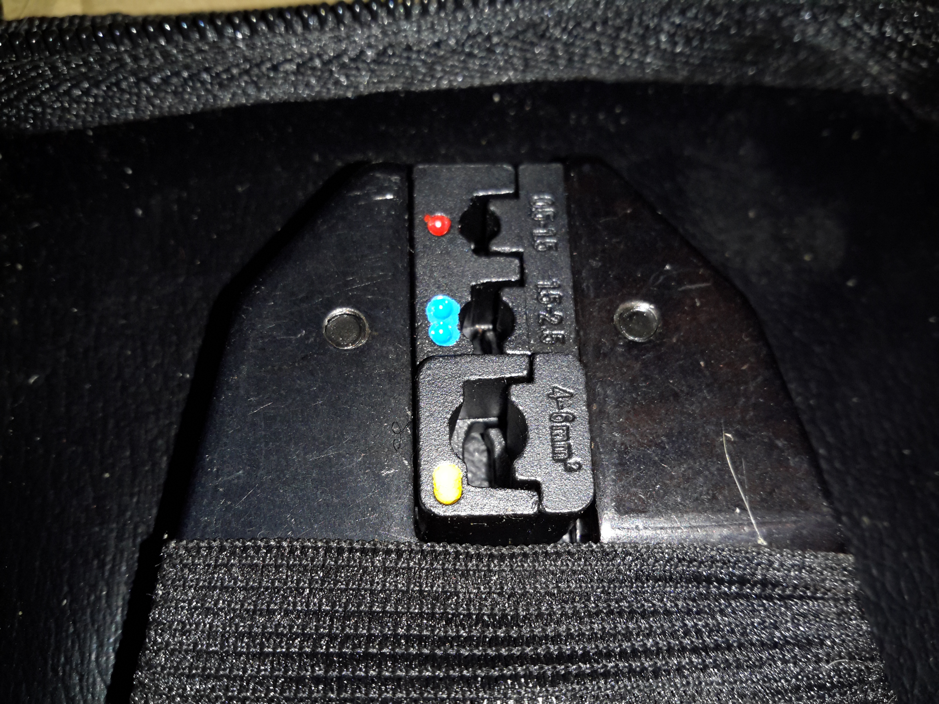
Small Dies
I’m not precisely sure which type of terminals these dies fit – the profile is a bit unusual.
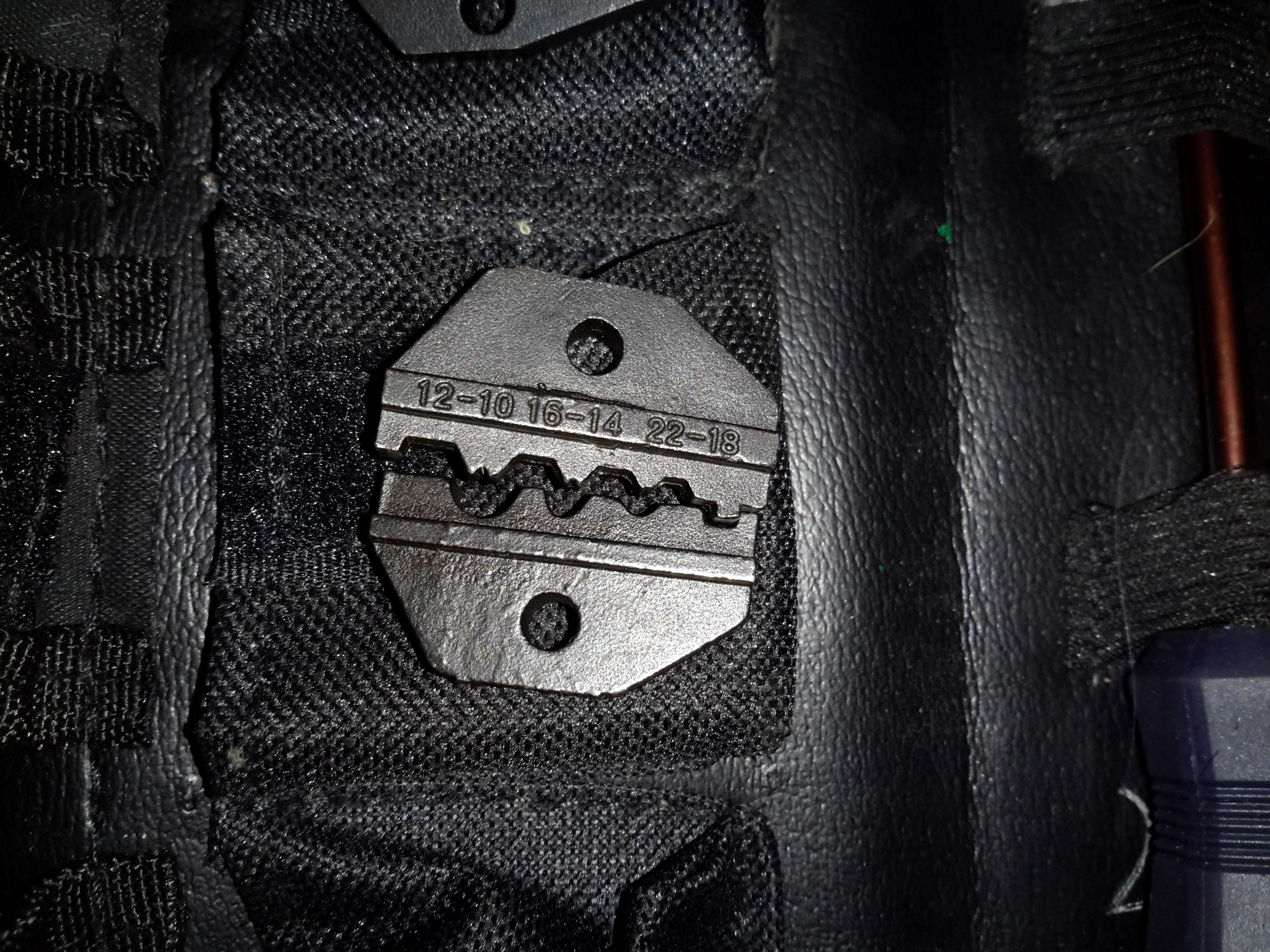
Tiny Dies
The smallest dies in the set are good for extremely small wires – down to 0.5mm
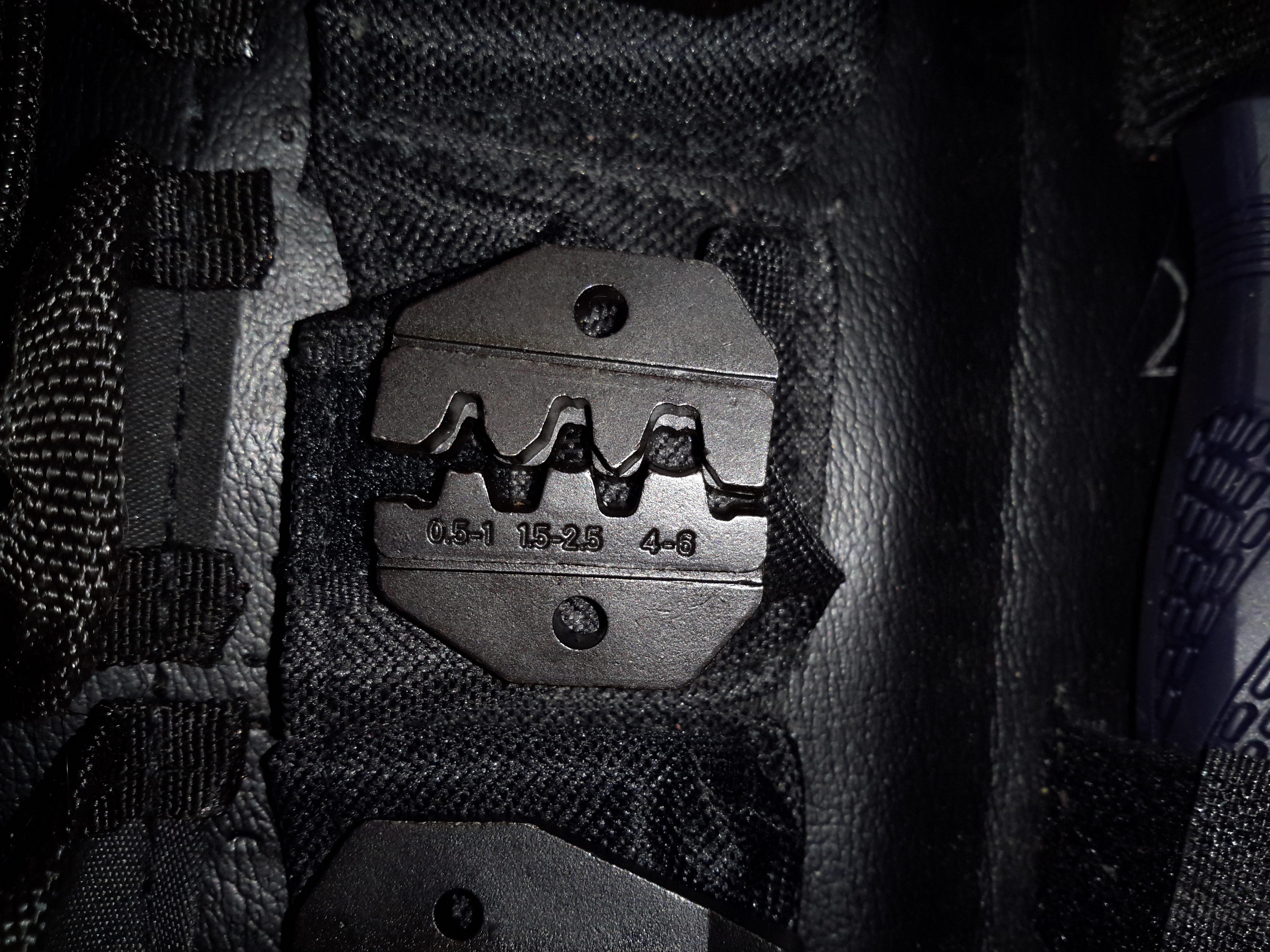
Automotive Dies
The pliers are supplied with the standard colour-coded automotive dies installed. Sometimes these terminals never crimp properly, as the dies just effectively crush the copper tube of the terminal, so more often than not the wire strands are just forced out of the terminal as the crimp is made, leaving a bad connection.
These are even better than the ratchet-type crimp tools at the local Maplin Electronics – the set of those I have just distorts when a large crimp is made, so the terminal never gets a full crimp. The steel is not stiff enough to handle the forces required.
Example Crimp
Here’s a couple of large crimps on 6mm² cable attached to an ammeter. The crimps are nice & tight & hold onto the cable securely. The insulating sleeve on the terminals also hasn’t been cut through by the dies, which is often a problem on cheap crimp tools.
Going through eBay recently looking for parts for a couple of CRT-based projects, I came across these DC-DC converters.
Apparently rated from 45-390v DC output at 200mA, these should be ideal for driving some of the electrodes (focus, screen, grid) in a CRT.
Above is the top of the board, input voltage header on the left, output voltage adjust in the centre & output voltage header on the right.
This module has a mini-automotive fuse, at 10A for input protection.
On the heatsink is mounted the main switching MOSFET, a RU7088R from Ruichips. This FET is fairly heavily rated at 70v 80A, with 6.5mΩ on-resistance.
PCB Bottom
The bottom of the board has the control components, with a pair of ICs. Unfortunately the numbers have been scrubbed off, so no identification here. The output from the transformer is rectified with a single large SMD diode on the left side of the board.
There’s also plenty of isolation gap between the HV output trace & the low voltage logic side of the circuit, the two being bridged only by a resistive divider for output voltage measurement.
For my latest project, I needed an easier way to paint without messing about with brushes, and the associated marks they leave in a paint job. eBay provided me with a cheap airbrush & compressor.
Airbrush Kit
For less than £30, this kit doens’t look so bad. I’ve never used an airbrush before, but I’ve had no problems with this as yet spraying both water based paints & solvent based paints.
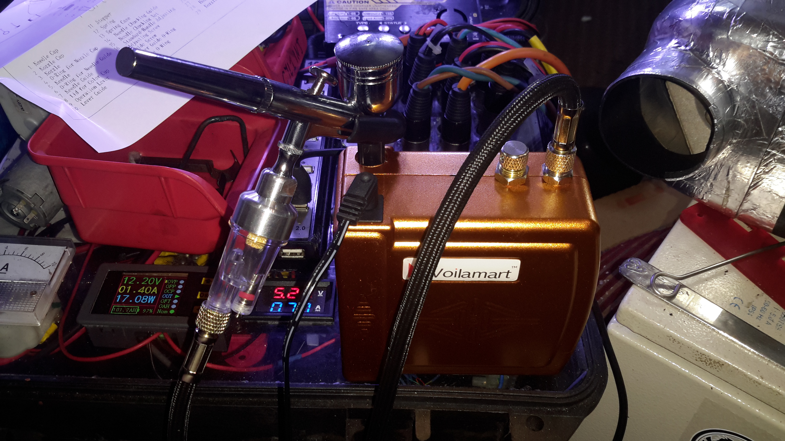
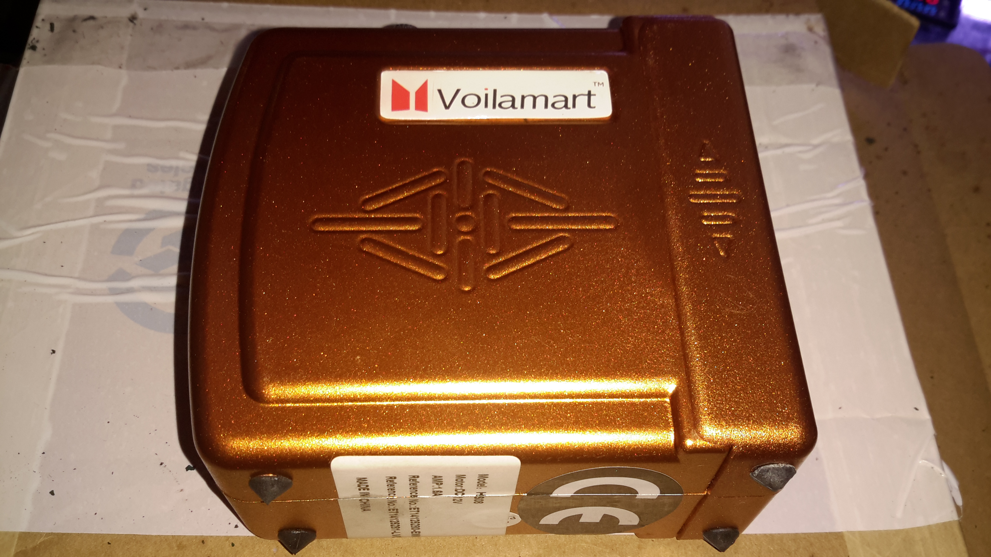
Compressor
Here’s the compressor itself, this runs on 12v & has an output pressure of 1.5 Bar, which is supposed to be adjustable.
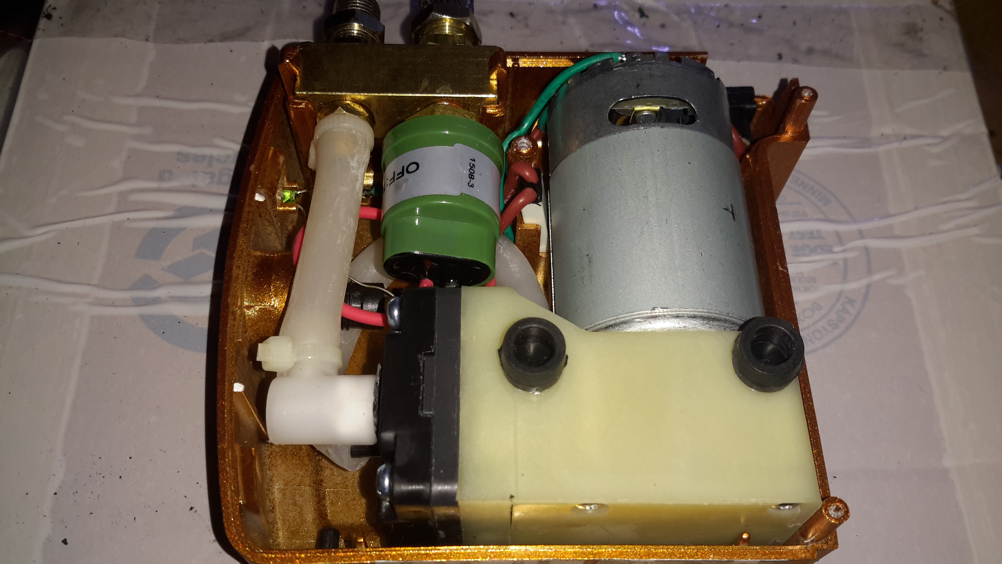
Compressor Internals
Removing a couple of screws reveals the internal components. Nothing much unusual here, a DC diaphragm pump, pressure switch & outlet fittings. There’s also a thermal cutout fitted next to the motor for protection.
The pressure switch attached to the manifold trips at 1.5Bar, keeping the pressure to the brush pretty much constant.
Air Block
Next to the air outlet fitting is an adjustment knob, supposedly for varying the pressure. However it’s just a piss-poorly designed adjustable relief valve that vents to atmosphere. There’s not much of a control range.
Messy Wiring
The wiring gets a bit messy where the power LED is concerned, with no heatshrink over the solder joints, but it’s adequate.
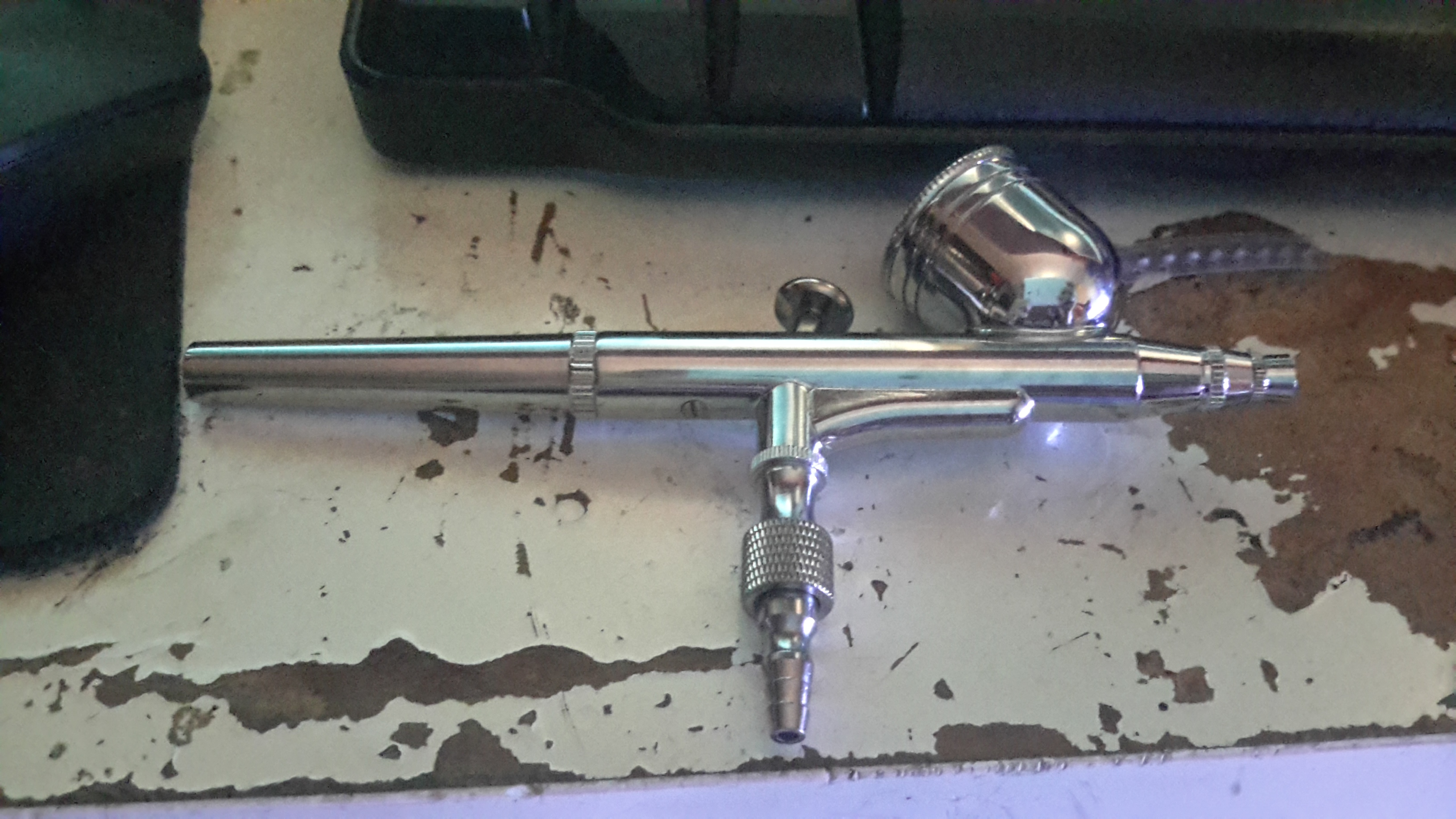
Airbrush
The airbrush itself isn’t too bad. It’s solid Brass, with a very nice Chrome finish. I’m not expecting miracles from a very cheap tool, but it certainly seems to be reasonable.
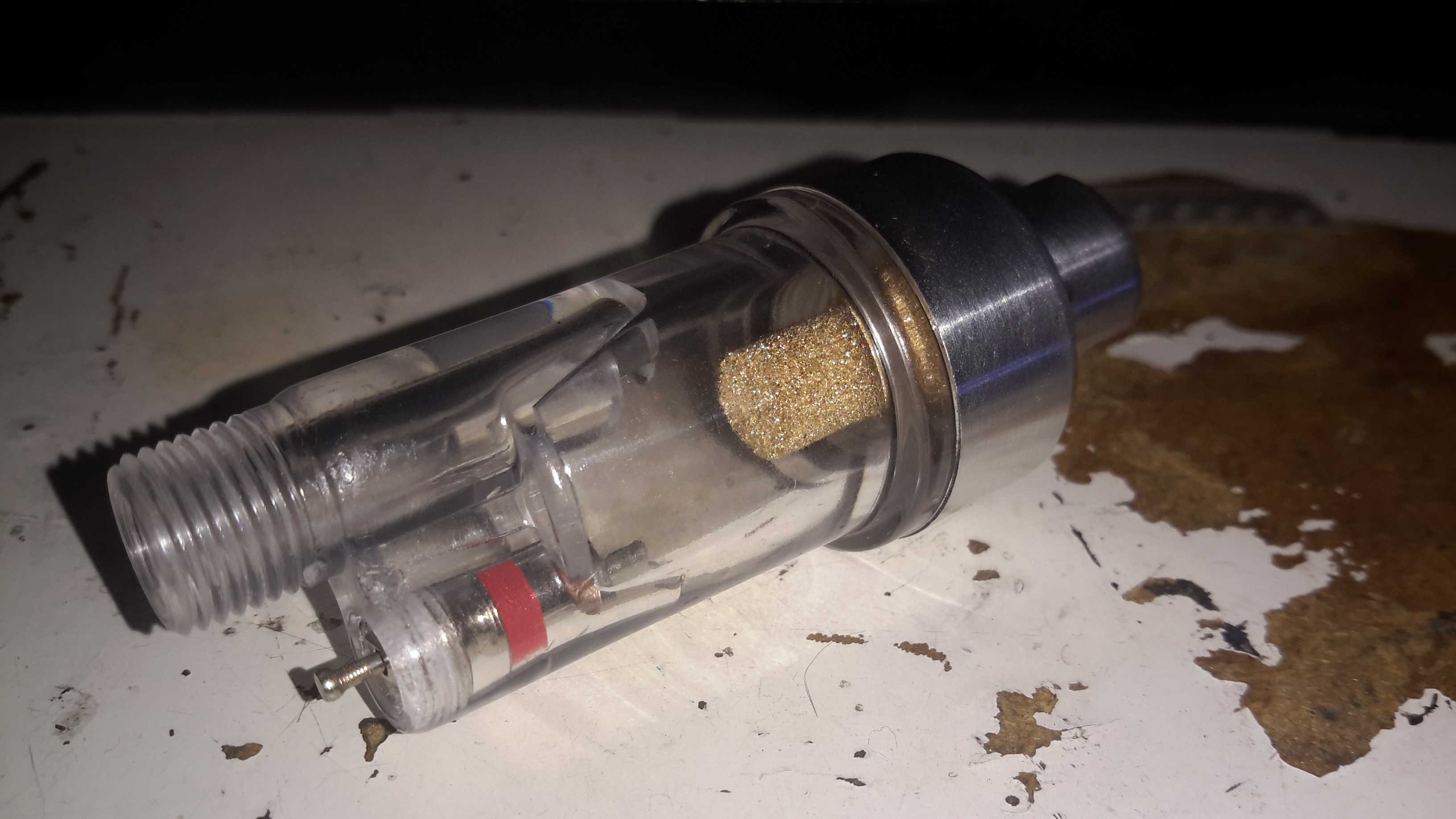
Water Trap
A moisture trap is supplied for the brush, to prevent water drops being sprayed out with the paint. Very handy.
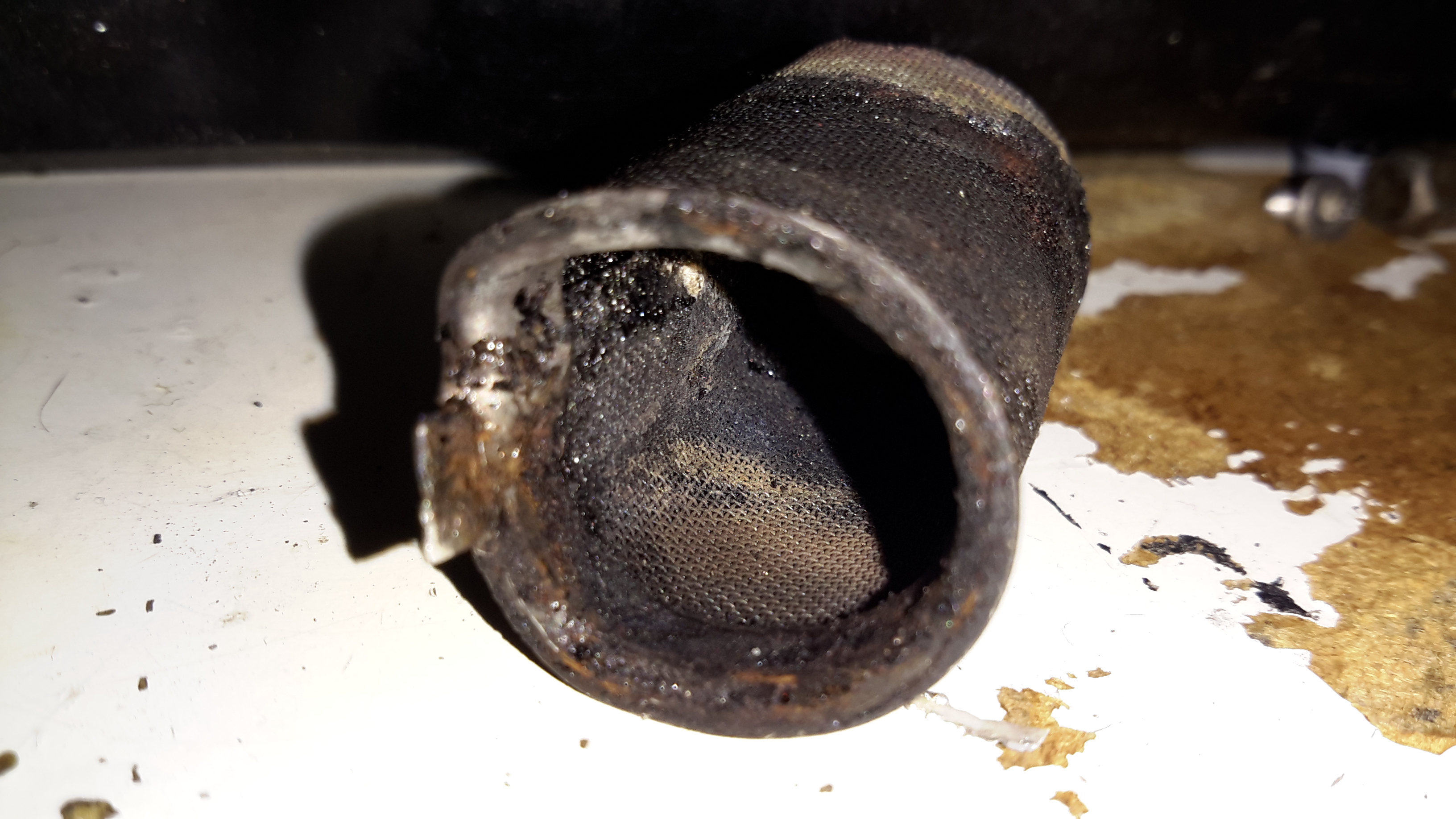
A while ago I posted about the glowplug screens in Eberspacher heaters, and making some DIY ones, as the OEM parts are hideously expensive for a piece of stainless mesh (£13).
Old Screen
Above is the old factory screen that I extracted after only 5 gallons of diesel was run through it, it’s heavily clogged up with carbon & tar. The result of this clogging is a rather slow & smoky start of the heater & surging of the burner while at full power.
It wasn’t as badly stuck in the chamber as some I’ve removed, but extracting it still caused the steel ring to deform, this was after using a scalpel blade to scrape the carbon off the rim.
At the time I did some tests with some spare copper mesh I had to hand, but the problem with copper is that it’s very soft & malleable, so didn’t really hold it’s shape well enough. The factory screens are spot welded to keep them in shape, but as I don’t have a spot welder, I am relying on the mesh having a bit of springiness to keep it in place against the walls of the glowplug chamber.
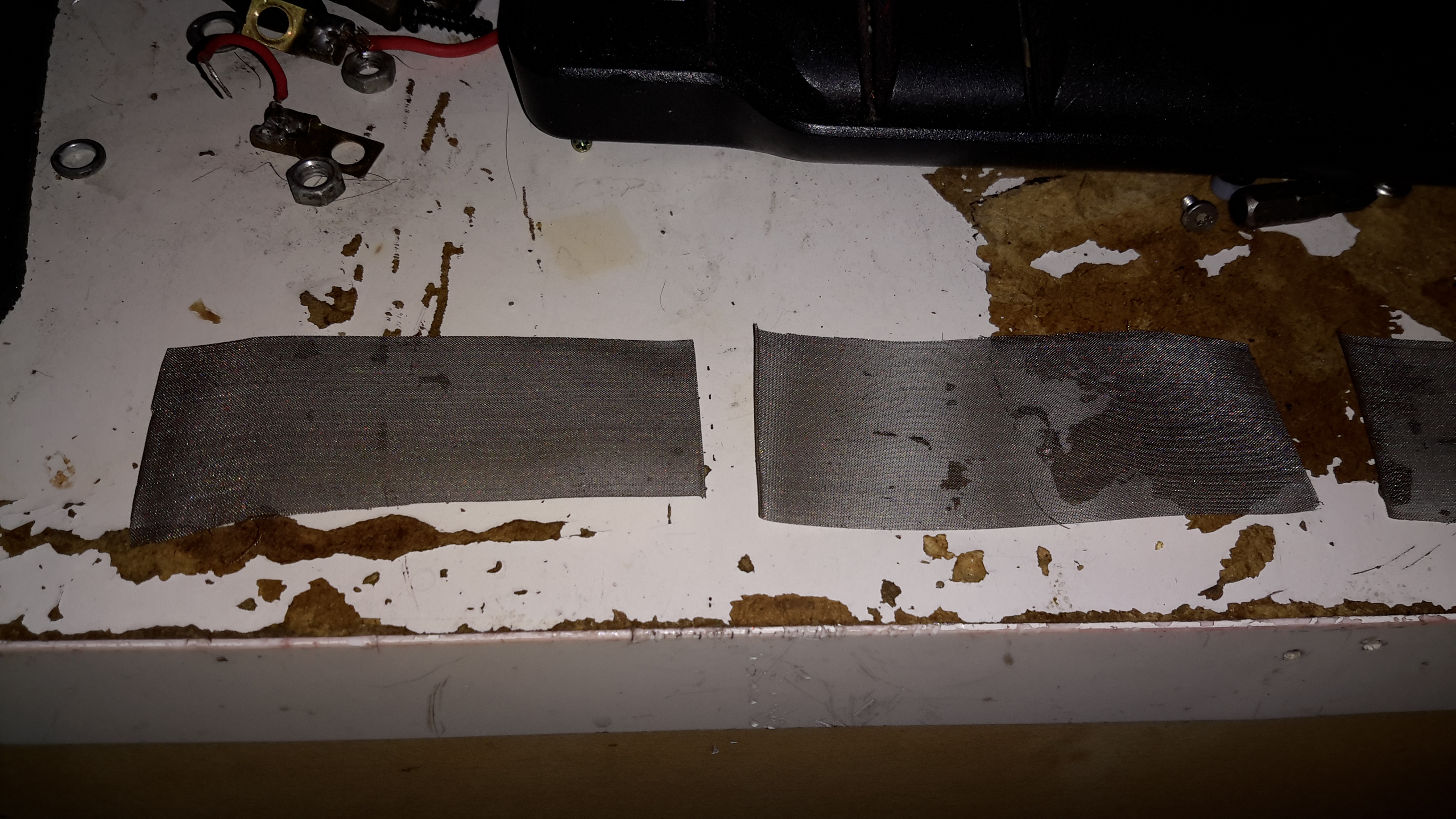
eBay provided a piece of 120 mesh stainless steel mesh, 300mmx300mm for £8. It’s a bit finer than the stock stuff, but appears to work perfectly fine as long as there’s no gunk in the fuel to clog it up.
I cut a strip off the large piece, as wide as the OEM screen, about 32mm. This 300mm long strip is then cut into 4 pieces, each 75mm long. (it’s easily cut with scissors, but mind the stray wires on the edges! They’re very sharp & penetrate skin easily!).
Mesh Screen
These pieces are just the right size to form a complete loop in the glowplug chamber, and the stainless is springy enough so that it doesn’t deform & become loose.
The OEM screen is multiple turns of a more coarse mesh, but the finer mesh size of the screens I’m using means only one turn is required. Multiple turns would probably be too restrictive to fuel flow.
With one of these pieces of mesh in place, the heater starts instantly, without even a wisp of smoke from the exhaust. Burner surging is also eliminated. Even if the service life of my DIY replacement isn’t as long as an OEM screen, the low price for such a large number of replacements certainly offsets that disadvantage!
A piece of mesh from eBay would provide enough material for quite a lot of replacements, and probably more than the service life of the burner itself!
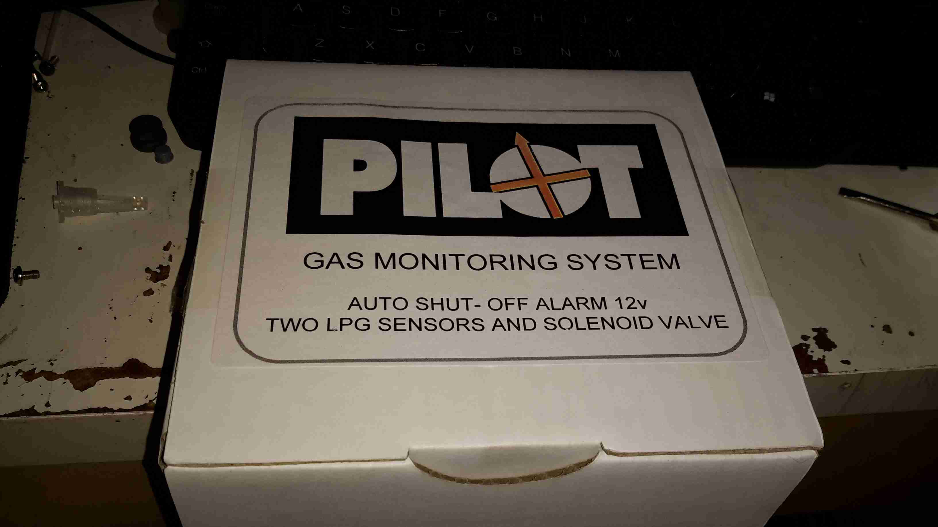
In my mind, the most dangerous thing onboard any boat is the LPG system, as the gas is heavier than air, any leaks tend to collect in the bilges, just waiting for an ignition source. To mitigate this possibility, we’re fitting a gas monitoring system that will sound an alarm & cut off the supply in case of a leak.
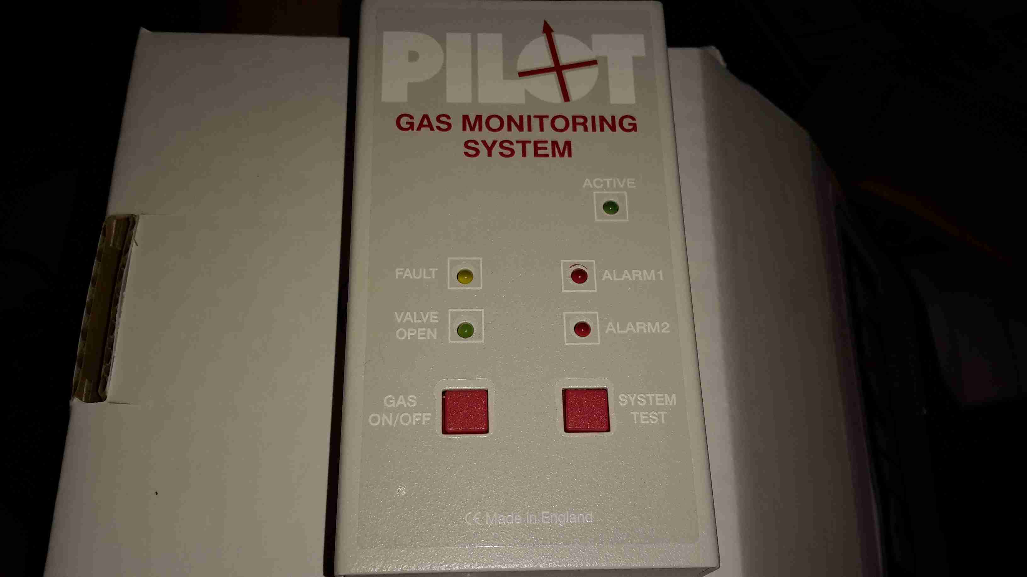
Monitor Unit
Here’s the monitor itself, the two sensor model. It’s nice & compact, and the alarm is loud enough to wake the dead.
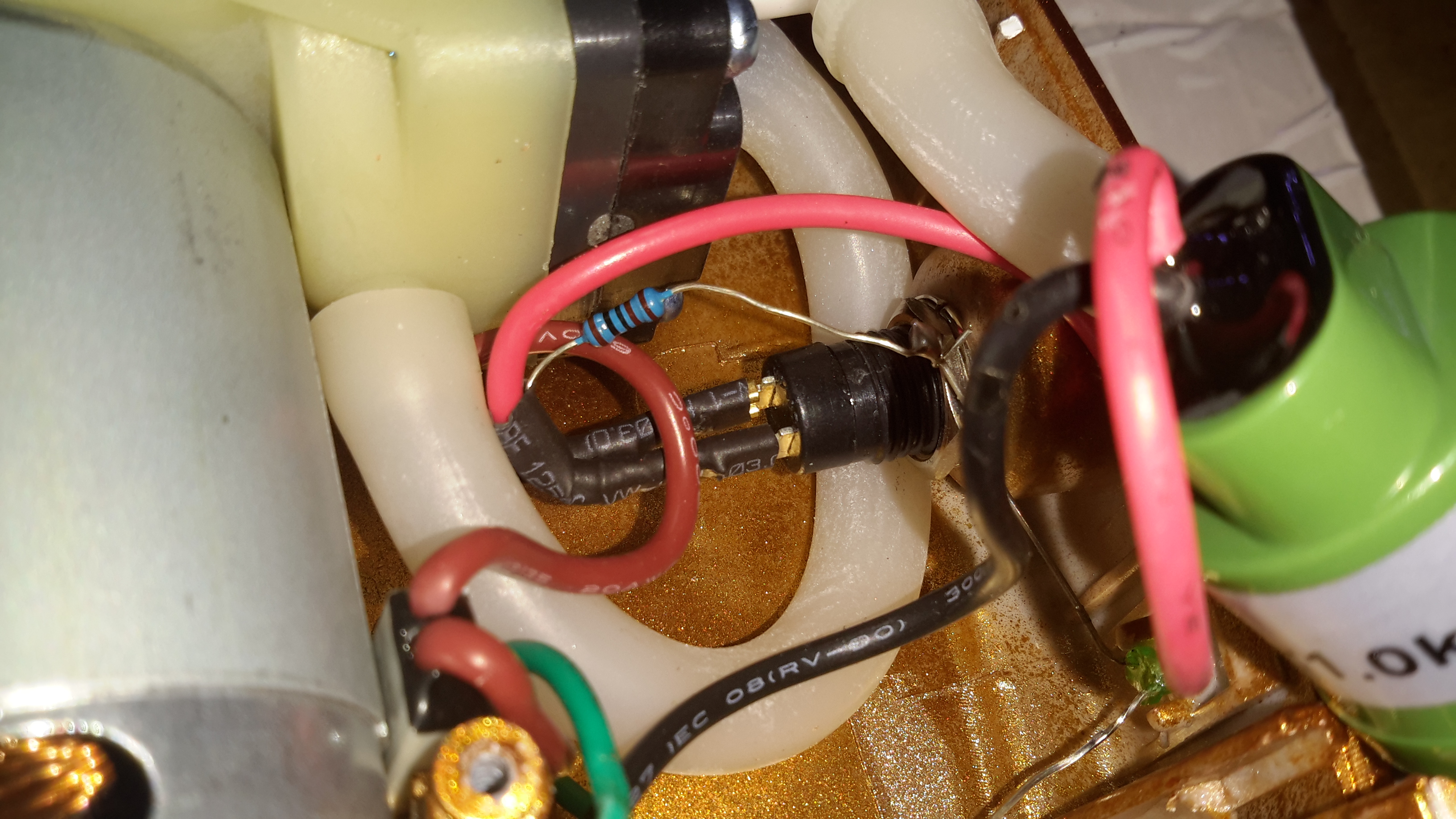
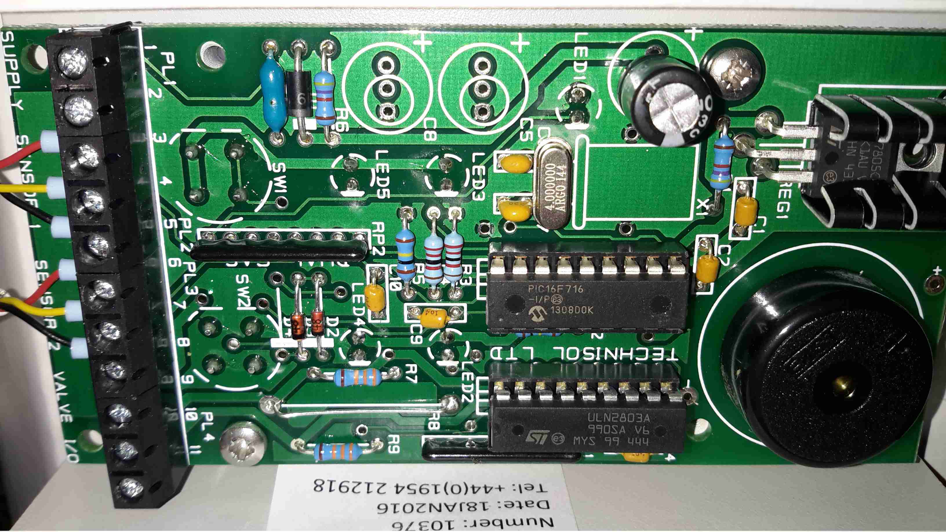
Control Board
Not much inside in the way of circuitry, the brains of the operation is a Microchip PIC16F716 8-bit microcontroller with an onboard A/D converter (needed to interface with the sensors), running at 4MHz. The solenoid valve is driven with a ULN2803 Darlington transistor array.
The alarm Piezo sounder can be seen to the right of the ICs, above that is a simple LM7805 linear regulator providing power to the electronics.
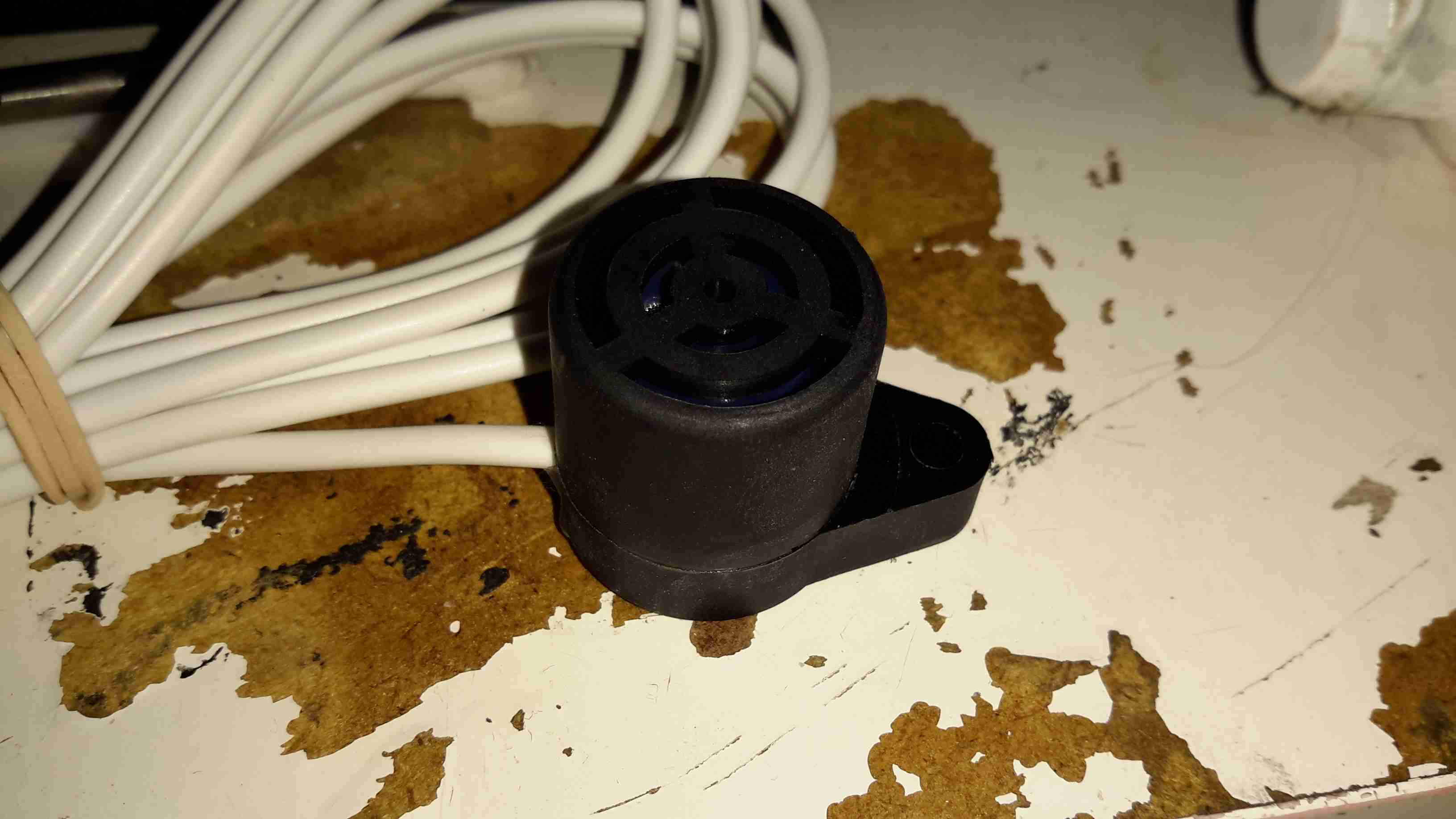
Remote Sensor
The pair of remote sensors come with 3.5m of cable, a good thing since the mounting points for these are going to be rather far from the main unit in our installation.
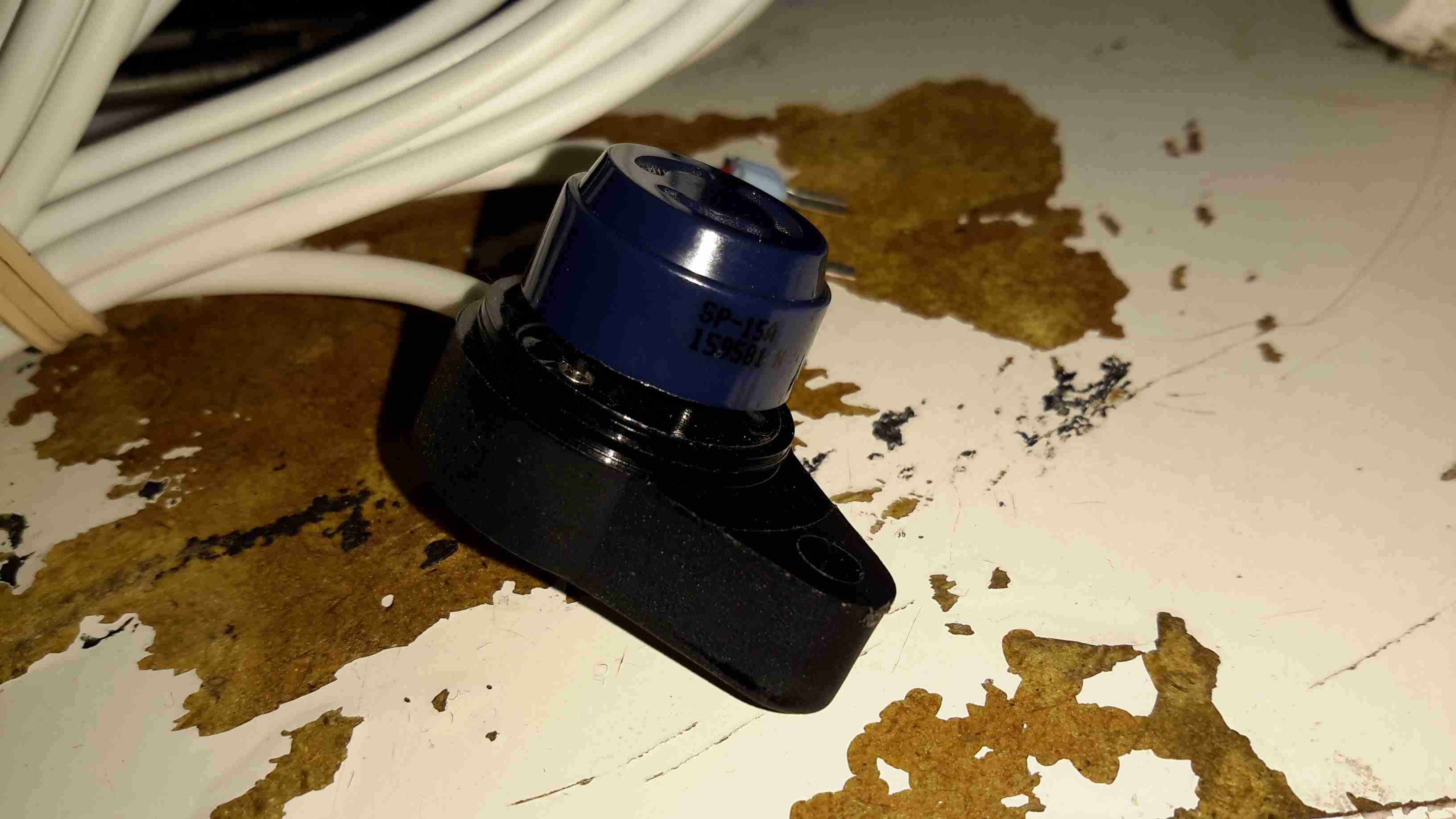
Sensor Element
The sensor itself is a SP-15A Tin Oxide semiconductor type, most sensitive to butane & propane. Unlike the Chinese El-Cheapo versions on eBay, these are high quality sensors. After whiffing some gas from a lighter at one of the sensors, the alarm triggered instantly & tripped the solenoid off.
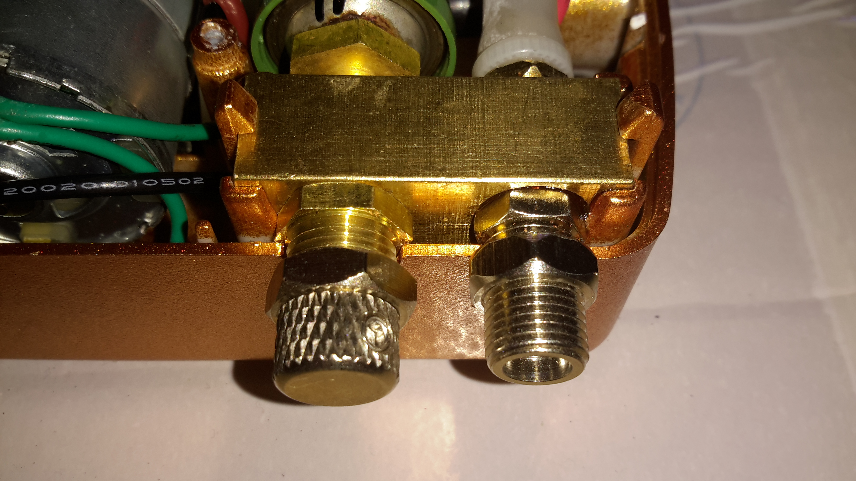
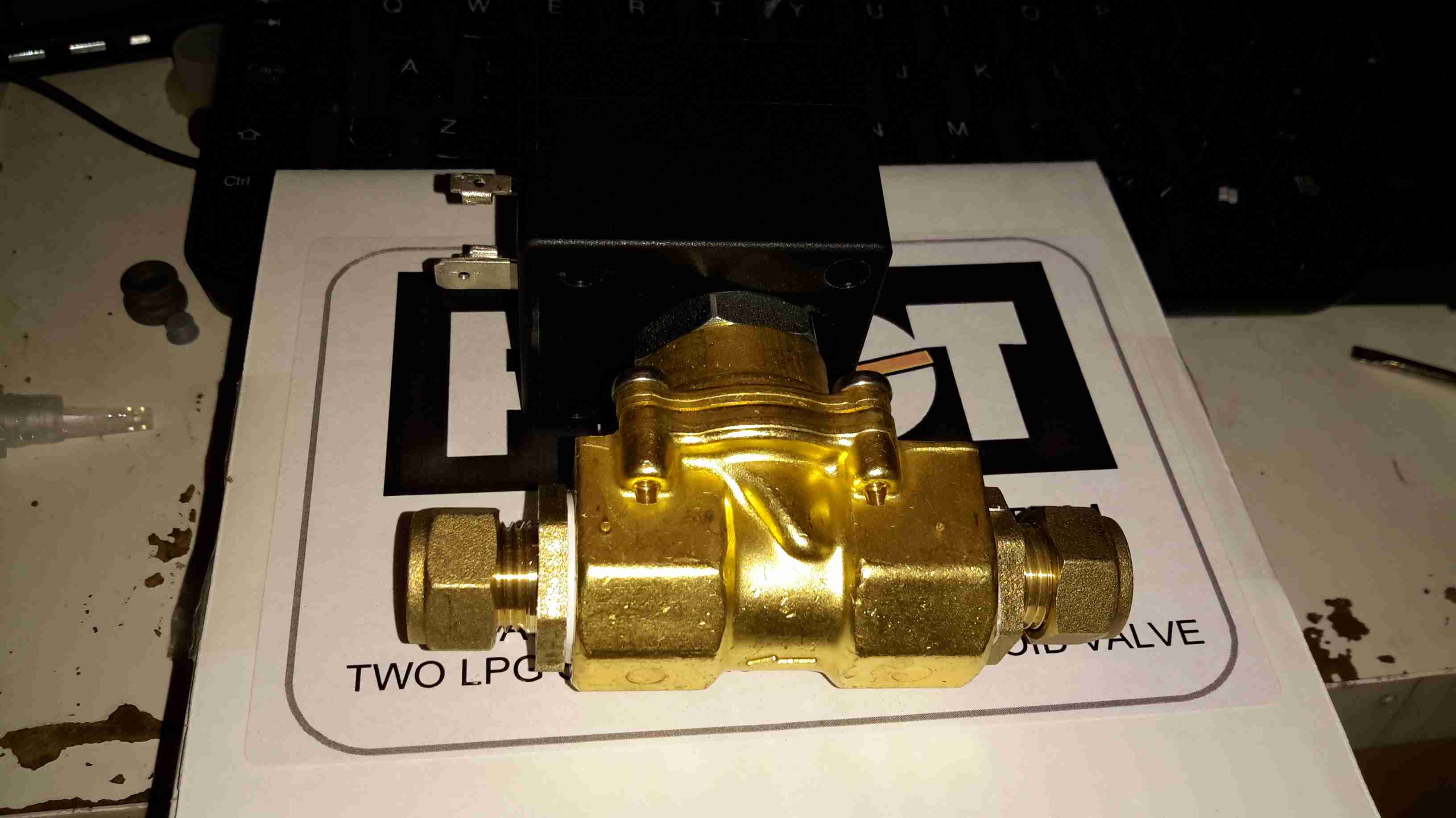
Solenoid Valve
The solenoid valve goes into the gas supply line after the bottle regulator, in this case I’ve already fitted the adaptors to take the 10mm gas line to the 1/2″ BSP threads on the valve itself. This brass lump is a bit heavy, so support will be needed to prevent vibration compromising the gas line.
As I’ve been posting some photos of decapped ICs lately, I thought I’d share the process I use personally for those that might want to give it a go 😉
The usual method for removing the epoxy package from the silicon is to use hot, concentrated Nitric Acid. Besides the obvious risks of having hot acids around, the decomposition products of the acid, namely NO² (Nitrogen Dioxide) & NO (Nitrogen Oxide), are toxic and corrosive. So until I can get the required fume hood together to make sure I’m not going to corrode the place away, I’ll leave this process to proper labs ;).
The method I use is heat based, using a Propane torch to destroy the epoxy package, without damaging the Silicon die too much.
TMS57002 Audio DSP
I start off, obviously, with a desoldered IC, the one above an old audio DSP from TI. I usually desolder en-masse for this with a heat gun, stripping the entire board in one go.
FLAMES!
Next is to apply the torch to the IC. A bit of practice is required here to get the heat level & time exactly right, overheating will cause the die to oxidize & blacken or residual epoxy to stick to the surface.
I usually apply the torch until the package just about stops emitting it’s own yellow flames, meaning the epoxy is almost completely burned away. I also keep the torch flame away from the centre of the IC, where the die is located.
Breathing the fumes from this process isn’t recommended, no doubt besides the obvious soot, the burning plastic will be emitting many compounds not brilliant for Human health!
Once the IC is roasted to taste, it’s quenched in cold water for a few seconds. Sometimes this causes such a high thermal shock that the leadframe cracks off the epoxy around the die perfectly.
All Your Die Belong To Us
Now that the epoxy has been destroyed, it breaks apart easily, and is picked away until I uncover the die itself. (It’s the silver bit in the middle of the left half). The heat from the torch usually destroys the Silver epoxy holding the die to the leadframe, and can be removed easily from the remaining package.
Decapped
BGA packages are usually the easiest to decap, flip-chip packages are a total pain due to the solder balls being on the front side of the die, I haven’t managed to get a good result here yet, I’ll probably need to chemically remove the first layer of the die to get at the interesting bits 😉
Slide
Once the die has been rinsed in clean water & inspected, it’s mounted on a glass microscope slide with a small spot of Cyanoacrylate glue to make handling easier.
Some dies require some cleaning after decapping, for this I use 99% Isopropanol & 99% Acetone, on the end of a cotton bud. Any residual epoxy flakes or oxide stuck to the die can be relatively easily removed with a fingernail – turns out fingernails are hard enough to remove the contamination, but not hard enough to damage the die features.
Once cleaning is complete, the slide is marked with the die identification, and the photographing can begin.
Microscope Mods
I had bought a cheap eBay USB microscope to get started, as I can’t currently afford a proper metallurgical microscope, but I found the resolution of 640×480 very poor. Some modification was required!
Modified Microscope
I’ve removed the original sensor board from the back of the optics assembly & attached a Raspberry Pi camera board. The ring that held the original sensor board has been cut down to a minimum, as the Pi camera PCB is slightly too big to fit inside.
The stock ring of LEDs is run direct from the 3.3v power rail on the camera, through a 4.7Ω resistor, for ~80mA. I also added a 1000µF capacitor across the 3.3v supply to compensate a bit for the long cable – when a frame is captured the power draw of the camera increases & causes a bit of voltage drop.
The stock lens was removed from the Pi camera module by careful use of a razor blade – being too rough here *WILL* damage the sensor die or the gold bond wires, which are very close to the edge of the lens housing, so be gentle!
Mounting Base
The existing mount for the microscope is pretty poor, so I’ve used a couple of surplus ceramic ring magnets as a better base, this also gives me the option of raising or lowering the base by adding or removing magnets.
To get more length between the Pi & the camera, I bought a 1-meter cable extension kit from Pi-Cables over at eBay, cables this long *definitely* require shielding in my space, which is a pretty aggressive RF environment, or interference appears on the display. Not surprising considering the high data rates the cable carries.
The FFC interface is hot-glued to the back of the microscope mount for stability, for handheld use the FFC is pretty flexible & doesn’t apply any force to the scope.
Die Photography
Since I modified the scope with a Raspberry Pi camera module, everything is done through the Pi itself, and the raspistill command.
Pi LCD
The command I’m currently using to capture the images is:
raspistill -ex auto -awb auto -mm matrix -br 62 -q 100 -vf -hf -f -t 0 -k -v -o CHIPNAME_%03d.jpg
This command waits between each frame for the ENTER key to be pressed, allowing me to position the scope between shots. Pi control & file transfer is done via SSH, while I use the 7″ touch LCD as a viewfinder.
The direct overhead illumination provided by the stock ring of LEDs isn’t ideal for some die shots, so I’m planning on fitting some off-centre LEDs to improve the resulting images.
Image Processing
Obviously I can’t get an ultra-high resolution image with a single shot, due to the focal length, so I have to take many shots (30-180 per die), and stitch them together into a single image.
For this I use Hugin, an open-source panorama photo stitching package.
Hugin
Here’s Hugin with the photos loaded in from the Raspberry Pi. To start with I use Hugin’s built in CPFind to process the images for control points. The trick with getting good control points is making sure the images have a high level of overlap, between 50-80%, this way the software doesn’t get confused & stick the images together incorrectly.
Optimiser
After the control points are generated, which for a large number of high resolution images can take some time, I run the optimiser with only Yaw & Pitch selected for all images.
Optimising
If all goes well, the resulting optimisation will get the distance between control points to less than 0.3 pixels.
Panorama Preview
After the control points & optimisation is done, the resulting image can be previewed before generation.
Texas Instruments TMS67002
After all the image processing, the resulting die image should look something like the above, with no noticeable gaps.
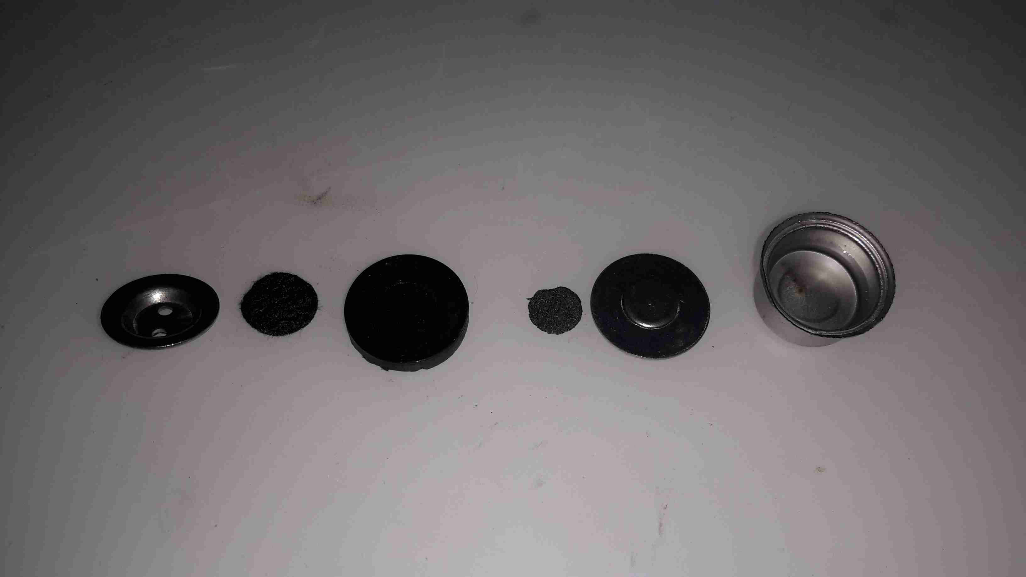
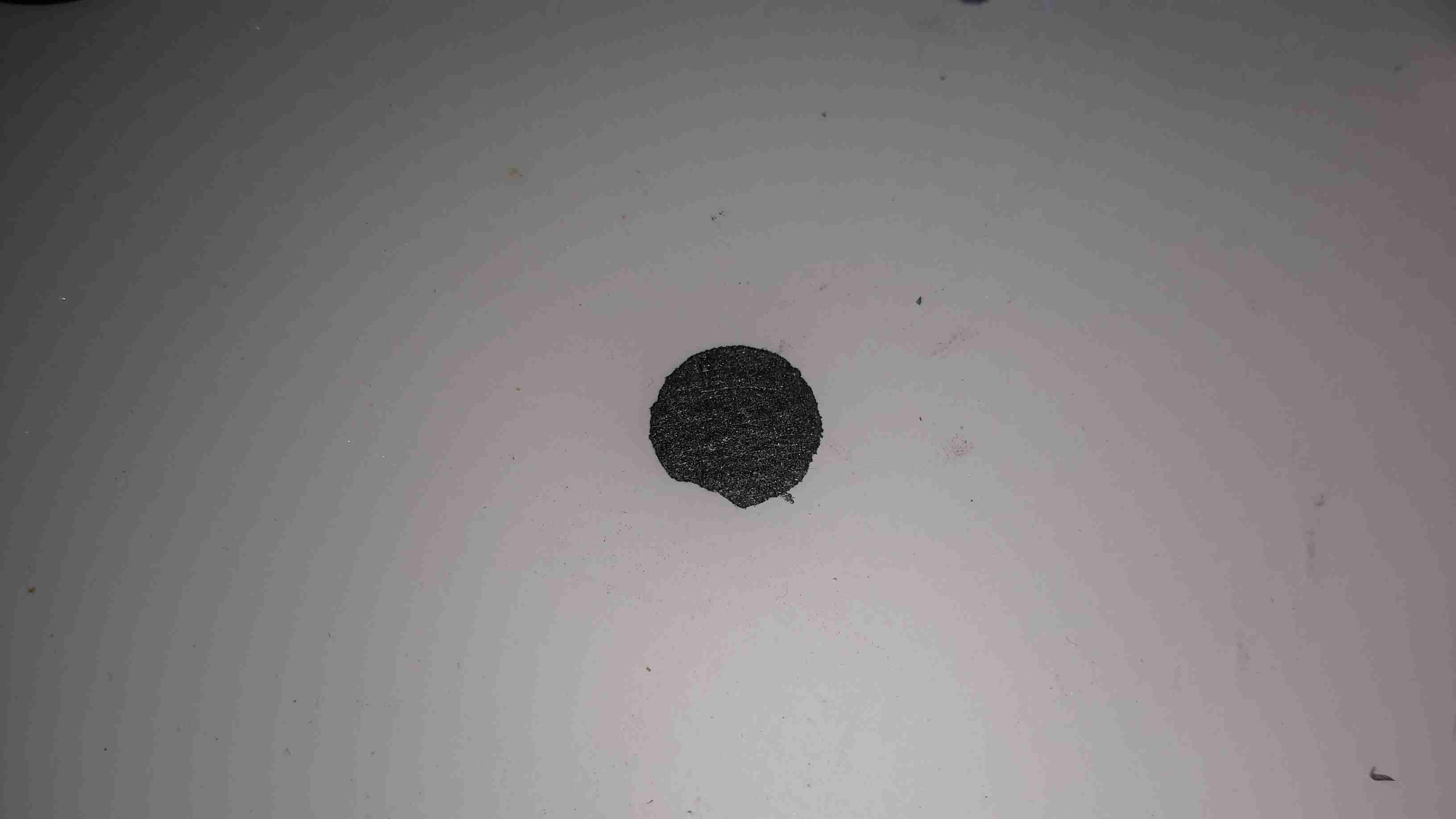
As the CO meter I bought on eBay didn’t register anything whatsoever, I decided I’d hack the sensor itself apart to make sure it wasn’t just an empty steel can. It turns out that it’s not just an empty can, but there are some reasons why the thing doesn’t work 😉
Cell Disassembled
The cell was crimped together under the yellow shrinkwrap, but that’s nothing my aviation snips couldn’t take care of. The photo above shows the components from inside.
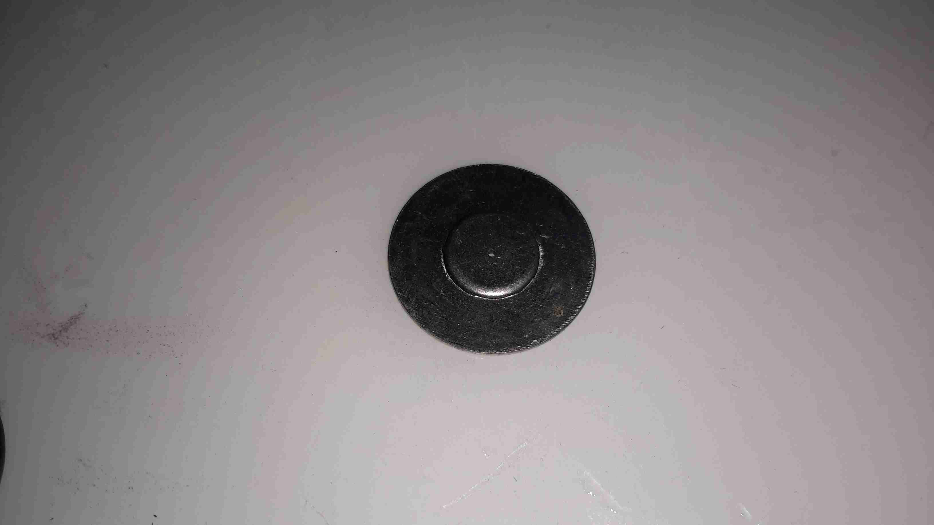
End Cap
The endcap is just a steel pressing, nothing special here.
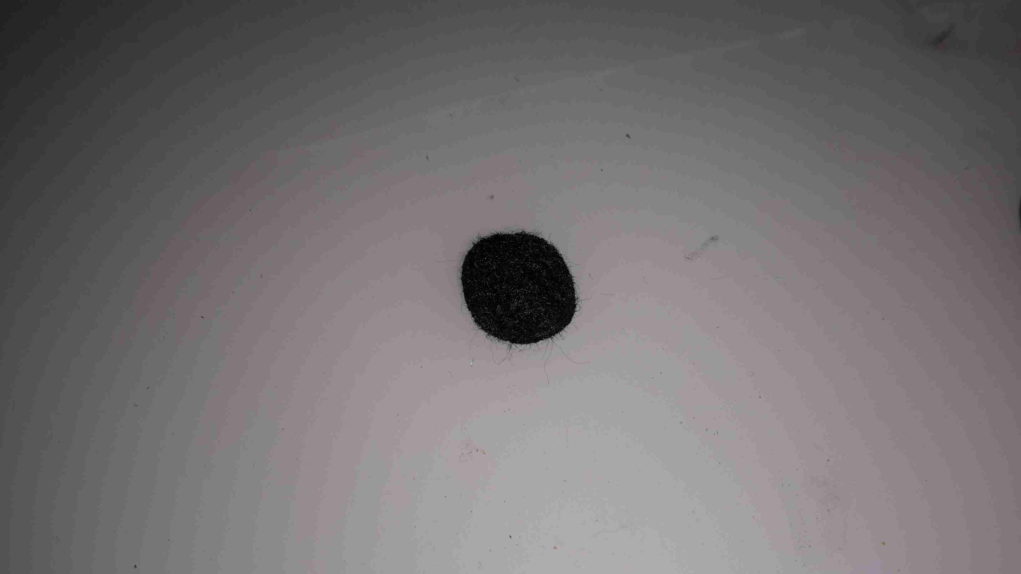
Filter
Also pretty standard is the inlet filter over the tiny hole in the next plate, even though it’s a lot more porous that I’ve seen before in other sensors.
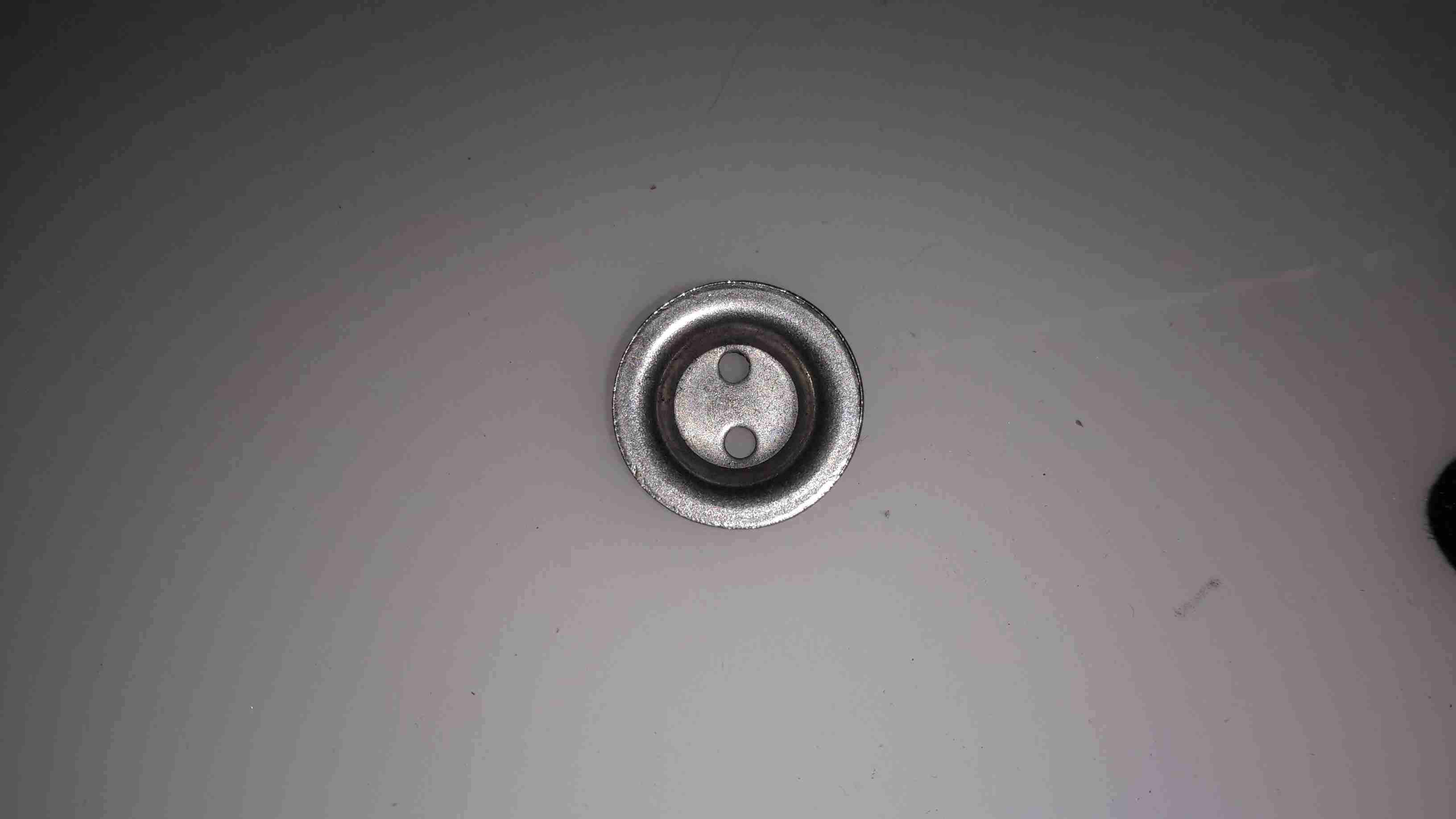
Working Electrode Components
Next up is the working electrode assembly, this also forms the seal on the can when it’s crimped, along with insulating it from the counter electrode & external can. The small disc third from left is supposed to be the electrode, which in these cells should be loaded with Platinum. Considering where else they’ve skimped in this unit, I’ll be very surprised if it’s anything except graphite.
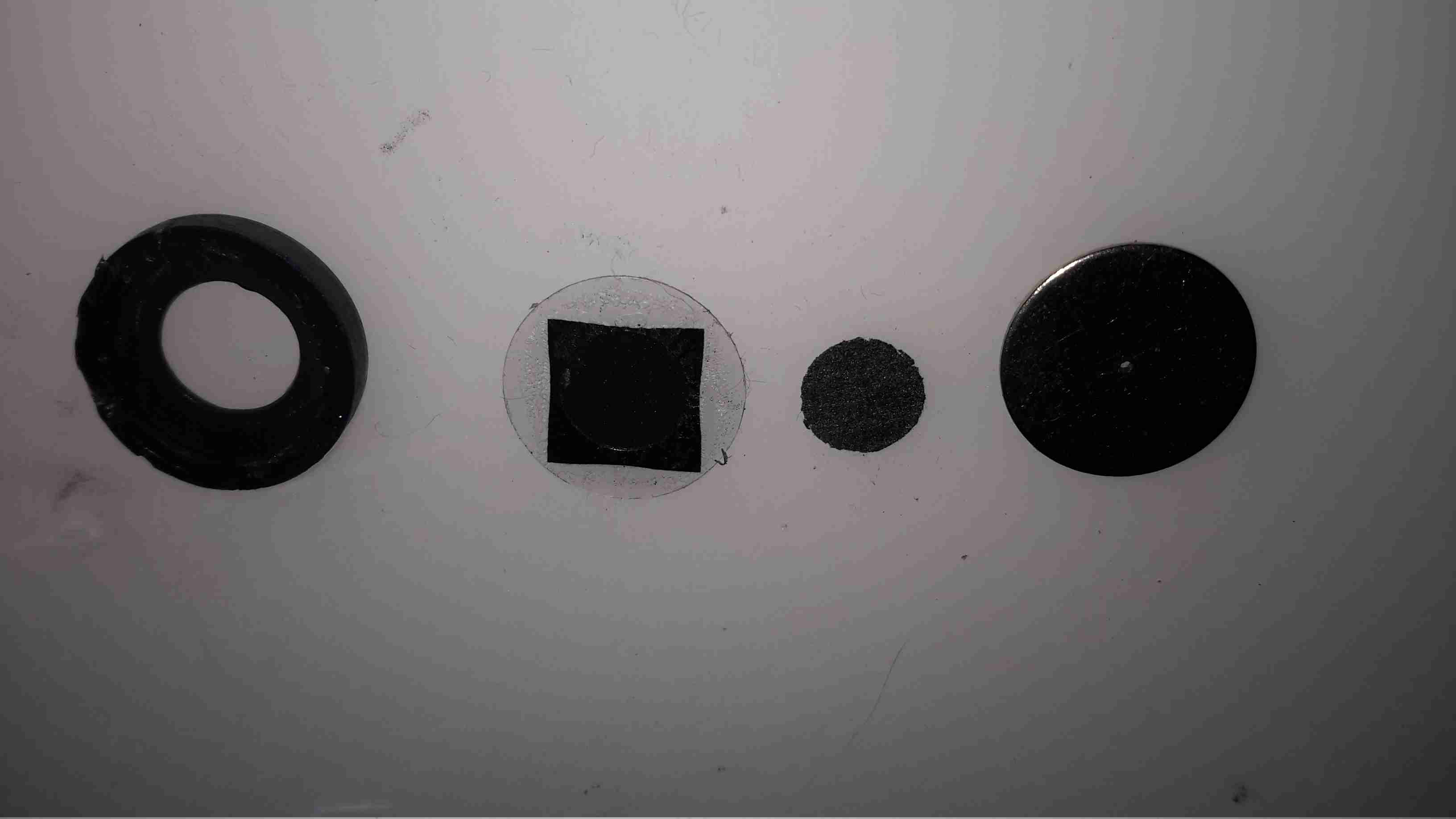
Counter Electrode
Next up is the counter electrode, which is identical to the first, working electrode. Again I doubt there’s any precious metals in here.
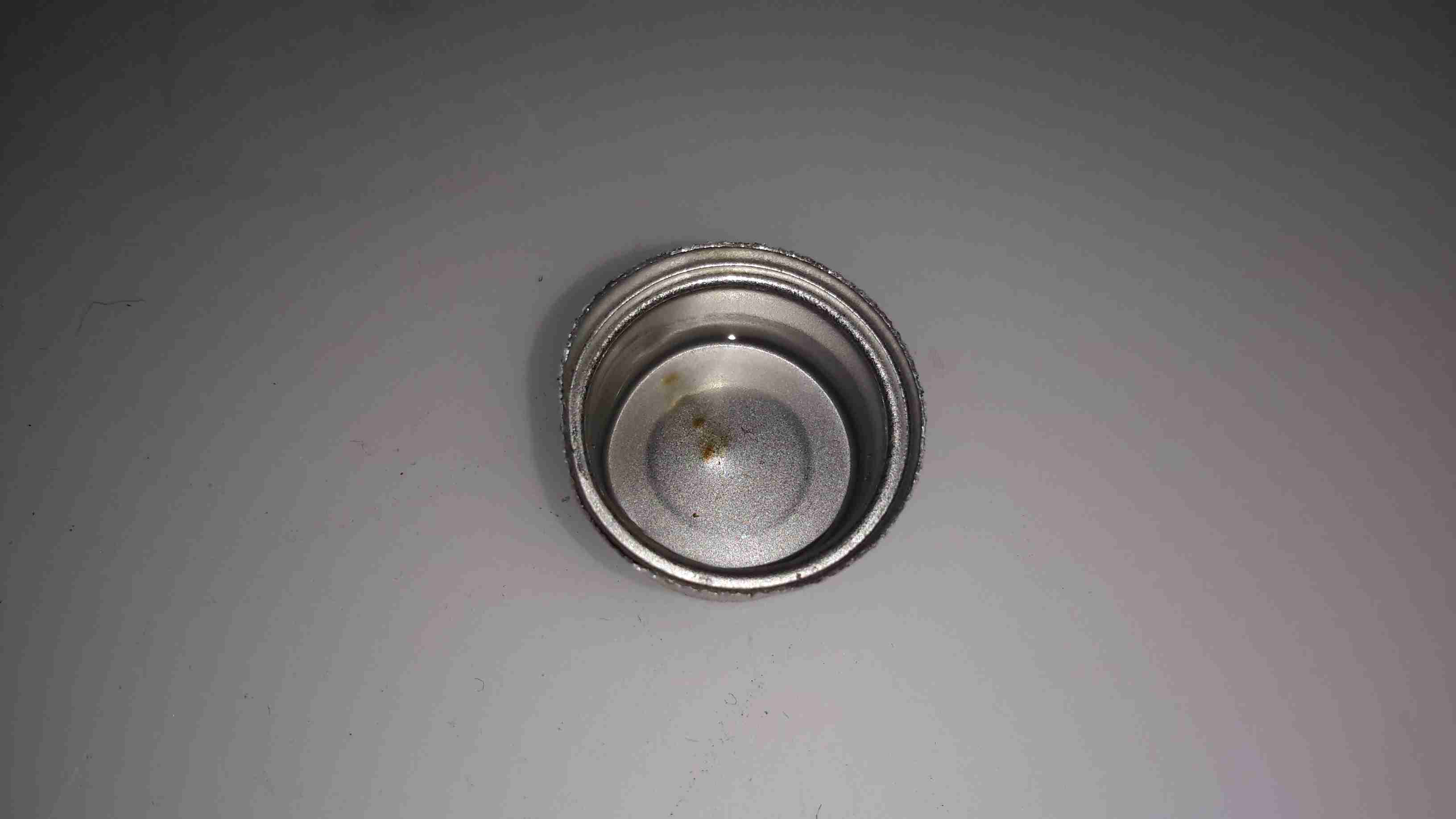
Backplate
Another steel backplate finishes off the cell itself, and keeps most of the liquid out, just making sure everything stays moist.
Rear Can & Reservoir
Finally, the rear of the cell holds the reservoir of liquid electrolyte. This is supposed to be Sulphuric Acid, but yet again they’ve skimped on the cost, and it’s just WATER.
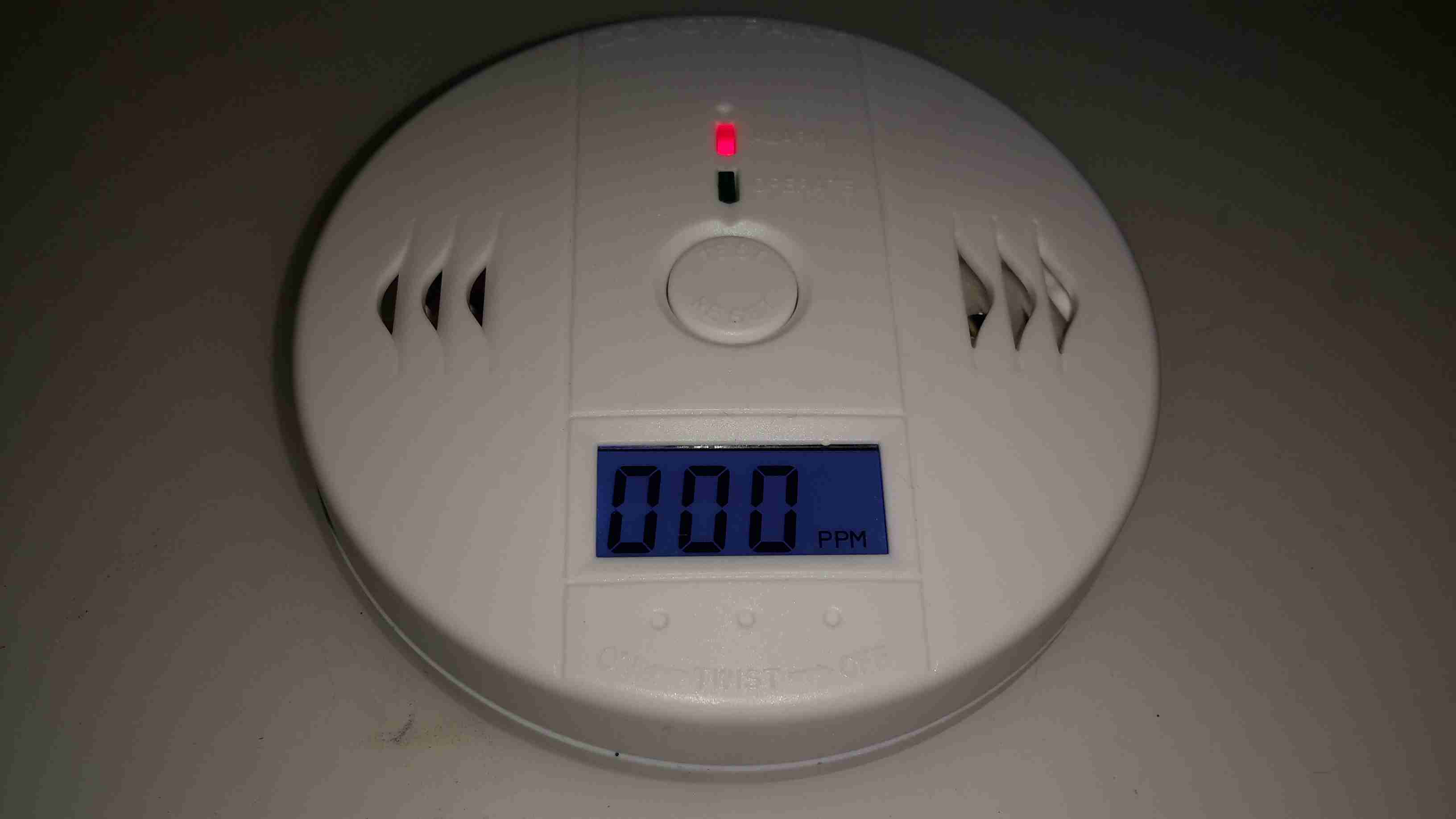
It’s now not surprising that it wouldn’t give me any readings, this cell never would have worked correctly, if at all, without the correct electrolyte. These cheap alarms are dangerous, as people will trust it to alert them to high CO levels, when in fact it’s nothing more than a fancy flashing LED with an LCD display.
Ironically enough, when I connected a real electrochemical CO detector cell to the circuit from the alarm, it started working, detecting CO given off from a burning Butane lighter. It wouldn’t be calibrated, but it proves everything electronic is there & operational. It’s not surprising that the corner cut in this instance is on the sensor cell, as they contain precious metals & require careful manufacturing it’s where the cost lies with these alarms.
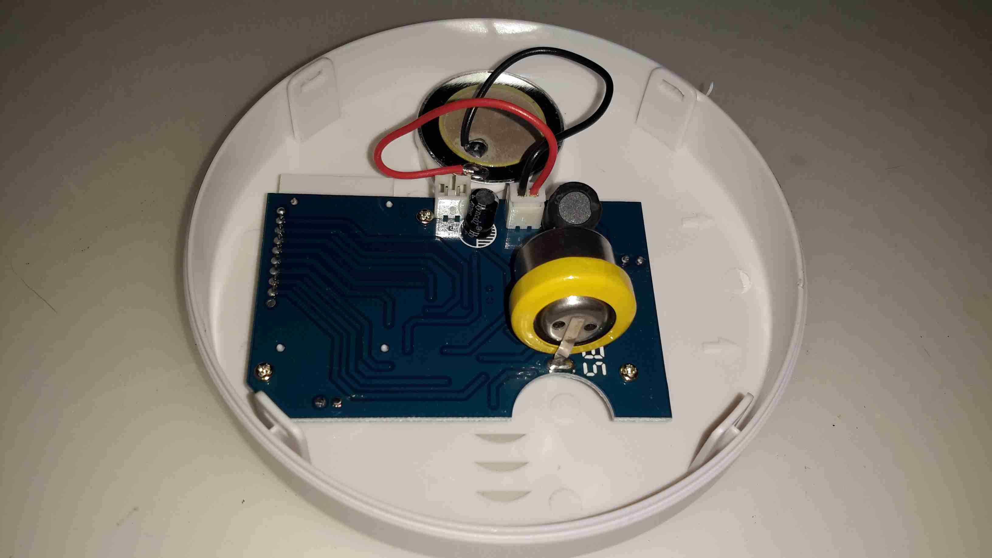
I was looking around eBay for decent deals on a branded CO alarm, and came across these for next to no money, so I thought I’d grab one just to see how bad they could be.
Alarm Opened
Popping the casing open shows the very small circuit board inside, with the CO sensor cell on the right. I can’t find any manufacturer information on this cell, nor can I find a photo of anything similar on the intertubes, so no specifications there. The other parts are pretty standard, a Piezo sounder & it’s associated step-up transformer to increase the loudness.
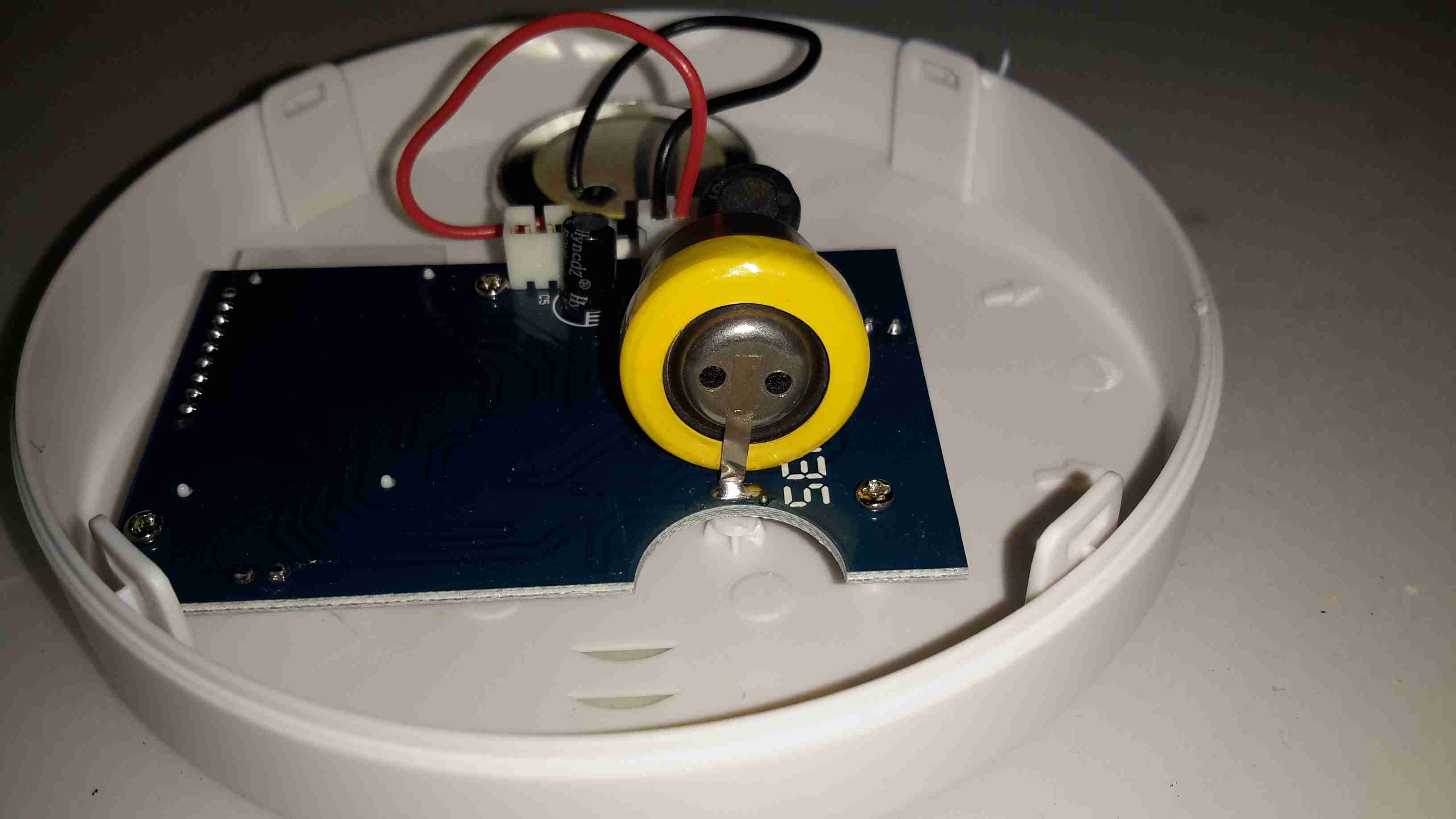
Sensor Closeup
The sensor cell has the usual opening in the end to allow entry of gas.
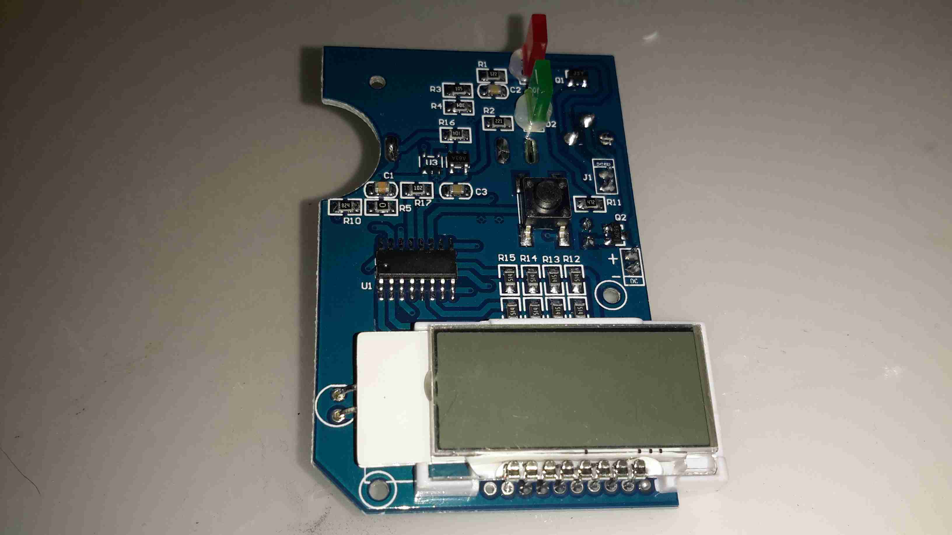
Main PCB
The other side of the board doesn’t reveal much, just an LCD, a couple of LEDs, a pair of transistors, Op-Amp for the sensor & a main microcontroller.
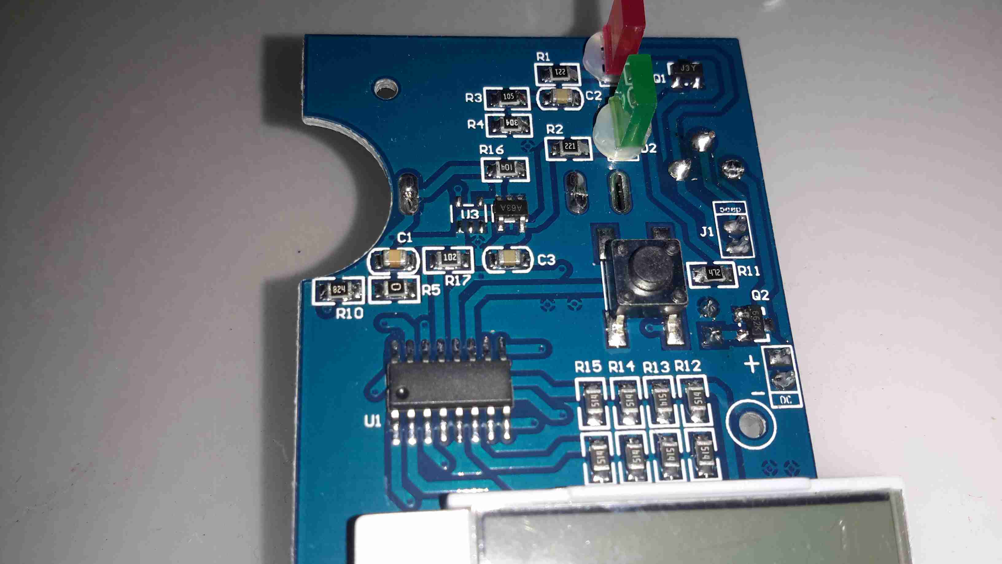
MCU
The microcontroller isn’t marked unfortunately. It’s not had the number scrubbed off, it’s just never been laser marked with a part number. Above the micro is a SOT-23 LM321 low-power Op-Amp which does the signal conditioning for the CO sensor.
I tried to make this alarm trigger with the exhaust from the Eberspacher heater, which on a well-made branded alarm registered a reading of 154ppm after a few minutes. In the case of this alarm though, I couldn’t make it trigger at all, no matter how long I exposed it to hydrocarbon exhaust gases. I won’t be trusting this one then!
Nothing quite like a piece of safety equipment that doesn’t work correctly from new!
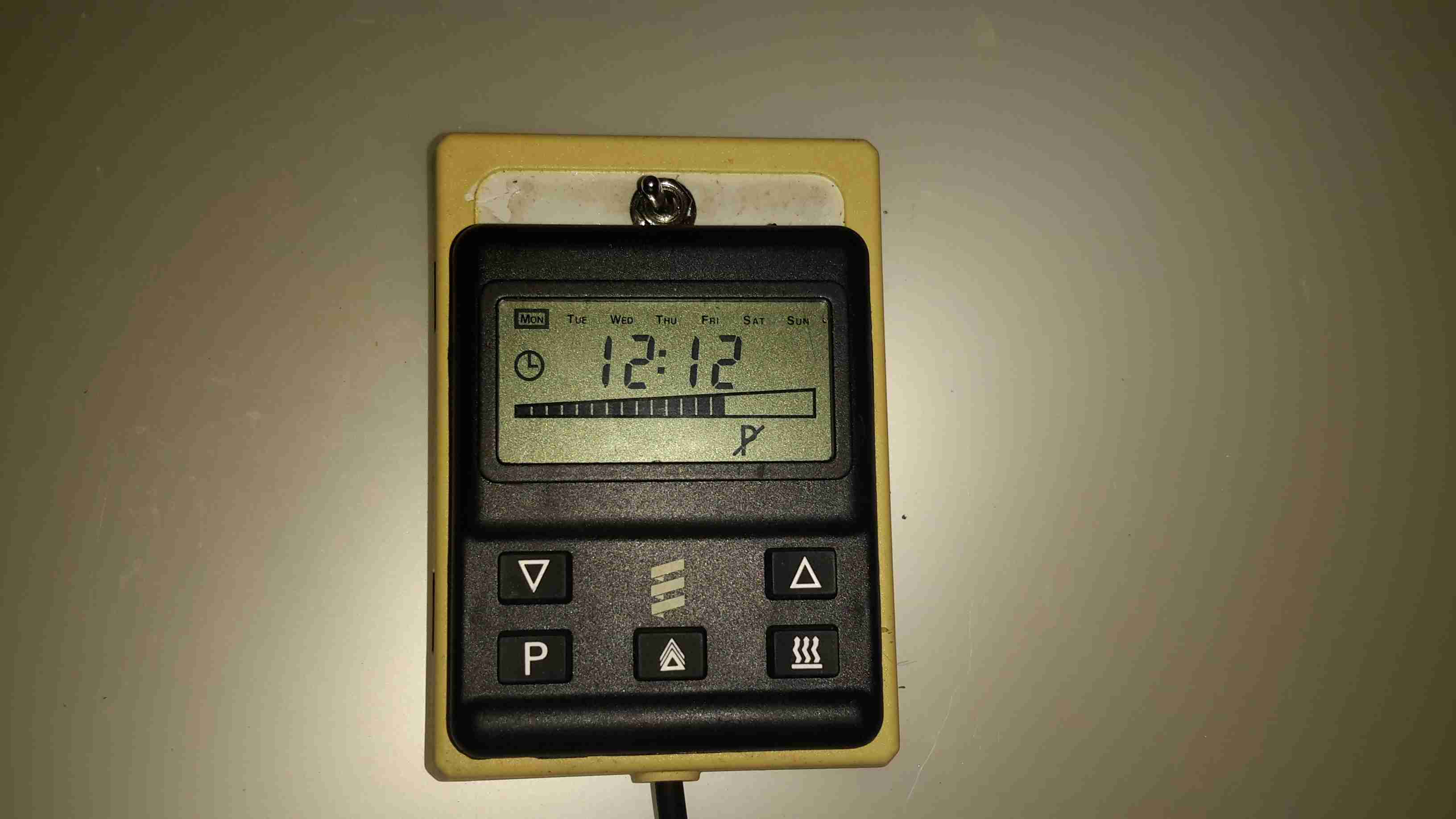
The Eberspacher heaters can be controlled with a single switch, but it’s more convenient to have some temperature control & the option of a timer. Above is an ex-BT 701 series controller, with built in 7-day programmer. Being an ex-BT van version though, it’ll only switch the heater on for 1 hour at a time.
To get around this slight niggle, I fitted a bypass toggle switch.
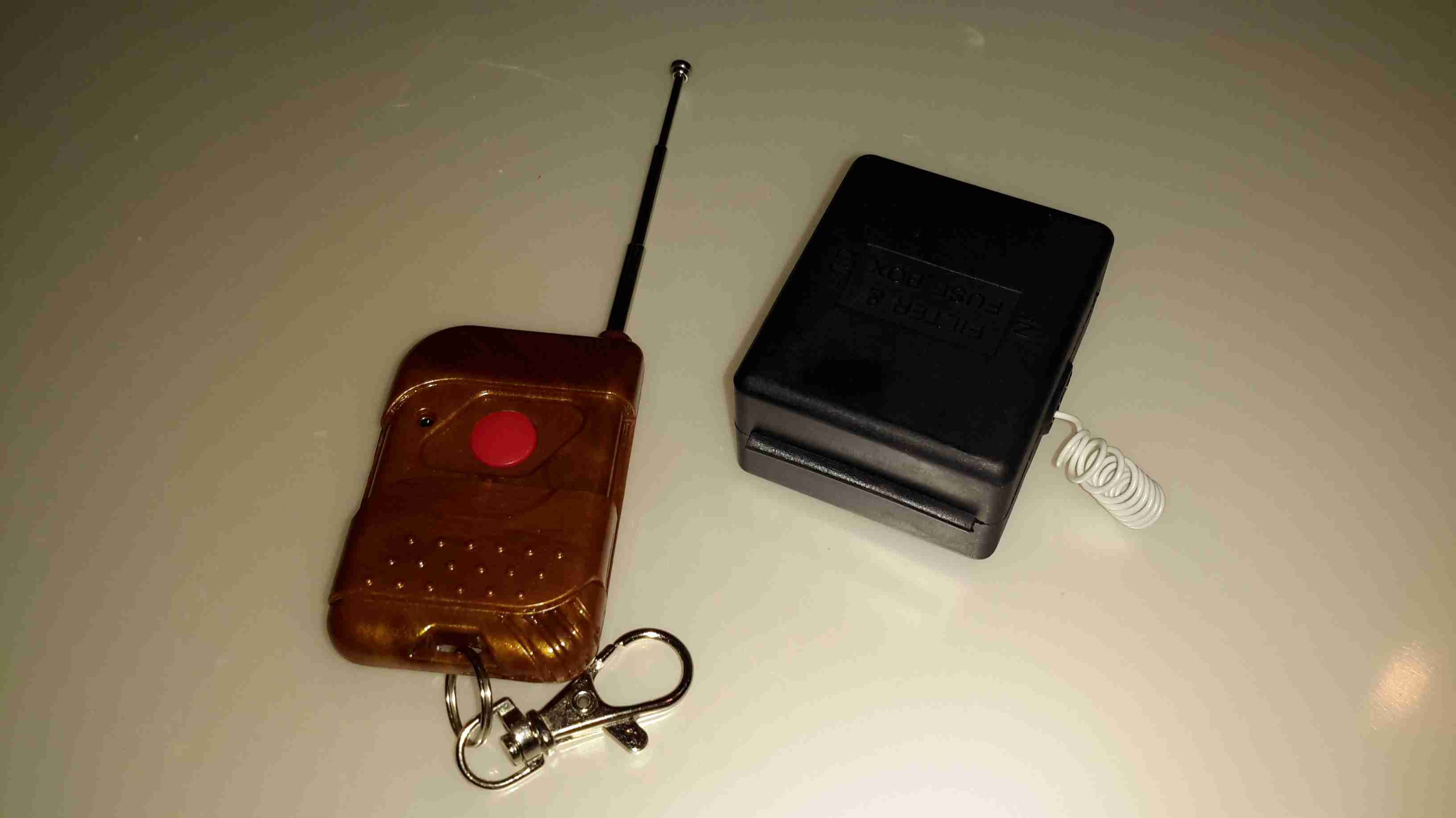
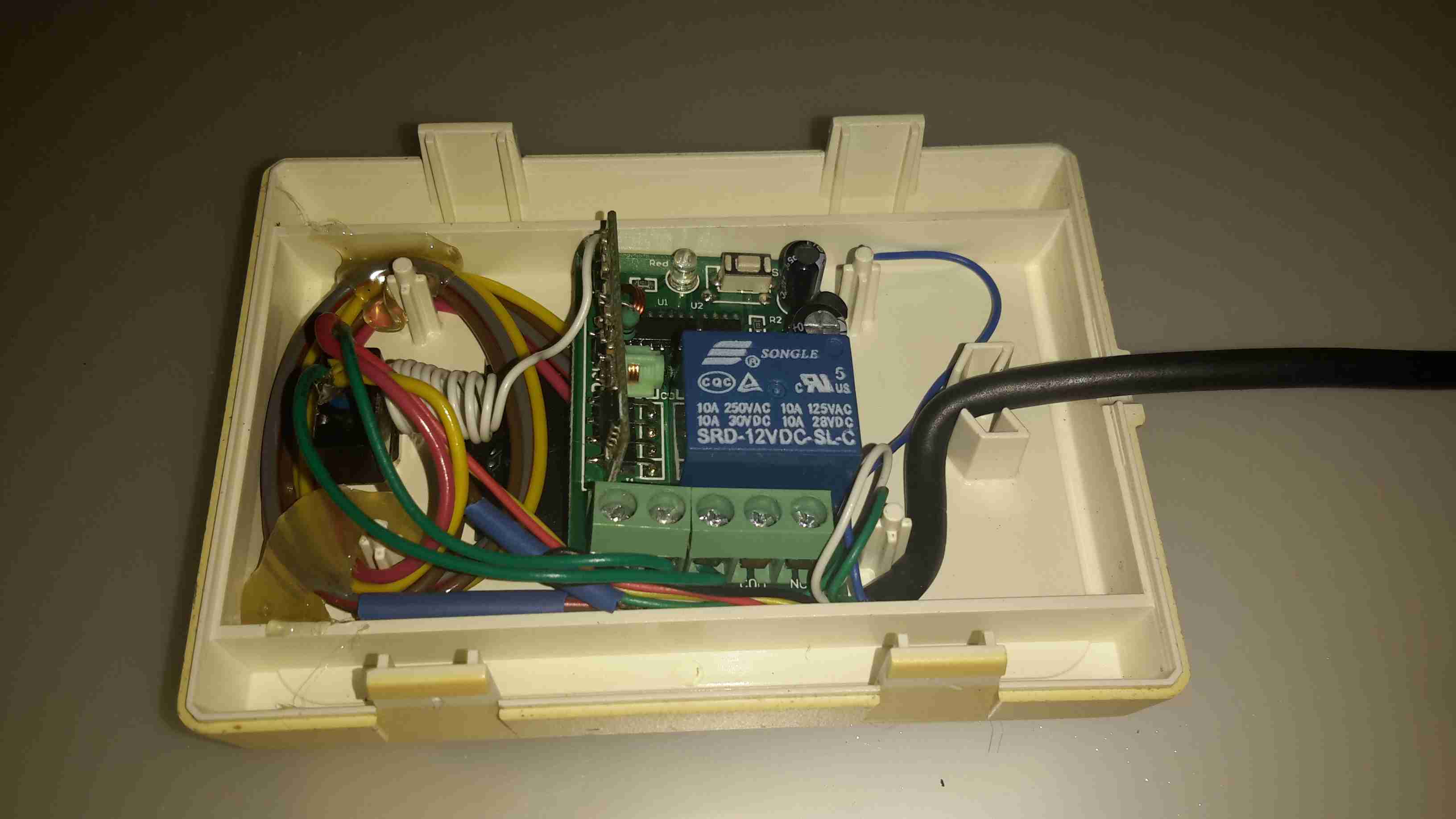
Remote Control
For a bit of extra convenience, I got an RF remote controlled relay module from eBay (£5).
This allows me to switch things on remotely, so I can return to a nice toasty tent while camping.
There is an official RF remote for Eberspacher heaters, but I’ve no doubt they’re hideously expensive.
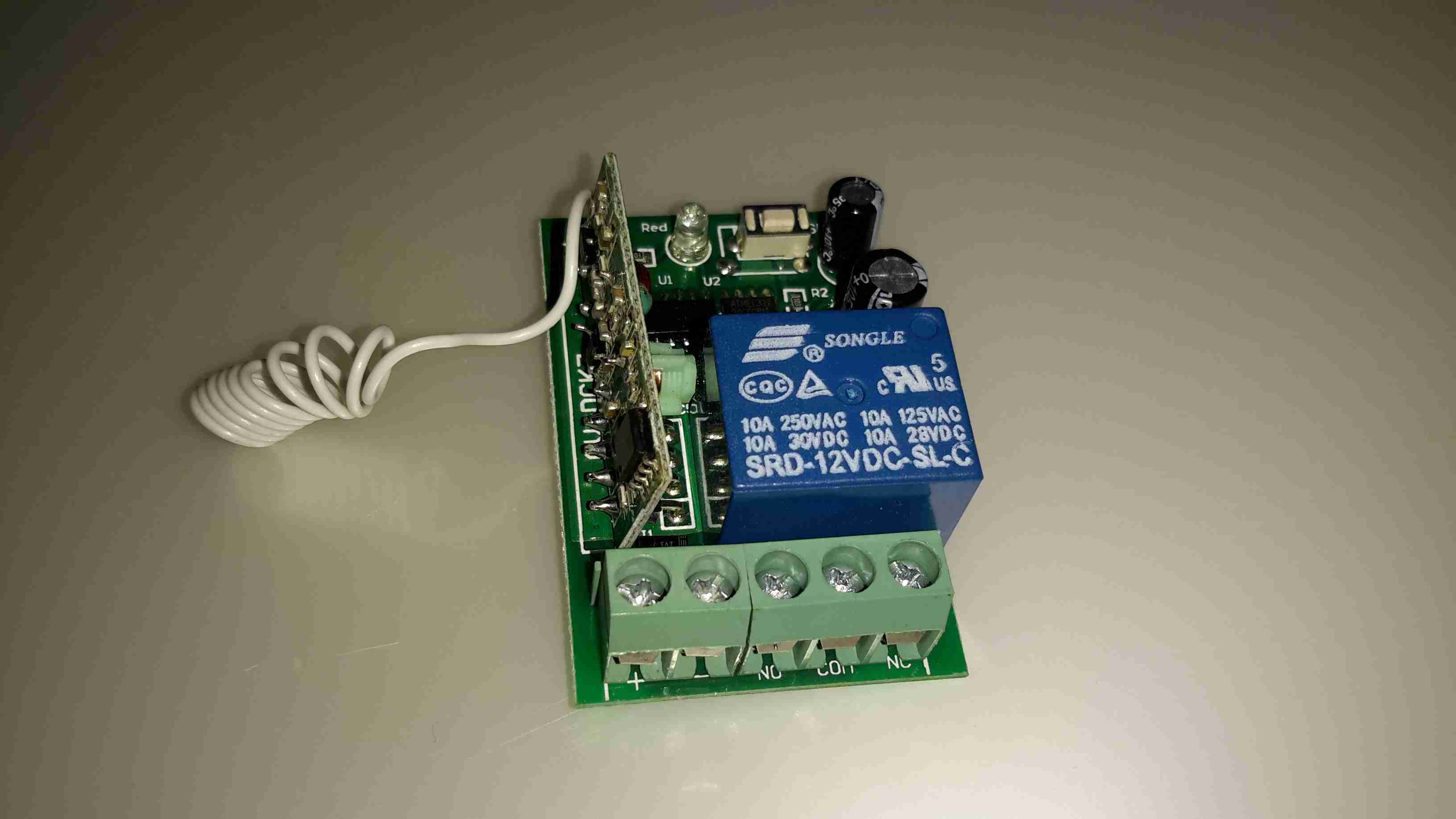
RF Receiver
Here’s the receiver PCB, there’s an EEPROM & a microcontroller onboard for handling the codes the remotes send, but as the number has been scrubbed off the micro, no data there. This uses a standard RF receiver module.
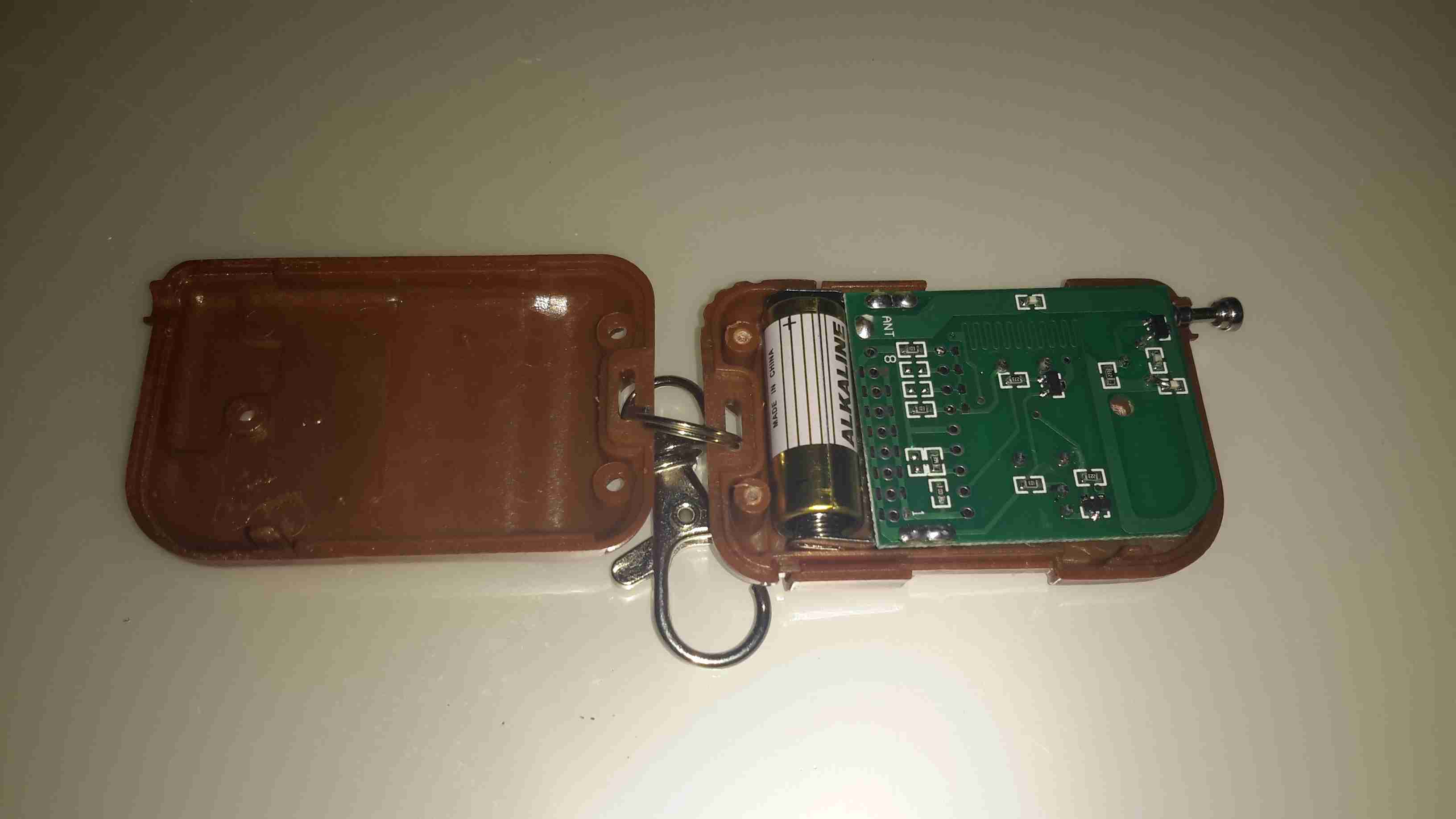
RF Remote
Here’s the remote itself, this uses a 12v battery instead of a 3v lithium cell. A little of a pain since these batteries can be a bit pricey.
As this RF system operates on 315MHz, it’s technically illegal in the UK, but I was unable to find a 433MHz version with the features required. Nevermind ;).
Controller Internals
Here’s the module installed in the controller casing. I have since run the antenna wire around the edge of the case to try & get the furthest range on receive. The relay contacts are just paralleled across the bypass switch, so when the relay energizes the heater fires up.
Luckily the thermostatic control portion of the 701 programmer is operational even when heating mode is not active.
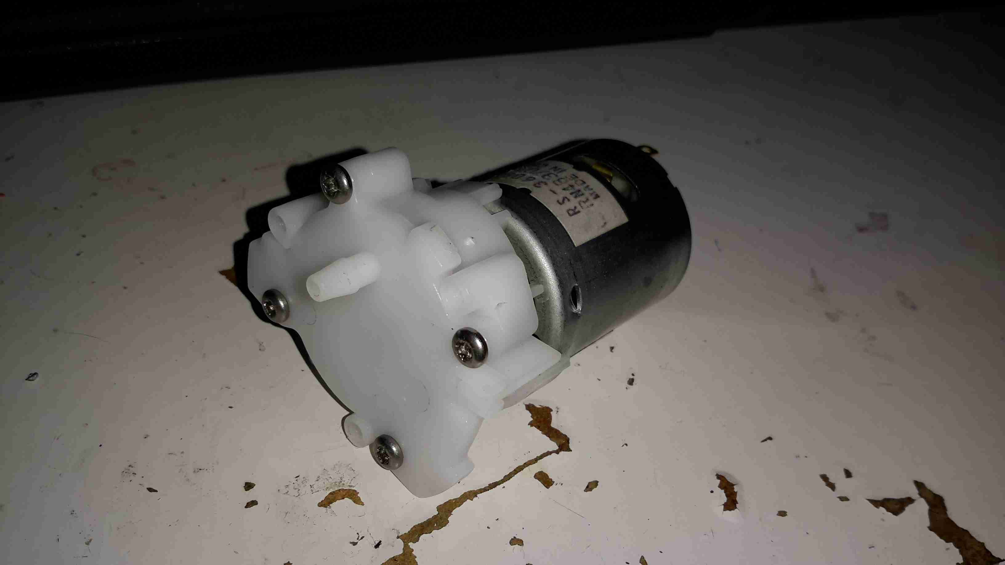
I got one of these to test since I’ve been in need of some small DC pumps for fluid transfer use. At £2 I can definitely afford to experiment.
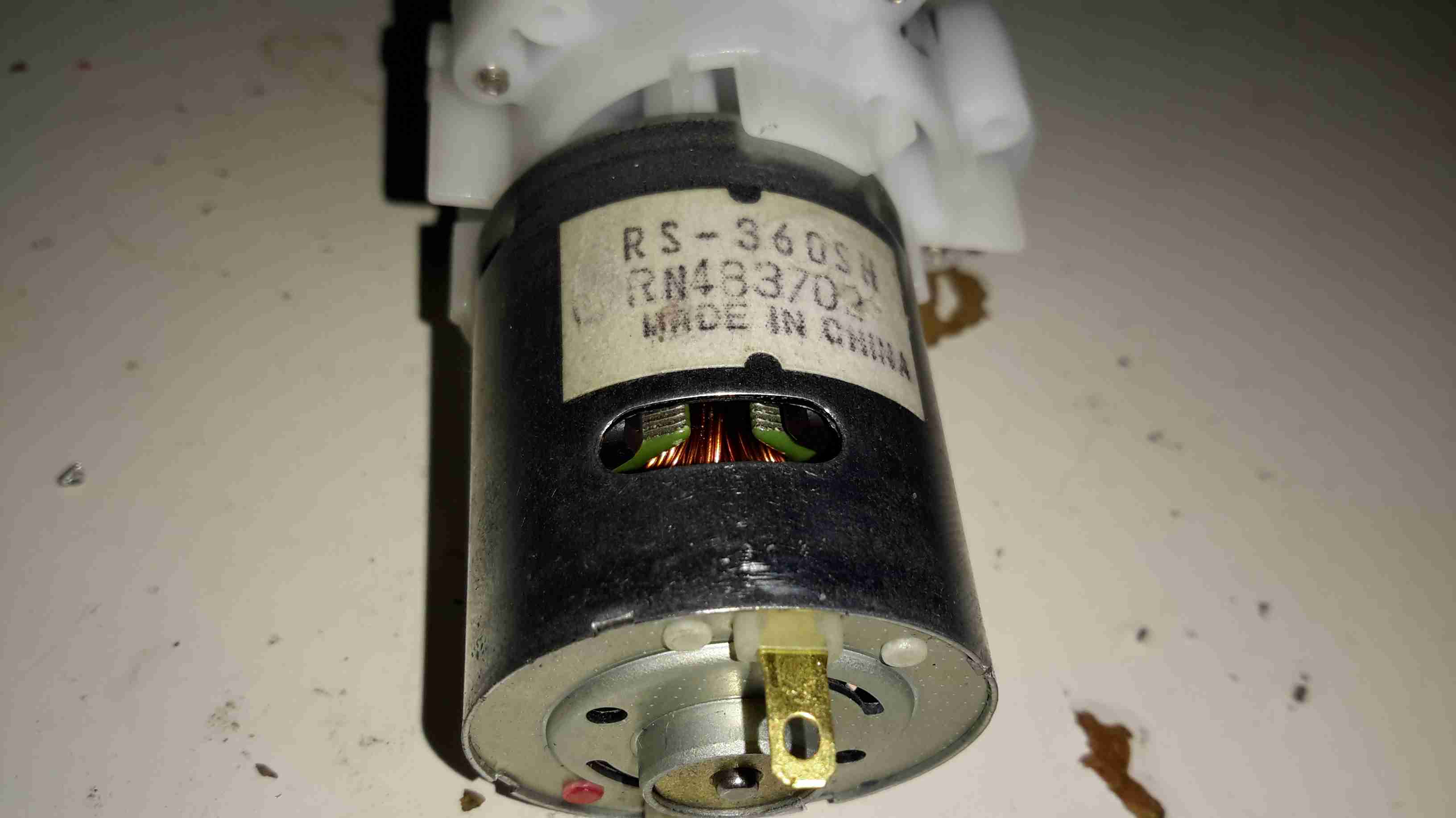
DC Motor
On the eBay listing, these pumps are rated at 3-12v DC, (I thought that was a bit wide of an operating range), I looked up the motor, an RS-360SH on Mabuchi’s website, they only have models in this range rated at 7.2v & 24v. Judging by the size of the windings on the armature & the fact that after a few minutes operation on 12v it gets rather hot, I’m going to say this is the 7.2v motor.
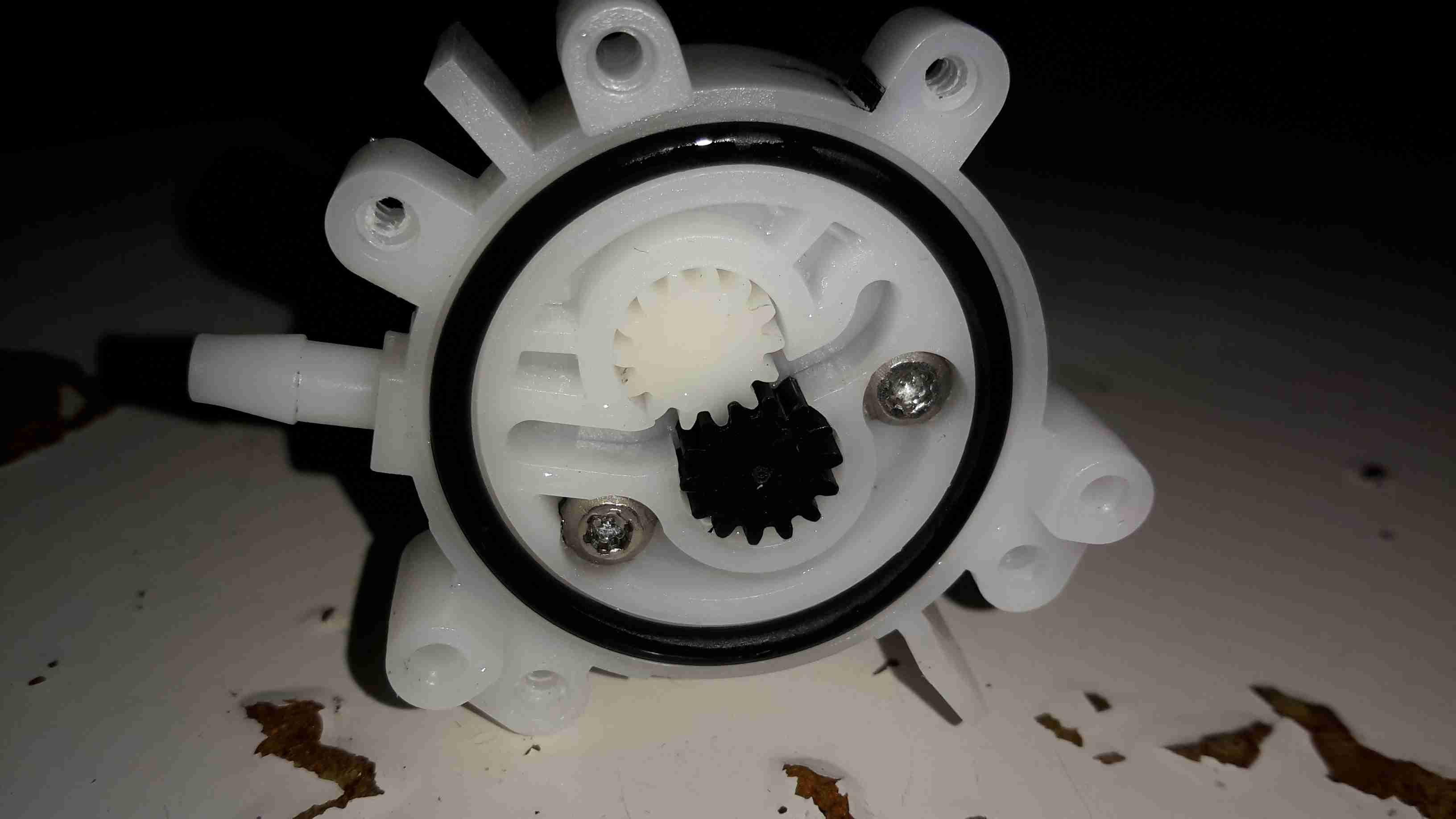
Pump Gears
Removing the screws releases the end cover & the pair of gears inside. This operates like any other hydraulic gear motor, albeit with much wider tolerances. It has no capability to hold pressure when the power is removed, and can be blown through easily.
Flow & pressure under power are quite good for the pump’s size, even though it’s noisy as hell.
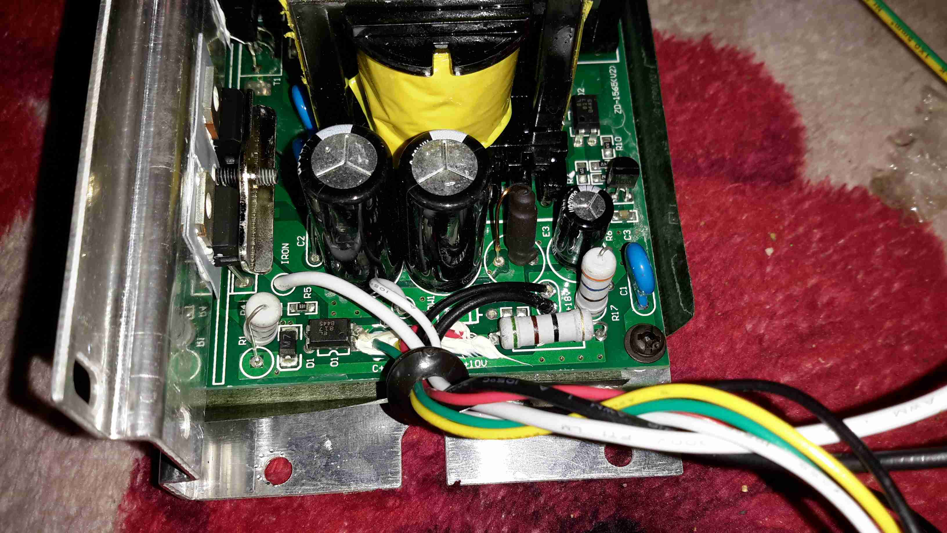
Inkeeping with everything else in my shack being low voltage operated, I had planned from the outset to convert the desoldering station to 12v operation. It turns out this has been the easiest tool to convert in my shack so far.
PSU Outputs
The factory SMPS is a fairly straightforward 18v 12A unit, with only a single small oddity: the desoldering gun’s heating element is controlled from inside the supply.
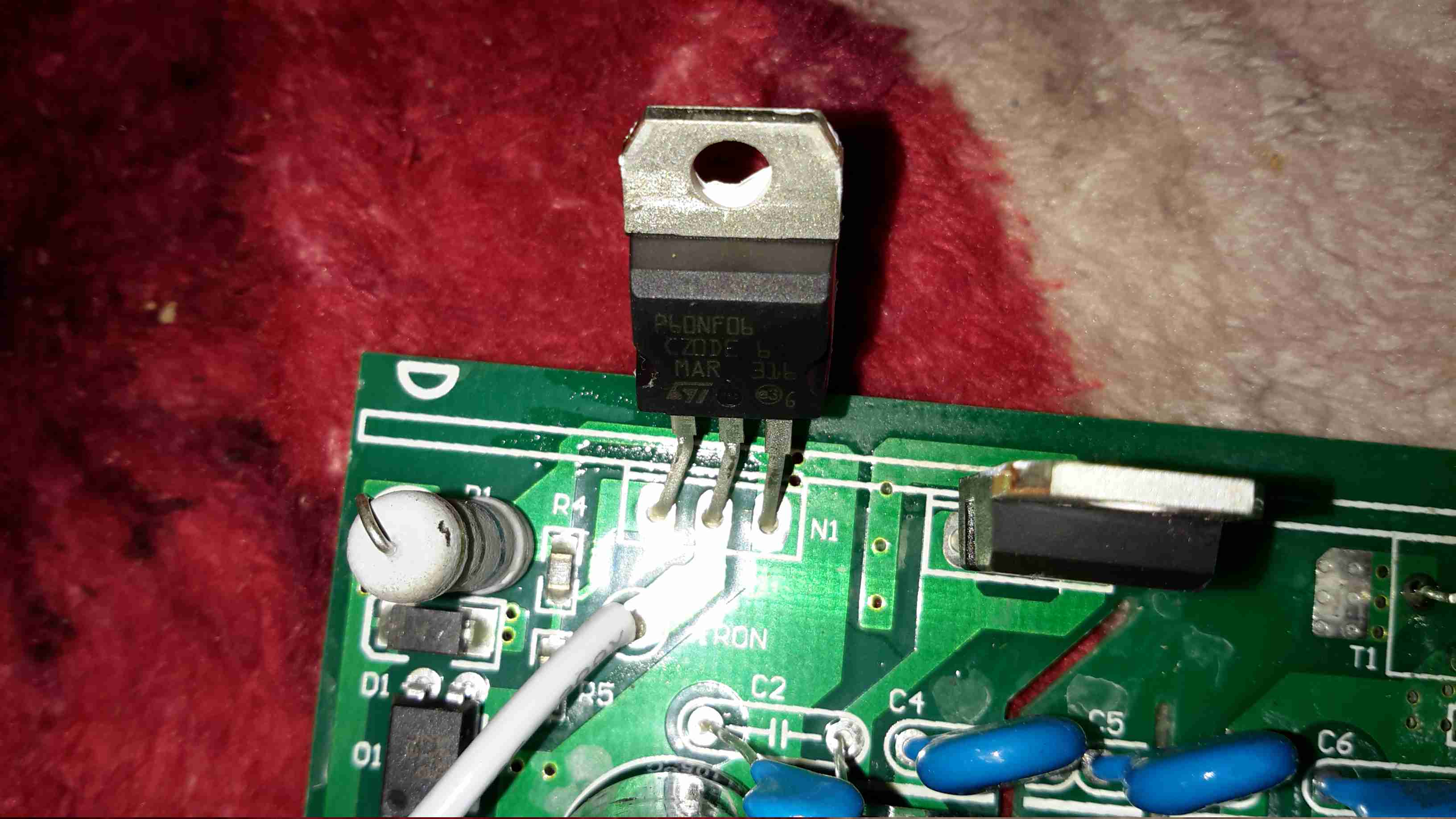
Iron MOSFET
Next to the output rectifier on the heatsink is a large MOSFET, in this case a STP60NF06 from ST Micro. This is a fairly beefy FET at 60v & 60A capacity, RDS On of <0.016Ω.
This is driven via an opto-isolator from the main logic board. I’ve not yet looked at the waveform on the scope, but I suspect this is also being PWM’d to control temperature better when close to the set point.
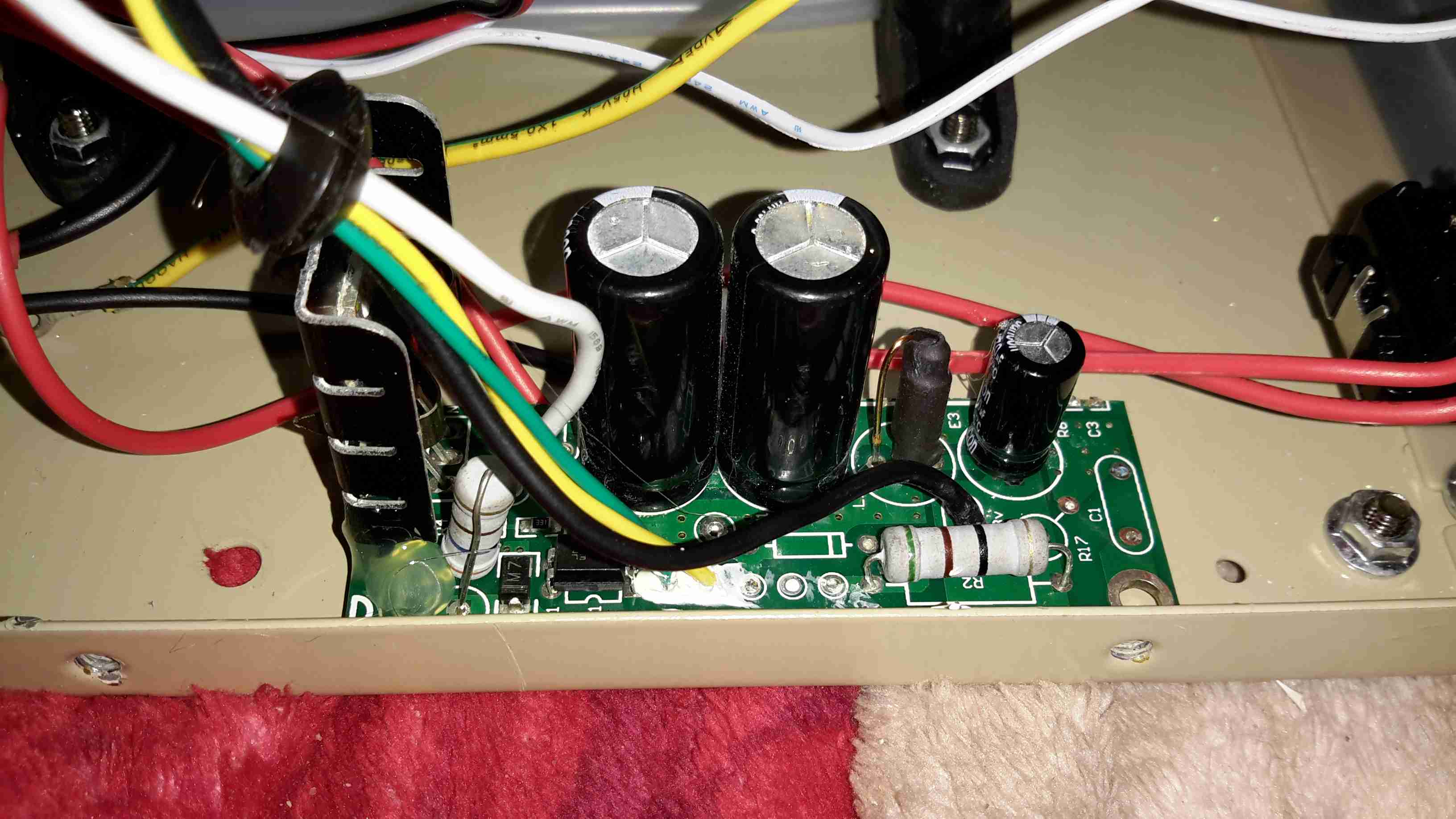
Iron Element Controller
Rather than fire up the soldering iron & build a new element controller circuit (Lazy Mode™), I opted to take a saw to the original power supply. I cut the DC output section of the PCB off the rest of the supply & attached this piece back to the frame of the base unit. I also added a small heatsink to the MOSFET to make sure it stays cool.
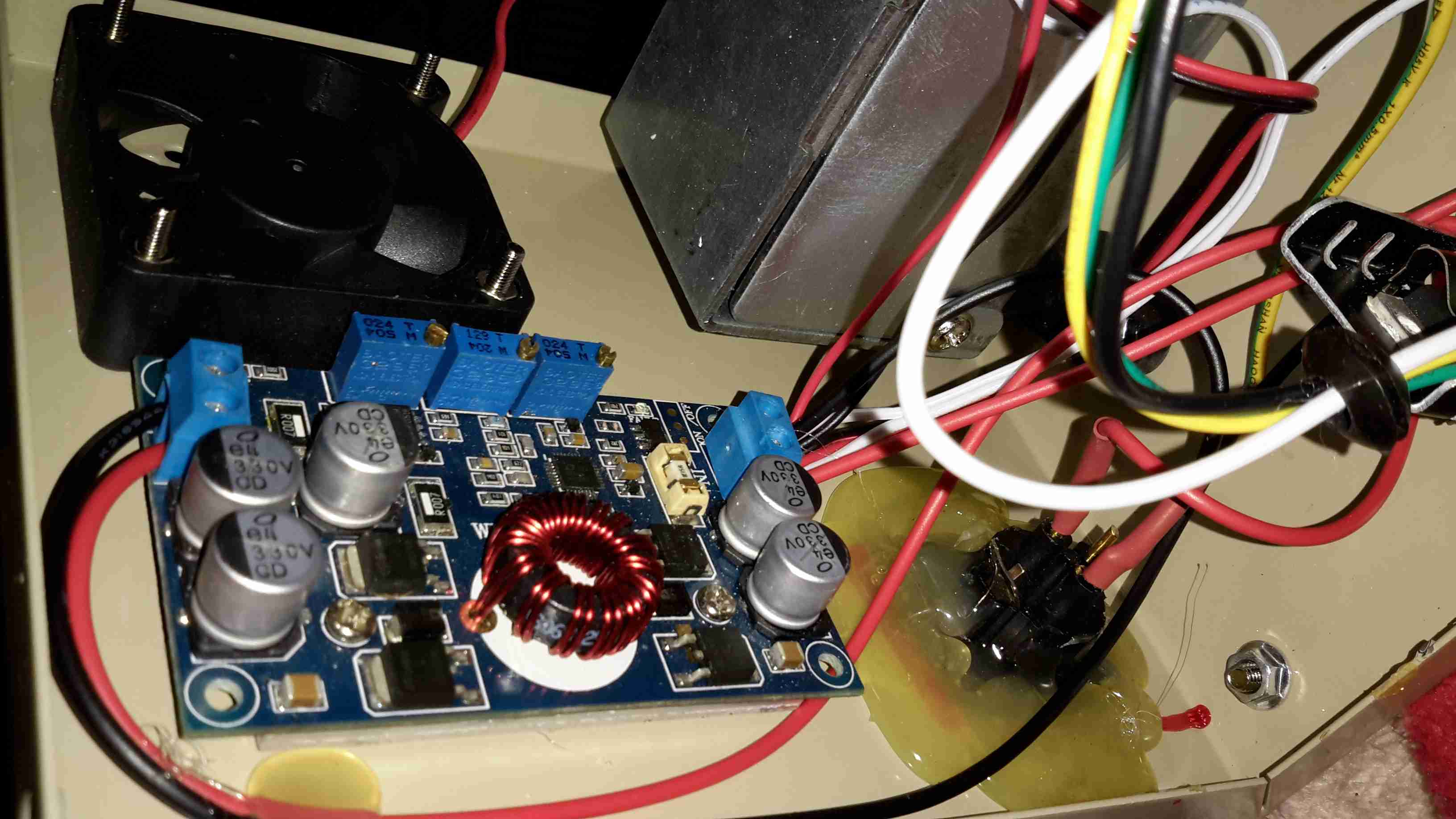
12v Power Supply
Since the fan & vacuum pump are both already 12v rated, those are connected directly to the DC input socket, that I’ve installed in place of the original IEC mains socket. The 18v for the heating element is generated by a 10A DC-DC converter, again from eBay.
Oddly, the iron itself is rated at 24v 80W, but the factory supply is only rated to 18v. I’m not sure why they’ve derated the system, but as the station already draws up to 10A from a 13.8v supply, increasing the voltage any further would start giving my DC supplies a problem, so it can stay at 18v for now.
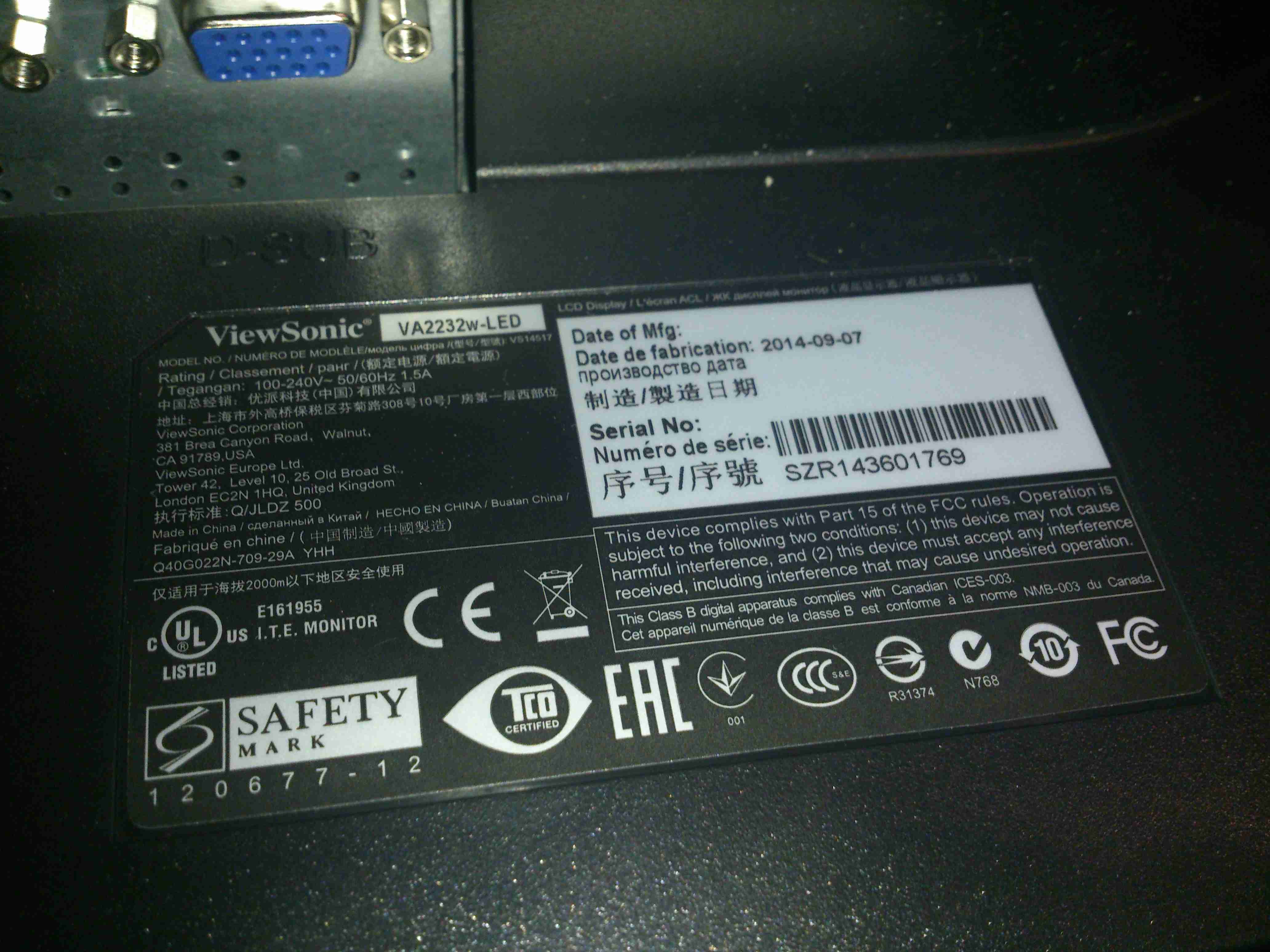
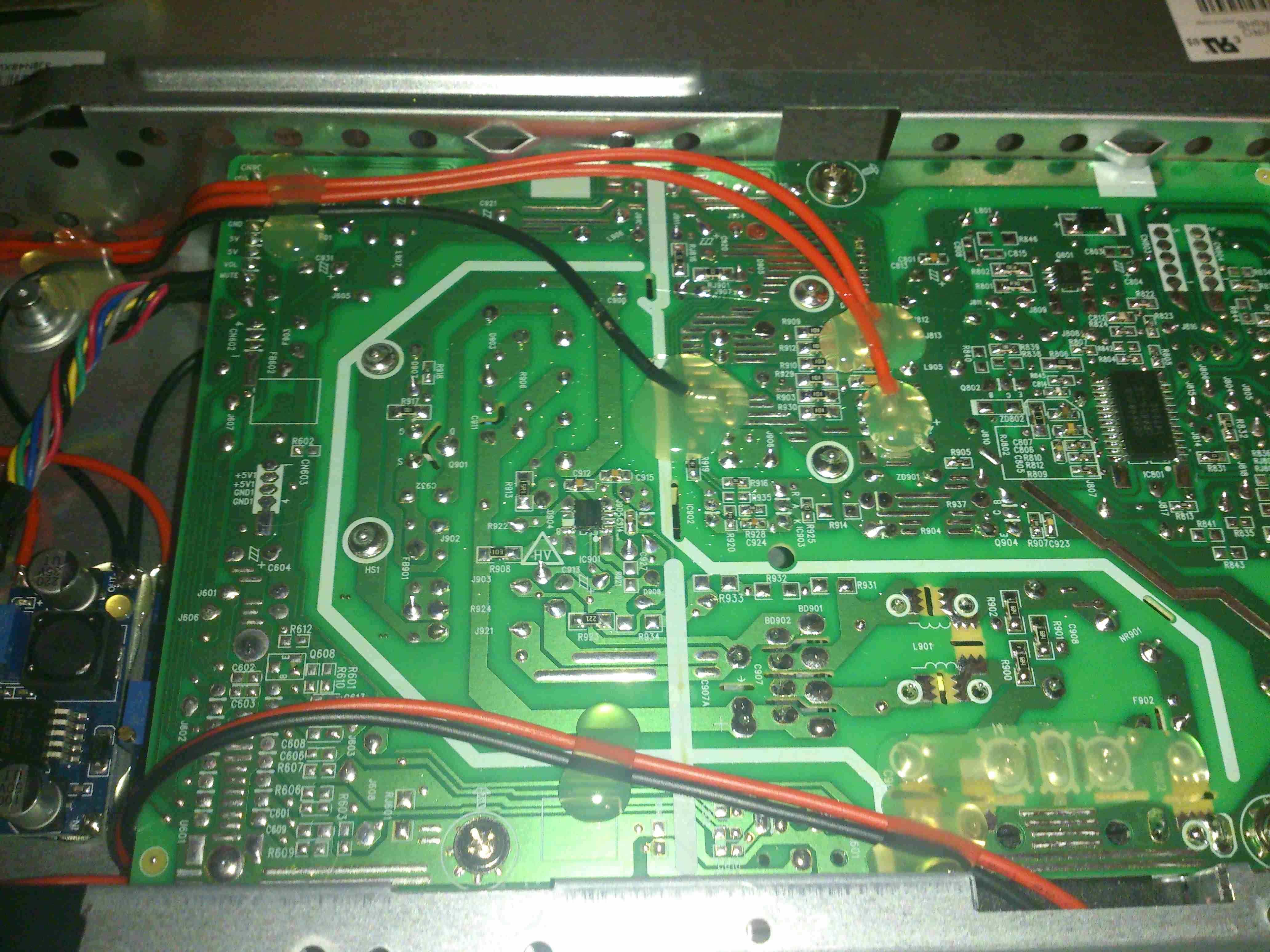
On the quest to get things on board replaced that are heavy users of power, the monitor in the main cabin was next. The original CCFL-backlit monitor was very heavy on 12v power, at 5A. This meant falling asleep watching TV would result in severely flattened batteries.
Replacement with a suitable LED-backlit monitor was definitely required. The cheapest on eBay was a ViewSonic VA2232W-LED, so I took to work converting it from 240v to 12v operation.
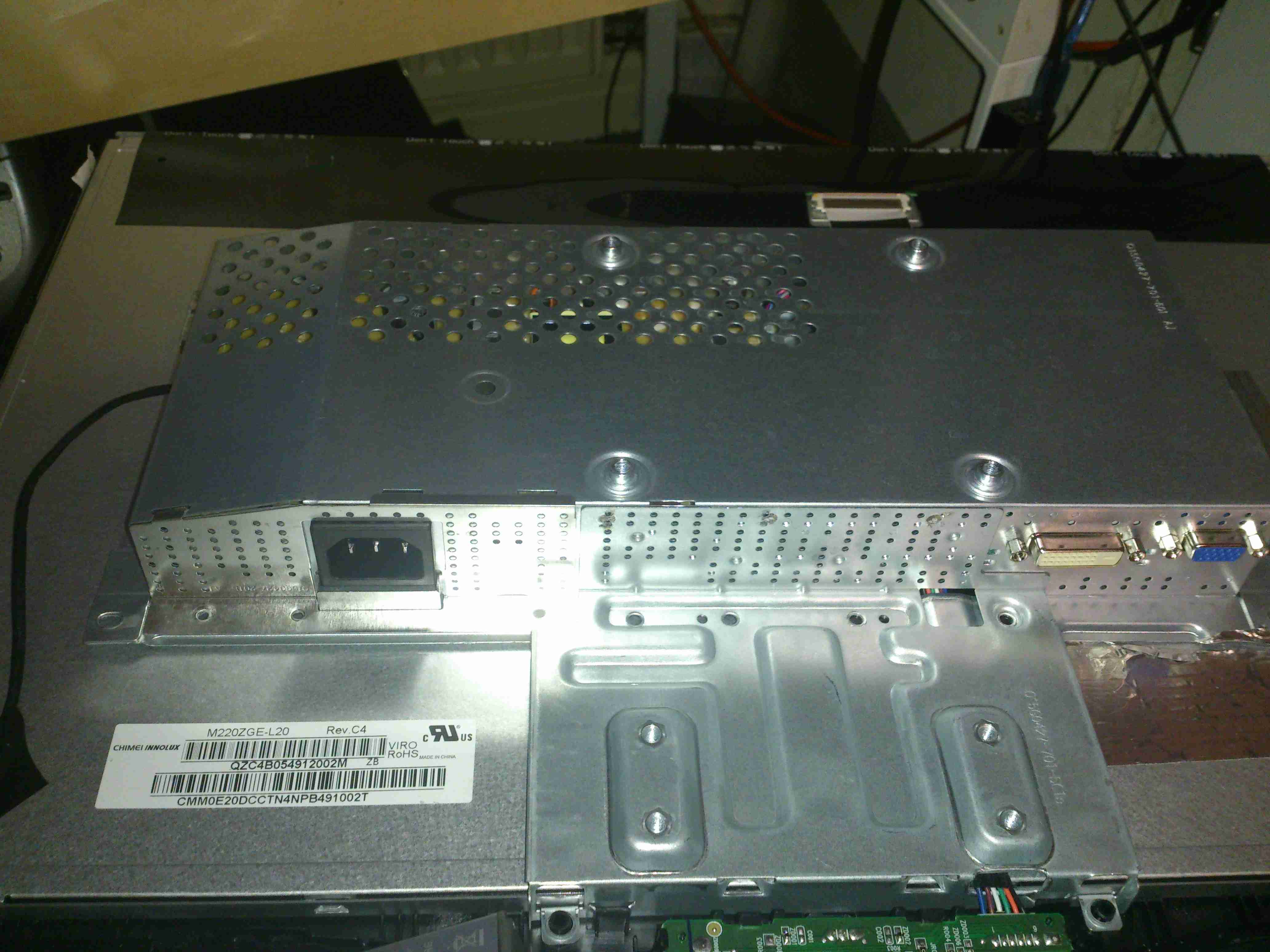
Back Cover Removed
There are no screws holding these monitors together, so a spudger & frequent swearing got the back off. The shield holding the circuitry is also not screwed down, only attached to the back of the LCD panel with aluminium shielding tape.
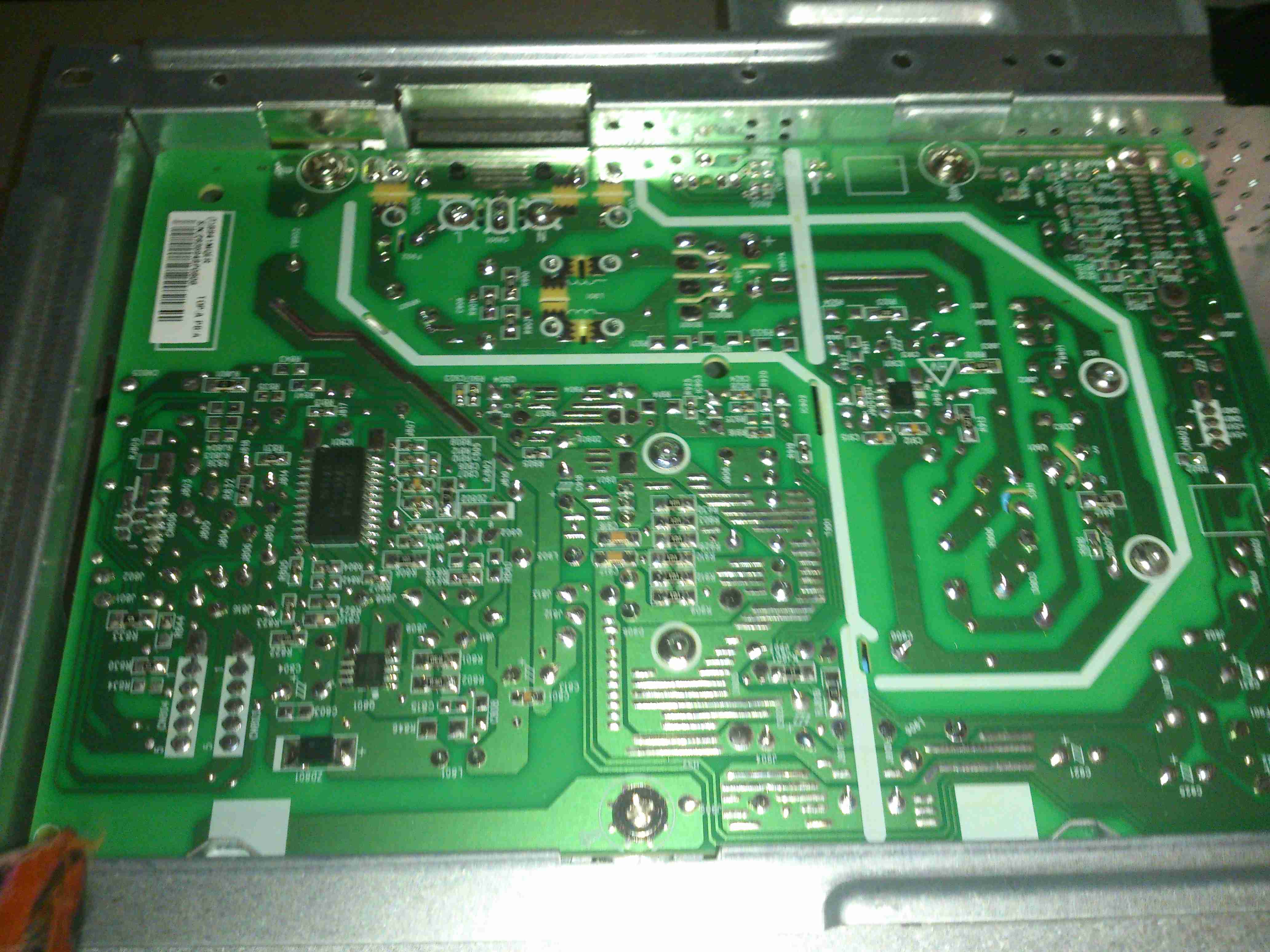
Power PCB Trackside
Once the tape has been cut, the main power board is accessible. The large IC on the left is the main backlight LED driver.
In this case the monitor requires a pair of rails from the supply, 18.5v for the backlight circuitry & 5v for the logic.
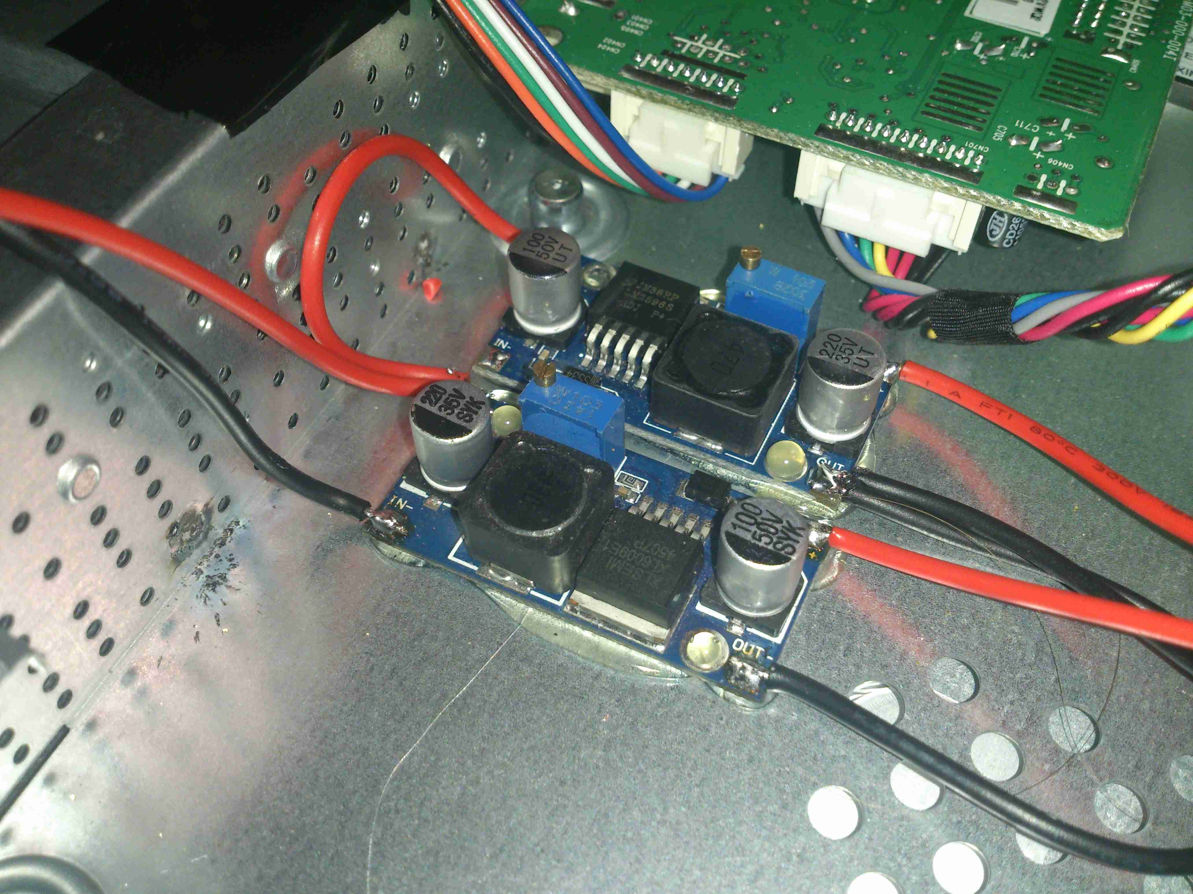
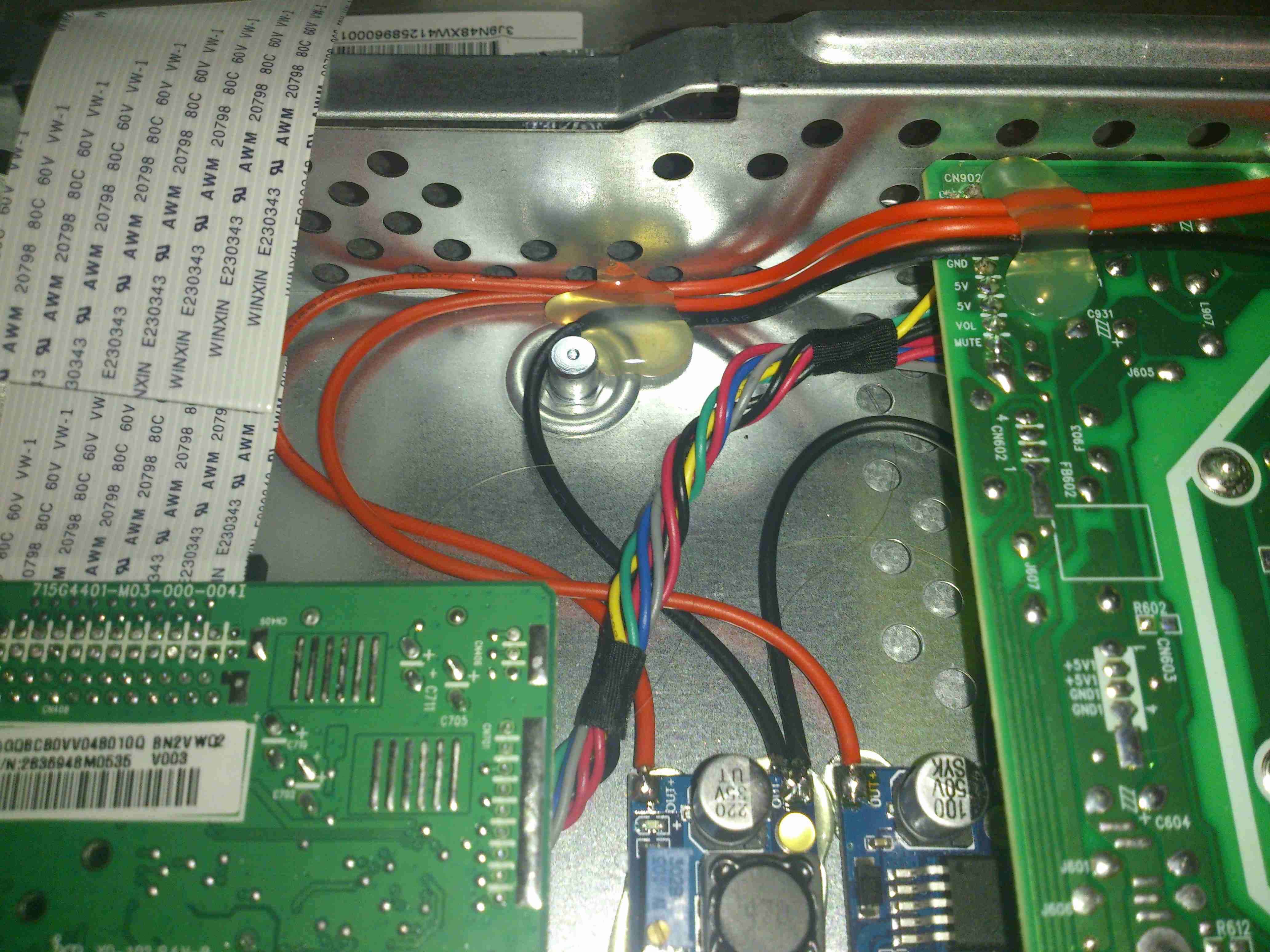
DC-DC Regulators
A pair of DC-DC converters has been fitted in the small space between the power & control boards.
PCB Connection Points
To save me some work & keep maximum compatibility, I’ve not modified the existing supply, just attached the new DC-DC converter outputs onto the corresponding outputs of the factory PSU. The 12v input leads are routed out of the same gap as the mains IEC connector, with some hot glue over the mains input solder points to provide some more insulation.
Wiring Tidied
The wiring is tidied up with hot glue so the back cover will go back on.
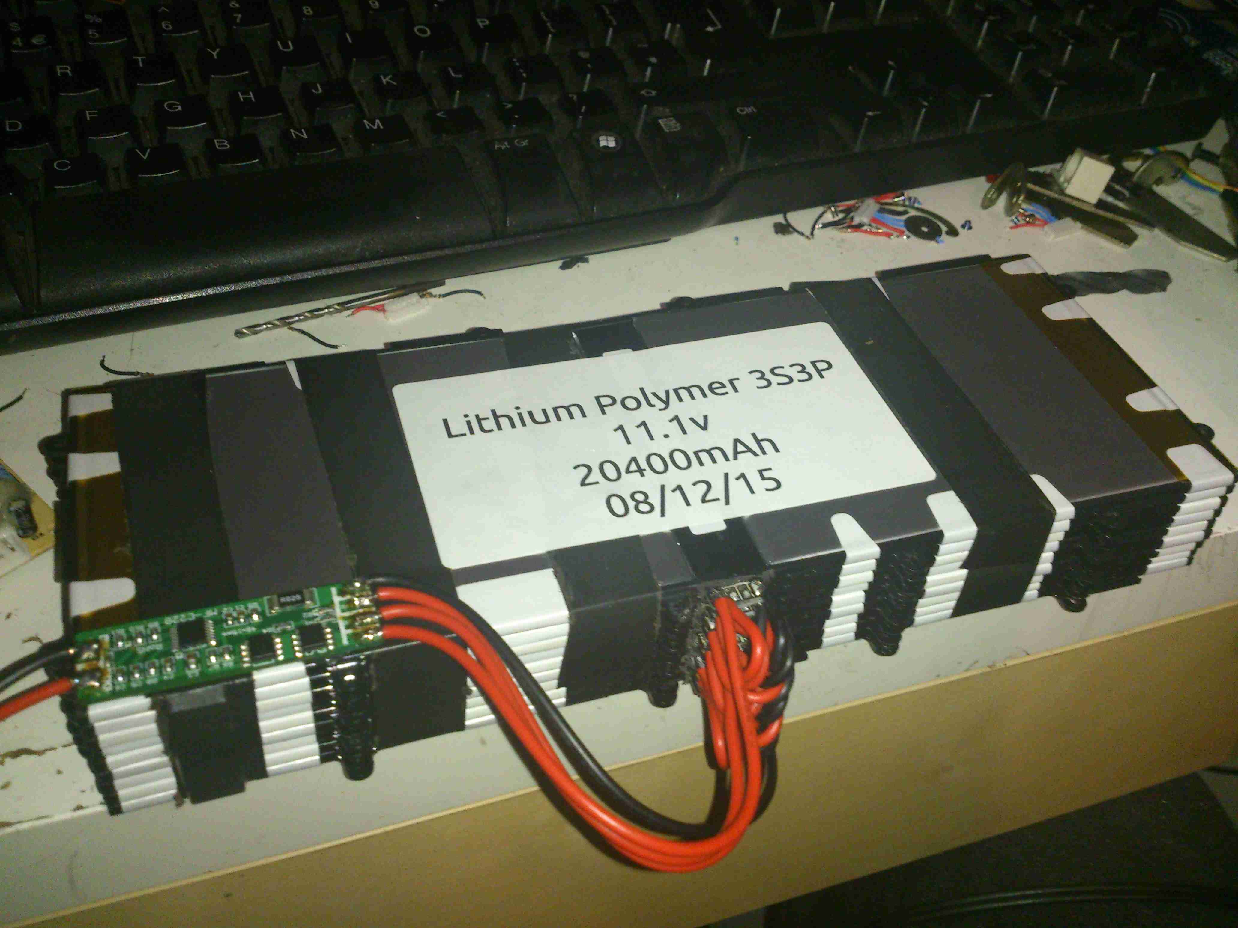
In the past, I’ve used RC type LiPo packs for my mobile power requirements, but these tend to be a bit bulky, since they’re designed for very high discharge current capability – powering large motors in models is a heavy job.
I recently came across some Samsung Galaxy Tab 10.1 battery packs on eBay very cheaply, at £2.95 a piece. For this price I get 6800mAh of capacity at 4.2v, for my 12v requirements, 3 packs must be connected in series, for a total output of 12.6v fully charged.
For an initial pack, I got 9 of these units, to be connected in 3 sets of 3 to make 20Ah total capacity.There are no control electronics built into these batteries – it’s simply a pair of 3400mAh cells connected in parallel through internal polyfuses, and an ID EEPROM for the Tab to identify the battery.
This means I can just bring the cell connections together with the original PCB, without having to mess with the welded cell tabs.
Battery Pack
Here’s the pack with it’s cell connections finished & a lithium BCM connected. This chemistry requires close control of voltages to remain stable, and with a pack this large, a thermal runaway would be catastrophic.
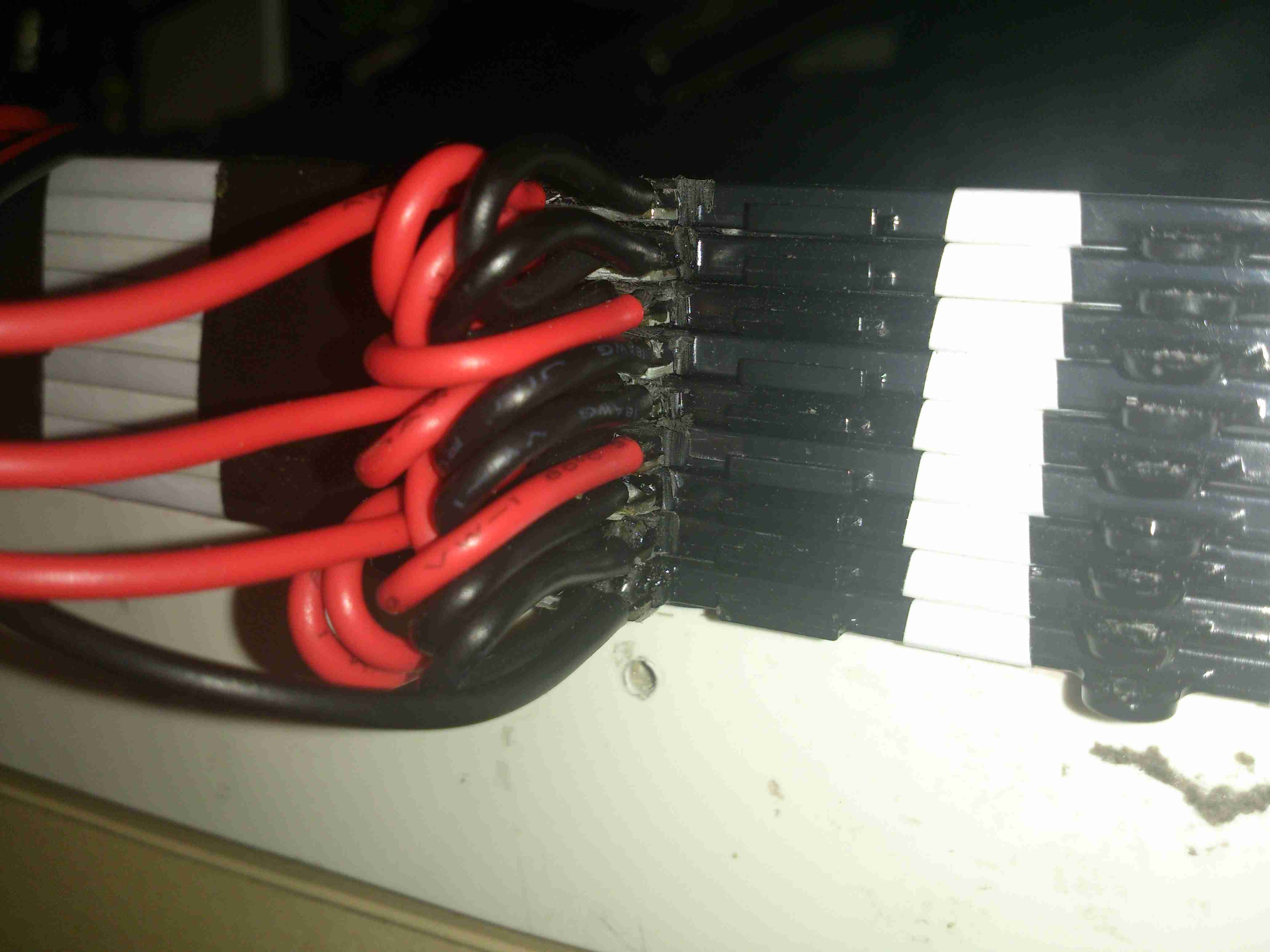
Cell Links
The OEM battery connector has been removed, and my series-parallel cell connections are soldered on, with extra lead-outs for balancing the pack. This was the most time-consuming part of the build.
If all goes well with the life of this pack for utility use, I’ll be building another 5 of these, for a total capacity of 120Ah. This will be extremely useful for portable use, as the weight is about half that of an equivalent lead-acid.
Tip Jar
If you’ve found my content useful, please consider leaving a donation by clicking the Tip Jar below!
All collected funds go towards new content & the costs of keeping the server online.