Posted on Leave a comment

eBay Green Laser Pen – Unexpected High Power

Green Laser Pointer
Green Laser Pointer

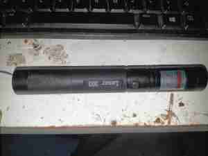
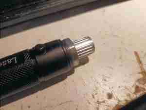
Here’s a cheapo 532nm green laser pointer courtesy of eBay, this one rolled in at £7, with 18650 cell & charger included. Advertised at 1mW, I was immediately suspicious of the output power since this unit quite easily causes skin burns.

Laser Warning Label
Laser Warning Label

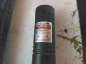
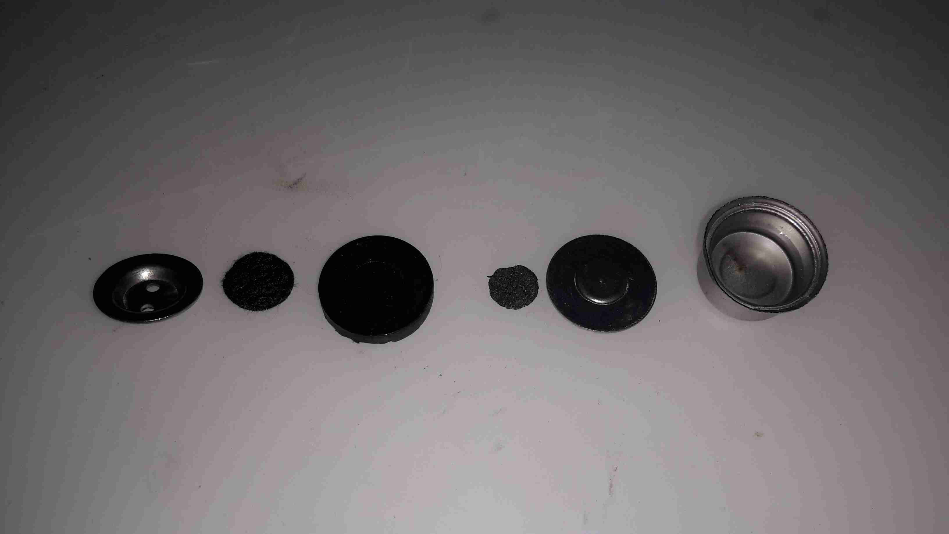
The warning label rates this laser at Class III, with an output power of <1000mW. Massively higher than the 1mW advertised. The end cap is split into two parts that are threaded – the first one is a starfield effect diffraction grating, while the second one moves the final optic to focus the beam.

Starfield Diffraction Grating

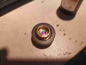
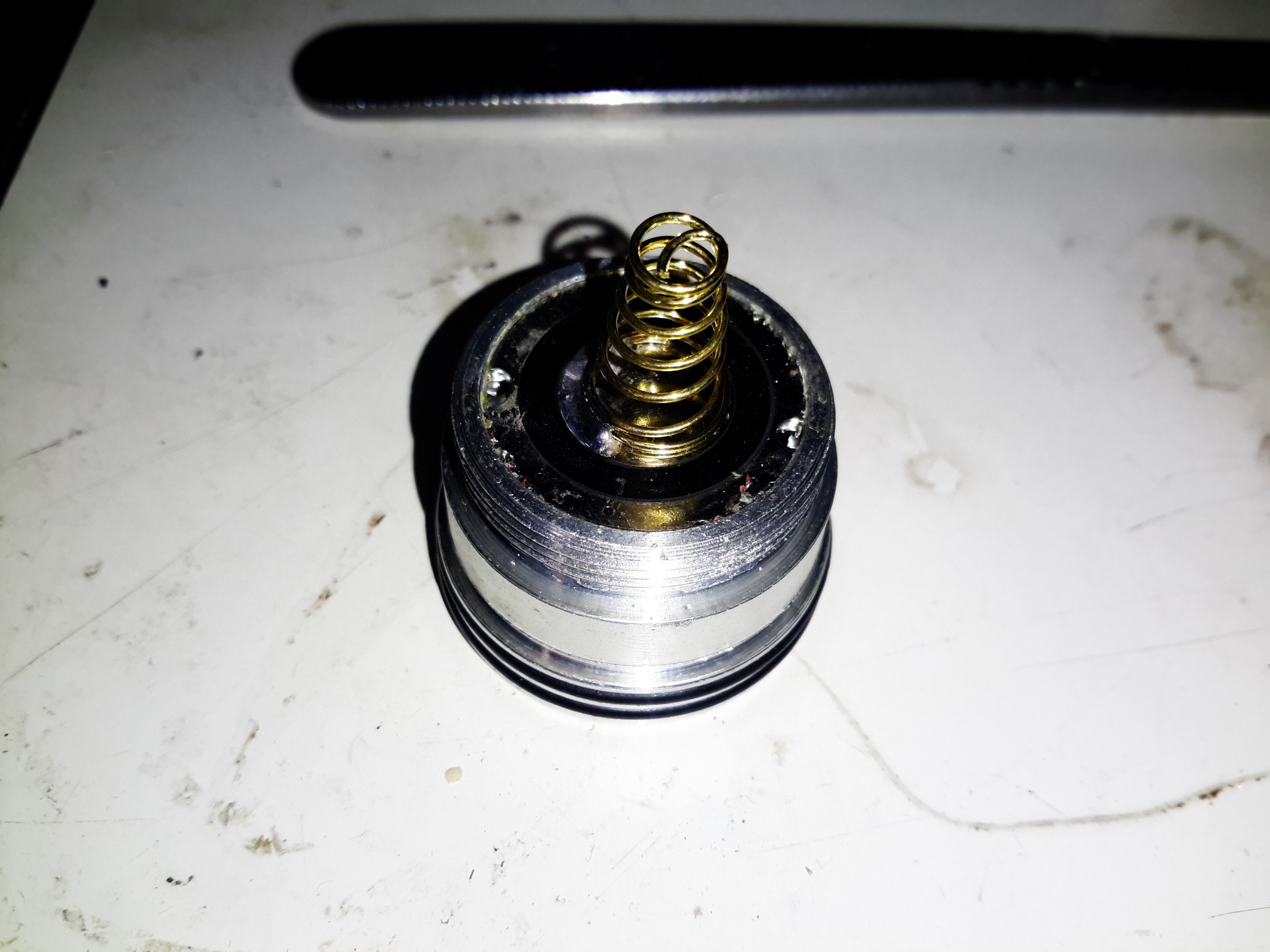
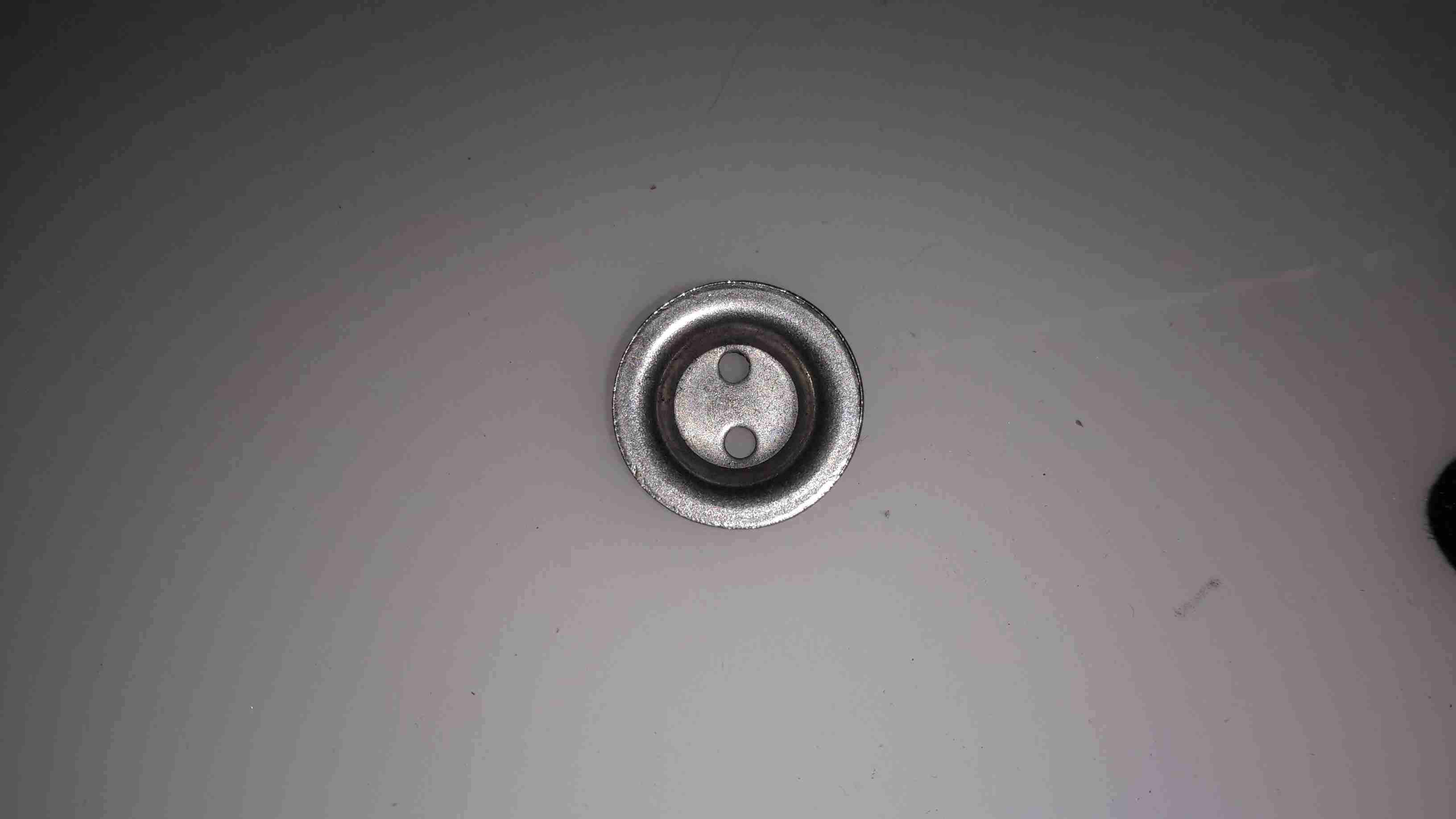
The starfield gratings are mounted inside a brass ferrule, which can be rotated to alter the effect without unscrewing from the main body.

Optics Removed
Optics Removed

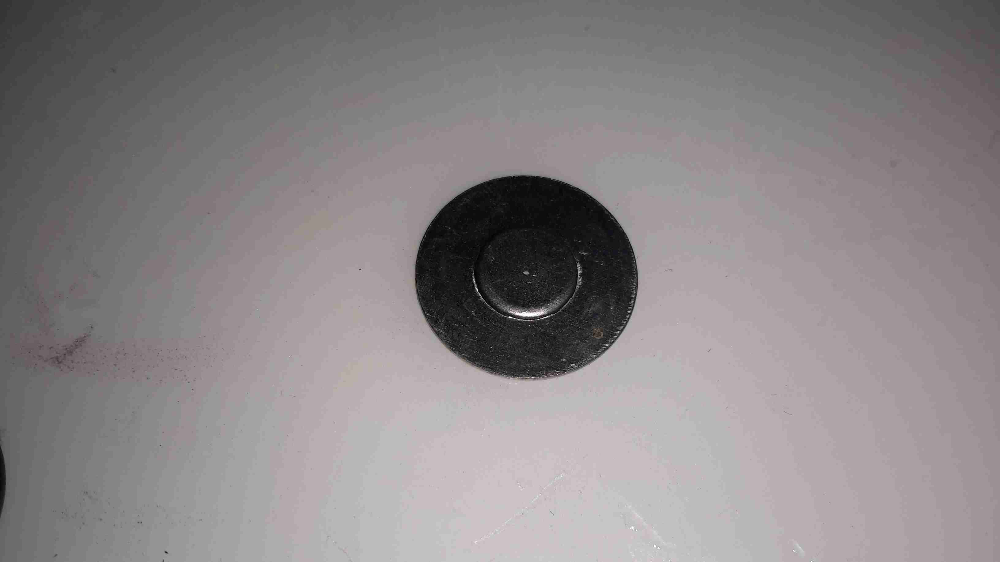
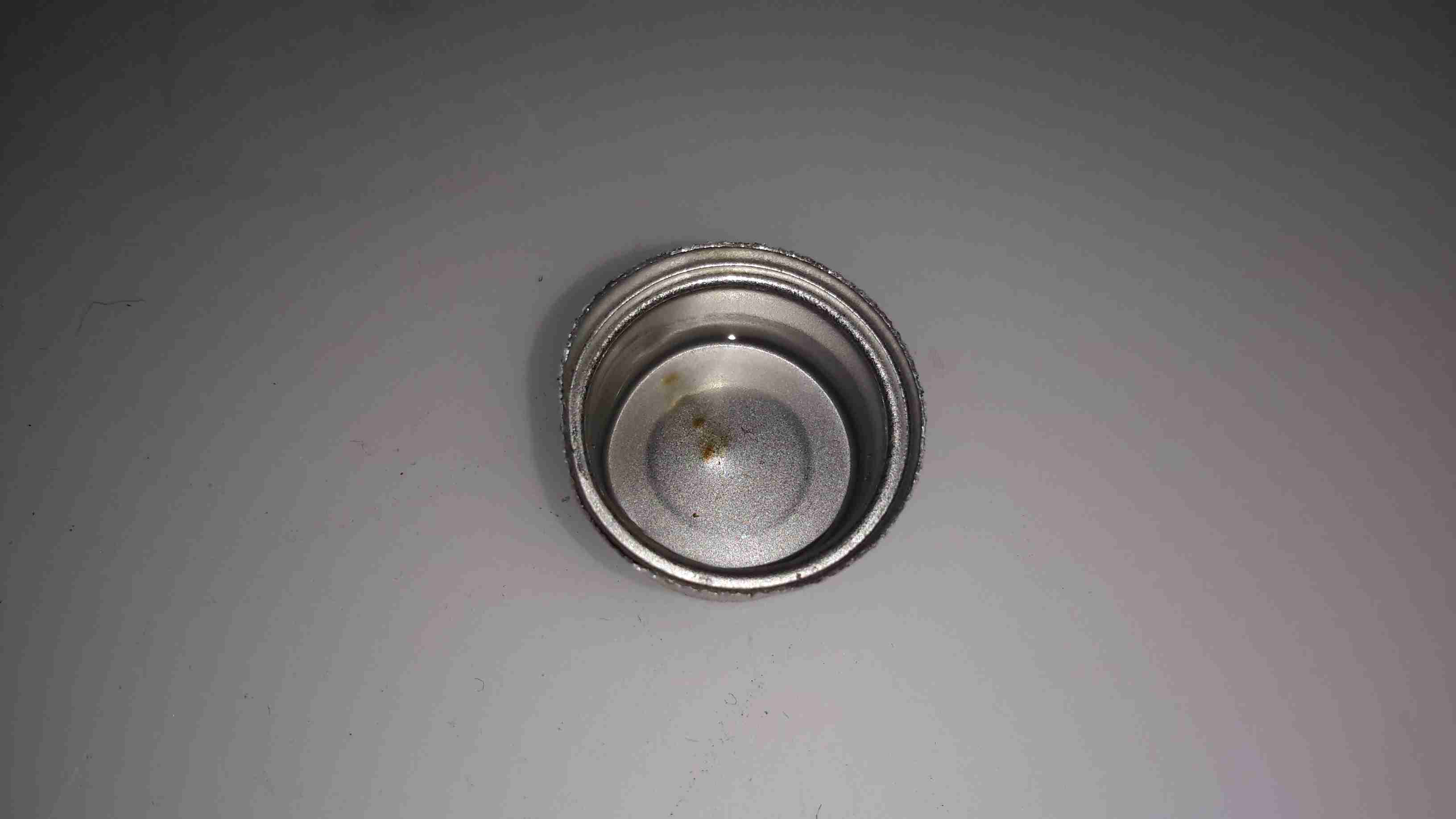
Removing the output optic barrel reveals the end of the DPSS laser module, which appears to be well glued in. The aluminium cylinder doesn’t appear to have any other purpose other than to protect the laser output end.

KTP Crystal & Lens
KTP Crystal & Lens

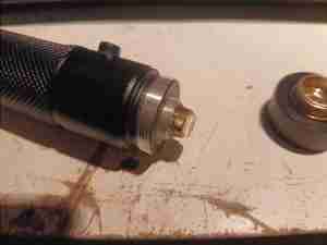
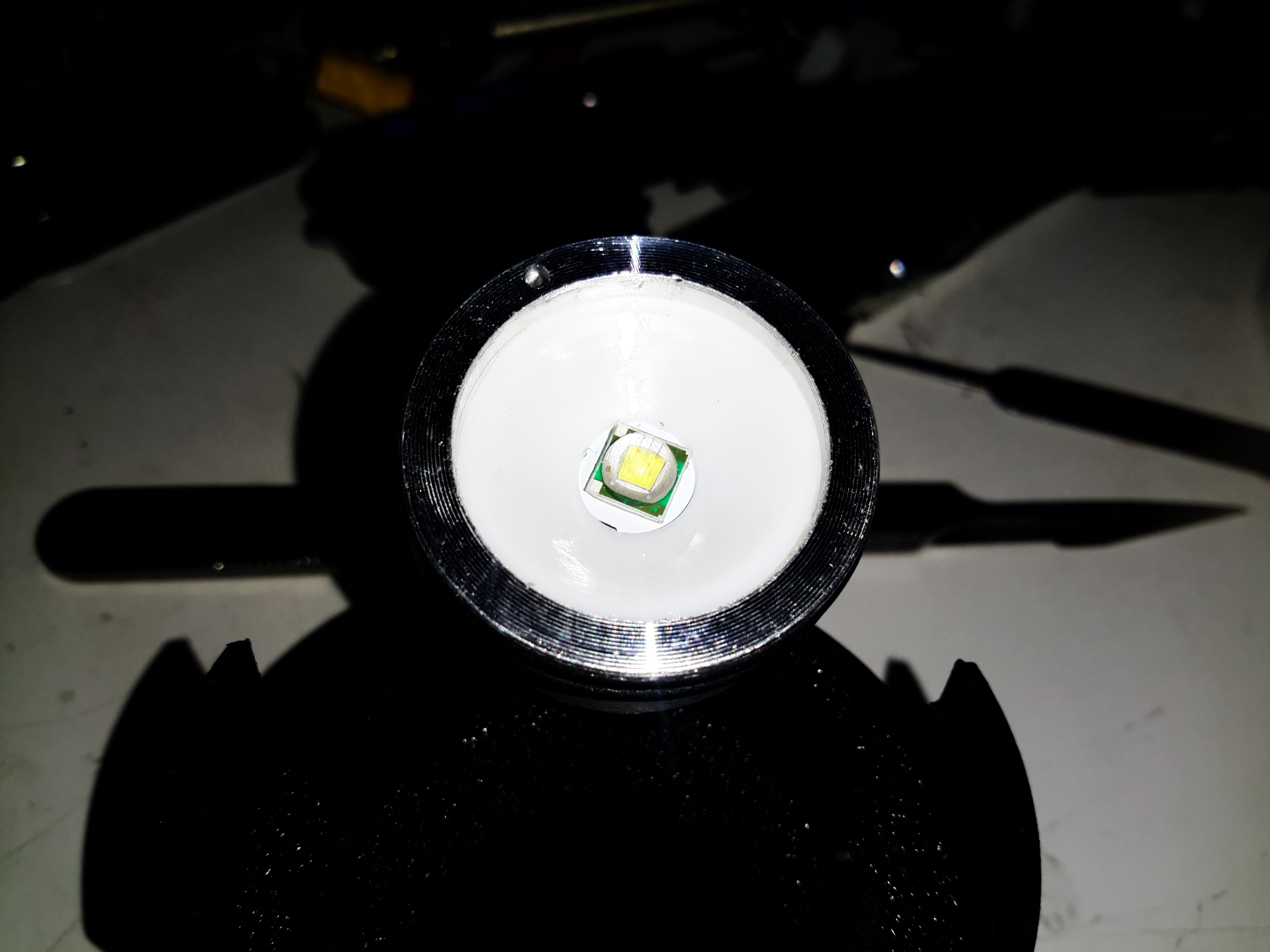
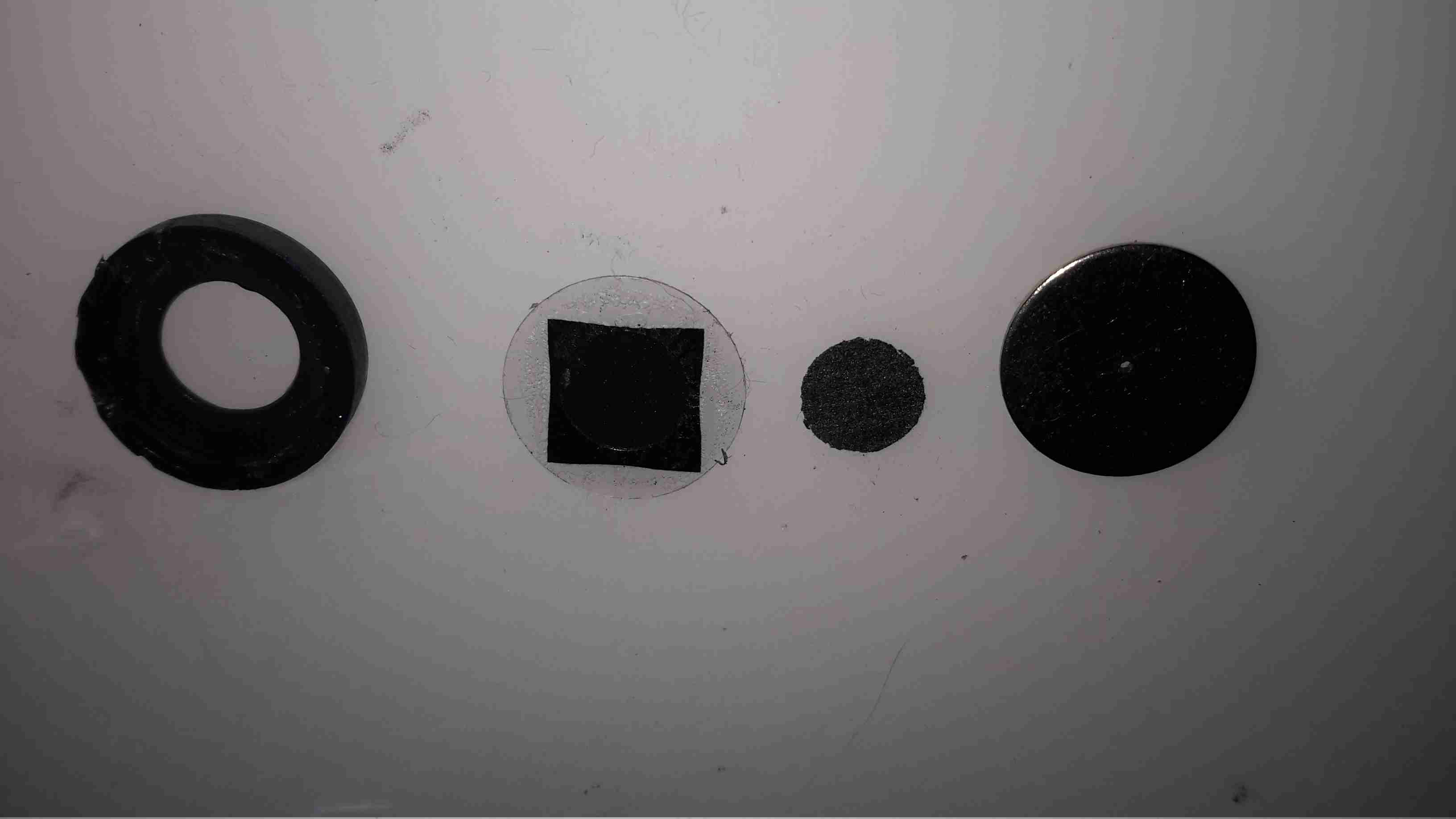
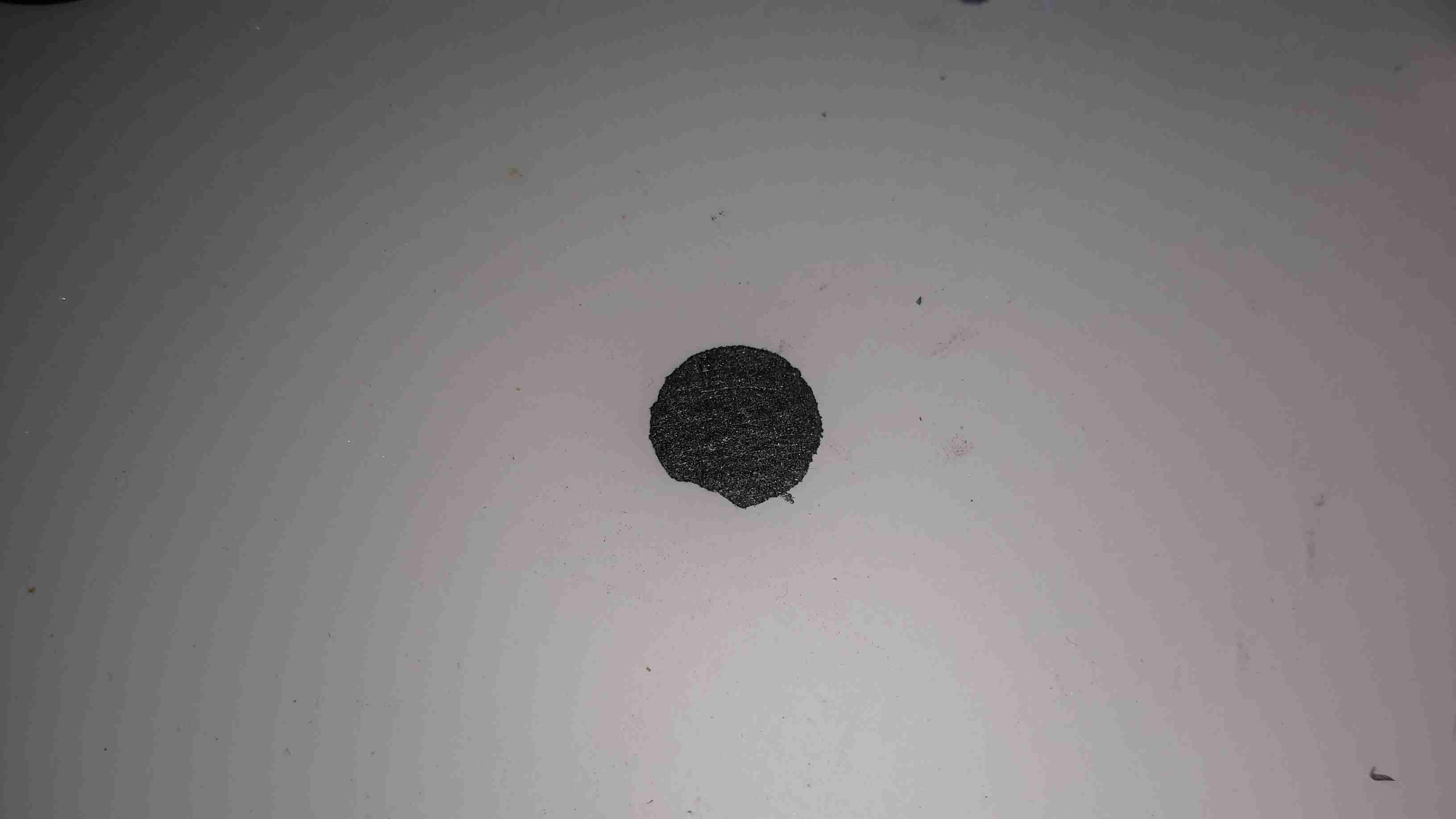
Unscrewing the cylinder reveals the glued holder containing the KTP crystal, and the first output optic. The beam from this alone is very divergent, expanding to ~100mm over a meter or so. The beam right at the optic though is highly focussed & is quite capable of cutting through black electrician’s tape.
There’s also no IR filter anywhere in the optical path – so there is going to be a high power 808nm/1064nm component to the beam since these wavelengths are used in the DPSS process. Since these components are totally invisible, the risk for eye damage is higher due to lack of a blink reflex.

Power Reading
Power Reading

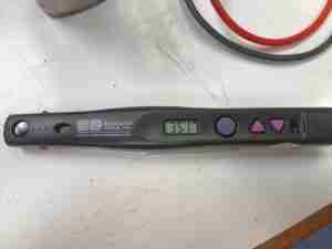
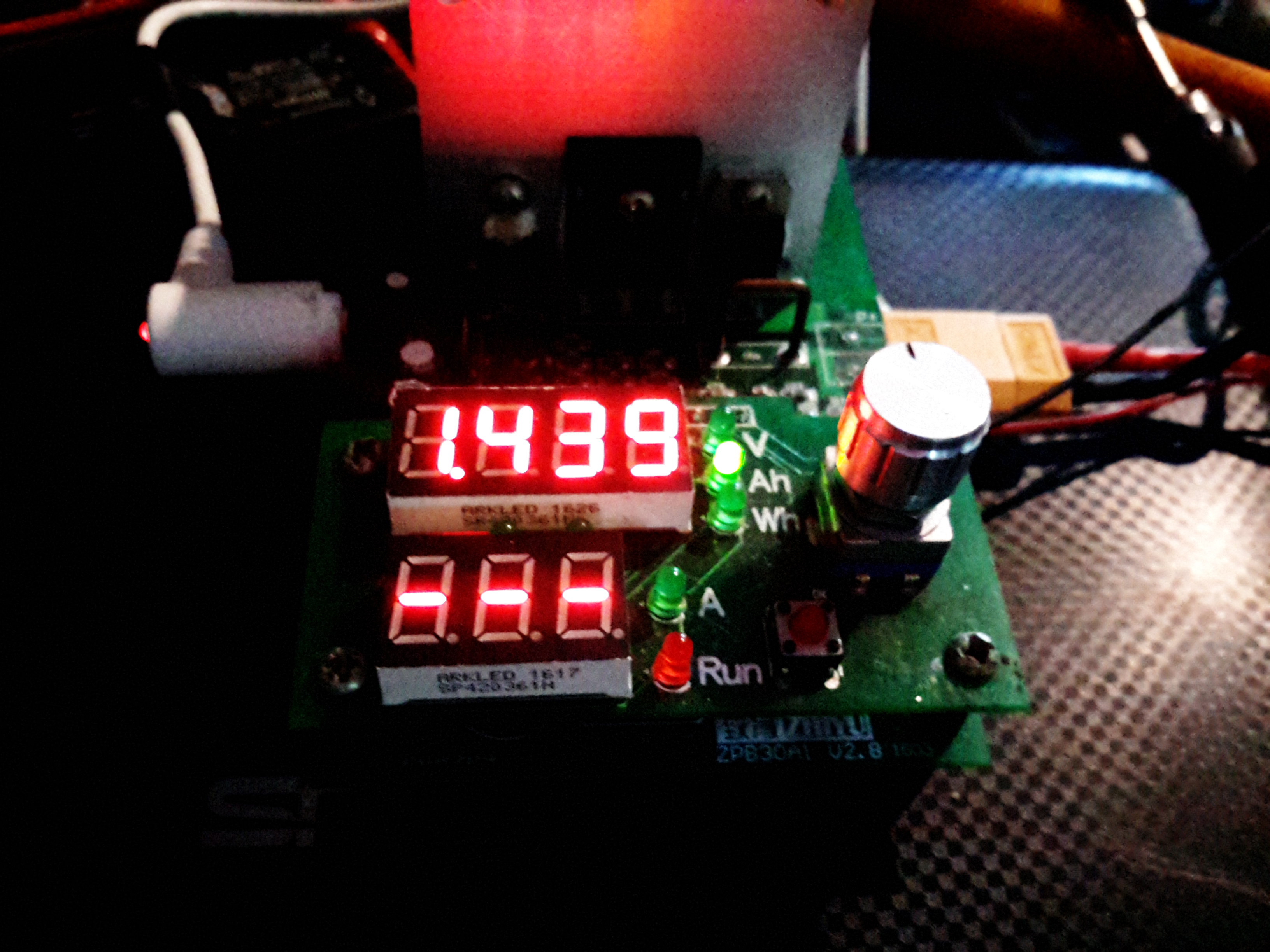
On to the power reading… 351mW of output at 532nm. So quite a bit more than the advertised spec then, but lower than the warning label states. This puts this unit into Class IIIB.

Cell Capacity
Cell Capacity

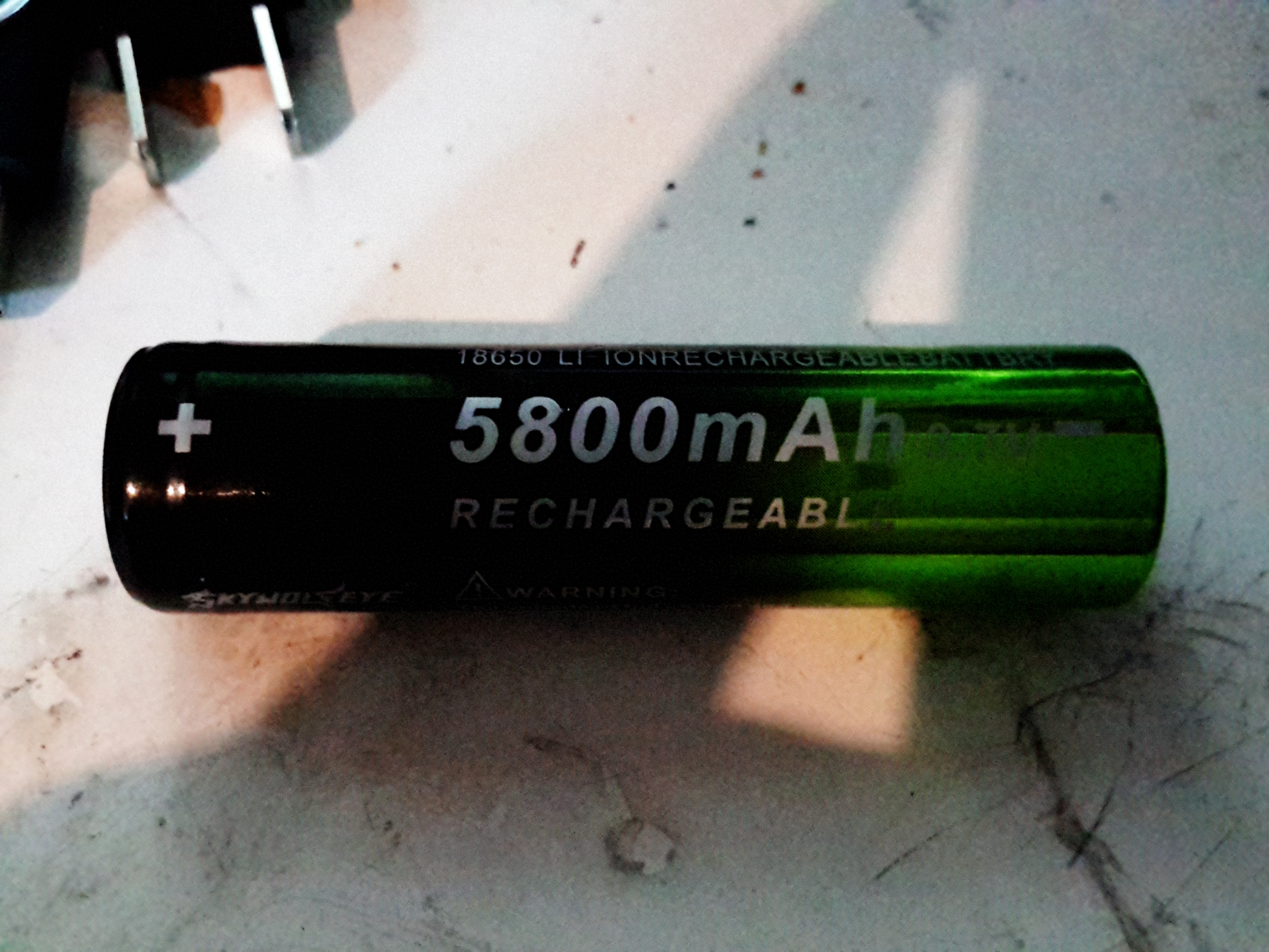
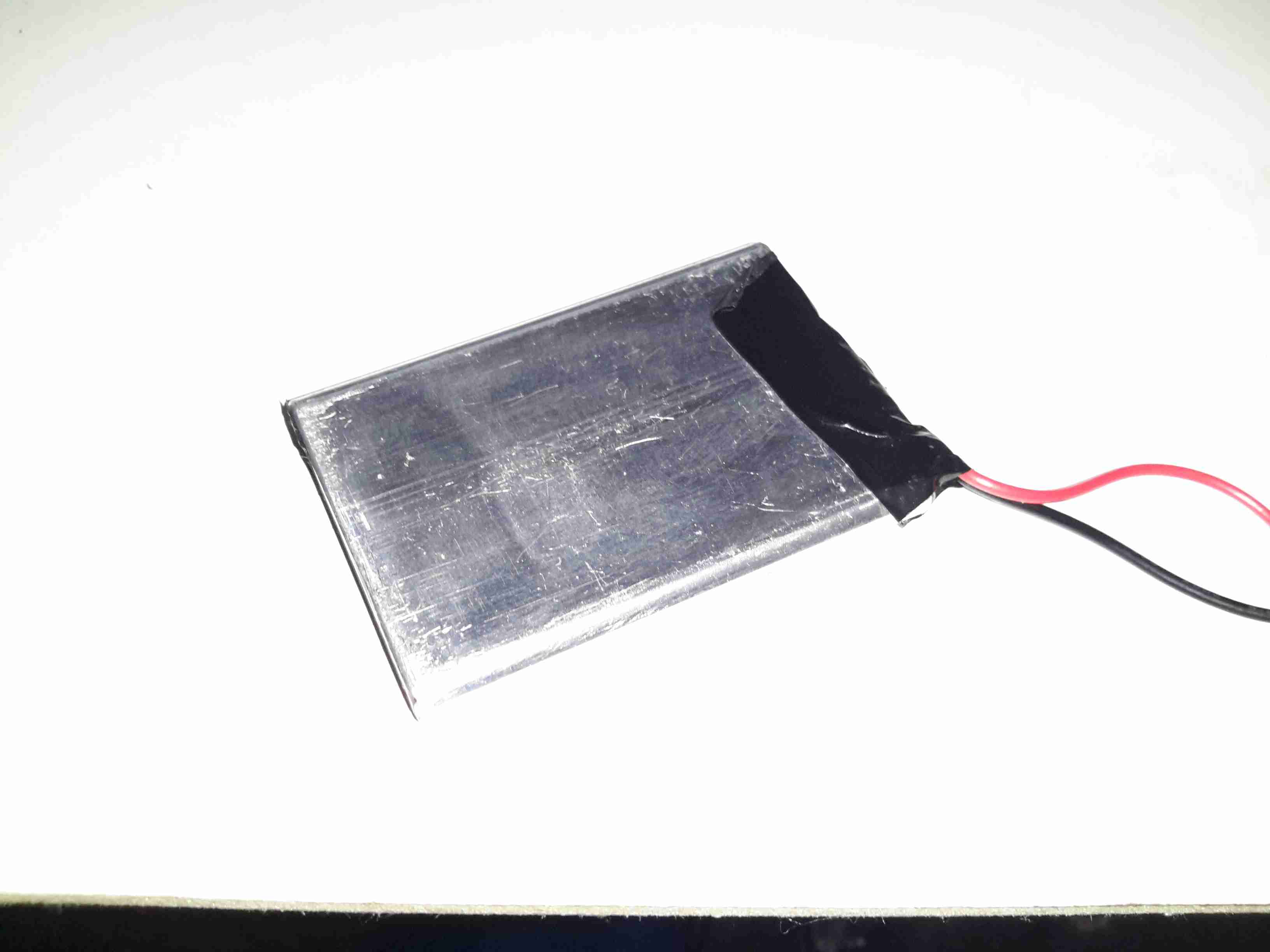
From a full charge, down to 2.8v, the “4000mAh” cell provided with this unit managed a pitiful 1128mAh. I knew from the second I got this cell that it would be a fake, since decent 18650 lithium-ion cells cost about the same as this whole package.

Fake Cell
Fake Cell

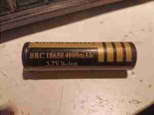
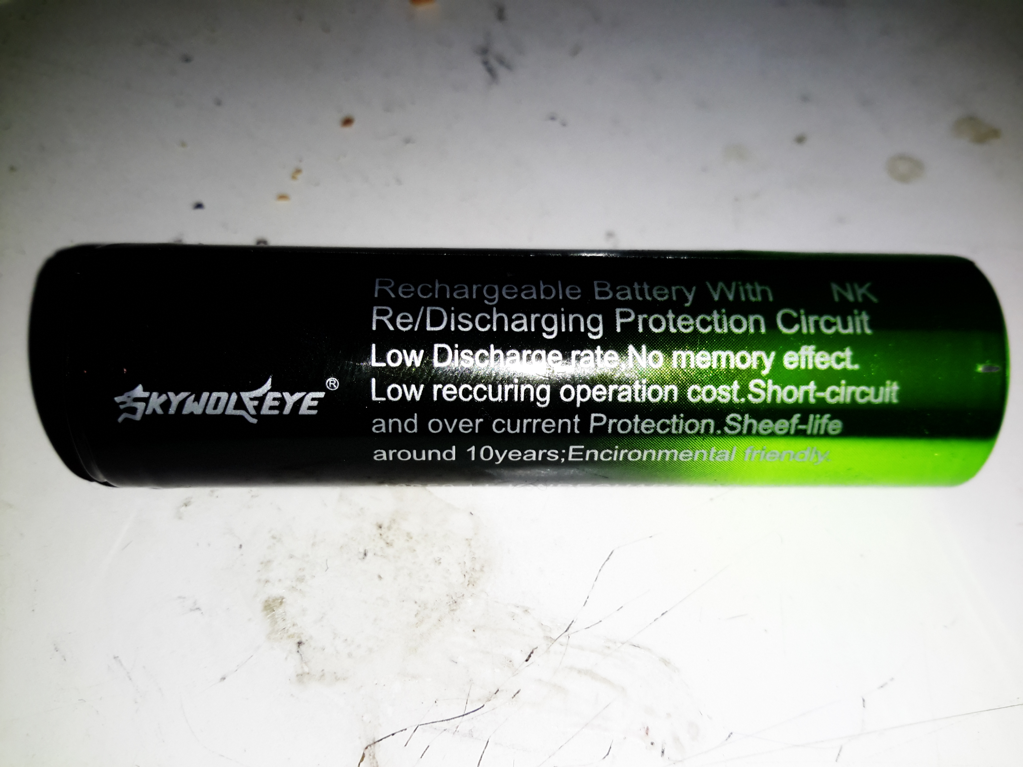
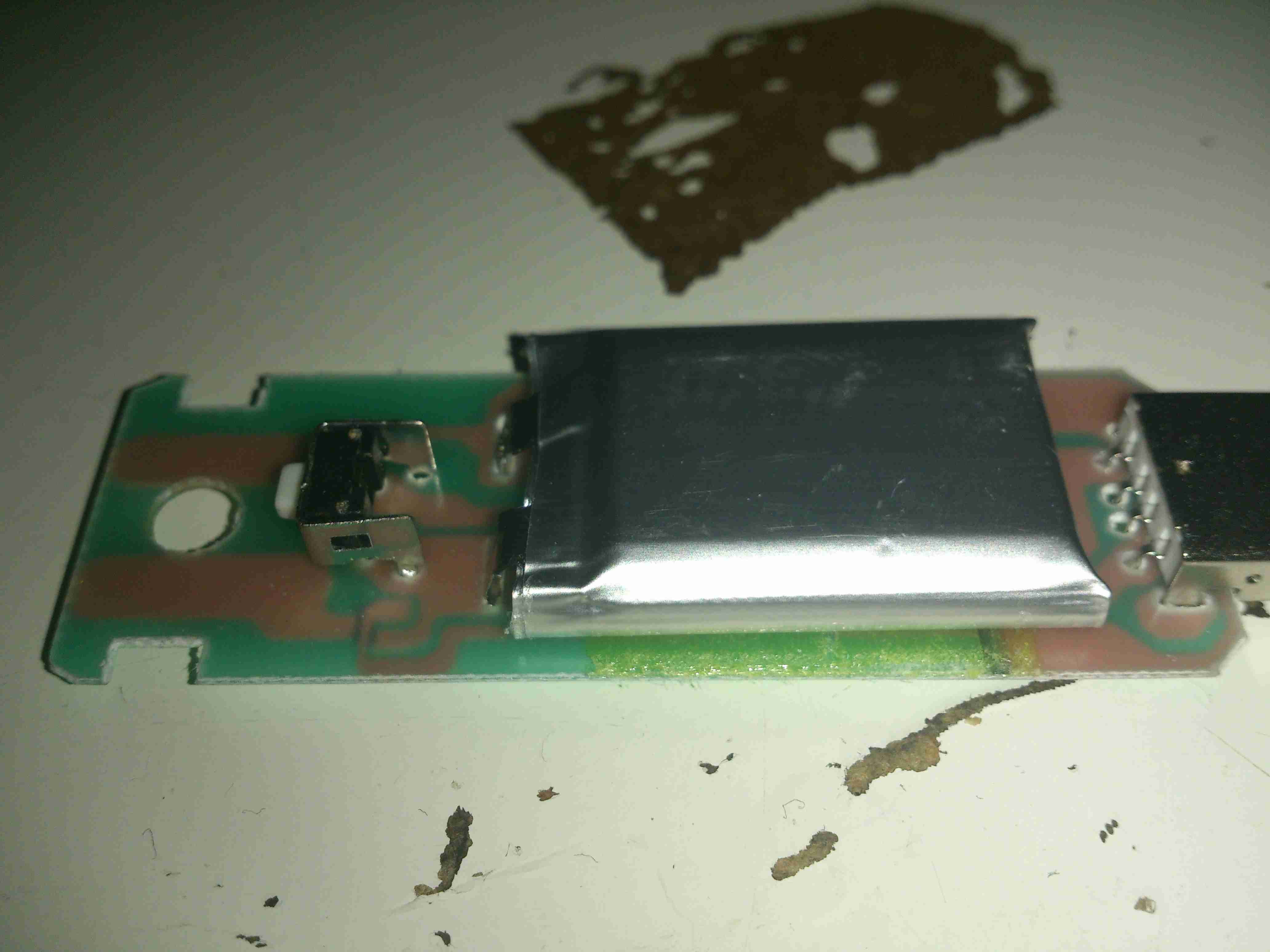
This cell claims a 4000mAh capacity, and built in protection circuit. Let’s dig under the sleeve…

Nope. No protection circuit here. It’s easy to tell anyway – protected cells are longer, and usually the strap buggering off to the other end of the cell is visible through the sleeve. There is a dual-layer sleeve though, of clear PVC under the BRC branded one. No other markings on the cell at all, and it’s suspiciously light in weight.

Posted on Leave a comment

SkyWolfEye Cree XM-L 18650 Torch

It’s been a bit quiet around here for a couple of weeks, as it’s the run-up to Download Festival here in the UK, so I’ve been busy sorting everything out for that. Just in time a new order has come in!

Due to a small accident with the old Maplin torch from a while back, (turns out they don’t float when dropped in the canal – ooops), a new one was sourced. Maplin is very expensive considering the imported crap they peddle these days, so I figured eBay would be the best bet for cheap imported crap 😉 This unit came with a few accessories, so I’ll start with the torch itself.

18650 Torch
18650 Torch

This is an aluminium unit, and does feel quite well built for the price, but it does have a few disappointing things. The lens assembly at the front is movable so focus the beam – the range goes from wide flood to a very small spot.

Power Switch
Power Switch

The power switch on this torch is at the back on the cap, covered by this obscenely brightly coloured cap.

Lens Assembly
Lens Assembly

The lens is a simple plastic moulding, but it produces a nice wide beam.

Enthusiastic Numbers

On to the battery supplied – this claims to be a 5.8Ah 18650 cell, which as far as I’m aware do not exist. I’m always dubious of lithium-ion cells from eBay, the Chinese seem to be well into a race to put the biggest numbers that will fit on the label. (I’ve even seen a USB powerbank claming to have 100Ah of capacity!). The largest capacity cells I have at present are LG HG2 18650s, and those are only rated at 3Ah a piece. They’re also relatively expensive.

Label
Label

The manufacturer couldn’t even get the label spelling correct! Although they do apparently have a 10 year “sheef” life. Never seen that from an 18650 either. They tend to discharge on their own if left unused in about 12 months. I wouldn’t like to think of what the self-discharge rate of these dodgy things is, and I don’t intend to keep them to find out either!

Battery Capacity
Battery Capacity

After a quick blast on the charger to top them up, on the discharge tester they go! This test was conducted at 1A, and this now shows the true capacity of 1.439Ah, which is honestly better than I was expecting. Already having high quality cells I wasn’t fussed about this aspect of the purchase, I knew these cells would end up in the bin.

LED Module
LED Module

Unscrewing the lens housing at the front gives access to the LED module – this is a Cree XM-L die in here, although it might not be a genuine Cree (or possibly a factory reject). The LED housing is aluminium, the LED uses this as a heatsink.

Positive Contact Spring

Nothing special about the back of the module after it’s been unscrewed from the barrel. There’s a couple of O-Rings to seal the sliding lens assembly, I lubricated these with some silicone grease to try & make the housing somewhat splashproof.

Control PCB
Control PCB

The control PCB is pulled out of the housing to reveal the circuitry. The LED is controlled by a SOT-23 mode IC & a SO-8 MOSFET. There’s nothing complex about the LED current limiting, just a bunch of SMD resistors in parallel to set the limit. This torch, like 99% of Chinese import torches from eBay, has a multi-mode IC with SOS & strobe. I don’t need this crap, and it’s easily bypassed.

Modifications
Modifications

Here I’ve desoldered the MOSFET from the board & jumped across it’s drain & source connections, converting the torch to simple ON/OFF control.

Posted on Leave a comment

eBay Special – LED Disco Light With Built In MP3 Player

Here’s an eBay oddity – it’s got the same light & lens mechanism as the cheap “disco light” style bulbs on eBay, but this one is battery powered & has a built in MP3 player.

MP3 Disco Light
MP3 Disco Light

This device simply oozes cheapness. The large 4″ plastic dome lens sits on the top above the cheap plastic moulding as a base, which also contains the MP3 player speaker.

Controls
Controls

There are few controls on this player, the volume buttons are combined with the skip track buttons, a long press operates the volume control, while a short press skips the tracks. Several options for getting this thing to play music are provided:

  • Bluetooth – Allows connection from any device for bluetooth audio
  • USB – Plugging in a USB flash drive with MP3 files
  • SD Card – Very similar to the USB flash drive option, just a FAT32 formatted card with MP3 files
  • Aux – There’s no 3.5mm jack on this unit for an audio input, instead a “special” USB cable is supplied that is both used to charge the built in battery & feed an audio signal. This is possible since the data lines on the port aren’t used. But it’s certainly out of the ordinary.
Top Removed
Top Removed

The top comes off with the removal of a single screw in the centre of the lens. The shaft in the centre that holds the lens is attached to a small gear motor under the LED PCB. There’s 6 LEDs on the board, to form an RGB array. Surprisingly for a very small battery powered unit these are bright to the point of being utterly offensive.

Mainboard
Mainboard

Here’s the mainboard removed from the plastic base. There’s not much to this device, even with all the options it has. The power switch is on the left, followed by the Mini-B USB charging port & aux audio input. The USB A port for a flash drive is next, finishing with the µSD slot. I’m not sure what the red wire is for on the left, it connects to one of the pins on the USB port & then goes nowhere.

Audio Amplifier
Audio Amplifier

The audio amplifier is a YX8002D, I couldn’t find a datasheet for this, but it’s probably Class D.

Main Chipset
Main Chipset

Finally there’s the main IC, which is an AC1542D88038. I’ve not been able to find any data on this part either, it’s either a dedicated MP3 player with Bluetooth radio built in, or an MCU of some kind.The RF antenna for the Bluetooth mode is at the top of the board.
Just behind the power switch is a SOT23-6 component, which should be the charger for the built in Lithium Ion cell.

Lithium Ion Cell
Lithium Ion Cell

The cell itself is a prismatic type rated in the instructions at 600mAh, however my 1C discharge test gave a reading of 820mAh, which is unusual for anything Li-Ion based that comes from eBay 😉
There is cell protection provided, it’s under the black tape on the end, nothing special here.

The main issue so far with this little player is the utterly abysmal battery life – at full volume playing MP3s from a SD card, the unit’s current draw is 600mA, with the seizure & blindness-inducing LEDs added on top, the draw goes up to about 1200mA. The built in charger is also not able to keep up with running the player while charging. This in all only gives a battery life of about 20 minutes, which really limits the usability of the player.

Posted on Leave a comment

Chinese CO Meter – The Sensor Cell

As the CO meter I bought on eBay didn’t register anything whatsoever, I decided I’d hack the sensor itself apart to make sure it wasn’t just an empty steel can. It turns out that it’s not just an empty can, but there are some reasons why the thing doesn’t work 😉

Cell Disassembled
Cell Disassembled

The cell was crimped together under the yellow shrinkwrap, but that’s nothing my aviation snips couldn’t take care of. The photo above shows the components from inside.

End Cap
End Cap

The endcap is just a steel pressing, nothing special here.

Filter
Filter

Also pretty standard is the inlet filter over the tiny hole in the next plate, even though it’s a lot more porous that I’ve seen before in other sensors.

Working Electrode Components

Next up is the working electrode assembly, this also forms the seal on the can when it’s crimped, along with insulating it from the counter electrode & external can. The small disc third from left is supposed to be the electrode, which in these cells should be loaded with Platinum. Considering where else they’ve skimped in this unit, I’ll be very surprised if it’s anything except graphite.

Counter Electrode
Counter Electrode

Next up is the counter electrode, which is identical to the first, working electrode. Again I doubt there’s any precious metals in here.

Backplate
Backplate

Another steel backplate finishes off the cell itself, and keeps most of the liquid out, just making sure everything stays moist.

Rear Can & Reservoir

Finally, the rear of the cell holds the reservoir of liquid electrolyte. This is supposed to be Sulphuric Acid, but yet again they’ve skimped on the cost, and it’s just WATER.

It’s now not surprising that it wouldn’t give me any readings, this cell never would have worked correctly, if at all, without the correct electrolyte. These cheap alarms are dangerous, as people will trust it to alert them to high CO levels, when in fact it’s nothing more than a fancy flashing LED with an LCD display.

Ironically enough, when I connected a real electrochemical CO detector cell to the circuit from the alarm, it started working, detecting CO given off from a burning Butane lighter. It wouldn’t be calibrated, but it proves everything electronic is there & operational. It’s not surprising that the corner cut in this instance is on the sensor cell, as they contain precious metals & require careful manufacturing it’s where the cost lies with these alarms.

Posted on Leave a comment

No-Brand eBay Carbon Monoxide Detector

Chinese CO Alarm
Chinese CO Alarm

I was looking around eBay for decent deals on a branded CO alarm, and came across these for next to no money, so I thought I’d grab one just to see how bad they could be.

Alarm Opened
Alarm Opened

Popping the casing open shows the very small circuit board inside, with the CO sensor cell on the right. I can’t find any manufacturer information on this cell, nor can I find a photo of anything similar on the intertubes, so no specifications there. The other parts are pretty standard, a Piezo sounder & it’s associated step-up transformer to increase the loudness.

Sensor Closeup
Sensor Closeup

The sensor cell has the usual opening in the end to allow entry of gas.

Main PCB
Main PCB

The other side of the board doesn’t reveal much, just an LCD, a couple of LEDs, a pair of transistors, Op-Amp for the sensor & a main microcontroller.

MCU
MCU

The microcontroller isn’t marked unfortunately. It’s not had the number scrubbed off, it’s just never been laser marked with a part number. Above the micro is a SOT-23 LM321 low-power Op-Amp which does the signal conditioning for the CO sensor.


I tried to make this alarm trigger with the exhaust from the Eberspacher heater, which on a well-made branded alarm registered a reading of 154ppm after a few minutes. In the case of this alarm though, I couldn’t make it trigger at all, no matter how long I exposed it to hydrocarbon exhaust gases. I won’t be trusting this one then!

Nothing quite like a piece of safety equipment that doesn’t work correctly from new!

Posted on 2 Comments

Maplin 600W “Modified Sine” Power Inverter

Maplin 600W Inverter

I’m no fan of power inverters. In my experience they’re horrifically inefficient, have power appetites that make engine starter motors look like electric toothbrushes & reduce the life expectancy of lead-acid batteries to no more than a few days.
However I have decided to do a little analysis on a cheapo “600W” model that Maplin Electronics sells.

Cover Removed
Cover Removed

After a serious amount of metallic abuse, the bottom cover eventually came off. The sheet of steel used to close the bottom of the aluminium extrusion was wedged into place with what was probably a 10 ton hydraulic press.
As can be seen from the PCB, there’s no massive 50Hz power transformer, but a pair of high frequency switching transformers. Obviously this is to lighten the weight & the cost of the magnetics, but it does nothing for the quality of the AC output waveform.

DC Input End
DC Input End

The 12v DC from the battery comes in on very heavy 8-gauge cables, this device is fused at 75A!

DC Fuses
DC Fuses

Here’s the fusing arrangement on the DC input stage, just 3 standard blade-type automotive fuses. Interestingly, these are very difficult to get at without a large hammer & some swearing, so I imagine if the user manages to blow these Maplin just expect the device to be thrown out.

Input DC-DC Switching MOSFETs

On the input side, the DC is switched into the pair of transformers to create a bipolar high voltage DC supply.

High Voltage Rectifiers

The large rectifier diodes on the outputs of the transformers feed into the 400v 100µF smoothing capacitors.
As mains AC is obviously a bipolar waveform, I’m guessing this is generating a ±150v DC supply.

Output MOSFETs
Output MOSFETs

After the high voltage is rectified & smoothed, it’s switched through 4 more MOSFETs on the other side of the PCB to create the main AC output.

The label states this is a modified-sine output, so I’d expect something on the scope that looks like this:

Inverter Waveforms
Inverter Waveforms

Modified-sine doesn’t look as bad as just a pure square output, but I suspect it’s a little hard on inductive loads & rectifiers.

However, after connecting the scope, here’s the actual waveform:

Actual Waveform
Actual Waveform

It’s horrific. It’s not even symmetrical. There isn’t even a true “neutral” either. The same waveform (in antiphase) is on the other mains socket terminal. This gives an RMS output voltage of 284v. Needless to say I didn’t try it under load, as I don’t possess anything I don’t mind destroying. (This is when incandescent lamps are *really* useful. Bloody EU ;)).

About the only thing that it’s accurate at reproducing is the 50Hz output, which it does pretty damn well.

System Microcontroller

As is usual these days, the whole system is controlled via a microcontroller.

Posted on Leave a comment

Electronic Lighter – eBay Freebie

With a recent order from a Chinese seller on eBay, this little gadget was included in the package as a freebie:

Electronic Lighter
Electronic Lighter

I’ve not smoked for a long time, so I’m not too sure what use I’m going to find for this device, but it’s an electronic lighter!

Pyromaniac Mode
Pyromaniac Mode

Pushing the slider forward reveals a red-hot heater, mounted in the plastic (!) frame.

Charging Mode
Charging Mode

Pushing the other way reveals a USB port to charge the internal battery.

Core Removed
Core Removed

A couple of screws releases the end cap from the cover & the entire core unit slides out. Like all Chinese toys it’s made of the cheapest plastic imaginable, not such a good thing when heat is involved.

Heating Element
Heating Element

The element itself is a simple coil of Nichrome wire, crimped to a pair of brass terminals. The base the heater & it’s terminals are mounted to is actually ceramic – the surround though that this ceramic pill clips into is just the same cheap plastic. Luckily, the element only remains on for a few seconds on each button push, there’s no way to keep it on & start an in-pocket fire, as far as I can see.

Main PCB
Main PCB

The main PCB clips out of the back of the core frame, the large pair of tinned pads on the left connect to the heater, the control IC has no numbering of any kind, but considering the behaviour of the device it’s most likely a standard eCig control IC.

LiPo Cell
LiPo Cell

The other side of the board has the USB port on the right, the Lithium Polymer cell in the centre, and the power button on the left. The cell itself also has no marking, but I’m guessing a couple hundred mAh from the physical size.