Posted on 8 Comments

Sterling ProCharge Ultra PCU1210 Teardown & Repair

The Sterling charger we’ve had on board nb Tanya Louise since Feb 2014 has bitten the dust, with 31220 hours on it’s internal clock. Since we’re a liveaboard boat, this charger has had a lot of use while we’re on the mooring during winter, when the solar bank isn’t outputting it’s full rate. First, a bit of a teardown to explore the unit, then onto the repair:
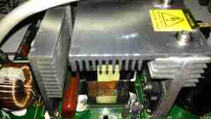

Active PFC Section
Active PFC Section

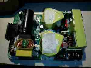
There’s the usual mains input filtering on the left, with the bridge rectifier on it’s heatsink.
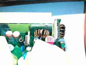
Underneath the centre massive heatsinks is the main transformer (not visible here) & active PFC circuit. The device peeking out from underneath is the huge inductor needed for PFC. It’s associated switching MOSFET is to the right.
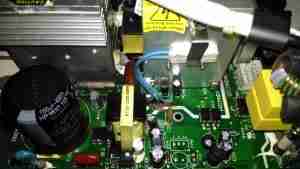
Logic PSU Section
Logic PSU Section

On the other side of the PFC section is the main DC rail filter electrolytic, a 450v 150µF part. Here some evidence of long-term heating can be seen in the adhesive around the base, it’s nearly completely turned black! It’s not a decent brand either, a Chinese CapXon.
The PCB fuse just behind it is in the DC feed to the main switching supply, so the input fuse only protects the filter & Active PFC circuitry. Luckily this fuse didn’t blow during the failure, telling me the fault was earlier in the power chain.
The logic circuits are powered by an independent switching supply in the centre, providing a +5v rail to the microcontroller. The fan header & control components are not populated in this 10A model, but I may end up retrofitting a fan anyway as this unit has always run a little too warm. The entire board is heavily conformal coated on both sides, to help with water resistance associated with being in a marine environment. This has worked well, as there isn’t a single trace of moisture anywhere, only dust from years of use.
There is some thermal protection for the main SMPS switching MOSFETS with the Klixon thermal fuse clipped to the heatsink.
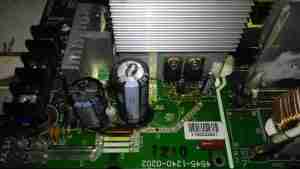
DC Output Section
DC Output Section

The DC output rectifiers are on the large heatsink in the centre, with a small bodge board fitted. Due to the heavy conformal coating on the board I can’t get the ID from this small 8-pin IC, but from the fact that the output rectifiers are in fact IRF1010E MOSFETS, rated at 84A a piece, this is an synchronous rectifier controller.
Oddly, the output filter electrolytics are a mix of Nichicon (nice), and CapXon (shite). A bit of penny pinching here, which if a little naff since these chargers are anything but cheap. (£244.80 at the time of writing).
Hiding just behind the electrolytics is a large choke, and a reverse-polarity protection diode, which is wired crowbar-style. Reversing the polarity here will blow the 15A DC bus fuse instantly, and may destroy this diode if it doesn’t blow quick enough.
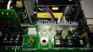
DC Outputs
DC Outputs

Right on the output end are a pair of large Ixys DSSK38 TO220 Dual 20A dual Schottky diodes, isolating the two outputs from each other, a nice margin on these for a 10A charger, since the diodes are paralleled each channel is capable of 40A. This prevents one bank discharging into another & allows the charger logic to monitor the voltages individually. The only issue here is the 400mV drop of these diodes introduce a little bit of inefficiency. To increase current capacity of the PCB, the aluminium heatsink is being used as the main positive busbar. From the sizing of the power components here, I would think that the same PCB & component load is used for all the chargers up to 40A, since both the PFC inductor & main power transformer are massive for a 10A output. There are unpopulated output components on this low-end model, to reduce the cost since they aren’t needed.
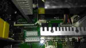
Front Panel Control Connections

A trio of headers connect all the control & sense signals to the front panel PCB, which contains all the control logic. This unit is sensing all output voltages, output current & PSU rail voltages.
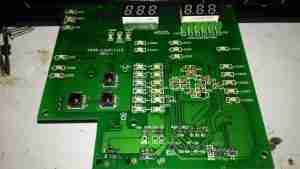
Front Panel LEDs
Front Panel LEDs

The front panel is stuffed with LEDs & 7-segment displays to show the current mode, charging voltage & current. There’s 2 tactile switches for adjustments.
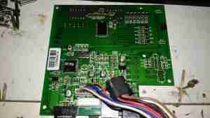
Front Panel Reverse
Front Panel Reverse

The reverse of the board has the main microcontroller – again identifying this is impossible due to the heavy conformal coat. The LEDs are being driven through a 74HC245D CMOS Octal Bus Transceiver.


Now on to the repair! I’m not particularly impressed with only getting 4 years from this unit, they are very expensive as already mentioned, so I would expect a longer lifespan. The input fuse had blown in this case, leaving me with a totally dead charger. A quick multimeter test on the input stage of the unit showed a dead short – the main AC input bridge rectifier has gone short circuit.
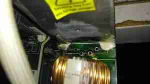
Bridge Rectifier Removed

Here the defective bridge has been desoldered from the board. It’s a KBU1008 10A 800v part. Once this was removed I confirmed there was no longer an input short, on either the AC side or the DC output side to the PFC circuit.
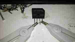
Testing The Rectifier

Time to stick the desoldered bridge on the milliohm meter & see how badly it has failed.
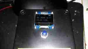
Yep, Definitely Shorted

I’d say 31mΩ would qualify as a short. It’s no wonder the 4A input fuse blew instantly. There is no sign of excessive heat around the rectifier, so I’m not sure why this would have failed, it’s certainly over-rated for the 10A charger.
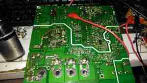
Testing Without Rectifier

Now the defective diode bridge has been removed from the circuit, it’s time to apply some controlled power to see if anything else has failed. For this I used a module from one of my previous teardowns – the inverter from a portable TV.
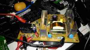
Test Inverter
Test Inverter

This neat little unit outputs 330v DC at a few dozen watts, plenty enough to power up the charger with a small load for testing purposes. The charger does pull the voltage of this converter down significantly, to about 100v, but it still provides just enough to get things going.
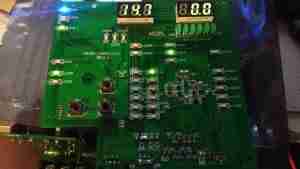
It's Alive!
It’s Alive!

After applying some direct DC power to the input, it’s ALIVE! Certainly makes a change from the usual SMPS failures I come across, where a single component causes a chain reaction that writes off everything.
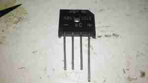
Replacement Rectifier

Unfortunately I couldn’t find the exact same rectifier to replace the shorted one, so I had to go for the KBU1010, which is rated for 1000v instead of 800v, but the Vf rating (Forward Voltage), is the same, so it won’t dissipate any more power.
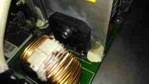
Soldered In
Soldered In

Here’s the new rectifier soldered into place on the PCB & bolted to it’s heatsink, with some decent thermal compound in between.
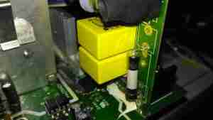
Input Board
Input Board

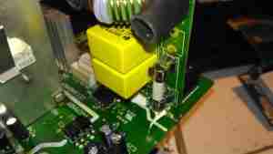
Here is the factory fuse, a soldered in device. I’ll be replacing this with standard clips for 20x5mm fuses to make replacement in the future easier, the required hole pattern in the PCB is already present. Most of the mains input filtering is also on this little daughterboard.
Fuse Replaced
Fuse Replaced

Now the fuse has been replaced with a standard one, which is much more easily replaceable. This fuse shouldn’t blow however, unless another fault develops.
Full Load Test
Full Load Test

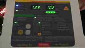
Now everything is back together, a full load test charging a 200Ah 12v battery for a few hours will tell me if the fix is good. This charger won’t be going back into service onboard the boat, it’s being replaced anyway with a new 50A charger, to better suit the larger loads we have now. It won’t be a Sterling though, as they are far too expensive. I’ll report back if anything fails!

Posted on 3 Comments

Anker PowerPort Speed 5 USB Rapid Charger Teardown

Front
Front

Here’s a piece of tech that is growing all the more important in recent times, with devices with huge battery capacities, a quick charger. This unit supports Qualcomm’s Quick Charge 3 standard, where the device being charged can negotiate with the charger for a higher-power link, by increasing the bus voltage past the usual 5v.

Rear
Rear

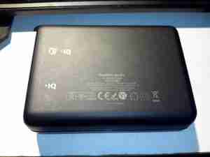
The casing feels rather nice on this unit, sturdy & well designed. All the legends on the case are laser marked, apart from the front side logo which is part of the injection moulding.

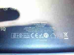
Specifications
Specifications

The power capacity of this charger is pretty impressive, with outputs for QC3 from 3.6-6.5v at 3A, up to 12v 1.5A. Standard USB charging is limited at 4.8A for the other 3 ports.

Ports
Ports

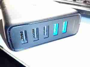
The two of the 5 USB ports are colour coded blue on the QC3 ports. The other 3 are standard 5v ports, the only thing that doesn’t make sense in the ratings is the overall current rating of the 5v supply (4.8A), and the rated current of each of the ports (2.4A) – this is 7.2A total rather than 4.8A.

Top Removed
Top Removed

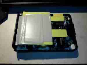
The casing is glued together at the seam, but it gave in to some percussive attack with a screwdriver handle. The inside of this supply is mostly hidden by the large heatspreader on the top.

Main PCB Bottom
Main PCB Bottom

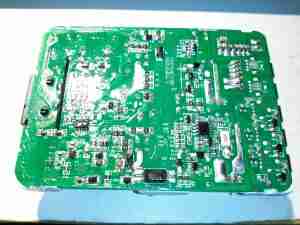
This is a nicely designed board, the creepage distances are at least 8mm between the primary & secondary sides, the bottom also has a conformal coating, with extra silicone around the primary-side switching transistor pins, presumably to decrease the chances of the board flashing over between the close pins.
On the lower 3 USB ports can be seen the 3 SOT-23 USB charge control ICs. These are probably similar to the Texas Instruments TPS2514 controllers, which I’ve experimented with before, however I can’t read the numbers due to the conformal coating. The other semiconductors on this side of the board are part of the voltage feedback circuits for the SMPS. The 5v supply optocoupler is in the centre bottom of the board.

Heatsink Removed
Heatsink Removed

Desoldering the pair of primary side transistors allowed me to easily remove the heatspreader from the supply. There’s thermal pads & grease over everything to get rid of the heat. Here can be seen there are two transformers, forming completely separate supplies for the standard USB side of things & the QC3 side. Measuring the voltages on the main filter capacitors showed me the difference – the QC3 supply is held at 14.2v, and is managed through other circuits further on in the power chain. There’s plenty of mains filtering on the input, as well as common-mode chokes on the DC outputs before they reach the USB ports.

Quick Charge 3 DC-DC Converters

Here’s where the QC3 magic happens, a small DC-DC buck converter for each of the two ports. The data lines are also connected to these modules, so all the control logic is located on these too. The TO-220 device to the left is the main rectifier.

Posted on Leave a comment

eBay Special – LED Disco Light With Built In MP3 Player

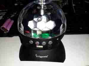
Here’s an eBay oddity – it’s got the same light & lens mechanism as the cheap “disco light” style bulbs on eBay, but this one is battery powered & has a built in MP3 player.

MP3 Disco Light
MP3 Disco Light

This device simply oozes cheapness. The large 4″ plastic dome lens sits on the top above the cheap plastic moulding as a base, which also contains the MP3 player speaker.

Controls
Controls

There are few controls on this player, the volume buttons are combined with the skip track buttons, a long press operates the volume control, while a short press skips the tracks. Several options for getting this thing to play music are provided:

  • Bluetooth – Allows connection from any device for bluetooth audio
  • USB – Plugging in a USB flash drive with MP3 files
  • SD Card – Very similar to the USB flash drive option, just a FAT32 formatted card with MP3 files
  • Aux – There’s no 3.5mm jack on this unit for an audio input, instead a “special” USB cable is supplied that is both used to charge the built in battery & feed an audio signal. This is possible since the data lines on the port aren’t used. But it’s certainly out of the ordinary.
Top Removed
Top Removed

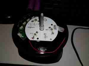
The top comes off with the removal of a single screw in the centre of the lens. The shaft in the centre that holds the lens is attached to a small gear motor under the LED PCB. There’s 6 LEDs on the board, to form an RGB array. Surprisingly for a very small battery powered unit these are bright to the point of being utterly offensive.

Mainboard
Mainboard

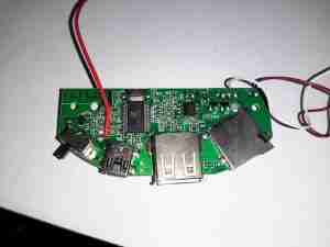
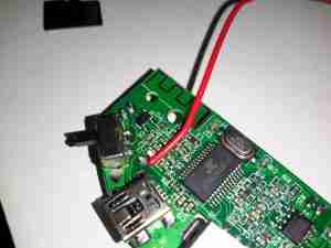
Here’s the mainboard removed from the plastic base. There’s not much to this device, even with all the options it has. The power switch is on the left, followed by the Mini-B USB charging port & aux audio input. The USB A port for a flash drive is next, finishing with the µSD slot. I’m not sure what the red wire is for on the left, it connects to one of the pins on the USB port & then goes nowhere.

Audio Amplifier
Audio Amplifier

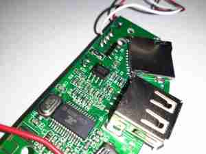
The audio amplifier is a YX8002D, I couldn’t find a datasheet for this, but it’s probably Class D.

Main Chipset
Main Chipset

Finally there’s the main IC, which is an AC1542D88038. I’ve not been able to find any data on this part either, it’s either a dedicated MP3 player with Bluetooth radio built in, or an MCU of some kind.The RF antenna for the Bluetooth mode is at the top of the board.
Just behind the power switch is a SOT23-6 component, which should be the charger for the built in Lithium Ion cell.

Lithium Ion Cell
Lithium Ion Cell

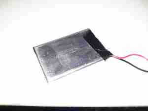
The cell itself is a prismatic type rated in the instructions at 600mAh, however my 1C discharge test gave a reading of 820mAh, which is unusual for anything Li-Ion based that comes from eBay 😉
There is cell protection provided, it’s under the black tape on the end, nothing special here.

The main issue so far with this little player is the utterly abysmal battery life – at full volume playing MP3s from a SD card, the unit’s current draw is 600mA, with the seizure & blindness-inducing LEDs added on top, the draw goes up to about 1200mA. The built in charger is also not able to keep up with running the player while charging. This in all only gives a battery life of about 20 minutes, which really limits the usability of the player.

Posted on Leave a comment

ELuc BLU4 Intelligent Lithium Battery Charger W/Bluetooth

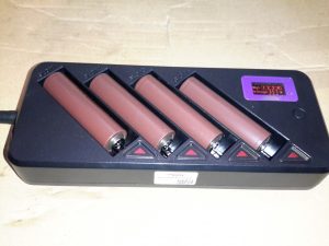
BLU4 Battery Charger

Here’s another battery charger designed for lithium chemistry cells, the BLU4. This charger doesn’t display much on it’s built in LCD, apart from basic cell voltage & charging current limits, as it has a built in Bluetooth module that will link into an Android or iOS app.

Above the charger is operating with 4 brand new cells, at a current of 500mA per cell. If only a pair of cells is being charged, the current can be increased to 1A per cell.

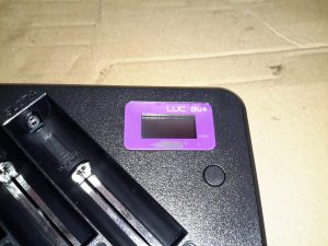
LCD
LCD

Not much in the way of user interface on the charger, a tiny LCD & single button for cycling through the display options.

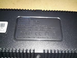
Dataplate
Dataplate

The usual stuff on the data plate, the charger accepts an input of 12v DC at 1A.

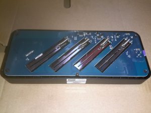
Bottom Cover Removed

Removing the 6 screws on the bottom of the casing allows the board to be seen. Not much on the bottom, the 4 cell negative connections can be seen, with their springs for adjusting for cell length.

MOSFETs
MOSFETs

There’s a couple of P-Channel FETs on the bottom side for the charging circuits, along with some diodes.

Main PCB
Main PCB

The main PCB is easily removed after the springs are unhooked from the terminals. Most of the power circuitry is located on the top side near the power input. There are 4 DC-DC converters on board for stepping the input 12v down to the 4.2v required to charge a lithium cell.

Second Controller
Second Controller

Not entirely sure what this IC is in the bottom corner, as it’s completely unmarked. I’m guessing it’s a microcontroller though.

DC Input Side
DC Input Side

The top left of the board is crammed with the DC-DC converters, all the FETs are in SO8 packages.

DC-DC Converters
DC-DC Converters

One pair of DC-DC inductors is larger than the other pair, for reasons I’m unsure of.

Bluetooth Module
Bluetooth Module

Bluetooth connectivity is provided by this module, which is based around a TTC2541 BLE IC.

Microcontroller
Microcontroller

Below the Bluetooth module is yet another completely unmarked IC, the direct link to the BLE interface probably means it’s another microcontroller. The Socket to the left of the IC is the connector for the front panel LCD & button.

LCD PCB
LCD PCB

There’s not much to the LCD itself, so I won’t remove this board. The LCD controller is a COB type device, from the number of connections it most likely communicates with the micro via serial.

Posted on Leave a comment

Motorola Cordless DECT Phone Teardown

Motorola DECT Phone
Motorola DECT Phone

Another random teardown from the junk box time!
Here’s an old Motorola DECT landline phone, no use to me as I’ve not used a landline for many years.

Battery Compartment
Battery Compartment

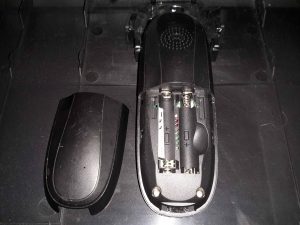
Not much on the back, other than the battery compartment for a pair of AAA rechargables. The base unit contains the charger.

Main PCB
Main PCB

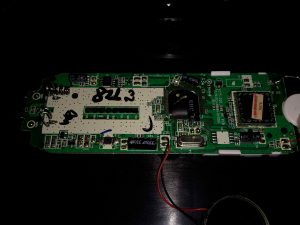
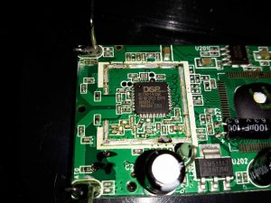
Here’s the main PCB removed from it’s casing. There’s not really much going on, one of the main ICs, which is probably a microcontroller, is a COB device, so no part numbers from there. There’s a row of pads for programming the device at the factory. The RF section is on a dedicated IC, a DE19RF19ZCNC from DSP Group. I couldn’t find much on this part, but it’s one of a range of DECT/VoIP DSP devices.


Base Unit PCB
Base Unit PCB

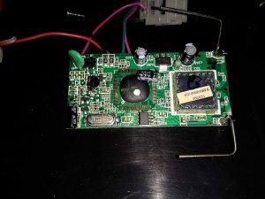
Inside the base unit is a similar board, just without the keypad. Main microcontroller is again a COB device, the RF IC is under the shield.

Main Chipset
Main Chipset

Removing the shield reveals the same IC as in the handset, only this PCB has a pair of antennas.

Posted on Leave a comment

Sony Xperia T Teardown

Back Cover Removed
Back Cover Removed

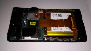
Since this phone has been in my drawer for some time, I figured it was time for a teardown. (It’s never going to see any more use).
The back cover on these phones is easily removed, as it’s just clipped on.

Motherboard
Motherboard

Once the back cover is removed, the Li-Polymer cell is exposed, along with the logic board. Pretty much all of the PCB is under RF shields.

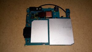
Motherboard Removed
Motherboard Removed
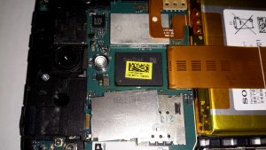
Battery Management
Battery Management

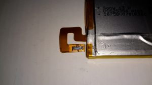
Under the small RF can on the back of the board is the battery management circuitry & the charger. There’s an extra connection to the cell for temperature monitoring. Just under that circuitry is the eMMC flash storage.
Just to the left of the battery circuit is the NFC transceiver IC, from NXP.

Battery Flex
Battery Flex

The cell is connected to the main board with a FFC, with a very small SMT connector, although not as small as the more modern Xperia series phones.

RF Section
RF Section

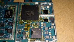
The other side of the mainboard holds the large RF transceiver section, with a Qualcomm RTR8600 multiband transceiver IC. In the bottom corner is a Skyworks SKY77351-32 Quad-band power amplifier IC, along with 3 other power amplifier ICs, also from Skyworks.

Gyro & Audio Codec
Gyro & Audio Codec

The top corner of the board holds the various sensors, including an Invensense MPU-3050 3-axis gyro. To the right of that is the Audio Codec, a WCD9310 from Qualcomm.

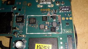
Logic & CPU Section
Logic & CPU Section

Everything is controlled from the last section on the board, with the main CPU & RAM in a PoP (Package-On-Package) configuration. Under the main CPU is the main power management IC, also from Qualcomm. No datasheet for this one unfortunately, but it gives it’s purpose away by being surrounded by large inductors & capacitors.

Posted on Leave a comment

Turnigy Accucell 6 Multi-Chemistry Charger

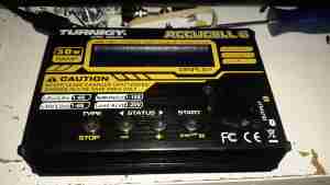
Accucell 6
Accucell 6

A lot of the electronics I use & projects I construct use batteries, mainly of the lithium variety. As charging this chemistry can be a little explosive if not done correctly, I decided a proper charger was required. This charger is capable of handling packs up to 6 cells for Lithium, and up to 20v for lead-acids.

External Connections

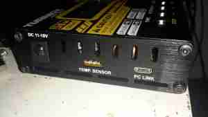
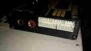
The usual DC input barrel jack on the left, with an external temp sensor for fast charging NiCd/NiMH chemistry batteries. The µUSB port registers under Linux as USB HID, probably so drivers aren’t required. Unfortunately the software is Windows only, but it doesn’t provide anything handy like charging graphs or stats. Just a way to alter settings & control charging from a PC. On other versions of this charger there’s a setting to change the temp sensor port into a TTL serial output, which would be much handier.

Output & Balance
Output & Balance

The other side of the charger has the main DC output jacks & the pack balancing connections.

Cover Removed
Cover Removed

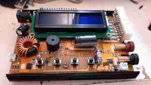
Here’s the top cover removed from the charger, showing most of the internals. A standard HD44780 LCD provides the user interface, the CPU & it’s associated logic is hidden under there somewhere.
The PCB has nice heavy tracks to handle the 6A of current this charger is capable of.

Balancing Network
Balancing Network

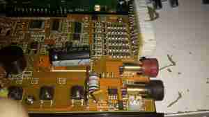
The output side of the board. Here the resistive pack balancing network can be seen behind the vertical daughter board holding the connectors, along with the output current shunt between the DC output banana jacks & the last tactile button.

Main Logic
Main Logic

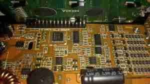
Unfortunately the LCD is soldered directly to the board, and my desoldering tool couldn’t quite get all the solder out, so time to get a bit violent. I’ve gently bent the header so I could see the brains of the charger. The main CPU is a Megwin MA84G564AD48, which is an Intel 8081 clone with USB support. Unfortunately I was unable to find a datasheet for this part, and the page on Megwin’s site is Chinese only.

I was hoping it was an ATMega328, as I have seen in other versions of this charger, as there are custom firmwares available to increase the feature set of the charger, but no dice on this one. I do think the µUSB port is unique to this version though, so avoiding models with that port probably would get a hackable version.
There’s some glue logic for controlling the resistor taps on the balancing network, and a few op-amps for voltage & current readings.

Power Switching Devices

All the power diodes & switching FETs for the DC-DC converter are mounted on the bottom of the PCB, and clamped against the aluminium casing when the PCB is screwed down. Not the best way to ensure great contact, but Chinese tech, so m’eh.

Posted on Leave a comment

Cree XML-T6 x5 LED Torch

Here’s another torch from eBay, this time with 5 Cree XML-T6 LEDs.

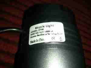
Label
Label

Having 5 Cree LEDs rated at up to 3A a piece, this light has the capacity to draw about 50W from it’s power supply. In this case though, current draw is about 1.5A at 12v input on the full brightness setting.

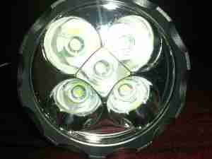
Cree LED Torch
Cree LED Torch

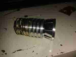
Here’s the LEDs mounted into the reflector. Fitting this many high power LEDs into a small space requires some serious heatsinking. The casing is made of machined aluminium.

LED Module
LED Module

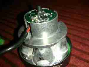
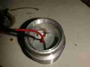
Unscrewing the front bezel allows the internals to come out. The core frame & reflector is all cast alloy as well, for heatsinking the LEDs. The controller PCB is mounted into a recess in the back of the LED mount.

Controller
Controller

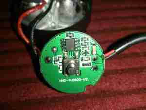
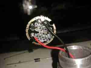
Here’s the controller itself. The usual small microcontroller is present, for the multiple modes, and handling the momentary power switch.

Switching Inductor
Switching Inductor

As all the LEDs on this torch are connected in series, their forward voltage is ~12-15v. The battery is an 8.4v Li-Ion pack, so some boost conversion is required. This is handled by the circuitry on the other side of the board, with this large power inductor.

Reflector
Reflector

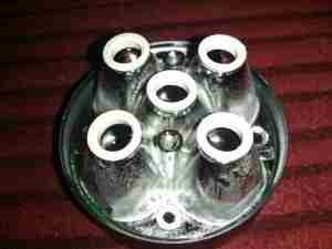
The reflector screws onto the front of the LED array, centered in place with some plastic grommets around the LEDs themselves.

LED Array
LED Array

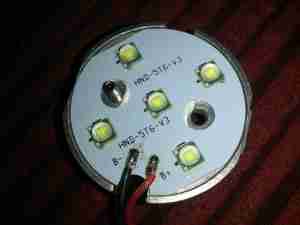
Finally for the torch, the LED array itself. This is attached to the frame with some thermal adhesive, and the LEDs themselves are mounted on an aluminium-core PCB for better heat transfer.
This module unsurprisingly generates quite some heat, so I have improved the thermal transfer to the outer case with some thermal grease around the outer edge.

Charger
Charger

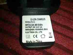
The supplied charger is the usual Chinese cheapy affair, claiming an output current of 1A at 8.4v. I never use these chargers, so they get butchered instead.

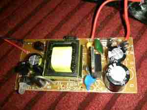
Charger PCB
Charger PCB

Here’s the main PCB. Overall the construction isn’t that bad, the input mains is full-wave rectified, but there is little in the way of RFI filtering. The supply is fused, but with an absolutely tiny glass affair that I seriously doubt has the ability to clear a large fault current.
Like many cheap supplies, the output wiring is very thin, it’s capacity to carry 1A is questionable.

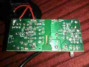
PCB Reverse
PCB Reverse

On the reverse side, there’s a nice large gap between the mains side & the low voltage output. There’s even an anti-tracking slot under the optoisolator.

Posted on 7 Comments

Maplin/Refrakta XR-E LED Torch

Following on from the teardown & analysis of the charger, here’s the torch itself under the spotlight.

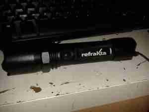
LED Torch
LED Torch

Here’s the torch itself, it’s a sturdy device, made of aluminium. Power is provided by a single 18650 Li-Ion cell.

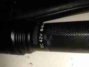
Charging Port
Charging Port

Here’s the charging port on the torch, there’s no electronics in here for controlling the charge, the socket is simply connected directly to the Li-Ion cell, and requires a proper external charger.

LED Pill
LED Pill

Unscrewing the lens gives access to the LED core, this also unscrews from the torch body itself, leaving the power switch & the battery in the body.

LED Module
LED Module

Unscrewing the aluminised plastic reflector reveals the LED itself. Being a new device, I expected an XM-L or XM-L2 Cree LED in here, but it’s actually an XR-E model, a significantly older technology, rated at max 1A of drive current.

LED Back
LED Back

Popping the control PCB out from the pill reveals a lot of empty space, but the back of the LED is completely covered by a heatsinking plate, which is conducting heat to the main body of the torch.

Control PCB
Control PCB

Not much to see on the control PCB, just a bunch of limiting resistors, and a multi-mode LED driver IC in a SOT-23 package. There’s no proper constant-current LED driver, and as the battery discharges the torch will dim, until the low voltage cutout on the cell turns things off completely.

Posted on Leave a comment

Maplin LED Torch Charger Replacement

In my previous post, I mentioned I’d be replacing the factory supplied charging gear with something that actually charges lithium chemistry cells correctly.

Charging Base
Charging Base

Here’s the base as supplied, with an indicator LED on the right hand side. This LED indicates nothing other than power being applied to the charging base. It’s just connected across the power input with a resistor. This also means that any battery left in the charger while it’s unplugged will discharge itself through this LED over time. Great design there China!

PCB Removed
PCB Removed

Here I’ve removed the PCB – there’s no need for it to be taking up any space, as it’s just a complete waste of copper clad board in the first place. The battery tabs have been desoldered & hot snot used to secure them into the plastic casing.

USB Hole
USB Hole

The charger modules I use are USB powered, so a small hole has been routed out in the casing to allow access to the port.

Charging Module
Charging Module

Here the charging module has been installed & wired to the battery tabs. Output is now a nice 4.18v, and will automatically stop charging when the cell is full.
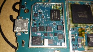
Safety has been restored!

73s for now folks!
Posted on Leave a comment

Lethal Chinese Mains Adaptors

With every piece of Chinese electronics I obtain, mainly Baofeng radios, they come with a Europlug-type power adaptor, and a universal plug adaptor for the mains.

The charger units aren’t too bad, there’s a fair amount of isolation between the primary & secondary, and even though they’re very simple & cheap, I can’t see any immediate safety problems with them.

The plug adaptors, however, are a different matter. These things are utterly lethal!
Baofeng PSU
Baofeng PSU

Here’s the inside of the PSU. It’s just a very simple SMPS, giving an output of 10v 500mA. The fuse is actually a fusible resistor.

PCB Reverse
PCB Reverse

Here’s the back of the PCB with the SMPS control IC. I can’t find any English datasheets for this part unfortunately.

Universal Travel Adaptor

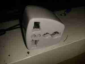
Here’s the dangerous adaptor. There’s no safety shield, so the live parts are exposed.

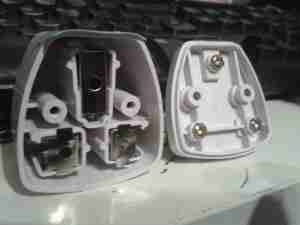
Internals
Internals

Here’s the adaptor split apart. The output contacts are on the left, and rely just on pressure to make contact with the brass screws on the mains input pins to provide power.
This is a very poor way to get a connection, a dirty or worn contact here would create a lot of heat if any significant power is pulled through, and could quite possibly result in a fire.

Not surprisingly, I bin these things as soon as I open the box, and charge all my radios with a 12v charging system.

Posted on Leave a comment

Mobile Radio Shack Bag

There are times when I am frequently away from home base, usually either on the canal system or at a festival. During these times it’s very handy to be able to just grab a bag, without having to be concerned about sorting everything out.

This post will only detail the portable shack bag. The power supply kit that goes along with it with be detailed in another post.

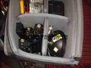
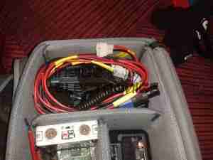
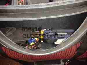
The bag I use is an VHS Camcorder bag from the early 80’s. It’s very well built, & copes easily with the weight of all the radio gear.

Total weight for this system is 13.4lbs (6kg).

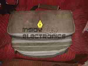
Mobile Radio Bag
Mobile Radio Bag

Above is the bag packed. Obligatory International Ameteur Radio Symbol patch front & centre. Being an old camera bag, this easily slings over the shoulder, with it’s padded strap.

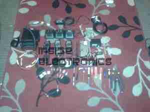
Current Equipment
Current Equipment

Here is all the current equipment laid out. All the equipment to enable me to set up a station anywhere.
In the following photos I will go into the details.

Main Radio
Main Radio

First off, my main radio. This is the same Wouxun KG-UV950P mobile rig I have posted about previously. I have heatshrunk the power cable to keep it together & attached my standard power connector to the end. More on these later on.

HTs
HTs

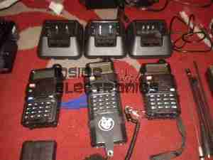
In the bag I also carry three Baofeng UV-5R handhelds. Extremely useful for short range site communications, along with their charger bases. The charging base on the right has been slightly modified to support charging of my main LED torch as well, which uses similar Li-Ion based packs as the Baofengs.

Baofeng 12v Charger
Baofeng 12v Charger

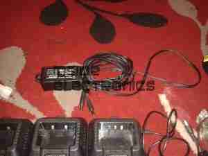
As the charger bases for the Baofeng HTs take a supply of 10v DC, I have constructed a 12v adaptor system for them. (Which utter prat of an engineer at Baofeng picked 10v?)

Linear Amplifier & SWR Meter

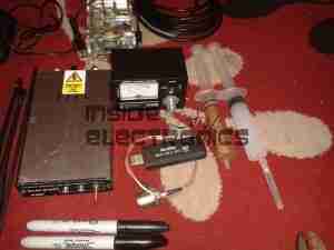
Also included is a small Alinco ELH-2320 35W 2m linear amplifier. This was given to me from the local HackSpace in Manchester. (They don’t have any ham members, besides myself). Also here is my small SWR & Power meter, SDR kit & a pair of syringes. These are filled respectively with Copaslip copper loaded grease, (very good for stopping fasteners exposed to the weather from seizing up), and dielectric silicone grease. (I use this stuff for filling connectors that are exposed to the weather – keeps the water out).

Tools
Tools

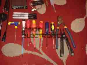
I always keep essential tools in the bag, here is the small selection of screwdrivers which fit pretty much any screw fastener around, my heavy-duty cable shears (these buggers can cut through starter cable in one go!) and my trusty Gerber Diesel multitool.

Magmount & Pi
Magmount & Pi

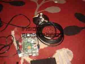
Main antenna magmount & a spare Raspberry Pi.

Antenna, Patch Leads, Etc.

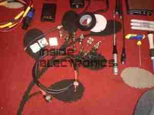
Finally, the antennas for the HTs, main dual-band antenna (Nagoya SP-45) for the magmount, a small selection of spare plugs, sockets & adaptors. Also here is a roll of self-amalgamating tape, very handy for waterproofing wiring connections (especially when used in conjunction with the silicone grease), & a roll of solder wick.

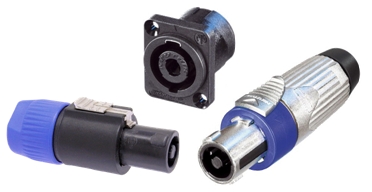
Now, the main power connectors of choice for my equipment are Neutrik SpeakOn type connectors:

Neutrik SpeakOn
Neutrik SpeakOn

These connectors have many advantages:

  • They are positive locking connectors. No more loose connections.
  • They have a high continuous current rating of 30A RMS.
  • Relatively weather resistant.

Also, they have two pairs of pins – and as some of my bigger non-radio related equipment is 24v, this allows me to use a single set of plugs for everything. Without having to worry about plugging a 12v device into a 24v socket, and letting out the magic blue genie.

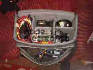
Once everything is packed up, here’s the bag:

Packed
Packed

Everything has a neat little pocket for easy access. Some closeups below.

HTs, Magmount
HTs, Magmount
Chargers, Amplifier
Chargers, Amplifier
Main Radio
Main Radio
Small Stuff
Small Stuff

I will post more about my portable power system later on, as this bit of my kit is being revamped at the moment.

Stay tuned!

Posted on Leave a comment

Potentially Lethal Clone Apple Charger

Charger
Charger

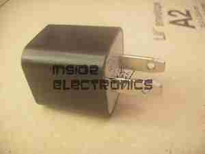
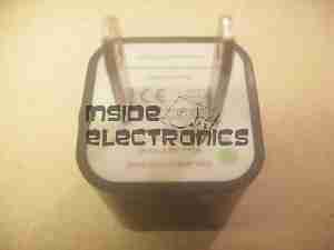
I received this USB supply with a laser module from China that I purchased on eBay. I have heard of these nasty copies of Apple chargers going around, but I’d never received one this bad with a piece of Chinese electronics.

Label
Label

Model No. A1265, so definitely an Apple clone. Apparently capable of +5v DC 1A output. Notice the American NEMA pins. This wouldn’t have been any use to me in the first instance since I am resident in the UK & our mains plugs are significantly different, not to mention significantly safer.

Manufacturer is marked as Flextronics.

Top Of Boards
Top Of Boards

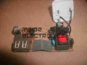
Here is the charger disassembled. Inside the case these two boards are folded together, creating an alarmingly small isolation gap between the mains side of the supply & the 5v output. Both the low voltage output & the feedback loop for the supply runs over the 4-core ribbon cable.
The mains wiring from the board is as thin as hair, insulation included, so there is a big possibility of shorts all over the place from this part of the circuit alone.

Bottom Of Boards
Bottom Of Boards

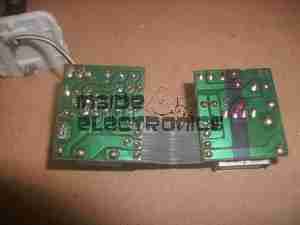
Bottom of the PCB assemblies. Good luck finding any creepage distance here. There simply isn’t any at all. traces on the +350v DC rail on the mains side of the transformer are no more than 1mm away from the supposedly isolated low voltage side.

Plugging one of these devices into anything is just asking for electrocution.


Posted on Leave a comment

BigBen DSi Inductive Charging Dock

Front
Front

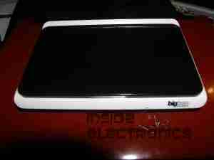
Here is a Inductive charger designed for the Nintendo DSi. Cheap Chinese build, but it does work!

Overview
Overview

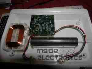
Top has been removed from the unit here. Most prominent in the centre is a solid steel bar, simply there to give the device some weight.
Pair of Tri-colour LEDs at the front indicates charging status.
Induction coil is on the left, with the controller & oscillator PCB at the top.

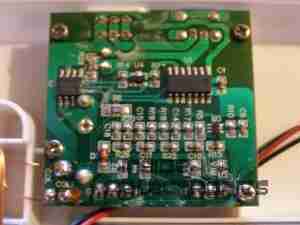
PCB Closeup
PCB Closeup

Closeup of the PCB, ICs have had their markings ground off.

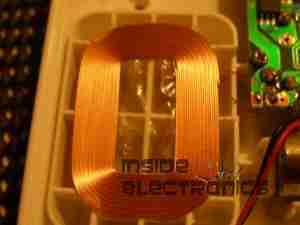
Coil
Coil

Induction coil. This couples power into a coil built into a special battery, supplied with the base, to charge it when the DSi is placed on the dock.

Label
Label

Information Label on the base.

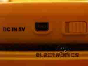
Power Input
Power Input

Standard DSi charger port, connects to the charger you get with the DSi. Power switch is on the right.

Posted on Leave a comment

Portable Power Pack Charger

A quick update to my portable power pack, a mains charging port. Uses a universal DC barrel jack.

Connection to the battery. 1N4001 reverse protection diode under the blue heatshrink tubing. I used a surplus PC CD-ROM audio cable (grey lead). Seen here snaking behind the battery to the DC In Jack.

Posted on Leave a comment

Bosch GSR 14.4v Pro Drill-Driver

Drill Case
Drill Case

Here is a Bosch 14.4v Professional cordless drill/driver, recovered from a skip!
It was thrown away due to a gearbox fault, which was easy to rectify.

Internals
Internals

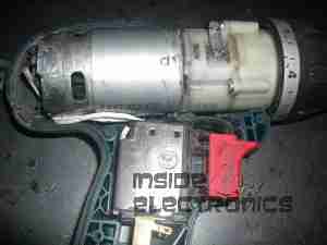
Here is the drill with the side cover removed, showing it’s internal parts. The speed controller is below the motor & gearbox here. The unit at the top consists of a 12v DC motor, coupled to a 4-stage  epicyclic gearbox unit, from which can be selected 2 different ratios, by way of the lever in the centre of the box. This disables one of the gear stages. There is a torque control clutch at the chuck end of the gearbox, this was faulty when found.

Motor
Motor

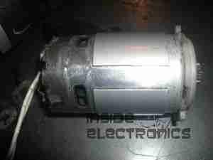
Here is the drive motor disconnected from the gearbox, having a bayonet fitting on the drive end.

Drive Gear
Drive Gear

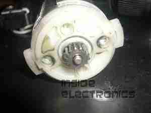
This is the primary drive gear of the motor, which connects with the gearbox.

Cooling Fan
Cooling Fan

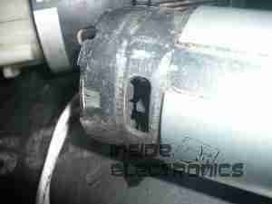
The motor is cooled by this fan inside next to the commutator, drawing air over the windings.

Gearbox
Gearbox

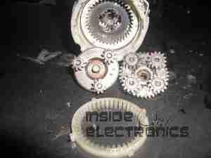
This is the gearbox partially disassembled, showing the 1st & second stages of the geartrain. The second stage provides the 2 different drive ratios by having the annulus slide over the entire gearset, disabling it entirely, in high gear. The annulus gears are a potential weak point in this gearbox, as they are made from plastic, with all other gears being made of steel.

Charger
Charger

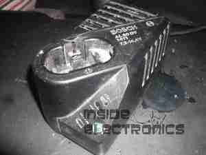
Here is the charging unit for the Ni-Cd battery packs supplied with the drill. The only indicator is the LED shown here on the front of the unit, which flashes while charging, & comes on solid when charging is complete. Charge termination is by way of temperature monitoring.

Transformer
Transformer

Here the bottom of the charger has been removed, showing the internal parts. An 18v transformer supplies power to the charger PCB on the left.

Charger PCB
Charger PCB

This is the charger PCB, with a ST Microelectronics controller IC marked 6HKB07501758. I cannot find any information about this chip.

Battery Pack Internals

Here is a battery pack with the top removed, showing the cells.

Temperature Sensor
Temperature Sensor

This is the temperature sensor embedded inside the battery pack that is used by the charger to determine when charging is complete.

Posted on Leave a comment

Nokia 7110

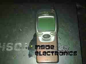
Front
Front

Another phone from the mid 90s. This is the nokia 7110.

Slider Open
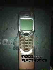
Slider Open

Here the slider is open showing the keypad.

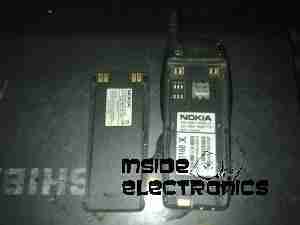
Battery Removed
Battery Removed

Here the battery is removed, a Li-Ion unit.

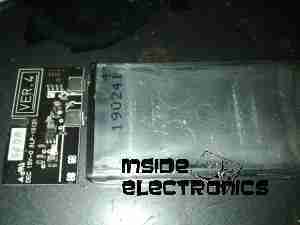
Battery
Battery

The battery cell & protection circuit removed from the casing.

Rear Of PCB
Rear Of PCB

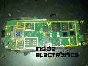
This is the rear of the PCB removed from the housing. Data & charging ports on the right hand side f the board.

Front Of PCB
Front Of PCB

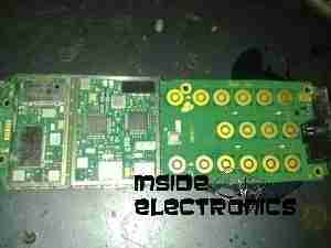
Front of the PCB with the RF sections at the left hand side & the keypad contacts on the right.

RF Sections
RF Sections

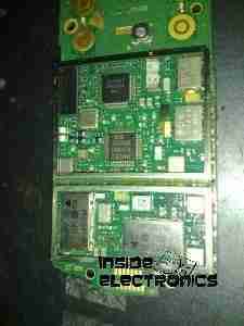
Closeup of the RF sections of the board, big silver rectangular cans are VCO units.

SIM Connector
SIM Connector

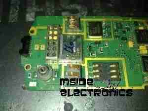
Closeup of the top rear section of the PCB, with SIM cnnector, battery contacts, IR tranciever at the far left. Bottom centre is the external antenna connector.

CPU
CPU

The logic section of the board, Large chip is CPU, to right of that is the ROM storing the machine code. Other chips are unknown custom parts.

Mic & Speaker
Mic & Speaker

The Mic & the loudspeaker removed from it’s housing.

LCD
LCD

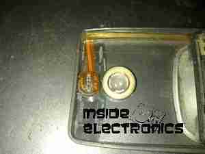
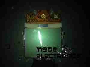
LCD from the front of the unit, SPI interfaced. Flex PCB also contains the power button, loudspeaker contacts & a temperature sensor.

Scroll Wheel
Scroll Wheel

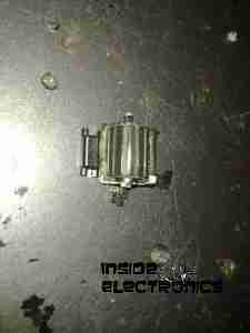
The scroll wheel removed from the front housing.

Vibra-Motor
Vibra-Motor

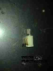
Tiny vibration motor removed from the rear housing, alerts the user to a text or phone call.