Posted on Leave a comment

ELuc BLU4 Intelligent Lithium Battery Charger W/Bluetooth

BLU4 Battery Charger

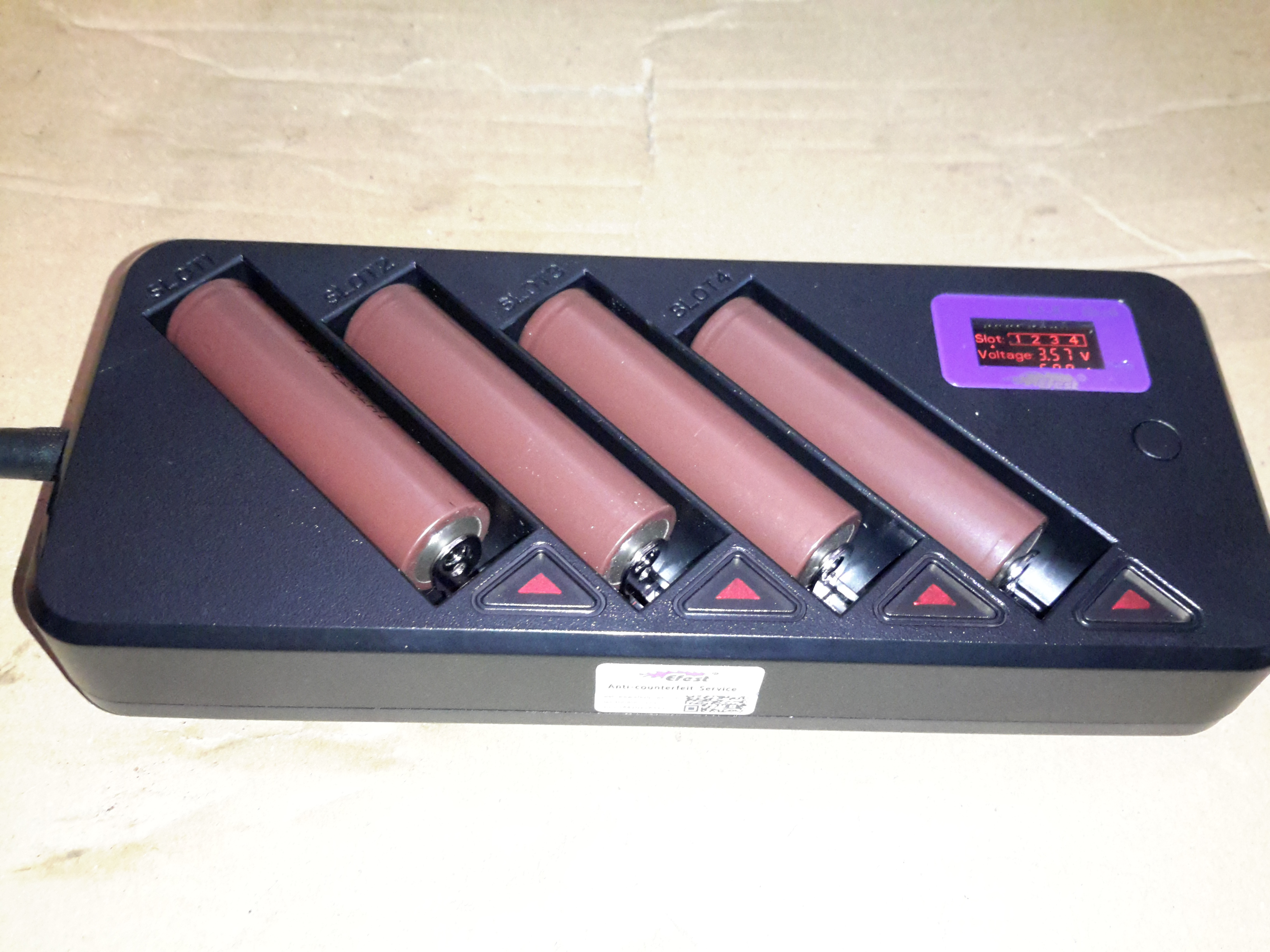
Here’s another battery charger designed for lithium chemistry cells, the BLU4. This charger doesn’t display much on it’s built in LCD, apart from basic cell voltage & charging current limits, as it has a built in Bluetooth module that will link into an Android or iOS app.

Above the charger is operating with 4 brand new cells, at a current of 500mA per cell. If only a pair of cells is being charged, the current can be increased to 1A per cell.

LCD
LCD

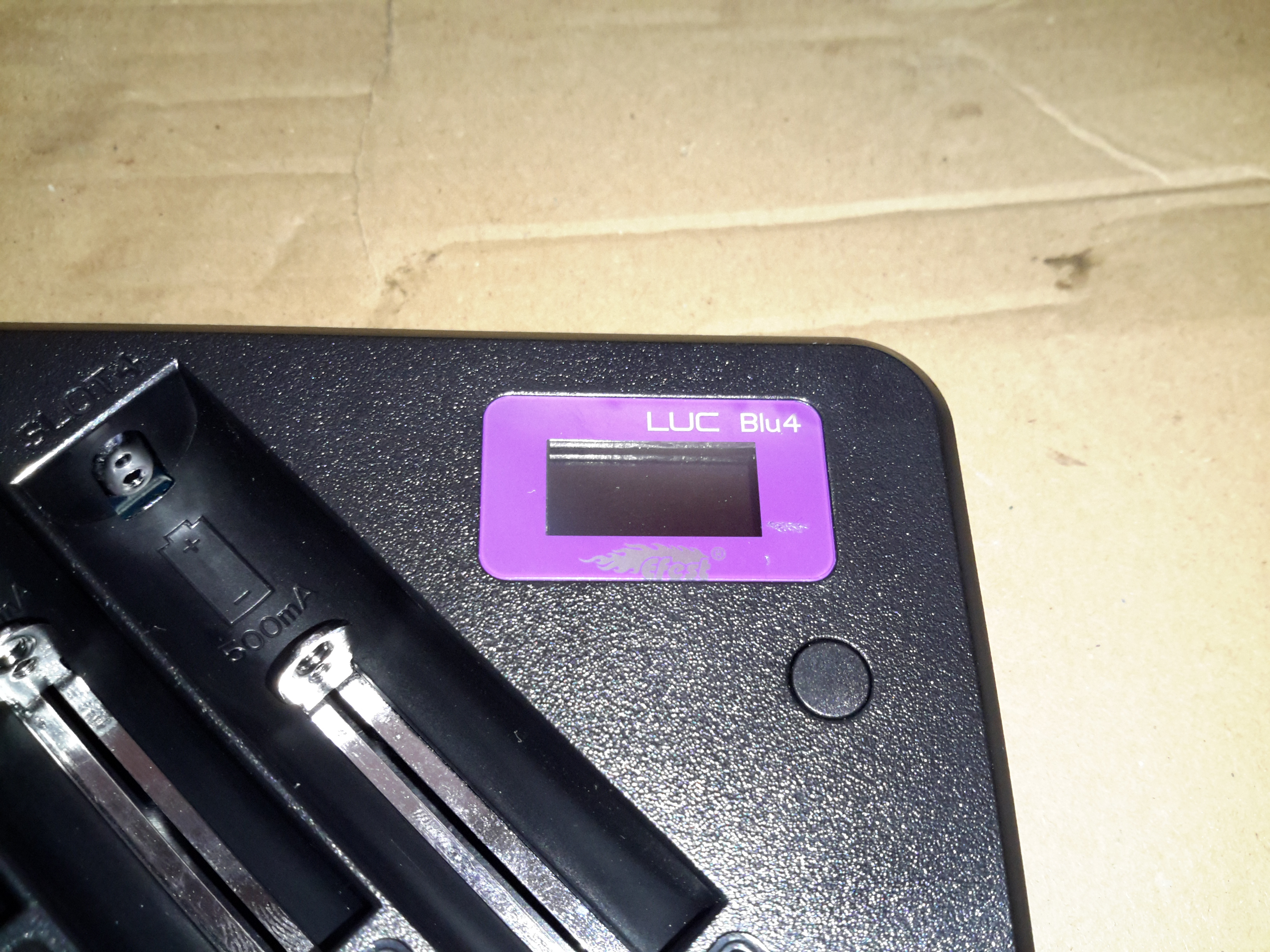
Not much in the way of user interface on the charger, a tiny LCD & single button for cycling through the display options.

Dataplate
Dataplate

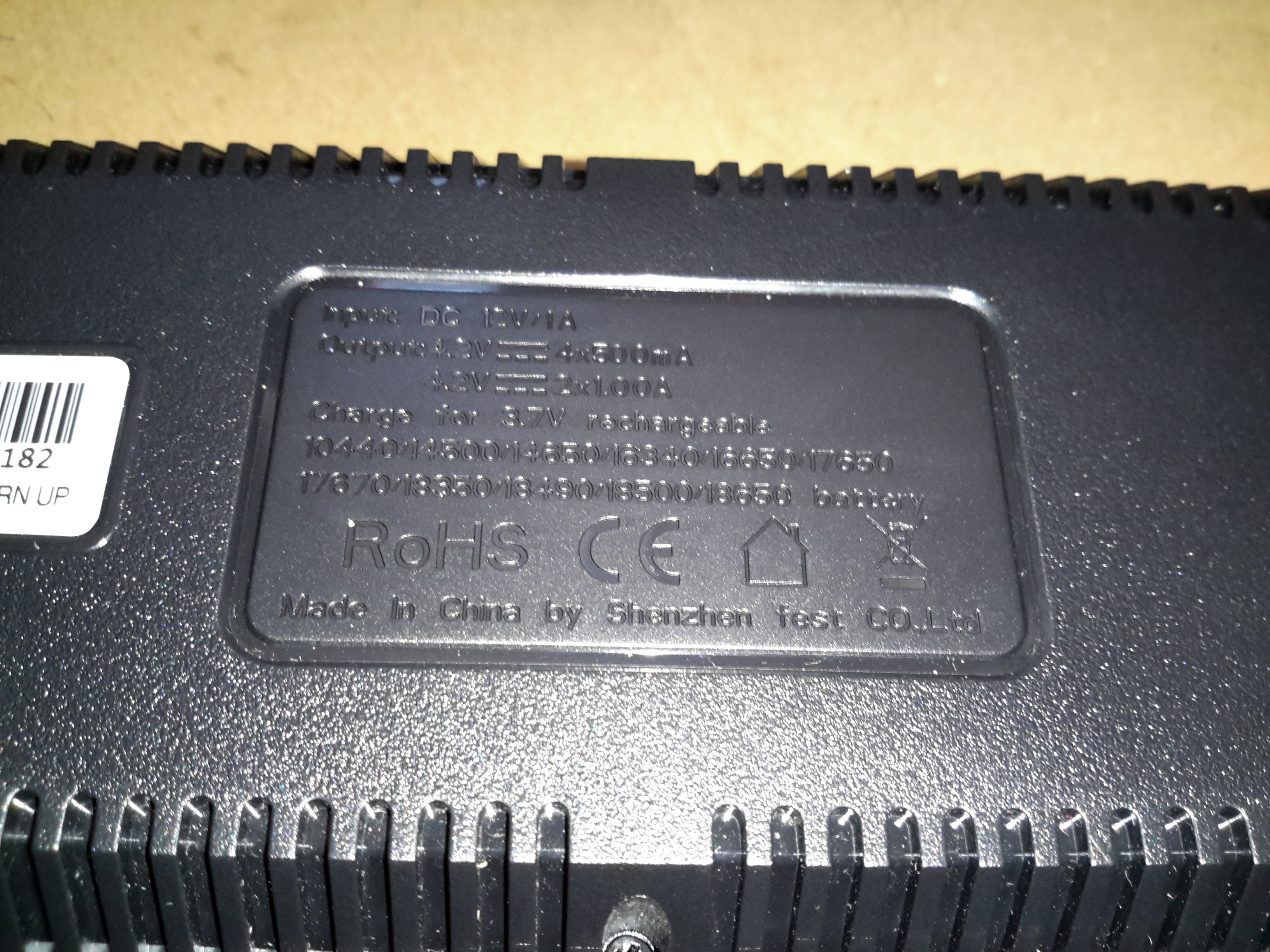
The usual stuff on the data plate, the charger accepts an input of 12v DC at 1A.

Bottom Cover Removed

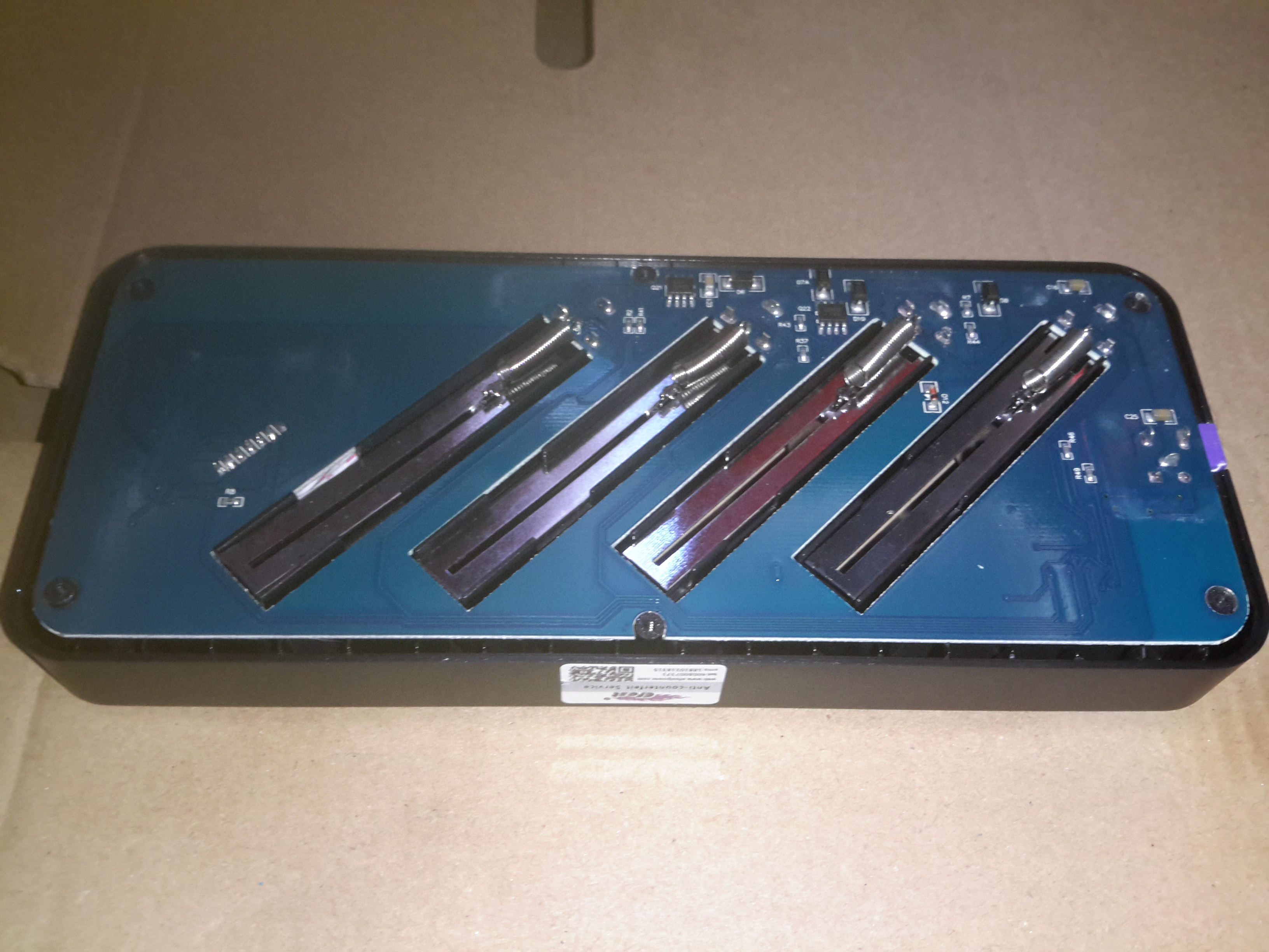
Removing the 6 screws on the bottom of the casing allows the board to be seen. Not much on the bottom, the 4 cell negative connections can be seen, with their springs for adjusting for cell length.

MOSFETs
MOSFETs

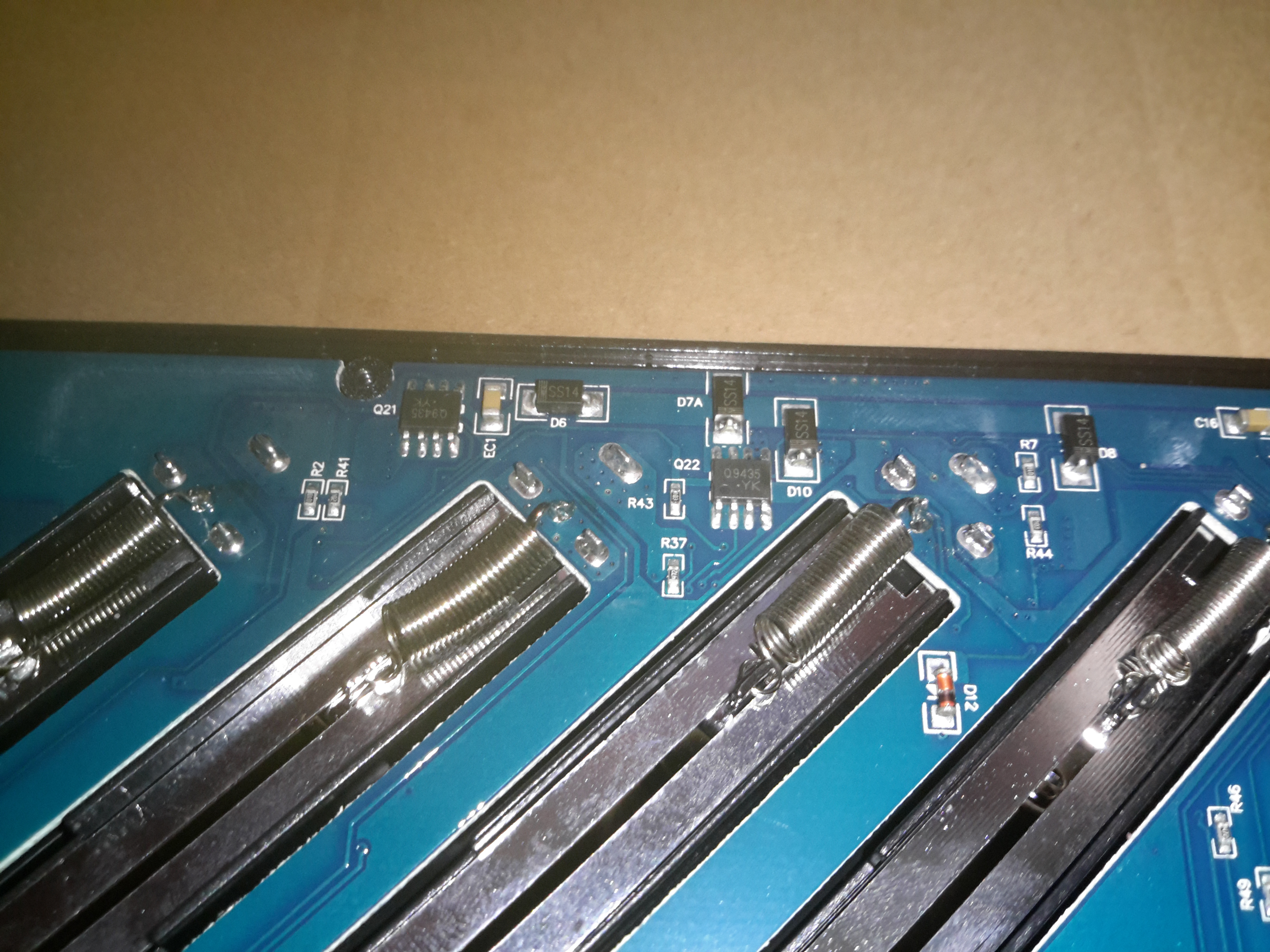
There’s a couple of P-Channel FETs on the bottom side for the charging circuits, along with some diodes.

Main PCB
Main PCB

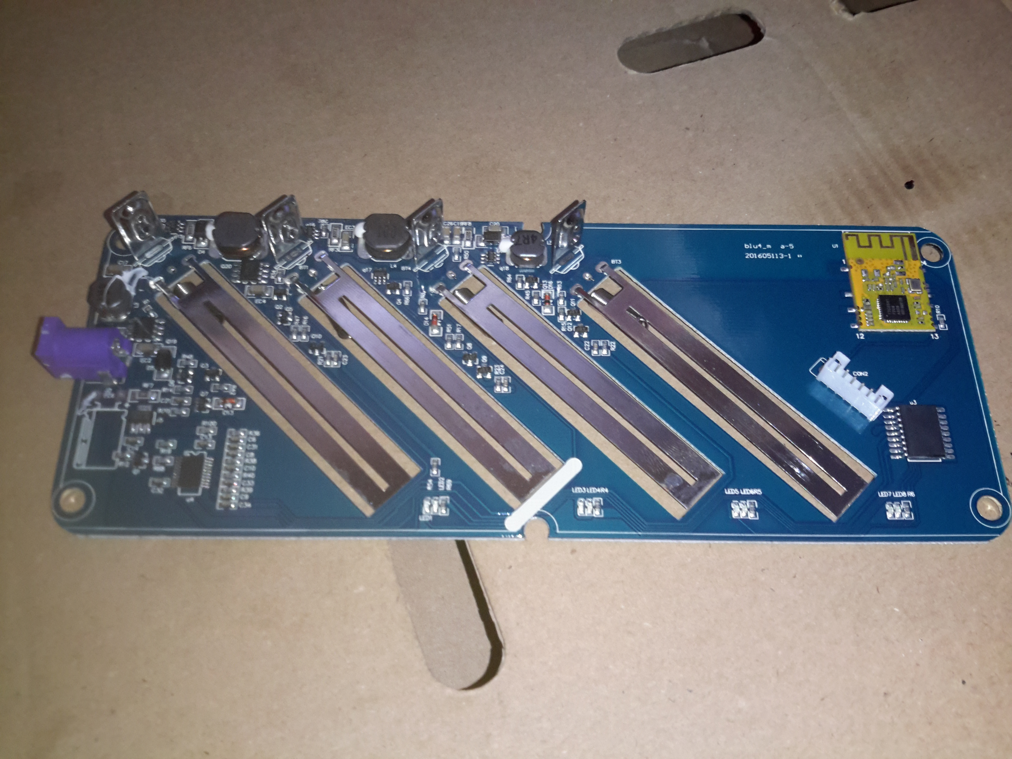
The main PCB is easily removed after the springs are unhooked from the terminals. Most of the power circuitry is located on the top side near the power input. There are 4 DC-DC converters on board for stepping the input 12v down to the 4.2v required to charge a lithium cell.

Second Controller
Second Controller

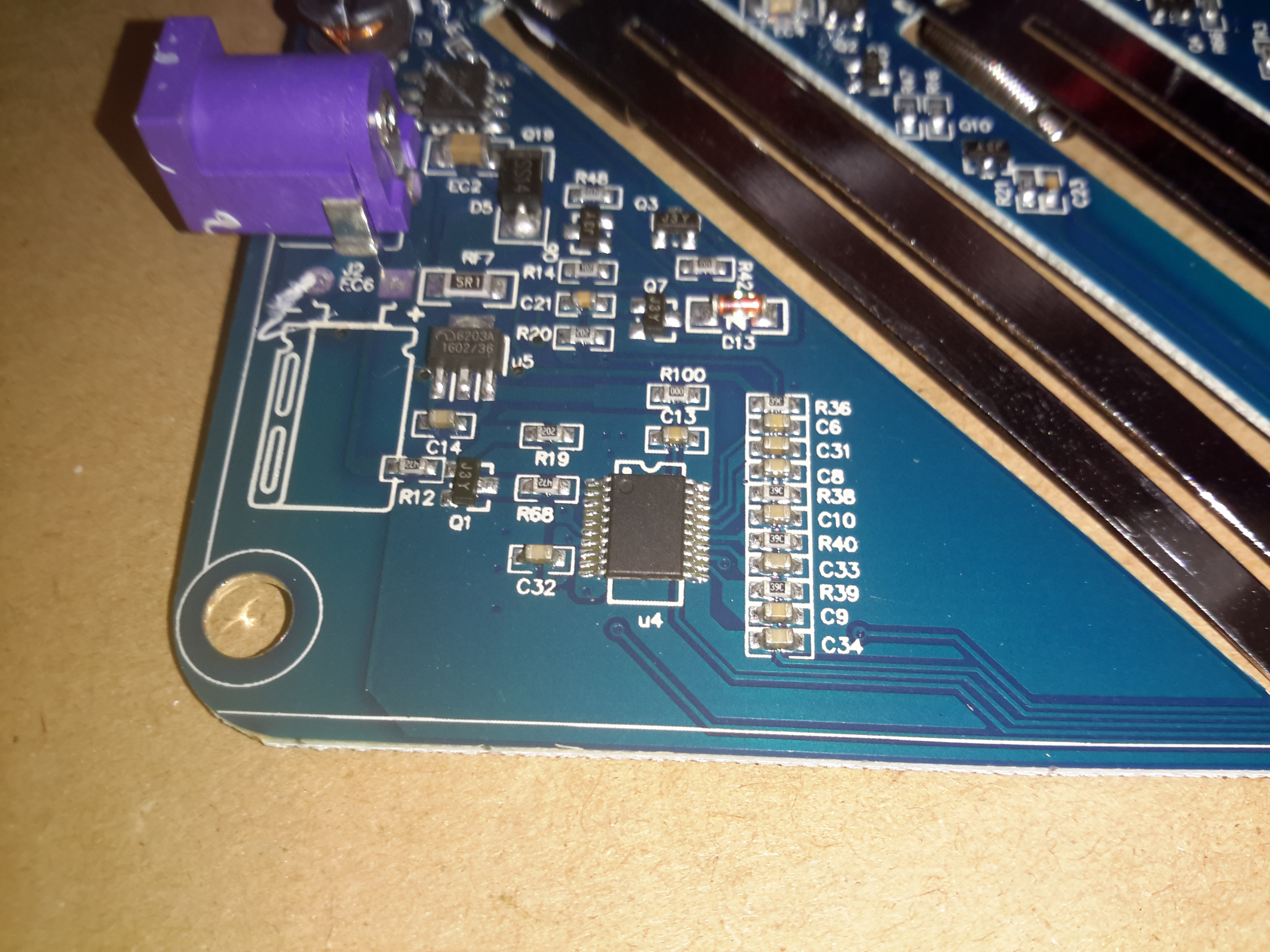
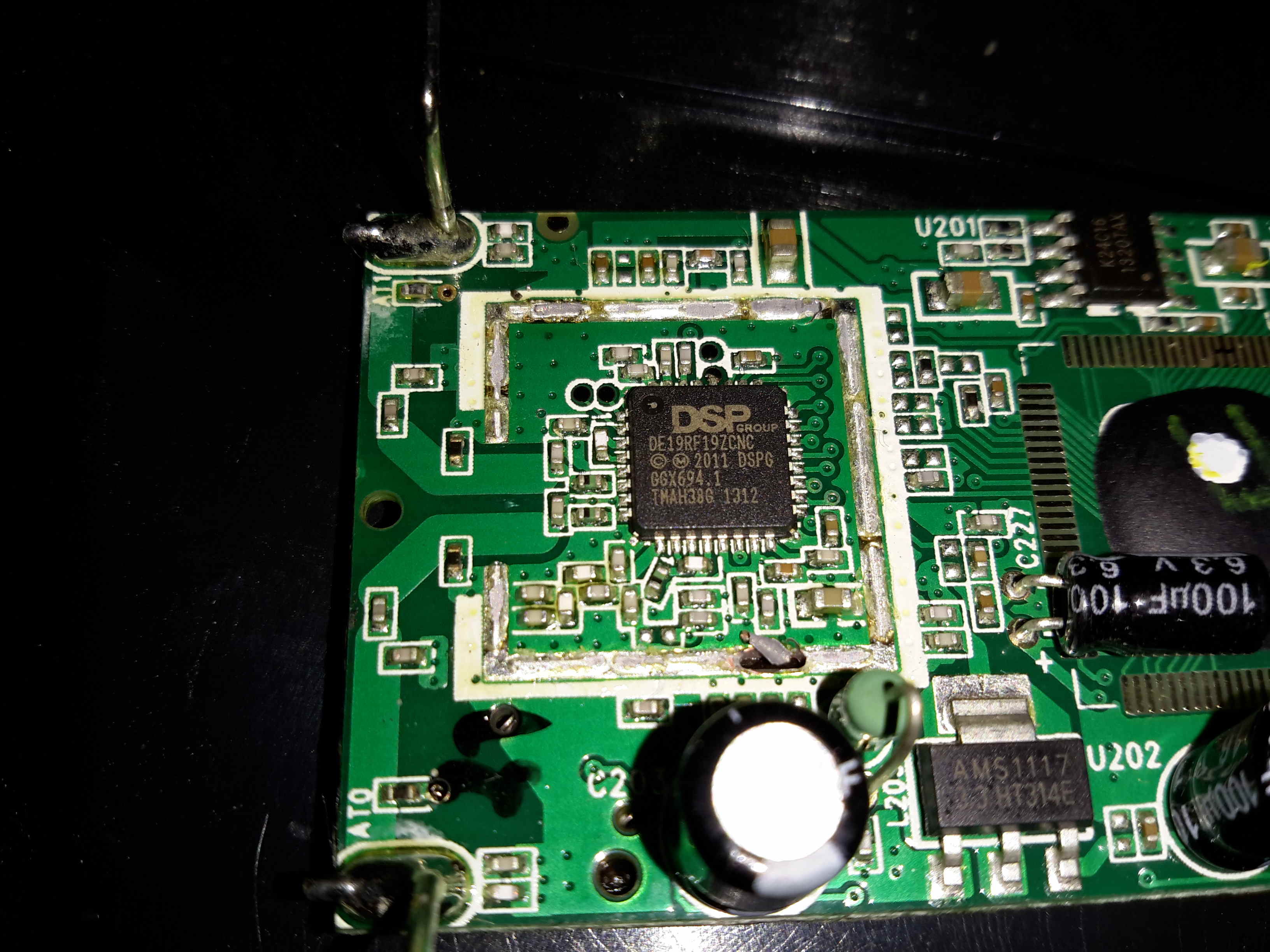
Not entirely sure what this IC is in the bottom corner, as it’s completely unmarked. I’m guessing it’s a microcontroller though.

DC Input Side
DC Input Side

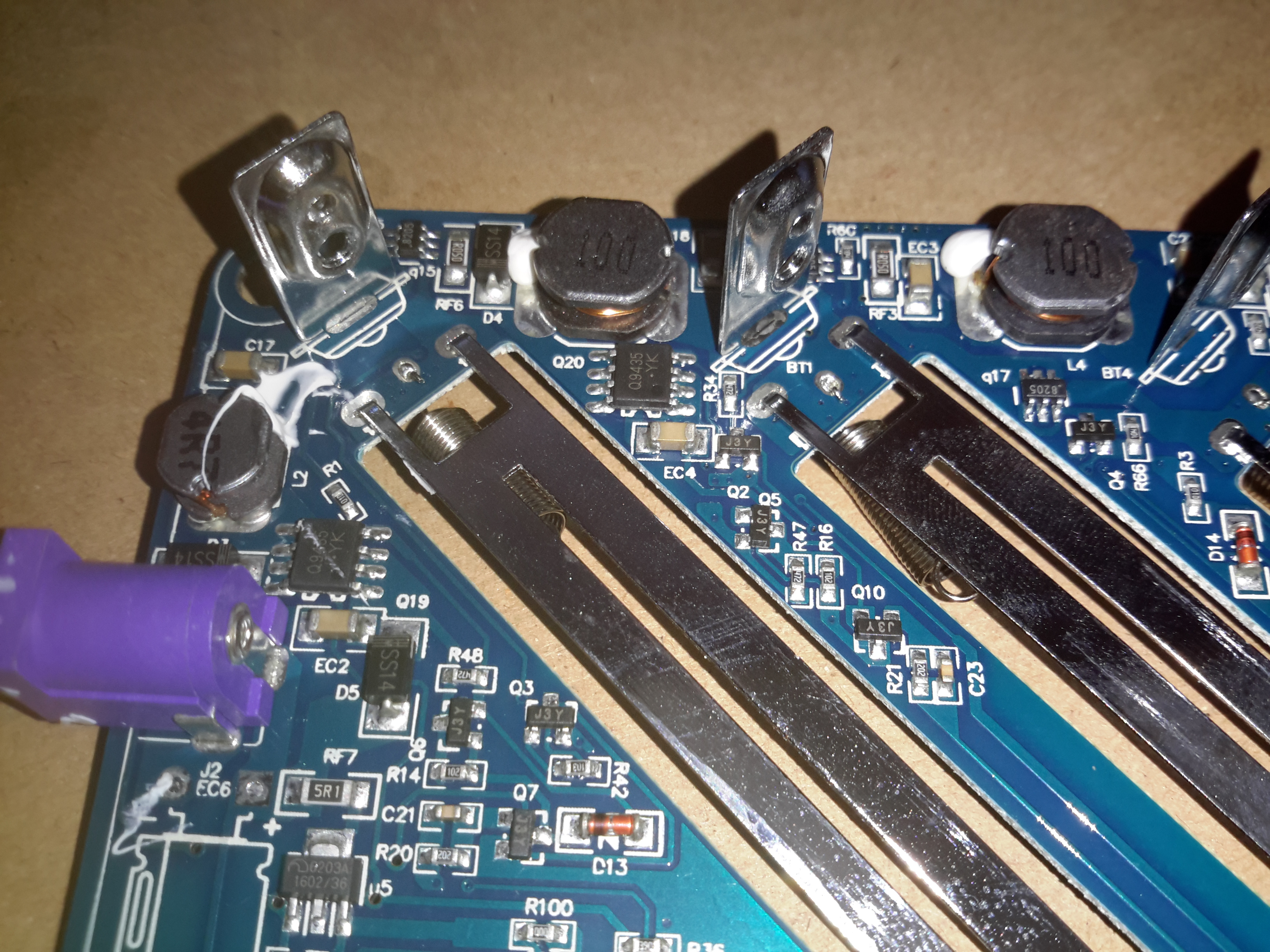
The top left of the board is crammed with the DC-DC converters, all the FETs are in SO8 packages.

DC-DC Converters
DC-DC Converters

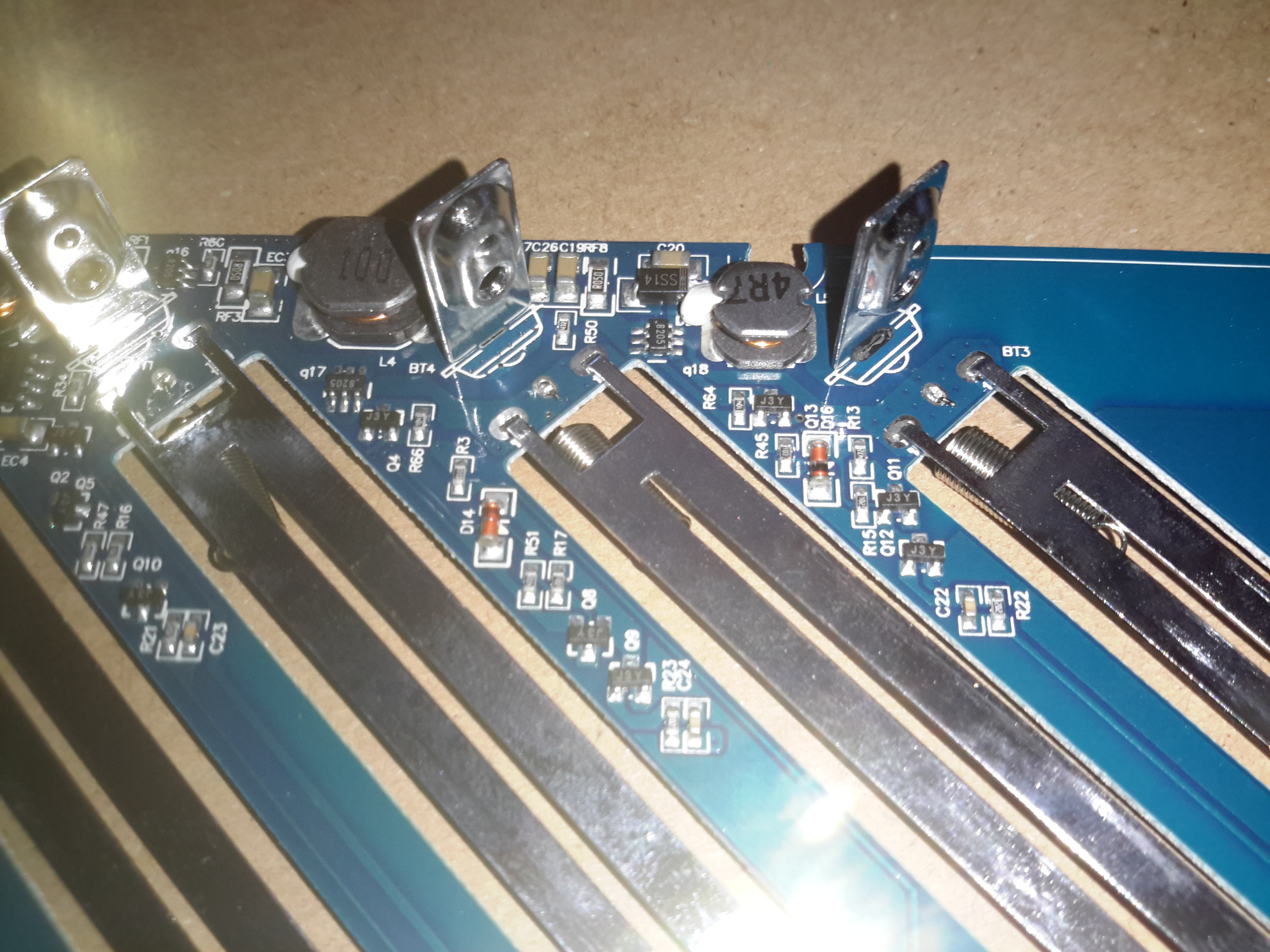
One pair of DC-DC inductors is larger than the other pair, for reasons I’m unsure of.

Bluetooth Module
Bluetooth Module

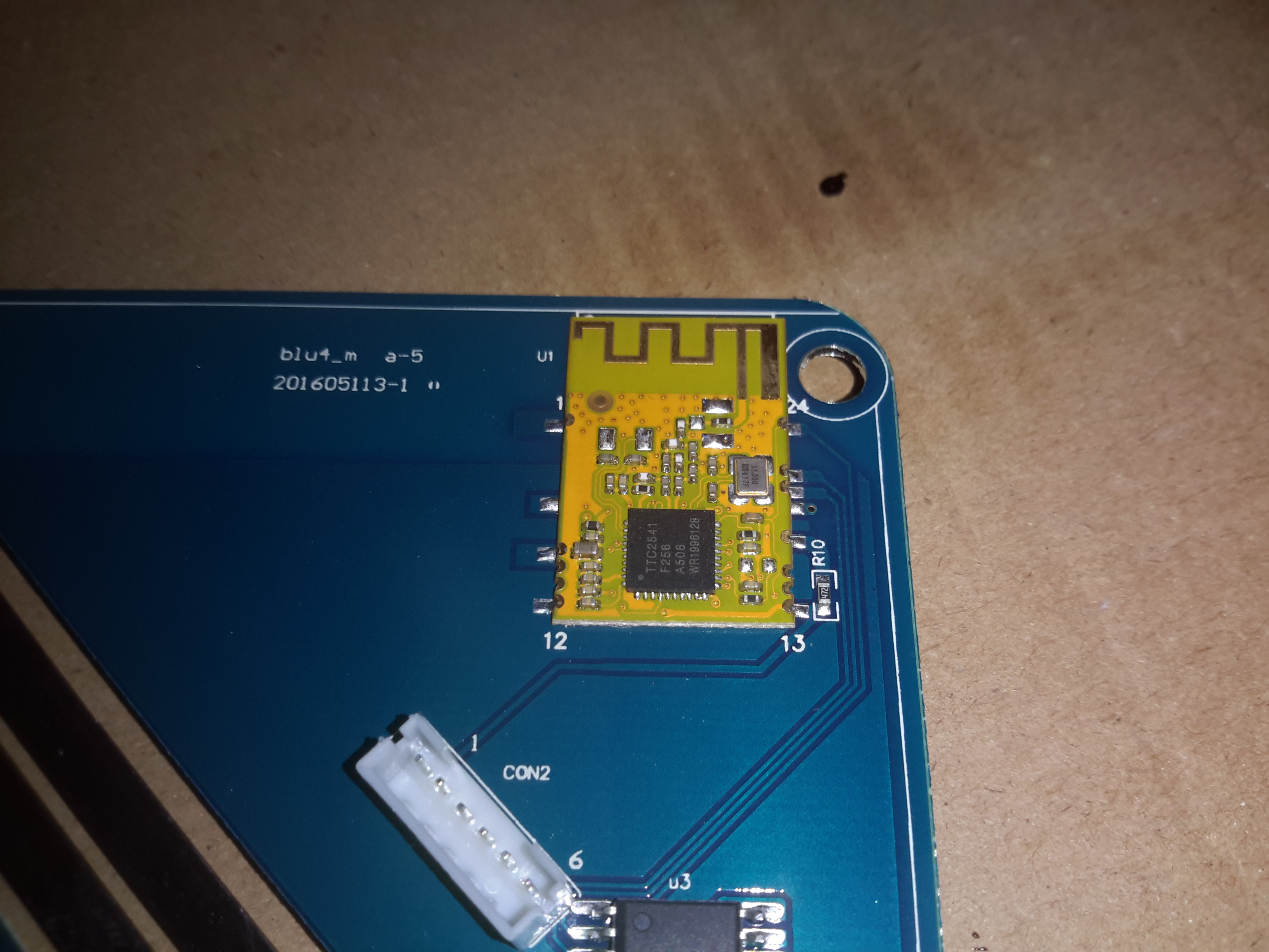
Bluetooth connectivity is provided by this module, which is based around a TTC2541 BLE IC.

Microcontroller
Microcontroller

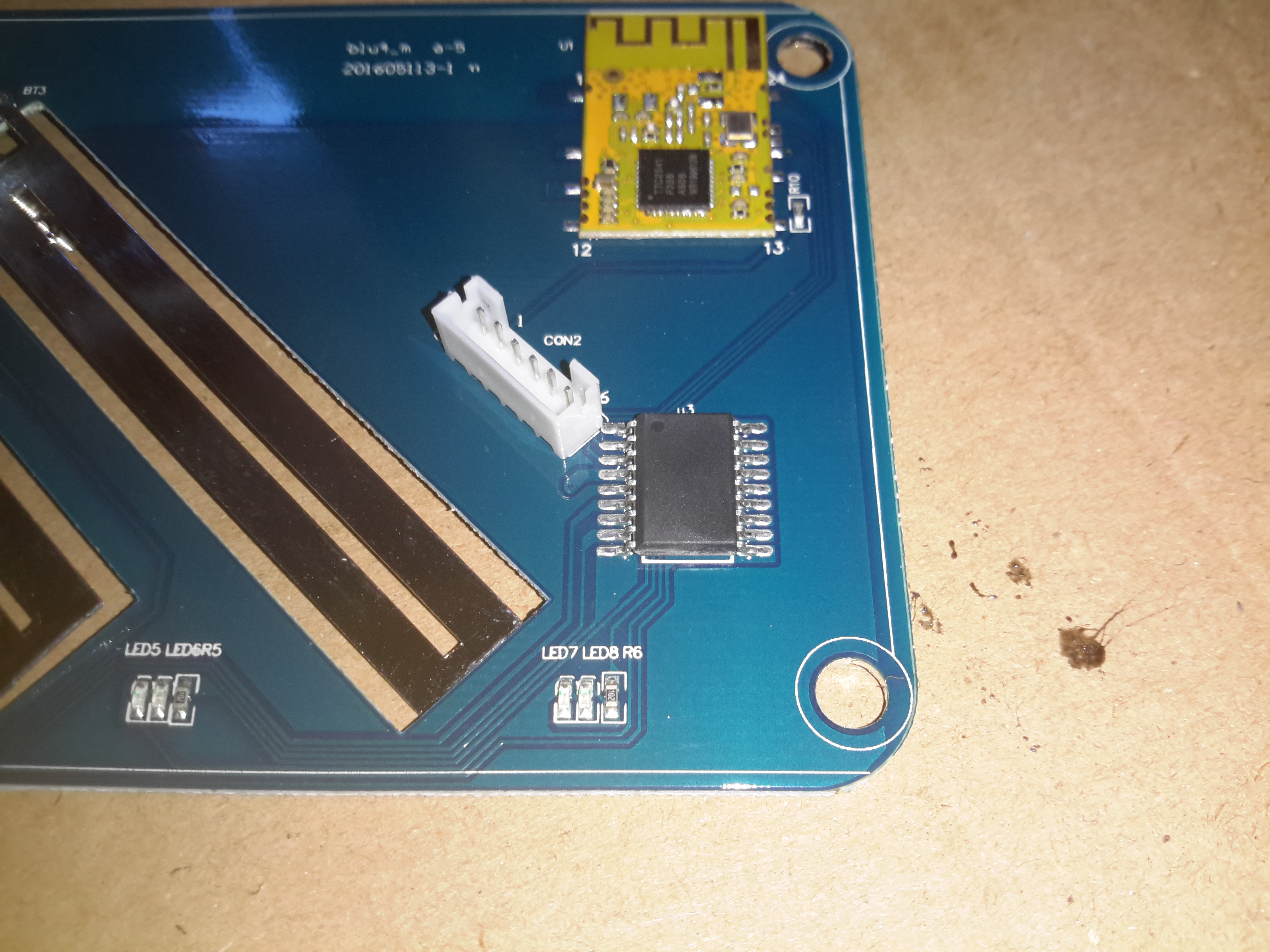
Below the Bluetooth module is yet another completely unmarked IC, the direct link to the BLE interface probably means it’s another microcontroller. The Socket to the left of the IC is the connector for the front panel LCD & button.

LCD PCB
LCD PCB

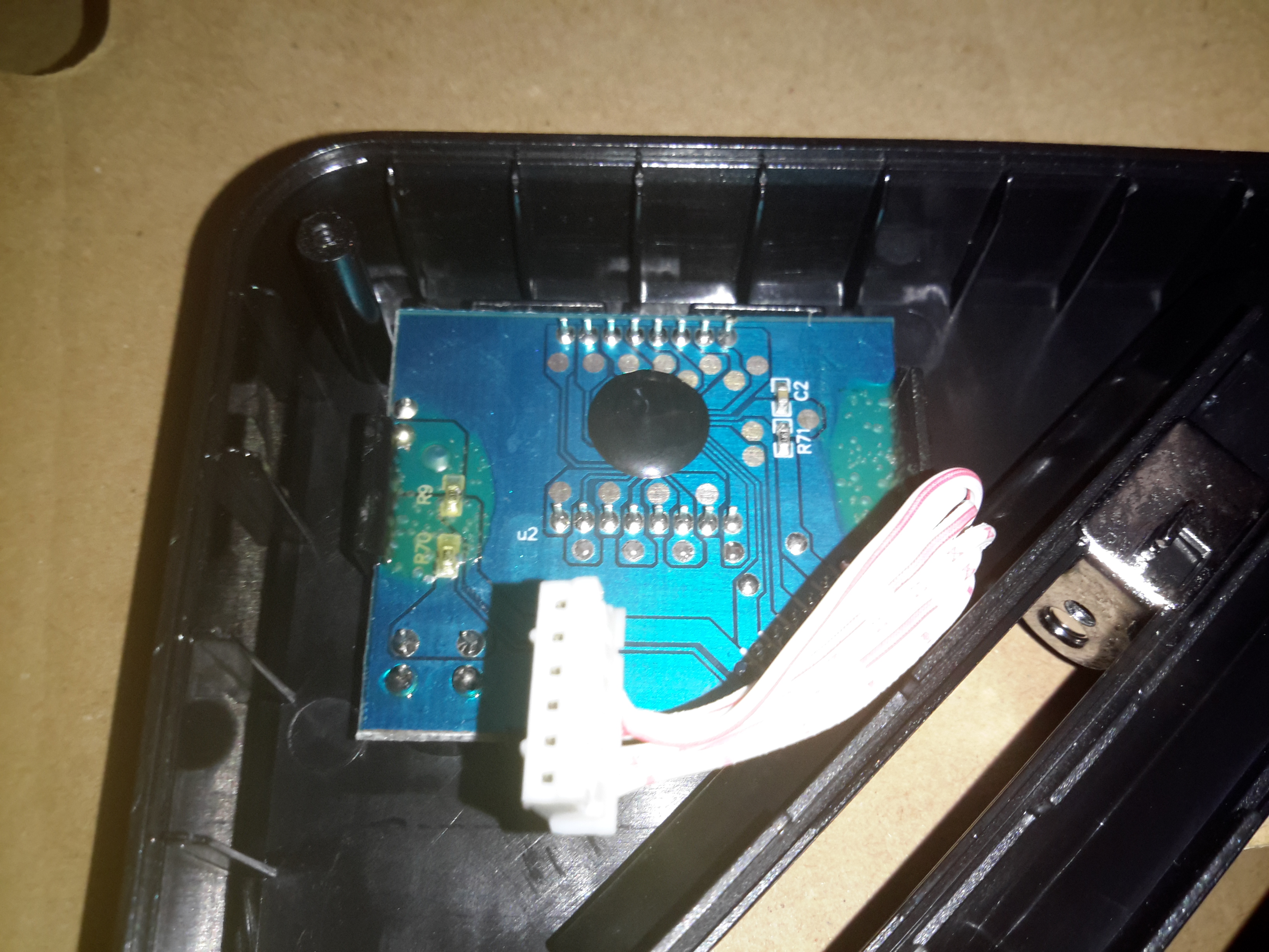
There’s not much to the LCD itself, so I won’t remove this board. The LCD controller is a COB type device, from the number of connections it most likely communicates with the micro via serial.

Posted on Leave a comment

Motorola Cordless DECT Phone Teardown

Motorola DECT Phone
Motorola DECT Phone

Another random teardown from the junk box time!
Here’s an old Motorola DECT landline phone, no use to me as I’ve not used a landline for many years.

Battery Compartment
Battery Compartment

Not much on the back, other than the battery compartment for a pair of AAA rechargables. The base unit contains the charger.

Main PCB
Main PCB

Here’s the main PCB removed from it’s casing. There’s not really much going on, one of the main ICs, which is probably a microcontroller, is a COB device, so no part numbers from there. There’s a row of pads for programming the device at the factory. The RF section is on a dedicated IC, a DE19RF19ZCNC from DSP Group. I couldn’t find much on this part, but it’s one of a range of DECT/VoIP DSP devices.


Base Unit PCB
Base Unit PCB

Inside the base unit is a similar board, just without the keypad. Main microcontroller is again a COB device, the RF IC is under the shield.

Main Chipset
Main Chipset

Removing the shield reveals the same IC as in the handset, only this PCB has a pair of antennas.

Posted on Leave a comment

De La Rue Coin Counting Machine Followup – PSU Oddness

I did a little more digging into the PSU circuitry of the small coin counting machine, and it’s even more strange than I thought!
The part I originally thought was a transformer on the PSU board is in fact a DC-DC converter module!

DC-DC Converter
DC-DC Converter

Here’s the device after desoldering it from the PCB. It turns out that instead of a transformer, it’s an inductor.

Hiding Control Electronics

Underneath is the controller electronics, with an COB controller & the switching transistors are under a protective covering of silicone.

Mains Transformer
Mains Transformer

Driving this whole lot of PSU randomness is the mains transformer, with a secondary voltage of 35v.

The only reason I can think of that the manufacturer went to this much expense with the power supply is stability – a coin counting machine that miscounts due to power supply surges, sags & spikes wouldn’t be very much use. It’s not likely I’ll see anything similar again, unless I manage to get hold of something like medical grade equipment.