Posted on Leave a comment

Motorola Cordless DECT Phone Teardown

Motorola DECT Phone
Motorola DECT Phone

Another random teardown from the junk box time!
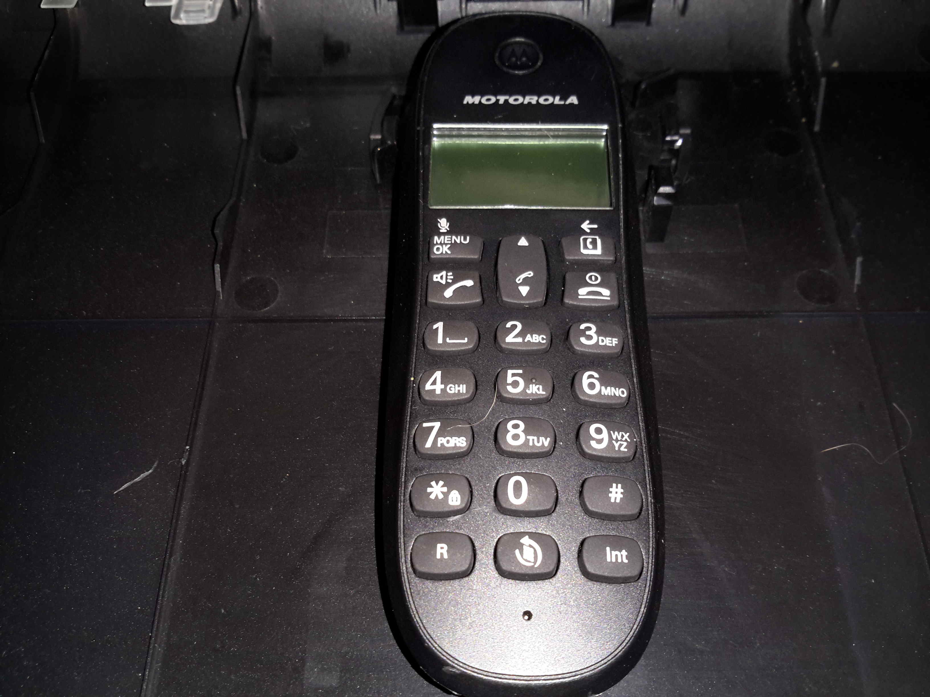
Here’s an old Motorola DECT landline phone, no use to me as I’ve not used a landline for many years.

Battery Compartment
Battery Compartment

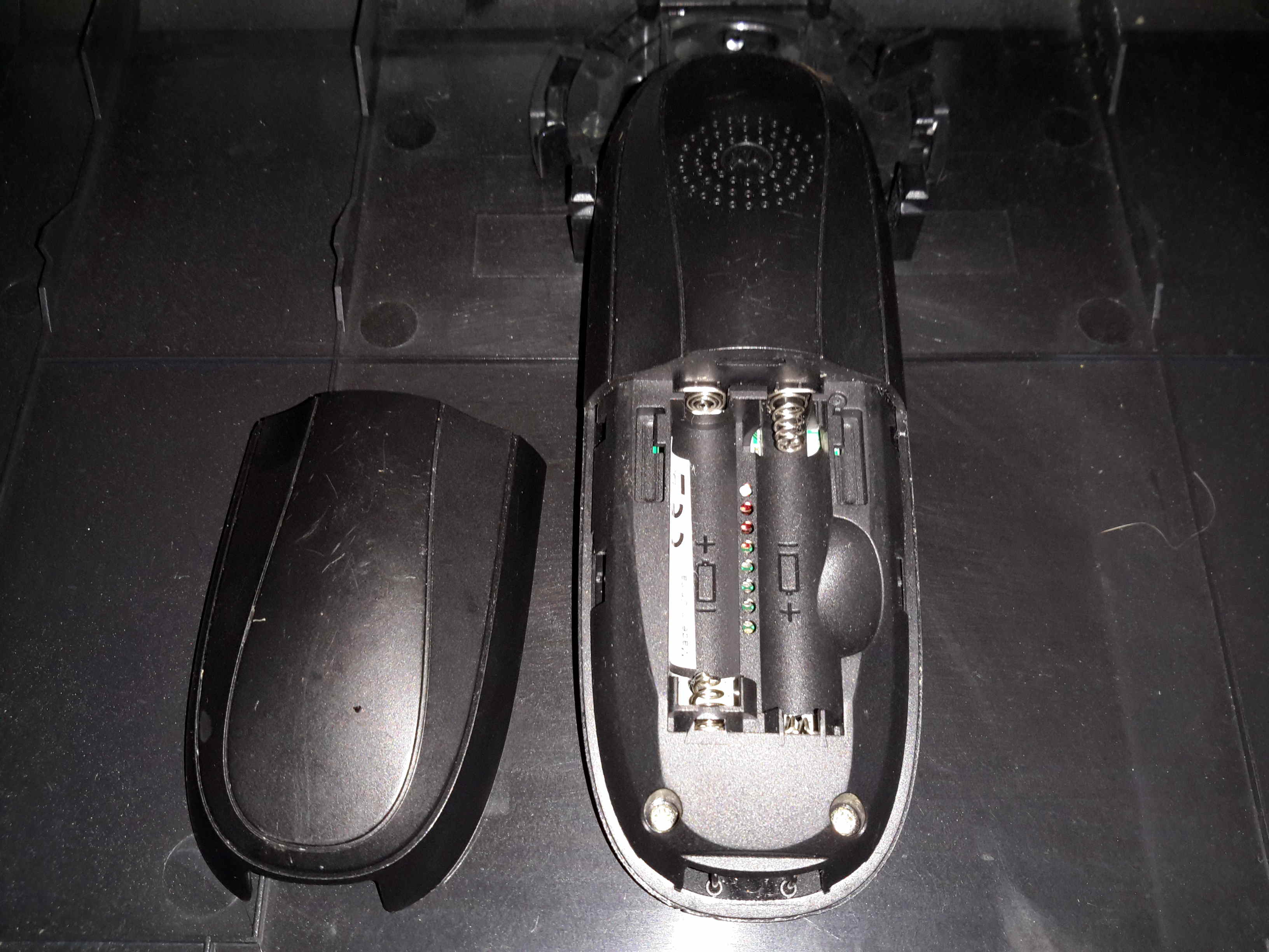
Not much on the back, other than the battery compartment for a pair of AAA rechargables. The base unit contains the charger.

Main PCB
Main PCB

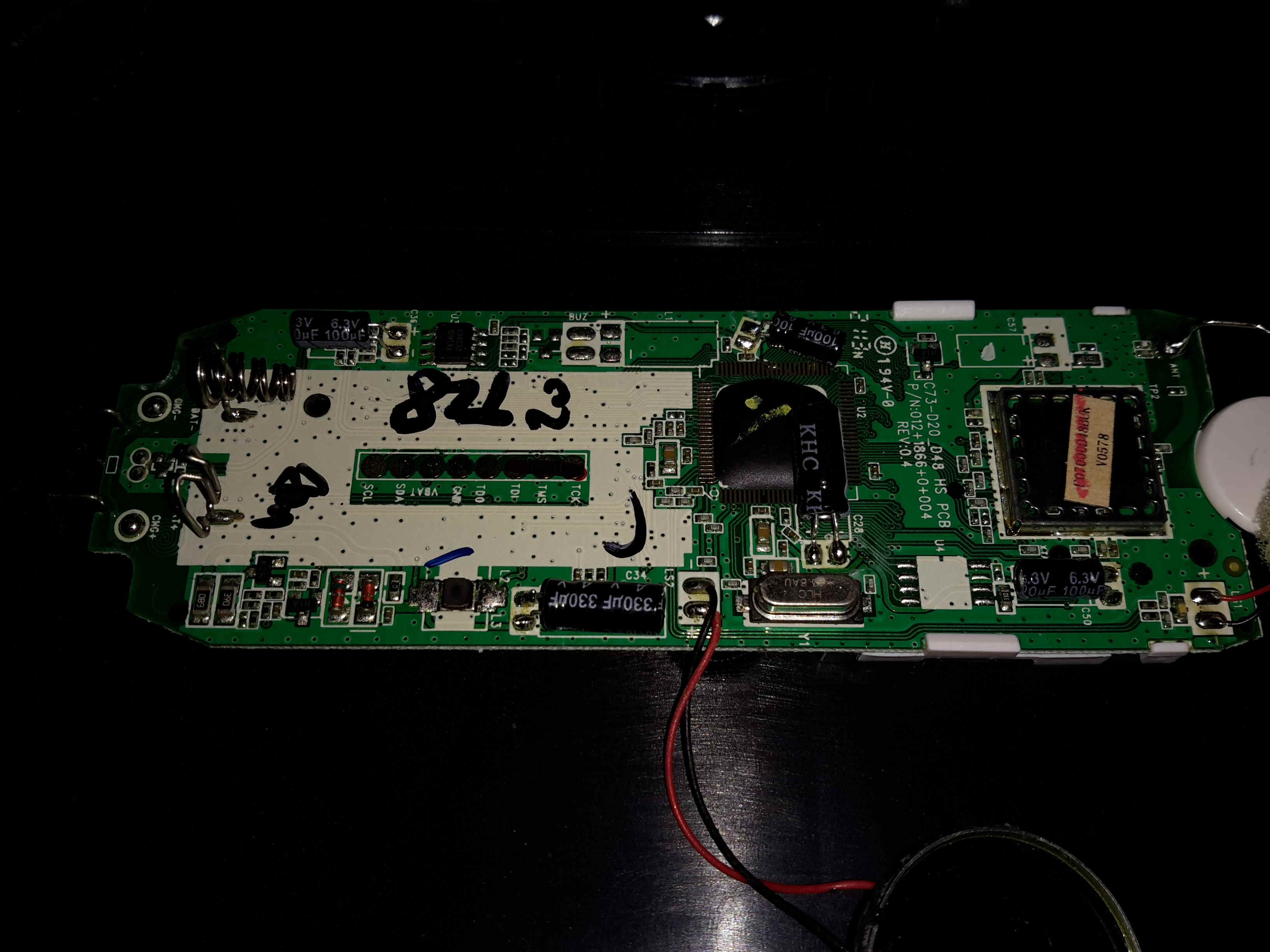
Here’s the main PCB removed from it’s casing. There’s not really much going on, one of the main ICs, which is probably a microcontroller, is a COB device, so no part numbers from there. There’s a row of pads for programming the device at the factory. The RF section is on a dedicated IC, a DE19RF19ZCNC from DSP Group. I couldn’t find much on this part, but it’s one of a range of DECT/VoIP DSP devices.


Base Unit PCB
Base Unit PCB

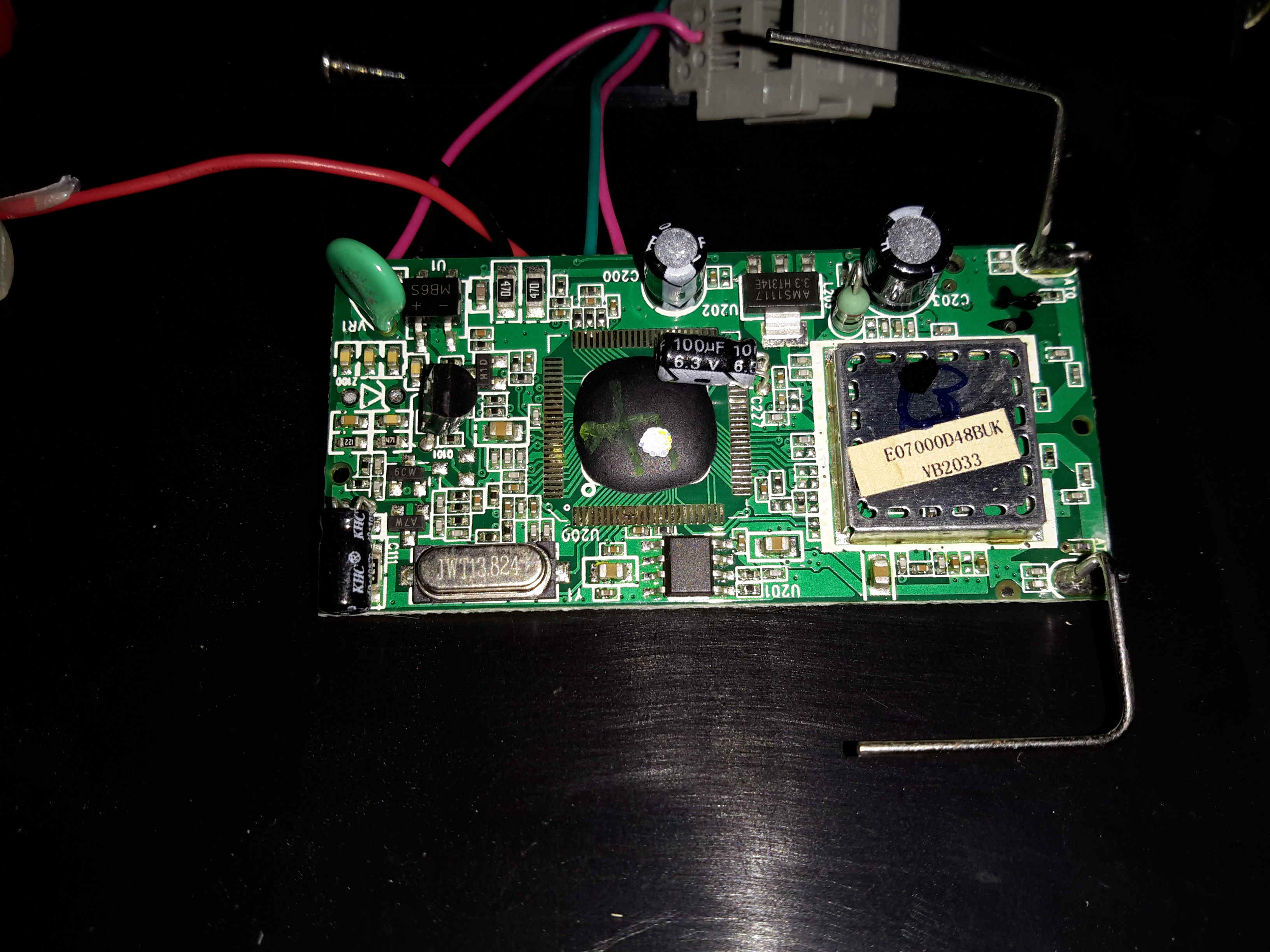
Inside the base unit is a similar board, just without the keypad. Main microcontroller is again a COB device, the RF IC is under the shield.

Main Chipset
Main Chipset

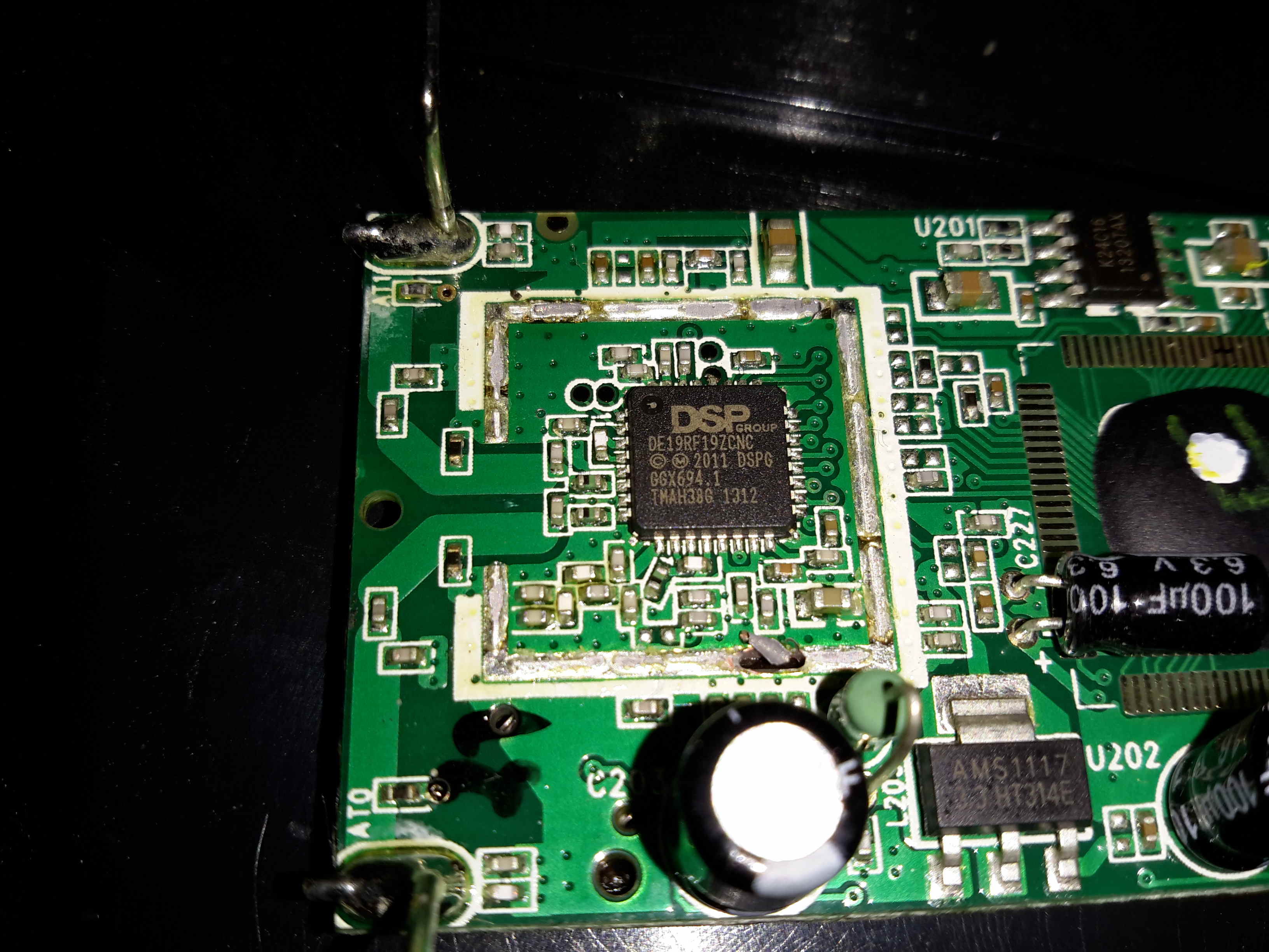
Removing the shield reveals the same IC as in the handset, only this PCB has a pair of antennas.

Posted on 1 Comment

Brightwell Brightstar II BSL4 Dosing System

Overview
Overview
Overview

Here is an old chemical dosing system for industrial washing machines. These units are 4-pump models, with dual pumpheads. The motors are reversed to operate alternate pumps in the same head.

Label
Label

From 2006, this is a fairly old unit, and made in the UK.

CPU Board
CPU Board

Main controller PCB, with interface to the power electronics via the ribbon cable, an external serial port for programming to it’s left. Powered by an ST microcontroller. The LCD is below this board.

PCU & Driver PCBs
PCU & Driver PCBs

Main power supply, sense input & motor driver boards. The PSU outputs +5v, +12v & +24v. The inputs on the lower left connect to the washing machine & trigger the pumps via the programming on the CPU. The motors are driven by L6202 H-Bridge drivers from ST.

Motor Assembly
Motor Assembly

Motor & gearbox assembly on the back of the pumphead. These are 24v DC units with 80RPM gearboxes.

UPDATE:
As it seems to be difficult to find, here is the user manual for this unit:
[download id=”5557″]

Posted on Leave a comment

Southwestern Bell Freedom Phone

Phone
Phone

This is an old cordless landline phone, with dead handset batteries.

Handset Radio Board
Handset Radio Board

Here’s the handset with the back removed. Shown is the radio TX/RX board, underneath is the keyboard PCB with the speaker & mic. All the FM radio tuning coils are visible & a LT450GW electromechanical filter.

Handset Radio Board Bottom

Radio PCB removed from the housing showing the main CPU controlling the unit, a Motorola MC13109FB.

Keypad Board
Keypad Board

The keypad PCB, with also holds the microphone & speaker.

Handset Keypad Board Bottom

Bottom of the keypad board, which holds a LSC526534DW 8-Bit µC & a AT93C46R serial EEPROM for phone number storage.

Base Main Board
Base Main Board

Here’s the base unit with it’s top cover removed. Black square object on far right of image is the microphone for intercom use, power supply section is top left, phone interface bottom left, FM radio is centre. Battery snap for power backup is bottom right.

Power Supply Section

PSU section of the board on the left here, 9v AC input socket at the bottom, with bridge rectifier diodes & main filter capacitor above. Two green transformers on the right are for audio impedance matching. Another LT450GW filter is visible at the top, part of the base unit FM transceiver.

ICs
ICs

Another 8-bit µC, this time a LSC526535P, paired with another AT93C46 EEPROM. Blue blob is 3.58MHz crystal resonator for the MCU clock. The SEC IC is a KS58015 4-bit binary to DTMF dialer IC. This is controlled by the µC.

Base Main Board Bottom

Underside of the base unit Main PCB, showing the matching MC13109FB IC for the radio functions.

Posted on 1 Comment

Co-Op Bank Card Reader

Keypad
Keypad

This is a little security measure you get with Internet Banking with the Co-Op, generates codes to confirm your identity using your bank card. About the size of a pocket calculator, this is the keypad & screen.

Card Slot
Card Slot

The rear of the unit, the card slots into the top, manufactured by Gemalto Digital Security.

Card Contacts
Card Contacts

Outer back cover removed, showing the 8 contacts for the chip on the bank card, the 2 contacts below that switch on power when a card is inserted. Power comes from 2 lithium coin cells in the compartment on the lower left.

PCB Rear
PCB Rear

PCB removed from the casing, showing the internal components. Two large pads at top left are battery connections, while the only IC on the board is the main CPU, under the card connector. 6MHz oscillator & 32Khz crystal on board for processing & timekeeping. LCD screen connection at far right.

Keypad Contacts
Keypad Contacts

Reverse side of the PCB, with the keypad contacts. LCD on right, with programming interface pads at side of keypad.

Posted on Leave a comment

Motorola V360v

Front
Front

Here is a more modern phone, the Motorola V360v. Features include Dual screens, 640×480 VGA camera, full col

our TFT Main LCD, SD-Micro slot.
Here on the back the grey scale LCD can be seen, with the camera lens to the right of the Motorola logo

Keypad
Keypad

Here the phone is opened showing the keypad & the full colour TFT LCD display.

Battery Compartment
Battery Compartment

Here the battery is removed from the unit, showing the SIM connector. The antenna cover is still on at the bottom.

Antenna
Antenna

The antenna cover has been removed in this shot, the antenna is the white section at the bottom, With the loudspeaker & the external antenna connector hidden at the right.

PCB
PCB

Here is the main PCB. Parts from left are the Bluetooth module at the top, supplied by Broadcom, the SD Card socket at the bottom. Main CPU next to that is the Freescale SC29343VKP. Above right of the CPU is the Freescale SC13890P23A Charger, Power & Audio IC. Below is the SIM card socket. Under the main CPU is the Intel Flash memory IC. ICs inside the shields are the RF sections for transmit & receive.

Cover Removed
Cover Removed

Rear of the display unit showing the monochrome LCD. The camera module on the bottom left. Ear speaker on the far right of the unit.

Main LCD
Main LCD

Main colour TFT LCD.

Camera
Camera

Camera module removed from the LCD unit.

Vibra-Motor
Vibra-Motor

The vibration motor attached to one of the LCD looms.

Posted on Leave a comment

Nokia 7110

Front
Front

Another phone from the mid 90s. This is the nokia 7110.

Slider Open
Slider Open

Here the slider is open showing the keypad.

Battery Removed
Battery Removed

Here the battery is removed, a Li-Ion unit.

Battery
Battery

The battery cell & protection circuit removed from the casing.

Rear Of PCB
Rear Of PCB

This is the rear of the PCB removed from the housing. Data & charging ports on the right hand side f the board.

Front Of PCB
Front Of PCB

Front of the PCB with the RF sections at the left hand side & the keypad contacts on the right.

RF Sections
RF Sections

Closeup of the RF sections of the board, big silver rectangular cans are VCO units.

SIM Connector
SIM Connector

Closeup of the top rear section of the PCB, with SIM cnnector, battery contacts, IR tranciever at the far left. Bottom centre is the external antenna connector.

CPU
CPU

The logic section of the board, Large chip is CPU, to right of that is the ROM storing the machine code. Other chips are unknown custom parts.

Mic & Speaker
Mic & Speaker

The Mic & the loudspeaker removed from it’s housing.

LCD
LCD

LCD from the front of the unit, SPI interfaced. Flex PCB also contains the power button, loudspeaker contacts & a temperature sensor.

Scroll Wheel
Scroll Wheel

The scroll wheel removed from the front housing.

Vibra-Motor
Vibra-Motor

Tiny vibration motor removed from the rear housing, alerts the user to a text or phone call.

Posted on Leave a comment

Ericsson GA628

Front
Front

Here is a phone from the mid 90s, the Ericsson GA628. Here visible is the front of the unit with keypad, & single line monochrome LCD for number display.

Battery & Rear
Battery & Rear

Here the battery is removed from the phone, showing the SIM card socket. At the top under the antenna stub is the socket for an external antenna.

Front Removed
Front Removed

Here the front is removed from the phone, PCB on left, rear of keypad on right. Microphone is at bottom of keypad, with speaker at the top. Top right of the PCB is the ringer buzzer, left is shield for RF amplifier.

Main PCB
Main PCB

Here is the back of the main PCB, RF sections on left & centre. Processing & memory on right.

Battery
Battery

This phone had a Ni-Mh battery, before Li-Ion batteries were introduced.

LCD
LCD

The LCD from the front of the phone is shown here. A simple dot matrix single line unit.