Posted on 1 Comment

Brother PT-E300 Industrial Label Machine Teardown

Tape Installed
Tape Installed

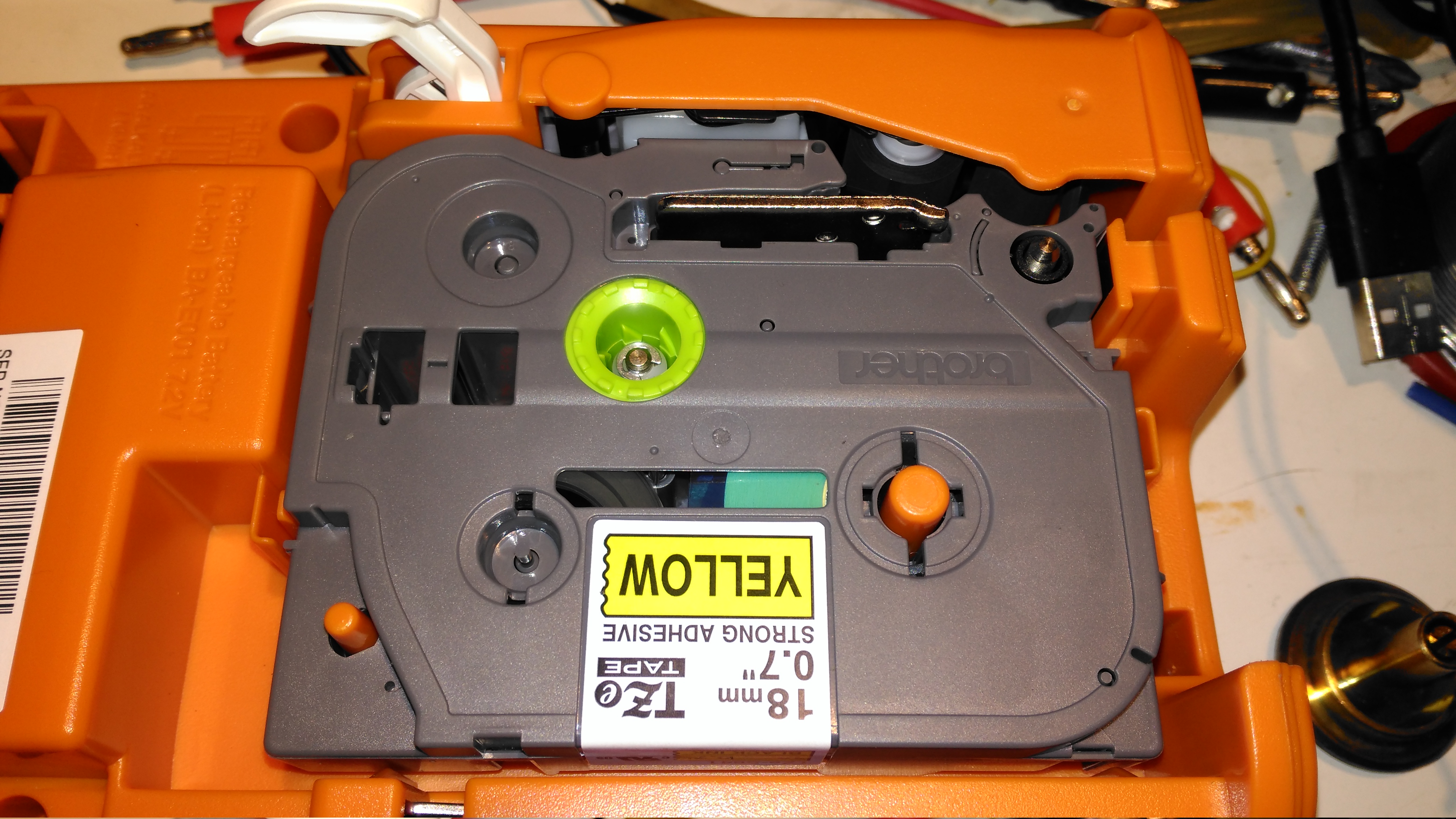
Here a tape is installed in the printer. This unit can handle tape widths up to 18mm. The pinch rollers are operated by the white lever at the top of the image, which engages with the back cover.

Li-Ion Battery
Li-Ion Battery

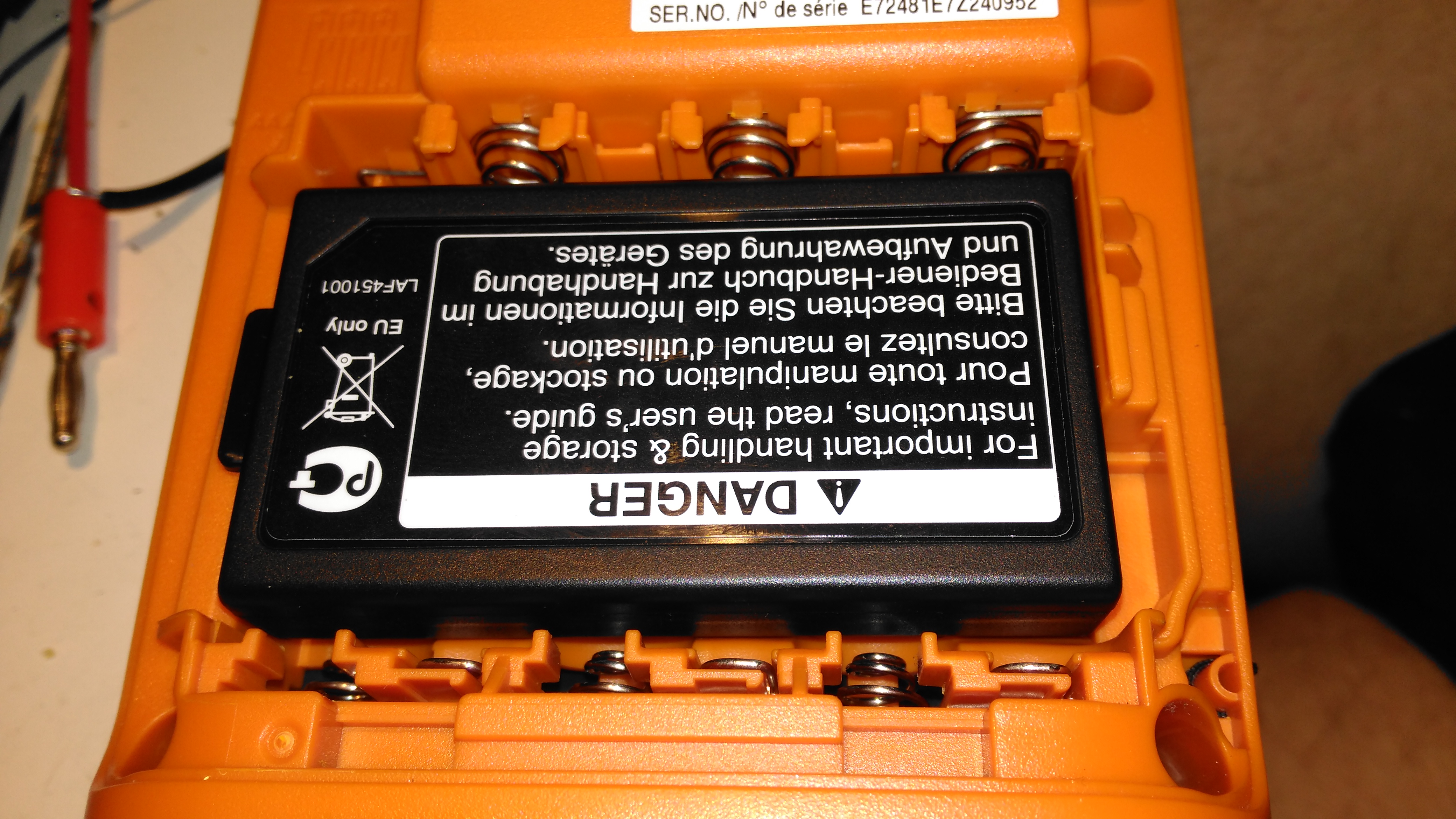
This printer is supplied with a rechargeable battery pack, but AA cells can be used as well. Some of the AA battery terminals can be seen above the battery.

Battery Specs
Battery Specs

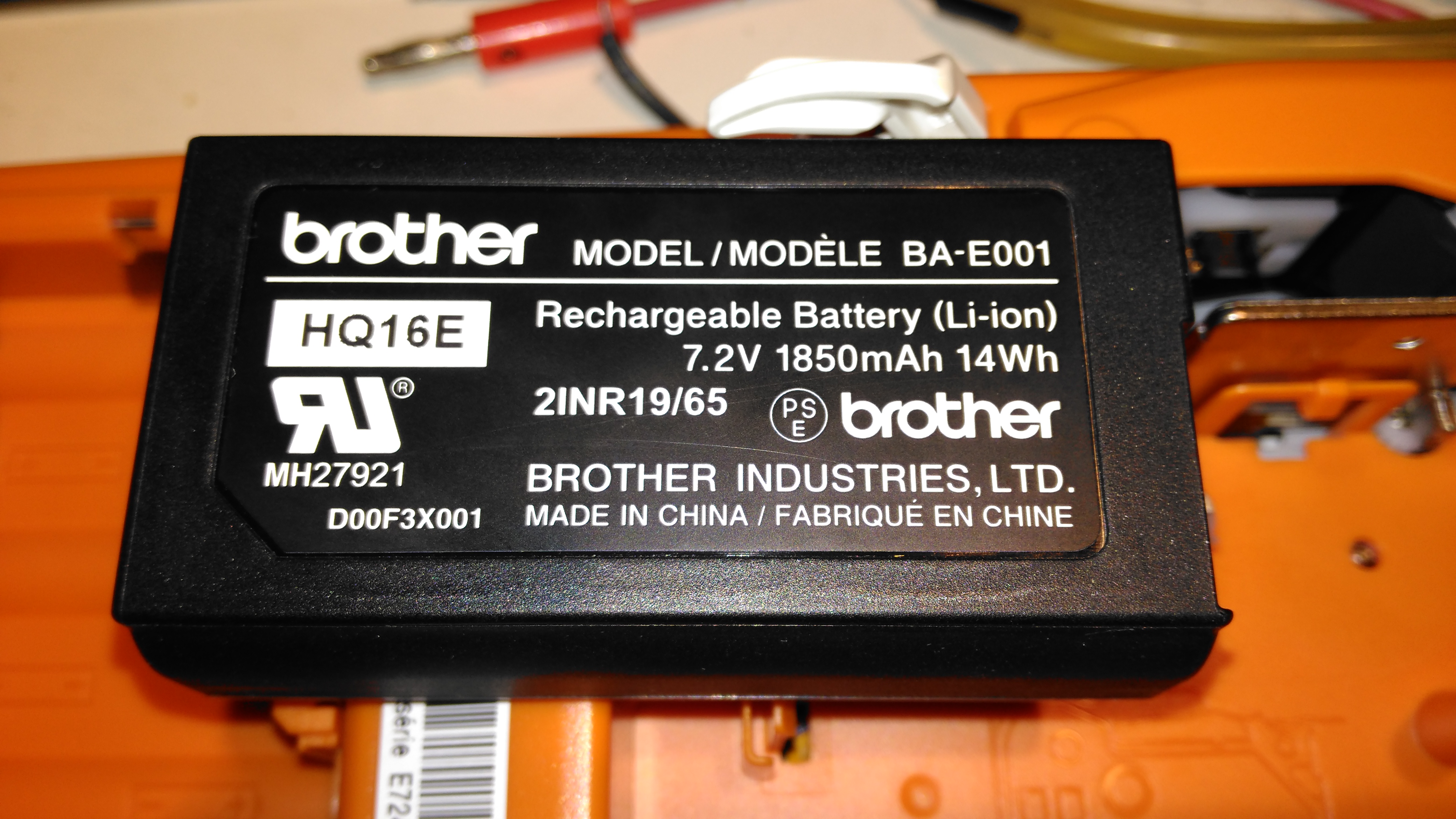
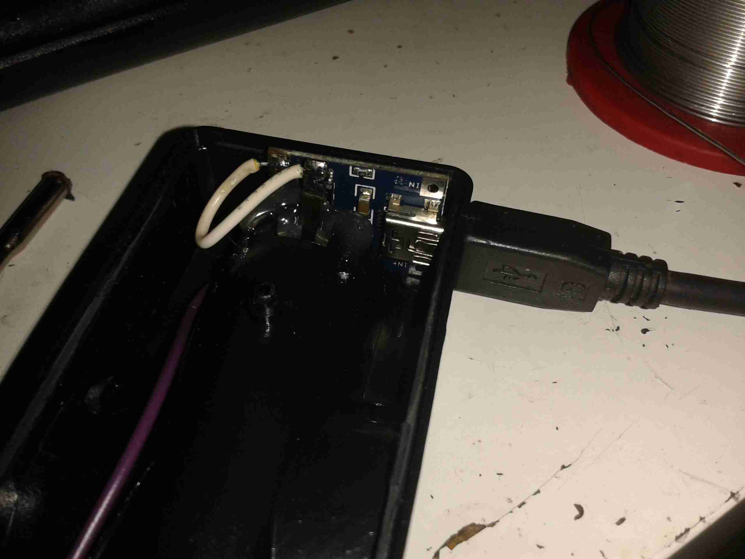
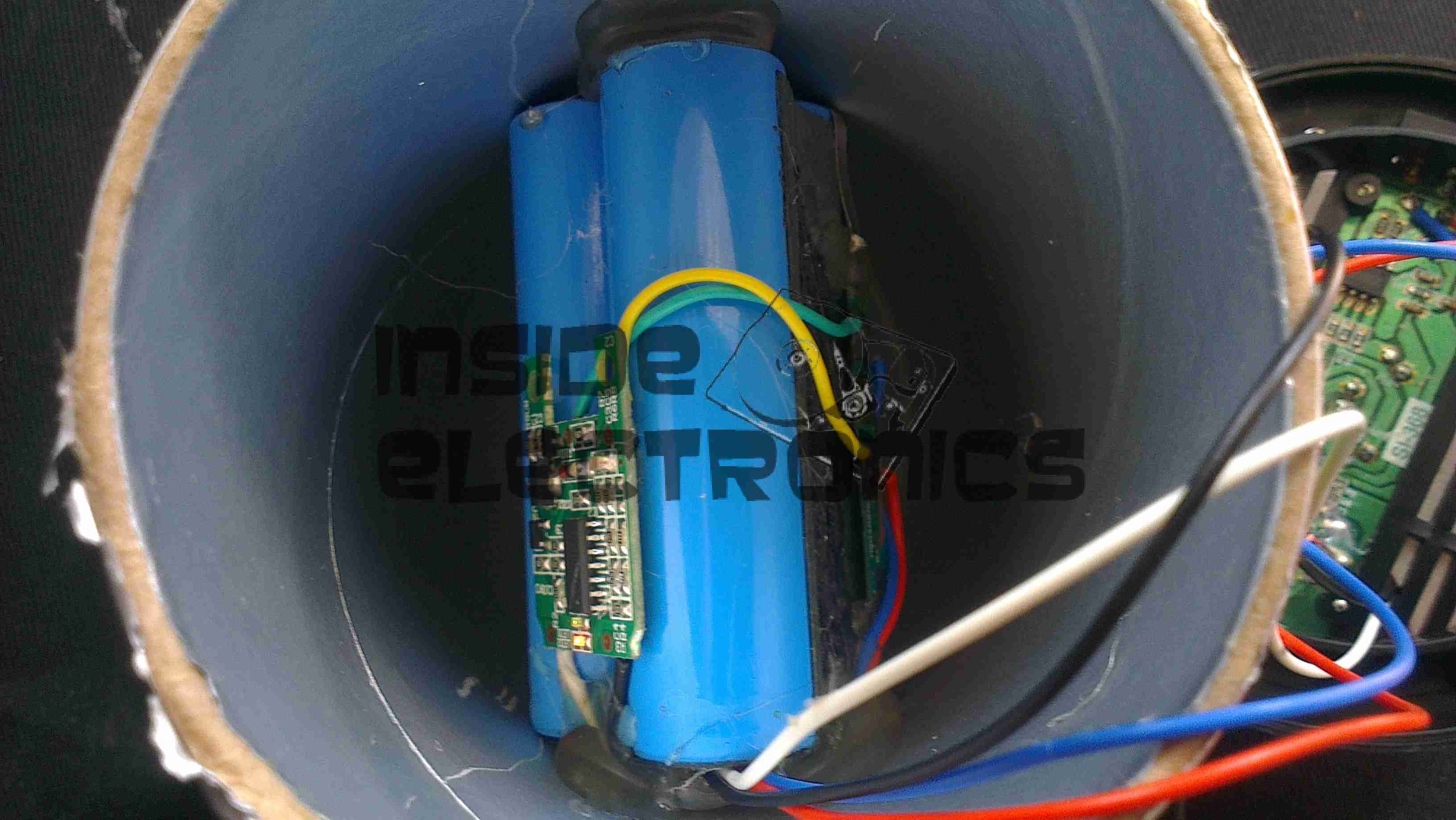
Pretty standard fare for a 2-cell lithium pack. The charging circuitry doesn’t appear to charge it to full voltage though, most likely to get the most life from the pack.

Cartridge Slot
Cartridge Slot

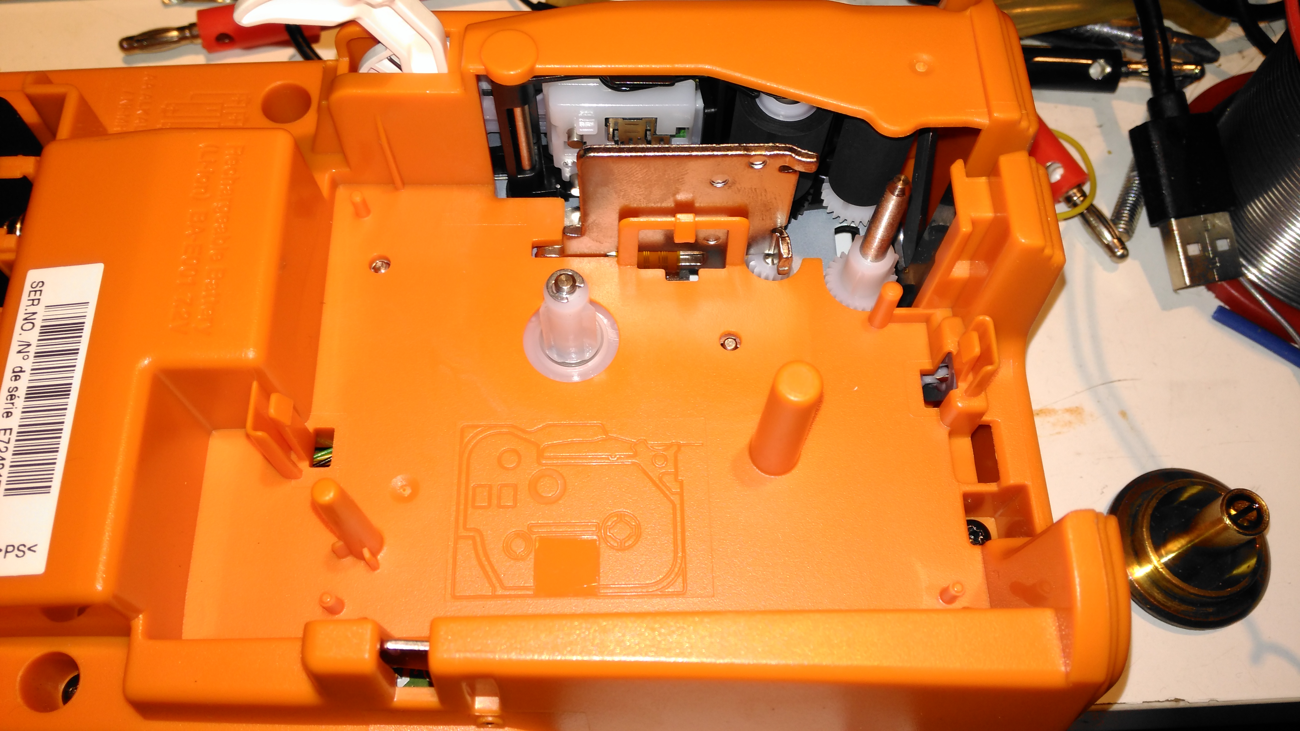
With the cartridge removed, the printer components can be seen. As these cartridges have in effect two rolls, one fro the ribbon & one for the actual label, there are two drive points.

Pinch Rollers & Print Head

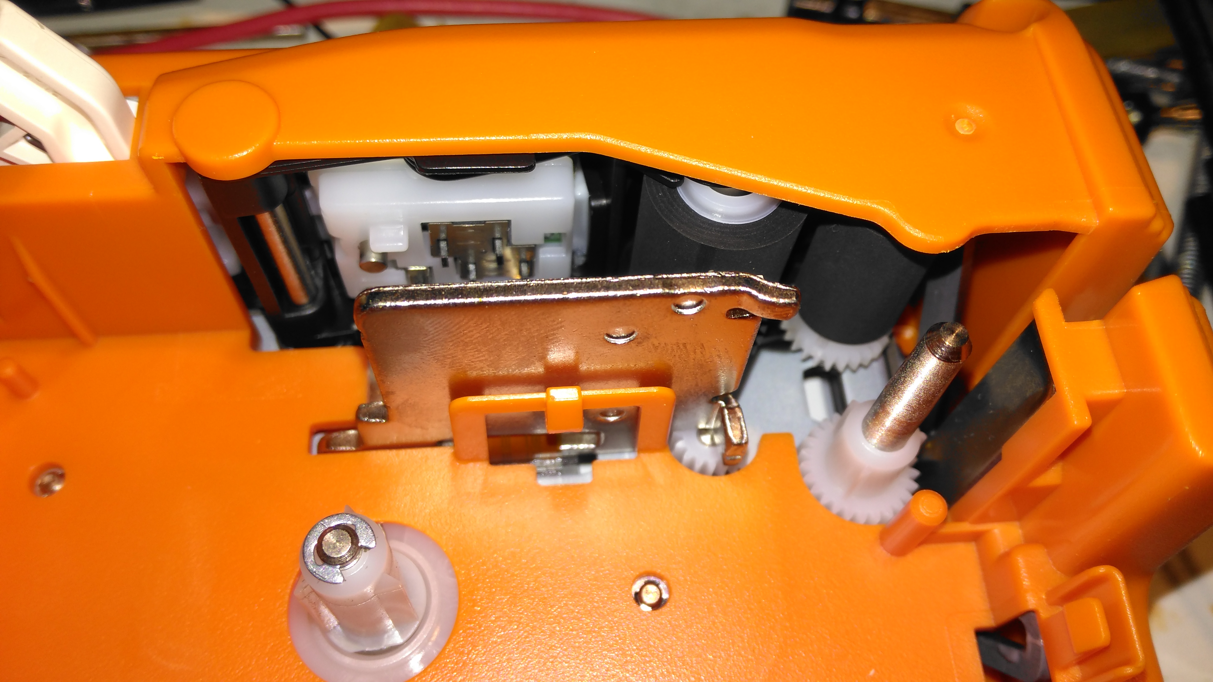
The thermal print head is hidden on the other side of the steel heatsink, while the pinch rollers are on the top right. The plastic piece above the print head heatsink has a matrix of switches that engage with holes in the top of the label cartridge, this is how the machine knows what size of ribbon is fitted.

Mainboard
Mainboard

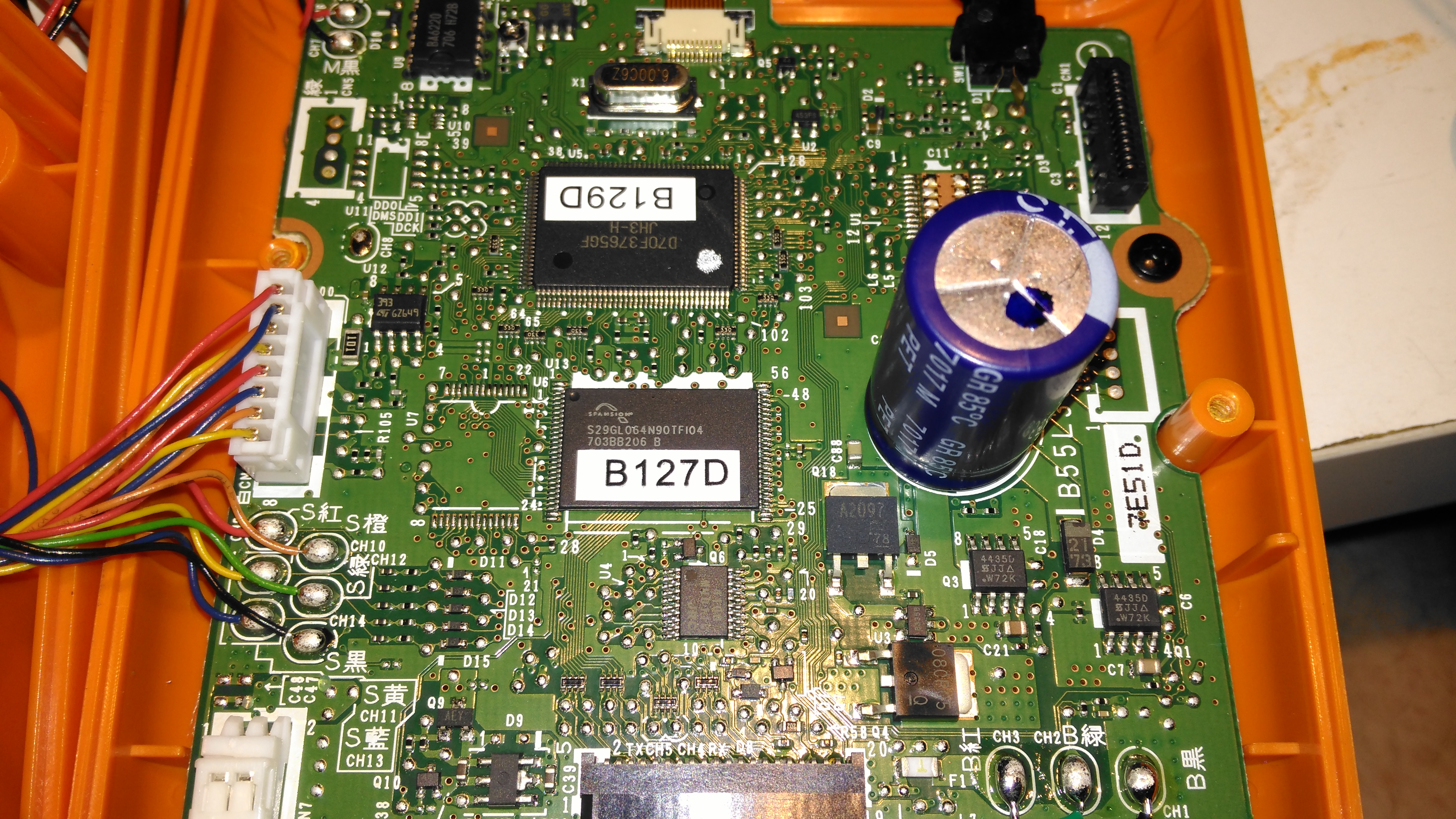
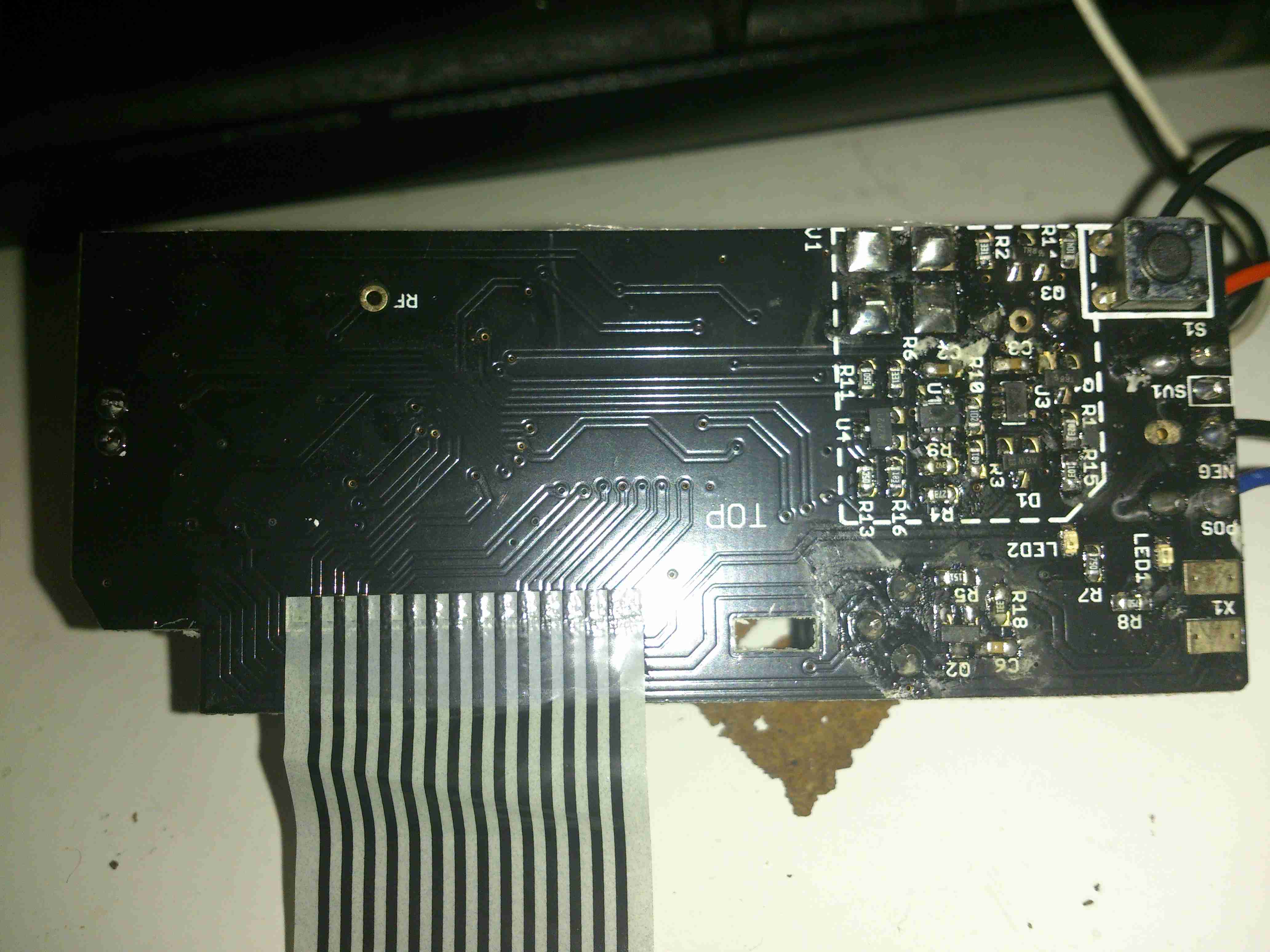
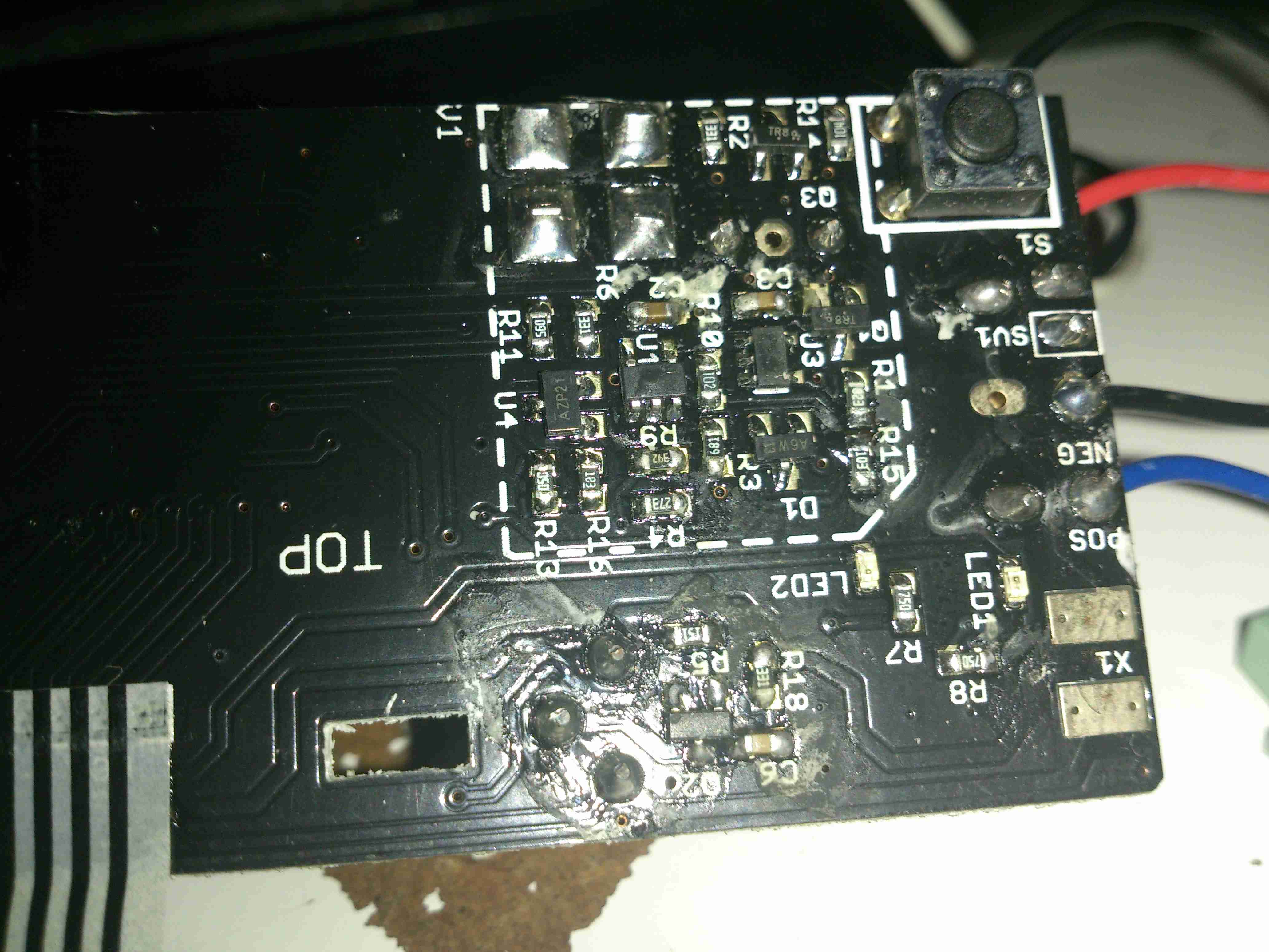
Most of the internal space is taken up by the main board, with the microprocessor & it’s program flash ROM top & centre.

Charger Input
Charger Input

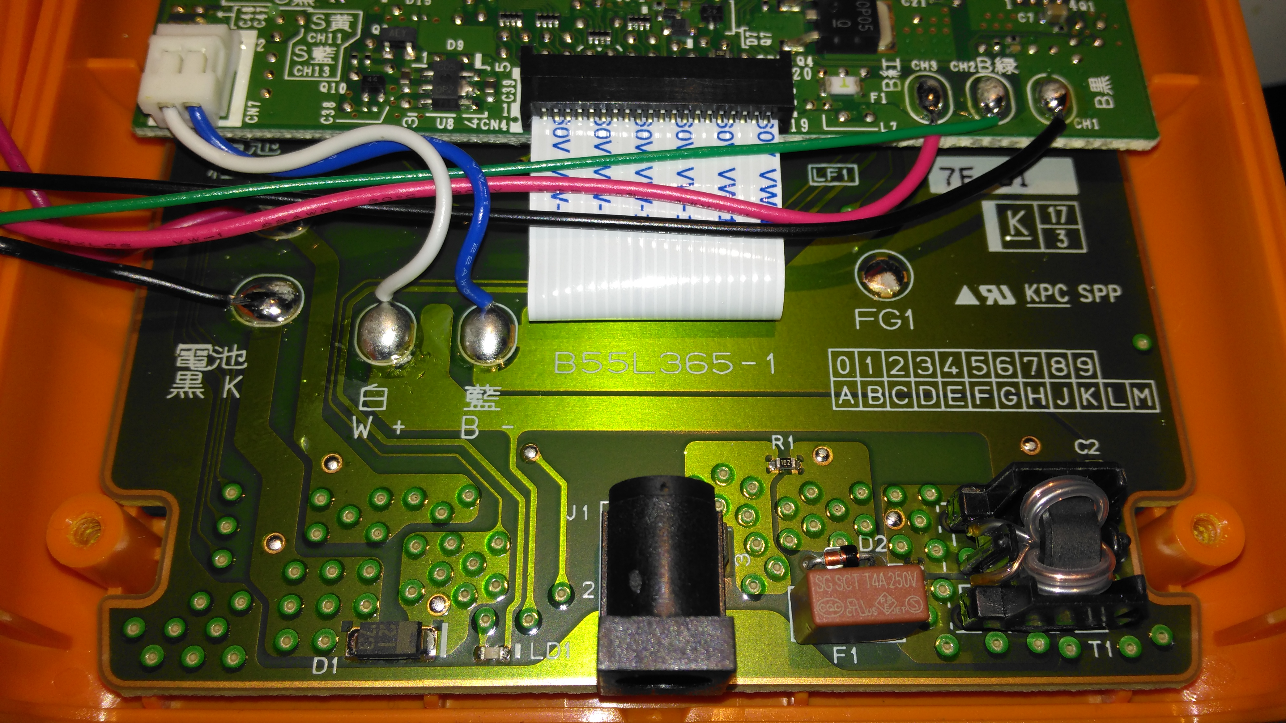
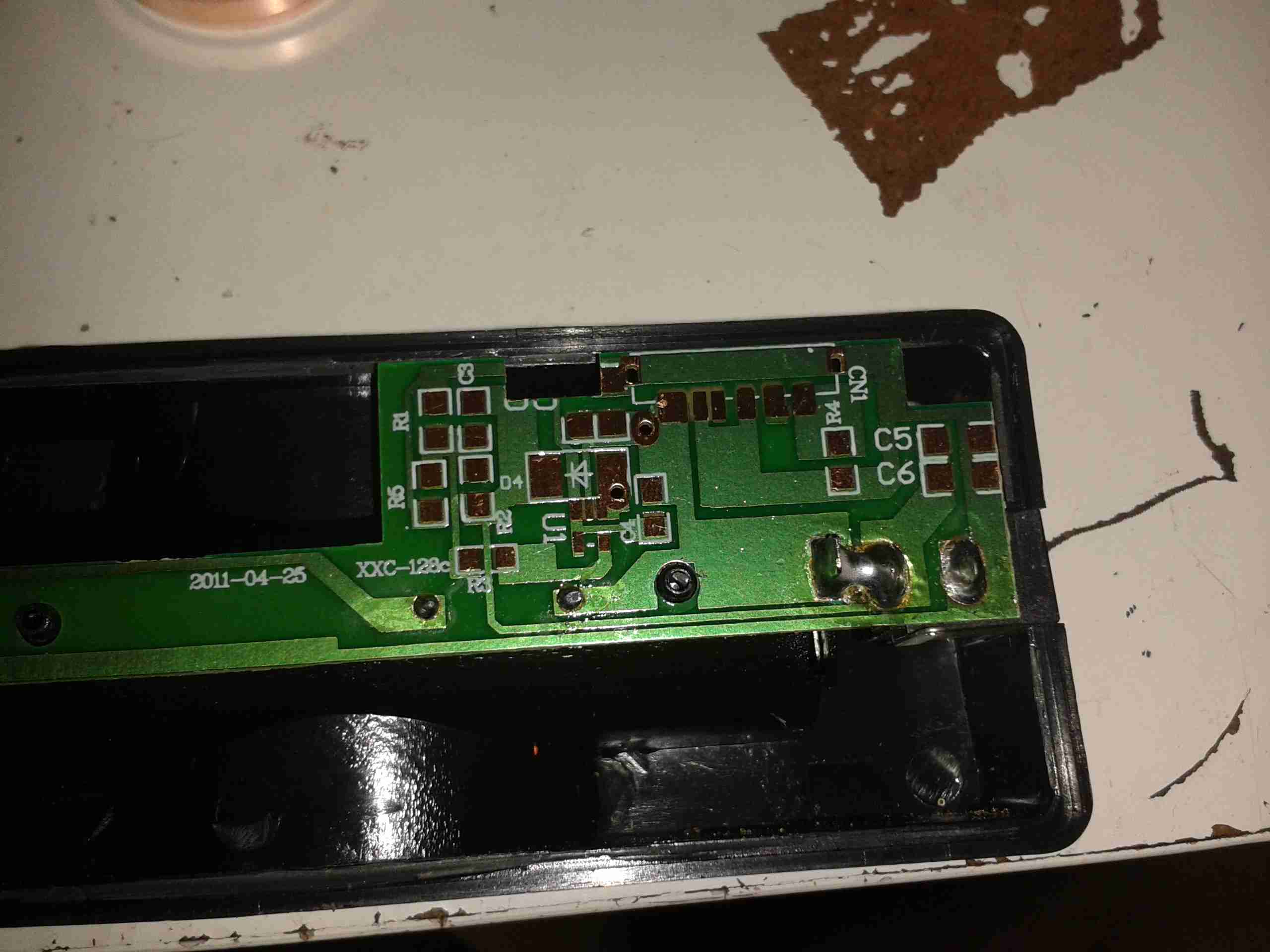
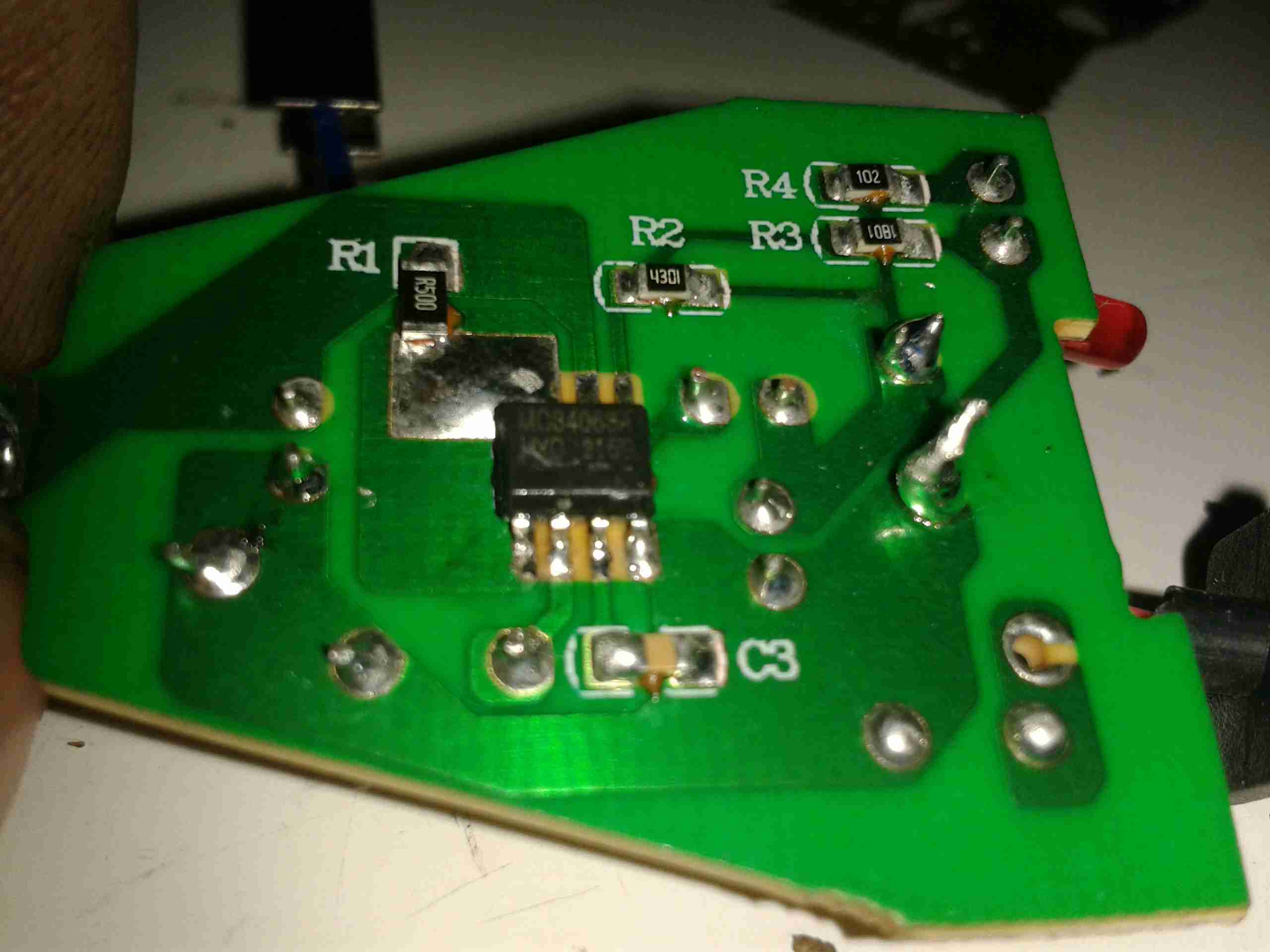
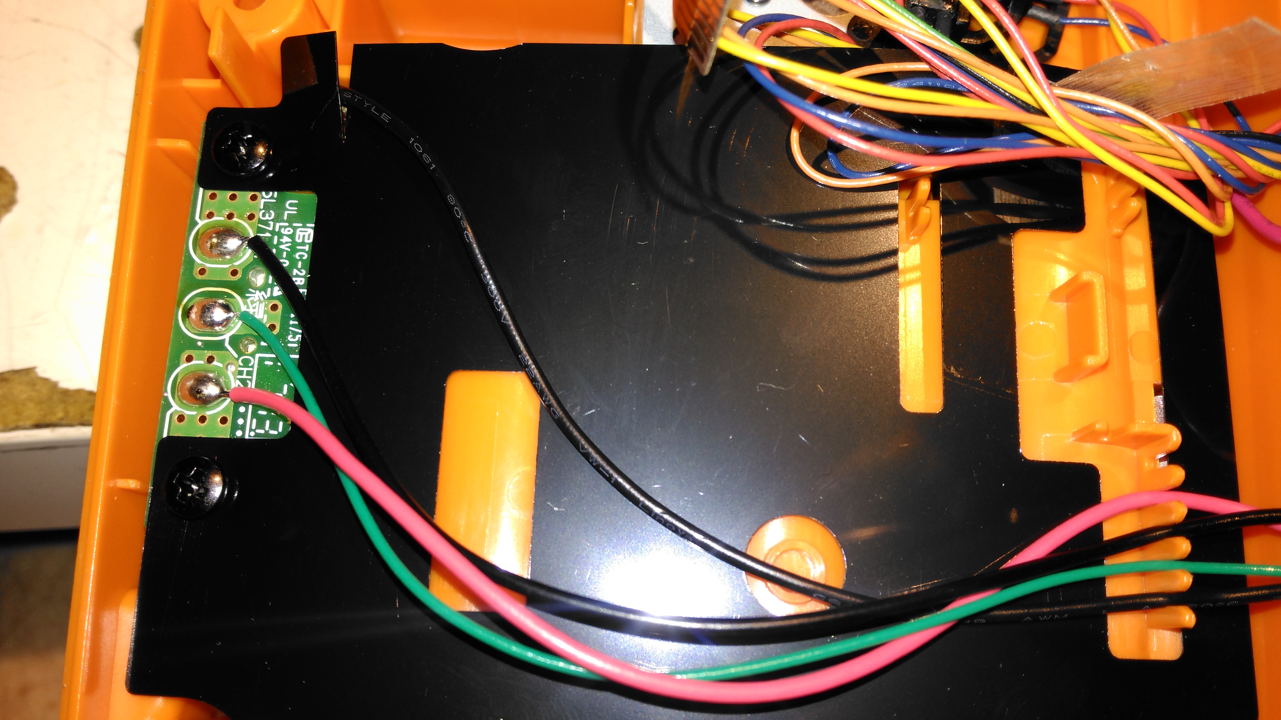
The charger input is located on the keyboard PCB just under the mainboard, which is centre negative, as opposed to 99% of other devices using centre positive, the bastards.

LCD Module
LCD Module

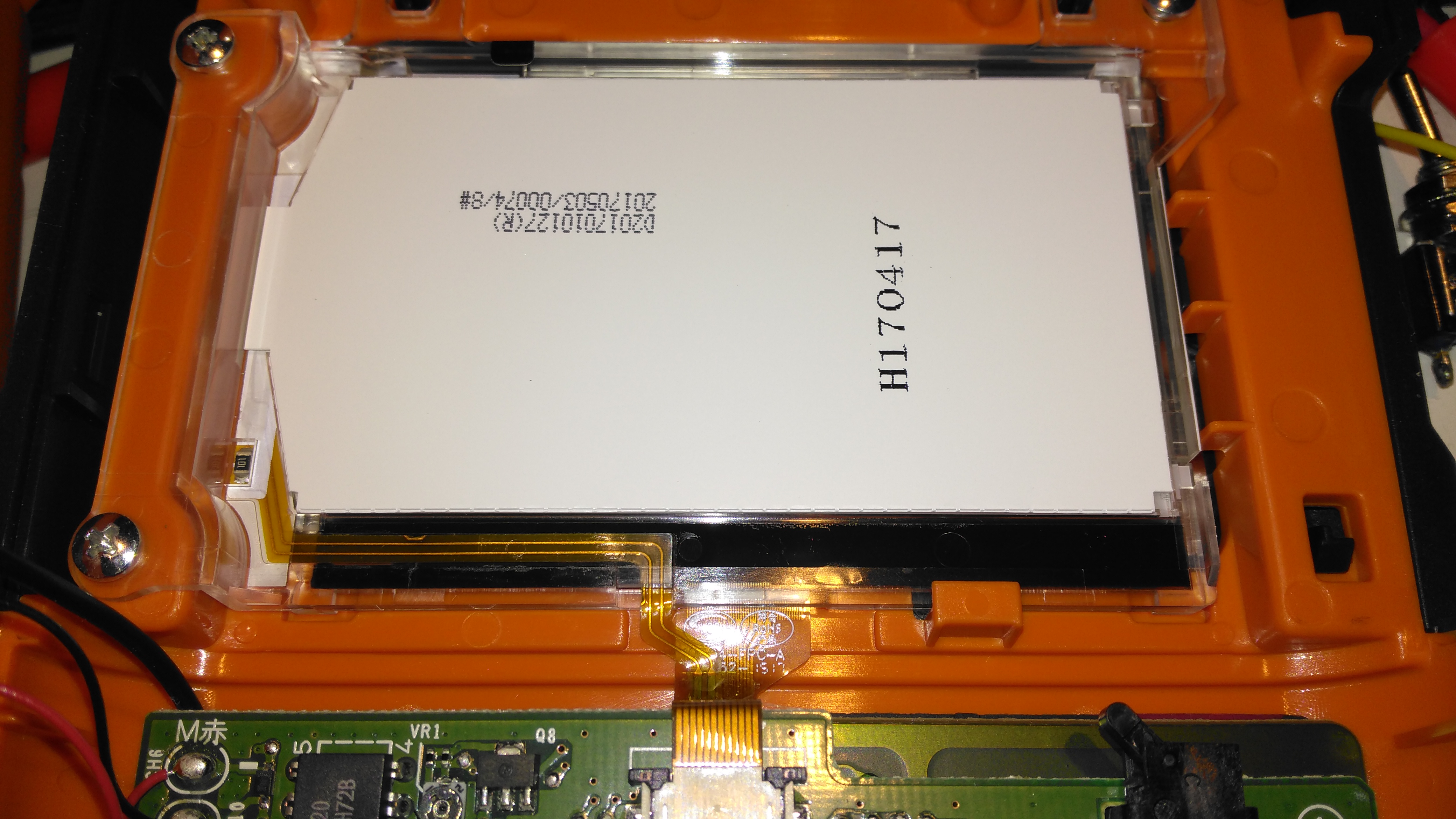
The dot-matrix LCD is attached to the mainboard with a short flex cable, and from the few connections, this is probably SPI or I²C.

Print Mech Drive
Print Mech Drive

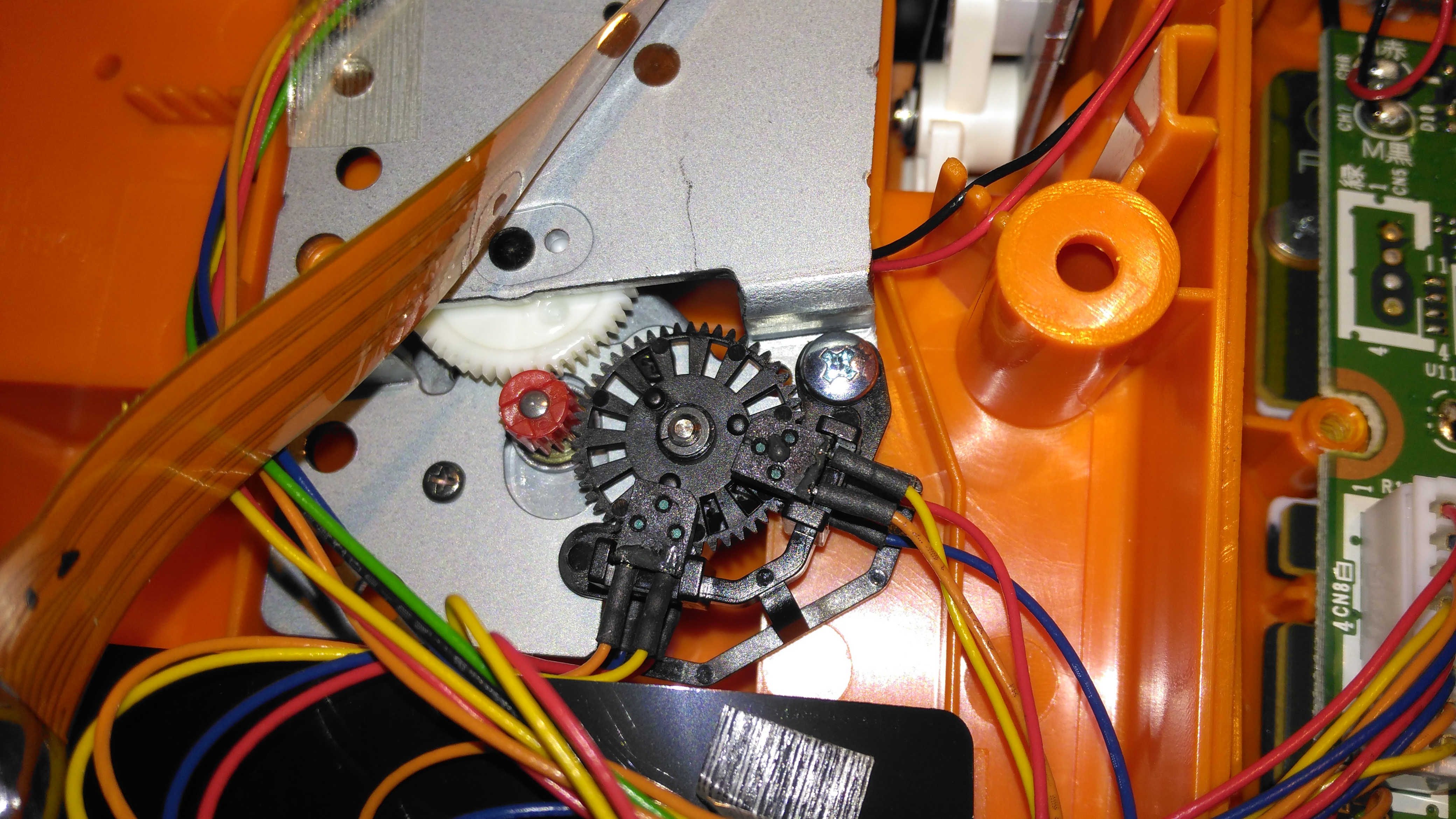
The printer itself is driven by a simple DC motor, speed is regulated by a pair of photo-interrupters forming an encoder on the second gear in the train.

Battery Holder Connections

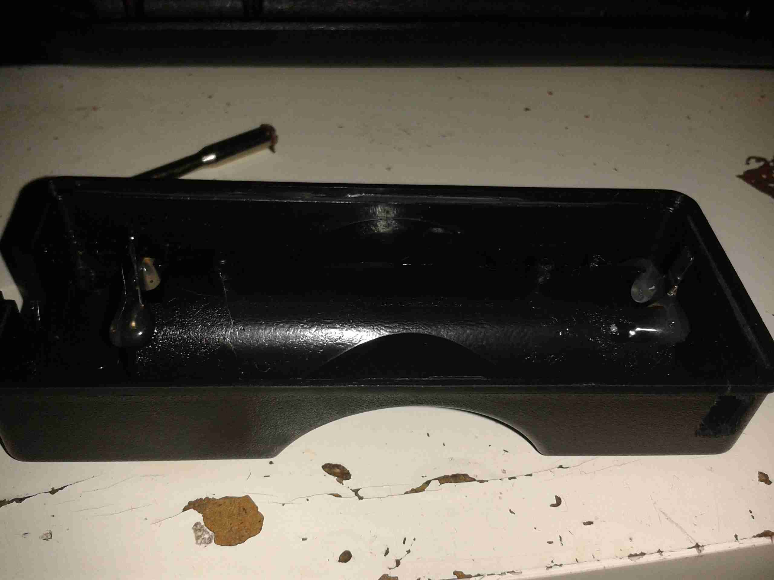
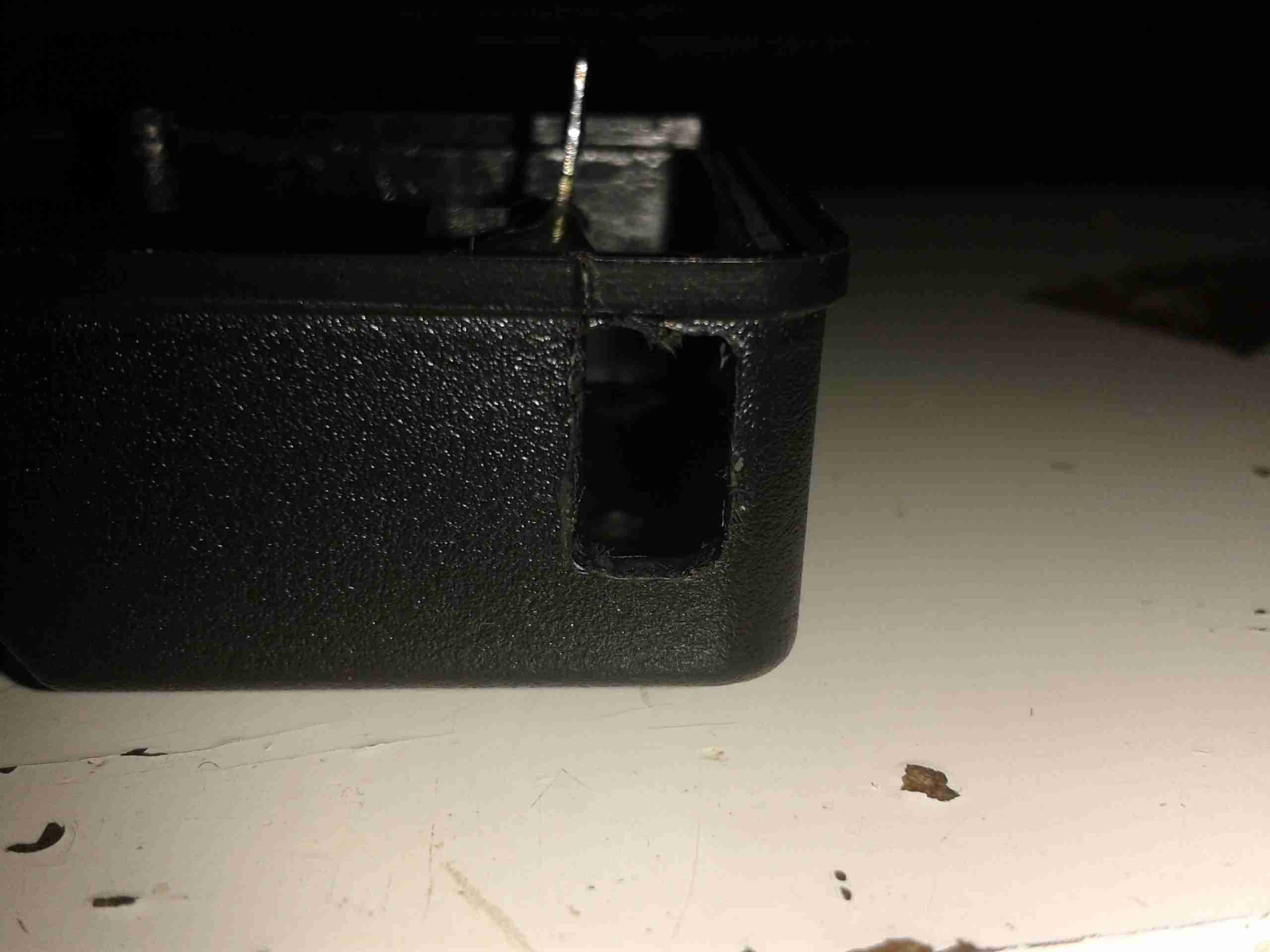
The back case has the battery connections for both the lithium pack & the AA cells, the lithium pack has a 3rd connection, probably for temperature sensing.

Posted on 2 Comments

Fire Angel CO-9D Carbon Monoxide Detector Teardown

Fire Angel CO-9D CO Detector

This detector has now been retired from service since it’s a fair bit out of date. So here’s the teardown!

Information
Information

Unlike older detectors, this unit has a built in battery that never needs replacing during the life of the sensor, so once the unit reaches it’s expiry date it’s just trashed as a whole.

Cover Removed
Cover Removed

4 screws hold the cover on, here’s the internals of the detector. There’s a 3v CR123A LiMnO² cell at the right for power, rated at 1500mAh. A 7 year life is quite remarkable on a single cell!
The sensor is just to the left of the lithium cell, and is of quite unusual construction. Previous CO sensor cells I’ve seen have been small cylinders with a pair of brass pins. This one appears to use a conductive plastic as the connections. These sensors contain H²SO⁴ so they’re a bit hazardous to open.
There are no manufacturer markings on the sensor & I’ve not been able to find any similarly shaped devices, so I’m unsure of it’s specifications.
The alarm sounder is on the left, the usual Piezo disc with a resonator to increase the loudness.

Microcontroller
Microcontroller

The brains of the device are provided by a Microchip PIC16F914 microcontroller. This is a fairly advanced device, with many onboard features, and NanoWatt™ technology, standby power consumption is <100nA according to Microchip’s Datasheet. This would explain the incredible battery life.
The choke just at the right edge of the photo is actually a transformer to drive the Piezo sounder at high voltage.

PCB Reverse
PCB Reverse

Here’s the PCB with the LCD frame removed. Not much to see on the this side, the silence/test button top right & the front end for the sensor.

Sensor Front End Amplifier

Here’s a closer look at the front end for the CO sensor cell itself. I haven’t been able to decode the SMT markings on the SOT packages, but I’m guessing that there’s a pair of OpAmps & a voltage reference.

Posted on Leave a comment

Maplin LED Torch Charger Replacement

In my previous post, I mentioned I’d be replacing the factory supplied charging gear with something that actually charges lithium chemistry cells correctly.

Charging Base
Charging Base

Here’s the base as supplied, with an indicator LED on the right hand side. This LED indicates nothing other than power being applied to the charging base. It’s just connected across the power input with a resistor. This also means that any battery left in the charger while it’s unplugged will discharge itself through this LED over time. Great design there China!

PCB Removed
PCB Removed

Here I’ve removed the PCB – there’s no need for it to be taking up any space, as it’s just a complete waste of copper clad board in the first place. The battery tabs have been desoldered & hot snot used to secure them into the plastic casing.

USB Hole
USB Hole

The charger modules I use are USB powered, so a small hole has been routed out in the casing to allow access to the port.

Charging Module
Charging Module

Here the charging module has been installed & wired to the battery tabs. Output is now a nice 4.18v, and will automatically stop charging when the cell is full.
Safety has been restored!

73s for now folks!

Posted on Leave a comment

Maplin 3W LED Torch Charger Fail

A member of the family recently bought one of these torches from Maplin electronics, and the included chargers for the 18650 lithium-ion cells leave a lot to be desired.

Torch
Torch

Here’s what’s supplied. The torch itself is OK – very bright, and a good size. Me being cynical of overpriced Chinese equipment with lithium batteries, I decided to look in the charging base & the cigar-lighter adaptor to see if there was any actual charging logic.

Charger
Charger

Answer – nope. Not a single active component in here. It’s just a jack connected to the battery terminals. There’s all the space there to fit a proper charging circuit, but it’s been left out to save money.

OK then, is it inside the cigarette lighter adaptor?

Lighter Adaptor
Lighter Adaptor

Nope. Not a single sign of anything resembling a Lithium-Ion charger IC. There’s a standard MC34063A 1.5A Buck converter IC on the bottom of the PCB, this is what’s giving the low voltage output for the torch.

Charger Bottom
Charger Bottom

Here’s the IC – just a buck converter. The output voltage here is 4.3v. This is higher than the safe charging voltage of a lithium ion cell, of 4.2v.

The cells supplied are “protected” versions, having charge/discharge protection circuitry built onto the end of the cell on a small PCB, this makes the cell slightly longer than a bare 18650, so it’s easy to tell them apart.
The manufacturers in this case are relying on that protection circuit on the cell to prevent an overcharge condition – this isn’t the purpose they’re designed for, and charging this way is very stressful for the cells. I wouldn’t like to leave one of these units charging unattended, as a battery explosion might result.

More to come shortly when I build a proper charger for this torch, so it can be recharged without fearing an alkali metal fire!

73s for now folks!

Posted on Leave a comment

Pringles Speaker Modifications

USB Charging Port
USB Charging Port

These speakers are available free from Pringles, with two packs bought. Normally running on 3x AAA cells, I have made modifications to include a high capacity Li-Ion battery & USB charging.

18650 Battery
18650 Battery

New battery is 3x 18650 Li-Ion cells in parallel, providing ~6600mAh of capacity. These are hot glued inside the top of the tube under the speaker, with the charging & cell protection logic.
The battery charging logic is salvaged from an old USB eCig charger, these are single cell lithium chargers in a small form factor ideal for other uses. Charging current is ~450mA.

Amplifier Board
Amplifier Board

The cells are connected to the same points as the original AAA cells, with the other pair of wires going into the top of the device to connect to the MicroUSB charging port.

The amplifier in this is a LM4871 3W Mono amplifier IC, connected to a 6Ω 1W speaker.
The other IC on the board is unidentifiable, but provides the flashing LED function to the beat of the music.


Posted on 1 Comment

Co-Op Bank Card Reader

Keypad
Keypad

This is a little security measure you get with Internet Banking with the Co-Op, generates codes to confirm your identity using your bank card. About the size of a pocket calculator, this is the keypad & screen.

Card Slot
Card Slot

The rear of the unit, the card slots into the top, manufactured by Gemalto Digital Security.

Card Contacts
Card Contacts

Outer back cover removed, showing the 8 contacts for the chip on the bank card, the 2 contacts below that switch on power when a card is inserted. Power comes from 2 lithium coin cells in the compartment on the lower left.

PCB Rear
PCB Rear

PCB removed from the casing, showing the internal components. Two large pads at top left are battery connections, while the only IC on the board is the main CPU, under the card connector. 6MHz oscillator & 32Khz crystal on board for processing & timekeeping. LCD screen connection at far right.

Keypad Contacts
Keypad Contacts

Reverse side of the PCB, with the keypad contacts. LCD on right, with programming interface pads at side of keypad.