Another random teardown from the junk box time!
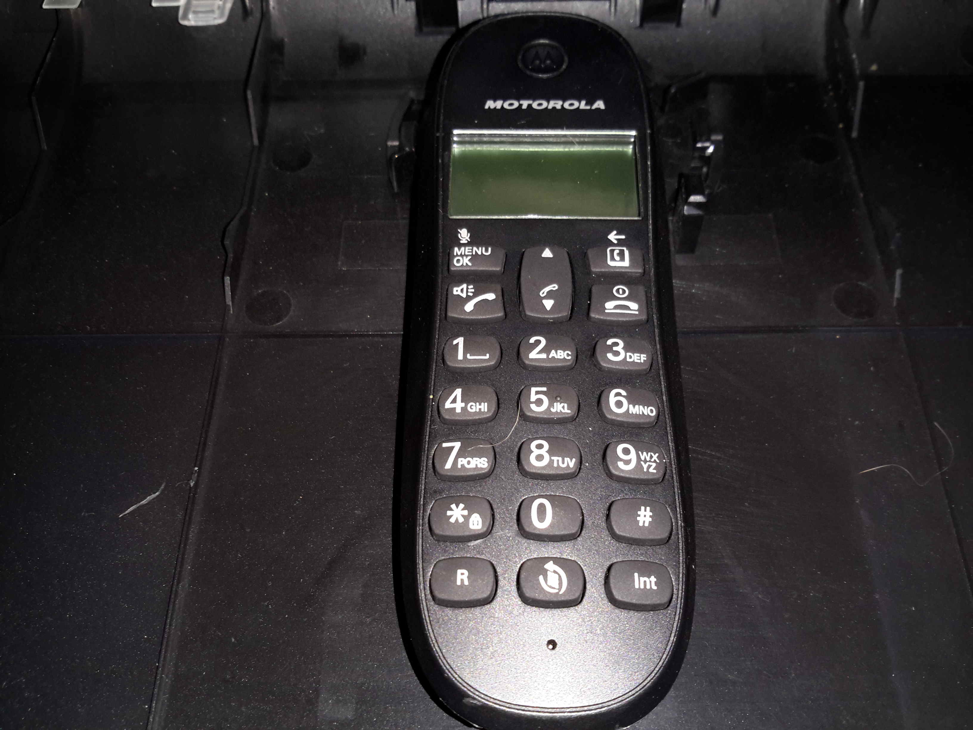
Here’s an old Motorola DECT landline phone, no use to me as I’ve not used a landline for many years.
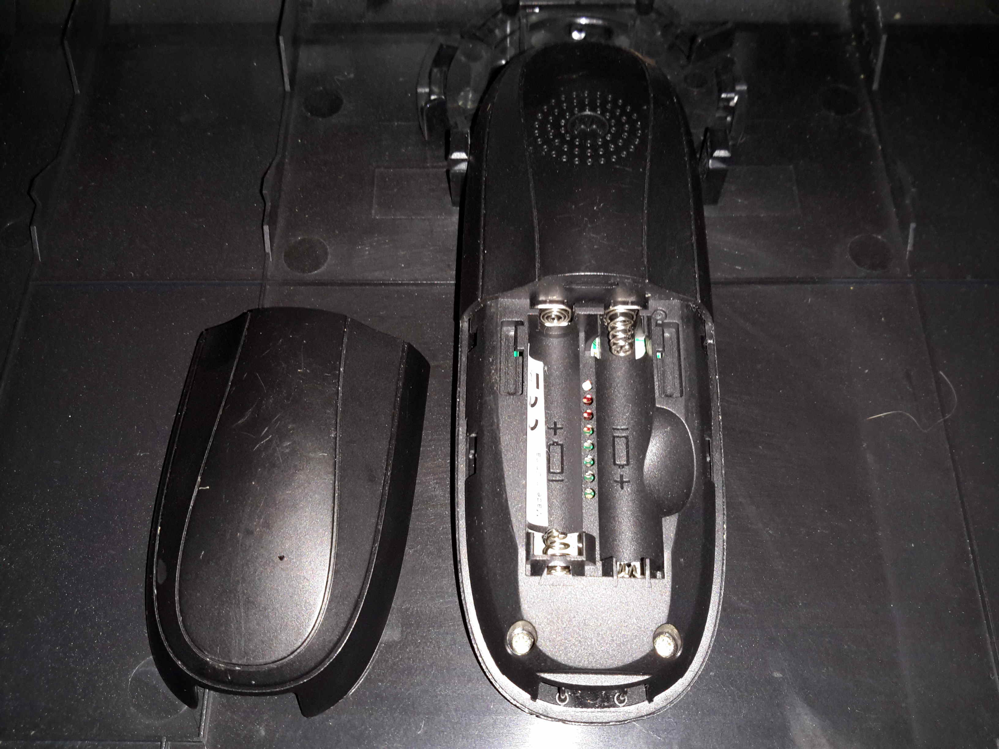
Battery Compartment
Not much on the back, other than the battery compartment for a pair of AAA rechargables. The base unit contains the charger.
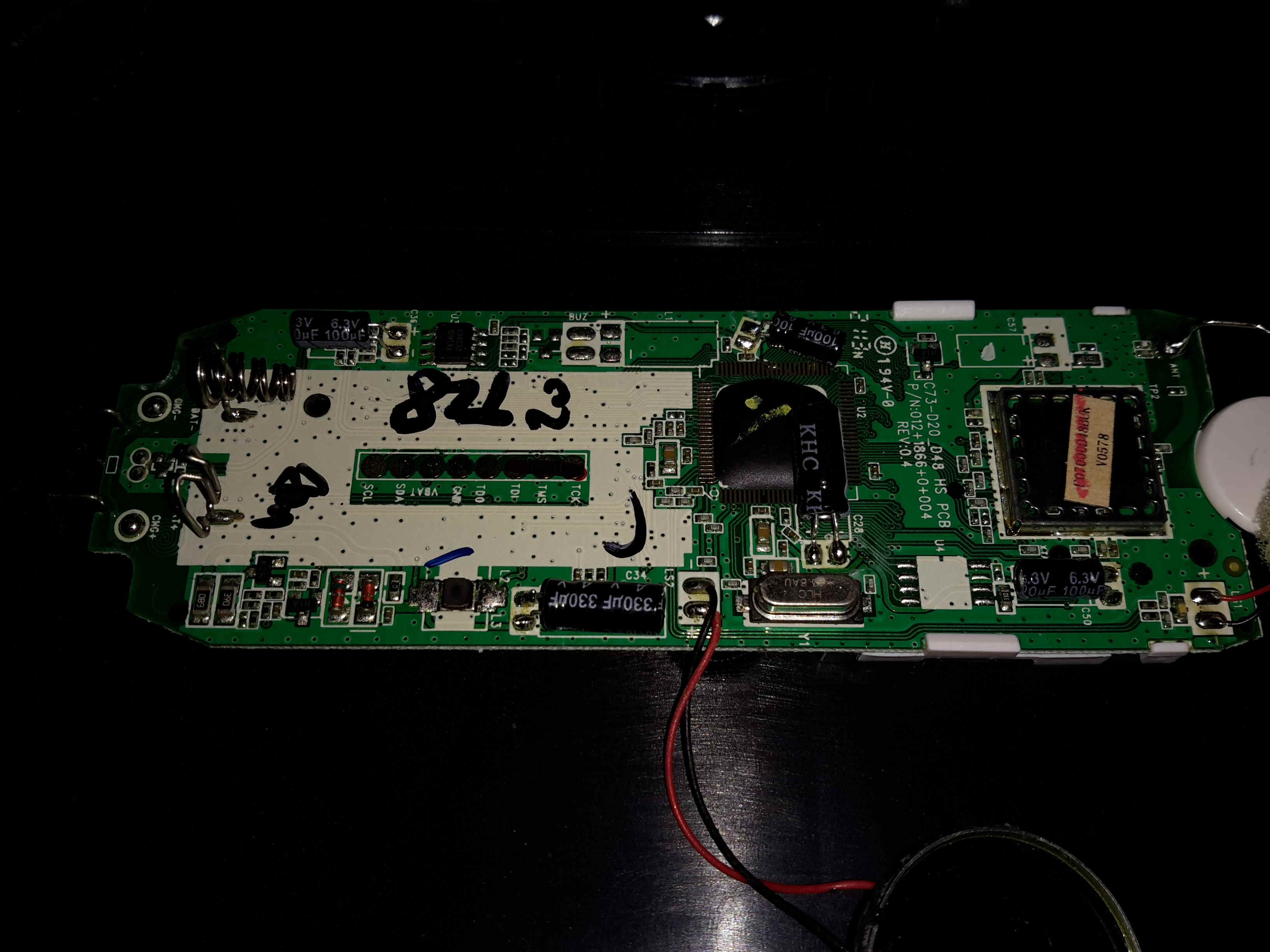
Main PCB
Here’s the main PCB removed from it’s casing. There’s not really much going on, one of the main ICs, which is probably a microcontroller, is a COB device, so no part numbers from there. There’s a row of pads for programming the device at the factory. The RF section is on a dedicated IC, a DE19RF19ZCNC from DSP Group. I couldn’t find much on this part, but it’s one of a range of DECT/VoIP DSP devices.
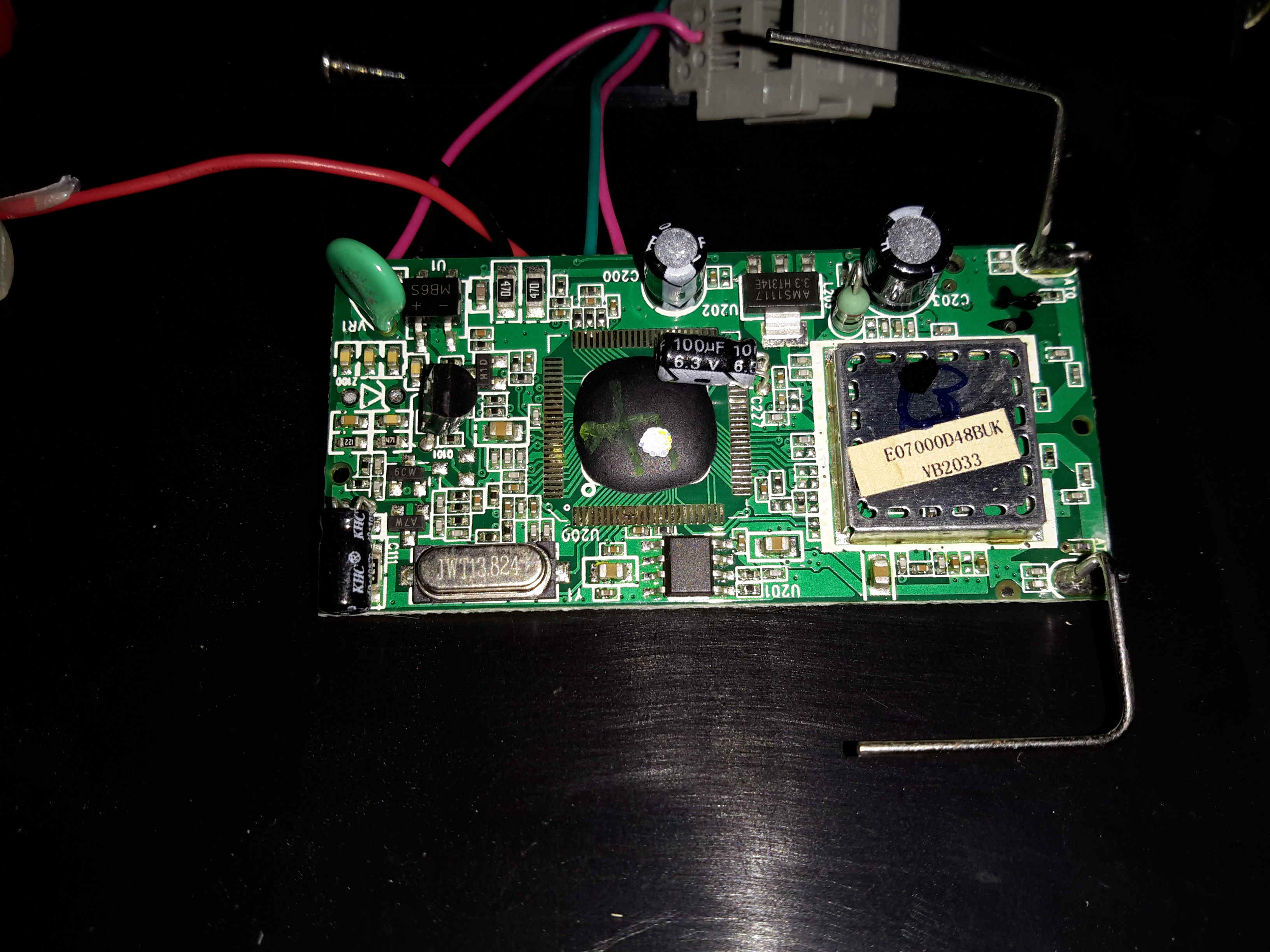
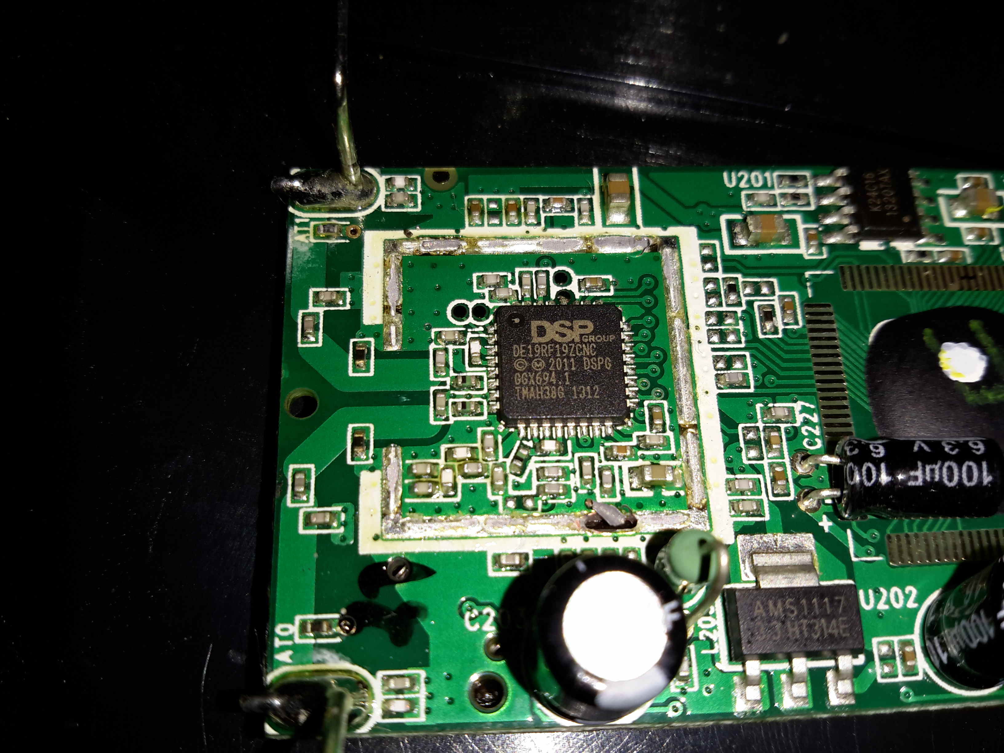
Base Unit PCB
Inside the base unit is a similar board, just without the keypad. Main microcontroller is again a COB device, the RF IC is under the shield.
Main Chipset
Removing the shield reveals the same IC as in the handset, only this PCB has a pair of antennas.
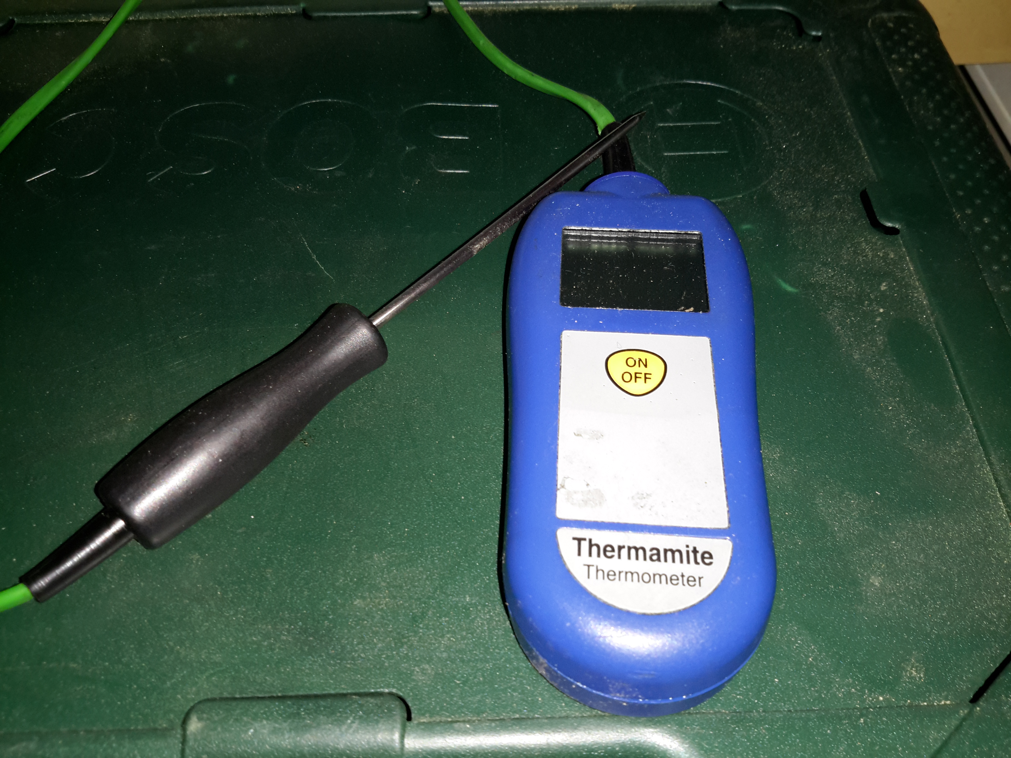
Here’s another bit of commercial gear, a catering thermometer. These are used to check the internal temperature of foods such as meat, to ensure they’re cooked through.
This was given to me with some damage, the battery cover is missing & the plastic casing itself is cracked.
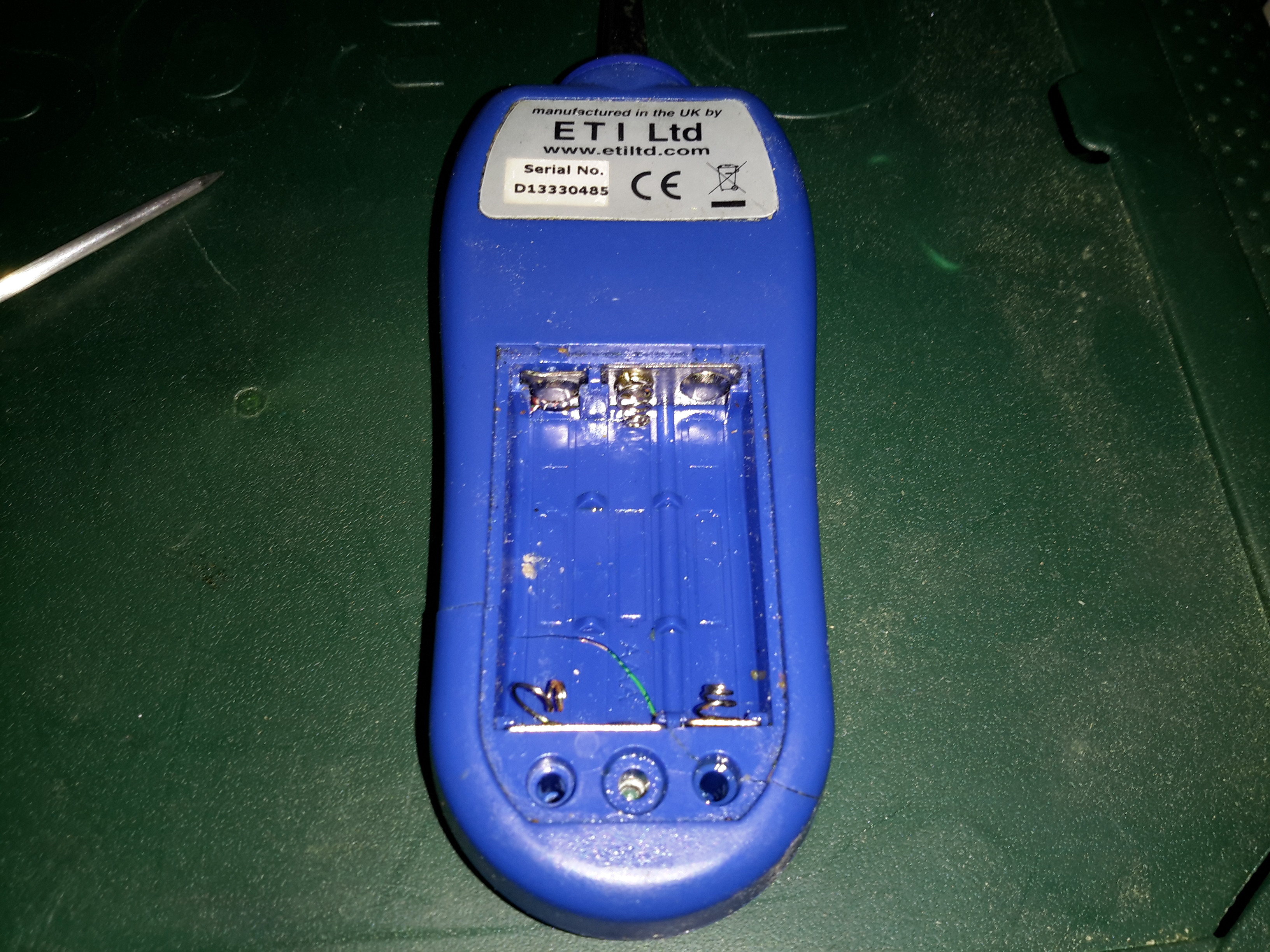
Battery Compartment
Power is provided by 3 AAA cells, for 4.5v
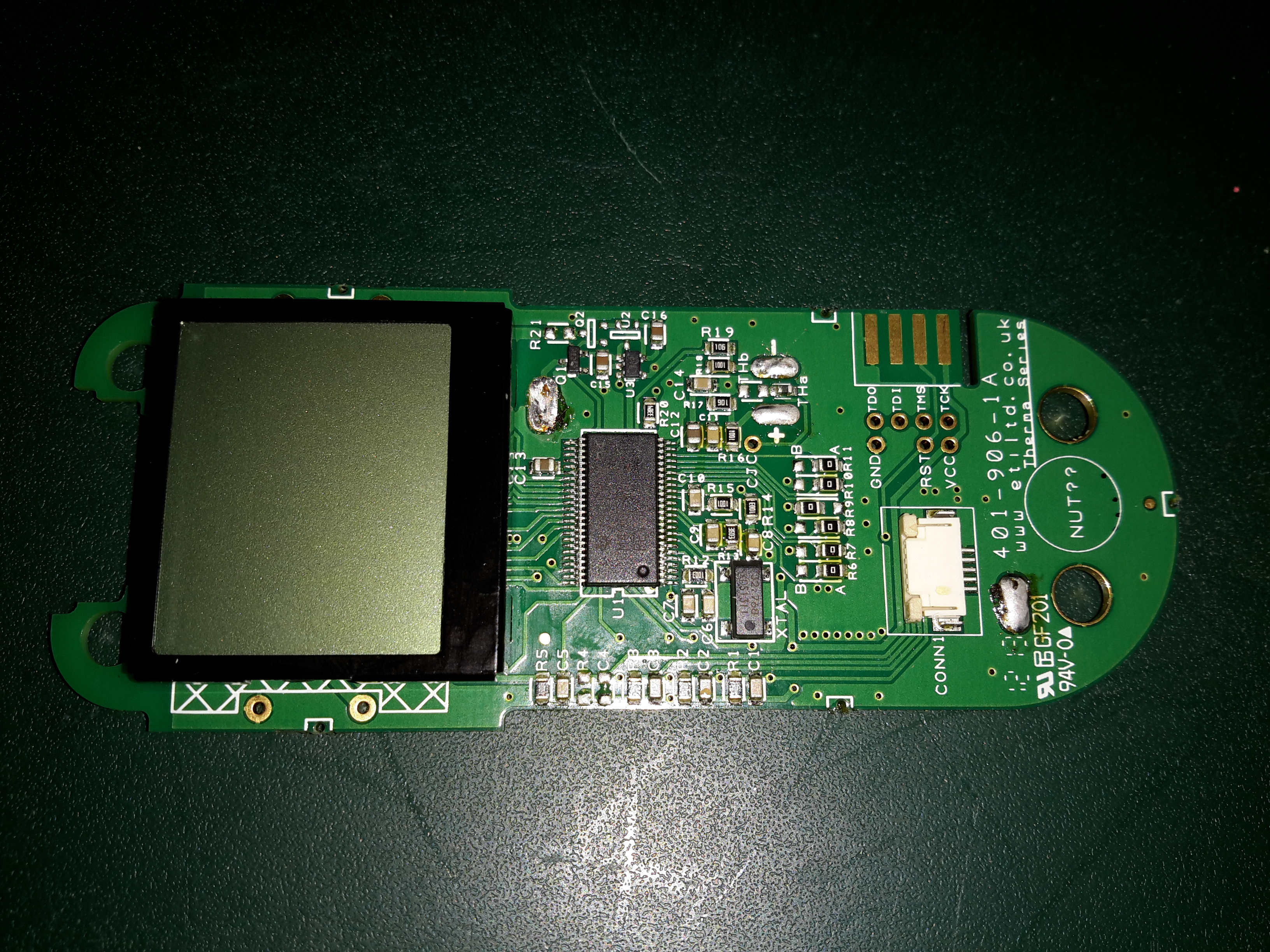
Main PCB
There’s not much to these units, the large LCD at the top is driven by the IC in the centre. A programming header is also present on the board near the edge.
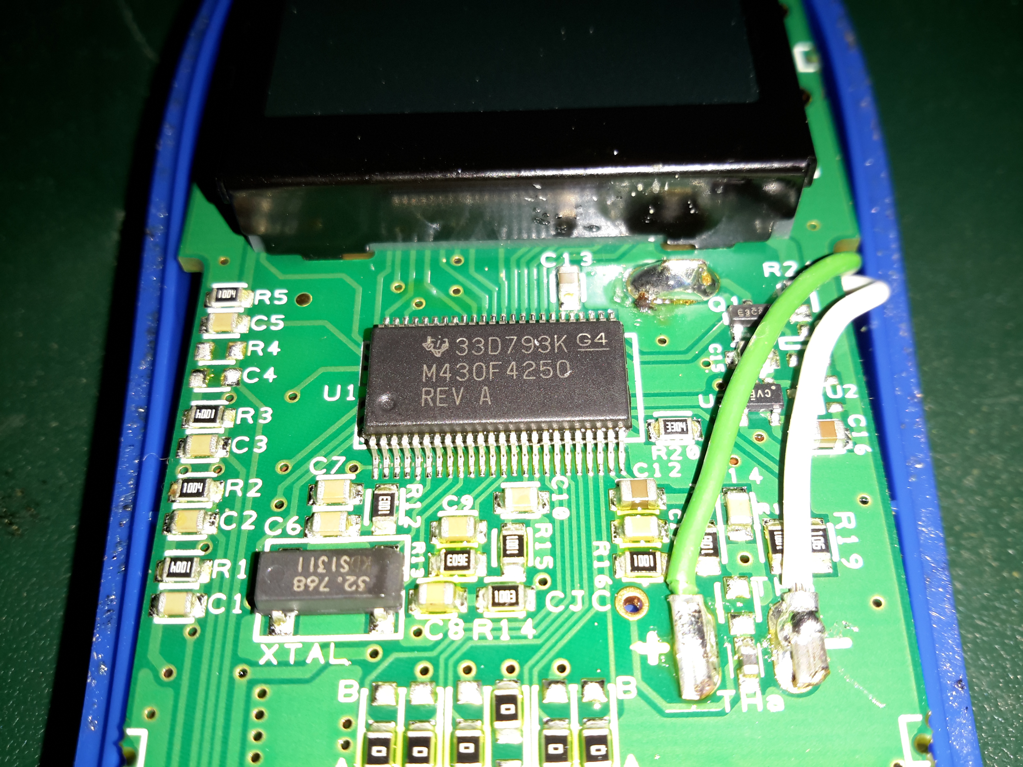
Microcontroller
The core logic is taken care of with a Texas Instruments M430F4250 MSP430 Mixed-Signal Microcontroller. This MCU has onboard 16-bit Sigma-Delta A/D converter, 16-bit D/A converter & LCD driver. Clock is provided by a 32.768kHz crystal.
The probe itself is just a simple thermistor bonded into a stainless steel rod.
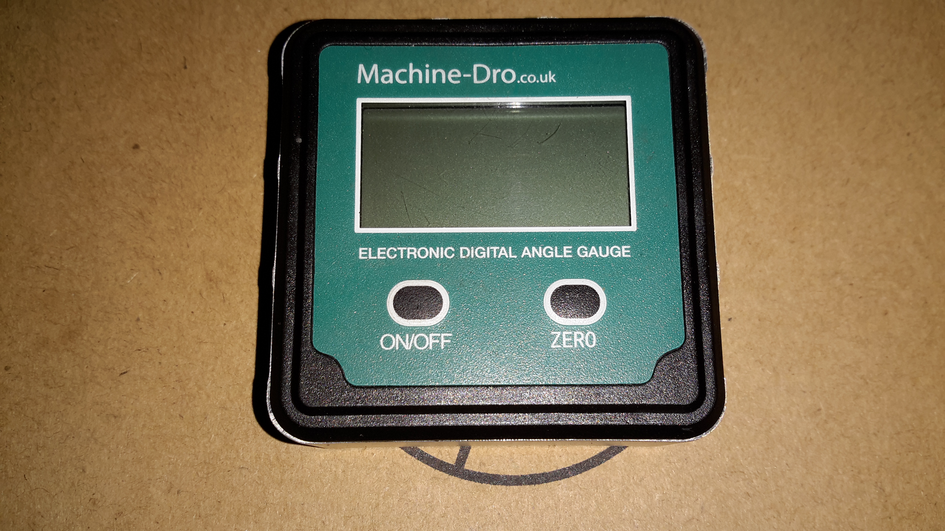
Here’s a useful tool for the kit, a digital angle gauge/protractor. These use a silicon sensor to show the number of degrees the unit is out of level.
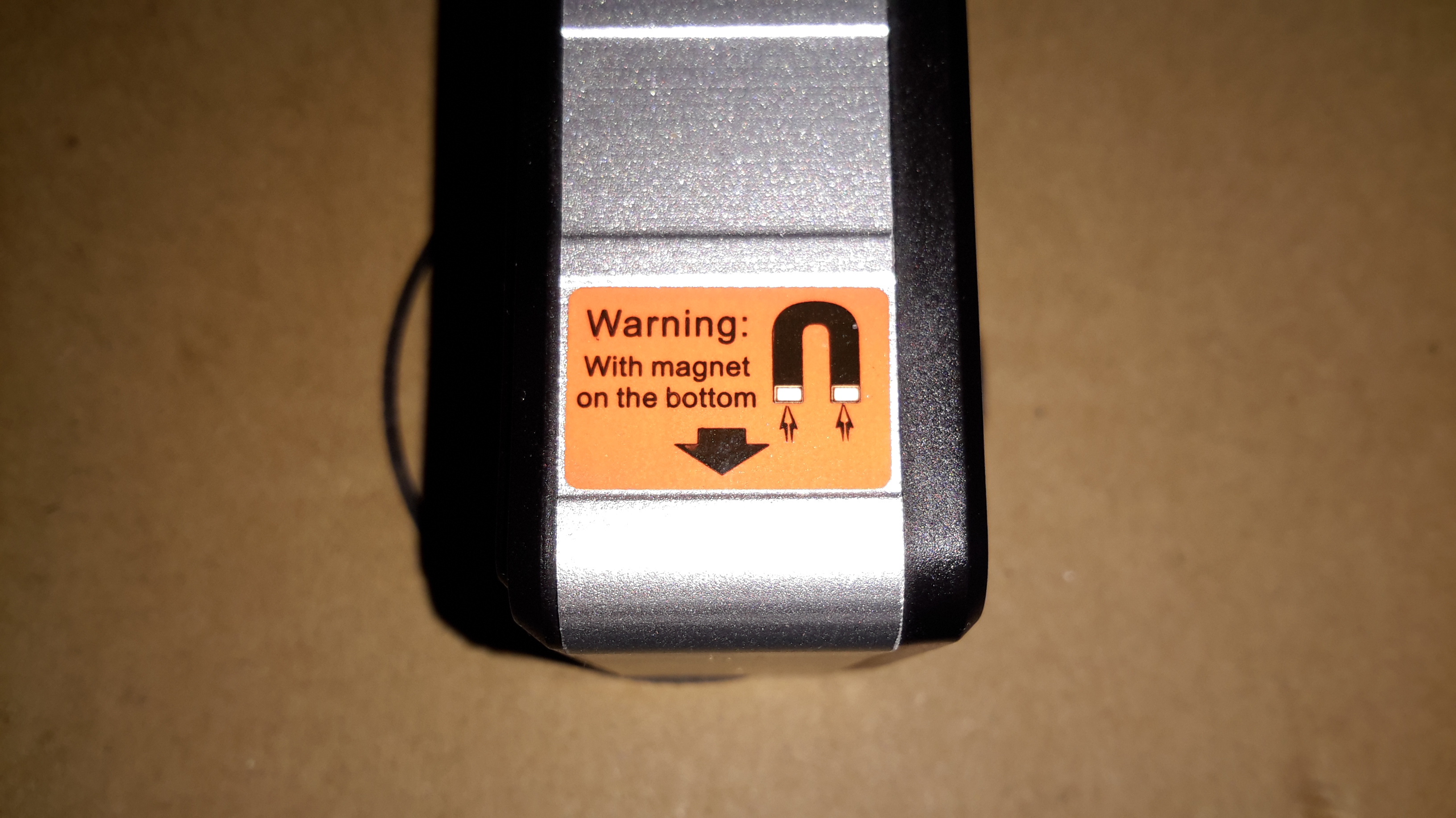
Magnets!
Magnets are provided in the base, so the tool can attach to any ferrous surface.
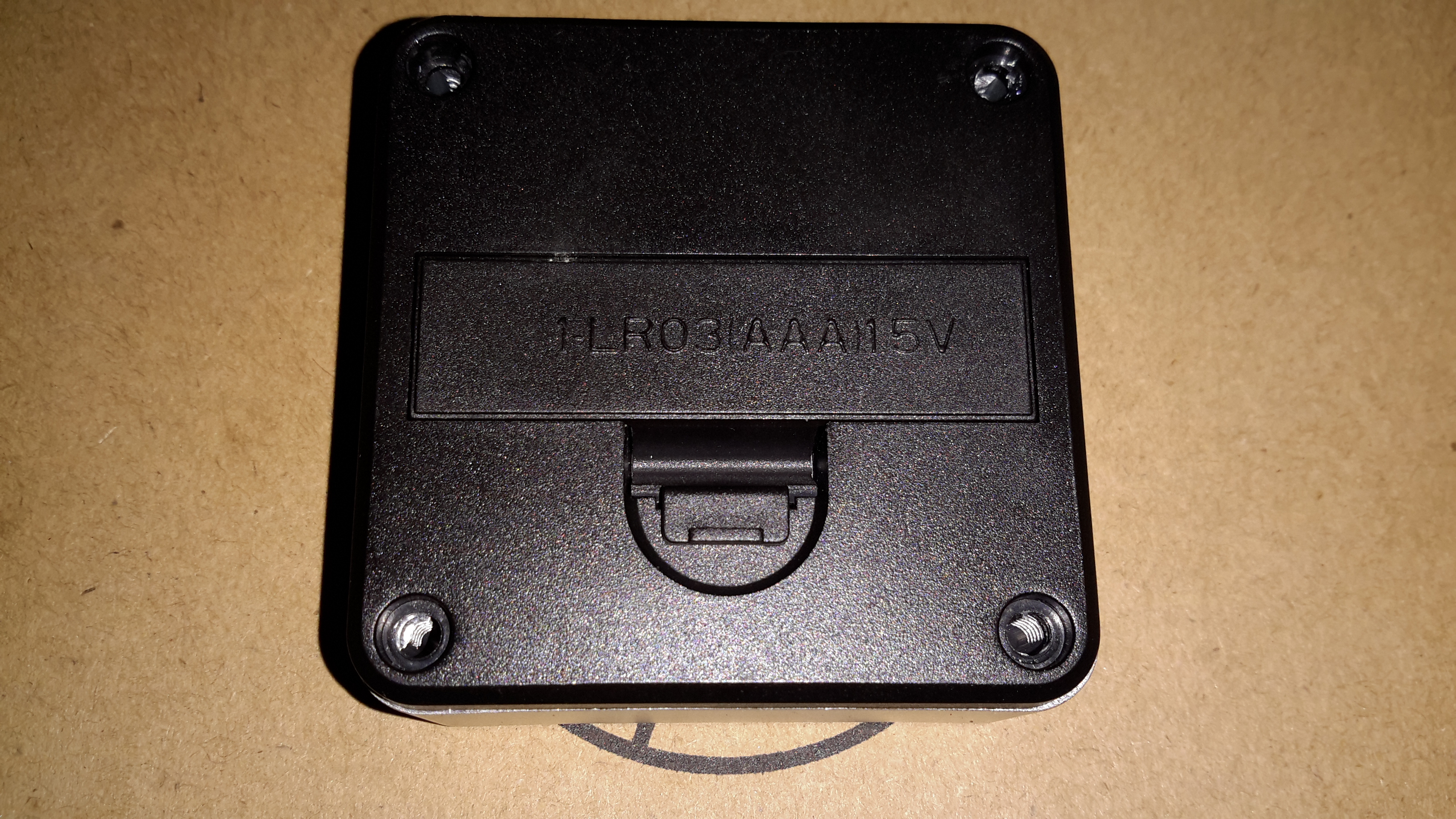
Battery Box
Power is provided by a single AAA cell.
Main PCB
Removing the rear cover reveals the brains of the unit, and there’s not much to it at all. The main microcontroller is a CoB-type device, so no part numbers available from that one.
Sensing Element
The IC to the left of the main microcontroller is the sensing element. There’s no markings on this inclinometer IC so I’m not sure of the specs, but it will be a 3D-MEMS device of some sort.
Power Supply
The other side of the PCB has the power supply for the logic, and a serial EEPROM, probably storing calibration data.
From the factory, the GY561 meter uses alkaline AAA cells for power. As these are not rechargable, and I don’t carry any other devices that take such batteries, I figured I’d replace them with a single Lithium Polymer cell that I can charge via USB.
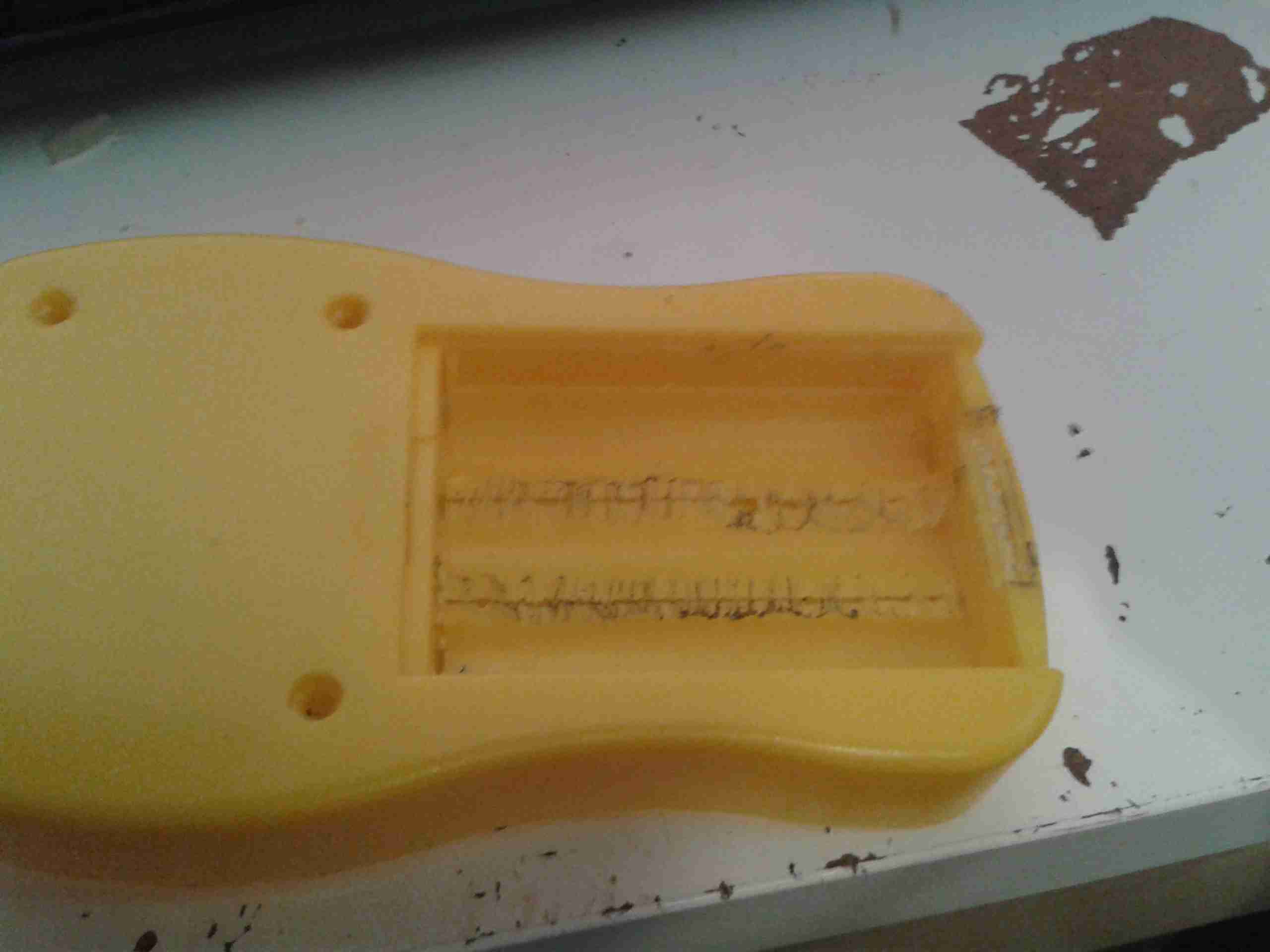
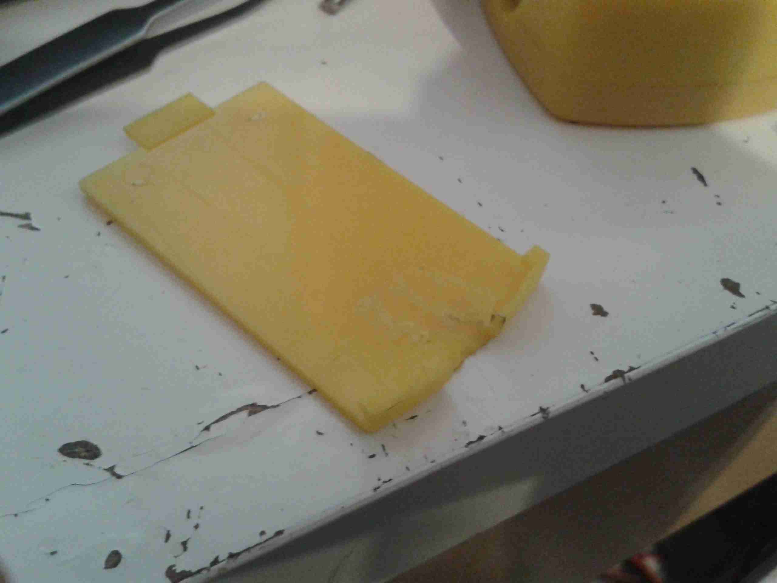
Battery Compartment
Here’s the battery compartment, with the original spring terminals removed.
I searched eBay for a suitable sized cell, and settled on a 1000mAh type, with dimensions of 47mm x 28mm x 7mm.
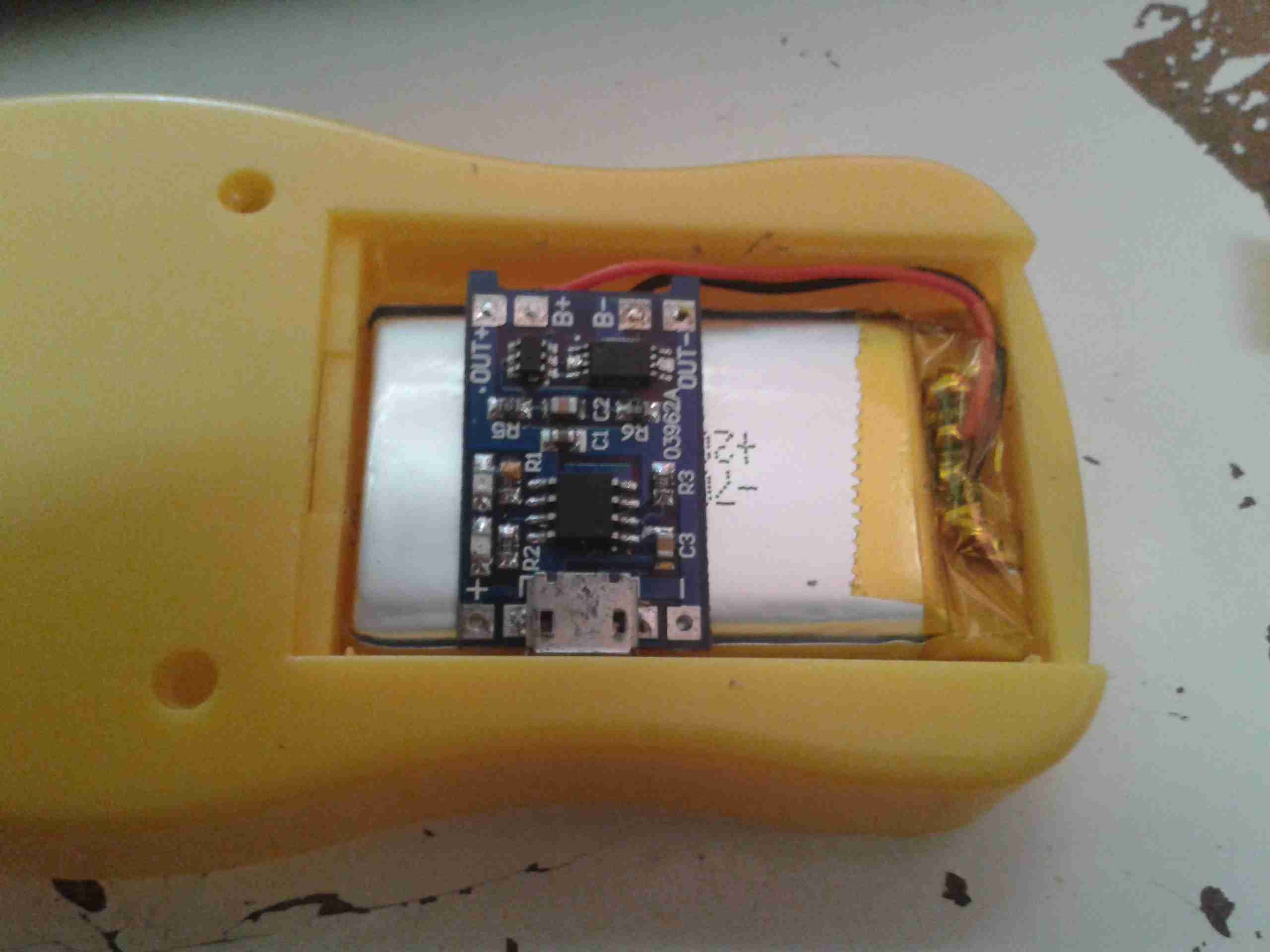
This size cell required a small amount of modification to the battery compartment to make it fit properly with the associated charge & protection circuitry.
Modified Compartment
Here’s the modifications made to the compartment, I’ve ground away the plastic to make the bottom flat, and the plastic tabs that retained the original spring terminals.
Modifications
After grinding away the original battery spring holders with a dremel, the cell fits perfectly in the available space. The small PCB on the top of the cell is the USB charger & protection.
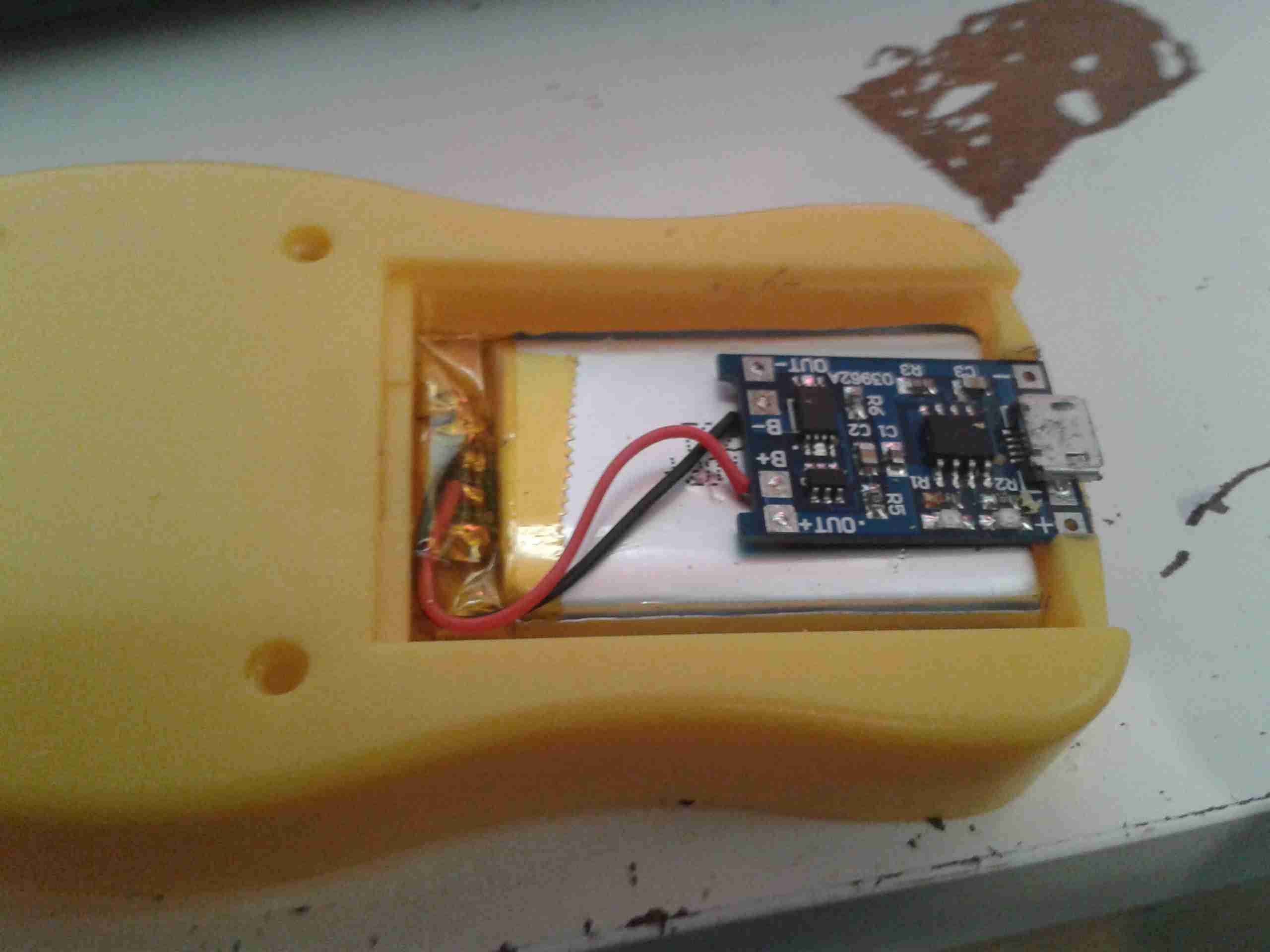
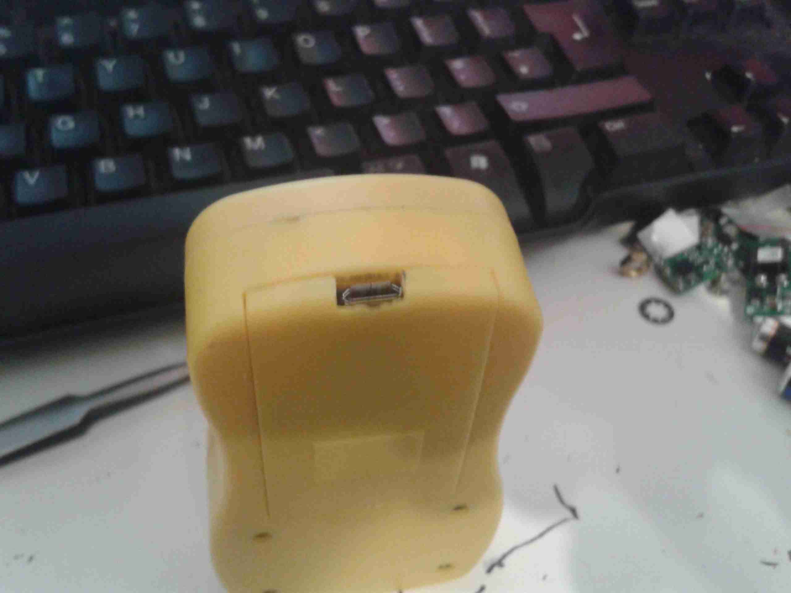
Charger
The charger is located in a slot cut in the bottom of the casing, so the USB port is accessible from outside the compartment.
Wiring
Here’s the rest of the wiring completed, with the power wires going through holes in the bottom of the battery compartment to join onto the PCB where the original terminals were located. I have insulated the solder joints on the control PCB with some Kapton tape to prevent any shorts against the lithium cell.
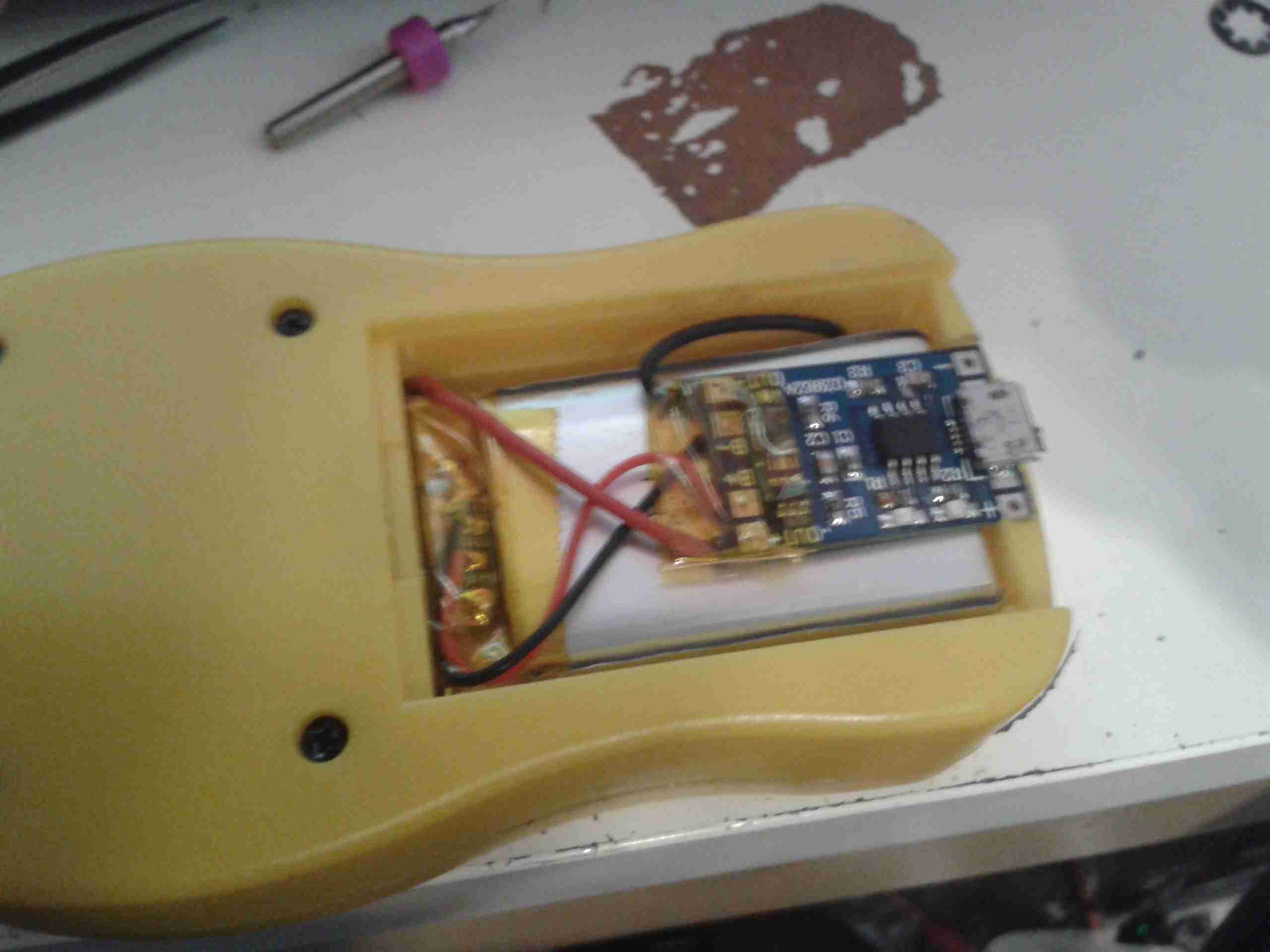
Battery Cover
A small cutout was also required in the battery cover to allow the USB connector to poke out. This was easy to do on the soft plastic with a Dremel tool.
Charging Port
With the battery cover installed, the USB port is nicely recessed into the edge.
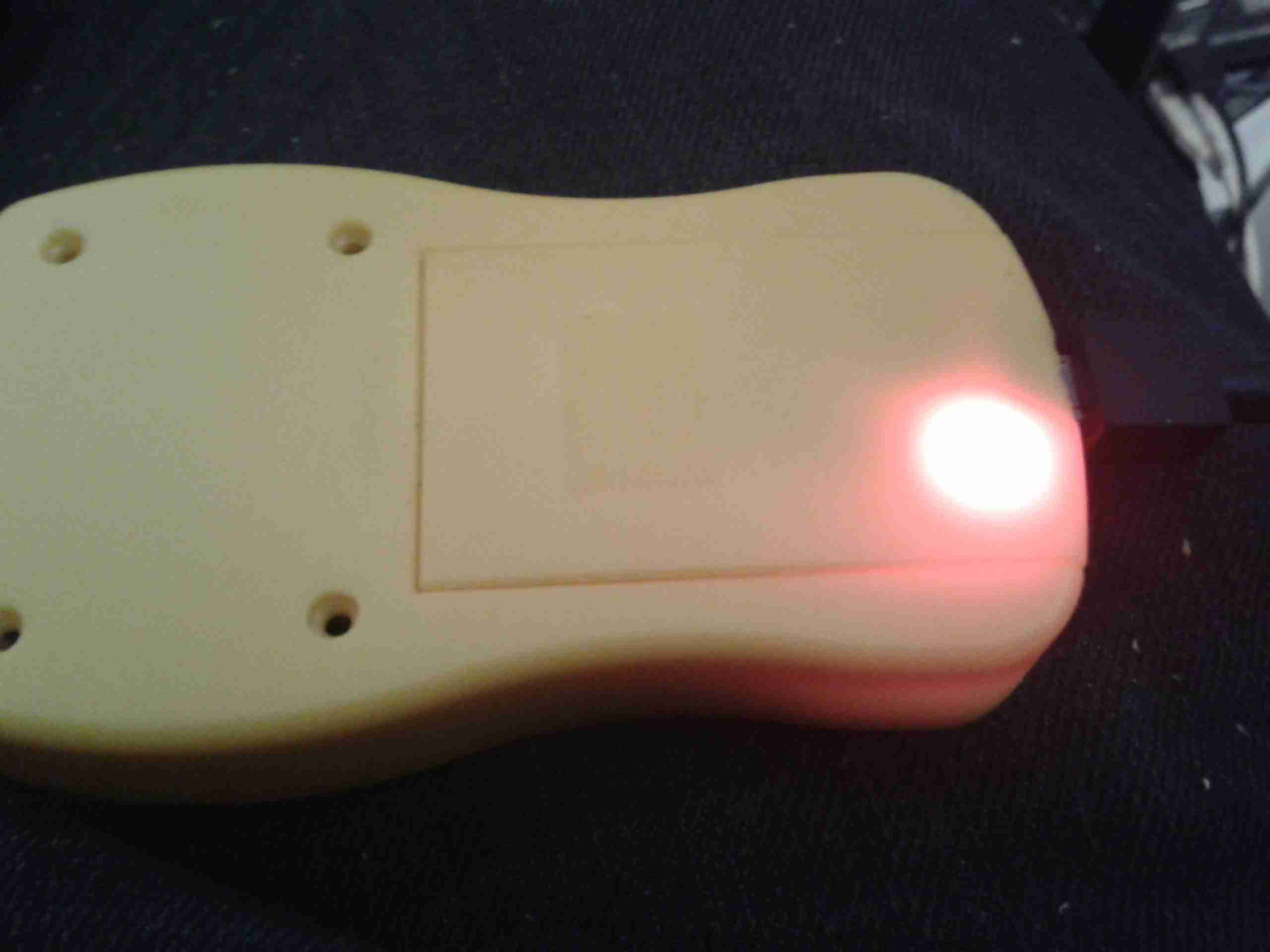
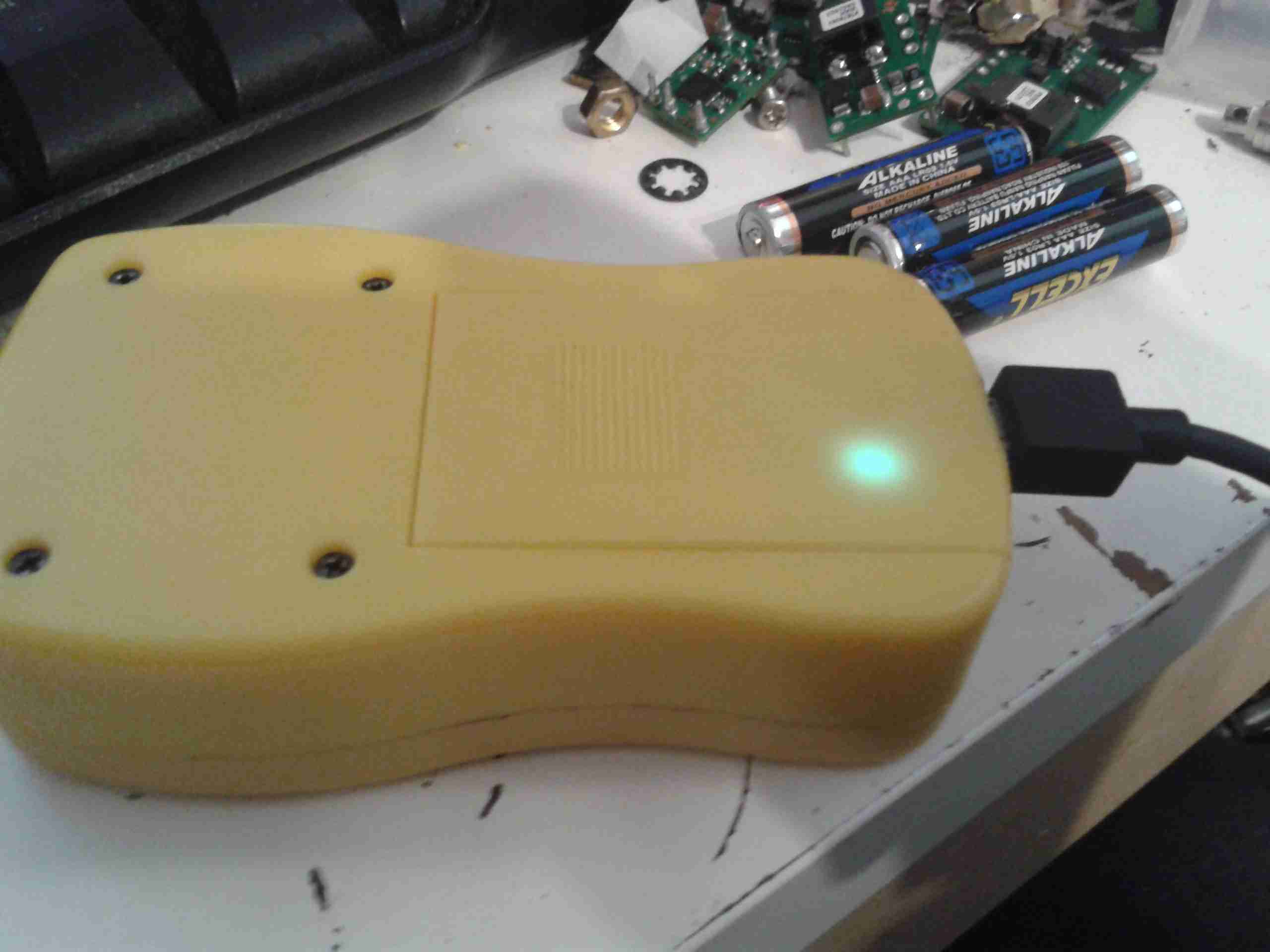
Charging LED
The indicator LEDs on the charging & control board show nicely through the plastic, here’s the unit on charge. When the charge is complete, another LED lights as shown below.
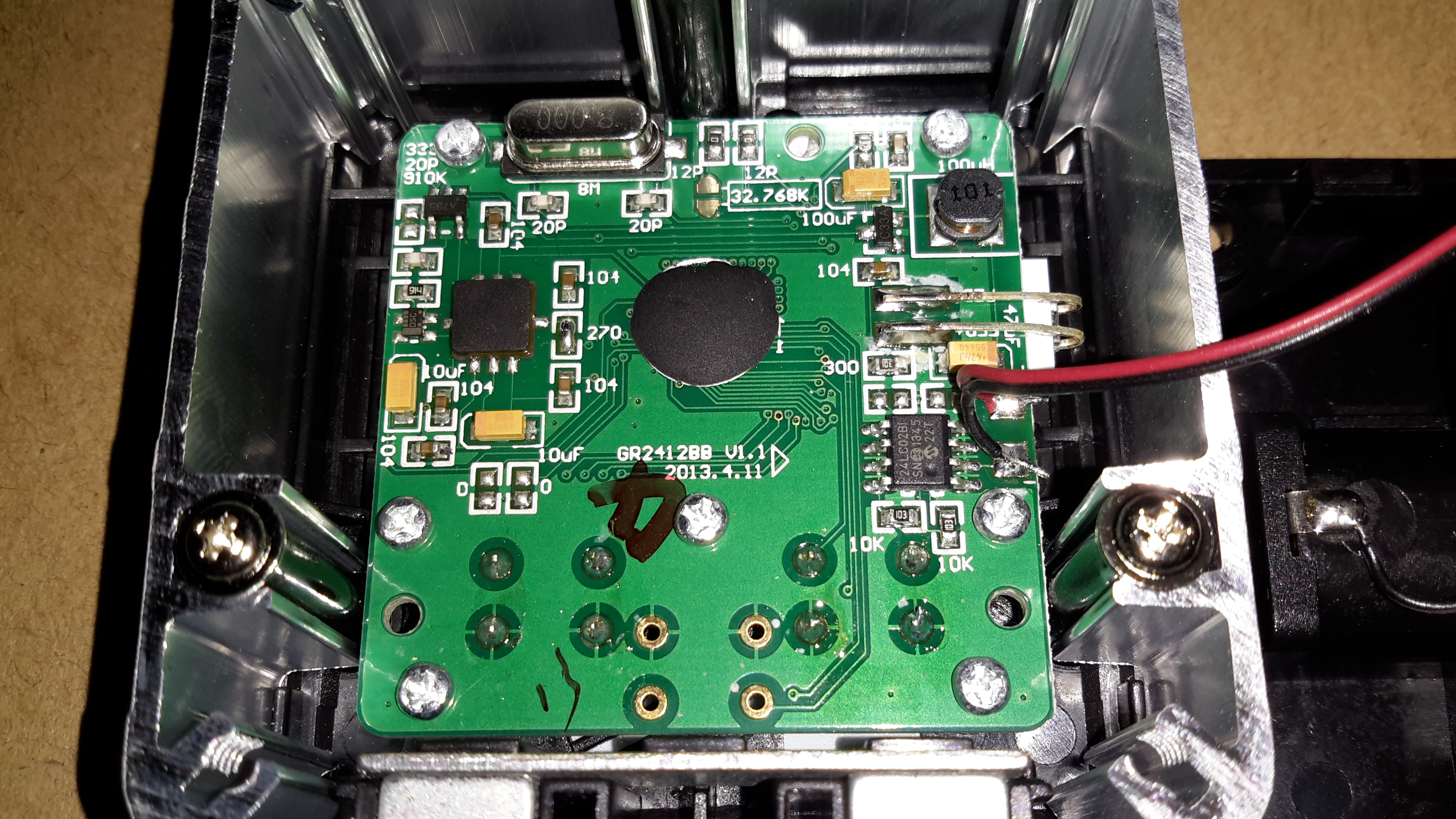
The latest addition to my radio shack is the GY561 frequency & power meter, which has already come in useful for measuring the output power of all my radios.
GY561
It’s a small device, roughly the same size & weight as a stock UV-5R. Power is provided by 3 AAA cells.
Display
The display is a standard HD44780 8×2 module. The display on this unit isn’t backlit, so no operating in the dark.
Cover Removed
The cover pops off easily to allow access to the internals, without having to remove any screws!
The 4 screws on the back of the unit hold the heatsink plate for the 50W 50Ω dummy load resistor.
Removing the cover reveals a couple of adjustments, for frequency & RF power calibration.
There are also 3 tactile switches that aren’t on the front panel. According to the manual (which in itself is a masterpiece of Chinglish), they are used to software calibrate the unit if an accurate RF power source is available. I will attempt to do a reasonable translation when time allows.
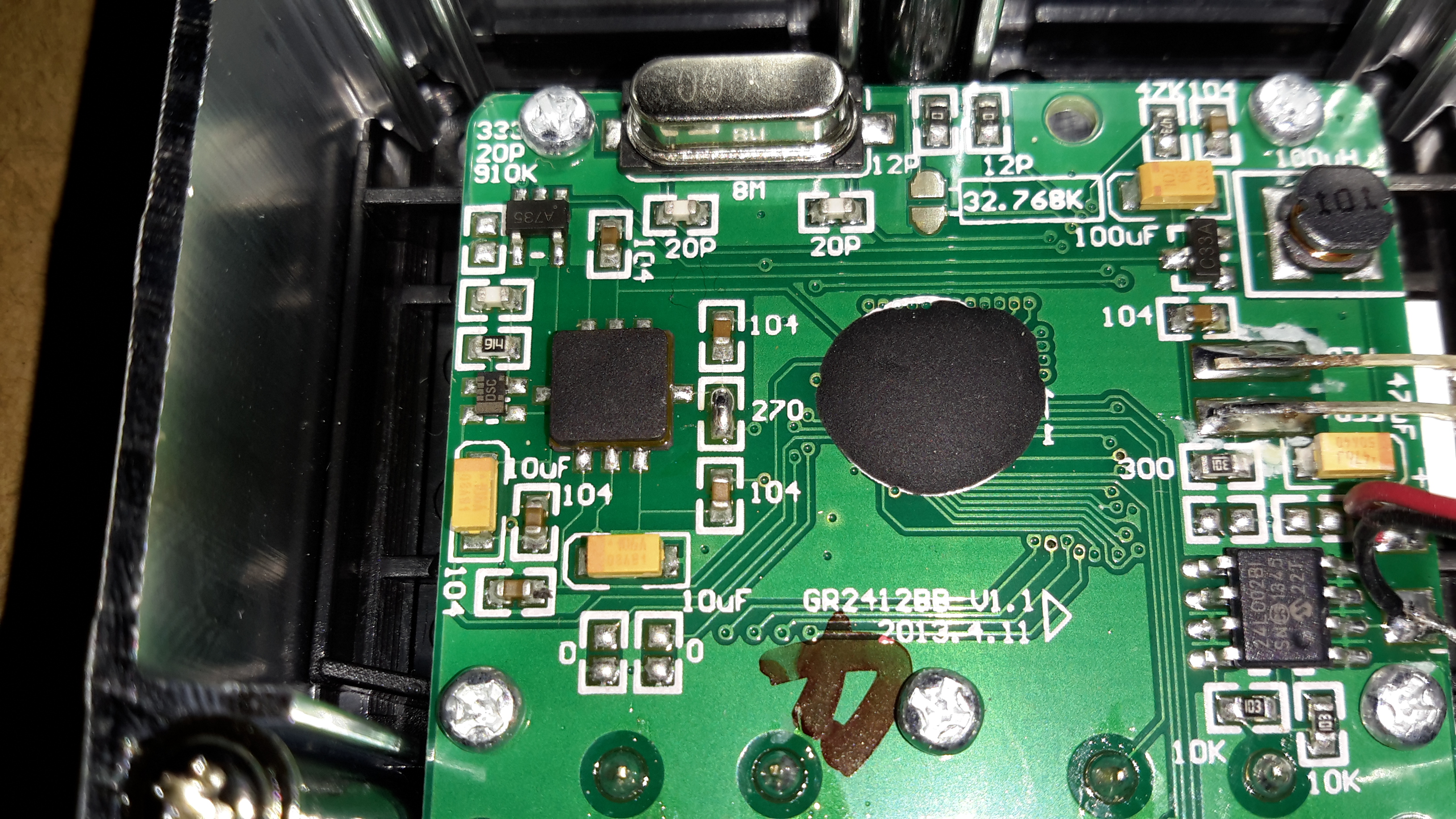
Disassembly further than this involves some desoldering in awkward places, so a search of the internet revealed an image of the rest of the internal components. In the case of my meter, all the part numbers have been scrubbed off the ICs in an attempt to hide their purpose. While it’s possible to cross-reference IC databooks & find the part numbers manually, this process is a time consuming one. Luckily the image I managed to locate doesn’t have the numbers scrubbed.
Total Disassembly
Under the LCD is some 74HC series logic, and a prescaler IC as seen in the previous frequency counter post. However in this unit the prescaler is a MB506 microwave band version to handle the higher frequencies specified.
In this case however the main microcontroller is an ATMEGA8L.
This is complemented by a SN54HC393 4-bit binary counter for the frequency side of things. This seems to make it much more usable down to lower frequencies, although the manual is very generous in this regard, stating that it’s capable of reading down to 1kHz. In practice I’ve found the lowest it reliably reads the frequency input is 10MHz, using my AD9850 DDS VFO Module as a signal source.
It did however read slightly high on all readings with the DDS, but this could have been due to the low power output of the frequency source.
Just like the other frequency counter module, this also uses a trimmer capacitor to adjust the microcontroller’s clock frequency to adjust the calibration.
The power supply circuitry is in the bottom left corner of the board, in this case a small switching supply. The switching regulator is needed to boost the +4.5v of the batteries to +5v for the logic.
Also, as the batteries discharge & their terminal voltage drops, the switching regulator will allow the circuit to carry on functioning. At present I am unsure of the lower battery voltage limit on the meter, but AAA cells are usually considered dead at 0.8v terminal voltage. (2.4v total for the 3 cells).
When turned on this meter draws 52mA from the battery, and assuming 1200mAh capacity for a decent brand-name AAA cell, this should give a battery life of 23 hours continuous use.
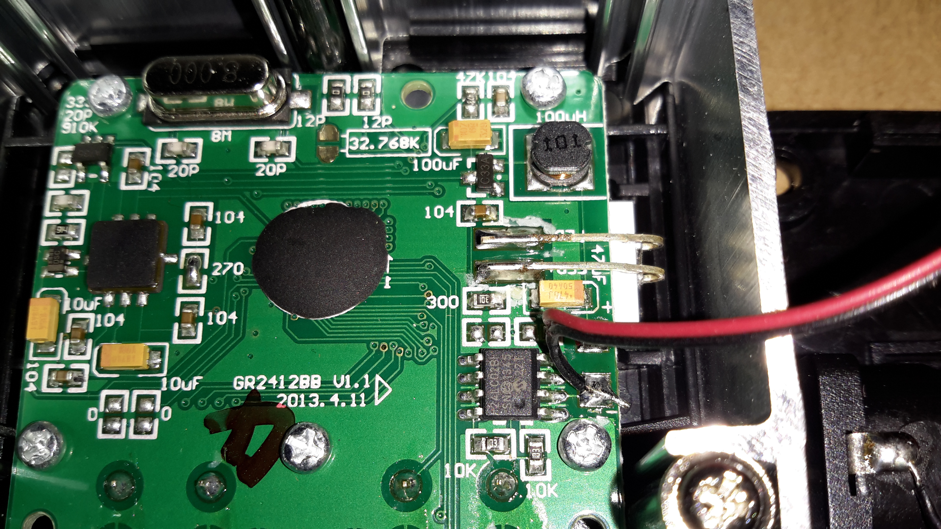
On the back of the main PCB is a 5v relay, which seems to be switching an input attenuator for higher power levels, although I only managed to trigger it on the 2m band.
Finally, right at the back attached to an aluminium plate, is the 50Ω dummy load resistor. This component will make up most of the cost of building these, at roughly £15.
On my DVM, this termination reads at about 46Ω, because of the other components on the board are skewing the reading. There are a pair of SMT resistors, at 200Ω & 390Ω in series, and these are connected across the 50Ω RF resistor, giving a total resistance of 46.094Ω.
This isn’t ideal, and the impedance mismatch will probably affect the calibration of the unit somewhat.
The heatsinking provided by the aluminium plate is minimal, and the unit gets noticeably warm within a couple of minutes measuring higher power levels.
High power readings should definitely be limited to very short periods, to prevent overheating.
The RF is sampled from the dummy load with a short piece of Teflon coax.
There’s a rubber duck antenna included, but this is pretty useless unless it’s almost in contact with the transmitting antenna, as there’s no input amplification. It might be handy for detecting RF emissions from power supplies, etc.
For the total cost involved I’m not expecting miracles as far as accuracy is concerned, (the manual states +/-10% on power readings).
The frequency readout does seem to be pretty much spot on though, and the ability to calibrate against a known source is handy if I need some more accuracy in the future.
I’ve also done an SWR test on the dummy load, and the results aren’t good.
At 145.500 MHz, the SWR is 3:1, while at 433.500 it’s closer to 4:1. This is probably due to the lower than 50Ω I measured at the meter’s connector.
These SWR readings also wander around somewhat as the load resistor warms up under power.
I’ll probably also replace the AAA cells with a LiPo cell & associated charge/protection circuitry, to make the unit chargeable via USB. Avoiding disposable batteries is the goal.
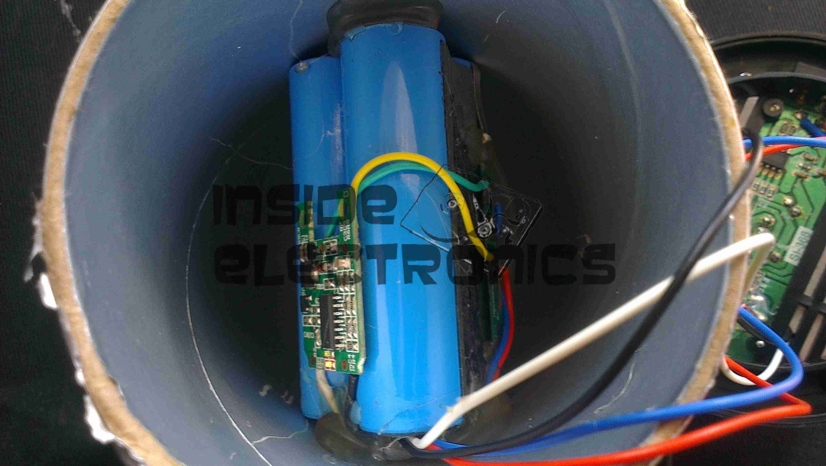
These speakers are available free from Pringles, with two packs bought. Normally running on 3x AAA cells, I have made modifications to include a high capacity Li-Ion battery & USB charging.
18650 Battery
New battery is 3x 18650 Li-Ion cells in parallel, providing ~6600mAh of capacity. These are hot glued inside the top of the tube under the speaker, with the charging & cell protection logic.
The battery charging logic is salvaged from an old USB eCig charger, these are single cell lithium chargers in a small form factor ideal for other uses. Charging current is ~450mA.
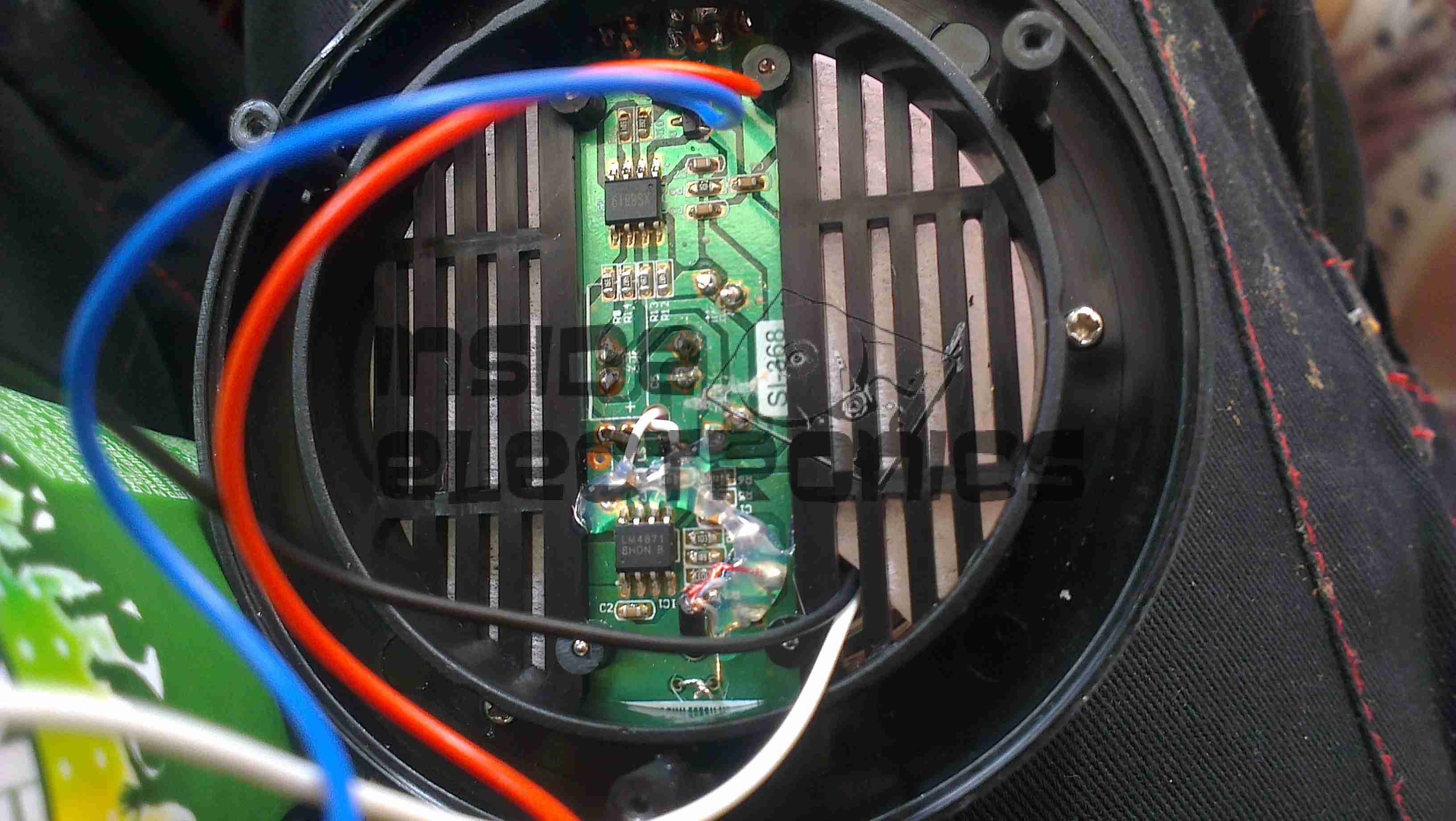
Amplifier Board
The cells are connected to the same points as the original AAA cells, with the other pair of wires going into the top of the device to connect to the MicroUSB charging port.
The amplifier in this is a LM4871 3W Mono amplifier IC, connected to a 6Ω 1W speaker.
The other IC on the board is unidentifiable, but provides the flashing LED function to the beat of the music.
Here is a label maker, bought on offer at Maplin Electronics. Full Qwerty keyboard with 1 line dot matrix LCD display visible here. Power is 4 AAA cells or a 6v DC Adaptor.
Rear
Rear cover removed. Battery compartment is on the left hand side, space for the tape cartridge on the right. Ribbon cable leading to the thermal print head is on the far right, with rubber tape drive roller.
PCB
PCB under the top cover with the main CPU, a MN101C77CBM from Panasonic. This CPU features 48K Mask ROM & 3K of RAM. Max clock frequency is 20MHz. 32kHz clock crystal visible underneath a Rohm BA6220 Electronic speed controller IC.
This is used to drive the printer motor at a constant accurate speed, to feed the tape past the thermal head. Miniature potentiometer adjusts speed.
Ribbon cable at the bottom of the board connects to the print head, various wiring at the left connects to the battery & DC Jack.
Printer Drive
Printer drive mechanism. Small DC motor drives the pinch roller though a gear train. DC Jack & reverse polarity protection diode is on the right.
This unit uses a centre negative DC jack, which is unusual.
Cartridge
Thermal tape cartridge, black text on white background.
Tip Jar
If you’ve found my content useful, please consider leaving a donation by clicking the Tip Jar below!
All collected funds go towards new content & the costs of keeping the server online.