Posted on Leave a comment

UM25C USB Power Meter

UM25C USB Power Meter

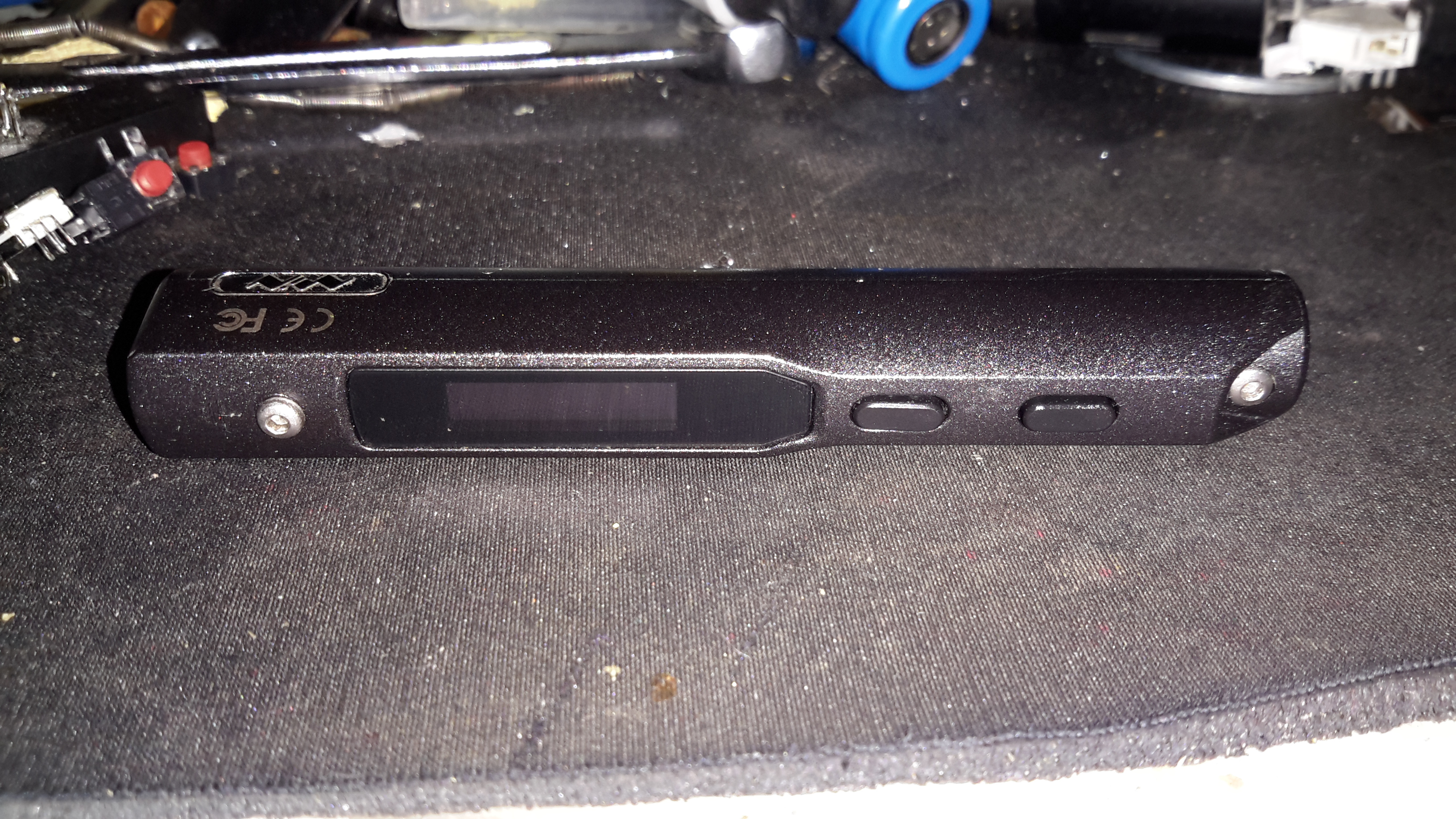
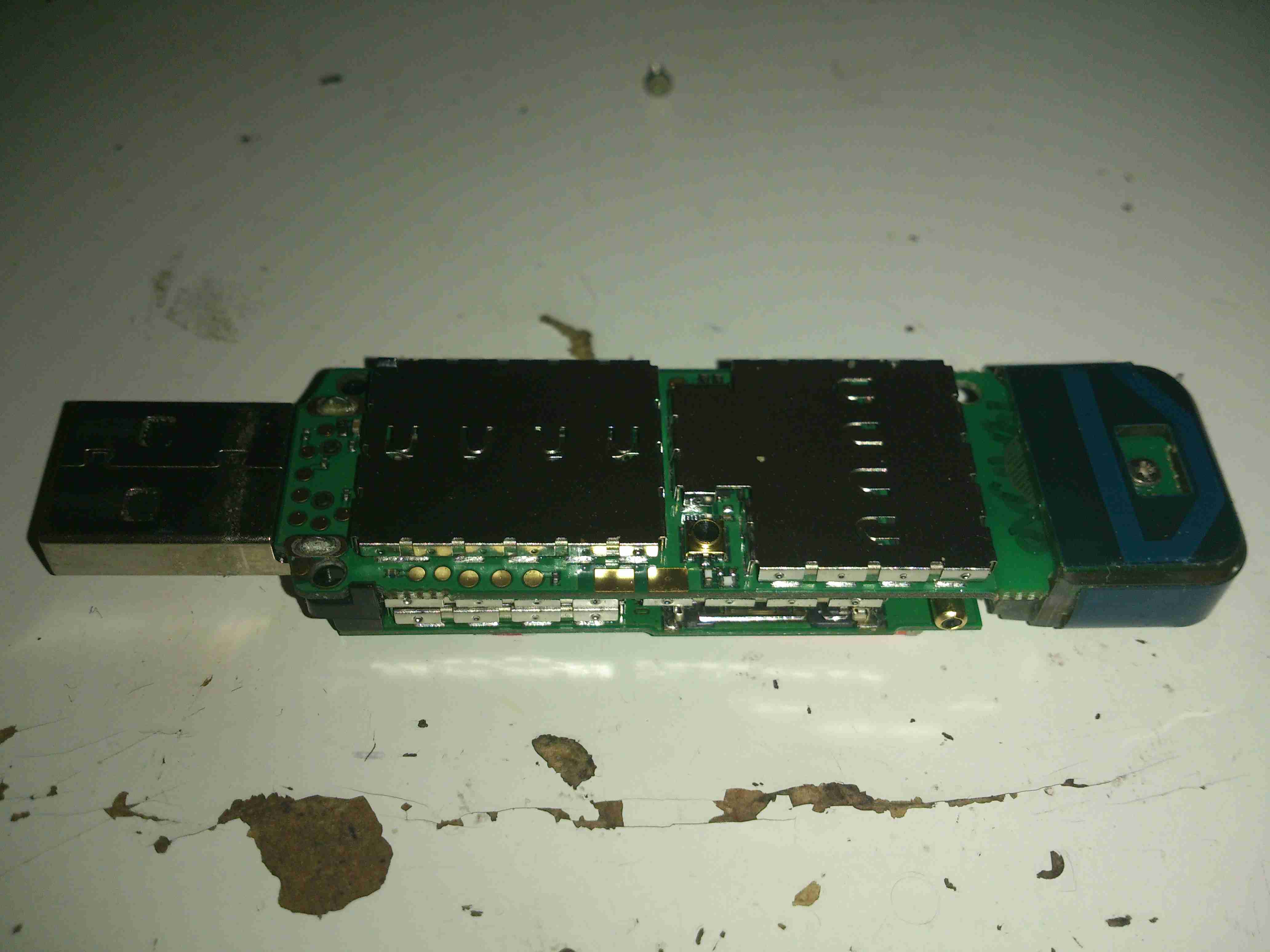
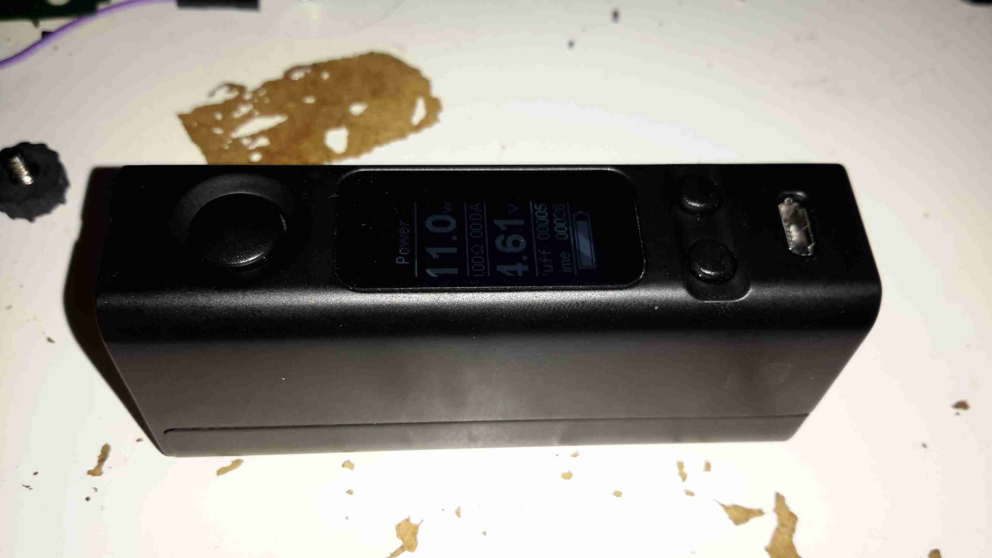
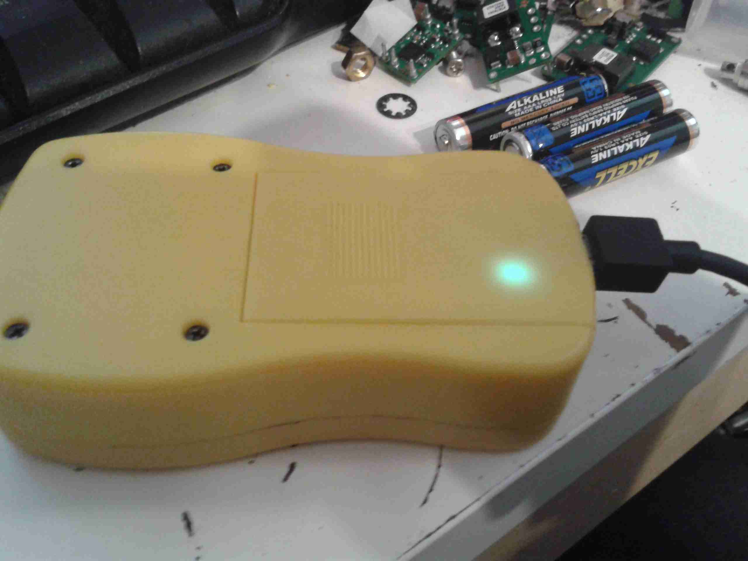
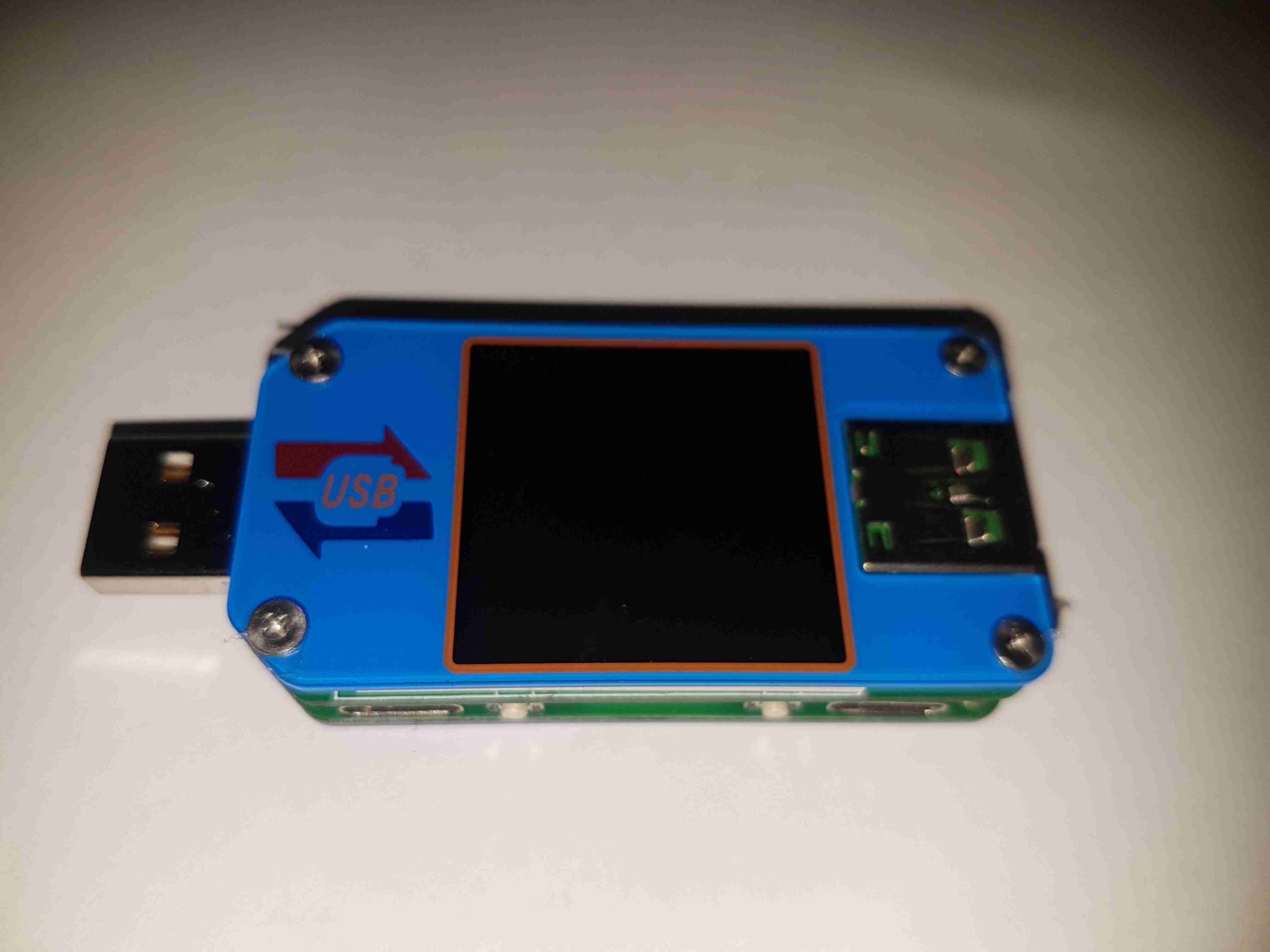
Here’s a nice little feature-packed USB power meter, the UM25C. This unit has USB-C along with the usual USB type A connectors, along with a bluetooth radio for remote monitoring of stats via a Windows or Android app. Construction is nice, it’s a stack of two PCBs, and polycarbonate cover plates, secured together with brass posts & screws.

Back Cover
Back Cover

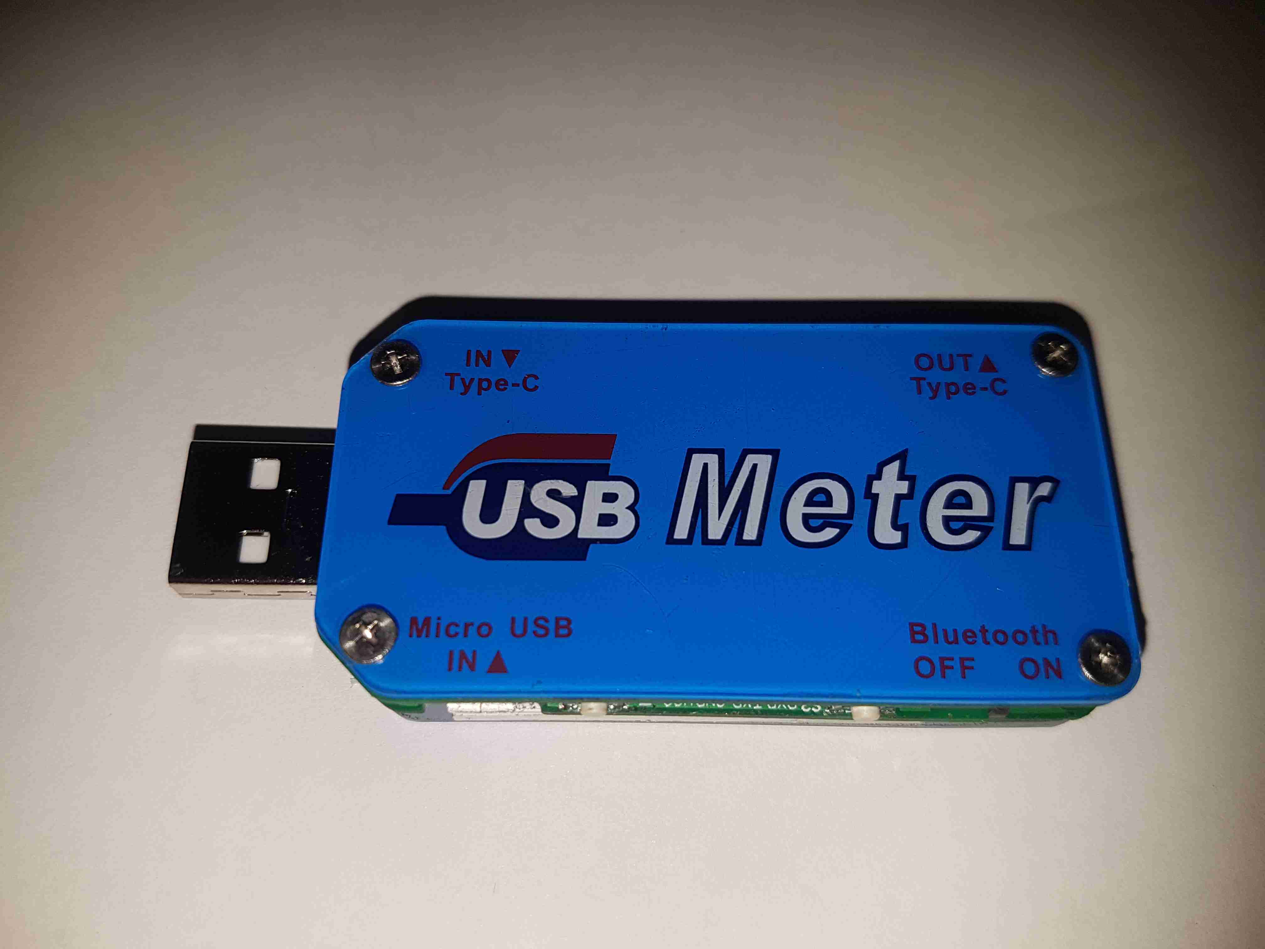
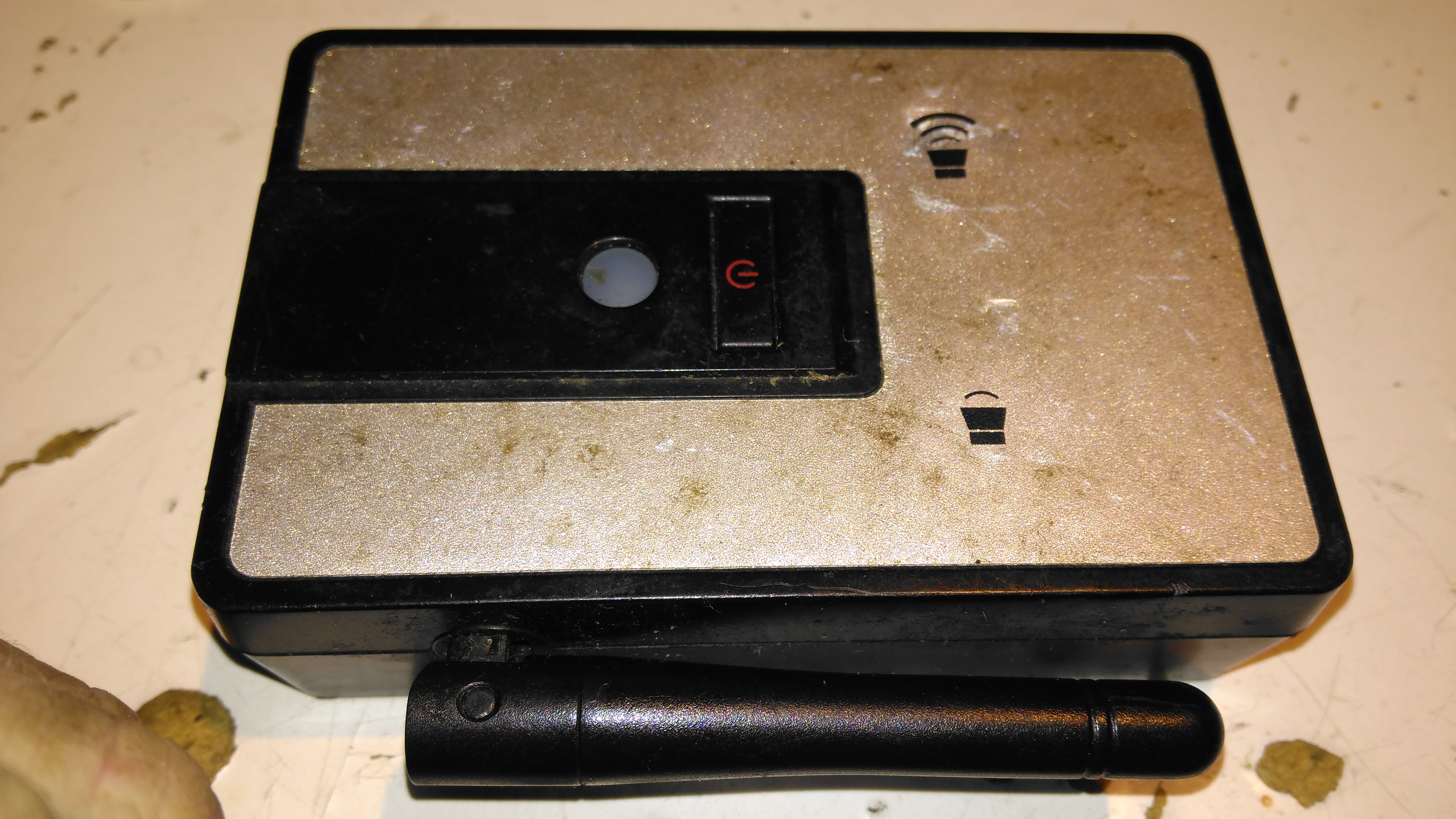
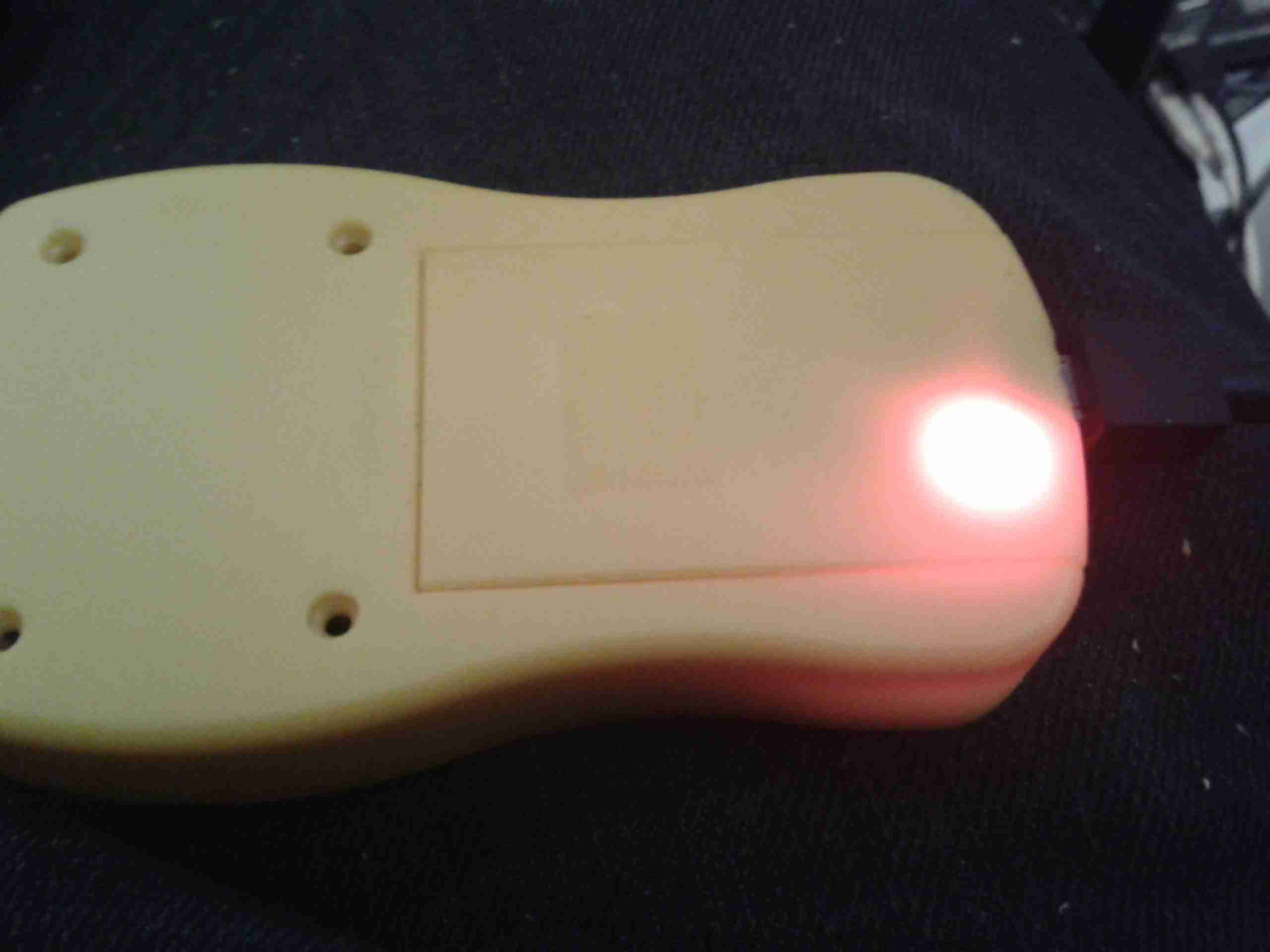
The back cover has the legend for all the side connectors, along with the logo.

USB Micro Input
USB Micro Input

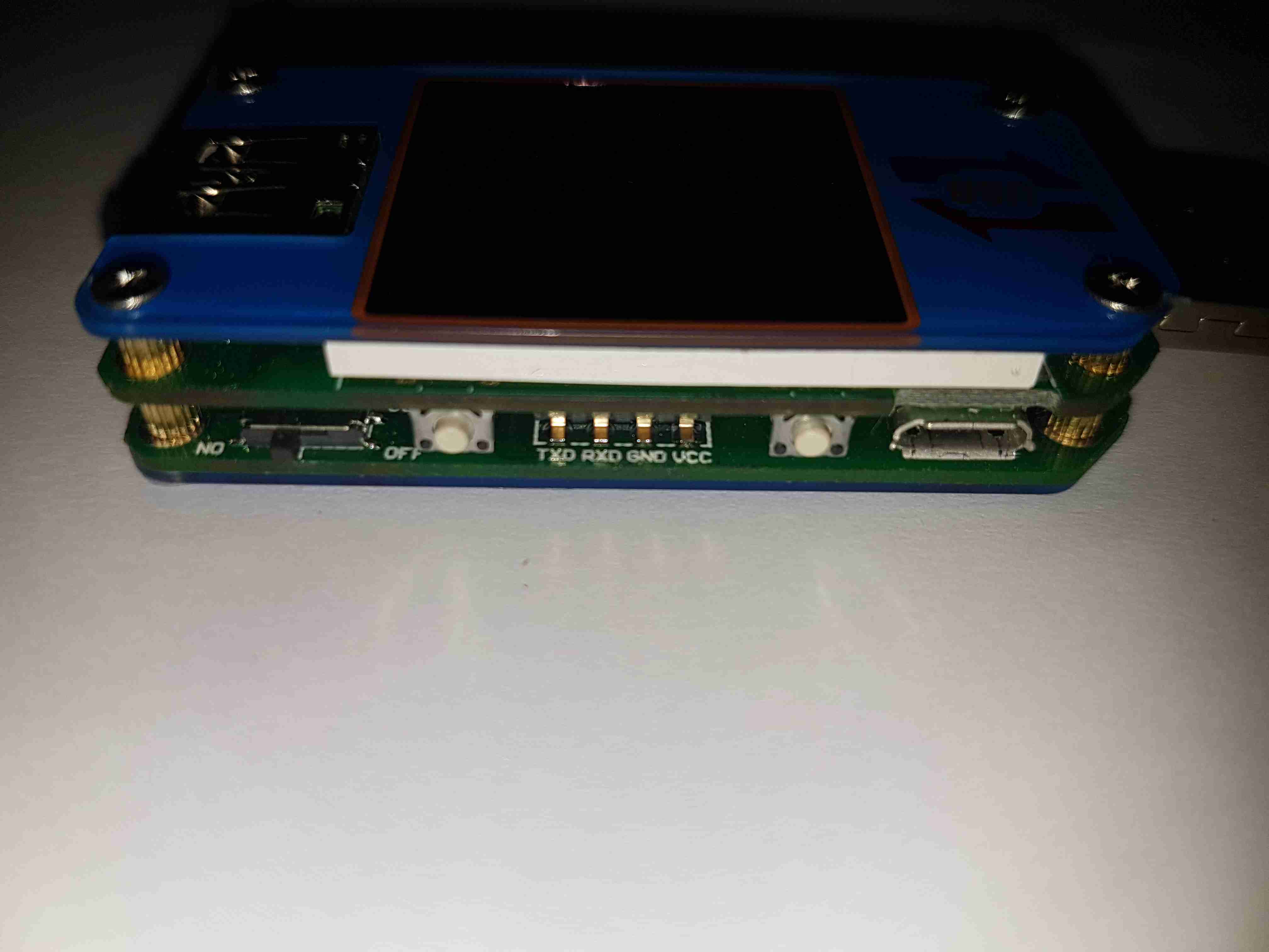
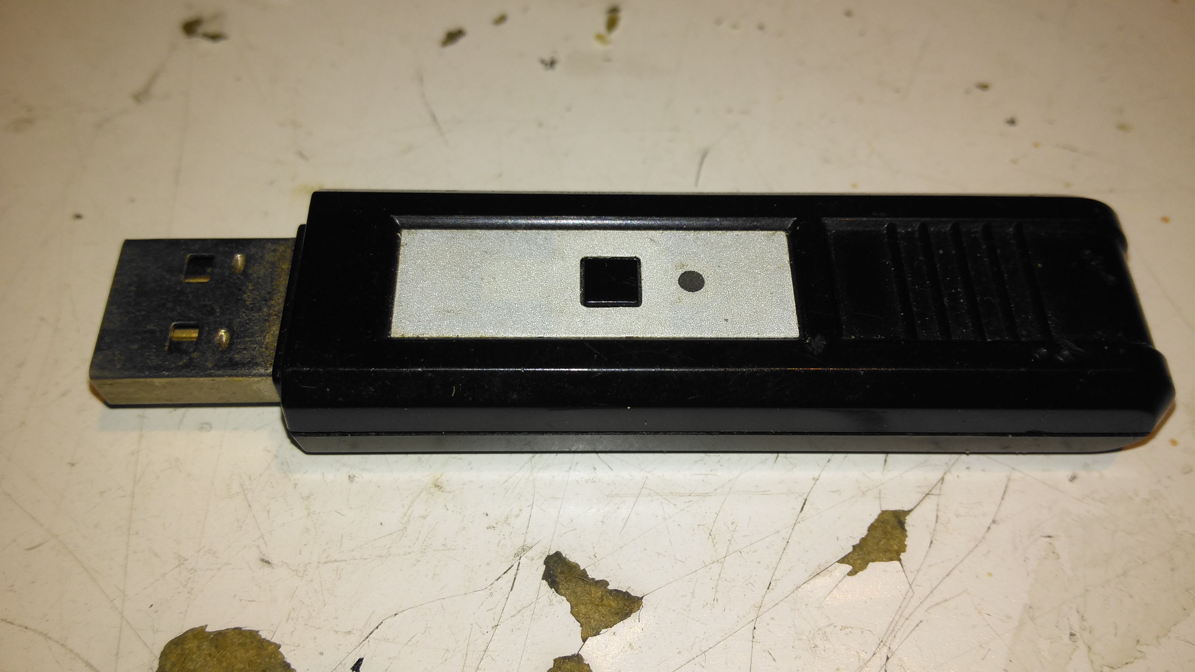
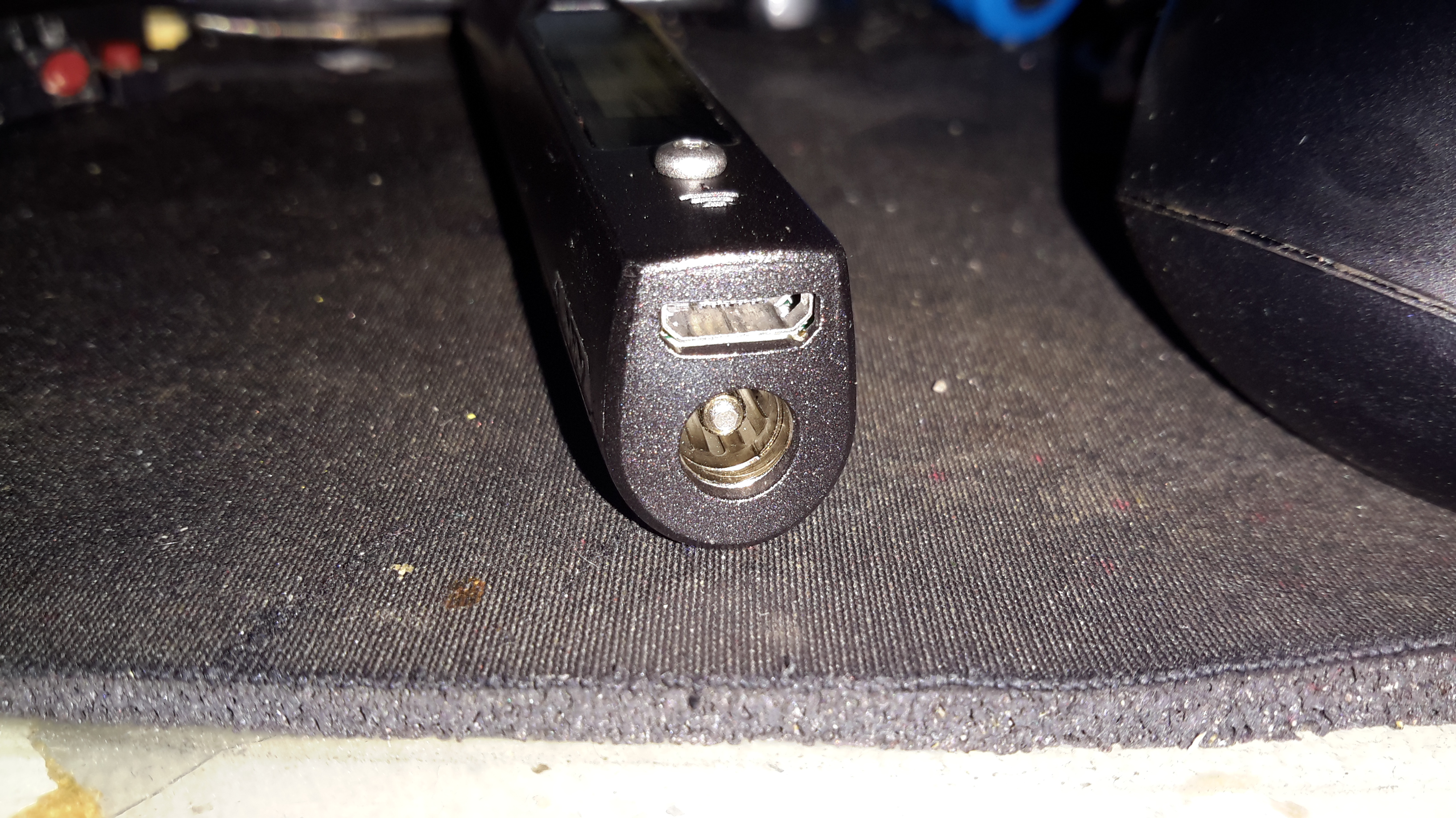
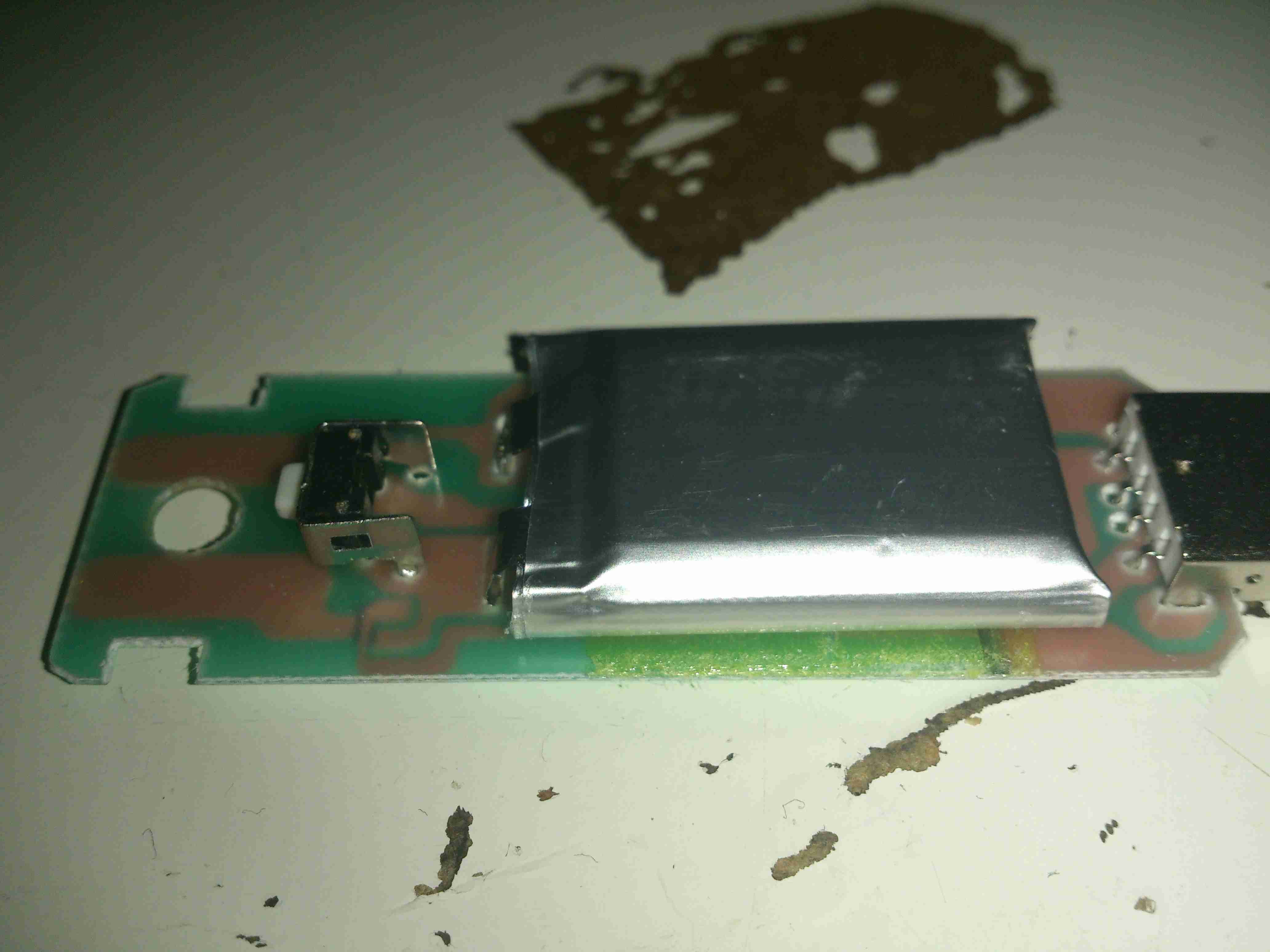
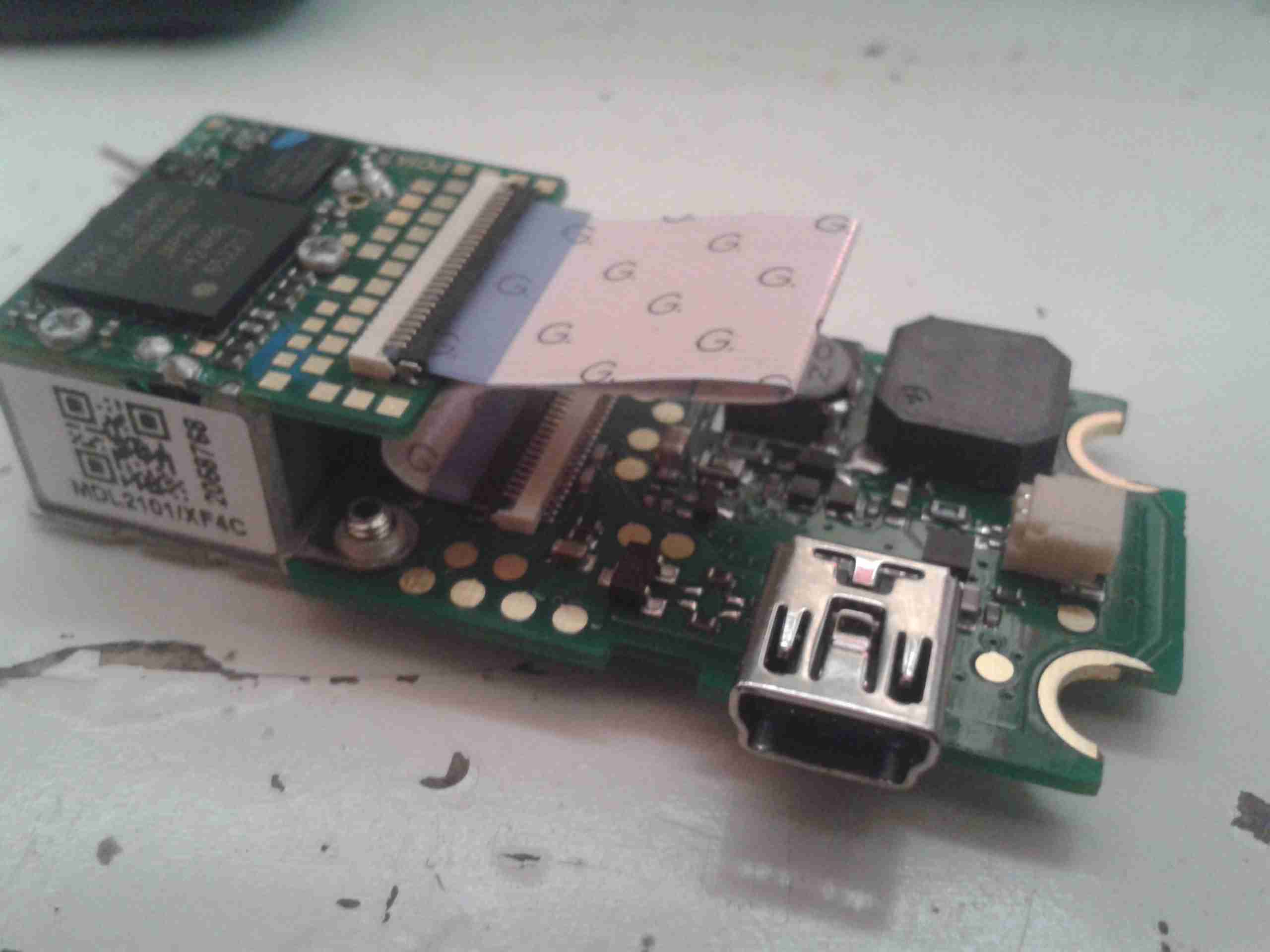
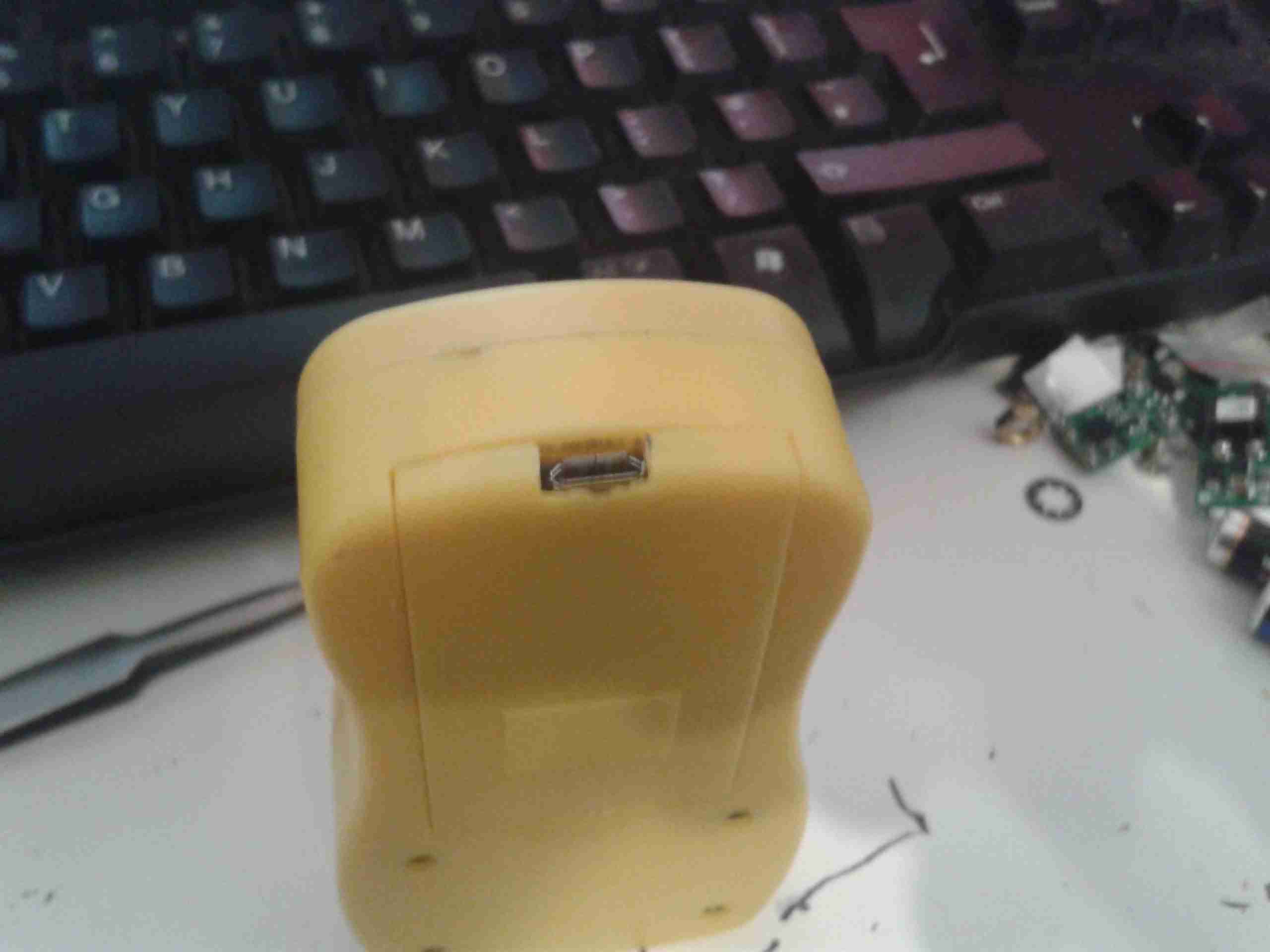
Down the sides are the user interface buttons, and here the Micro-B input connector. The 4-pin header is visible here that takes serial data down to the bluetooth section.

USB-C Connectors
USB-C Connectors

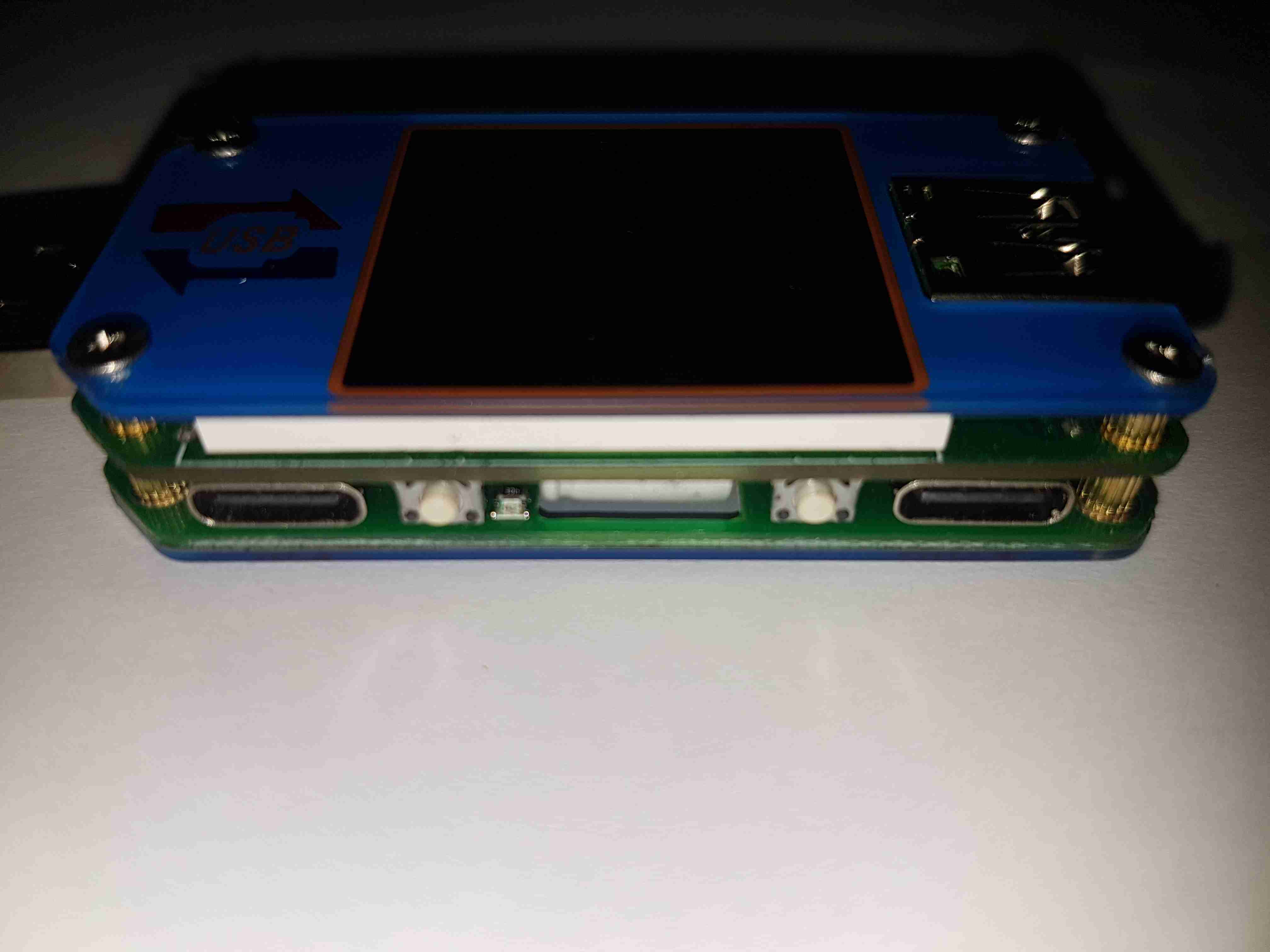
The other side has the remaining pair of buttons, and the USB-C I/O. I don’t yet own anything USB-C based, but this is good future proofing.

LCD Display
LCD Display

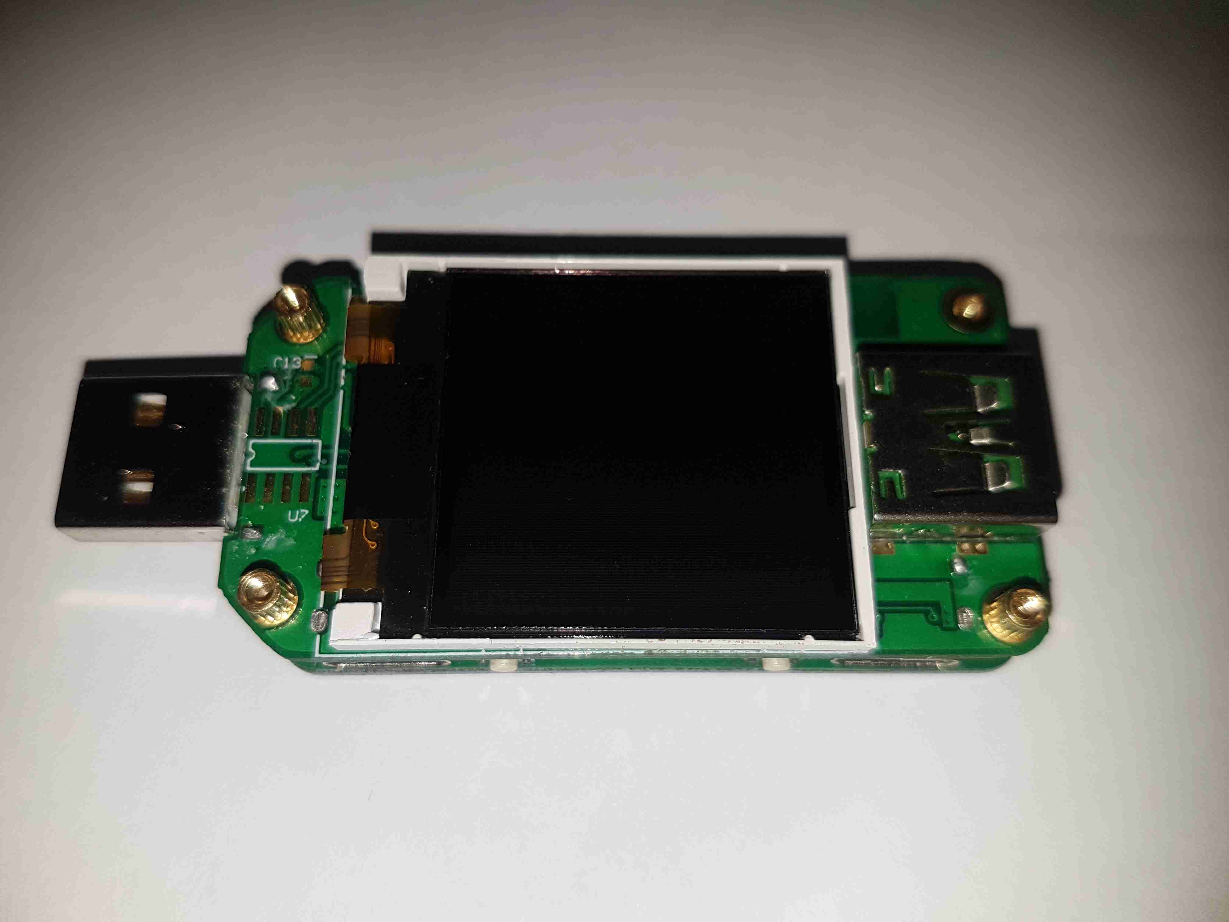
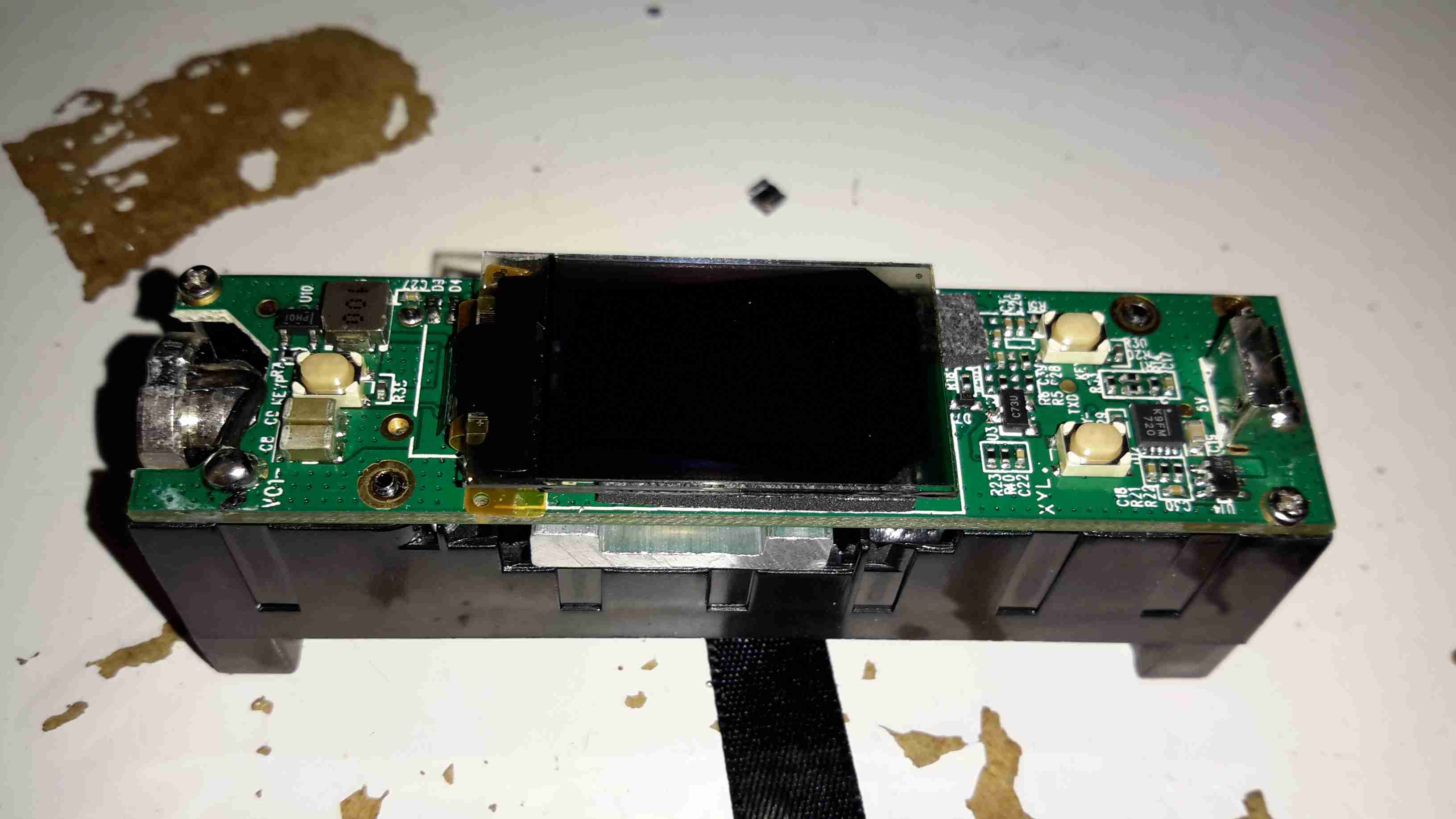
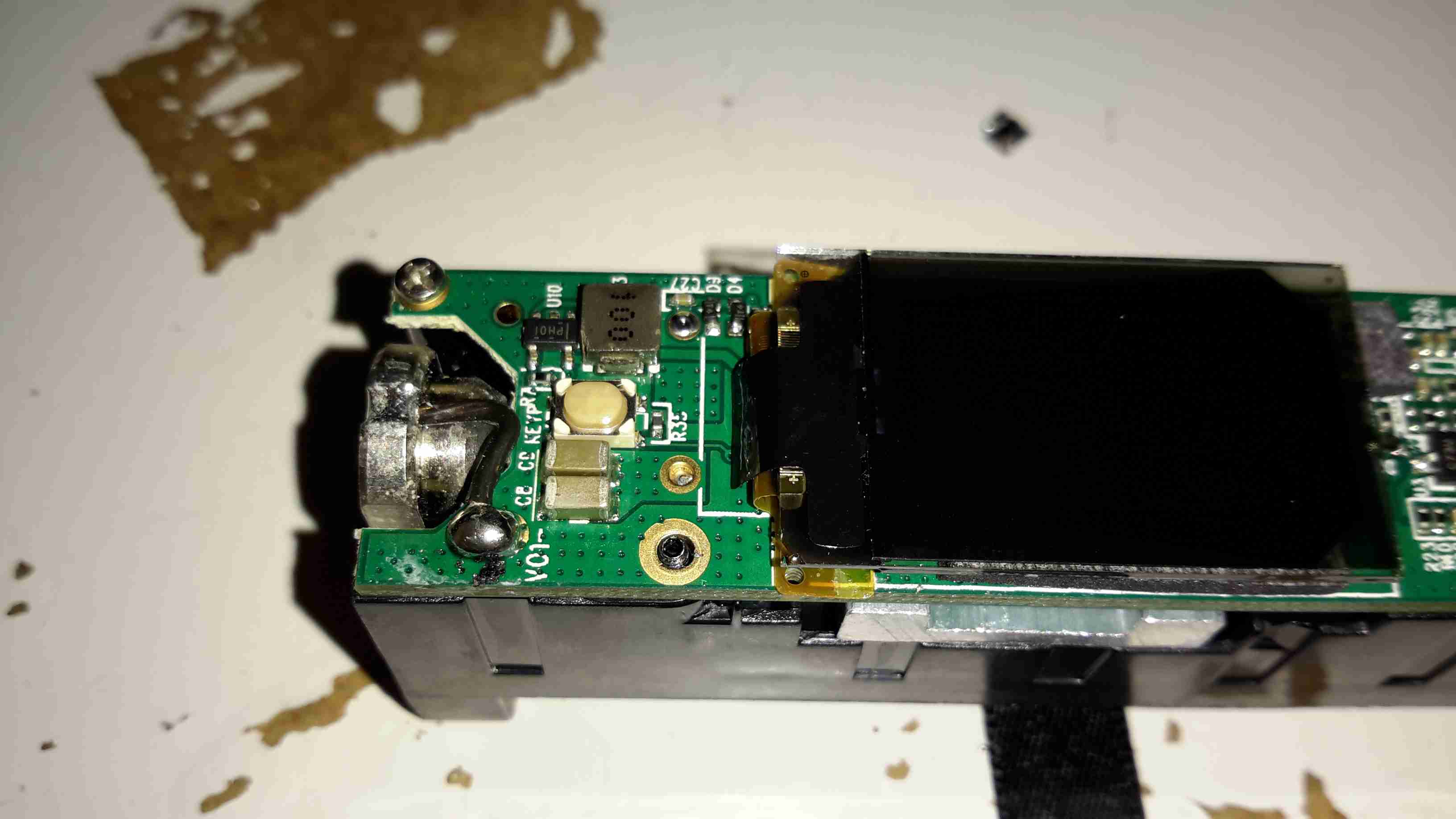
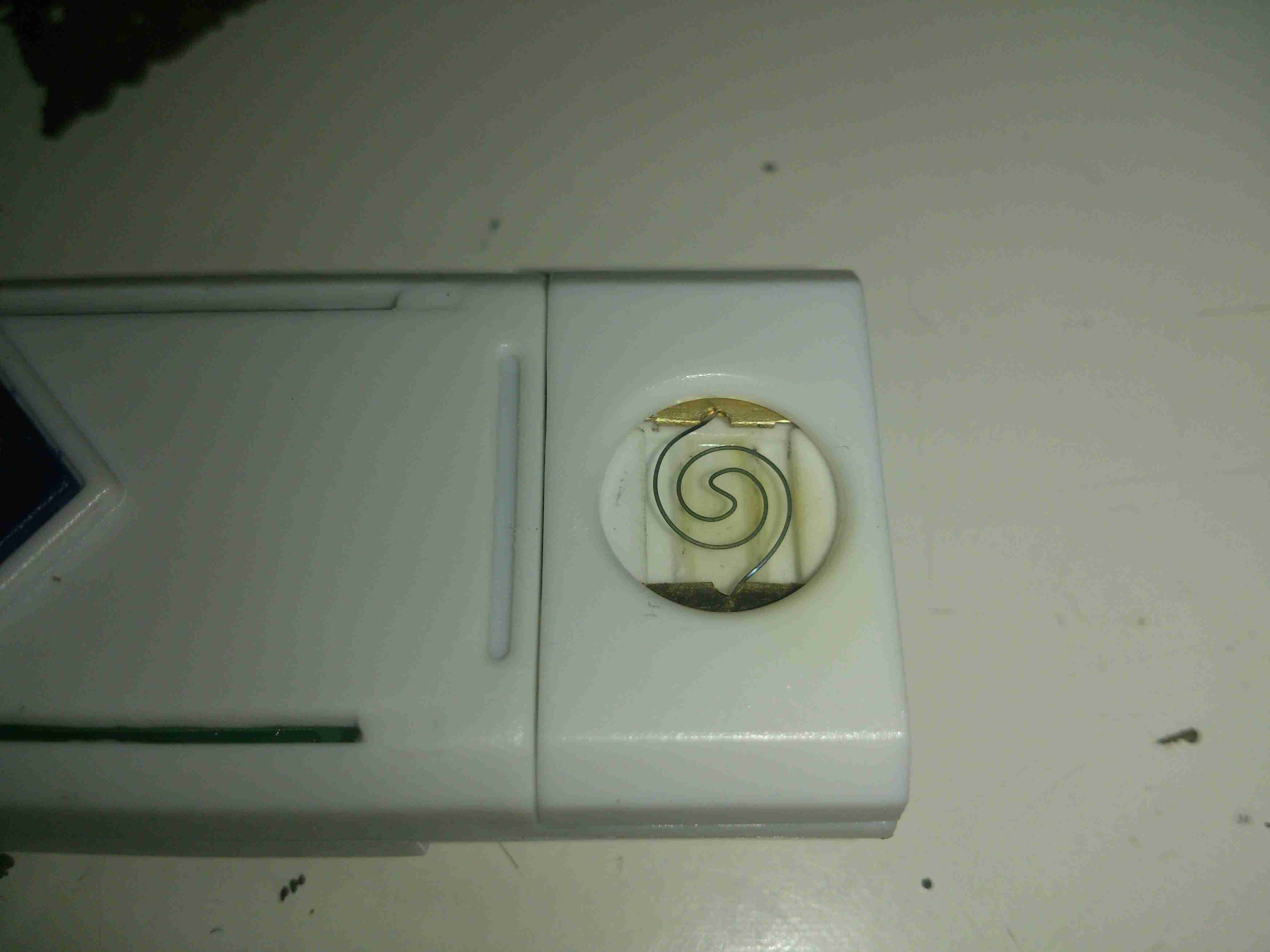
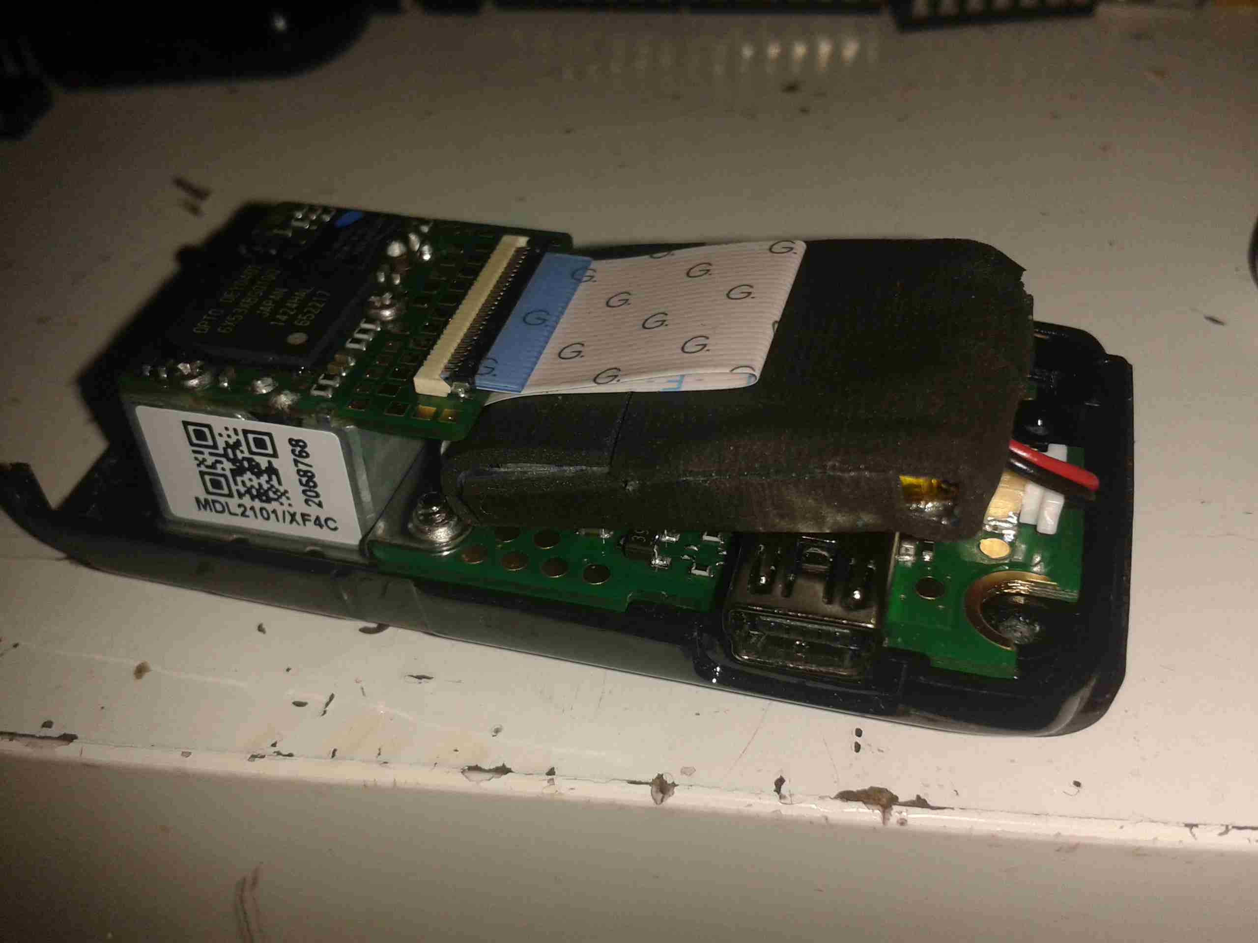
Removing the top plastic cover plate reveals the small 1″ TFT LCD module. This will be hot-bar soldered underneath the screen. There’s an unused footprint next to the USB input connector, judging by the pin layout it’s probably for a I²C EEPROM.

Main Board Components

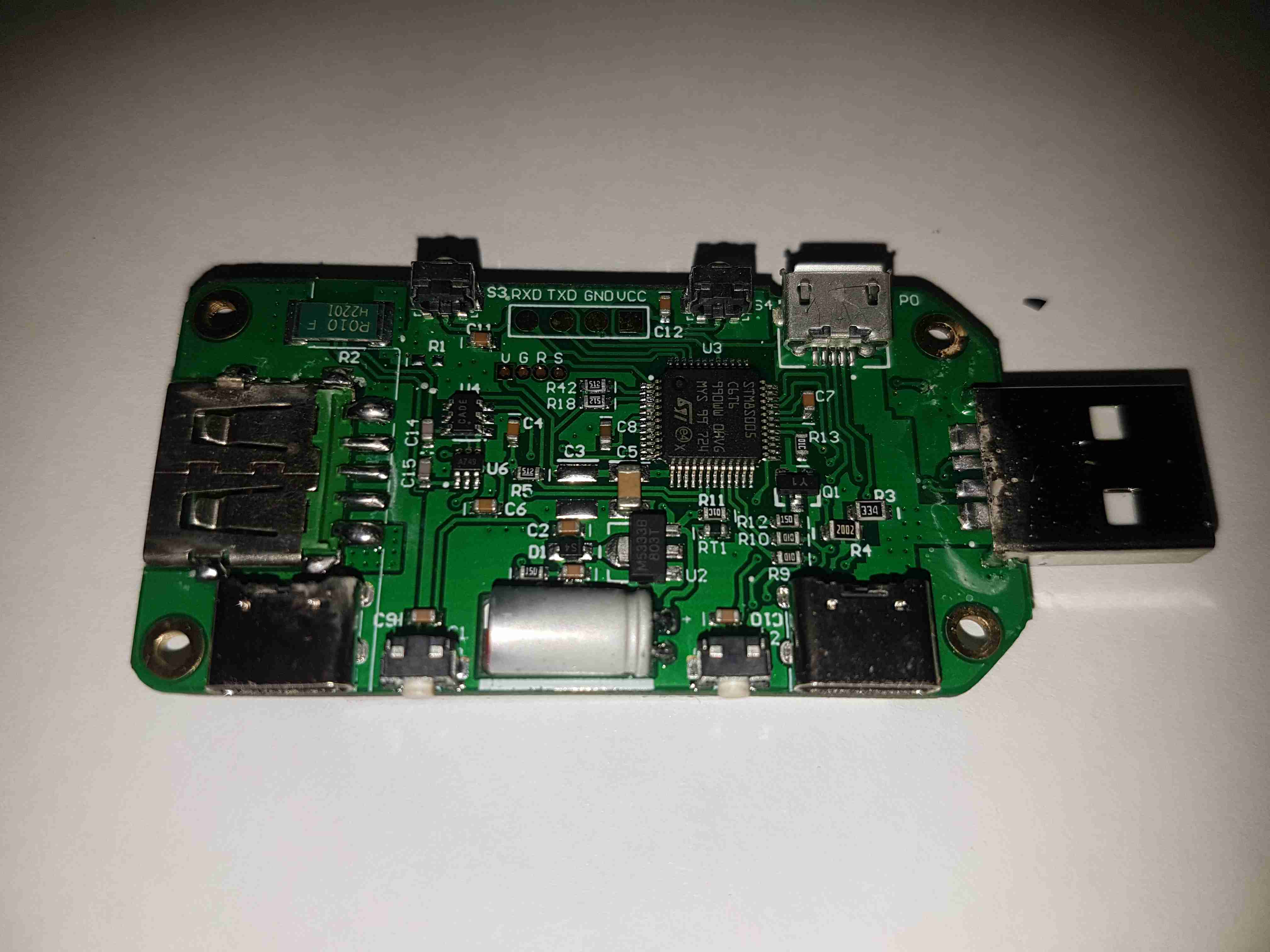
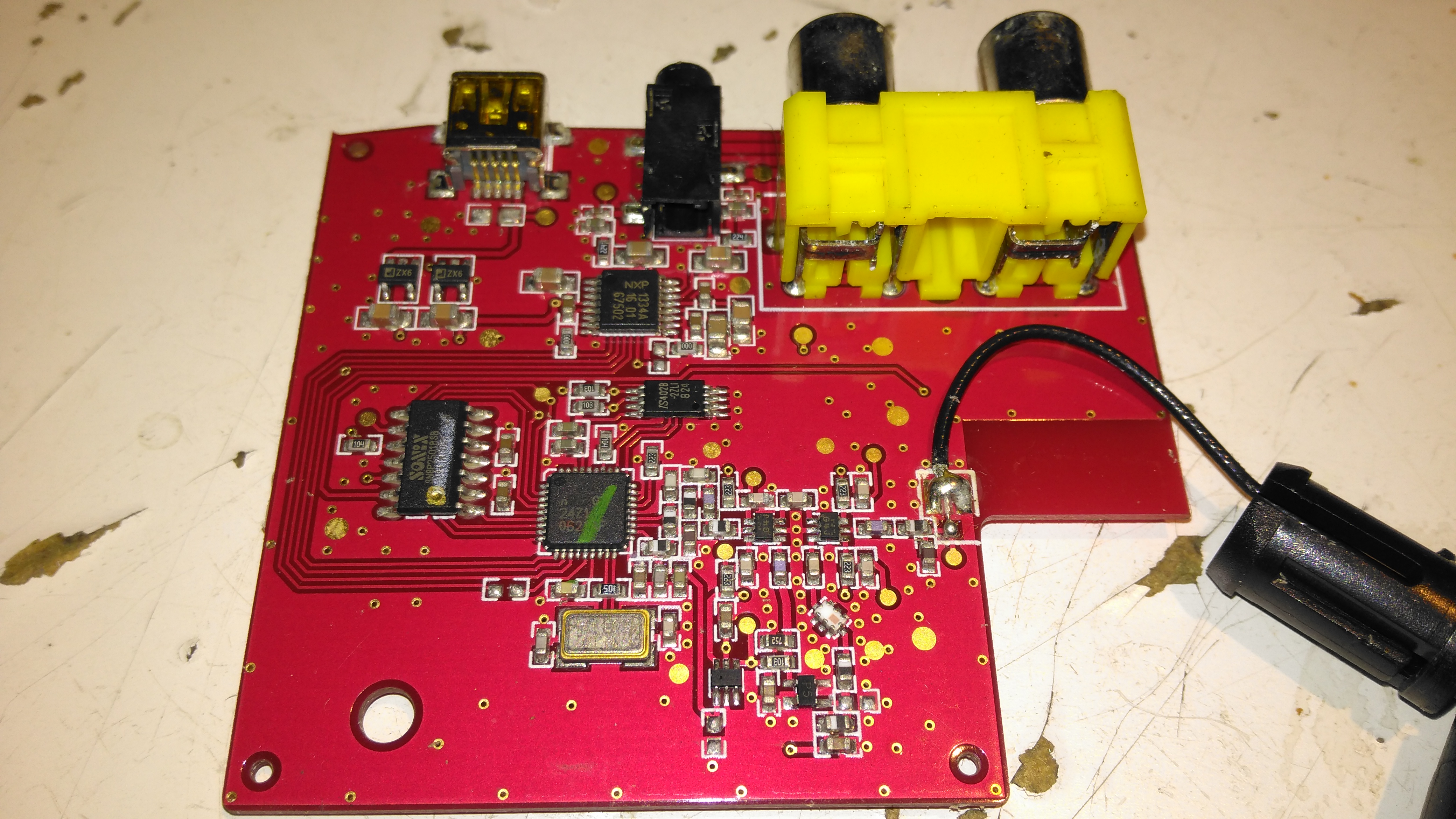
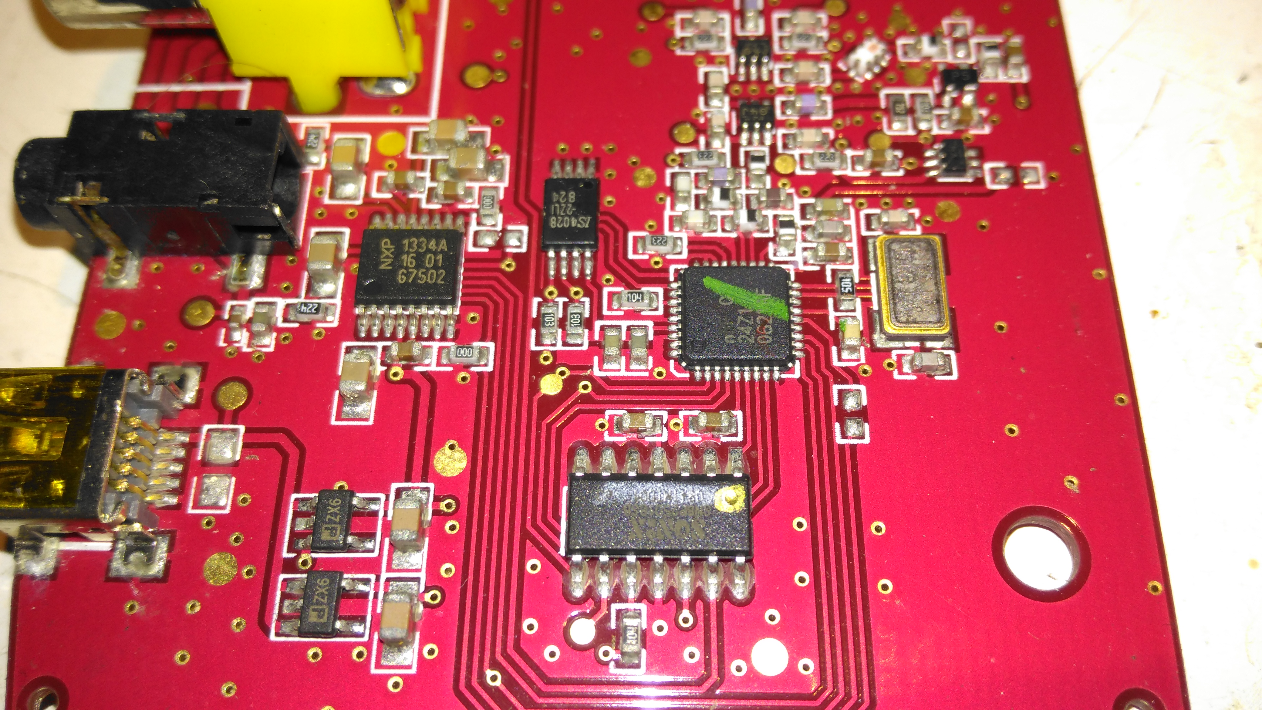
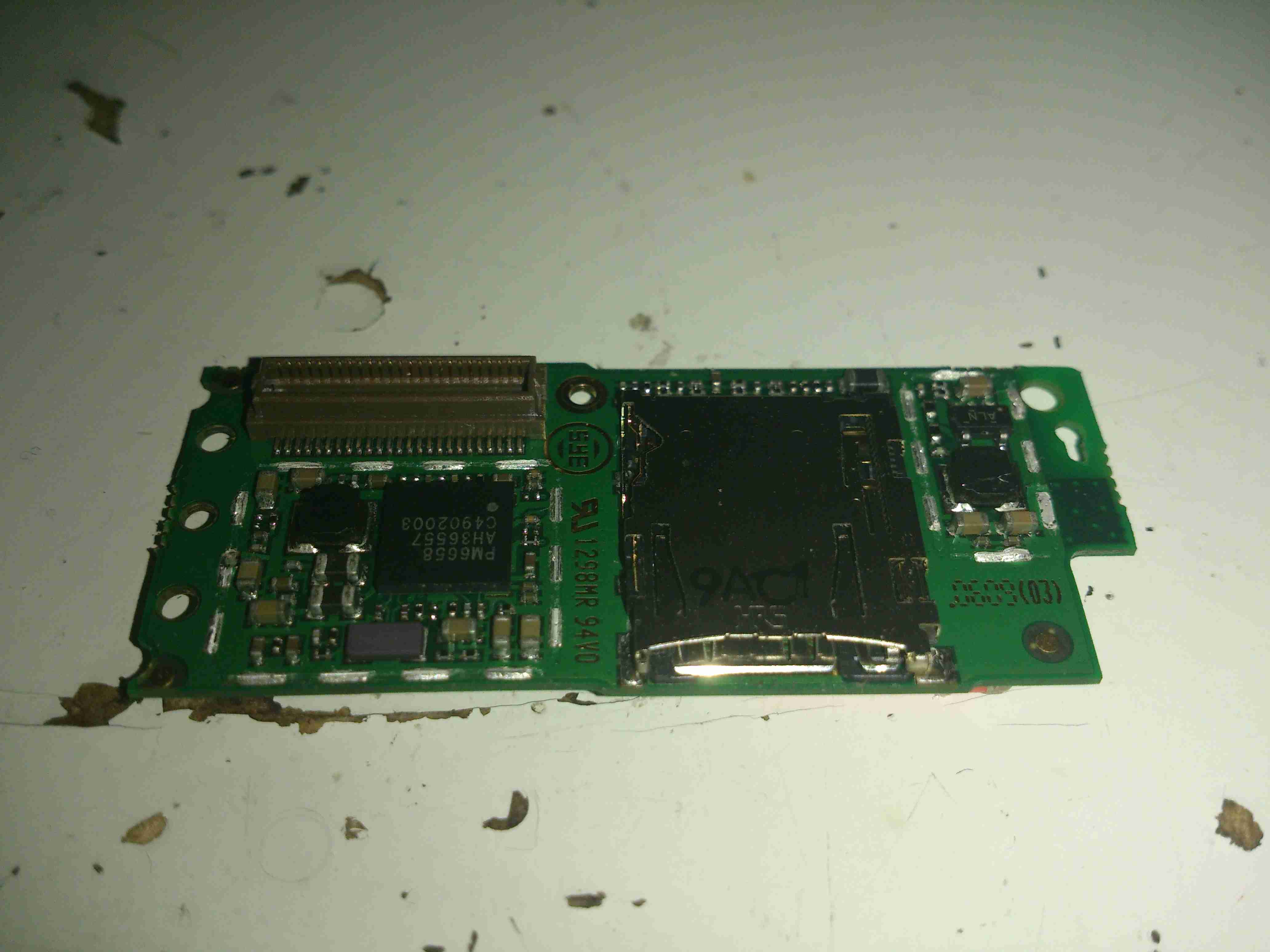
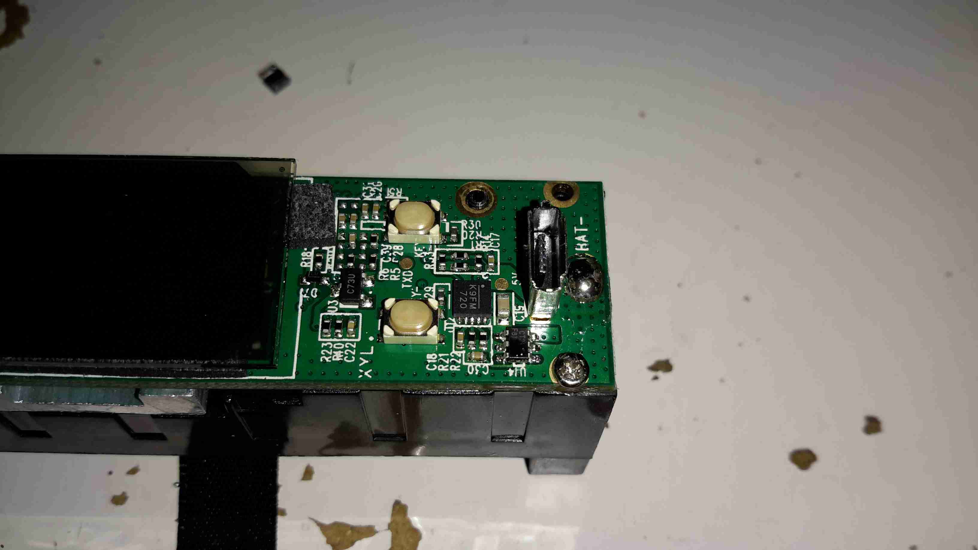
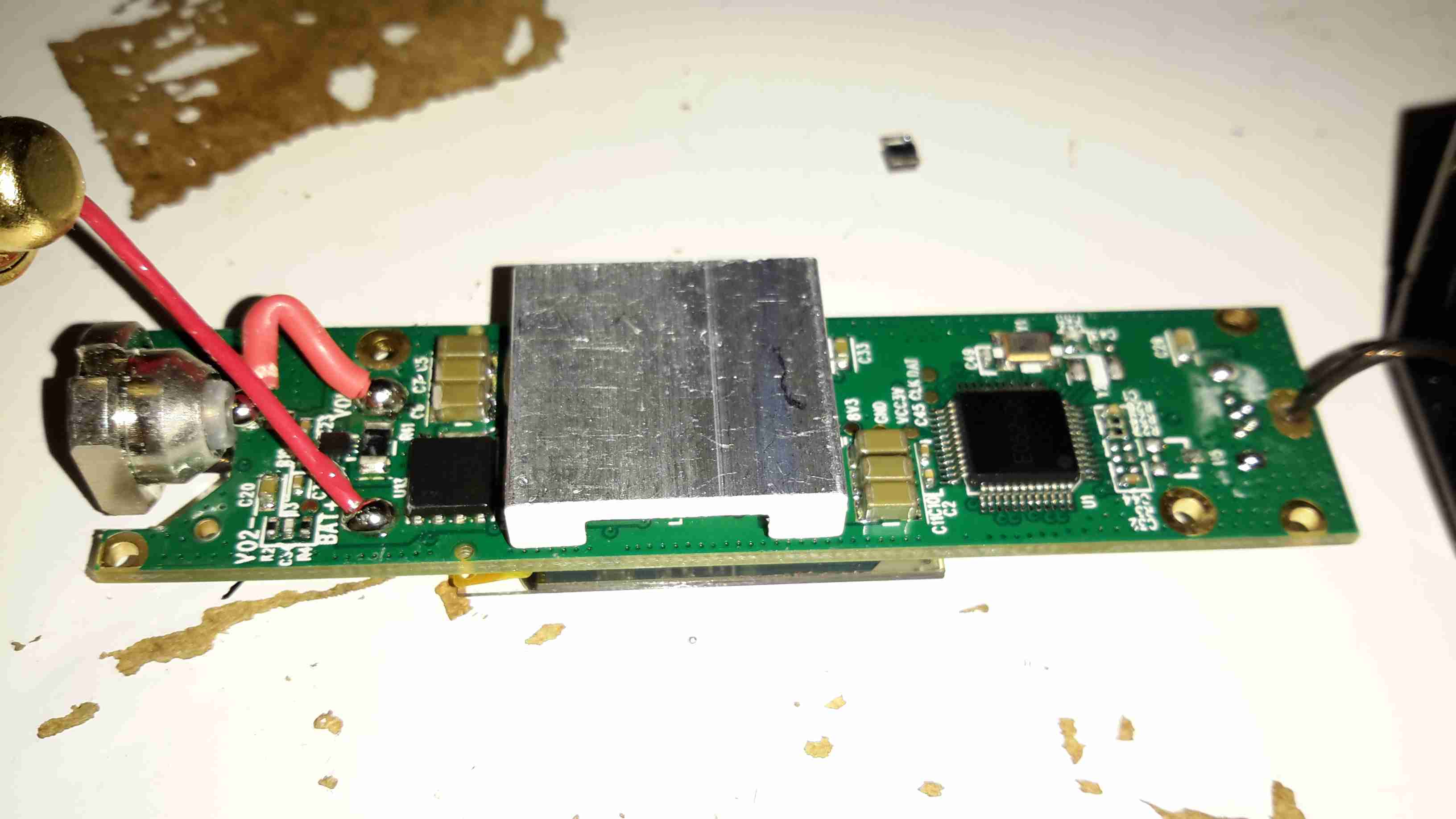
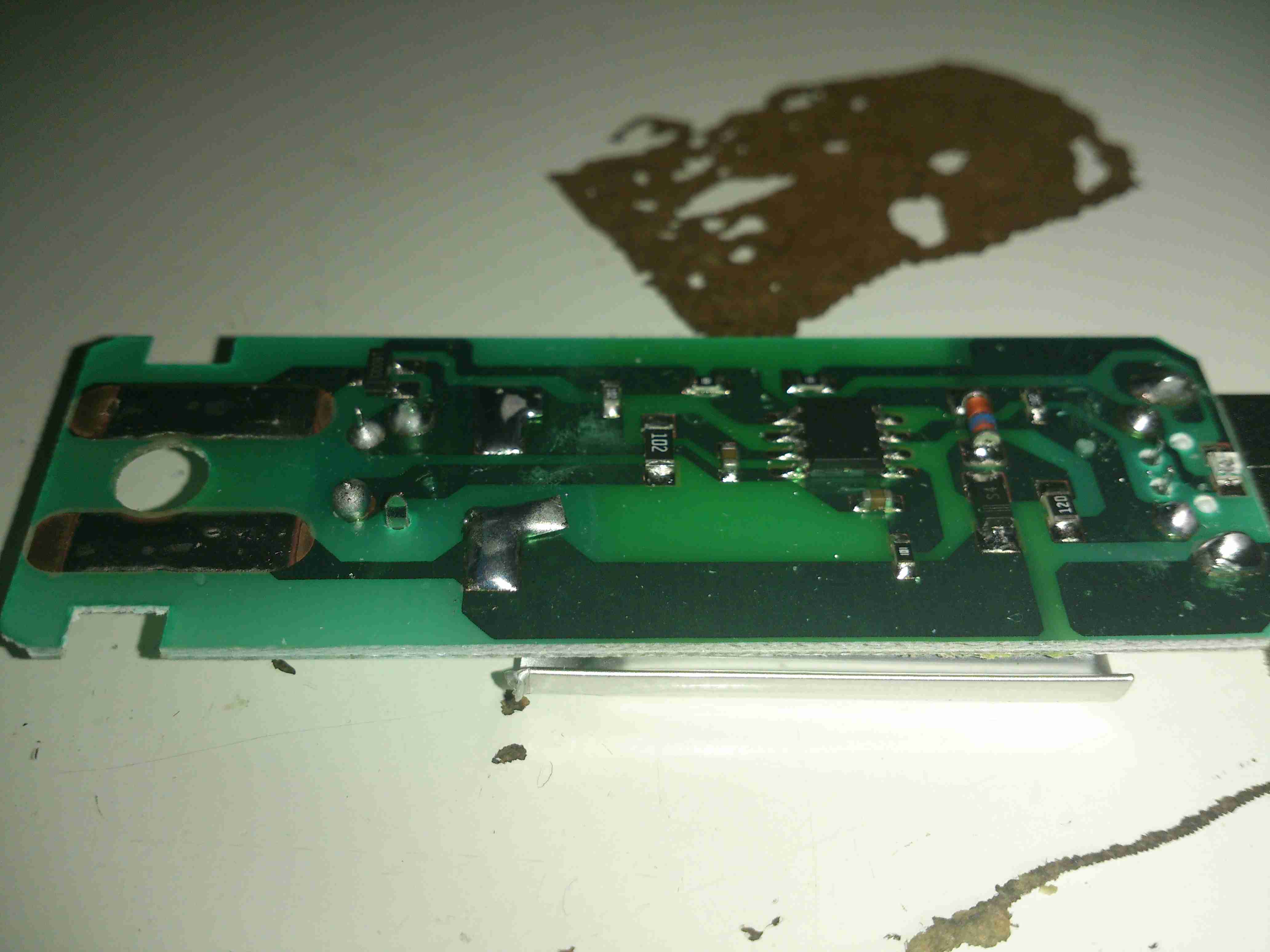
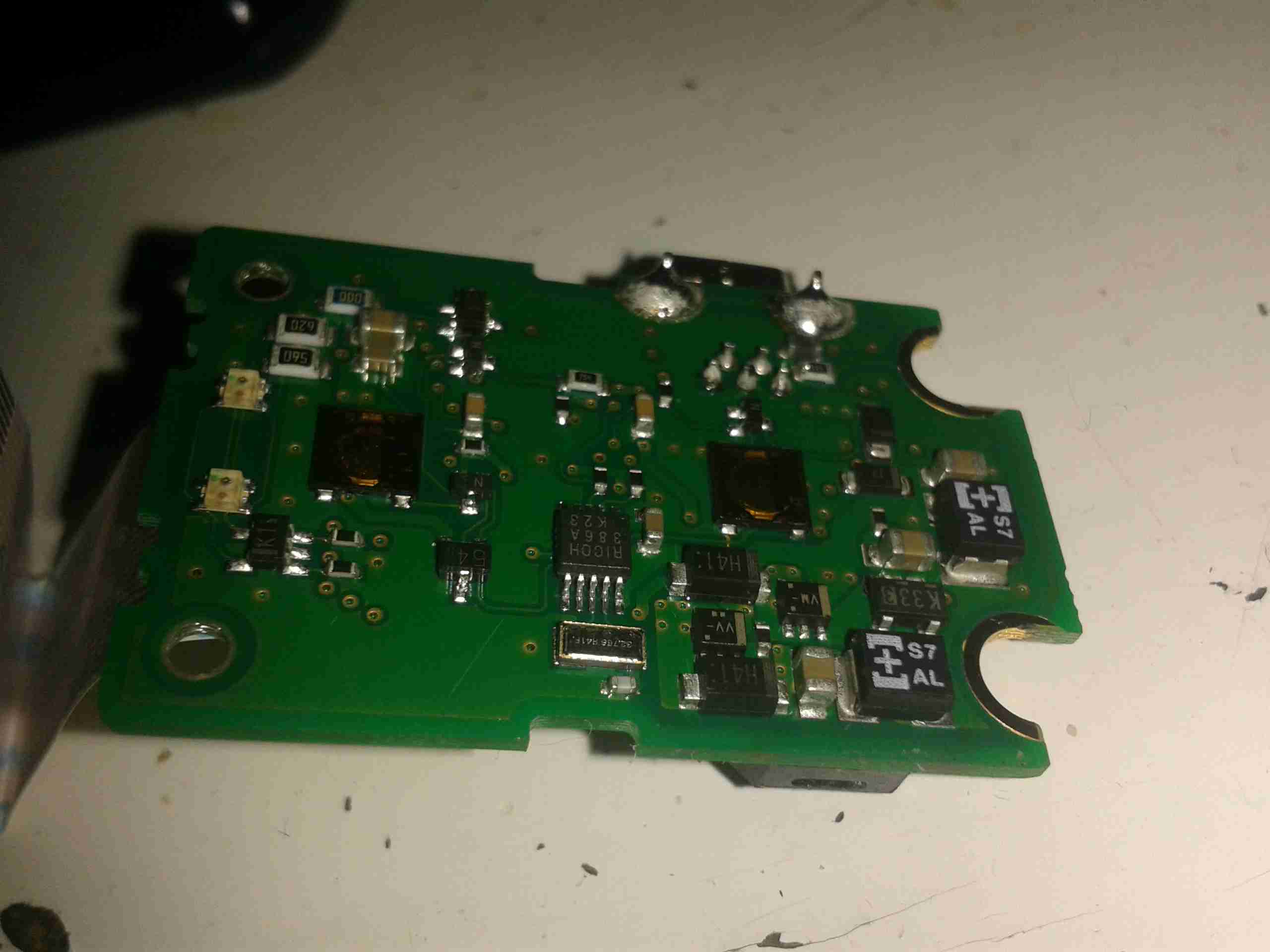
The underside of the top PCB has all the main components. The brains of the operation is a ST STM8S005C6T6 microcontroller. It’s at the basic end of the STM range, with a 16MHz clock, 32K flash, EEPROM, 10-bit ADC, SPI, UART & I²C. The main 0.010Ω current shunt is placed at the top left of the board in the negative rail. A couple of SOT-23 components in the centre of the board, I haven’t been able to identify properly, but I think they may be MOSFETs. The large electrolytic filter capacitor has a slot routed into the PCB to allow it to be laid flat. Providing the main power rail is a SOT-89 M5333B 3.3v LDO regulator.

Bluetooth Radio
Bluetooth Radio

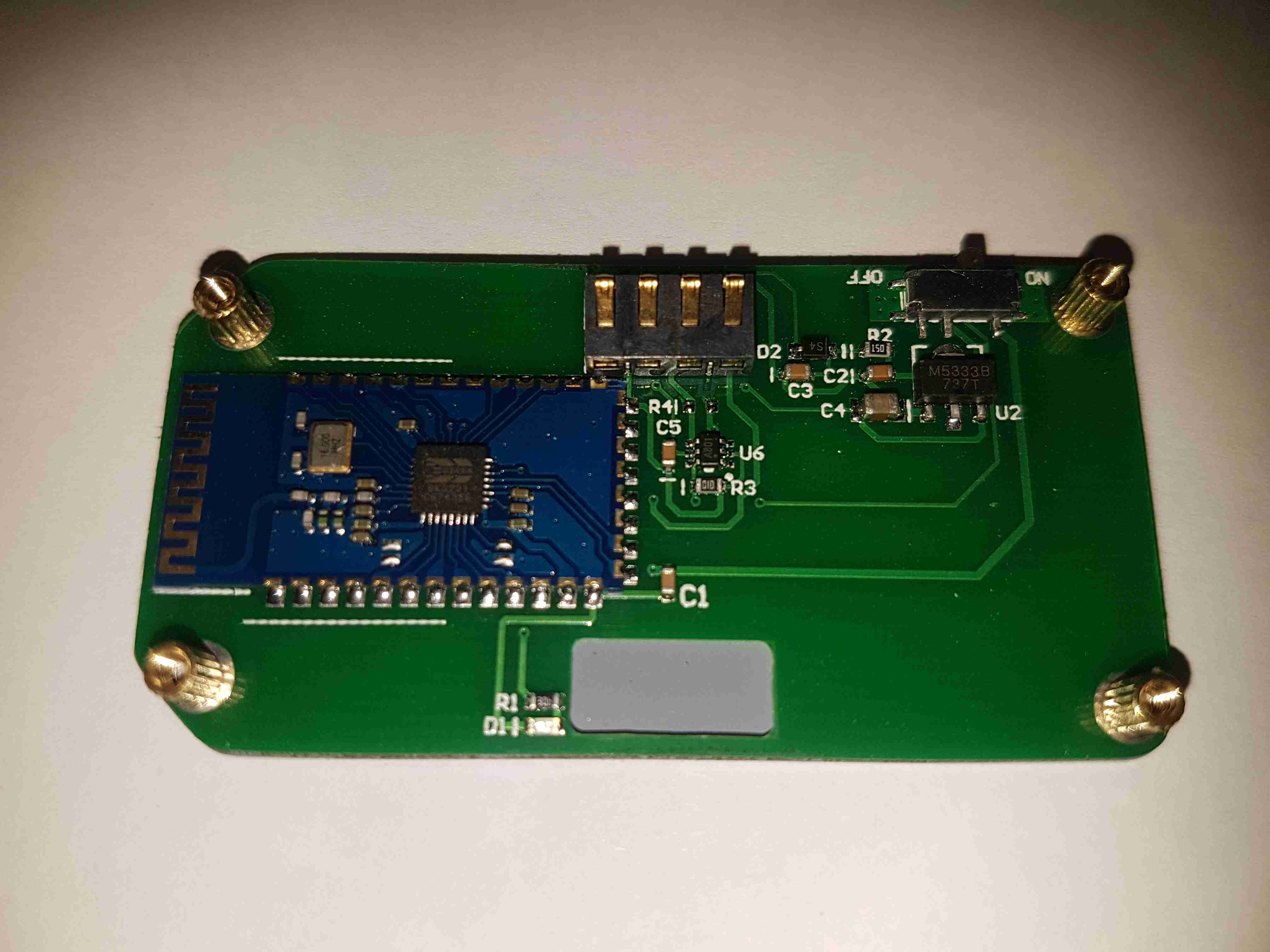
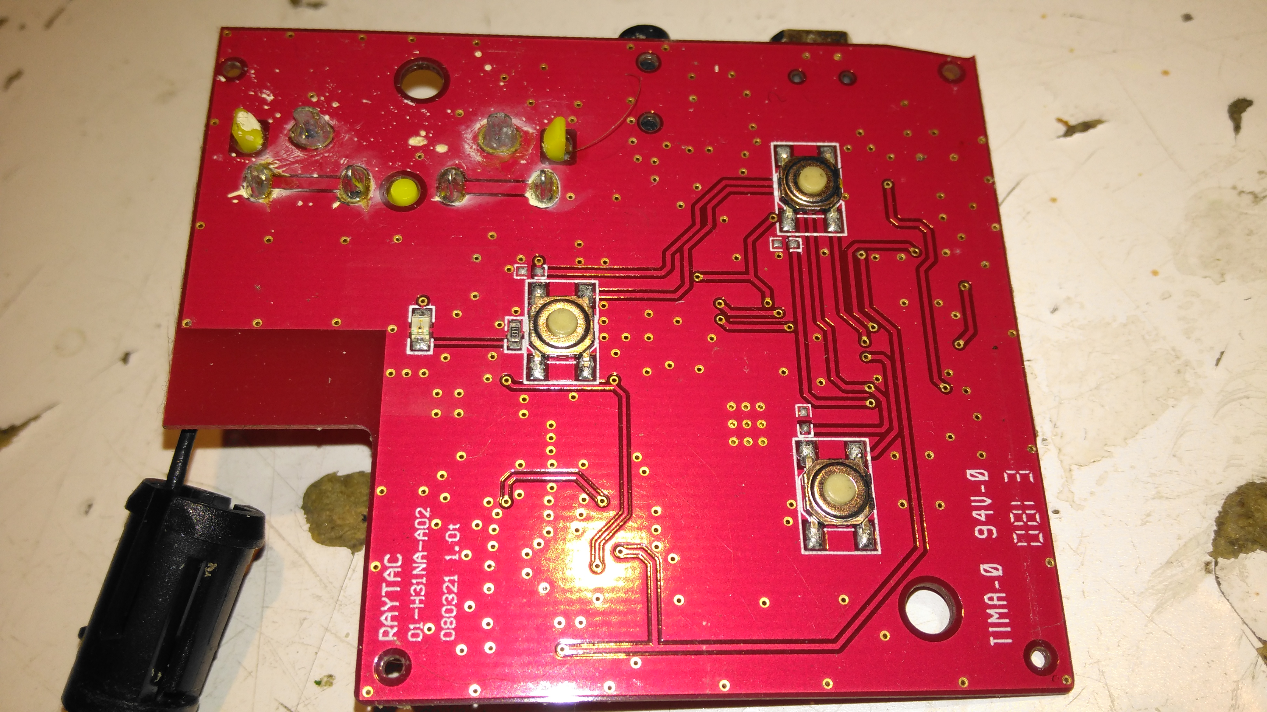
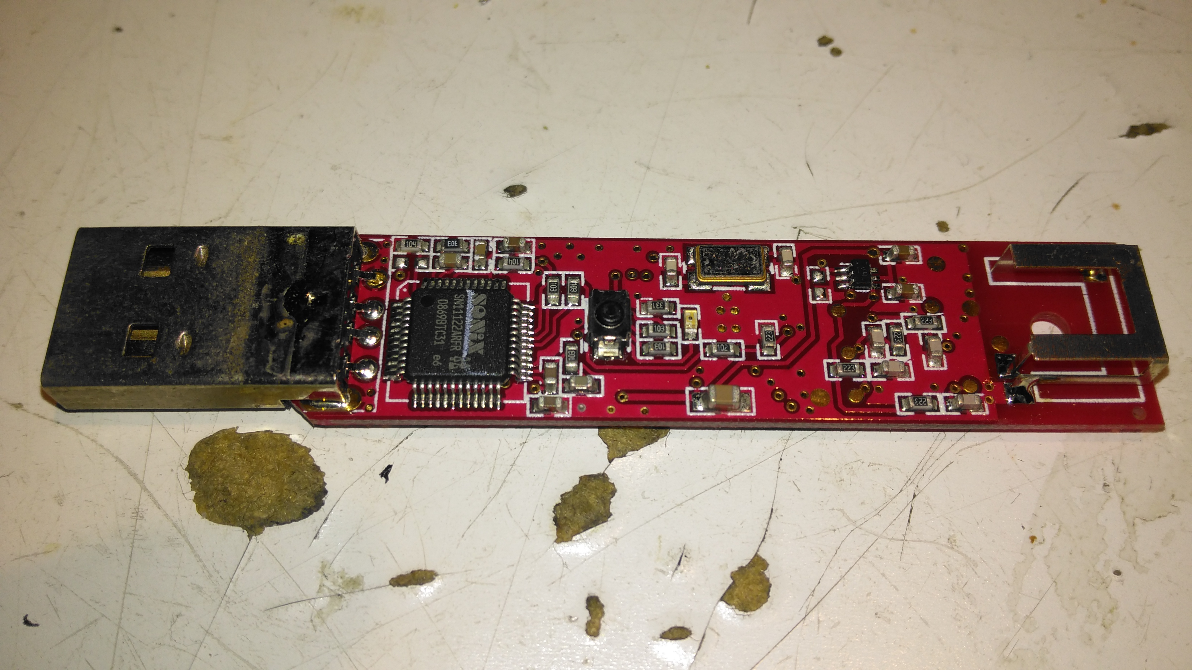
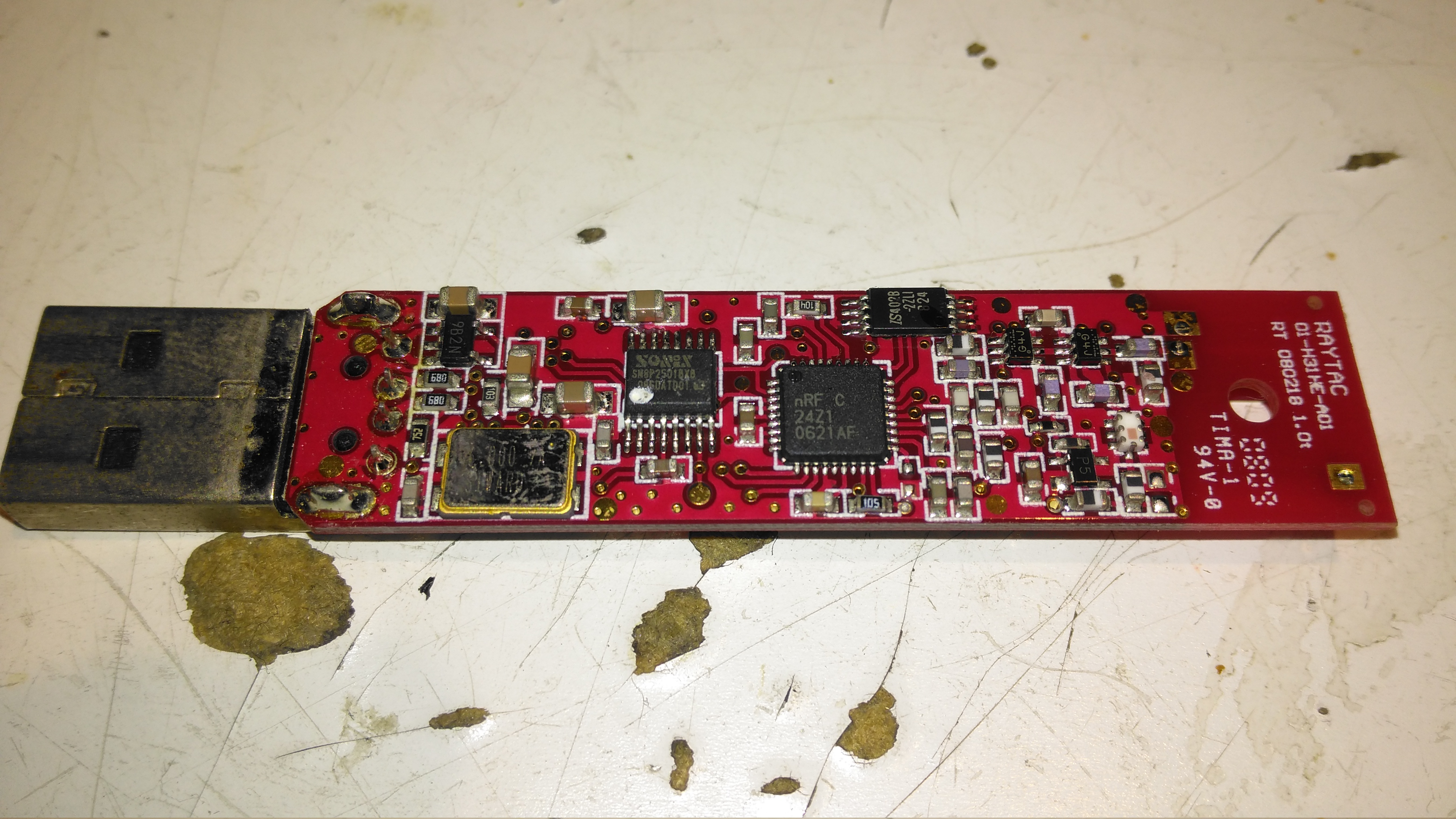
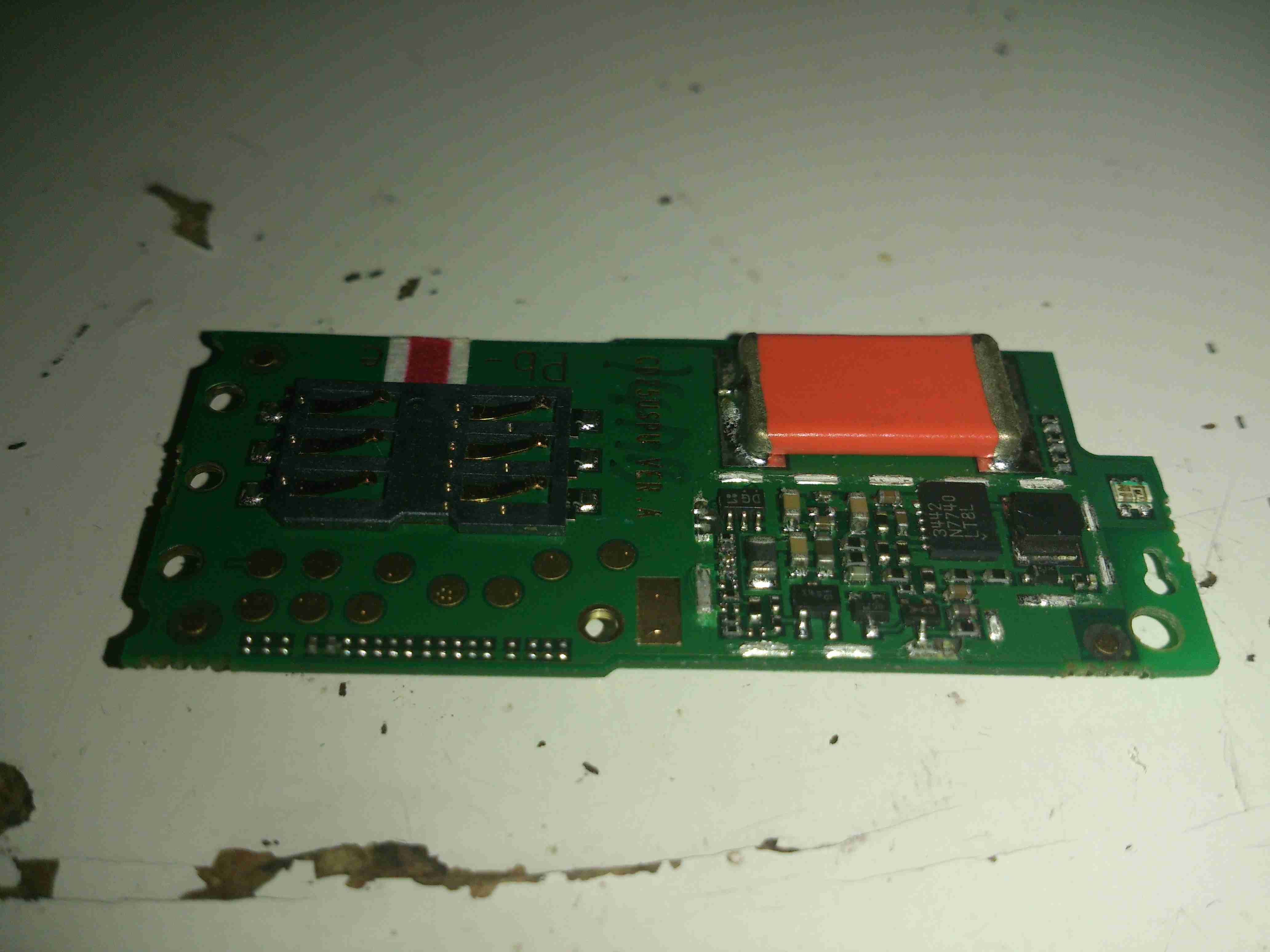
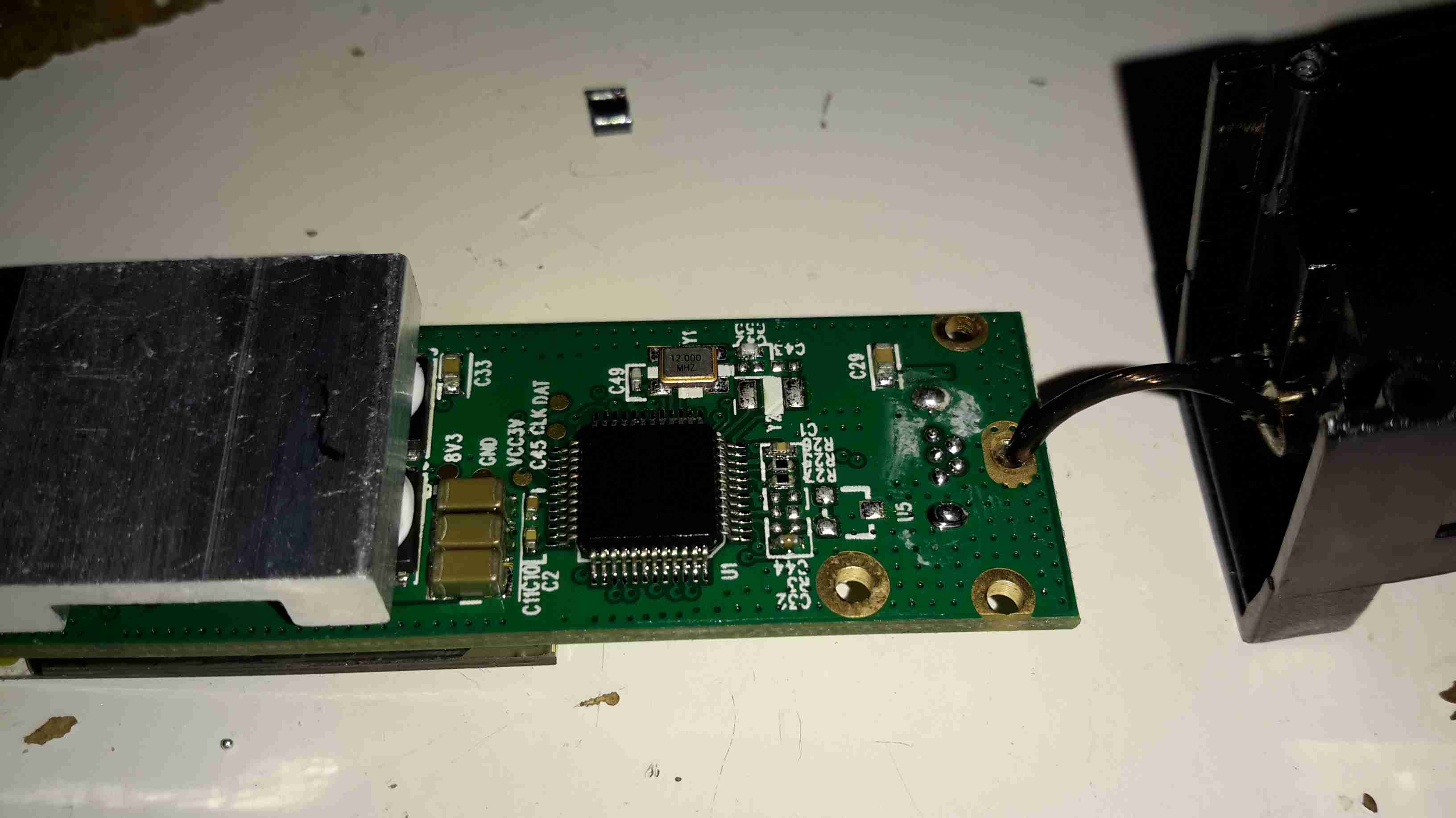
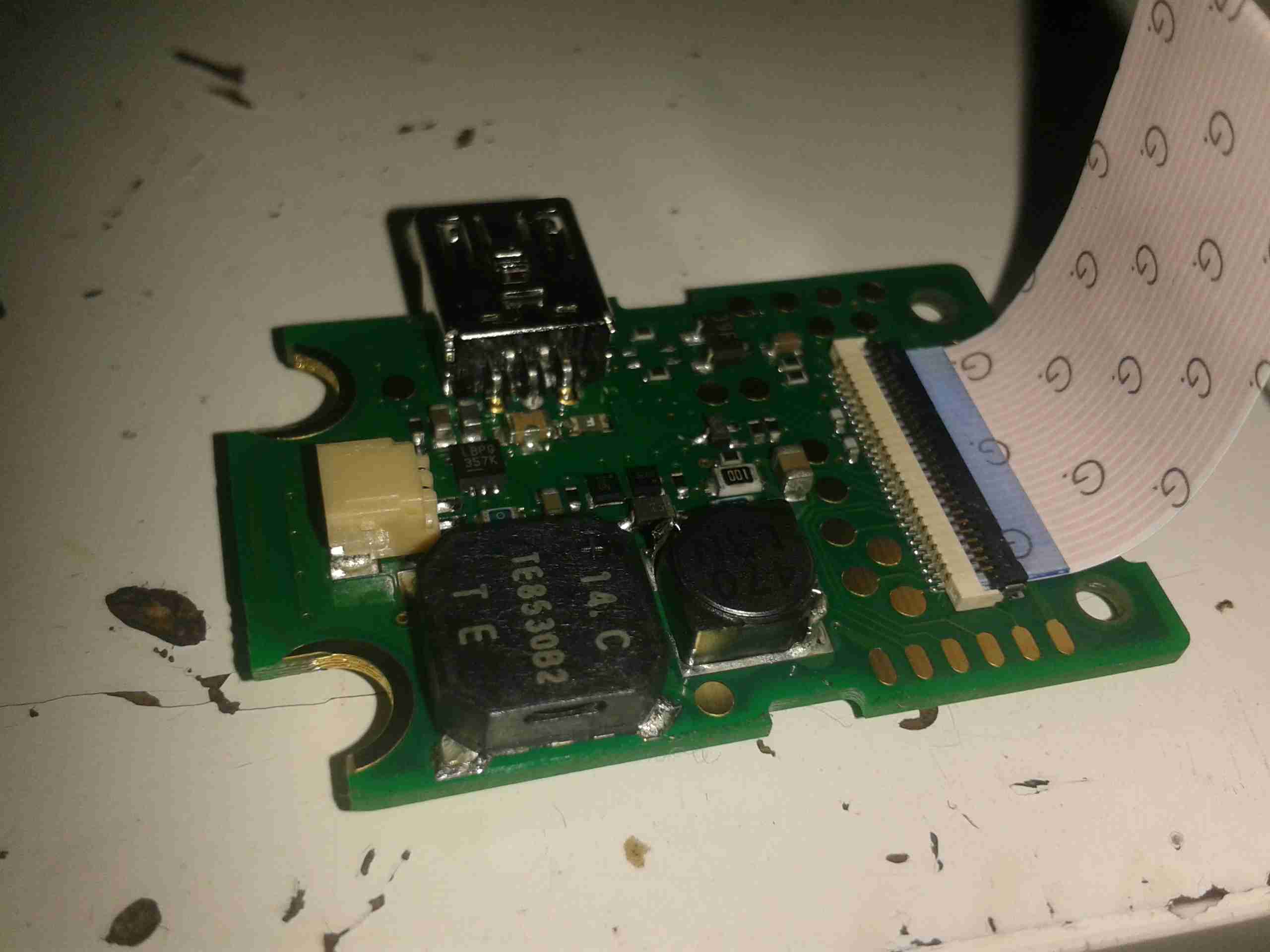
The bottom board contains the bluetooth radio module, this is a BK3231 Bluetooth HID SoC. The only profile advertised by this unit is a serial port. There’s a local 3.3v LDO regulator & support components, along with an indicator LED.

Posted on 2 Comments

Maplin A24GU Wireless Audio Module Teardown

Transmitter
Transmitter

This is a pair of modules that Maplin was selling some time back, to send stereo audio over a 2.4GHz radio link. The transmitter identifies as a USB sound card, I’ve personally used these units to transmit audio about 60ft. The transmitter, above, has a single button for pairing with the receiver below.

Receiver
Receiver

The receiver unit has a large external antenna, a link status LED & volume buttons, these directly control the volume level on the host PC via the sound card drivers.

Receiver PCB Top
Receiver PCB Top

Popping the case open on the receiver reveals a large PCB, holding the chipset, along with the audio output jacks & Mini-USB power input. The antenna Coax is soldered to the PCB.

Receiver PCB Bottom
Receiver PCB Bottom

The top of the board has the control buttons, and the status LED.

Receiver Chipset
Receiver Chipset

The chipset used here is a Nordic Semiconductor nRF20Z01 2.4GHz Stereo Audio Streamer, there’s a small microcontroller which does all the register magic on the RF transceiver. The RF chain is at the top of the photo, audio outputs on the top left, and the micro USB power input & voltage regulators at bottom left.

Transmitter PCB Top
Transmitter PCB Top

The transmitter PCB has a Sonix USB Audio Codec, to interface with the host PC. This is then fed into another Nordic Semi part on the opposite side of the board:

Transmitter PCB Bottom

The bottom of the transmitter has the RF section, and another small control microcontroller.

Posted on 11 Comments

Jaguar S-Type Aux Heater / Webasto Thermo Top V Part 2 – W-Bus Diagnostics

As I mentioned in the previous post, these heaters have a standard interface that’s used for control & diagnostics, the W-Bus. This is transmitted over the K-Line of the vehicle bus, and all heaters, regardless of firmware modifications done by the various car manufacturers respond to this interface. Official Webasto diagnostic adaptors are available, but these are just a very expensive serial adaptor. A much cheaper option is a ~£5 Universal ODB adaptor.

ODB2
ODB2

Above shows the signals on the ODB connector – the ones we’re interested in here are Pin 16, the +12v supply, and Pin 7, K-Line. Connect Pin 16 to the positive supply to the heater, and Pin 7 to Pin 2 on the Webasto heater. (Valid for all TT-V heaters).

Device Selection
Device Selection

Once these two connections are made to the heater, fire up the Thermo Test software. The screen above will be displayed. Pick W-Bus at top left.

COM Port Selection
COM Port Selection

First thing, connect the ODB adaptor to USB, and change to the correct COM port in Thermo Test. There may be several in the list, but a newly connected USB device should show up with the highest COM number.

Thermo Test
Thermo Test

Once Thermo Test is running, start communications by going to the Diagnosis Menu > Start Diagnostic (F2 keyboard shortcut).

Initialized
Initialized

After a few seconds, communication will be established. This will show faults, if any are present, and allow testing of the heater & it’s component parts. A summary report can be generated with Diagnosis > View Summary:

This shows all the important stuff, including running hours. (5388Hrs on this heater!). Most importantly, there are no faults listed.

Heater Running
Heater Running

The heater can be fully tested by issuing a start command from the Command Menu > Parking Heating option. Obviously cooling water will be required for this, along with an external water pump. (The water pump control output on these heaters seems to be totally disabled in firmware, as they rely on the engine’s coolant pump). I used a bucket of water along with a small centrifugal pump to provide the cooling. During this test I noted that the firmware is much more aggressive in these units. The marine versions shut down at ~72°C water temperature, whereas these don’t so the same until ~90°C.

Now I’ve managed to communicate with the heater, I’ll get onto building a standalone controller so I can dispense with the Windows VM for control.

Posted on Leave a comment

AIX Gigabit Ethernet To USB Bridge

USB To Ethernet
USB To Ethernet

Here’s a chap eBay USB-To-Ethernet dongle I obtained for use with the Raspberry Pi Zero. This one is getting torn down permanently, as it’s rather unreliable. It seems to like having random fits where it’ll not enumerate on the USB bus. The silicon in the ICs will eventually make it here once I manage to get a new microscope 😉

Main Chipset
Main Chipset

This is quite a heavily packed PCB, with the main Asix AX88178 on the left. This IC contains all of the logic for implementing the Ethernet link over USB, except the PHY. It’s clock crystal is in the top left corner.

Reverse Side
Reverse Side

Not much on the reverse side, there’s a 3.3v linear regulator at top left, the SOIC is an Atmel AT93C66A 4KB EEPROM for configuration data.

Vitesse PHY
Vitesse PHY

The final IC in the chain is the Vitesse VSC8211 Gigabit PHY, with it’s clock crystal below. This interfaces the Ethernet MAC in the Asix IC to the magjack on the right.

Posted on Leave a comment

eBay Special – LED Disco Light With Built In MP3 Player

Here’s an eBay oddity – it’s got the same light & lens mechanism as the cheap “disco light” style bulbs on eBay, but this one is battery powered & has a built in MP3 player.

MP3 Disco Light
MP3 Disco Light

This device simply oozes cheapness. The large 4″ plastic dome lens sits on the top above the cheap plastic moulding as a base, which also contains the MP3 player speaker.

Controls
Controls

There are few controls on this player, the volume buttons are combined with the skip track buttons, a long press operates the volume control, while a short press skips the tracks. Several options for getting this thing to play music are provided:

  • Bluetooth – Allows connection from any device for bluetooth audio
  • USB – Plugging in a USB flash drive with MP3 files
  • SD Card – Very similar to the USB flash drive option, just a FAT32 formatted card with MP3 files
  • Aux – There’s no 3.5mm jack on this unit for an audio input, instead a “special” USB cable is supplied that is both used to charge the built in battery & feed an audio signal. This is possible since the data lines on the port aren’t used. But it’s certainly out of the ordinary.
Top Removed
Top Removed

The top comes off with the removal of a single screw in the centre of the lens. The shaft in the centre that holds the lens is attached to a small gear motor under the LED PCB. There’s 6 LEDs on the board, to form an RGB array. Surprisingly for a very small battery powered unit these are bright to the point of being utterly offensive.

Mainboard
Mainboard

Here’s the mainboard removed from the plastic base. There’s not much to this device, even with all the options it has. The power switch is on the left, followed by the Mini-B USB charging port & aux audio input. The USB A port for a flash drive is next, finishing with the µSD slot. I’m not sure what the red wire is for on the left, it connects to one of the pins on the USB port & then goes nowhere.

Audio Amplifier
Audio Amplifier

The audio amplifier is a YX8002D, I couldn’t find a datasheet for this, but it’s probably Class D.

Main Chipset
Main Chipset

Finally there’s the main IC, which is an AC1542D88038. I’ve not been able to find any data on this part either, it’s either a dedicated MP3 player with Bluetooth radio built in, or an MCU of some kind.The RF antenna for the Bluetooth mode is at the top of the board.
Just behind the power switch is a SOT23-6 component, which should be the charger for the built in Lithium Ion cell.

Lithium Ion Cell
Lithium Ion Cell

The cell itself is a prismatic type rated in the instructions at 600mAh, however my 1C discharge test gave a reading of 820mAh, which is unusual for anything Li-Ion based that comes from eBay 😉
There is cell protection provided, it’s under the black tape on the end, nothing special here.

The main issue so far with this little player is the utterly abysmal battery life – at full volume playing MP3s from a SD card, the unit’s current draw is 600mA, with the seizure & blindness-inducing LEDs added on top, the draw goes up to about 1200mA. The built in charger is also not able to keep up with running the player while charging. This in all only gives a battery life of about 20 minutes, which really limits the usability of the player.

Posted on 1 Comment

Tenma DMM Drivers & PC Software

My new DMM I posted about a while back came with PC software & drivers for the RS-232 interface, on a CD. I haven’t used CDs for some time, so I had to dig out my USB drive.

The Tenma website doesn’t list the software for all their models, so to help others I’m posting an archive of all the supplied drivers here. The archive contains software & drivers for the following Tenma models:

[download id=”5614″]

Tenma 72-1015
Tenma 72-1016
Tenma 72-1020
Tenma 72-2610
Tenma 72-2620
Tenma 72-7712
Tenma 72-7715
Tenma 72-7730
Tenma 72-7730A
Tenma 72-7732
Tenma 72-7732A
Tenma 72-7735
Tenma 72-7745
Tenma 72-7750
Tenma 72-7755
Tenma 72-7760
Tenma 72-7790
Tenma 72-8400
Tenma 72-8720
Tenma 72-9280
Tenma 72-9380
Tenma 72-9380A
Tenma 72-9405
Tenma 72-9490
Tenma 72-10405
Tenma 72-10410
Tenma 72-10415
Tenma 72-10440
Tenma 72-10445
Tenma 72-10465

Posted on Leave a comment

IR Remote Control Repeater

IR Remote Repeater
IR Remote Repeater

Here’s another random gadget for teardown, this time an IR remote control repeater module. These would be used where you need to operate a DVD player, set top box, etc in another room from the TV that you happen to be watching. An IR receiver sends it’s signal down to the repeater box, which then drives IR LEDs to repeat the signal.

Repeater Module
Repeater Module

Not much to day about the exterior of this module, the IR input is on the left, up to 3 receivers can be connected. The outputs are on the right, up to 6 repeater LEDs can be plugged in. Connections are done through standard 3.5mm jacks.

Repeater PCB
Repeater PCB

Not much inside this one at all, there are 6 transistors which each drive an LED output. This “dumb” configuration keeps things very simple, no signal processing has to be done. Power is either provided by a 12v input, which is fed into a 7805 linear regulator, or direct from USB.

Posted on Leave a comment

Sky+ HD Set Top Box

Sky Box
Sky Box

Time for another teardown! I managed to fish this Sky+ box out of a skip, but to protect the guilty, all serial numbers have been removed.
These are pretty smart devices, with DVR capability on board.

Ports 1
Ports 1

There’s a lot of ports on these units, from RS-232 serial, POTS modem, eSATA, HDMI, USB, Ethernet, SCART, Optical, digital outputs & even composite video.

Ports 2
Ports 2
Ports 3
Ports 3
Top Panel
Top Panel

Removing the top plastic cover reveals the operation buttons & the built in WiFi adaptor, which is USB connected to the main logic board.

Front Panel
Front Panel

The PCB on the front of the chassis has all the indicators, and the IR Receiver for the remote.

Cover Removed
Cover Removed

Removing the top shield of the chassis reveals the innards. The PSU is on the top right, 500GB SATA disk drive in the bottom centre. The main logic PCB is top centre.

Logic PCB
Logic PCB

Here’s the main logic PCB. The massive heatsink in the middle is cooling the main SoC, below.

SoC
SoC

The main SoC in this unit is a Broadcom BCM7335 HD PVR Satellite System-On-Chip. It’s surrounded by it’s boot flash, a Spansion GL512P10FFCR1 512Mbit NOR device. It’s also got some DRAM around the left edge.

Smart Card Reader
Smart Card Reader

The smart card reader is on the PSU PCB, the controller here is an NXP TDA8024

PSU PCB
PSU PCB

The PSU itself is a pretty standard SMPS, so I won’t go too far into that particular bit. The logic PCB attaches to the large pin header on the left of the PSU, some of the analogue video outputs are also on this board.
There’s also a Microchip PIC16F726 microcontroller on this PCB, next to the pin header. Judging by the PCB traces, this handles everything on the user control panel.

Power Supplies
Power Supplies

Some local supplies are provided on the logic board for the main SoC, the IC in the centre here is an Allegro A92 DC-DC converter. I didn’t manage to find a datasheet for this one.

LNB Front End
LNB Front End

The RF front end for the satellite input is a Broadcom BCM3445 Low Noise Amplifier & Splitter, again not much info on this one.

RS232 Section
RS232 Section

The standard MAX232 is used for the serial interface. I imagine this is for diagnostics.

Modem
Modem

The POTS modem section is handled by a Si2457 System-Side device & Si3018 Line-Side device pair.

Posted on 4 Comments

TS100 12-24v Soldering Iron

Handle
Handle

When I ordered the tiny USB soldering iron, I decided a proper iron upgrade would be a good idea. Looking around for something that didn’t require AC mains power turned up the TS100, a Chinese design, that unusually is actually very good! Above is the handle itself, with it’s small OLED display & two operation buttons.
This iron is controlled by a STM32 ARM microcontroller, the firmware & schematics are completely open-source.

DC Input Jack / USB Port

The bottom end of the iron has the main DC input jack, designed with laptop chargers in mind (DC input range from 10v-24v). Above that is the micro USB port for programming.

Heating Element Socket

The iron tips slot into the other end, many different tip types & shapes are available. The one supplied was the simple conical tip.

Standby Screen
Standby Screen

Plugging the iron into some power gets a standby screen – it doesn’t just start heating immediately, for safety.

Heating
Heating

The left hand button starts the heater, which on a 24v input voltage gets to operating temperature well within 10 seconds.

Temperature Stable
Temperature Stable

The right hand screen icon changes when the temperature has stabilized. The control PCB has an integrated accelerometer, leaving the iron hot for a few minutes triggers a timeout & it powers down. Once picked up again, the heater instantly restarts.
The operating temperature is adjustable with the pair of buttons, from 100°C to 400°C.

Different Bits
Different Bits

Here’s a selection of bits for the iron. The design is very similar to the Hakko T15 series of irons, but these are a much shorter version. Like the Hakko versions, the actual tips aren’t replaceable, once the bit burns out, the entire assembly is replaced.

TS100 Soldering Iron

Here’s the iron fully assembled. The entire device is about the same length as just the heating element from a Hakko T15!

Posted on Leave a comment

Mini USB Soldering Iron

USB Soldering Iron
USB Soldering Iron

Here’s a novel little gadget, a USB powered soldering iron. The heating tip on these is very small & might be useful for very small SMD work. Bigger joints not so much, as it’s only rated at 8W. (Still breaks the USB standard of 2.5W from a single port).

These irons aren’t actually too bad to use, as long as the limitations in power are respected. Since nearly everything has a USB power port these days, it could make for a handy emergency soldering iron.

Heater Socket
Heater Socket

The heater & soldering bit are a single unit, not designed to be replaced separately. (I’ve not managed to find replacement elements, but at £3 for the entire iron, it would be pretty pointless).
Above is the socket where the heater plugs in, safely isolating the plastic body from any stray heat.

DC Input Jack
DC Input Jack

The DC input is a 3.5mm audio jack, a non-standard USB to 3.5mm jack cable is supplied. Such non-standard cables have the potential to damage equipment that isn’t expecting to see 5v on an audio input if it’s used incorrectly.

Touch Sensor & LED
Touch Sensor & LED

There isn’t actually a switch on this unit for power management, but a clever arrangement of a touch button & vibration switch. The vertical spring in the photo above makes contact with a steel ball bearing pressed into the plastic housing, forming the touch contact.

MOSFET
MOSFET

The large MOSFET here is switching the main heater current, the silver cylinder in front is the vibration switch, connected in parallel with the touch button.

PCB
PCB

The main controller is very simple. It’s a 555 timer configured in monostable mode. Below is a schematic showing the basic circuit.

555 Monostable
555 Monostable

Big Clive also did a teardown & review of this iron. Head over to YouTube to watch.

Posted on Leave a comment

“SolarStorm” eBay 4x 18650 Battery Pack

Pack Top
Pack Top

Since the 4×18650 battery pack supplied with my Cree head torch is pretty shit, even by China’s standards, I figured something I could put my own cells into would be a better option. An eBay search turned up these battery boxes, not only with a direct battery output for my torch, but also a USB port for charging other devices when I’m low on charge.

LED Capacity Indicator

The output to the lamp connector is directly connected to the battery, through the usual Lithium Ion protection, but the USB output is controlled from a single power button. Battery charge condition is displayed on 3 LEDs. Not sure why they used blue silicone for the seal & then used green LEDs… But it does work, even if a little dim.

Label
Label

Essential information. Does claim to be protected, and from the already existing electronics for the USB this would be expected in all but the cheapest crap.
An IP rating of IPX4 is claimed, yet just above that rating is a notice not to be used in water. Eh?
This is sealed with an O-Ring around the edge of the top cap & silicone seals around the cable & retaining screw. I did test by immersion in about 6″ of water, and it survived this test perfectly fine, no water ingress at all.

Interconnect Straps
Interconnect Straps

The casing holds a PCB at the bottom end with the cell straps.

Screw Post
Screw Post

Someone wasn’t that careful at getting the brass screw insert properly centred in the injection mould when they did this one. It’s mushed off centre, but i’s solidly embedded & doesn’t present any problems to usability.

Cell Springs
Cell Springs

The top cover holds the cell springs & the electronics.

Button & Cable Seal
Button & Cable Seal

Removing the pair of screws allows the top cap to open up. The cable, button & LEDs are robustly sealed off with this silicone moulding.

Top Removed
Top Removed

Here’s the PCB, not much on the top, other than the power button & battery indicator LEDs.

Electronics
Electronics

Desoldering the cell springs allows the PCB to pop out of the plastic moulding. There’s more than I expected here!

Bottom left is a DC-DC converter, generating the +5v rail for the USB port, this is driven with an XL1583 3A buck converter IC.

Bottom right is the protection IC & MOSFETs for the Lithium Ion cells. I wasn’t able to find a datasheet for the tiny VA7022 IC, but I did manage to make certain it was a 7.4v Li-Ion protection IC.

Top right is a completely unmarked IC, and a 3.3v SOT-23 voltage regulator. I’m assuming that the unmarked IC is a microcontroller of some sort, as it’s handling more than just the battery level LEDs.

A pretty decent 4-core cable finishes the job off. For once there’s actually some copper in this cable, not the usual Chineseuim thin-as-hair crap.

Posted on Leave a comment

Huawei E160E USB HSDPA Modem

E160E Modem
Huawei E160E Modem

Here’s an old HDSPA 3G USB modem stick that I got with a mobile phone contact many years ago. As it’s now very old tech, and I have a faster modem, not to mention that I’m no longer with Orange (Robbing <expletive>), here’s a teardown of the device!

Cover Removed
Cover Removed

The top shell is just clipped into place, while a pair of very small screws hold down the orange piece at left to hold the PCB stack in the casing. Not much to see here, but it’s clear that there’s a lot crammed into a very small space.

PCB Assembly
PCB Assembly

Here’s the PCB stack removed from the outer casing. The main antenna is on the right, attached with another small screw. Every IC on the boards is covered with an RF can. No problems there, pliers to the rescue!

SD Card Slot
SD Card Slot

Here’s the top PCB, all the shields have been removed. On the left is a Qualcomm PM6658 Power Management IC with integrated USB transceiver. This is surrounded by many of the power management circuits.
The integrated SD Card slot is on the right side. with what looks to be a local switching regulator for supply voltage. This might also provide the SIM card with it’s power supply.

PSU & SIM Contacts
PSU & SIM Contacts

The other side of the top board reveals more power management, with another switching regulator, and a truly massive capacitor at the top edge. I’m guessing this is a solid Tantalum.

Main Chipset PCB
Main Chipset PCB

The other PCB holds the main chipset & RF circuits. On the left here is a Samsung MCP K5D1G13ACH IC. This one is a multiple chip package, having 1Gbit of NAND Flash & 512Mbit of mobile SDRAM.
To it’s right is a Qualcomm RTR6285 RF Transceiver. This IC supports multiband GSM/EDGE/UMTS frequencies & also has a GPS receive amplifier included.
At bottom right is an Avago ACPM7371 Wide-Band 4×4 CDMA Power Amplifier. The external antenna connector is top right.

Main Chipset PCB Reverse

On the other side of the main PCB is a Qualcomm MSM6246 Baseband processor. Not sure about this one as I can’t find anything resembling a datasheet. Another micro-coax connector is in the centre, probably for factory test purposes, as it’s not accessible from the outside.
Just above the coax connector is a Qorvo RF1450 SP4T (single-pole 4-throw) High Power (34.5dBm) GSM RF Switch.
Upper right is an Avago FEM-7780 UMTS2100 4×7 Front End Module.
Under that is an RFMD RF3163 Quad-Band RF Power Amplifier Module.

Posted on Leave a comment

Turnigy Accucell 6 Multi-Chemistry Charger

Accucell 6
Accucell 6

A lot of the electronics I use & projects I construct use batteries, mainly of the lithium variety. As charging this chemistry can be a little explosive if not done correctly, I decided a proper charger was required. This charger is capable of handling packs up to 6 cells for Lithium, and up to 20v for lead-acids.

External Connections

The usual DC input barrel jack on the left, with an external temp sensor for fast charging NiCd/NiMH chemistry batteries. The µUSB port registers under Linux as USB HID, probably so drivers aren’t required. Unfortunately the software is Windows only, but it doesn’t provide anything handy like charging graphs or stats. Just a way to alter settings & control charging from a PC. On other versions of this charger there’s a setting to change the temp sensor port into a TTL serial output, which would be much handier.

Output & Balance
Output & Balance

The other side of the charger has the main DC output jacks & the pack balancing connections.

Cover Removed
Cover Removed

Here’s the top cover removed from the charger, showing most of the internals. A standard HD44780 LCD provides the user interface, the CPU & it’s associated logic is hidden under there somewhere.
The PCB has nice heavy tracks to handle the 6A of current this charger is capable of.

Balancing Network
Balancing Network

The output side of the board. Here the resistive pack balancing network can be seen behind the vertical daughter board holding the connectors, along with the output current shunt between the DC output banana jacks & the last tactile button.

Main Logic
Main Logic

Unfortunately the LCD is soldered directly to the board, and my desoldering tool couldn’t quite get all the solder out, so time to get a bit violent. I’ve gently bent the header so I could see the brains of the charger. The main CPU is a Megwin MA84G564AD48, which is an Intel 8081 clone with USB support. Unfortunately I was unable to find a datasheet for this part, and the page on Megwin’s site is Chinese only.

I was hoping it was an ATMega328, as I have seen in other versions of this charger, as there are custom firmwares available to increase the feature set of the charger, but no dice on this one. I do think the µUSB port is unique to this version though, so avoiding models with that port probably would get a hackable version.
There’s some glue logic for controlling the resistor taps on the balancing network, and a few op-amps for voltage & current readings.

Power Switching Devices

All the power diodes & switching FETs for the DC-DC converter are mounted on the bottom of the PCB, and clamped against the aluminium casing when the PCB is screwed down. Not the best way to ensure great contact, but Chinese tech, so m’eh.

Posted on Leave a comment

Totally Wicked Forza / JoyeTech eVIC 60W Teardown

Display
Display

I’ve been a vaper now for many years, after giving up the evil weed that is tobacco. Here’s my latest acquisition in the vaping world, the JoyeTech eVIC 60W. This one is branded by Totally Wicked as the Forza VT60.

18650 Cell
18650 Cell

Powered by a single 18650 Li-Ion cell, this one is a Sony VTC4 series, 2100mAh.

Under the battery a pair of screws hold the electronics in the main cast alloy casing.

OLED Display
OLED Display

After removing the screws, the entire internal assembly comes out of the case, here’s the top of the PCB with the large OLED display in the centre.

USB Jack
USB Jack

On the right side of the board is the USB jack for charging & firmware updates. The adjustment buttons are also at this end.

Output
Output

On the left side of the board is the main output connector & the fire button. Unlike many eCigs I’ve torn down before, the wiring in this one is very beefy – it has to be to handle the high currents used with some atomizers – up to 10A.

PCB Reverse
PCB Reverse

Removing the board from the battery holder shows the main power circuitry & MCU. The aluminium heatsink is thermally bonded to the switching MOSFETs, a pair under each end. The switching inductor is under the gap in the centre of the heatsink.

DC-DC Converter
DC-DC Converter

A close up of the heatsink shows the very slim inductor under the heatsink.

Microcontroller
Microcontroller

The main MCU in this unit has a very strange part number, which I’ve been unable to find information on, but it’s probably 8081 based.

Posted on 2 Comments

Roku LT Teardown


Roku LT
Roku LT

Here’s another retired piece of tech that we used to route media from the NAS to the main TV. It was retired since it’s inability to support XBMC/Kodi & having some crashing issues.

Main PCB
Main PCB

After attacking the case with the screwdriver (Torx in this case), the main board comes out. The CPU in this looks *very* familiar, being a PoP device. There are unpopulated places for an ethernet interface & USB port here.

Flash & CPU
Flash & CPU

After a little digging is turns out the CPU in this device is a BCM2835, with 256MB of RAM stacked on top. It’s a Raspberry Pi! Even the unpopulated part for Ethernet is the same SMSC LAN9512!
There’s 32MB of Flash for the software below the CPU.
On the far right of the board is a Broadcom BCM59002IML Mobile Power Management IC.

WiFi Chipset
WiFi Chipset

On the bottom of the PCB is the WiFi chipset, a Broadcom BCM4336, this most likely communicates with the CPU via SDIO. There’s also a section below for a Bluetooth chipset.


Posted on Leave a comment

Electronic Lighter – eBay Freebie

With a recent order from a Chinese seller on eBay, this little gadget was included in the package as a freebie:

Electronic Lighter
Electronic Lighter

I’ve not smoked for a long time, so I’m not too sure what use I’m going to find for this device, but it’s an electronic lighter!

Pyromaniac Mode
Pyromaniac Mode

Pushing the slider forward reveals a red-hot heater, mounted in the plastic (!) frame.

Charging Mode
Charging Mode

Pushing the other way reveals a USB port to charge the internal battery.

Core Removed
Core Removed

A couple of screws releases the end cap from the cover & the entire core unit slides out. Like all Chinese toys it’s made of the cheapest plastic imaginable, not such a good thing when heat is involved.

Heating Element
Heating Element

The element itself is a simple coil of Nichrome wire, crimped to a pair of brass terminals. The base the heater & it’s terminals are mounted to is actually ceramic – the surround though that this ceramic pill clips into is just the same cheap plastic. Luckily, the element only remains on for a few seconds on each button push, there’s no way to keep it on & start an in-pocket fire, as far as I can see.

Main PCB
Main PCB

The main PCB clips out of the back of the core frame, the large pair of tinned pads on the left connect to the heater, the control IC has no numbering of any kind, but considering the behaviour of the device it’s most likely a standard eCig control IC.

LiPo Cell
LiPo Cell

The other side of the board has the USB port on the right, the Lithium Polymer cell in the centre, and the power button on the left. The cell itself also has no marking, but I’m guessing a couple hundred mAh from the physical size.


Posted on Leave a comment

LB-Link USB Wireless-N Adaptor Teardown

I needed a decent WiFi adaptor for my latest Pi LCD project, so after trawling eBay for cheapy USB adaptors, I found this one.

USB WiFi Dongle
USB WiFi Dongle

Unlike most USB WiFi radios these days, it actually has a proper RP-SMA antenna connector, not the low-gain built in jobbies that never seem to work too well.
There are a few versions of this adaptor, all of which seem to use the same casing, there’s a button push cut into the plastic for a WPS button that doesn’t exist on this model. This is fine, as I don’t enable WPS on any of my network equipment anyway. (It’s insecure, and can be cracked in minutes).

MAC Address
MAC Address

Here’s the rest of the essential details, the model is BL-LW08-AR, rated at 300Mbit/s.

PCB Reverse
PCB Reverse

Here’s the PCB removed from the casing, there are a pair of PCB antennas on here, but they’re not connected to the RF circuitry in this model, the links are missing.

Chipset
Chipset

The chipset used is a Realtek RTL8191SU, there isn’t much more in this device, as it’s all built into the silicon.


Posted on Leave a comment

Quickie Project: Ruggedising The RTL-SDR Dongle

As supplied, the RTL type tuner dongles are a little fragile, especially when they’ve got a rather heavy coax feeder attached for Ham Radio use.

The MCX antenna connectors on the tuner can’t stand up to much abuse, and even the USB plug rips itself from it’s mounts after a while with a heavy weight on the end. Since this dongle sits in my radio go bag, it definitely needed some protection & support.

PCB
PCB

The PCB itself is removed from it’s flimsy plastic casing, the USB plug is desoldered from the board.
To the exposed pads, a USB cable is soldered, giving much more flexibility in where the tuner is placed.
Instead of using the MCX antenna connector on the PCB, the coax is stripped & soldered direct to the PCB itself, as this connector has become unreliable.

N-Connector
N-Connector

To get the RF into the device, the case is fitted with an N connector, as is everything else in my shack.

Boxed
Boxed

The box used is a surplus one which previously housed an electronic lighting transformer. This would be very easy to waterproof as well, for more protection against outdoor use.

Posted on Leave a comment

eBay Special 2.5″ HDD USB Case

Since I have a fair few 750GB disks sat doing nothing, I figured I’d get some USB3 caddies for them. Back when USB -> IDE caddies appeared, they were hideously expensive. Not so much these days!

USB HDD
USB HDD

For £6 on eBay, you get a basic plastic box with the required bridge circuitry.

USB - SATA Bridge
USB – SATA Bridge

Here’s the PCB – a very basic affair, with only 2 ICs. The large QFN IC on the left is the USB-SATA bridge. It’s a JMicron JMS567. Unfortunately JMicron are rather secretive about their bridge chips & I can’t find much information about it, nor a datasheet.

PCB Reverse
PCB Reverse

Here’s the other side of the bridge PCB – not much on here, the activity indicator LED is a bit of a bodge job, but it’s functional. The IC on the right is a Pm25LD512 512Kbit SPI EEPROM. This is used to store things like the USB device & vendor IDs, device name, type, etc. Here’s what dmesg spits out when the disk is connected on my standard Linux system:

[10397.893298] usb 2-3.1.1: new SuperSpeed USB device number 8 using xhci_hcd
[10397.909019] usb 2-3.1.1: New USB device found, idVendor=152d, idProduct=1562
[10397.909025] usb 2-3.1.1: New USB device strings: Mfr=1, Product=2, SerialNumber=3
[10397.909027] usb 2-3.1.1: Product: ELEMENTS
[10397.909028] usb 2-3.1.1: Manufacturer: ELEMENTS
[10397.909029] usb 2-3.1.1: SerialNumber: 0F00000000157DC
[10397.912679] scsi host13: uas
[10397.913198] scsi 13:0:0:0: Direct-Access     WD       ELEMENTS         0225 PQ: 0 ANSI: 6
[10397.914043] sd 13:0:0:0: Attached scsi generic sg11 type 0
[10397.914179] sd 13:0:0:0: [sdk] Spinning up disk...
[10398.917575] .....ready
[10402.939800] sd 13:0:0:0: [sdk] 1465149168 512-byte logical blocks: (750 GB/698 GiB)
[10402.939803] sd 13:0:0:0: [sdk] 4096-byte physical blocks
[10402.940358] sd 13:0:0:0: [sdk] Write Protect is off
[10402.940363] sd 13:0:0:0: [sdk] Mode Sense: 53 00 00 08
[10402.940662] sd 13:0:0:0: [sdk] Write cache: enabled, read cache: enabled, doesn't support DPO or FUA
[10403.038847]  sdk: sdk1
[10403.040572] sd 13:0:0:0: [sdk] Attached SCSI disk
[10404.347605] device-mapper: table: 252:0: adding target device sdk1 caused an alignment inconsistency: physical_block_size=4096, logical_block_size=512, alignment_offset=0, start=4096
[10404.347611] device-mapper: table: 252:0: adding target device sdk1 caused an alignment inconsistency: physical_block_size=4096, logical_block_size=512, alignment_offset=0, start=4096
[10404.626320] device-mapper: table: 252:0: adding target device sdk1 caused an alignment inconsistency: physical_block_size=4096, logical_block_size=512, alignment_offset=0, start=2100224
[10404.626325] device-mapper: table: 252:0: adding target device sdk1 caused an alignment inconsistency: physical_block_size=4096, logical_block_size=512, alignment_offset=0, start=2100224

Here’s some speed benchmarks:


USB2 Benchmark
USB2 Benchmark

First attached to a USB2 port, above

USB3 Benchmark
USB3 Benchmark

And finally attached to a USB3 port, above

Tests were done with a 320GB 5400RPM Samsung HM321HI drive, direct into the root hub, for the shortest possible signal length.


Posted on Leave a comment

Maplin LED Torch Charger Replacement

In my previous post, I mentioned I’d be replacing the factory supplied charging gear with something that actually charges lithium chemistry cells correctly.

Charging Base
Charging Base

Here’s the base as supplied, with an indicator LED on the right hand side. This LED indicates nothing other than power being applied to the charging base. It’s just connected across the power input with a resistor. This also means that any battery left in the charger while it’s unplugged will discharge itself through this LED over time. Great design there China!

PCB Removed
PCB Removed

Here I’ve removed the PCB – there’s no need for it to be taking up any space, as it’s just a complete waste of copper clad board in the first place. The battery tabs have been desoldered & hot snot used to secure them into the plastic casing.

USB Hole
USB Hole

The charger modules I use are USB powered, so a small hole has been routed out in the casing to allow access to the port.

Charging Module
Charging Module

Here the charging module has been installed & wired to the battery tabs. Output is now a nice 4.18v, and will automatically stop charging when the cell is full.
Safety has been restored!

73s for now folks!

Posted on Leave a comment

Opticon OPN-2001 Barcode Scanner

OPN-2001
OPN-2001

Random teardown time!

The OPN-2001 is a very small handheld barcode data collection device, used for stock keeping, inventory, etc.

It’s powered by an internal Li-Poly cell, at 150mAh, and has storage for 1000 barcodes in it’s internal memory.

USB
USB

The unit is charged via it’s USB port, the data can also be downloaded using this interface.

ID Label
ID Label

Here’s the bottom of the unit with it’s label. Serial number removed to protect the guilty. 😉

Cover Removed
Cover Removed

Here the bottom cover has been removed from the scanner, showing the internals. The barcode engine is on the left, this contains all the hardware & logic for scanning & storing the barcode data. The Li-Poly cell is under the FFC cable wrapped in foam tape for protection.

PCB Removed
PCB Removed

Here’s the PCB & engine assembly removed from the casing. The lower PCB appears to just handle the user interface buttons, beeper & USB power & charging circuitry. All the processing logic is on the barcode engine itself.

PCB Reverse
PCB Reverse

Here’s the back of the support PCB, with the pair of buttons for scanning & deleting barcodes. Also on this board is a 32kHz clock crystal & a Ricoh RV5C386A RTC IC. This communicates with the main processor via I²C for storing the date & time with the barcodes. At the bottom right corner are some of the power supply passives.

Support PCB
Support PCB

Here’s the other side of the support PCB, with the beeper, battery connector & the switching regulator to provide the barcode engine with 3.3v power.

Barcode Engine
Barcode Engine

Here’s the barcode engine itself, which is absolutely tiny, at roughly 20mm square. The main processor & it’s associated Flash ROM are on this PCB. The main processor has an ARM7 32bit core, with 64kB of RAM, and onboard 512kB of ROM for program & barcode storage.

Mirror
Mirror

Here’s the business end of the barcode engine, the mirror vibrates at 100Hz to produce the scan line. The laser diode is rated at 1mW, 650nm. This is in the deep red range.


Posted on Leave a comment

USB1100 Digital Message Unit

This is basically an industrial, rugged MP3 player, in an extruded aluminium case.
They are used in commercial settings for generating telephone hold music or continual playback of background music in shops.

USB1100
USB1100

It’s quite a compact unit, in a nice aluminium case, designed for mounting into a comms setup. This unit will play any MP3 file, up to a maximum size of 11MB.

Connections
Connections

Here’s the user connections on the end of the unit. The device takes a standard 12v DC input, and has a single button for setup, user feedback is given through the multi-colour LED next to the power jack.
Both 8Ω & 600Ω audio outputs are provided for maximum compatibility. Volume & tone controls are also here.
On the other end of the unit is a single USB port for loading the audio files from a USB drive, and a reset button.

Main PCB
Main PCB

Here’s the single PCB removed from the casing. Unfortunately the main CPU has had it’s part number sanded off, and I can’t be bothered to try & find out what kind of processor it is at this point. To the right of the CPU are some flash ROM & SDRAM, along with the single USB port at bottom right.
The left side of the board is dedicated to audio output & voltage regulation, there are a fair few linear regulators in this unit.

Audio End
Audio End

Here’s the audio output side of the board, the transformer on the left is to provide the 600Ω output, the audio amplifier IC (BA5416) is just behind it. To the right are some of the main voltage regulators, a 5v one on the heatsink & a LM317.

Audio Codec
Audio Codec

The audio codec is a CS4271 from Cirrus Logic, a really high quality part, 24-bit resolution, 192kHz Stereo codec. Considering this is for telephone & PA systems that aren’t that high fidelity, it’s well built!

Posted on Leave a comment

GY561 Frequency & Power Meter LiPo Conversion

From the factory, the GY561 meter uses alkaline AAA cells for power. As these are not rechargable, and I don’t carry any other devices that take such batteries, I figured I’d replace them with a single Lithium Polymer cell that I can charge via USB.

Battery Compartment
Battery Compartment

Here’s the battery compartment, with the original spring terminals removed.
I searched eBay for a suitable sized cell, and settled on a 1000mAh type, with dimensions of 47mm x 28mm x 7mm.

This size cell required a small amount of modification to the battery compartment to make it fit properly with the associated charge & protection circuitry.

Modified Compartment

Here’s the modifications made to the compartment, I’ve ground away the plastic to make the bottom flat, and the plastic tabs that retained the original spring terminals.

Modifications
Modifications

After grinding away the original battery spring holders with a dremel, the cell fits perfectly in the available space. The small PCB on the top of the cell is the USB charger & protection.

Charger
Charger

The charger is located in a slot cut in the bottom of the casing, so the USB port is accessible from outside the compartment.

Wiring
Wiring

Here’s the rest of the wiring completed, with the power wires going through holes in the bottom of the battery compartment to join onto the PCB where the original terminals were located. I have insulated the solder joints on the control PCB with some Kapton tape to prevent any shorts against the lithium cell.

Battery Cover
Battery Cover

A small cutout was also required in the battery cover to allow the USB connector to poke out. This was easy to do on the soft plastic with a Dremel tool.

Charging Port
Charging Port

With the battery cover installed, the USB port is nicely recessed into the edge.

Charging LED
Charging LED

The indicator LEDs on the charging & control board show nicely through the plastic, here’s the unit on charge. When the charge is complete, another LED lights as shown below.

Charging Complete
Charging Complete
Posted on Leave a comment

New Scope!

Alas, my old trusty Hameg HM303 30MHz oscilloscope has finally died. I’ve had this scope for many years, an eBay buy when I noticed they were going cheap.

It’s been replaced with a brand new Rigol DS1054Z, a 4-channel 50MHz DSO.

Scope
Scope

This is a big jump from the old analogue CRT scope I was using, it’s certainly going to be a steep learning curve!

System Info
System Info

I chose this scope through the help of the EEVBlog & it’s associated forums. Through this I discovered that I could upgrade the scope with a key to enable some extra features! In the above screenshot, the key has been applied, and the model number now shown is the DS1104Z.

This is the next scope up in the model chain, with many more triggering options, serial decoders, higher memory depth, recording & 100MHz bandwidth. While I rarely need to measure anything higher than in the kHz range, these options will definitely come in useful! The list of installed options is below:

Installed Options
Installed Options

And now for some sample waveforms, the scope has the option to save screenshots to USB flash disks, so when I make posts with waveforms in the future, the need to photo the screen of the scope is gone!

DS1Z_QuickPrint1 DS1Z_QuickPrint2 DS1Z_QuickPrint3 DS1Z_QuickPrint6 DS1Z_QuickPrint7 DS1Z_QuickPrint8 DS1Z_QuickPrint9


Posted on 3 Comments

Evolis Dualys3 Card Printer Teardown

I recently dug out my other card printer to fit it with a 12v regulator, (it’s 24v at the moment), and figured I’d do a teardown post while I had the thing in bits.

This is a less industrial unit than my Zebra P330i, but unlike the Zebra, it has automatic duplexing, it doesn’t have Ethernet connectivity though.

Unlike domestic printers, which are built down to a price, these machines are very much built up to a spec, and feature some very high quality components.

Naked Printer
Naked Printer

Here’s the mechanism with the cowling removed. This is the main drive side of the printer, with the main drive stepper at left, ribbon take-up spool motor lower right, and the duplex module stepper motors at far right.

Main Motor Drive
Main Motor Drive

The main drive motor runs the various rollers in the card path through a pair of synchronous belts, shown here.

Main Stepper
Main Stepper

The stepper itself is a quality ball-bearing Sanyo Denki bipolar motor.

Main Stepper Driver
Main Stepper Driver

Electrical drive is provided to the stepper with a L6258EX DMOS universal motor driver. This chip can also drive DC motors as well as steppers.

Ribbon Supply Spool
Ribbon Supply Spool

Here is the encoder geared onto the ribbon supply spool. This is used to monitor the speed the ribbon is moving relative to the card.

Printer Top
Printer Top

Here’s a top view through the printer, the blue roller on the left cleans the card as it’s pulled from the feeder, the gold coloured spool to it’s right is the ribbon supply reel. The cooling fan on the right serves to stop the print head overheating during heavy use.

Spool Take Up Motor
Spool Take Up Motor

The spool take-up reel is powered by another very high quality motor, a Buhler DC gearmotor. These printers are very heavily over engineered!
This motor drives the spool through an O-Ring belt, before the gear above. This allows the drive to slip in the event the ribbon jams, preventing it from breaking.

Duplex Unit Stepper Drivers

The pair of steppers that operate the duplexing unit are driven by a separate board, with a pair of L6219DS bipolar stepper driver ICs. There are also a couple of opto-sensors on this board for the output hopper.


Main Control PCB
Main Control PCB

All the mechanisms of the printer are controlled from this main PCB, which handles all logic & power supply functions. Sections on the board are unpopulated, these would be for the Ethernet interface, smart card programming & magstripe programming.

Main CPU
Main CPU

The brains of the operation is this ColdFire MCF5208CVM166 32-bit microprocessor. It features 16KB of RAM, 8KB of cache, DMA controller, 3 UARTs, SPI, 10/100M Ethernet and low power management. This is a fairly powerful processor, running at 166MHz.
It’s paired with an external 128Mbit SDRAM from Samsung, and a Spansion 8Mbit boot sector flash, for firmware storage.

USB Interface & Power Input

Here the USB interface IC is located. It’s a USBN9604 from Texas Instruments, this interfaces with the main CPU via serial.