Posted on 15 Comments

Webasto Thermo Top C Burner Mesh Replacement

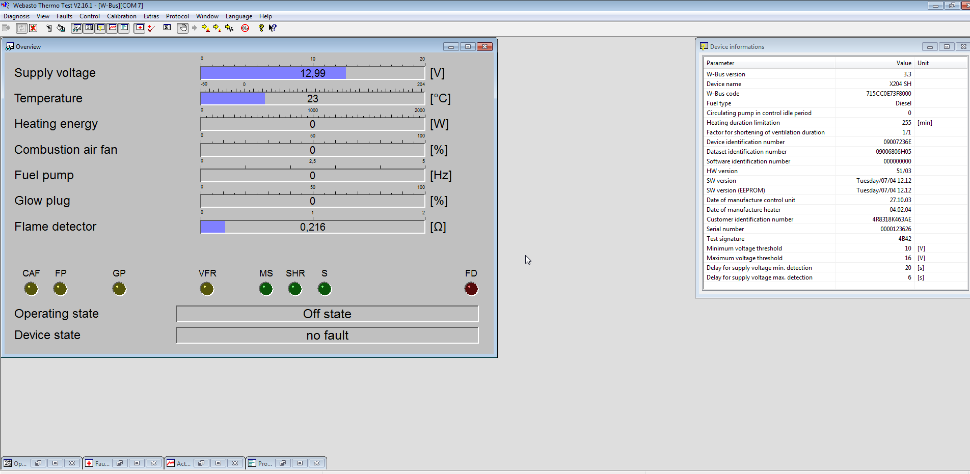
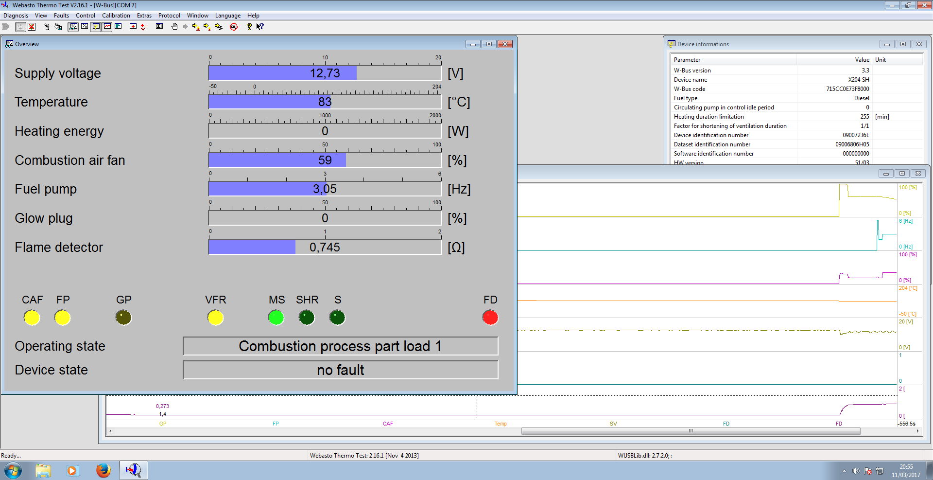
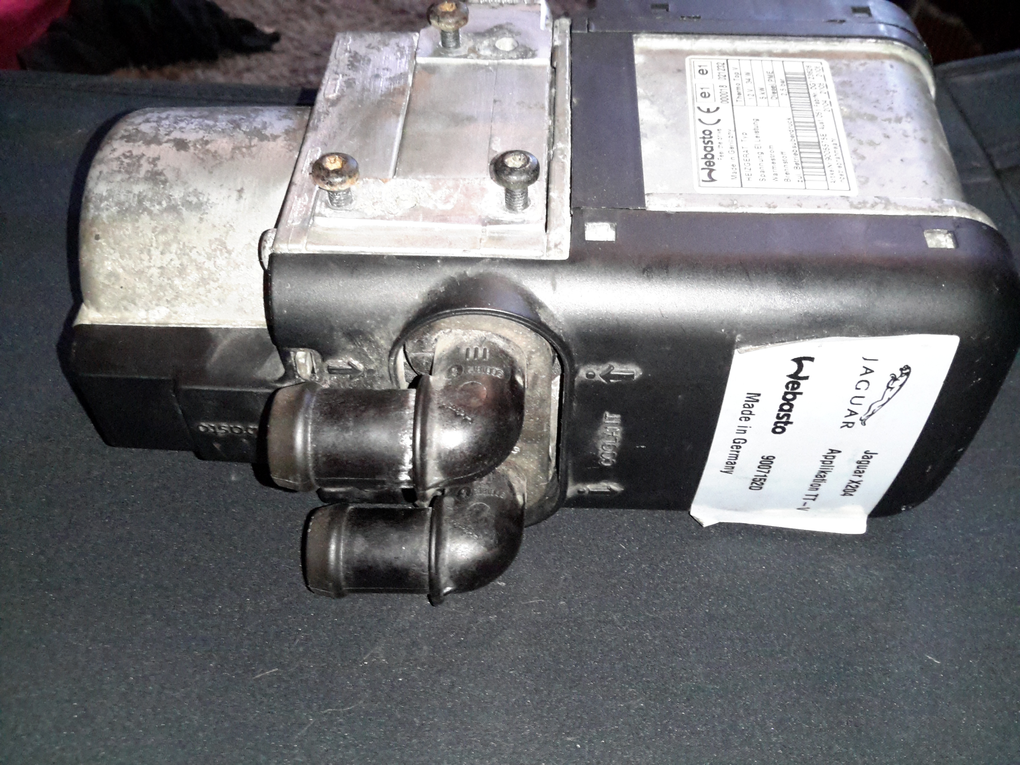
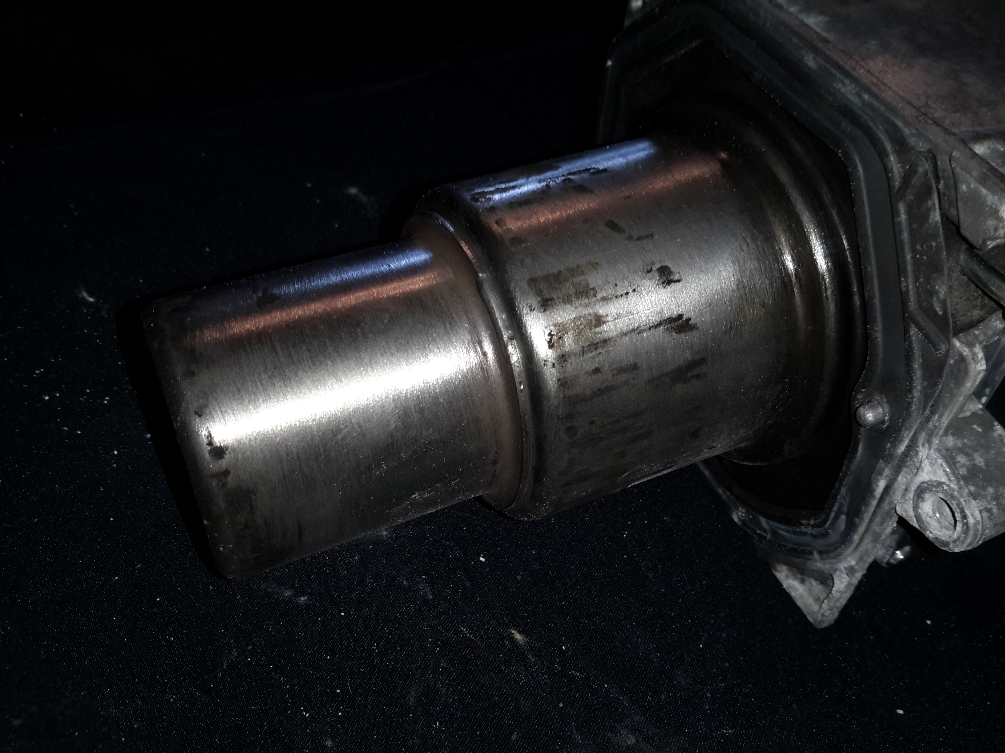
It recently became rather obvious there was something amiss with the water heater on board nb Tanya Louise – lots of smoke from the exhaust, failed starts, and finally a total refusal to start altogether.

Combustion Chamber
Combustion Chamber

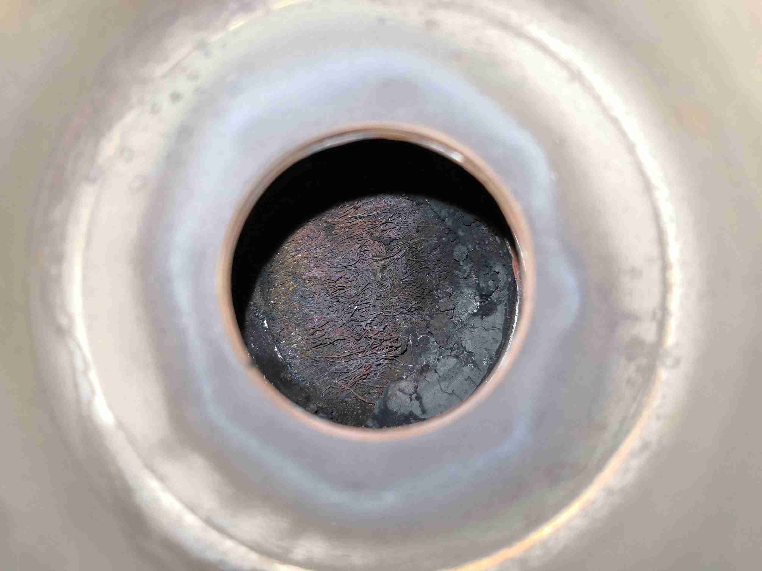
On disassembly, it was clear the burner was the issue – above. The mesh at the back where the fuel inlet enters the burner is completely knackered. The burner in these heaters, like the Eberspachers, is evaporative. Diesel fuel is led into a high-surface area mesh tube, or pad in this case, where it is vaporized to be burned with air from the combustion blower. Initially, this heat is provided by the glow plug, but after the unit has fired, the heat of combustion keeps the process going.

Burner Deposits 1
Burner Deposits 1

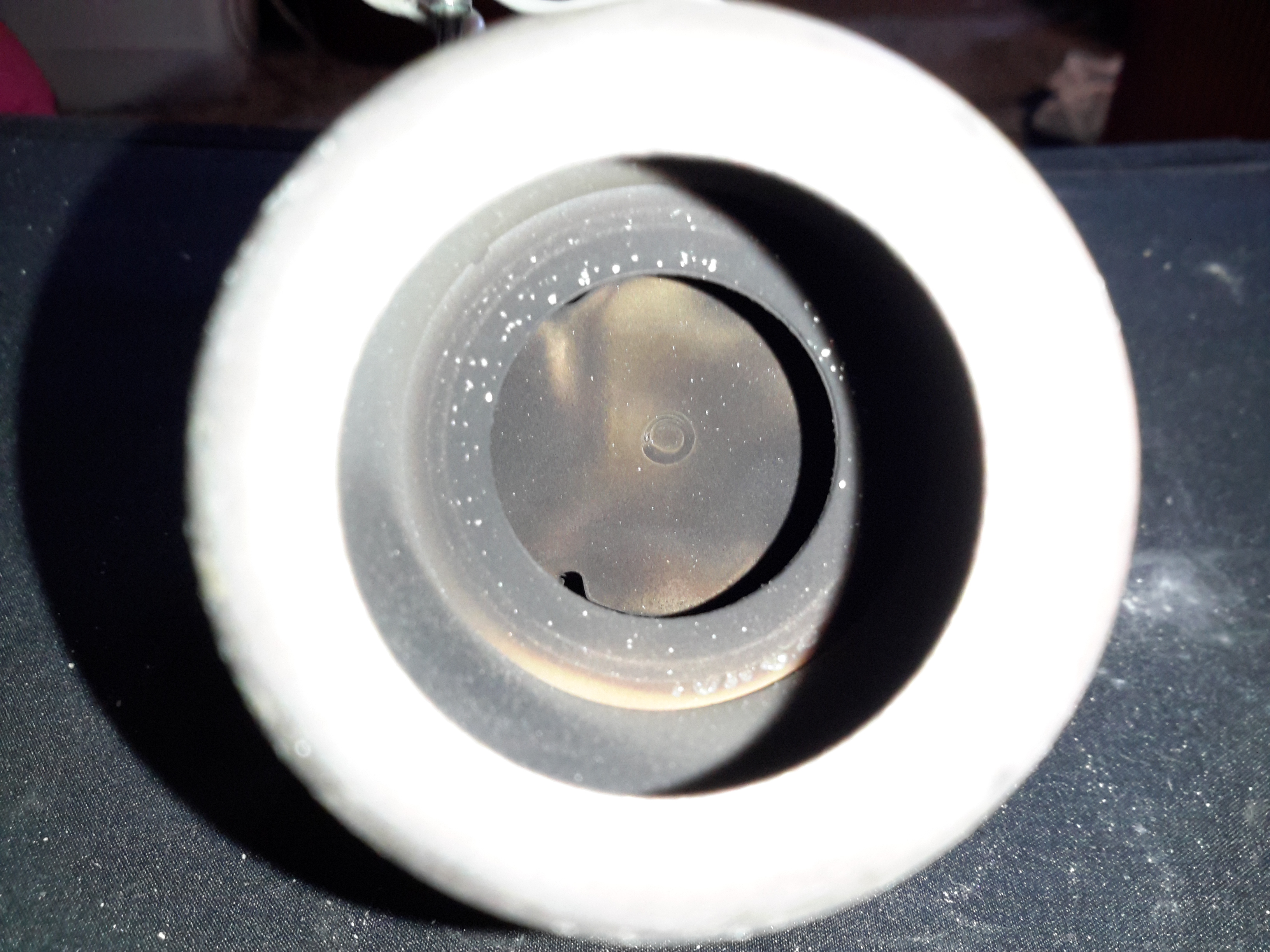
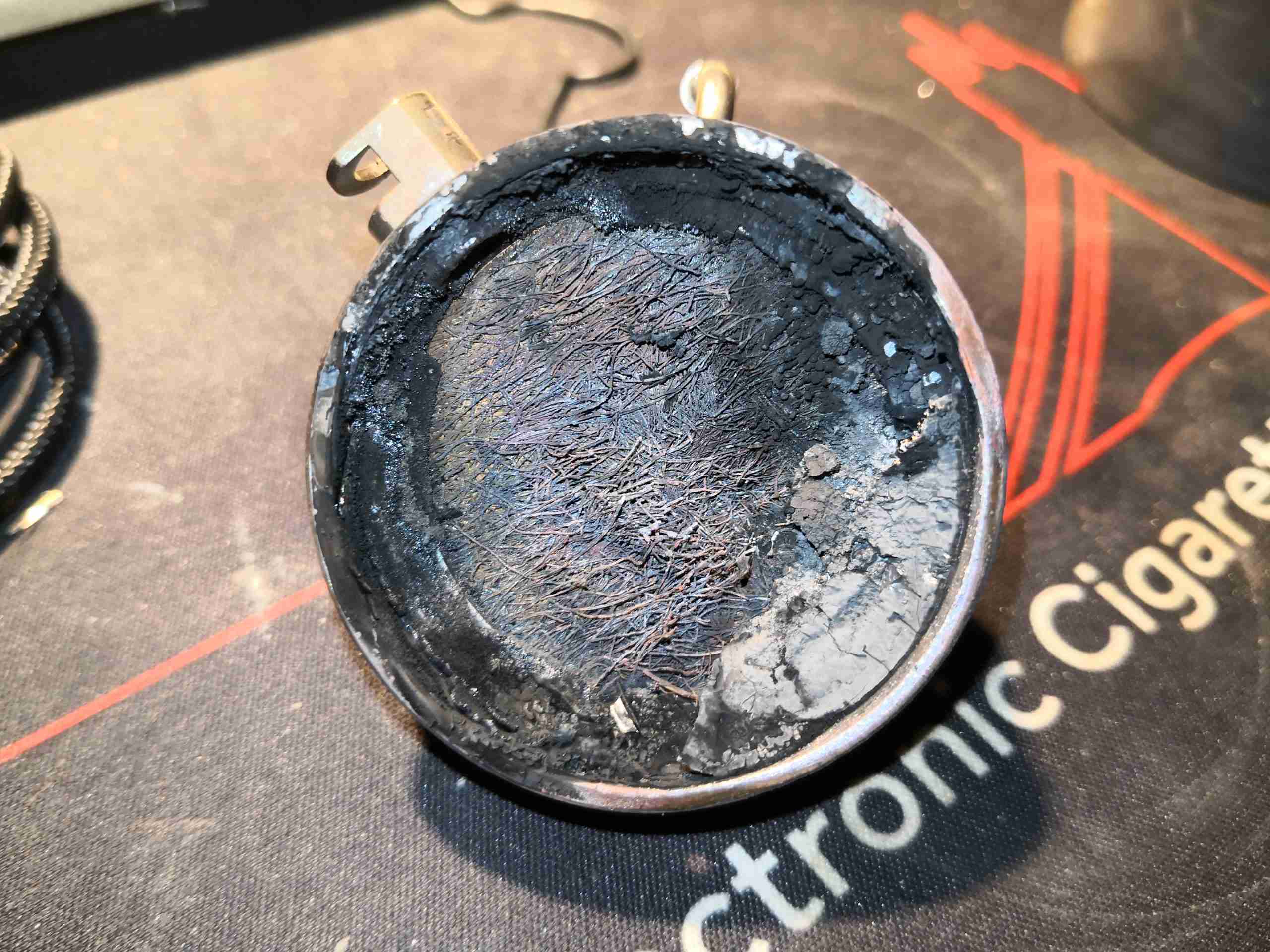
As can be seen at left, there’s quite the build-up of solid carbon around the burner, blocking most of the mesh & the air mixing holes in the tube. This was also after I’d removed most of the fouling!

Burner Deposits 2
Burner Deposits 2


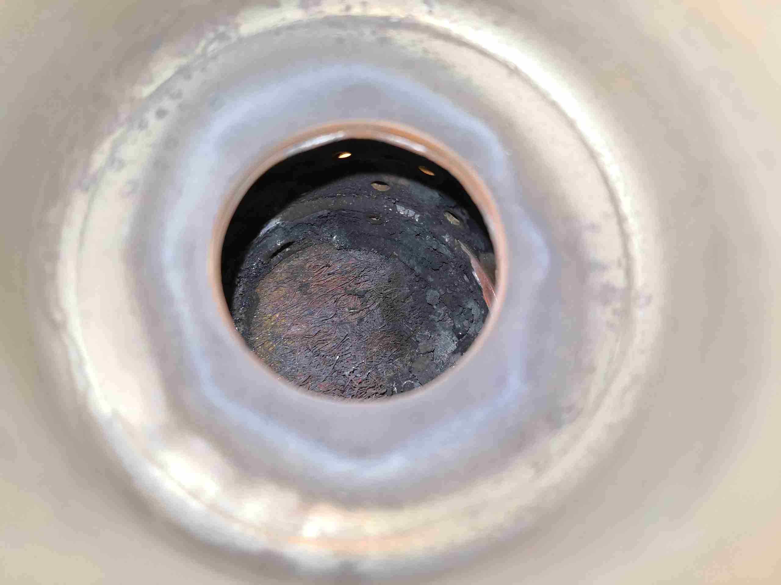
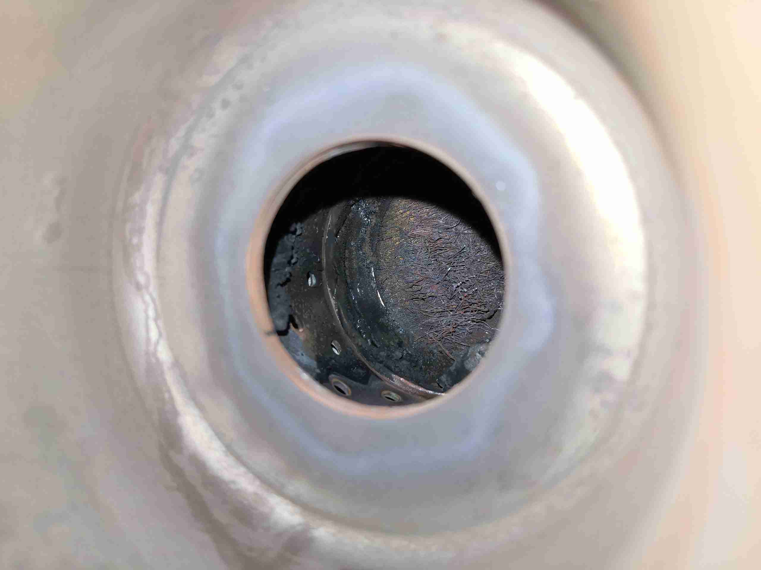
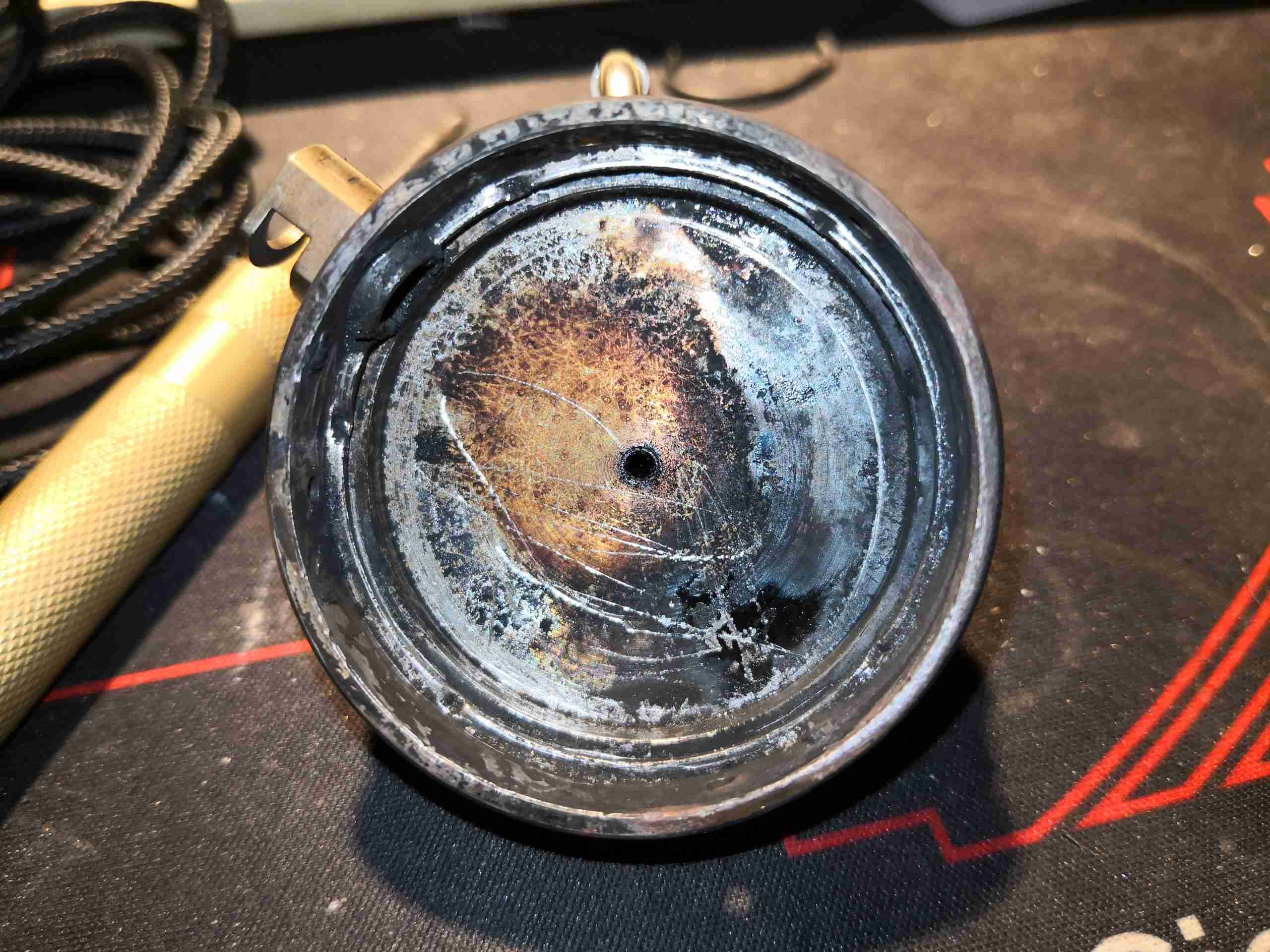
More deposits are seen on the other side, along with some of the air mixing holes.


Inlet Plate
Inlet Plate

Now, the problem is that these burner units are not meant to be refurbished. These units are considered by the manufacturer to be disposable, and are welded together as a result. There’s another issue – I don’t believe that a component costing around £295 in a service kit as DISPOSABLE. There’s nothing wrong with the structure of the burner at all – it’s Stainless Steel, and is in good shape with no heat damage. The only fault is with the mesh being burned out from long use. Luckily, replacement burner meshes are available on eBay from Chinese suppliers, so on with the repair!
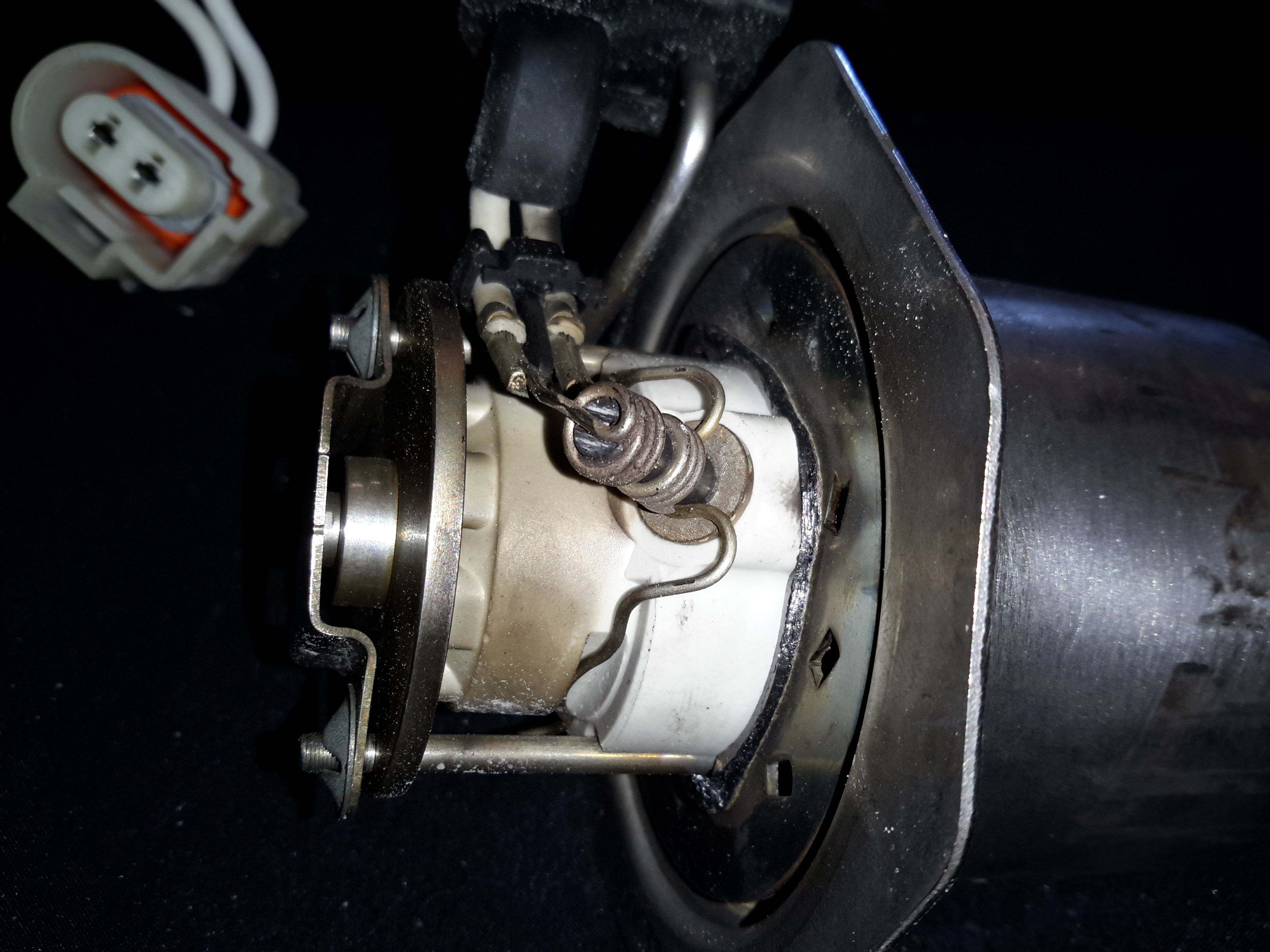
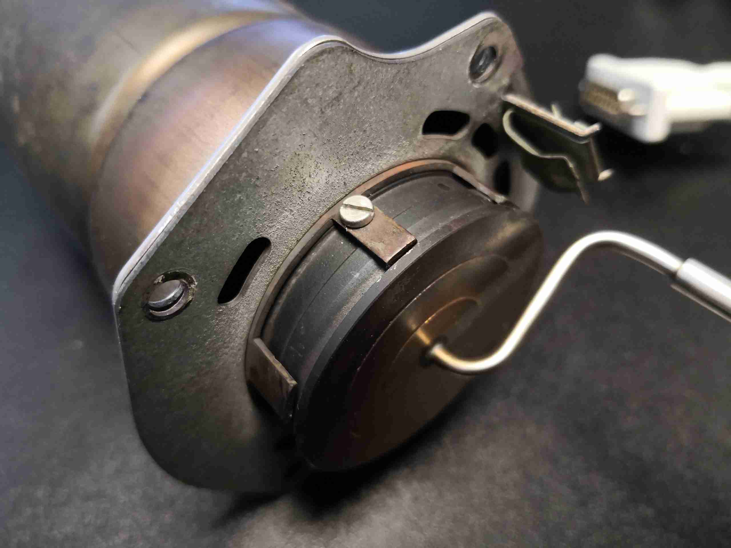
One of the welds that needs to be removed can be seen here next to the glow plug well, and there are 3 spots around the rim that are welded in this way. Delicate use of a grinding wheel on the welds allows this to be removed intact.

Burner Tube
Burner Tube

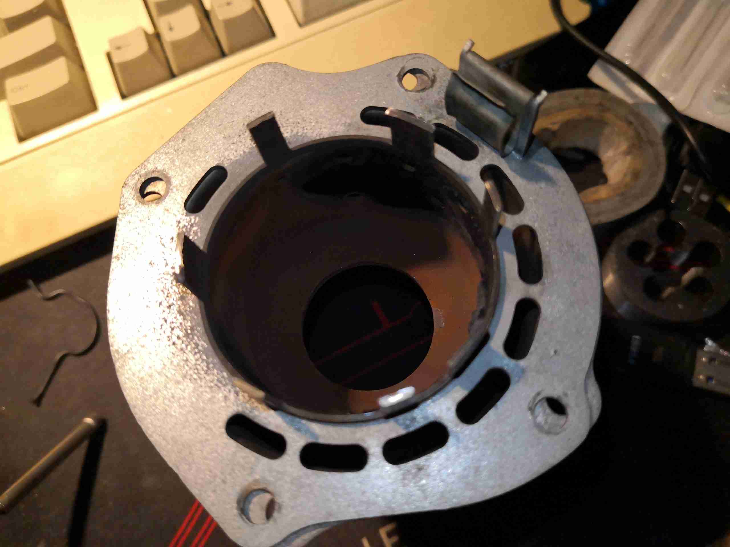
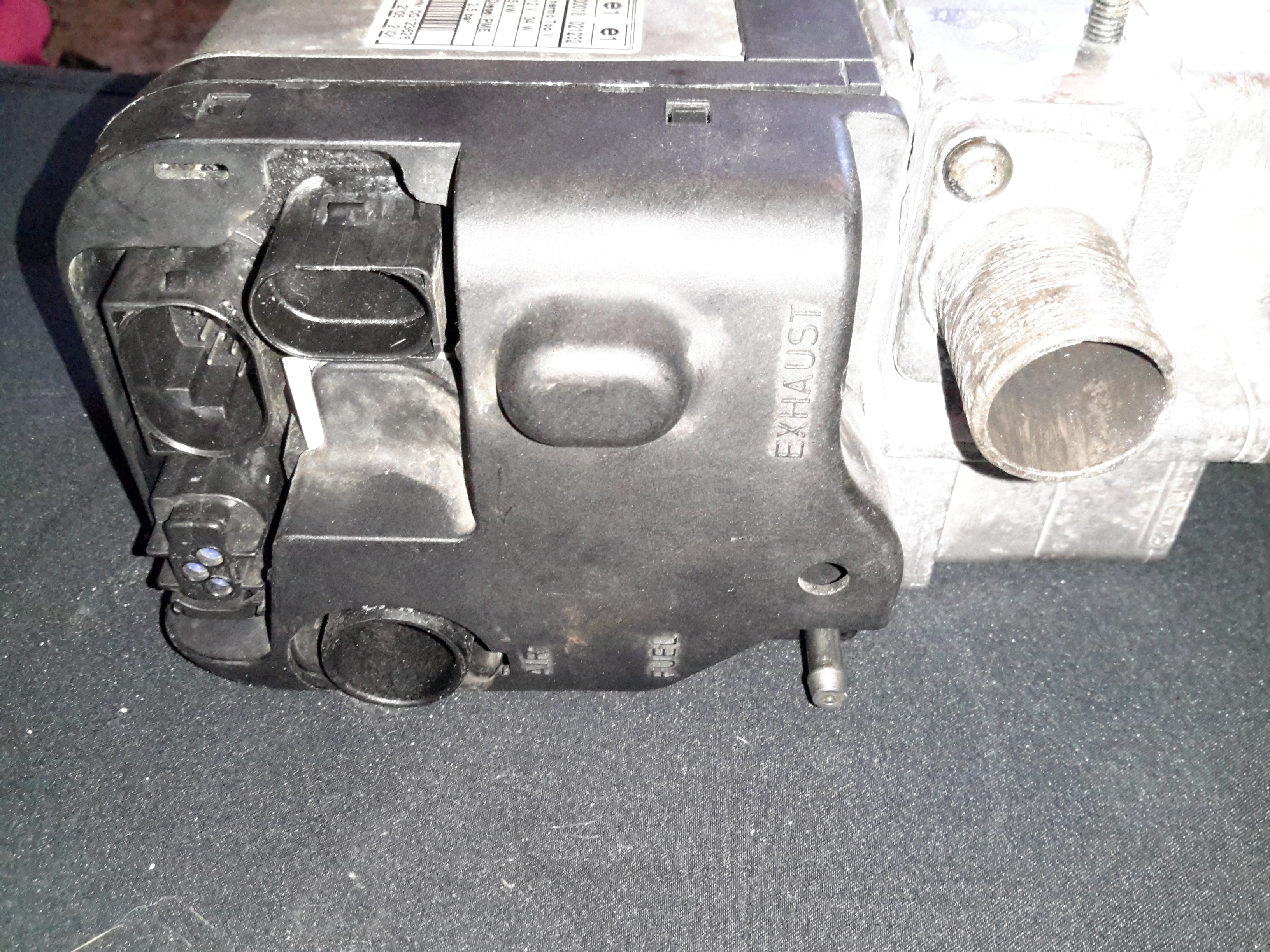
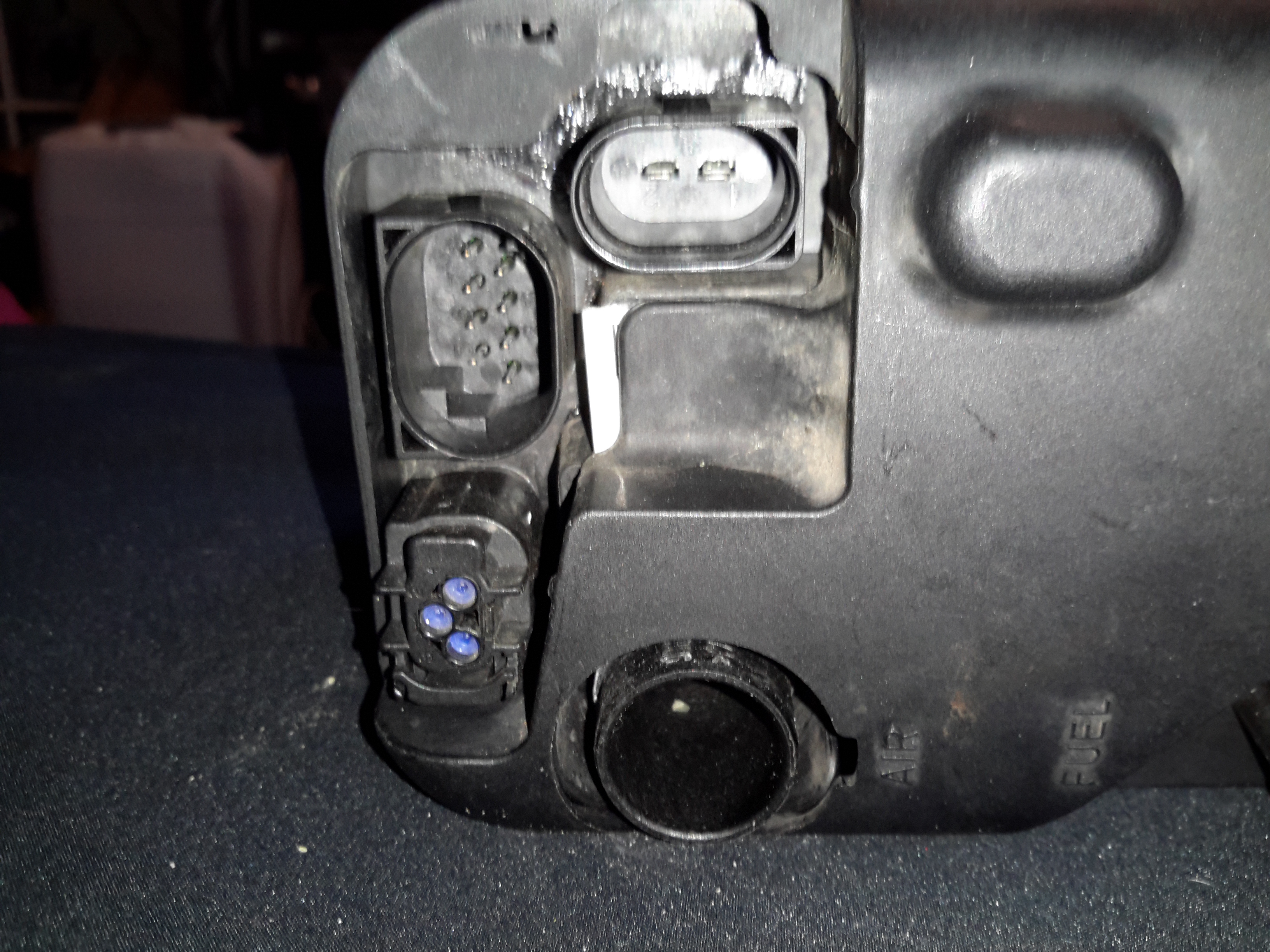
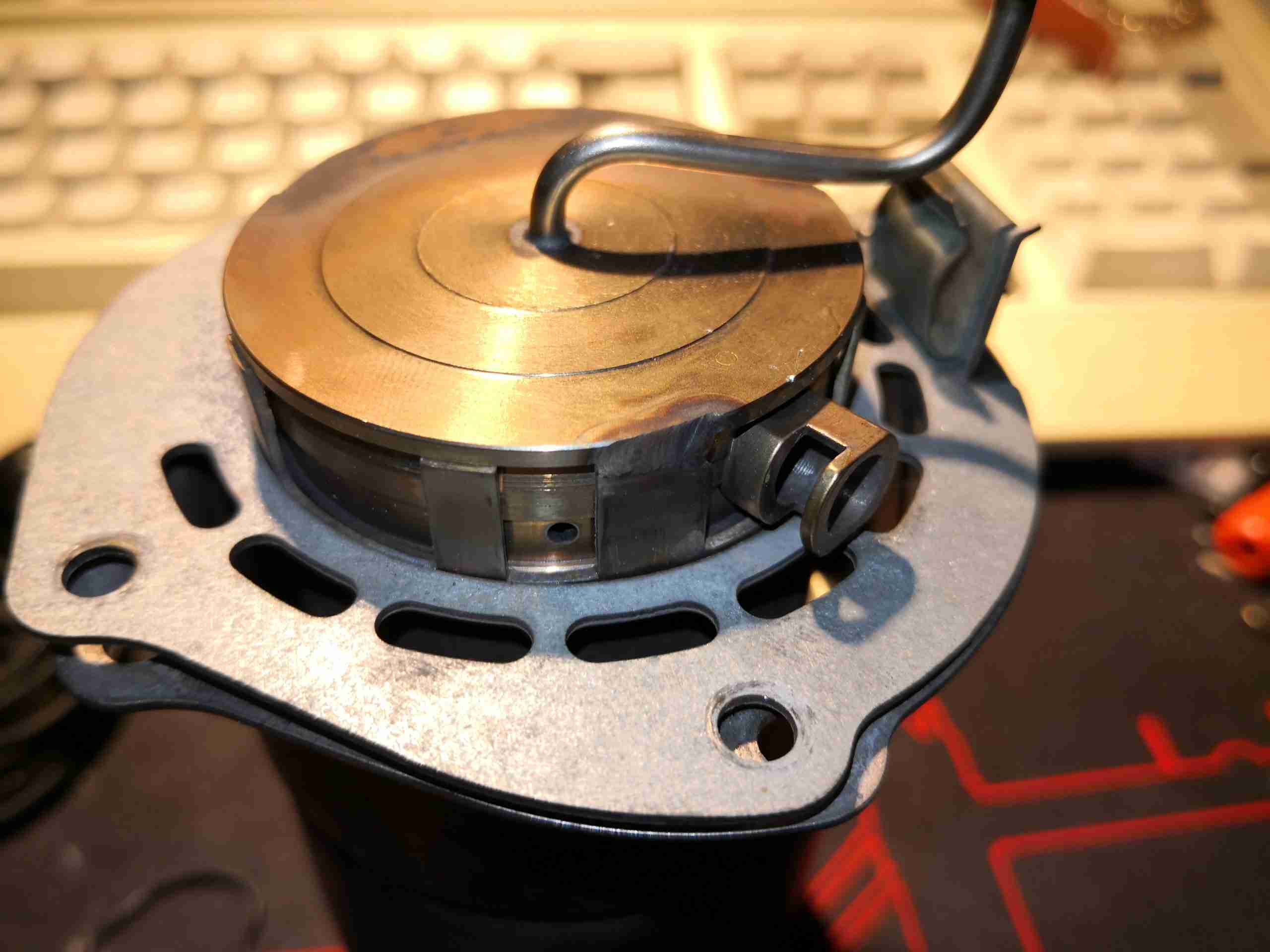
Once the welds have been ground off, the fuel inlet plate with the mesh can be pulled from the back of the burner. It’s a good idea to add some registration marks to both pieces before they’re separated, so they can be put back together in the same orientation – required for both the glow plug wiring, and the fuel inlet tube to line up with the hole in the heater housing. The ring of slots visible around the edge of the tube are the combustion air inlets, and the air is directed through a ring of holes in the combustion chamber, quite similar to a turbine engine combustor.

Old Burner Mesh
Old Burner Mesh

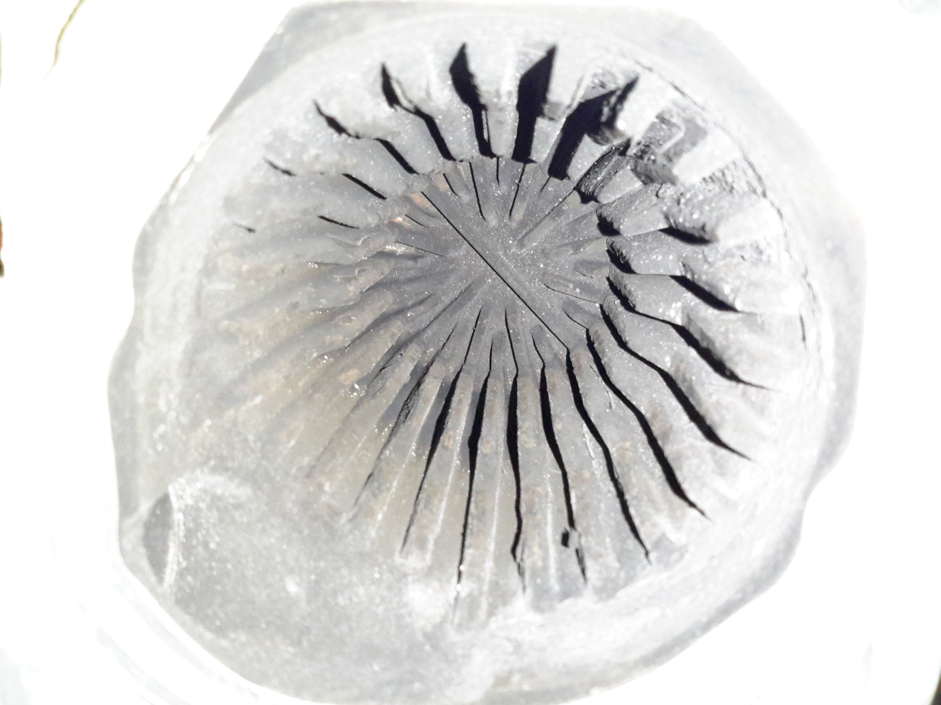
Now I’ve got the back of the burner removed, the clogging is much easier to see. The mesh itself has clearly been subject to very high heat, and is partially burned away, along with most of the surface being clogged up with coal from incomplete combustion. It’s difficult to see here, but the mesh pad is held in place with a large circlip around the edge, all will become clear after cleaning. All the hard carbon needs to be scraped out of the cup, clearing the way for the clip to be pried out of it’s groove.

Cleaned Cup
Cleaned Cup

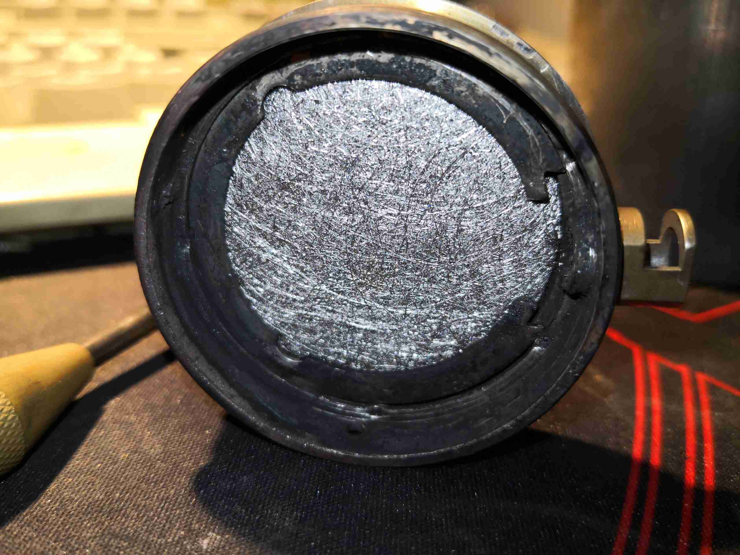
After a lot of scraping with the sharp end of a small screwdriver, the cup has been relieved of enough carbon to be recognisable again! The fuel inlet tube is in the centre of the backplate, with the circlip groove around the edge. Crimp marks are visible on the top edge of the groove – I think Webasto actually crimps the ring in place after fitting, which does make removal a bit more tricky, but I did manage to get it out intact, even if heat has removed most of the heat treat from the steel – making it soft. Be careful here!

New Mesh Fitted
New Mesh Fitted

Fitting the new mesh is pretty simple. These have a sharp pressed side & a convex side, the convex side must face outwards from the cup. The circlip is visible around the edge of the mesh, with the ends next to the glow plug well. Make sure that the clip is equally spaced around the glow plug  to make sure it doesn’t foul the plug when that’s replaced.

Now comes the issue of reattaching the cup to the back of the burner tube. I didn’t want to re-weld, since the assembly is Stainless Steel & I don’t have a TIG setup at present. I do have some stainless wire for the MIG, but this would also leave me with the issue of future disassembly if the mesh needs replacement again. Brazing is also not possible for the same reason – once brazed, it’s a permanent assembly.

Burner Reassembled
Burner Reassembled

Since there are some tabs that were never welded, I decided to drill & tap M2.5 through these & use 304 stainless screws to hold the components together. This should allow removal in the future if required.

Posted on 11 Comments

Jaguar S-Type Aux Heater / Webasto Thermo Top V Part 2 – W-Bus Diagnostics

As I mentioned in the previous post, these heaters have a standard interface that’s used for control & diagnostics, the W-Bus. This is transmitted over the K-Line of the vehicle bus, and all heaters, regardless of firmware modifications done by the various car manufacturers respond to this interface. Official Webasto diagnostic adaptors are available, but these are just a very expensive serial adaptor. A much cheaper option is a ~£5 Universal ODB adaptor.

ODB2
ODB2

Above shows the signals on the ODB connector – the ones we’re interested in here are Pin 16, the +12v supply, and Pin 7, K-Line. Connect Pin 16 to the positive supply to the heater, and Pin 7 to Pin 2 on the Webasto heater. (Valid for all TT-V heaters).

Device Selection
Device Selection

Once these two connections are made to the heater, fire up the Thermo Test software. The screen above will be displayed. Pick W-Bus at top left.

COM Port Selection
COM Port Selection

First thing, connect the ODB adaptor to USB, and change to the correct COM port in Thermo Test. There may be several in the list, but a newly connected USB device should show up with the highest COM number.

Thermo Test
Thermo Test

Once Thermo Test is running, start communications by going to the Diagnosis Menu > Start Diagnostic (F2 keyboard shortcut).

Initialized
Initialized

After a few seconds, communication will be established. This will show faults, if any are present, and allow testing of the heater & it’s component parts. A summary report can be generated with Diagnosis > View Summary:

This shows all the important stuff, including running hours. (5388Hrs on this heater!). Most importantly, there are no faults listed.

Heater Running
Heater Running

The heater can be fully tested by issuing a start command from the Command Menu > Parking Heating option. Obviously cooling water will be required for this, along with an external water pump. (The water pump control output on these heaters seems to be totally disabled in firmware, as they rely on the engine’s coolant pump). I used a bucket of water along with a small centrifugal pump to provide the cooling. During this test I noted that the firmware is much more aggressive in these units. The marine versions shut down at ~72°C water temperature, whereas these don’t so the same until ~90°C.

Now I’ve managed to communicate with the heater, I’ll get onto building a standalone controller so I can dispense with the Windows VM for control.

Posted on 5 Comments

Jaguar S-Type Aux Heater / Webasto Thermo Top V Part 1 – Teardown & Cleaning

Jag Label
Jag Label

Here’s another Diesel-fired heater related project – these Webasto heaters are fitted to Jaguar S-Type cars as auxiliary heaters, since (according to the Jag manual), the modern fuel-efficient diesels produce so little waste heat that extra help is required to run the car’s climate control system. (Although this seems to nullify any fuel efficiency boost, as the fuel saved by not producing so much waste heat in the engine itself is burned in an aux heater to provide heat anyway). The unfortunate part is these units don’t respond to applying +12v to Pin 1 of the ECU to get them to start – they are programmed to respond to CAN Bus & K-Line Bus only, so they require a bit more effort to get going. They also don’t have a built-in water circulation pump unlike the Webasto Thermo Top C heaters – they expect the water flow to be taken care of by the engine’s coolant pump.

Webasto Label
Webasto Label
Water Side
Water Side

The water ports are on the side of this heater instead of the end, the heat exhanger is on the left. These hearers are fitted to the car under the left front wing, behind a splash guard. Pretty easy to get to but they get exposed to all the road dirt, water & salt so corrosion is a little problem. The fuel dosing pump is in a much more difficult spot to get at – it’s under the car next to the fuel tank on the right hand side. Access to the underside with stands is required to get at this.

ECU Side
ECU Side

The ECU side has all the other connections – Combustion air, exhaust, fuel, power & control.

External Connectors
External Connectors

Only two of the external connectors are used on these heaters, the large two pin one is for main power – heavy cable required here as the current draw can climb to ~30A on startup while the glow plug fires. The 8-pin connector on the left is the control connector, where the CAN / K-Line / W-Bus buses live. The fuel dosing pump is also supplied from a pin on this connector. The small 3-pin under that is a blank for a circulation pump where fitted. Pinouts are here:

PinSignal
1Battery Positive
2Battery Negative
Pin NumberSignalNotes
1Telestart / Heater EnableWould usually start the heater with a simple +12v ON signal, but is disabled in these heaters.
2W-Bus / K-LineDiagnostic Serial Bus Or Webasto Type 1533 Programmer / Clock
3External Temp Sensor
4CAN-CAN Bus Low
5Fuel Dosing PumpFuel Pump output. Connect pump to this pin & ground. Polarity unimportant.
6Solenoid ValveFuel cutoff solenoid optionally fitted here.
7CAN+CAN Bus High
8Cabin Heater Fan ControlThis output switches on when heater reaches +50°C to control car heater blower
PinSignalNotes
1??
2Circulation Pump +
3Circulation Pump -
ECU Cover Removed
ECU Cover Removed

Removing the clipped-on plastic cover reveals the other ECU connectors. The large white one feeds the glow plug, & the large multi-pin below brings in the temp & overheat sensor signals.

MC9S12DT128B Microcontroller

The heart of the ECU is a massive microcontroller, a Freescale MC9S12DT128B, attached to a daughterboard hooked into the ECU power board.

Power Section
Power Section

The high power section is on the board just under the connectors, here all the large semiconductors live for switching the fan motor, glow plug, external loads, etc.

LIN & CAN Bus Transceivers

The bus transceivers are separate ICs on the control board, a TJA1041 takes care of the CAN bus. There’s also a TJA1020 LIN bus transceiver here, which is confusing since none of the Webasto documentation mentions LIN bus control.

Combustion Fan Motor

The combustion fan motor is in the ECU compartment, nicely sealed away from the elements. There is no speed sensor on these blowers, unlike the Eberspacher ones.

Motor Details
Motor Details

The motor is a Buhler, rated at 10.5v.

Water Ports & Combustion Fan Cover

Unclipping the cover from the other end reveals the combustion fan, it’s under the black cover. (These are side-channel blowers, to provide the relatively high static pressure required to run the burner).

Sensor Clip
Sensor Clip

The overheat & temperature sensors are on the end of the heat exchanger, retained by a stainless clip.

Temp & Overheat Sensors

With the clip removed, the sensors can be seen better. There’s some pretty bad corrosion of the aluminium alloy on the end sensor, it’s seized in place.

Burner
Burner

The heater splits in half to reveal the evaporative burner itself. I’ve already cleaned the black crud off with a wire brush here, doesn’t look like this heater has seen much use as it’s pretty clean inside.

Burner Chamber
Burner Chamber

Inside the burner the fuel evaporates & is ignited. There is a brass mesh behind the backplate of the burner to assist with vaporisation.

Glow Plug
Glow Plug

The glow plug is fitted into the side of the burner ceramic here. This is probably a Silicon Carbide device. It also acts as a flame sensor when the heater has fired up. The fuel inlet line is to the left under the clamp.

Heat Exhanger
Heat Exhanger

The hot gases from the burner flow into the heat exchanger here, with many fins to increase the surface area. There’s only a couple of mm coating of carbon here, after 10 years on the car I would have expected it to be much more clogged.

I’m currently waiting on some components to build an interface so I can get the Webasto Thermo Test software to talk to the heater. Once this is done I can see if there are any faults logged that need sorting before I can get this heater running, but from the current state it seems to be pretty good visually. More to come once parts arrive!

The full service manual for these heaters can be grabbed from here, along with the wiring details for the Jaguar implementation & the Thermo Test software for talking to them:

[download id=”5618″]

[download id=”5620″]

[download id=”5622″]