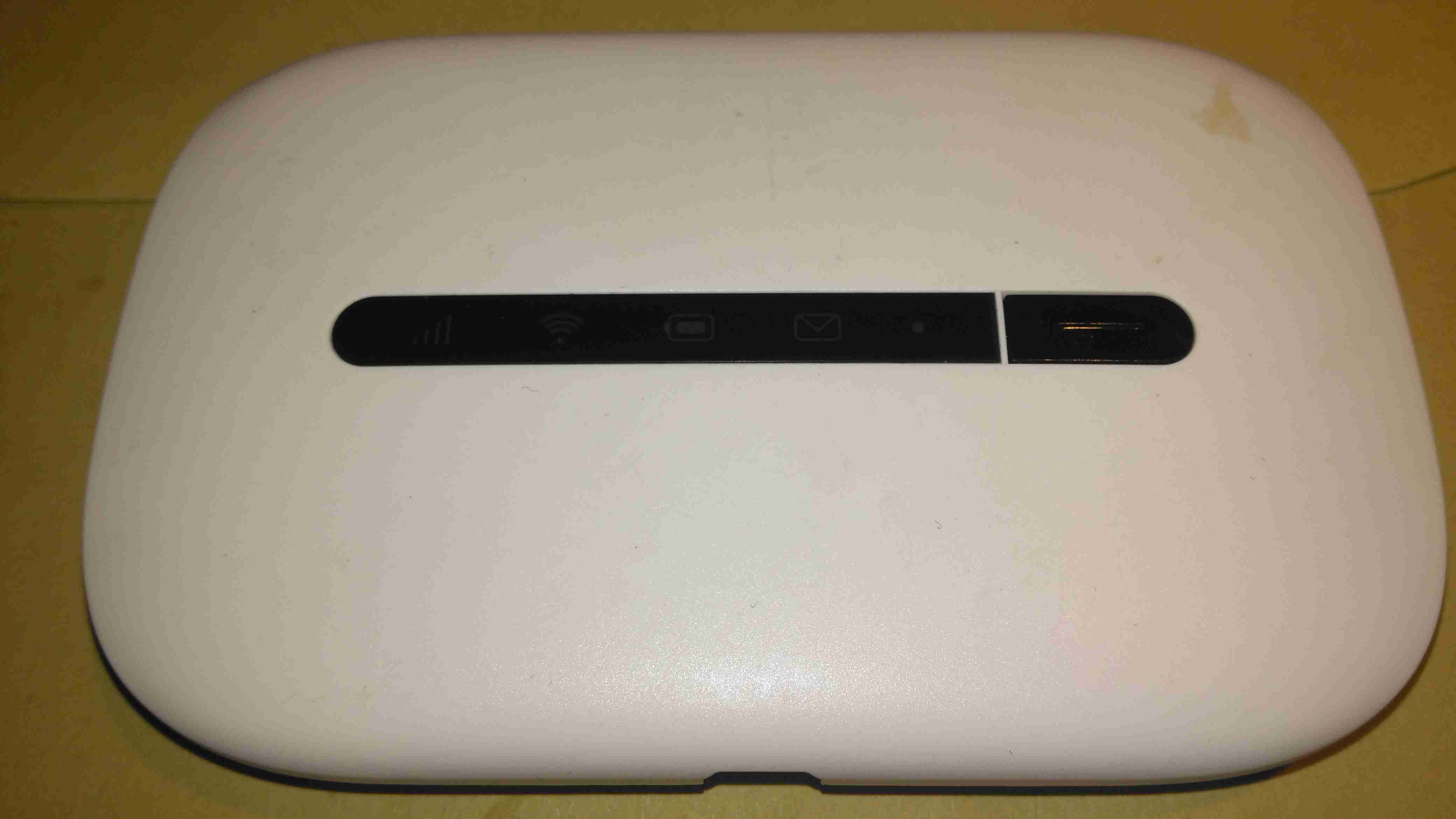
Here’s one of the old modems from my spares bin, a Vodafone Mobile WiFi R207. This is just a rebranded Huawei E5330. This unit includes a 3G modem, and a WiFi chipset, running firmware that makes this a mini-router, with NAT.
Specs
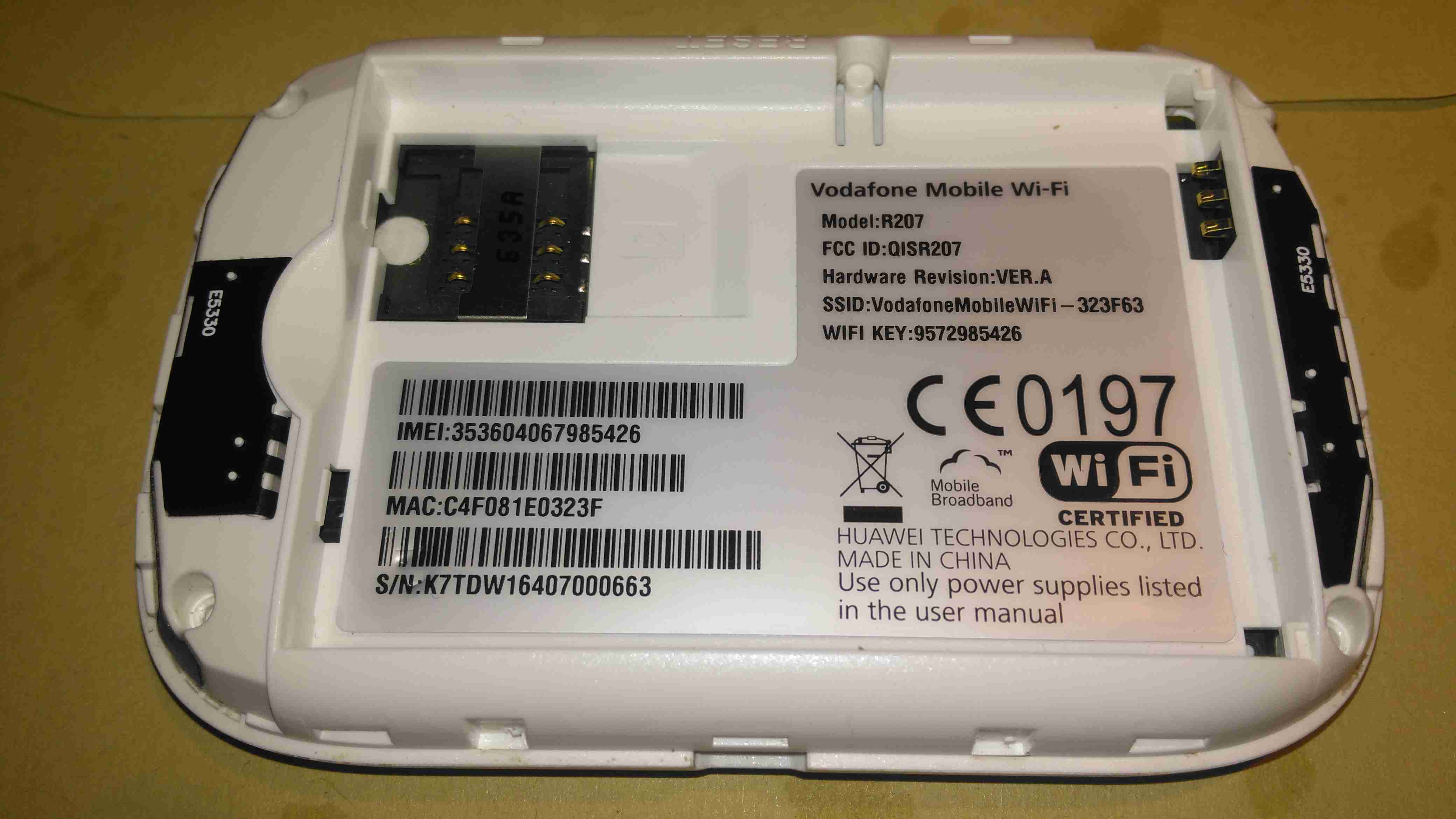
The back has the batter compartment & the SIM slot, with a large label showing all the important details.
Cover Removed
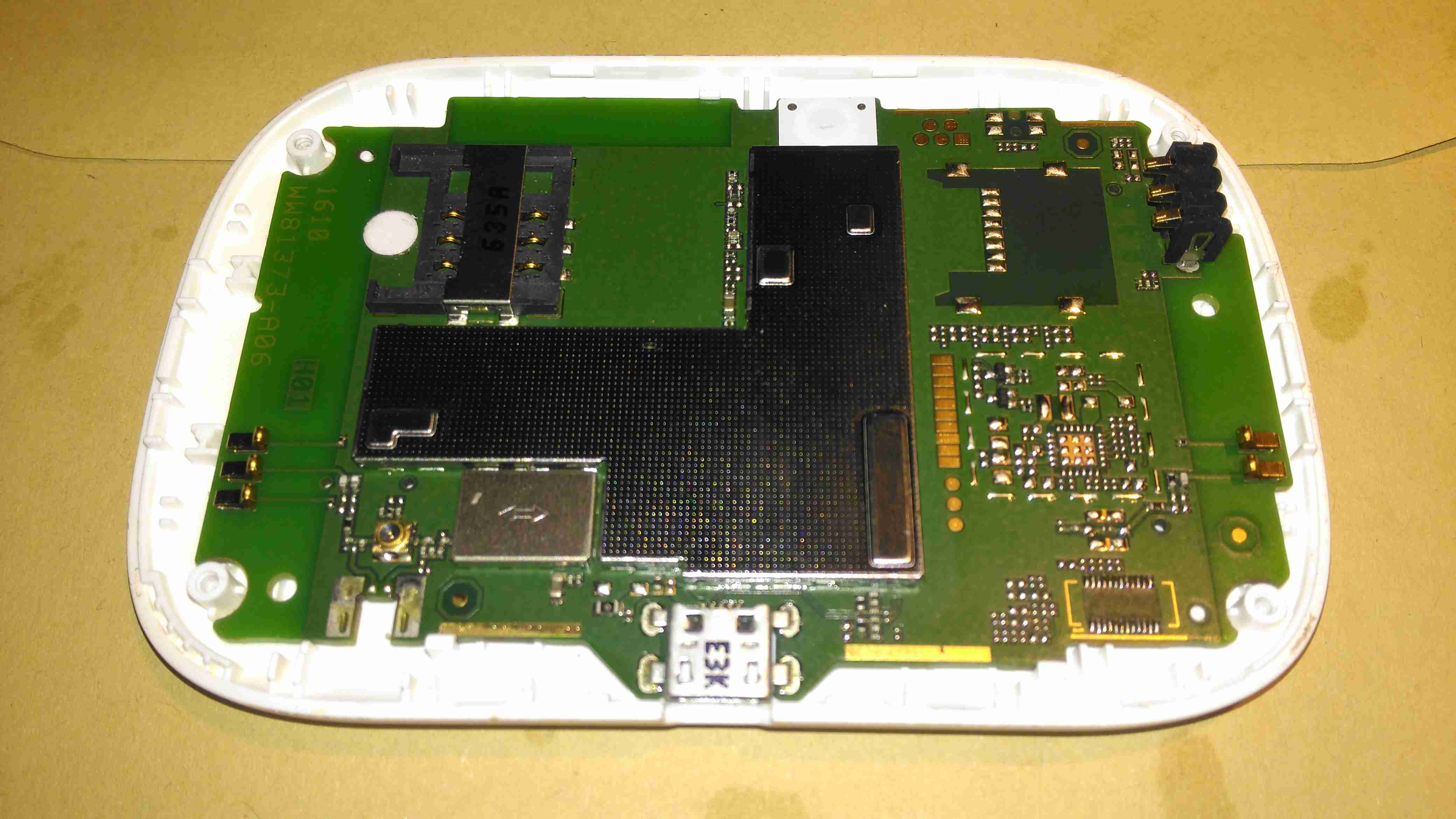
A couple of small Torx screws later & the shell splits in half. All the electronics are covered by shields here, but luckily they are the clip-on type, and aren’t soldered direct to the PCB.
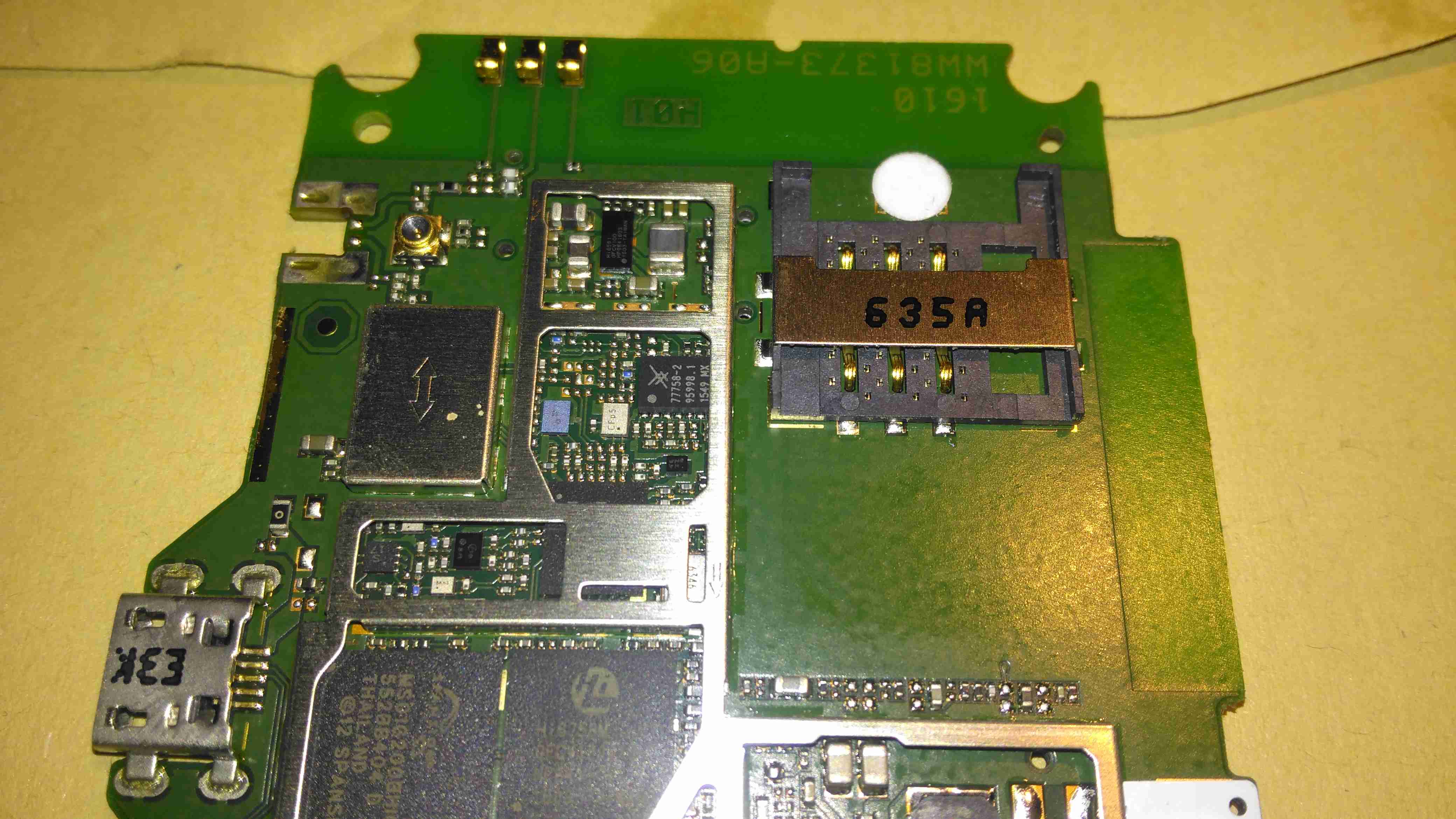
Chipset
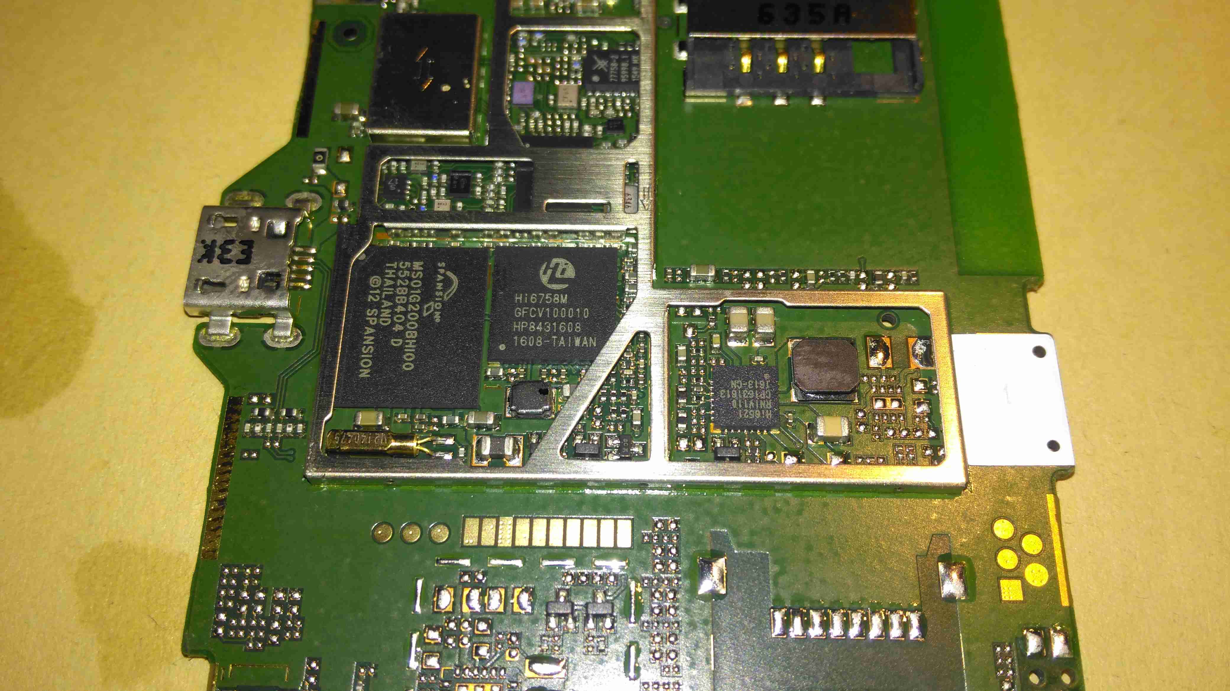
Once the shield has been removed, the main chipset is visible underneath. There’s a large Spansion MS01G200BHI00 1GBit flash, which is holding the firmware. Next to that is the Hi6758M baseband processor. This has all the hardware required to implement a 3G modem. Just to the right is a Hi6521 power management IC, which is dealing with all the power supplies needed by the CPU.
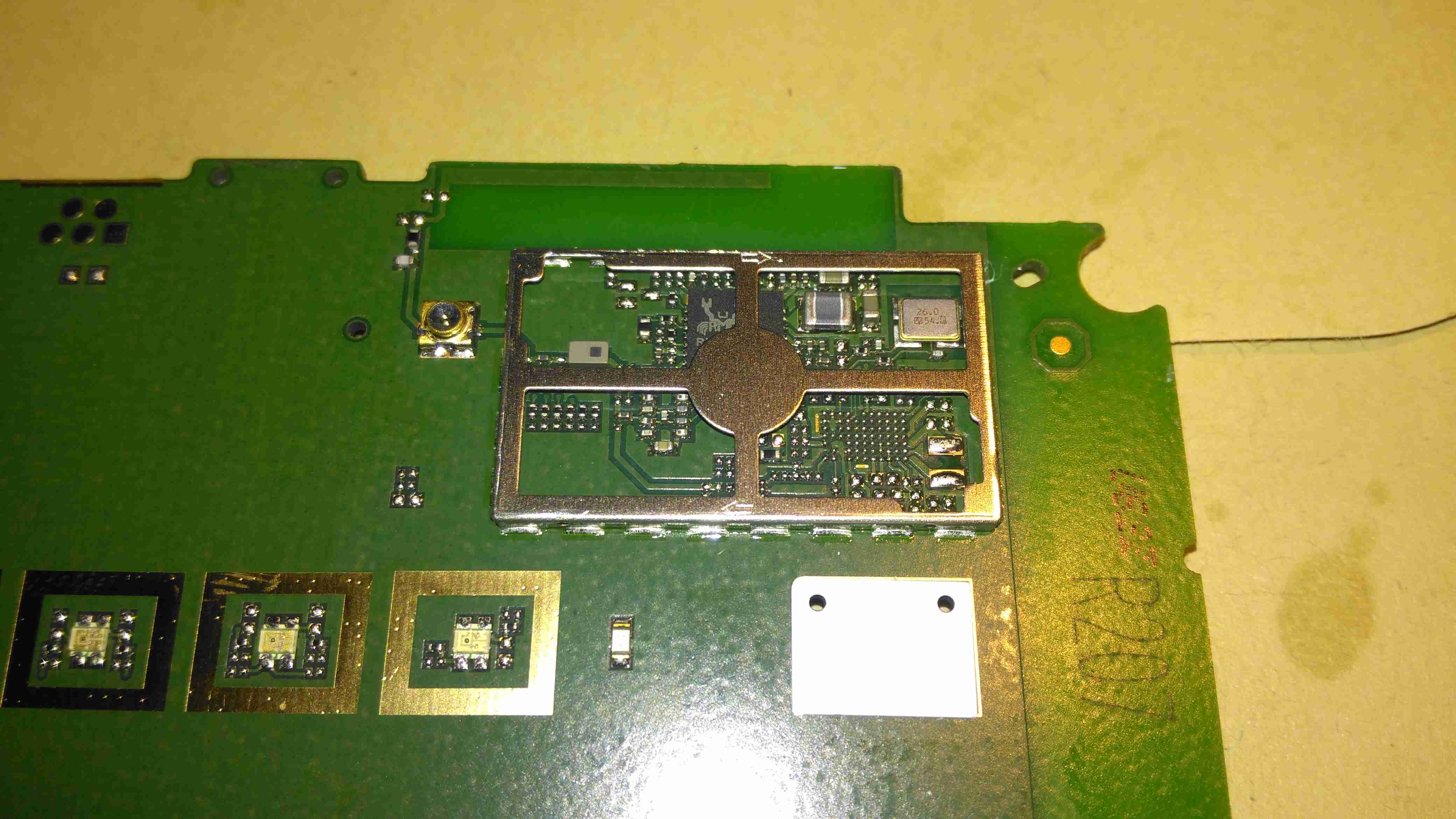
The RF section is above the baseband processor, some of which is hiding under the bits of the shield that aren’t removable.
SIM Socket
There’s a socket onboard for a standard Mini-SIM, just to the left of that is a Hi6561 4-phase buck converter. I would imagine this is providing the power supplies for the RF section & amplifier.
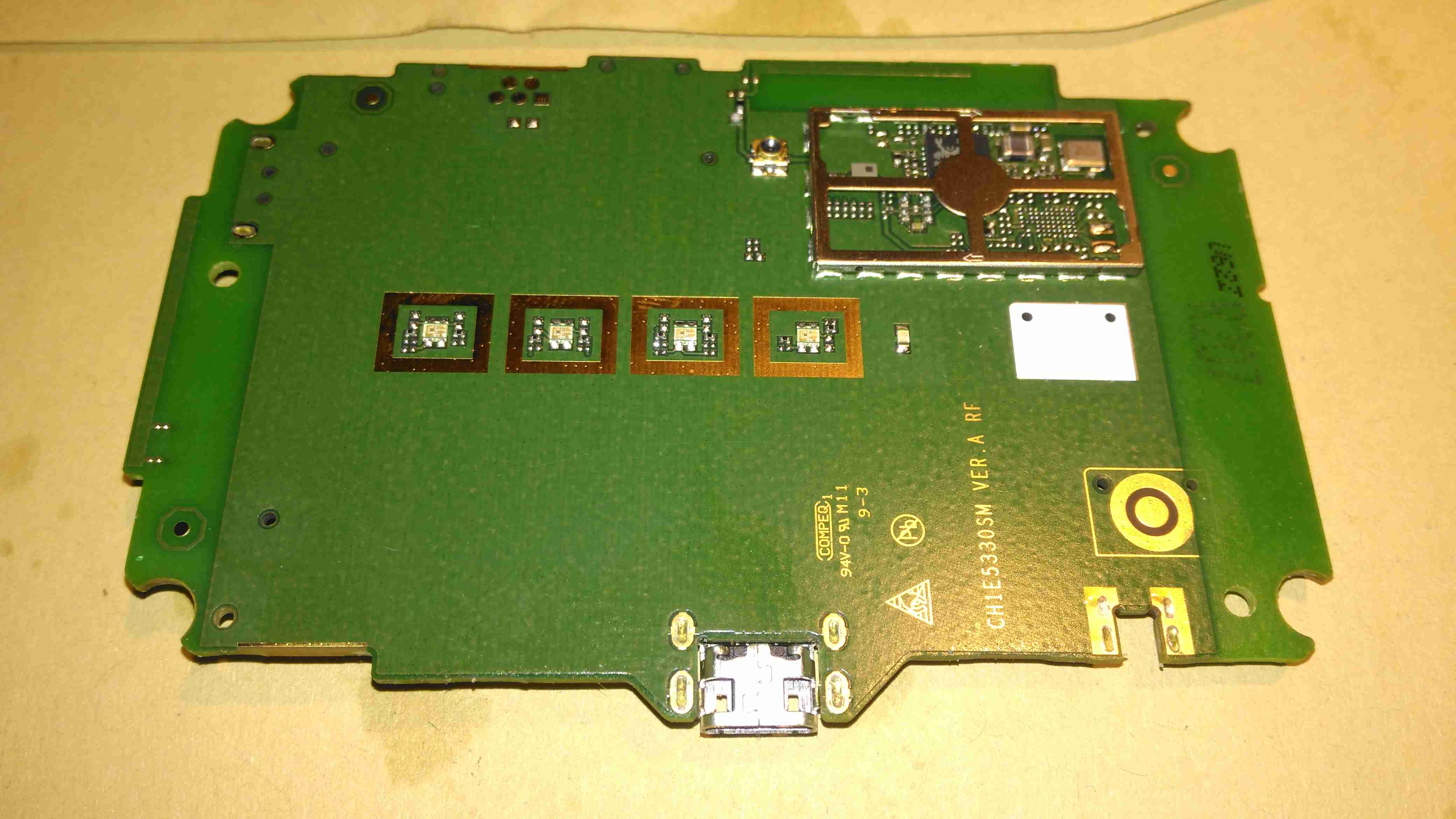
Unpopulated Parts
Not sure what this section is for, all the parts are unpopulated. Maybe a bluetooth option?
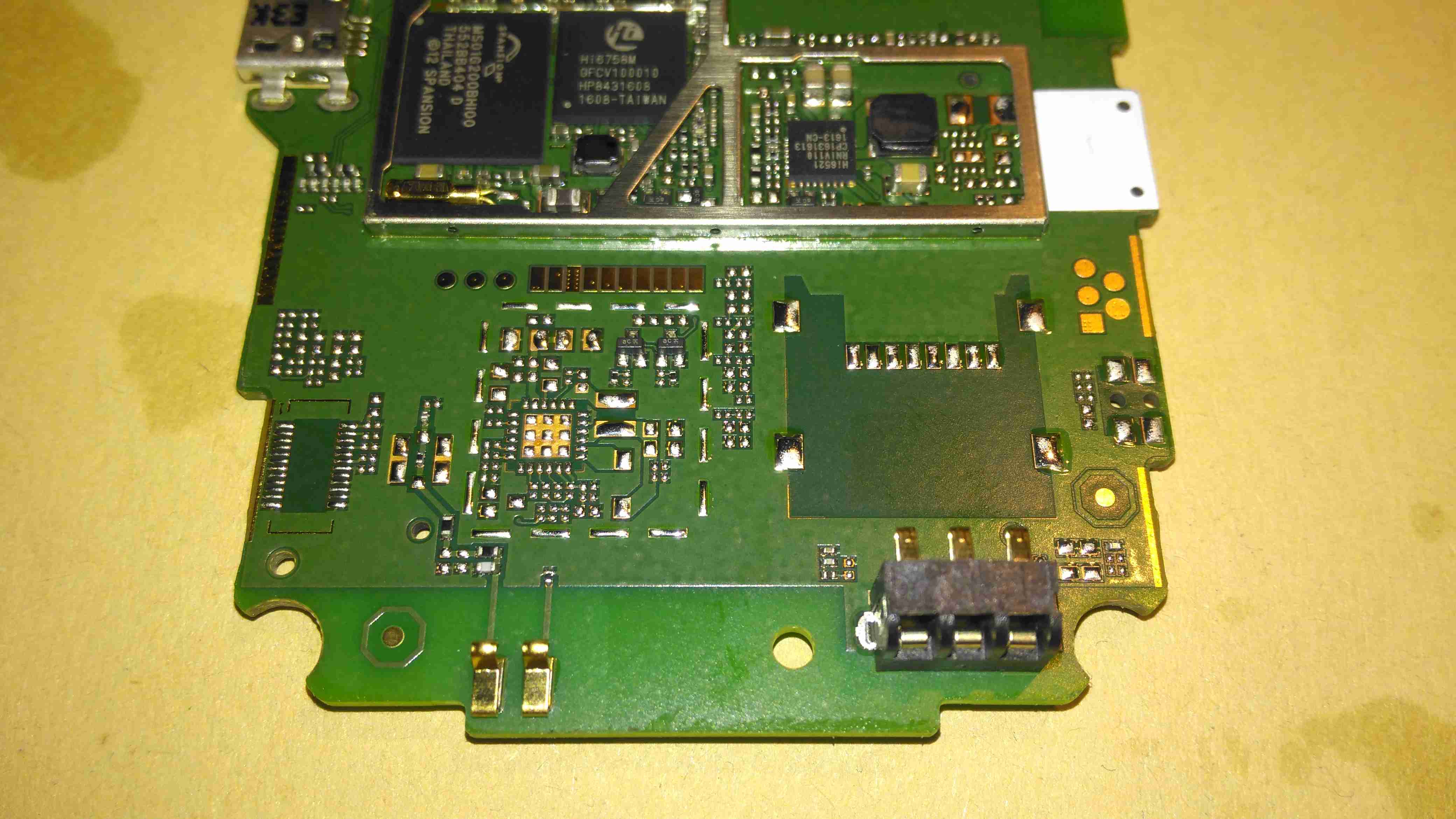
PCB Reverse
The other side of the PCB is pretty sparse, holding just the indicator LEDS, button & the WiFi Chipset.
Realtek WiFi Chipset
The chipset here is a Realtek part, but it’s number is hidden by some of the shield. The antenna connection is routed to the edge of the board, where a spring terminal on the plastic case mounted antenna makes contact.
Being in technology for a long time, I have seen my fair share of disk failures. However I have never seen a single instance where SMART has issued a sufficient warning to backup any data on a failing disk. The following is an example of this in action.
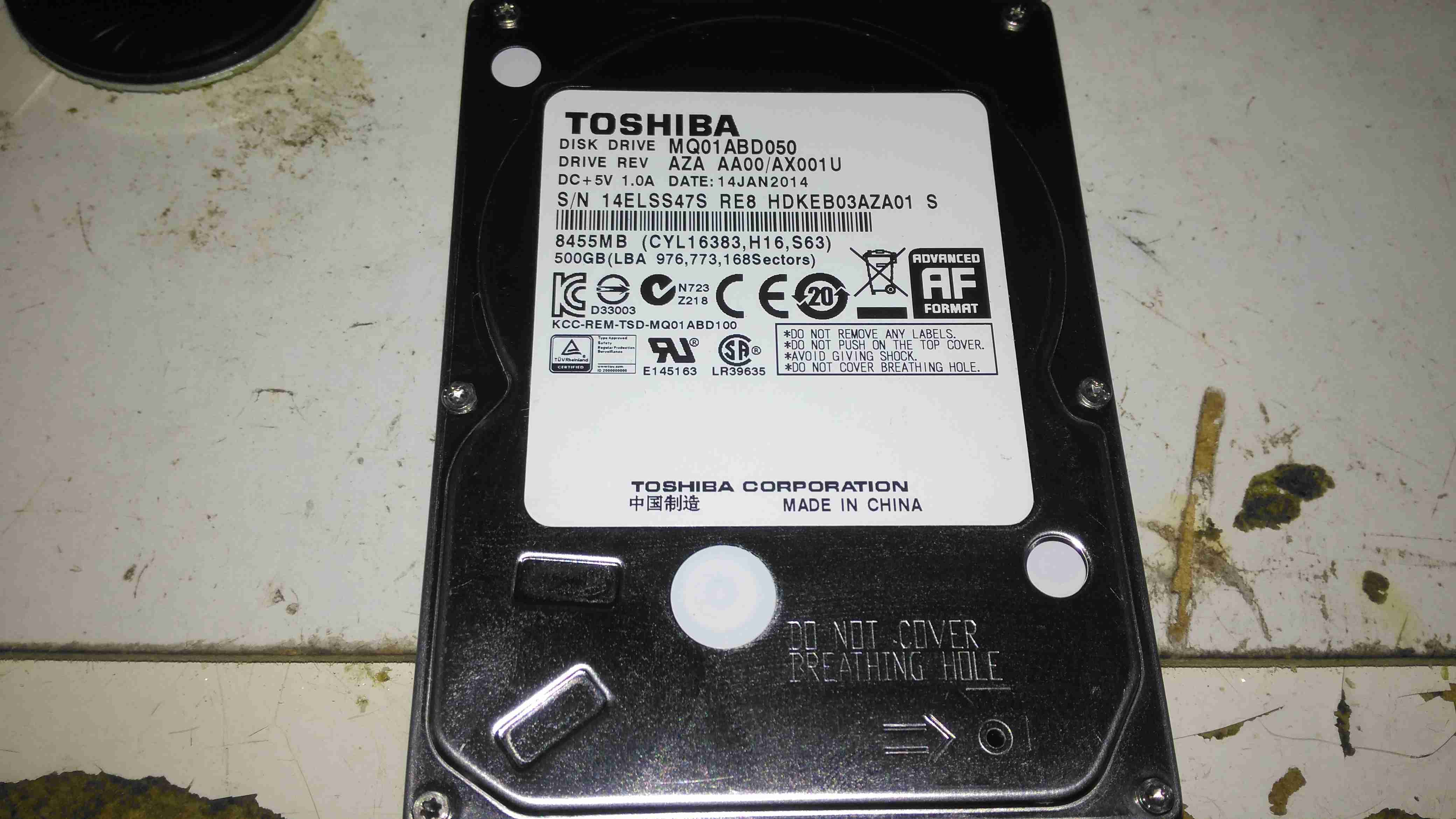
Toshiba MQ01ABD050
Here is a 2.5″ Toshiba MQ01ABD050 500GB disk drive. This unit was made in 2014, but has a very low hour count of ~8 months, with only ~5 months of the heads being loaded onto the platters, since it has been used to store offline files. This disk was working perfectly the last time it was plugged in a few weeks ago, but today within seconds of starting to transfer data, it began slowing down, then stopped entirely. A quick look at the SMART stats showed over 4000 reallocated sectors, so a full scan was initiated.
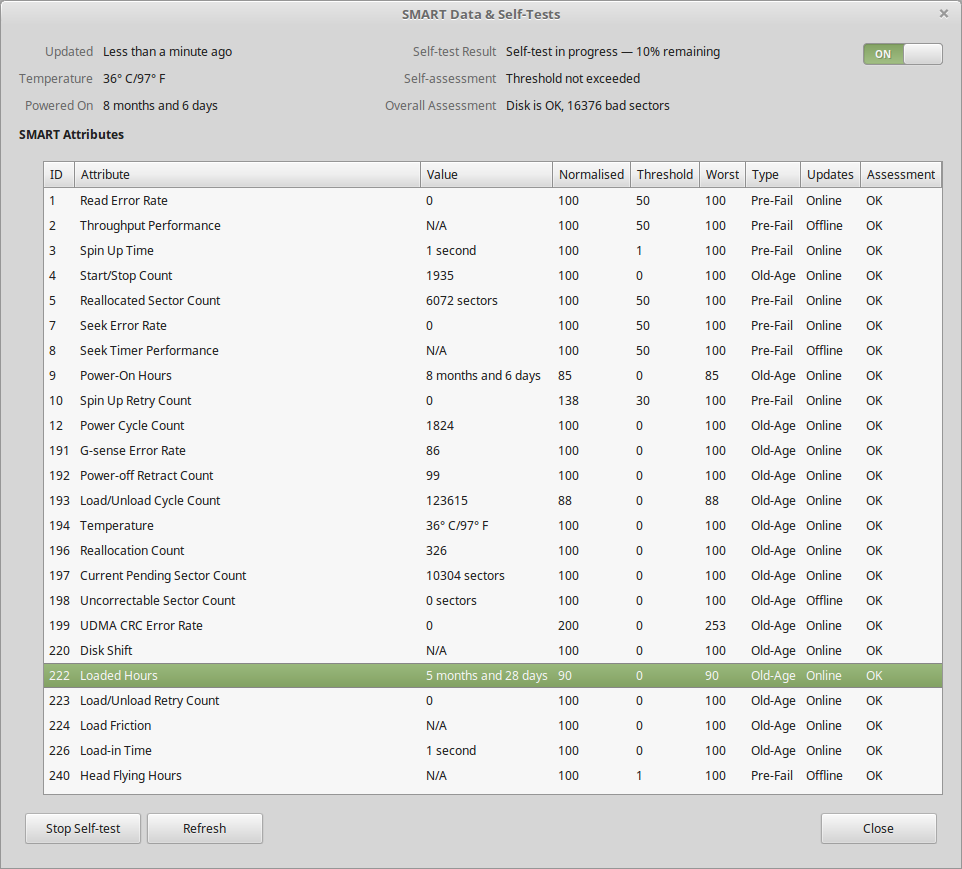
SMART Test Failure
After the couple of hours an extended test takes, the firmware managed to find a total of 16,376 bad sectors, of which 10K+ were still pending reallocation. Just after the test finished, the disk began making the usual clicking sound of the head actuator losing lock on the servo tracks. Yet SMART was still insisting that the disk was OK! In total about 3 hours between first power up & the disk failing entirely. This is possibly the most sudden failure of a disk I’ve seen so far, but SMART didn’t even twig from the huge number of sector reallocations that something was amiss. I don’t believe the platters are at fault here, it’s most likely to be either a head fault or preamp failure, as I don’t think platters can catastrophically fail this quickly. I expected SMART to at least flag that the drive was in a bad state once it’s self-test completed, but nope.
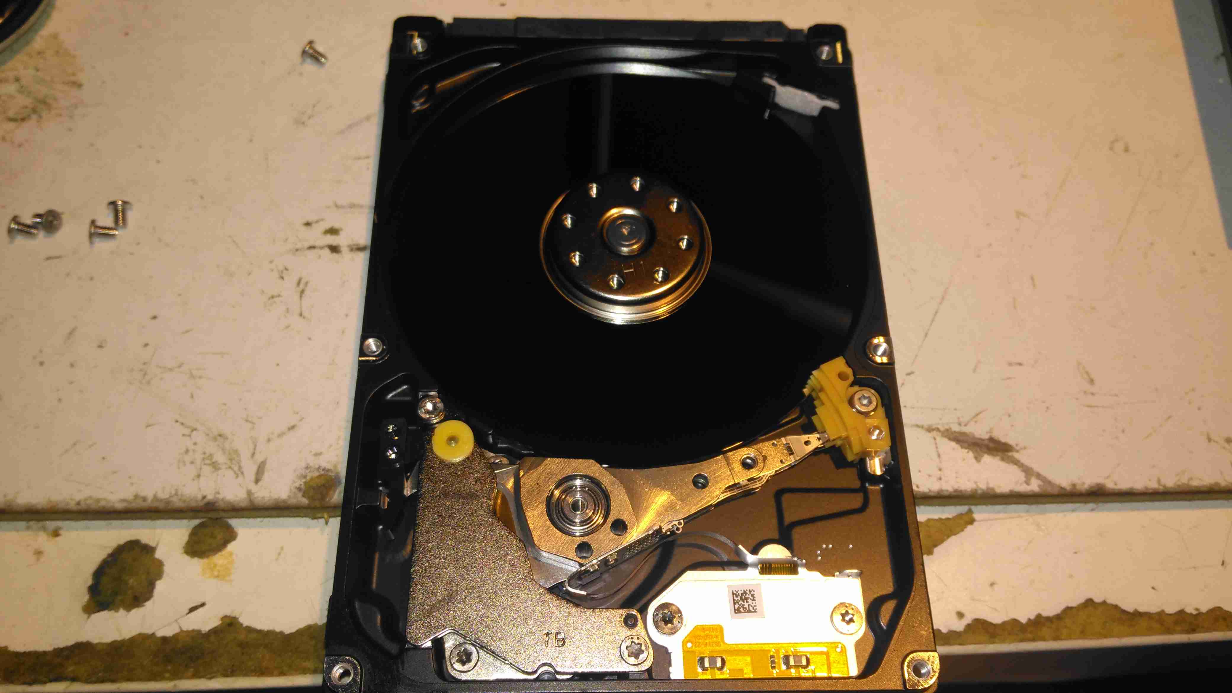
Internals
After pulling the lid on this disk, to see if there’s any evidence of a head crashing into a platter, there’s nothing – at least on a macroscopic scale, the single platter is pristine. I’ve seen disks crash to the point where the coating has been scrubbed from the platters so thoroughly that they’ve been returned to the glass discs they started off as, with the enclosure packed full of fine black powder that used to be data layer, but there’s no indication of mechanical failure here. Electronic failure is looking very likely.
Clearly, relying on SMART to alert when a disk is about to take a dive is an unwise idea, replacing drives after a set period is much better insurance if they are used for critical applications. Of course, current backups is always a good idea, no matter the age of drive.
I posted a while back a teardown of the VM Superhub 2 router, as VM has “upgraded” to a rebranded Arris TG2492S/CE CM. Alas Virgin Media in their wisdom have decided that simple router features like being able to change the LAN subnet & DHCP server range are far too complex to trust to the Great Unwashed, so they’ve removed them entirely from the firmware, and locked the local LAN onto the 192.168.0.0/24 range.
As my network is already numbered in the 10.0.0.0/16 range, with several statically addressed devices present and other systems relying on these static assignments, using this router would have meant renumbering everything.
Luckily Virgin had the decency to leave the “modem mode” option in the firmware, effectively disabling the WiFi & routing functions & allowing the connection of a third-party router. Some searching for a suitable replacement for the core of my network turned up the Linksys WRT1900ACS. While I waited for this to arrive, some temporary workarounds were needed to make everything function well enough with VM’s crap router.
WRT1900ACS
These routers have been designed as a modern replacement for the venerable WRT54G series of routers from some time ago, with full support for OpenWRT/DD-WRT firmware, and with a beefy 1.6GHz dual core CPU & 512MB of RAM I doubt I’ll be able to knock this one over with too much network traffic! This was pretty much the most powerful router I could afford, and should mean I don’t need to upgrade for a long time. (No teardown of this yet, as it’s taking care of the network at present. Maybe some point in the future I’ll take the plunge).
The stock firmware isn’t totally awful, and has some nice features, but I decided it needed to be replaced with DD-WRT for more security & future flexibility. I’ll leave the firmware flashing stuff for another post 😉
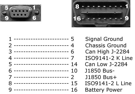
As I mentioned in the previous post, these heaters have a standard interface that’s used for control & diagnostics, the W-Bus. This is transmitted over the K-Line of the vehicle bus, and all heaters, regardless of firmware modifications done by the various car manufacturers respond to this interface. Official Webasto diagnostic adaptors are available, but these are just a very expensive serial adaptor. A much cheaper option is a ~£5 Universal ODB adaptor.
ODB2
Above shows the signals on the ODB connector – the ones we’re interested in here are Pin 16, the +12v supply, and Pin 7, K-Line. Connect Pin 16 to the positive supply to the heater, and Pin 7 to Pin 2 on the Webasto heater. (Valid for all TT-V heaters).
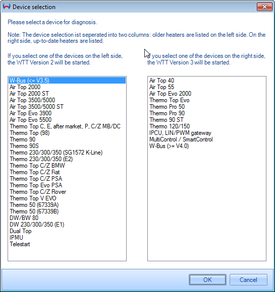
Device Selection
Once these two connections are made to the heater, fire up the Thermo Test software. The screen above will be displayed. Pick W-Bus at top left.
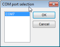
COM Port Selection
First thing, connect the ODB adaptor to USB, and change to the correct COM port in Thermo Test. There may be several in the list, but a newly connected USB device should show up with the highest COM number.
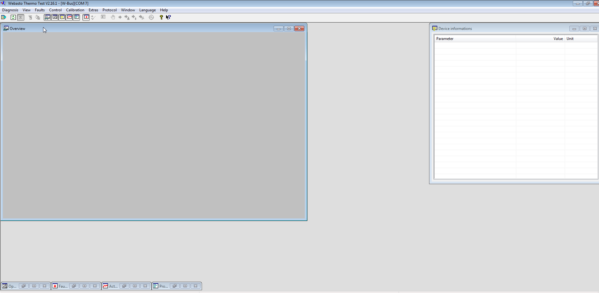
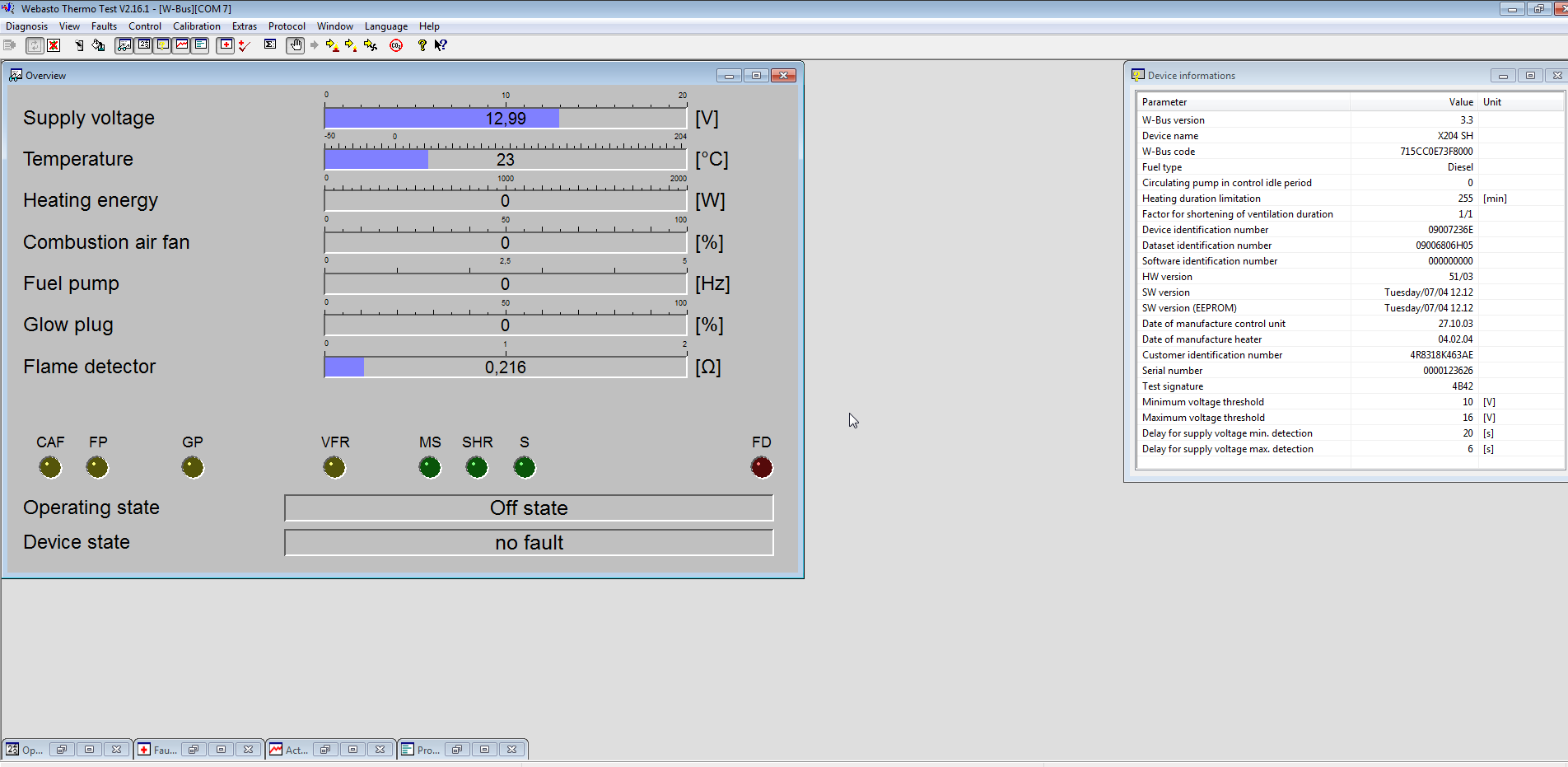
Thermo Test
Once Thermo Test is running, start communications by going to the Diagnosis Menu > Start Diagnostic (F2 keyboard shortcut).
Initialized
After a few seconds, communication will be established. This will show faults, if any are present, and allow testing of the heater & it’s component parts. A summary report can be generated with Diagnosis > View Summary:
Diagnosis report                                               Webasto Thermosystems
------------------------------------------------------------------------------------------


Configuration:
--------------
  W-Bus version...............................................................3.3
  Device name.............................................................X204 SH
  W-Bus code.......................................................715CC0E73F8000
  Fuel type................................................................Diesel
  Circulating pump in control idle period.......................................0
  Heating duration limitation.................................................255 [min]
  Factor for shortening of ventilation duration...............................1/1
  Device identification number..........................................09007236E
  Dataset identification number.......................................09006806H05
  Software identification number........................................000000000
  HW version................................................................51/03
  SW version..................................................Tuesday/07/04 12.12
  SW version (EEPROM).........................................Tuesday/07/04 12.12
  Date of manufacture control unit.......................................27.10.03
  Date of manufacture heater.............................................04.02.04
  Customer identification number.....................................4R8318K463AE
  Serial number........................................................0000123626
  Test signature.............................................................4B42
  Minimum voltage threshold....................................................10 [V]
  Maximum voltage threshold....................................................16 [V]
  Delay for supply voltage min. detection......................................20 [s]
  Delay for supply voltage max. detection.......................................6 [s]

Operating data:
---------------
  Working hours.............................................................44:03 [h:m]
  Operating hours.........................................................5388:08 [h:m]
  Start count...............................................................19129
  Burning duration PH 1..33%.................................................0:00 [h:m]
  Burning duration PH 34..66%................................................0:00 [h:m]
  Burning duration PH 67..100%...............................................0:00 [h:m]
  Burning duration PH >100%..................................................0:00 [h:m]
  Burning duration SH 1..33%.................................................0:00 [h:m]
  Burning duration SH 34..66%................................................0:00 [h:m]
  Burning duration SH 67..100%...............................................0:00 [h:m]
  Burning duration SH >100%..................................................0:00 [h:m]
  Working duration PH........................................................0:51 [h:m]
  Working duration SH......................................................121:10 [h:m]
  Start counter PH..............................................................6
  Start counter SH............................................................854
  Ventilation duration.......................................................0:00 [h:m]

Error:
------

------------------------------------------------------------------------------------------
12.03.17  17:17:30                                       Webasto Thermo Test  2.16.1
This shows all the important stuff, including running hours. (5388Hrs on this heater!). Most importantly, there are no faults listed.
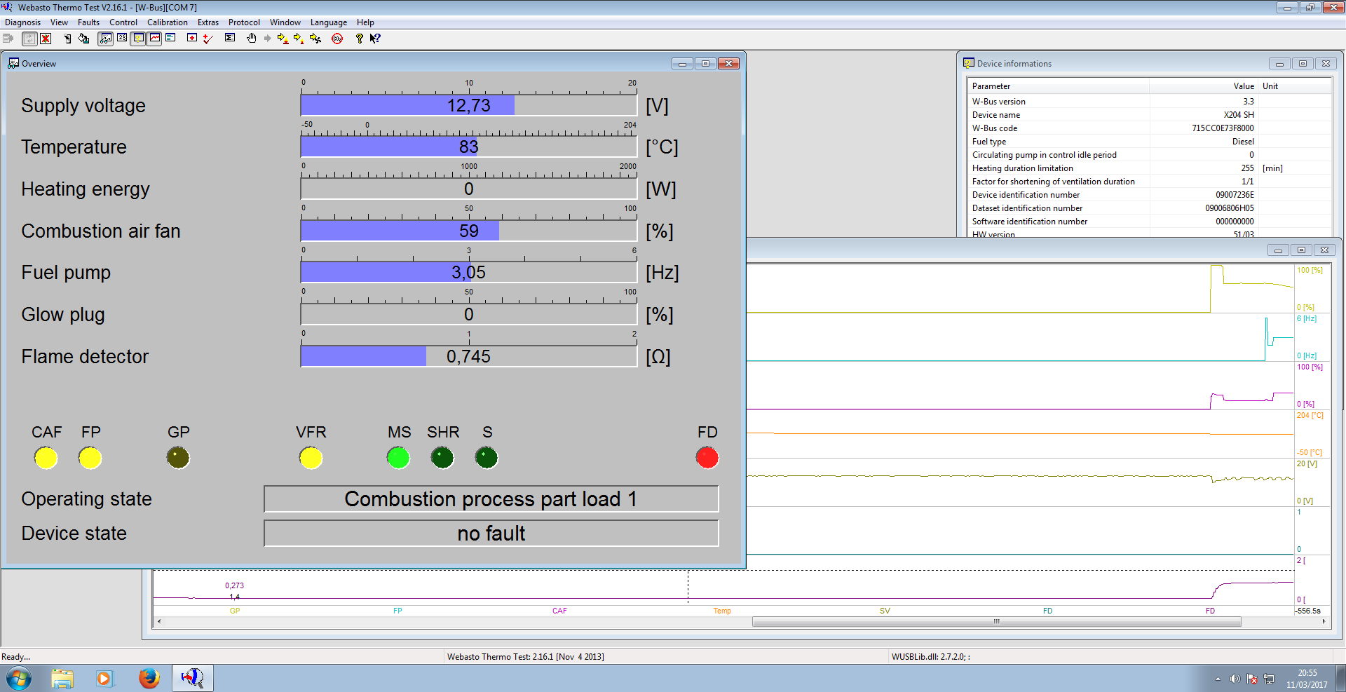
Heater Running
The heater can be fully tested by issuing a start command from the Command Menu > Parking Heating option. Obviously cooling water will be required for this, along with an external water pump. (The water pump control output on these heaters seems to be totally disabled in firmware, as they rely on the engine’s coolant pump). I used a bucket of water along with a small centrifugal pump to provide the cooling. During this test I noted that the firmware is much more aggressive in these units. The marine versions shut down at ~72°C water temperature, whereas these don’t so the same until ~90°C.
Now I’ve managed to communicate with the heater, I’ll get onto building a standalone controller so I can dispense with the Windows VM for control.
I was recently given this unit, along with another Behringer sound processor to repair, as the units were both displaying booting problems. This first one is a rather swish Mastering Processor, which has many features I’ll leave to Behringer to explain 😉
Input Board & Relays
All the inputs are on the back of this 19″ rackmount bit of kit, nothing much on this PCB other than the connectors & a couple of switching relays.
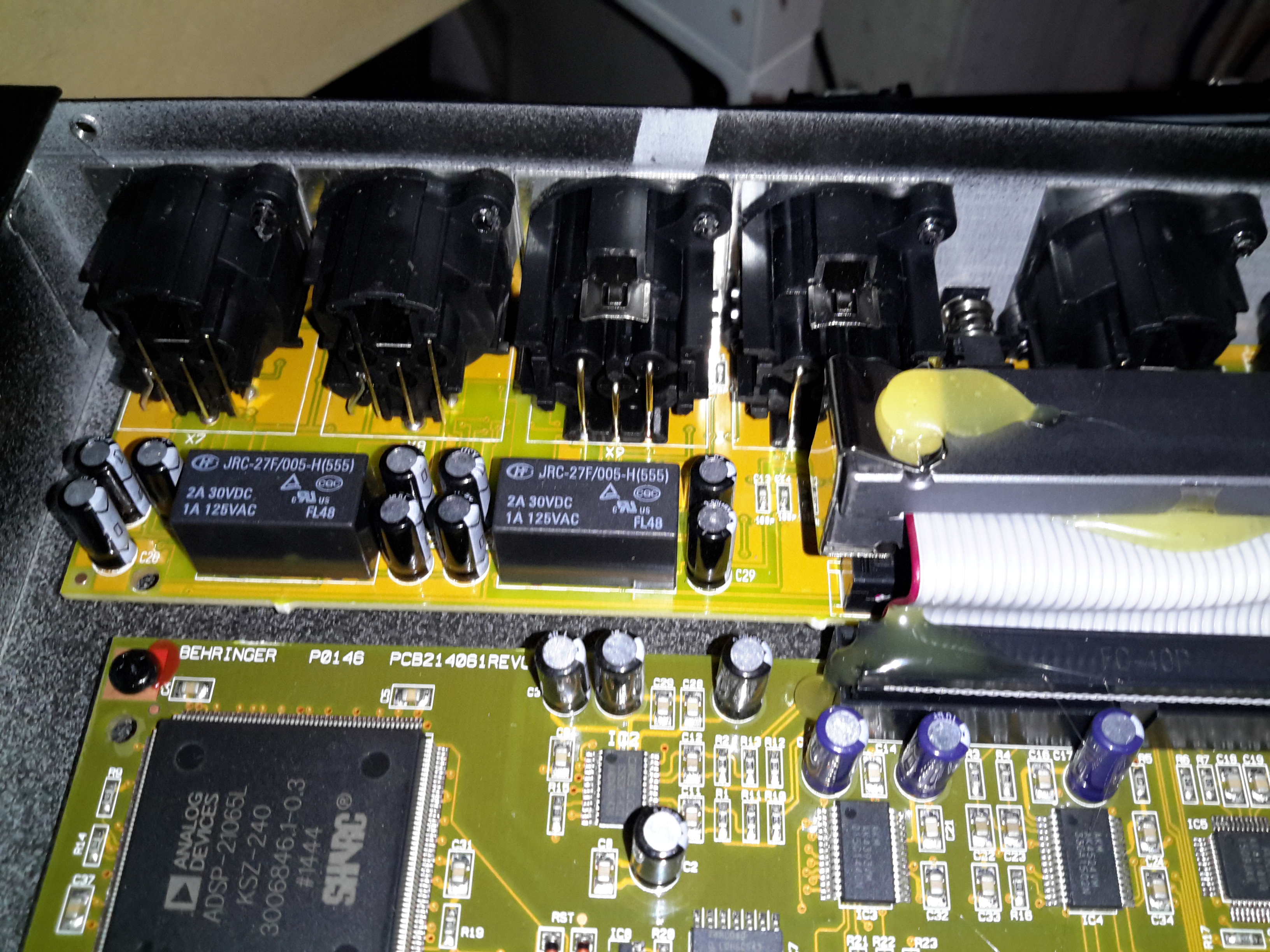
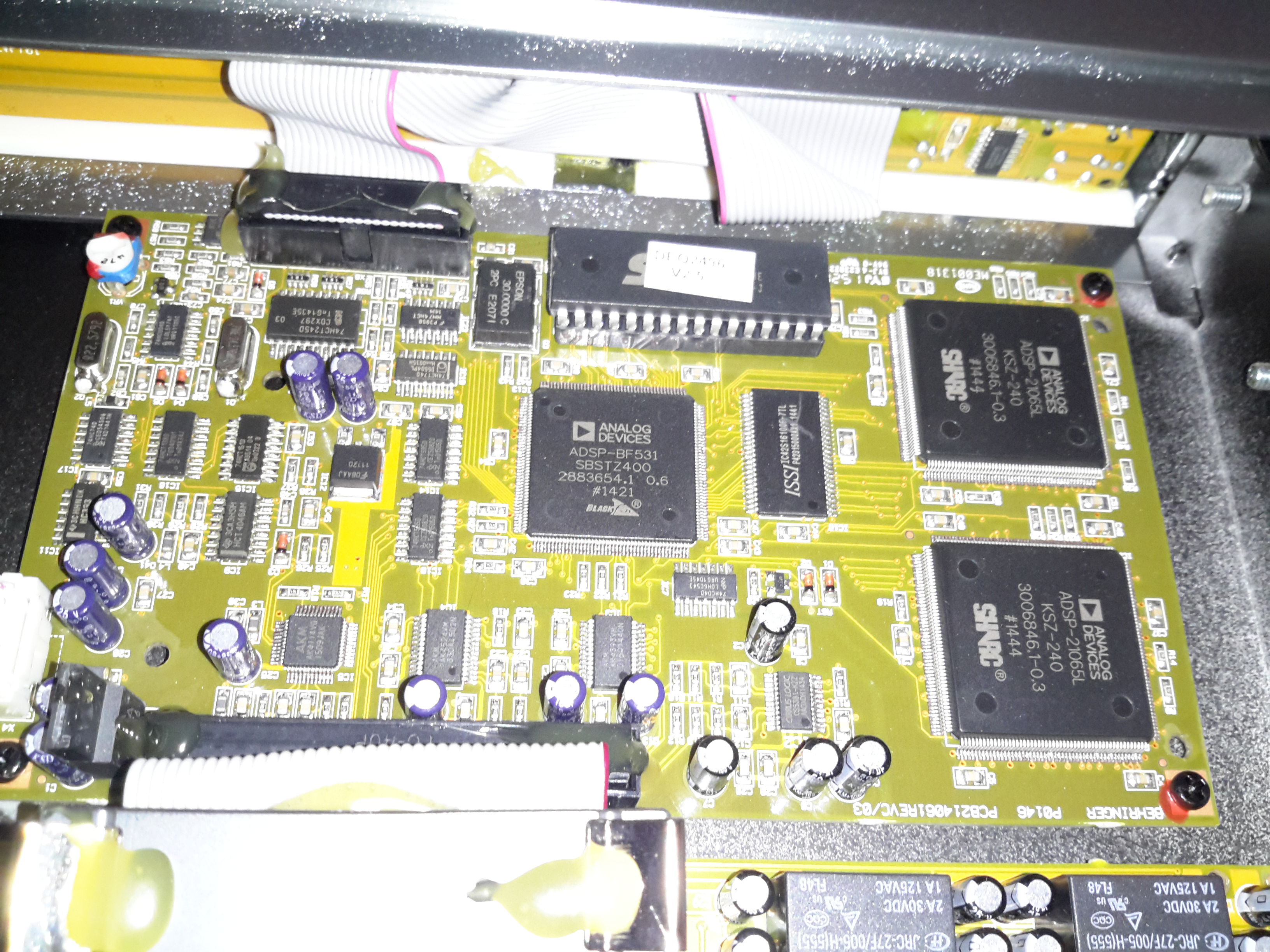
Main Processor PCB
All the magic is done on the main processor PCB, which is host to 3 Analog Devices DSP processors:
ADSP-BF531 BlackFin DSP. This one is probably handling most of the audio processing, as it’s the most powerful DSP onboard at 600Mhz. There’s a ROM on board above this for the firmware & a single RAM chip. On the right are a pair of ADSP-21065 DSP processors at a lower clock rate of 66MHz. To the left is some glue logic to interface the user controls & dot-matrix LCD.
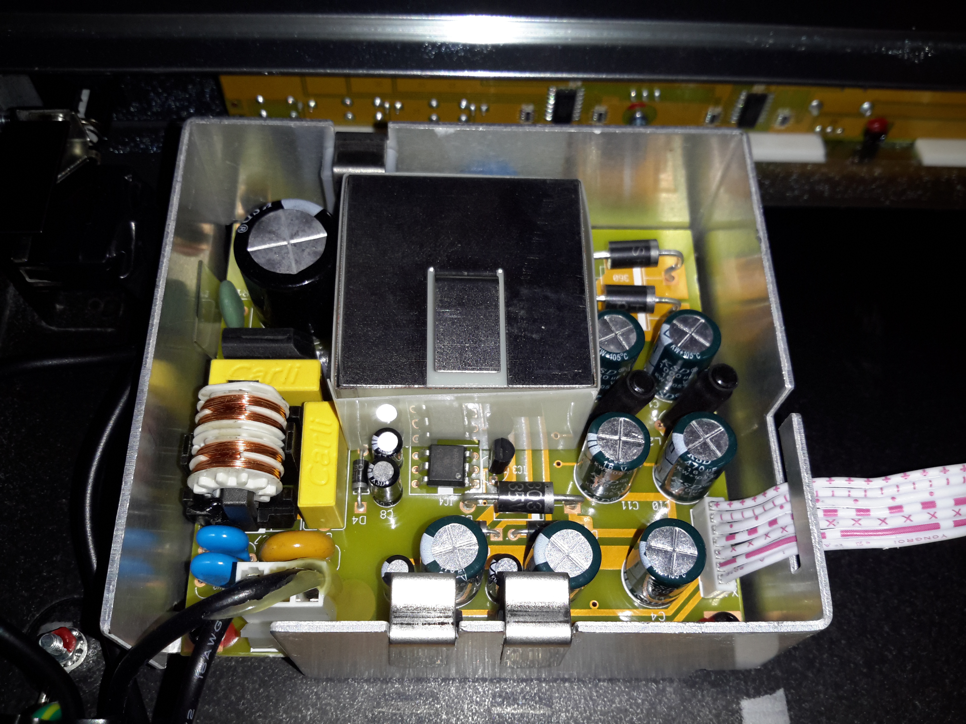
PSU Module
The PSU in this unit is a pretty standard looking SMPS, with some extra noise filtering & shielding. The main transformer is underneath the mu-metal shield in the centre of the board.
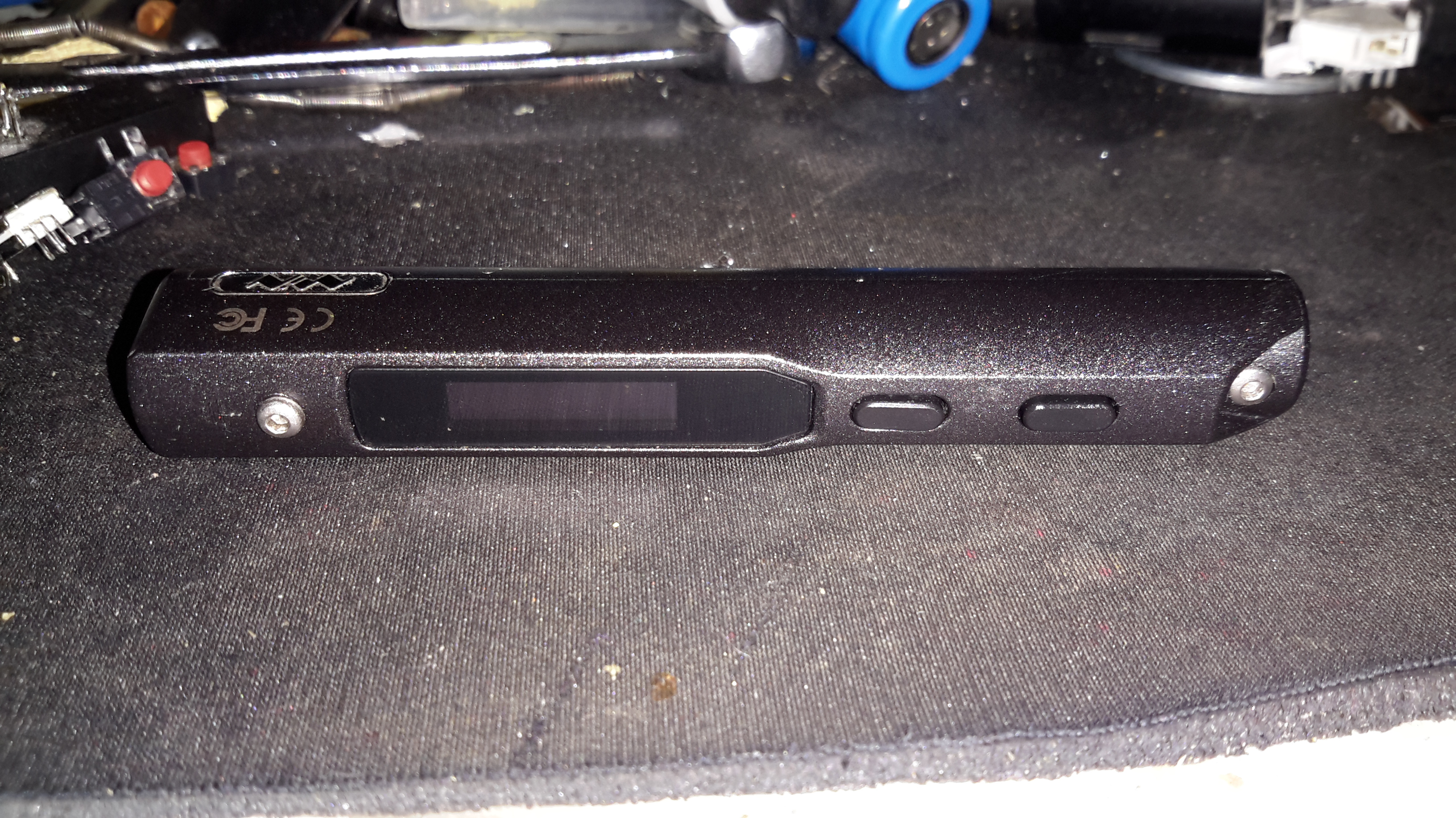
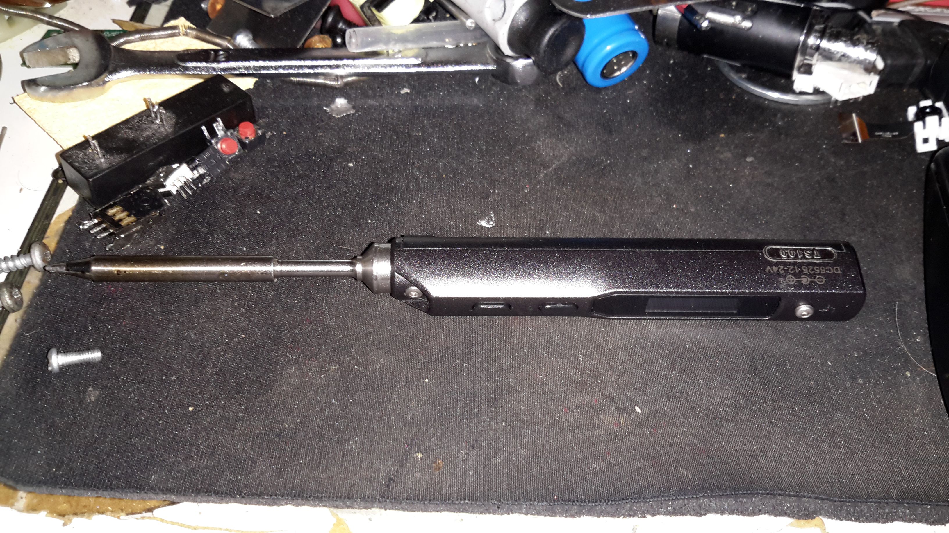
When I ordered the tiny USB soldering iron, I decided a proper iron upgrade would be a good idea. Looking around for something that didn’t require AC mains power turned up the TS100, a Chinese design, that unusually is actually very good! Above is the handle itself, with it’s small OLED display & two operation buttons.
This iron is controlled by a STM32 ARM microcontroller, the firmware & schematics are completely open-source.
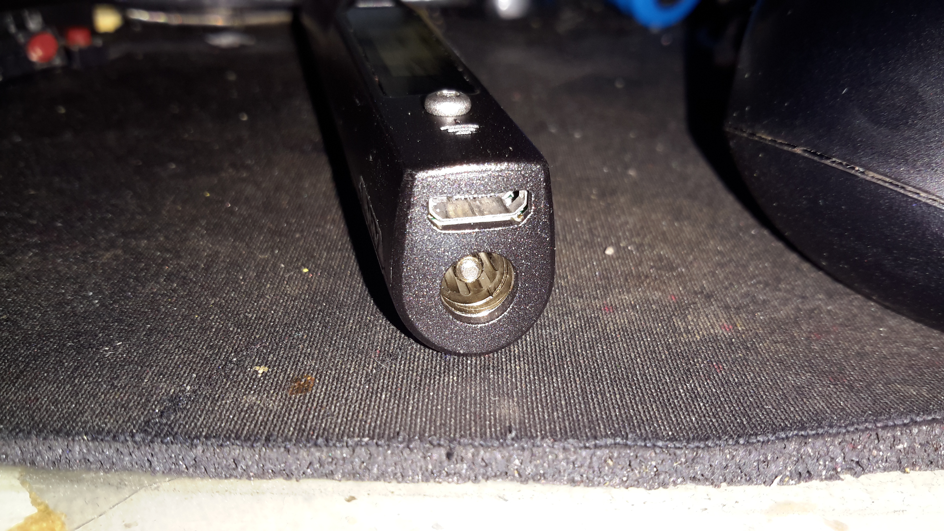
DC Input Jack / USB Port
The bottom end of the iron has the main DC input jack, designed with laptop chargers in mind (DC input range from 10v-24v). Above that is the micro USB port for programming.
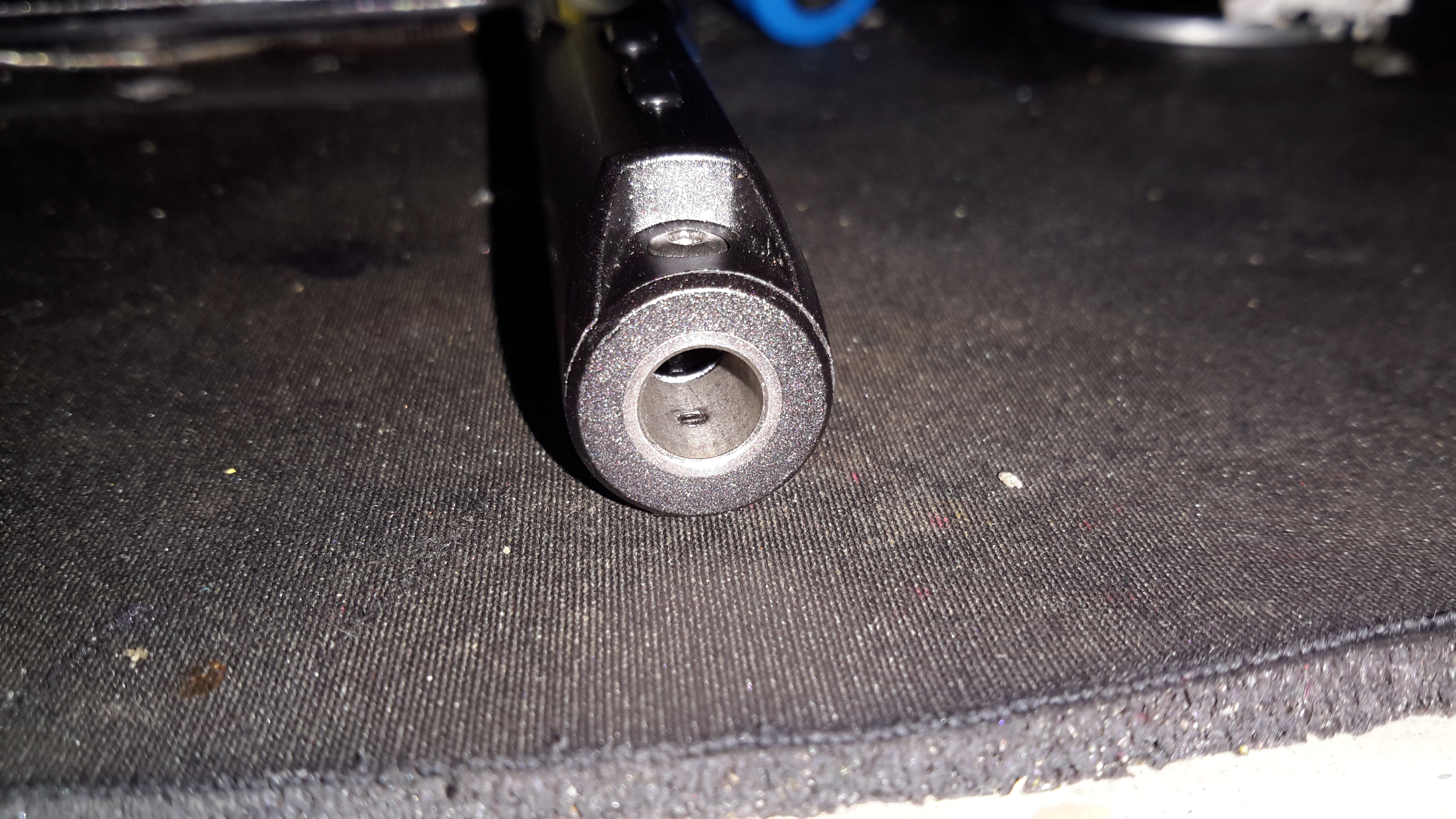
Heating Element Socket
The iron tips slot into the other end, many different tip types & shapes are available. The one supplied was the simple conical tip.
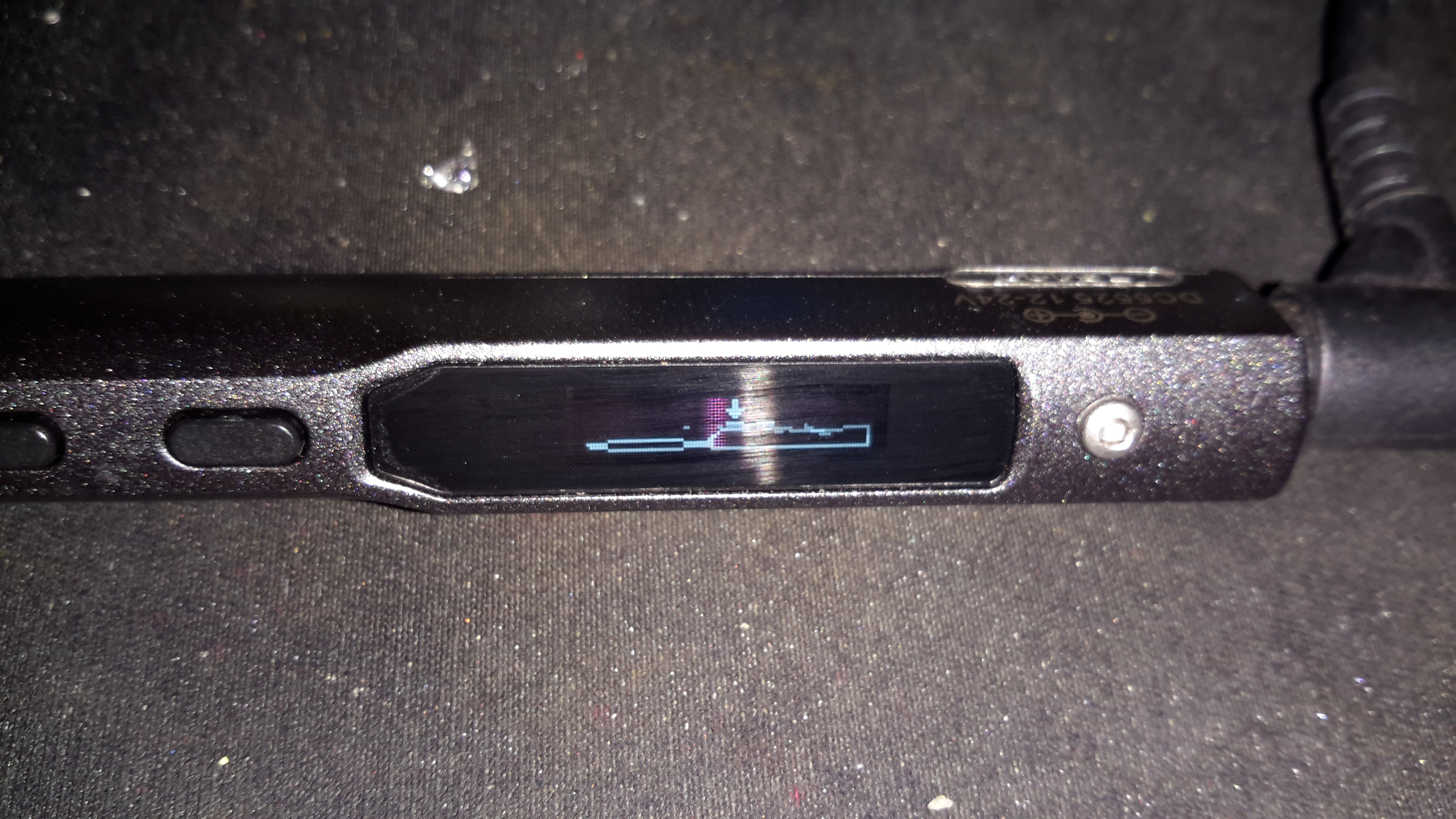
Standby Screen
Plugging the iron into some power gets a standby screen – it doesn’t just start heating immediately, for safety.
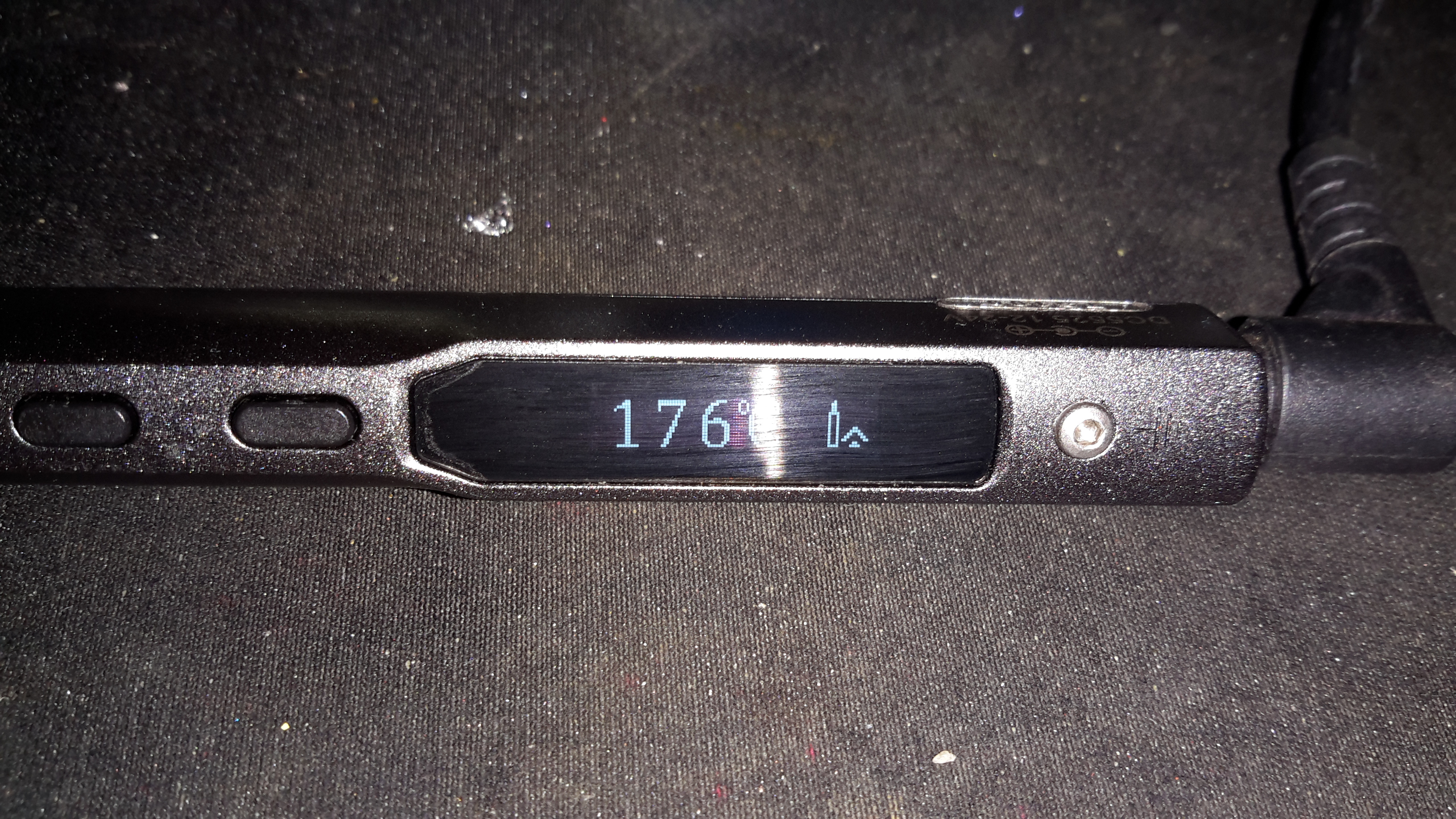
Heating
The left hand button starts the heater, which on a 24v input voltage gets to operating temperature well within 10 seconds.
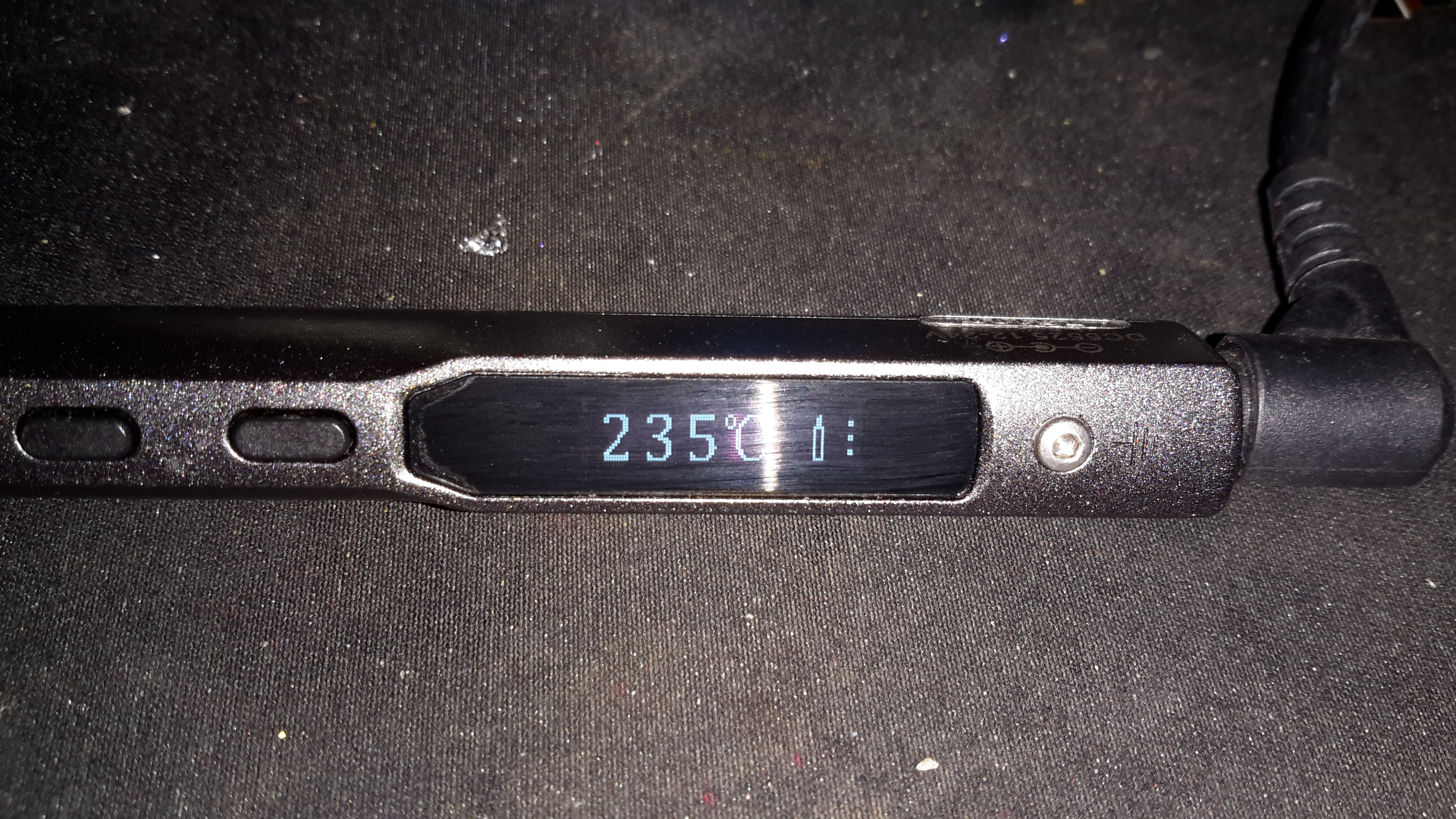
Temperature Stable
The right hand screen icon changes when the temperature has stabilized. The control PCB has an integrated accelerometer, leaving the iron hot for a few minutes triggers a timeout & it powers down. Once picked up again, the heater instantly restarts.
The operating temperature is adjustable with the pair of buttons, from 100°C to 400°C.
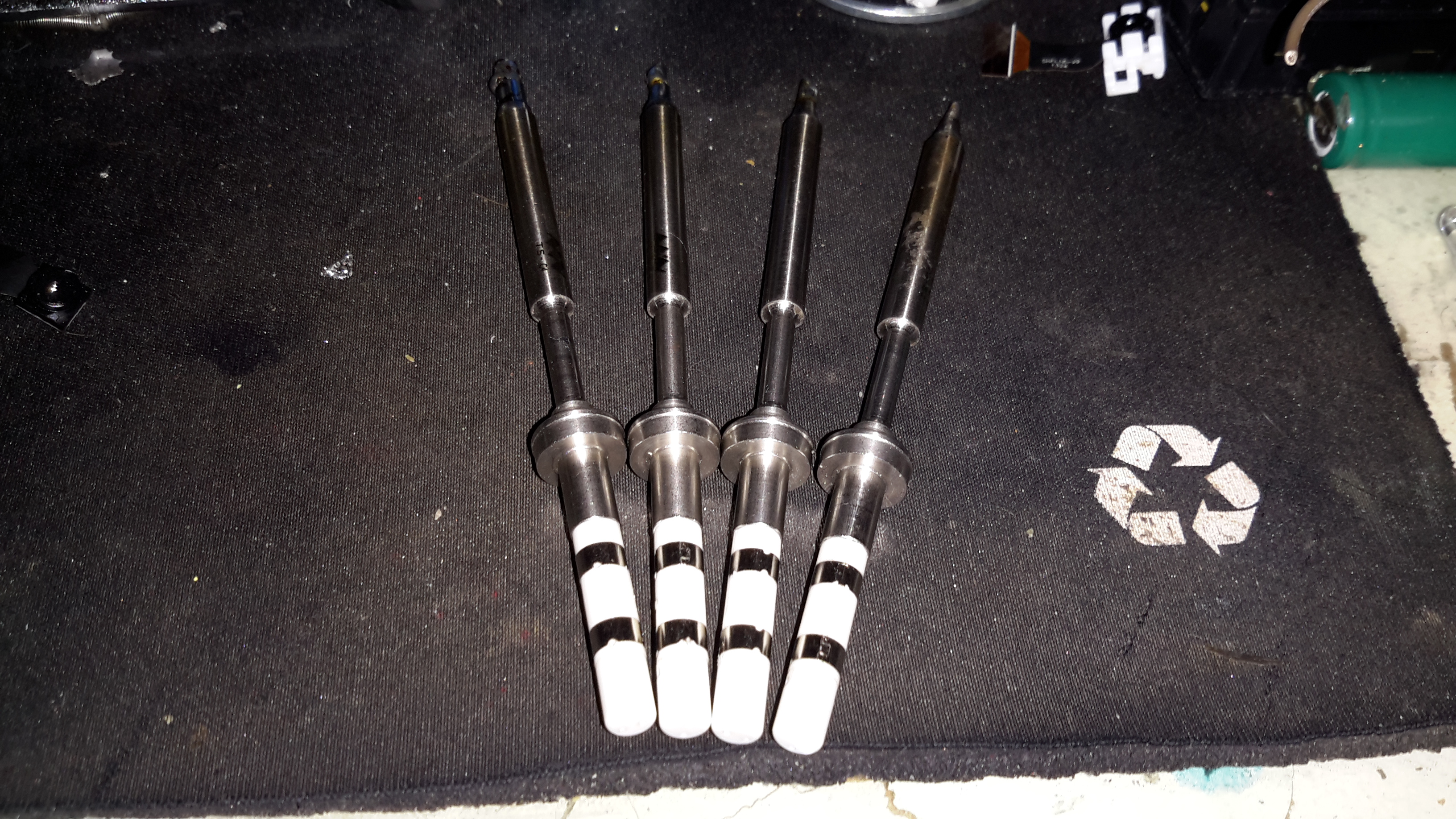
Different Bits
Here’s a selection of bits for the iron. The design is very similar to the Hakko T15 series of irons, but these are a much shorter version. Like the Hakko versions, the actual tips aren’t replaceable, once the bit burns out, the entire assembly is replaced.
TS100 Soldering Iron
Here’s the iron fully assembled. The entire device is about the same length as just the heating element from a Hakko T15!
It’s official. I’m now part of the uRadMonitor network, & assisting in some of the current issues with networking some people (including myself) have been having.
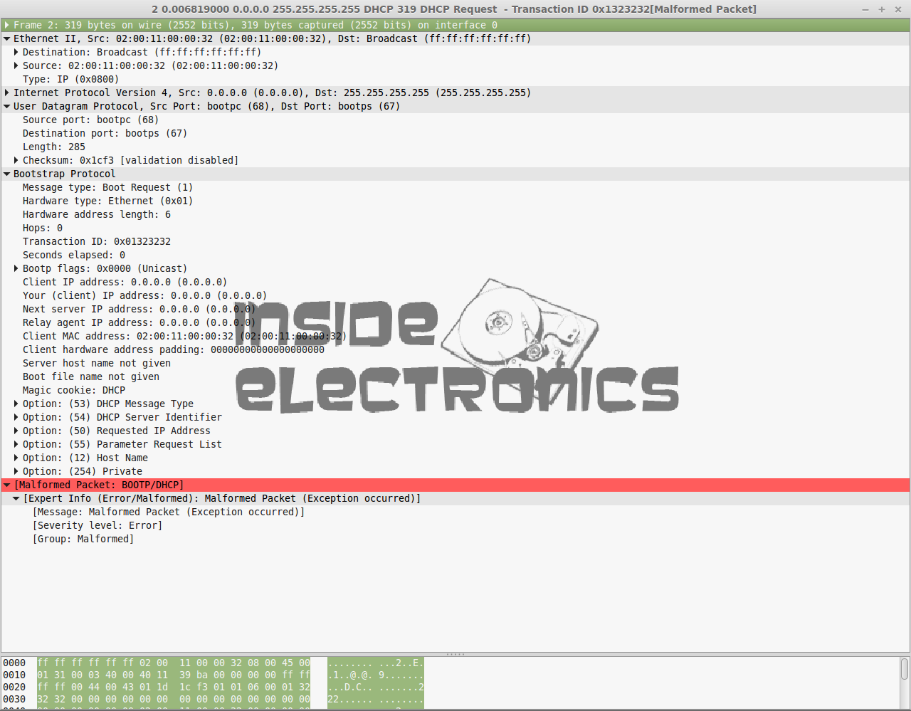
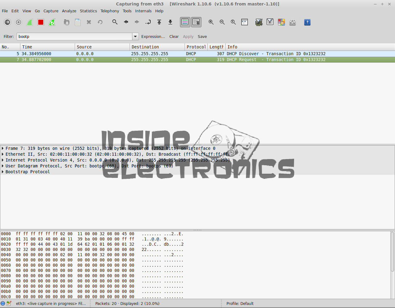
It seems that the uRadMonitor isn’t sending out technically-valid DHCP requests, here is what Wireshark thinks of the DHCP on my production network hardware setup:
WireShark Screencap
As can be seen, the monitor unit is sending a DHCP request of 319 bytes, where a standard length DHCP Request packet should be ~324 bytes, as can be seen on the below screen capture.
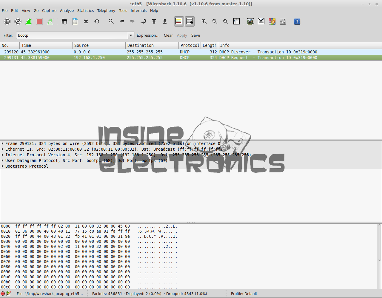
Valid DHCP
This valid one was generated from the same SPI Ethernet module as the monitor, (Microchip ENC28J60) connected to an Arduino. Standard example code from the EtherCard library was used to set up the DHCP. The MAC address of the monitor was also cloned to this setup to rule out the possibility of that being the root cause.
My deductive reasoning in this case points to the firmware on the monitor being at fault, rather than the SPI ethernet hardware, or my network hardware. Radu over at uRadMonitor is looking into the firmware being at fault.
Strangely, most routers don’t seem to have an issue with the monitor, as connecting another router on a separate subnet works fine, and Wireshark doesn’t even complain about an invalid DHCP packet, although it’s exactly the same.
Working DHCP
As the firmware for the devices isn’t currently available for me to pick apart & see if I can find the fault, it’s up to Radu to get this fixed at the moment.
Now, for a µTeardown:
uRadMonitor
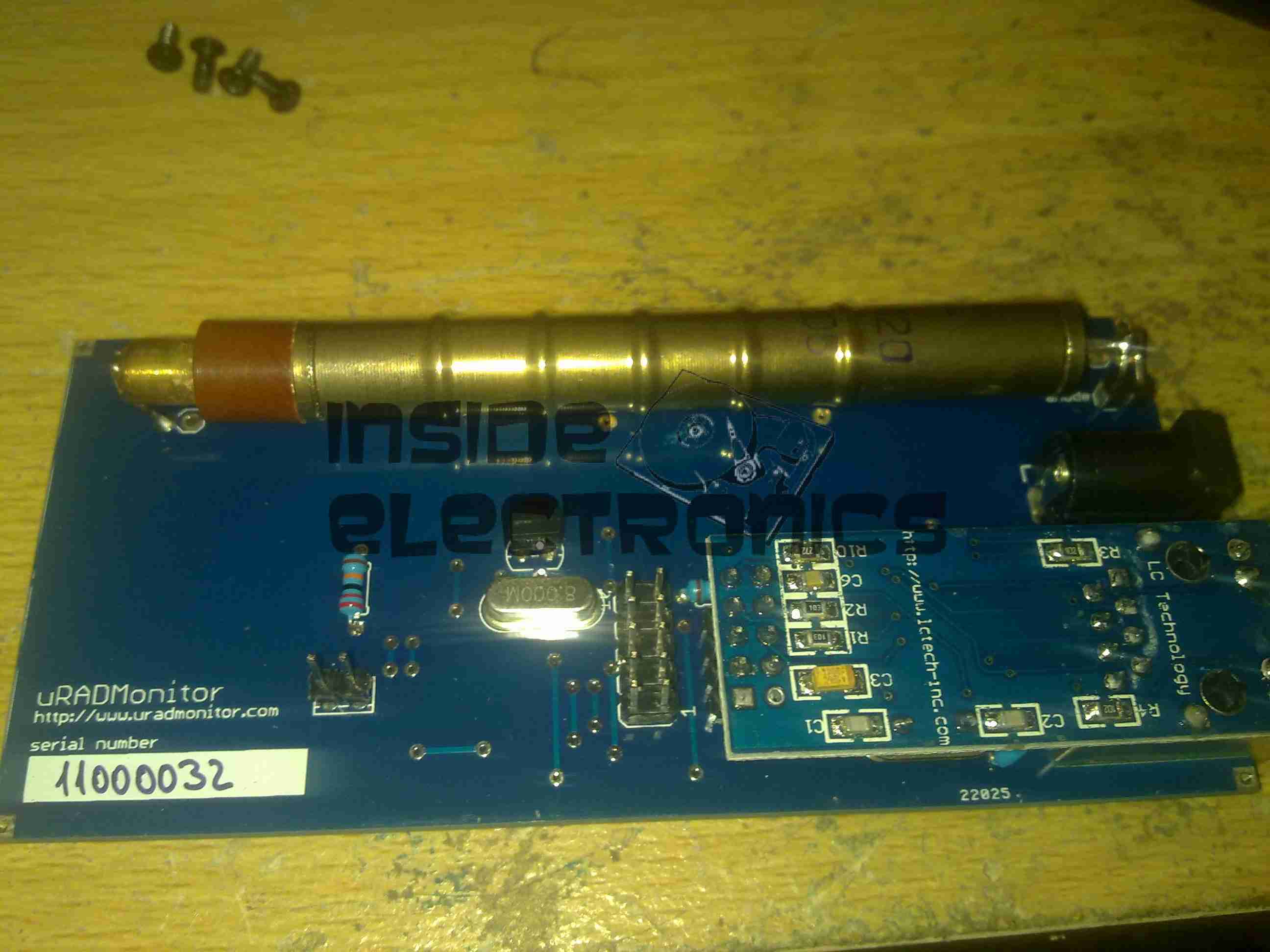
Here is the monitor, a small aluminium box, with power & network.
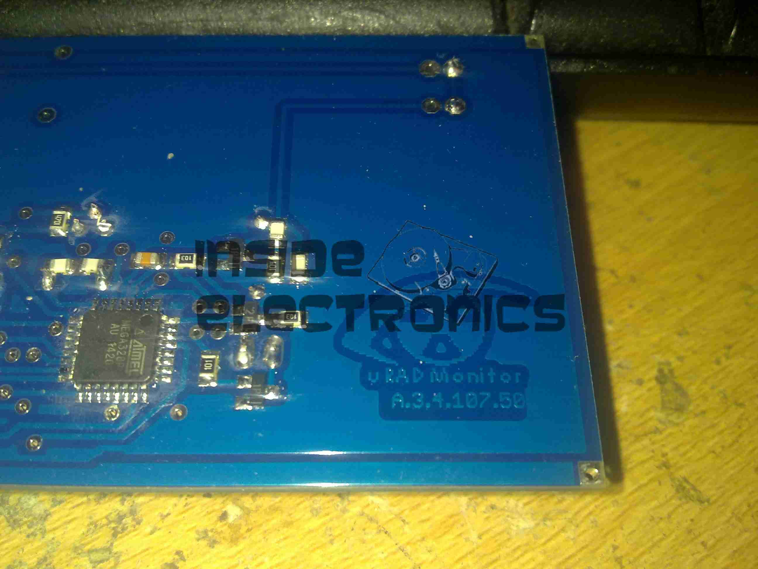
PCB
Removing 4 screws in the end plate reveals the PCB, with the Geiger-Mueller tube along the top edge. My personal serial number is also on the PCB.
The ethernet module is on the right, with the DC barrel jack.
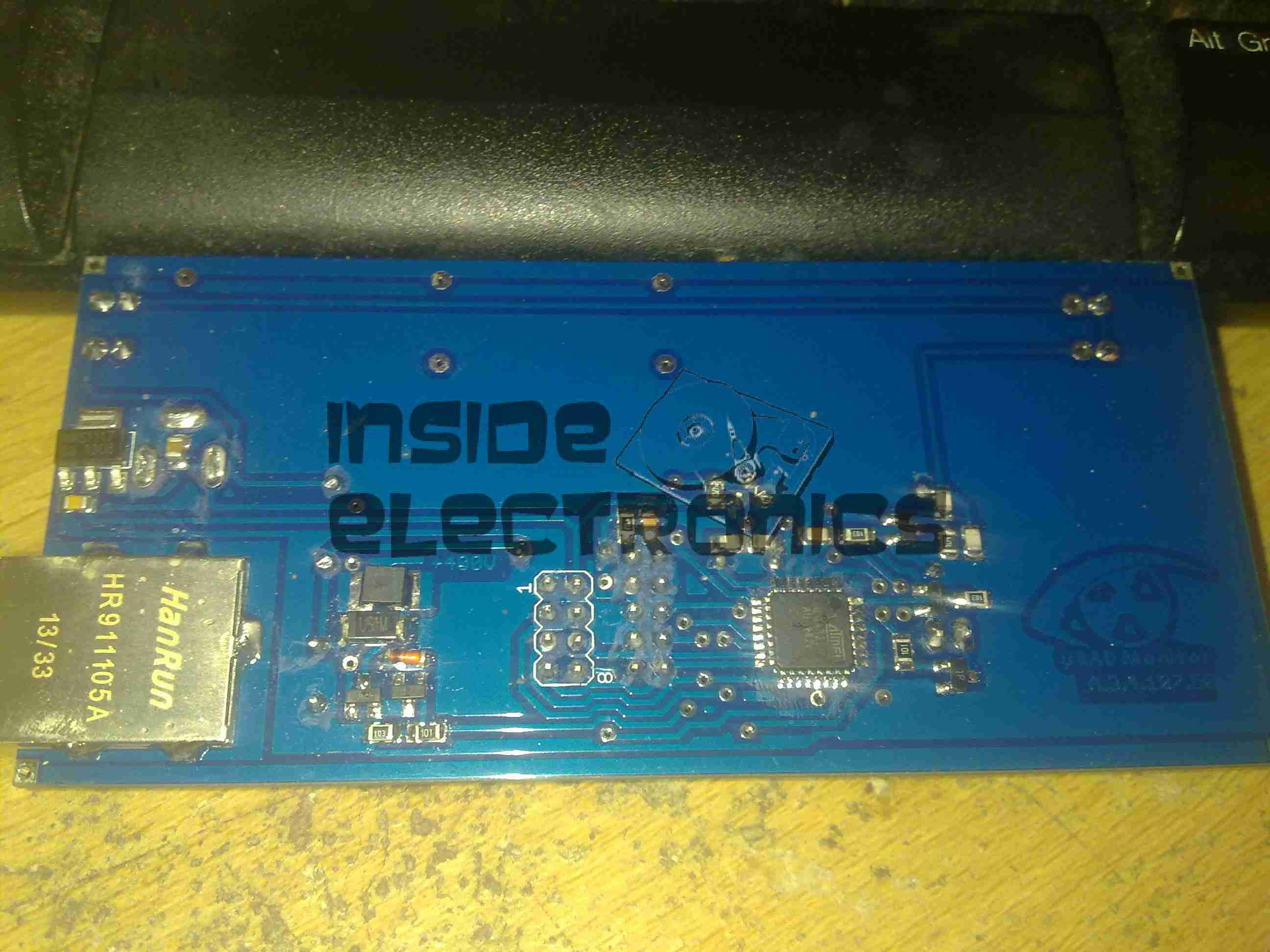
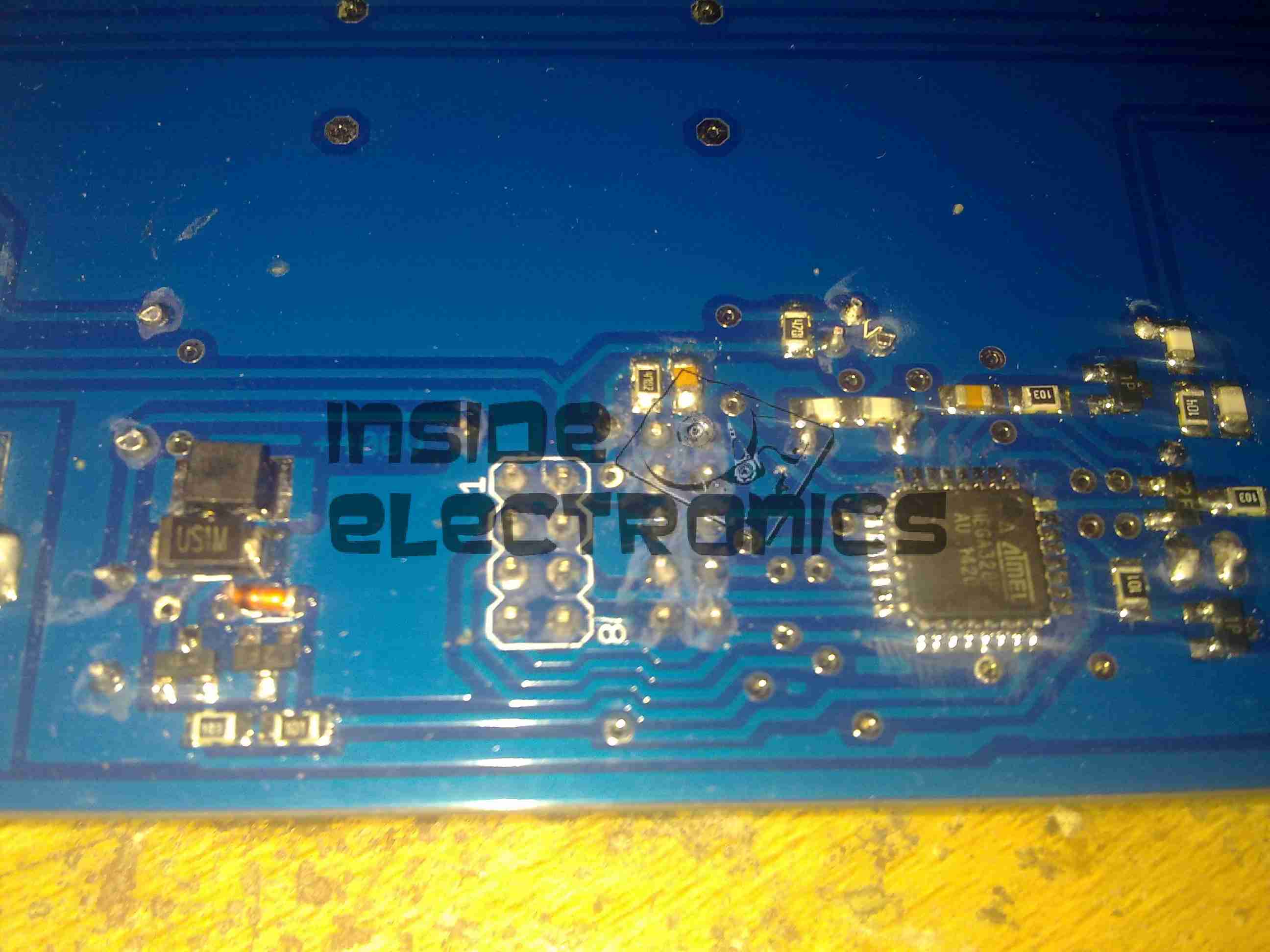
PCB Bottom
Here is the bottom of the PCB, with the control MCU & the tiny high voltage inverter for the Geiger tube.
Here is an AVR powered optical tachometer design, that I adapted from the schematic found here.
I made a couple of changes to the circuit & designed a PCB & power supply module to be built in. The original design specified a surface mount IR LED/Photodiode pair, however my adjustment includes a larger IR reflectance sensor built onto the edge of the board, along with a Molex connector & a switch to select an externally mounted sensor instead of the onboard one.
There is also an onboard LM7805 based power supply, designed with a PCB mount PP3 battery box.
The power supply can also be protected by a 350mA polyfuse if desired. If this part isn’t fitted, then a pair of solder bridge pads are provided within the footprint for the fuse to short out the pads.
For more information on the basic design, please see the original post with the link at the top of the page.
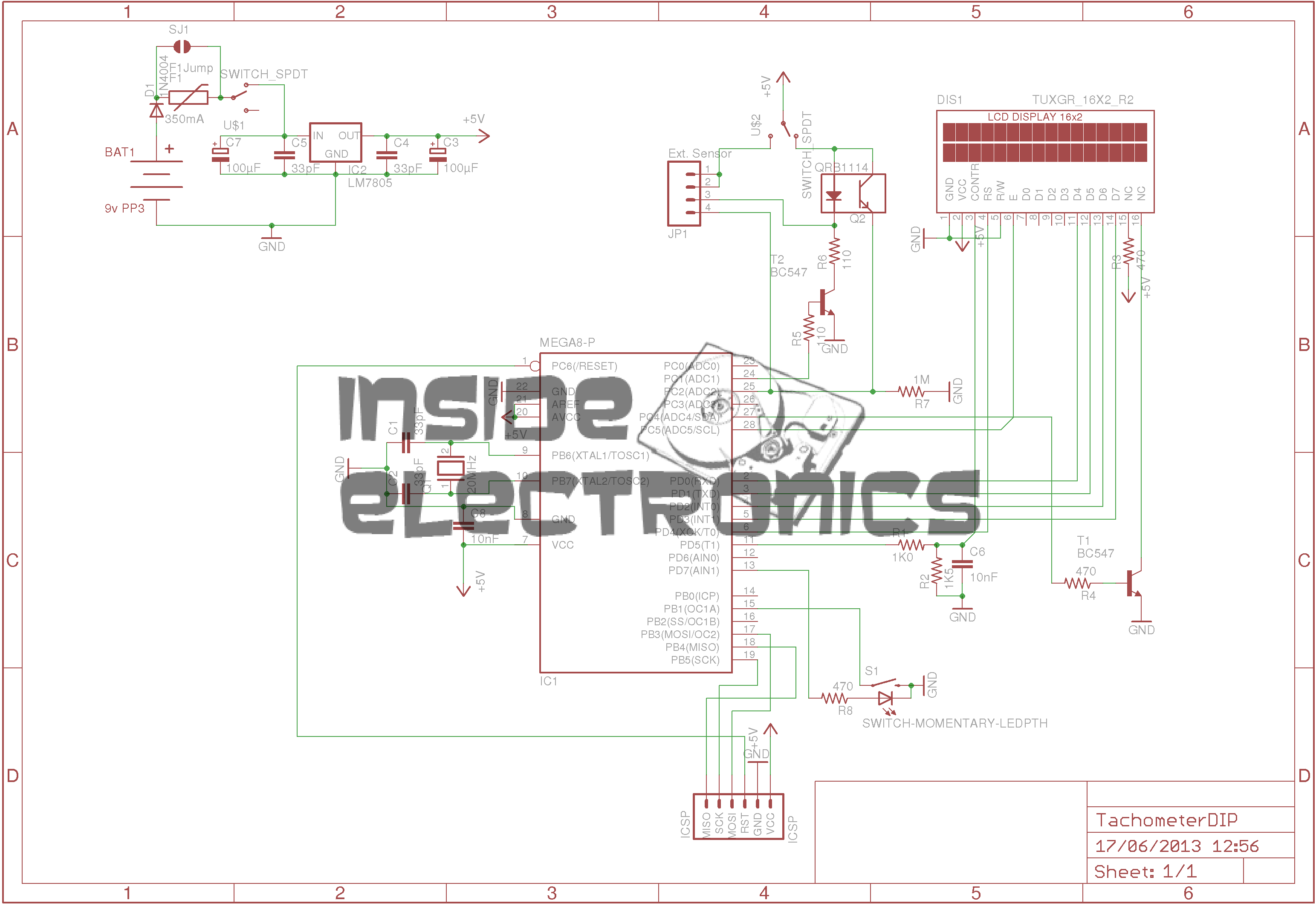
Schematic
Here is an archive of the firmware & the Eagle CAD files for the PCB & schematic design.
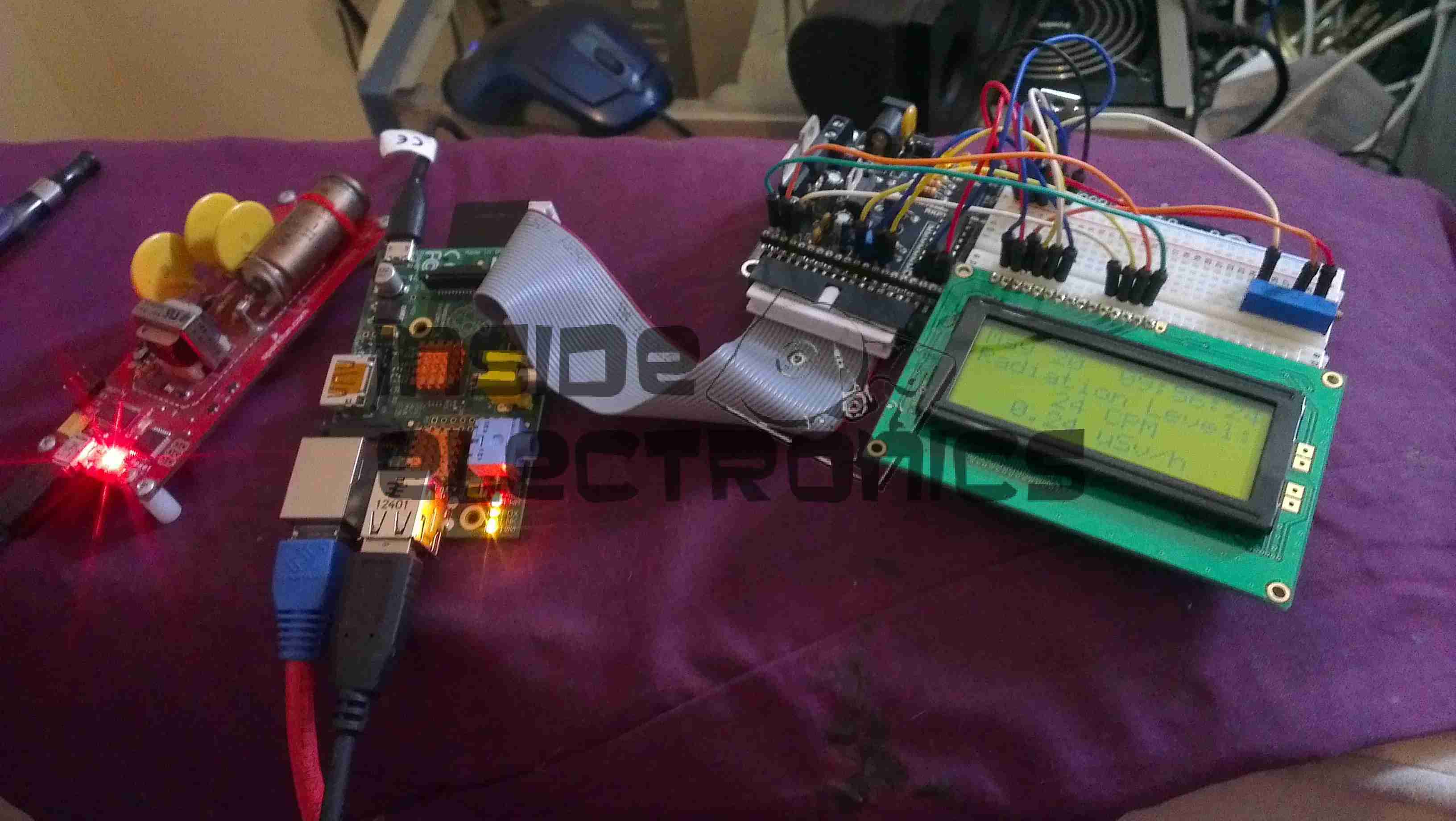
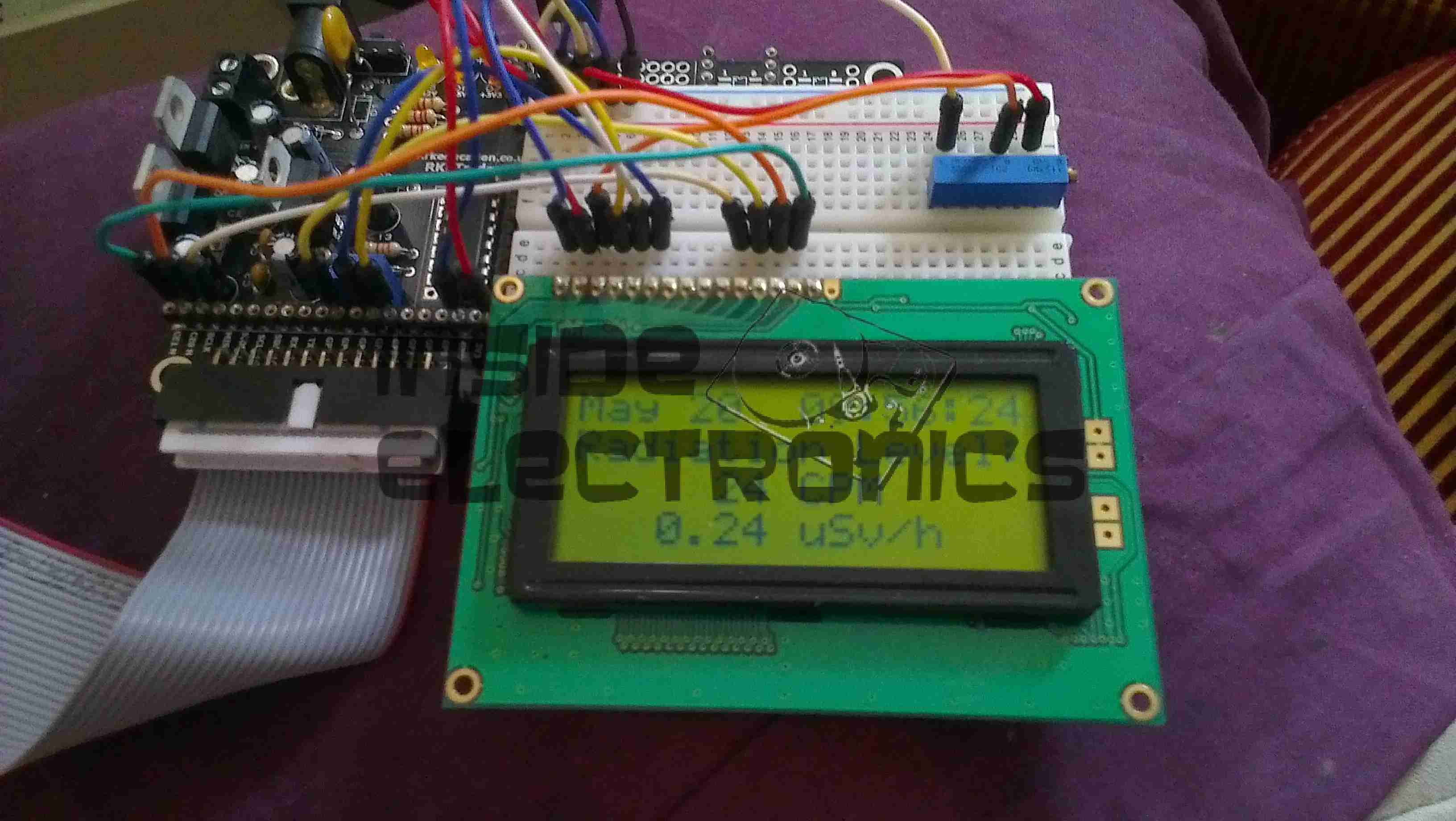
Here’s my latest project with the Pi: interfacing it with the Sparkfun Geiger counter & outputting the resulting data to a character LCD.
The geiger counter is interfaced with it’s USB port, with the random number generator firmware. A Python script reads from the serial port & every minute outputs CPM & µSv/h data to the display.
The Python code is a mash of a few different projects I found online, for different geiger counters & some of my own customisations & code to write the info to the display & convert CPM into µSv/h.
This also writes all the data into a file at /var/log/radlog.txt
This is the Velleman MK179 Proximity Card Reader, which is supplied in kit form. In the image above you can see the completed kit, the read coil is etched onto the black PCB on the left. Bringing a recognised card close to the coil operates the relay on the main PCB for a programmable amount of time.
Main PCB
Closeup of the main PCB, 12v DC input at top right. Left IC is an LM358 dual Op-Amp, the IC on the right is a PIC12F629 with Velleman’s custom firmware.
Logic power is supplied to the ICs & the oscillator from the LM7805 regulator at the top of the PCB. The relay is a standard 15A SPDT 12v coil relay, with the switch contacts broken out onto the screw terminals on the left.
Schematic Diagram
As it is not provided with the kit, unlike other Velleman kits, here is the schematic for this.
This is a Western Digital drive recently removed from my laptop when it died of a severe head crash.
Top of drive can be seen here.
Top Removed
Here the cover has been removed from the drive, showing the platter, head arm & magnet. Yellow piece top left is head parking ramp.
Head Arm
The head assembly of the drive is shown here. The head itself is on the left hand end of the arm in the plastic parking ramp. The other end of the arm holds the voice coil part of the head motor, surrounded by the magnet.
Bottom Of Drive with PCB
Bottom of drive, with controller PCB. SATA interface socket at bottom.
PCB removed from bottom of drive. Spindle motor connections & connections to the head unit can be seen on the bottom of the drive unit.
Controller PCB. Supports the cache, interface & motor controller ICs.
Closeup of the motor driver IC, this controls the speed of the spindle motor precisely to 5,400RPM. Also controls the voice coil motor controlling the position of the head arm on the platters.
Interface IC closeup. This IC receives signals from the head assembly & processes them for transmission to the SATA bus. Also holds drive firmware, controls the Motor driver IC & all other functions of the drive.
Cache Memory IC.
Tip Jar
If you’ve found my content useful, please consider leaving a donation by clicking the Tip Jar below!
All collected funds go towards new content & the costs of keeping the server online.