Posted on 2 Comments

EpEver MT50 Control Panel Teardown

MT50 Control Panel
MT50 Control Panel

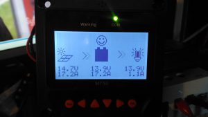
Here’s the MT50 controller from EpEver, that interfaces with it’s Tracer MPPT solar charge controllers, and gives access to more programming options on the charge controllers, without the need for a laptop. The display is a large dot-matrix unit, with built in backlight. Above is the display on the default page, showing power information for the entire system.
PCB Rear
PCB Rear

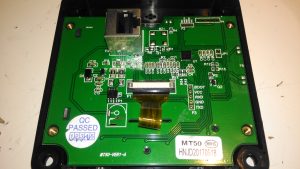
The rear plastic cover is held in place by 4 machine screws, which thread into brass inserts in the plastic frame – nice high quality touch on the design here, no cheap self tapping plastic screws. Both power & data arrive via an Ethernet cable, but the communication here is RS-485, and not compatible with Ethernet! The PCB is pretty sparse, with comms & power on the left, LCD connection in the centre, and the microcontroller on the right.
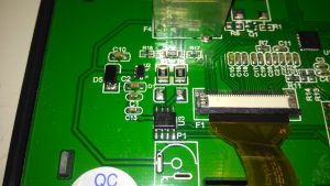
RS-485 Transceiver
RS-485 Transceiver

On the left of the board is the RS0485 transceiver, and a small voltage regulator. There’s also a spot for a DC barrel jack, which isn’t included in this model for local power supply.
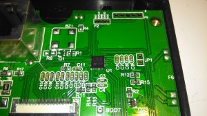
STM32 Microcontroller

The other side of the board holds the main microcontroller which communicates with the charge controller. This is a STM32F051K8 from ST Microelectronics. With a 48MHz ARM Cortex M0 core, and up to 64K of flash, this is a pretty powerful MCU that has very little to do in this application.
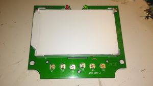
PCB Front
PCB Front

The front of the PCB has the ENIG contacts of the front panel buttons, and the LCD backlight assembly. There’s nothing else under the plastic backlight spreader either.
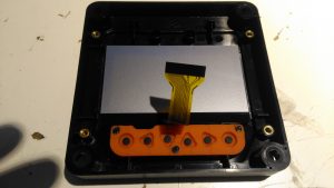
LCD Rear
LCD Rear

The front case holds the LCD module in place with glue, and the rubber buttons are placed underneath, which is heat staked in place.
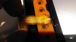
LCD Model
LCD Model

The LCD is a YC1420840CS6 from eCen in China. Couldn’t find much out about this specific LCD.
Posted on 4 Comments

TS100 12-24v Soldering Iron

Handle
Handle

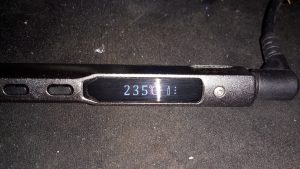
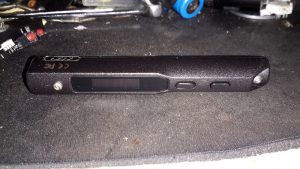
When I ordered the tiny USB soldering iron, I decided a proper iron upgrade would be a good idea. Looking around for something that didn’t require AC mains power turned up the TS100, a Chinese design, that unusually is actually very good! Above is the handle itself, with it’s small OLED display & two operation buttons.
This iron is controlled by a STM32 ARM microcontroller, the firmware & schematics are completely open-source.

DC Input Jack / USB Port

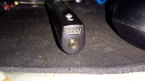
The bottom end of the iron has the main DC input jack, designed with laptop chargers in mind (DC input range from 10v-24v). Above that is the micro USB port for programming.

Heating Element Socket

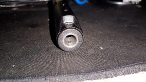
The iron tips slot into the other end, many different tip types & shapes are available. The one supplied was the simple conical tip.

Standby Screen
Standby Screen

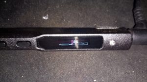
Plugging the iron into some power gets a standby screen – it doesn’t just start heating immediately, for safety.

Heating
Heating

The left hand button starts the heater, which on a 24v input voltage gets to operating temperature well within 10 seconds.

Temperature Stable
Temperature Stable

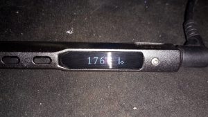
The right hand screen icon changes when the temperature has stabilized. The control PCB has an integrated accelerometer, leaving the iron hot for a few minutes triggers a timeout & it powers down. Once picked up again, the heater instantly restarts.
The operating temperature is adjustable with the pair of buttons, from 100°C to 400°C.

Different Bits
Different Bits

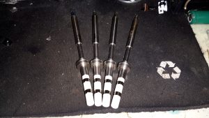
Here’s a selection of bits for the iron. The design is very similar to the Hakko T15 series of irons, but these are a much shorter version. Like the Hakko versions, the actual tips aren’t replaceable, once the bit burns out, the entire assembly is replaced.

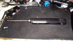
TS100 Soldering Iron

Here’s the iron fully assembled. The entire device is about the same length as just the heating element from a Hakko T15!

Posted on Leave a comment

PCMCIA Ethernet Card

Front
Front

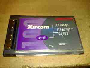
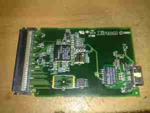
An old Xircom Ethernet card for a laptop. This uses the old 50 pin PCMCIA interface.

Rear
Rear

Rear of the card with the MAC address & card spec details.

PCB
PCB

PCB removed from the outer shield. Xircom ethernet chipset centre. Special socket on the right fits a RJ-45 adaptor lead.

Posted on Leave a comment

Western Digital 160GB 2.5″ HDD

Top Of Drive With Label
Top

This is a Western Digital drive recently removed from my laptop when it died of a severe head crash.
Top of drive can be seen here.

Top Removed From Drive
Top Removed

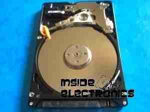
Here the cover has been removed from the drive, showing the platter, head arm & magnet. Yellow piece top left is head parking ramp.

Head Arm of Drive
Head Arm

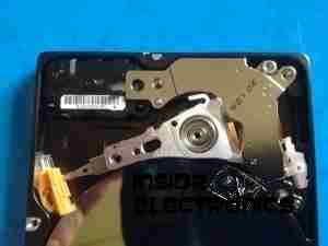
The head assembly of the drive is shown here. The head itself is on the left hand end of the arm in the plastic parking ramp. The other end of the arm holds the voice coil part of the head motor, surrounded by the magnet.

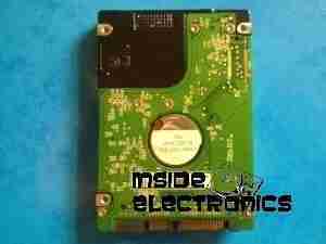
Bottom Of Drive with PCB

Bottom of drive, with controller PCB. SATA interface socket at bottom.

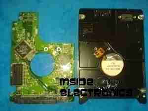
PCB removed from bottom of drive. Spindle motor connections & connections to the head unit can be seen on the bottom of the drive unit.

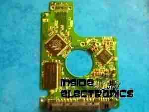
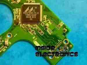
Controller PCB. Supports the cache, interface & motor controller ICs.

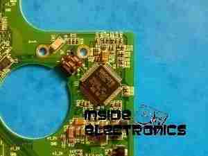
Closeup of the motor driver IC, this controls the speed of the spindle motor precisely to 5,400RPM. Also controls the voice coil motor controlling the position of the head arm on the platters.

Interface IC closeup. This IC receives signals from the head assembly & processes them for transmission to the SATA bus. Also holds drive firmware, controls the Motor driver IC & all other functions of the drive.

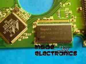
Cache Memory IC.