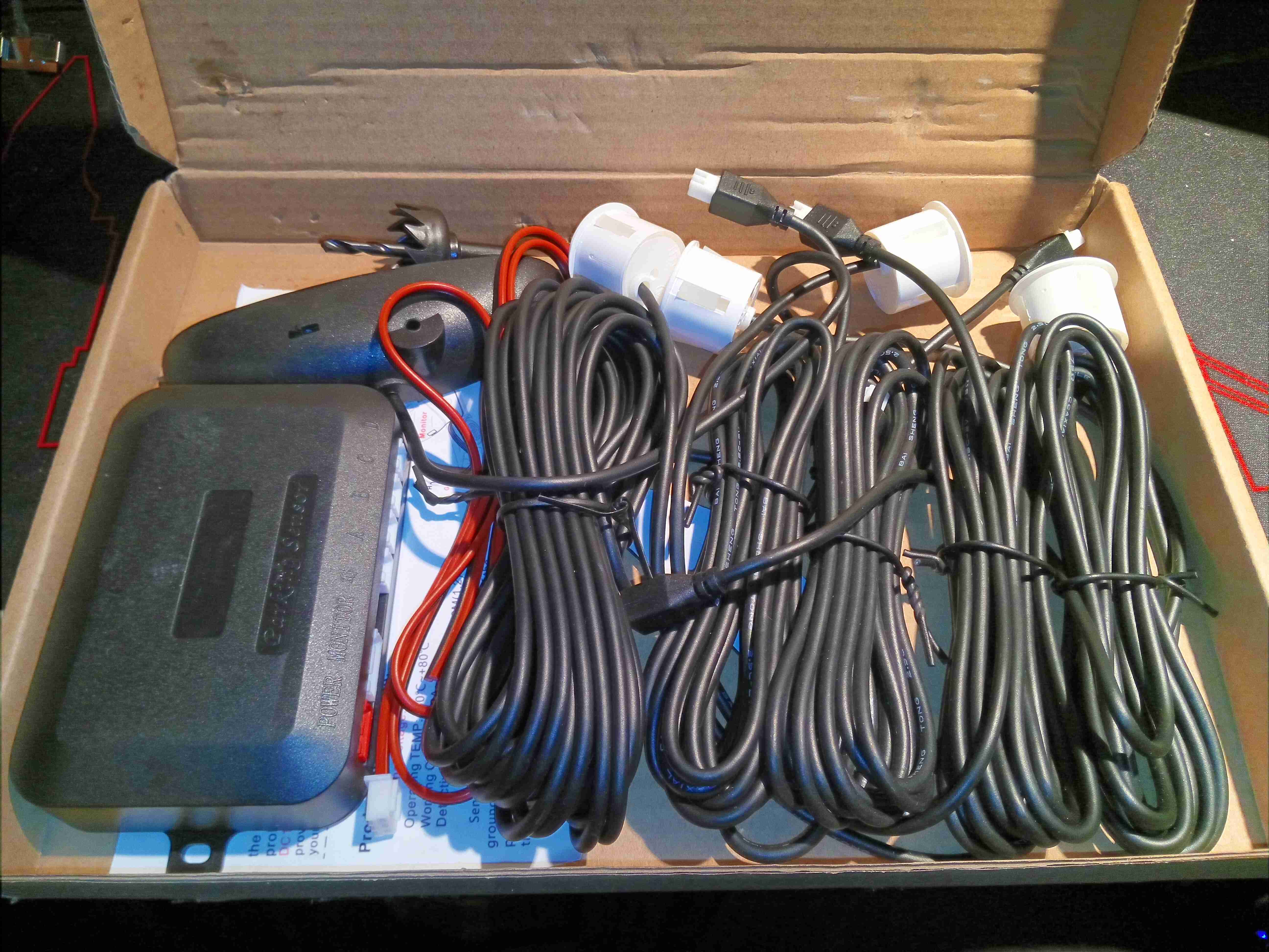
This is a cheap kit from eBay, to retrofit an older car with ultrasonic parking sensors. 4 sensors are included in the kit, along with a hole saw to fit them to the bumper. There’s a small controller module, and a display module that fits onto the dash of the car.
Controller Module
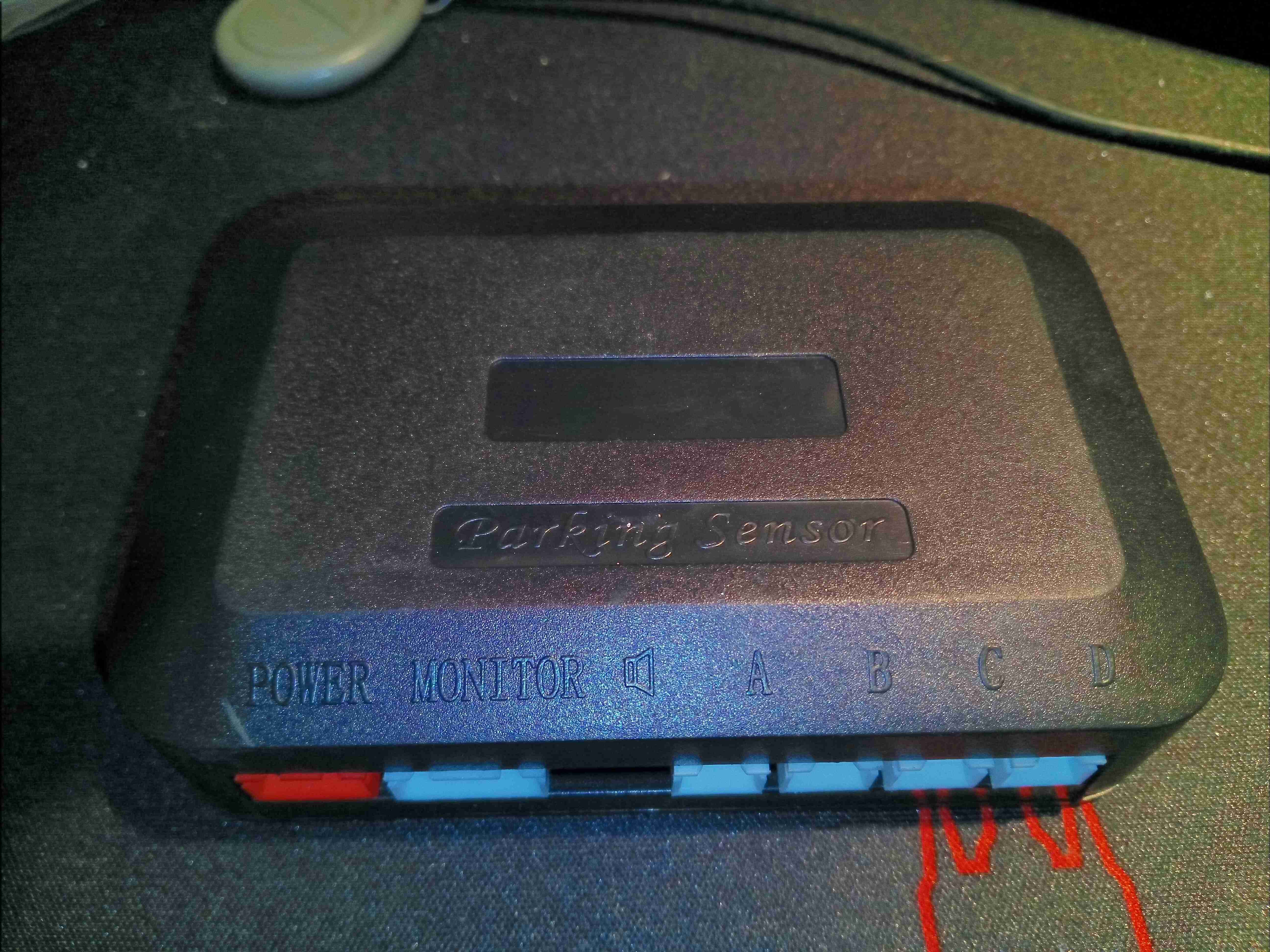
Here’s the controller module, with it’s row of connectors along the front. The unit gets it’s power from the reversing light circuit, via the red connector.
Main Controller PCB
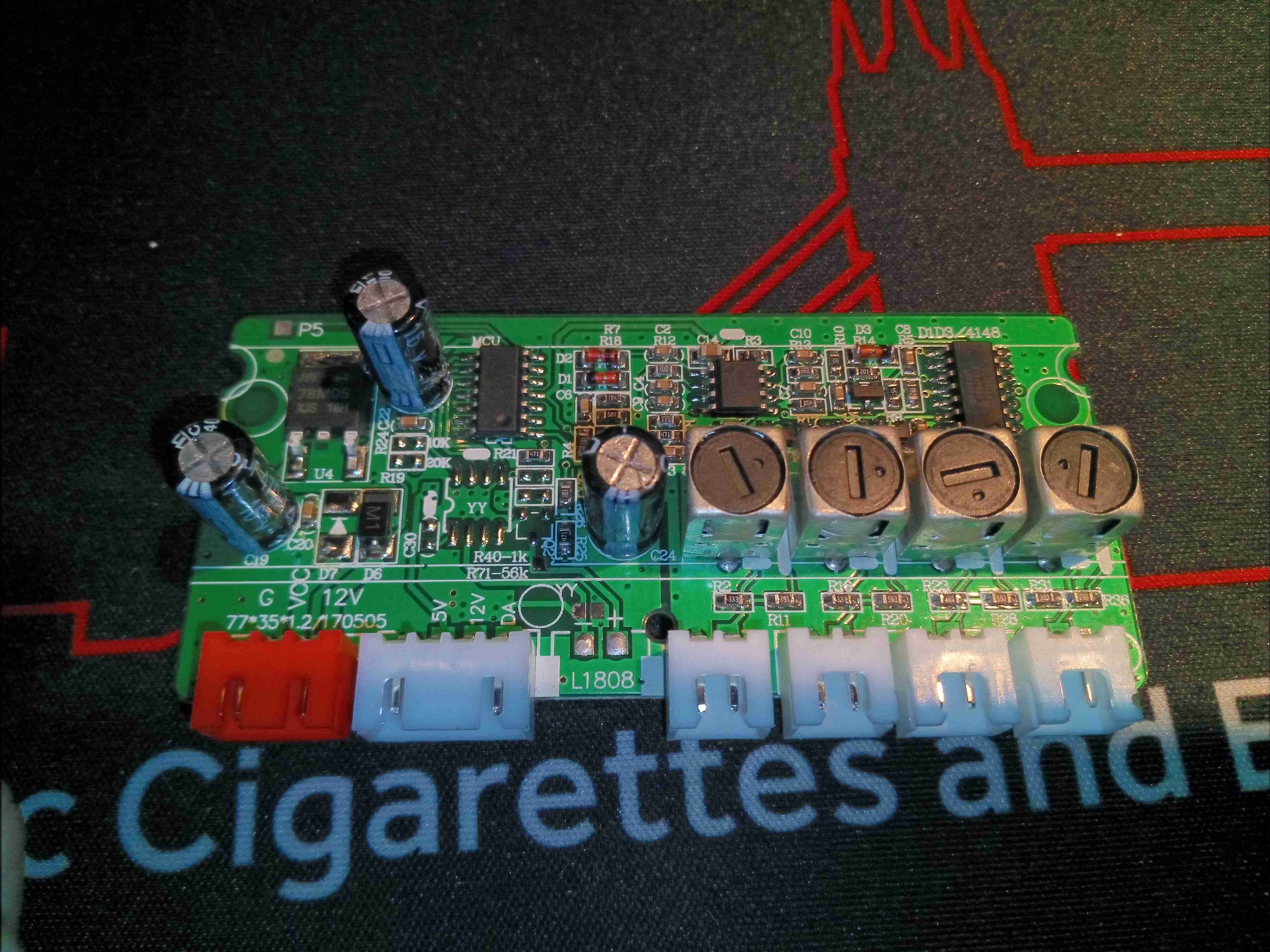
Removing a couple of screws allows the PCB to be removed. There’s quite a bit on this board, including 4 tunable inductors for the ultrasonic transducers. There’s a linear voltage regulator on the left which supplies power to the electronics, and a completely unmarked microcontroller.
Electronics Closeup
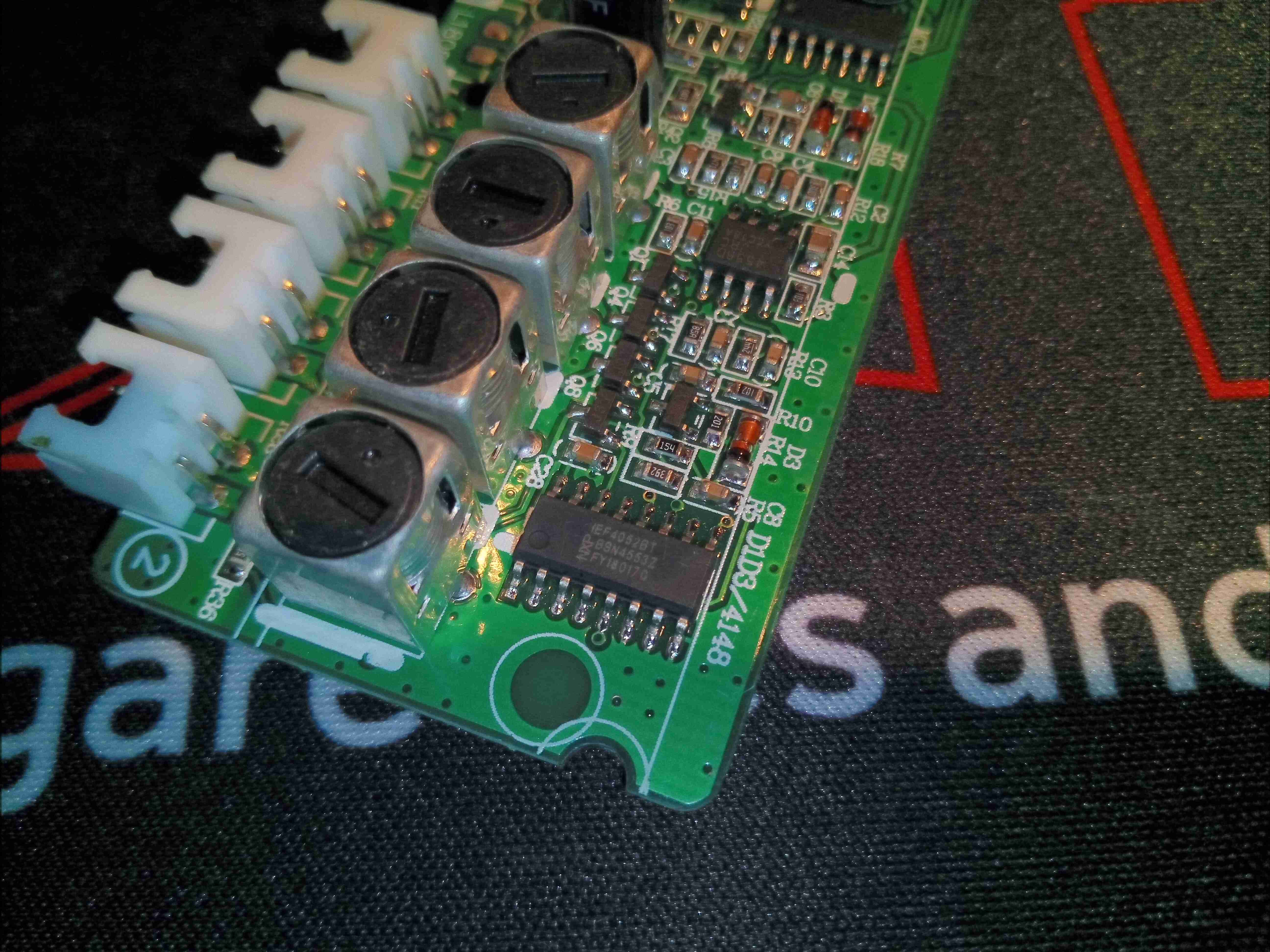
A closer look at the analogue end of the board shows a JRC4558D dual Op-Amp, and an NXP HEF4052B analogue multiplexer. As the microcontroller is unmarked I have no data for that one.
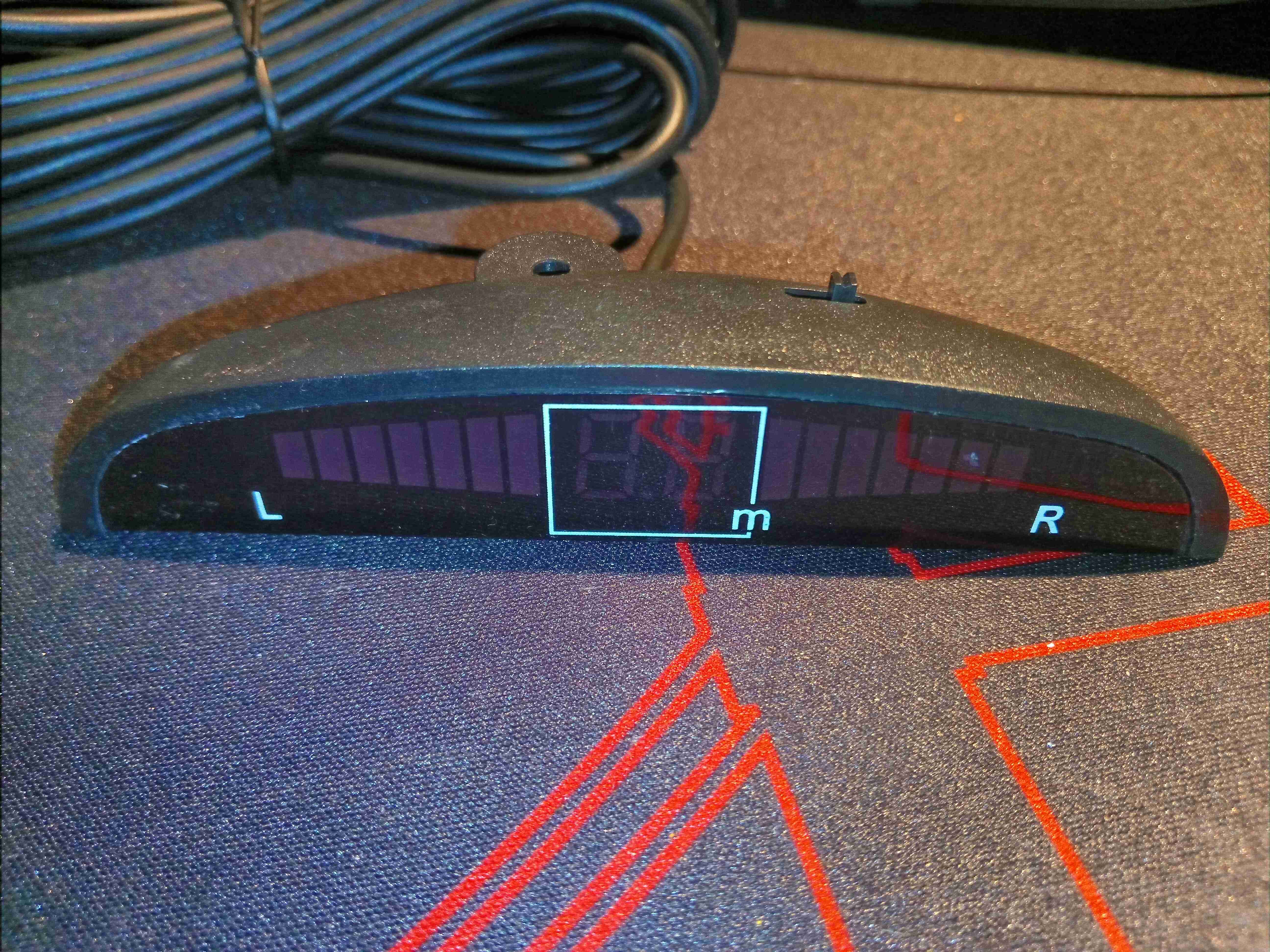
Dash Display
The dash display is housed in another small plastic box, with bargraphs for each side of the car & an overall distance meter.
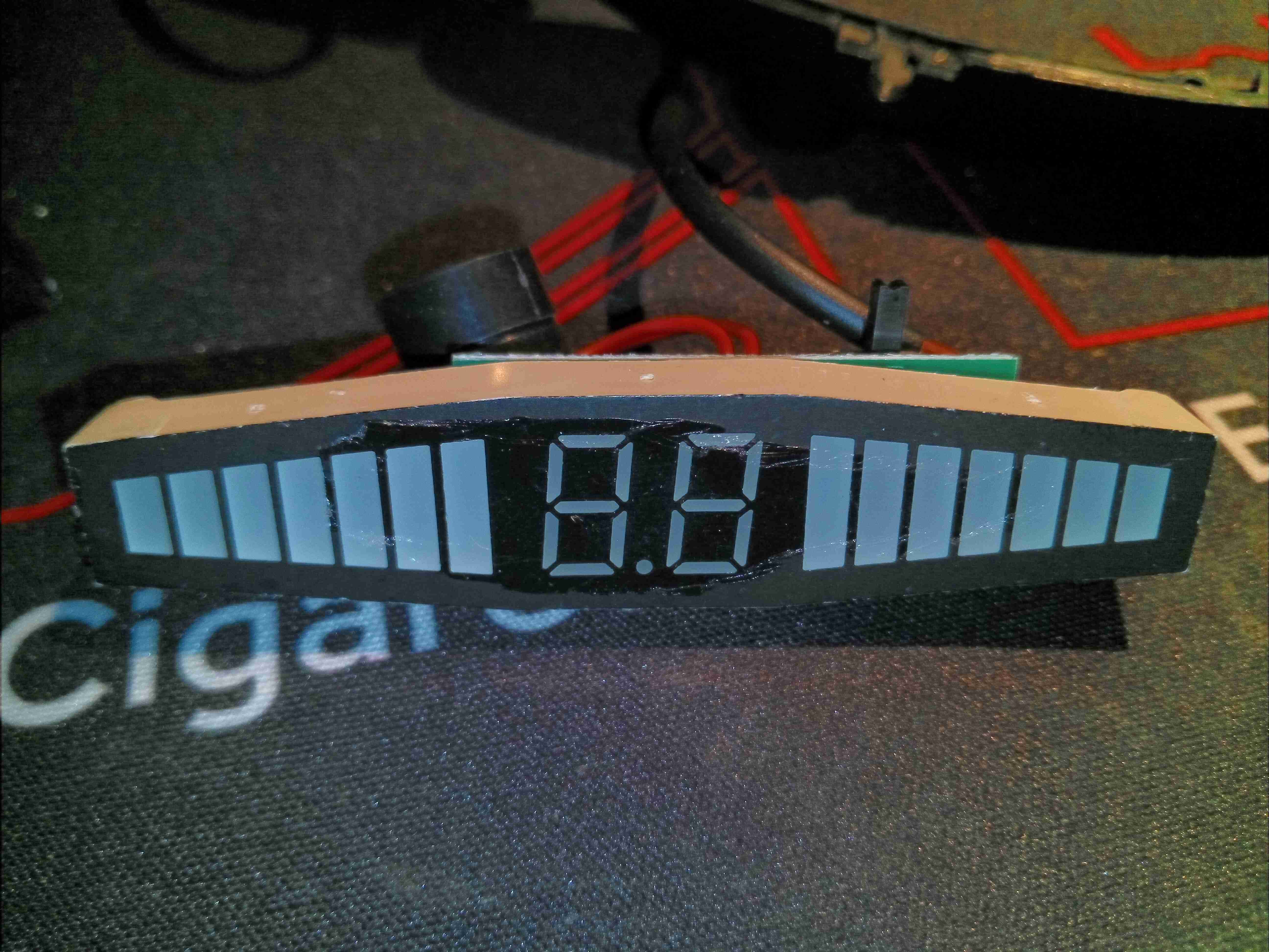
Display Module
Clearly this is a custom module, with the tapered bargraph LEDs on each side & the 7-segment display in the centre. There’s a beeper which works like every factory-fitted unit does, increasing in rate as the distance closes.
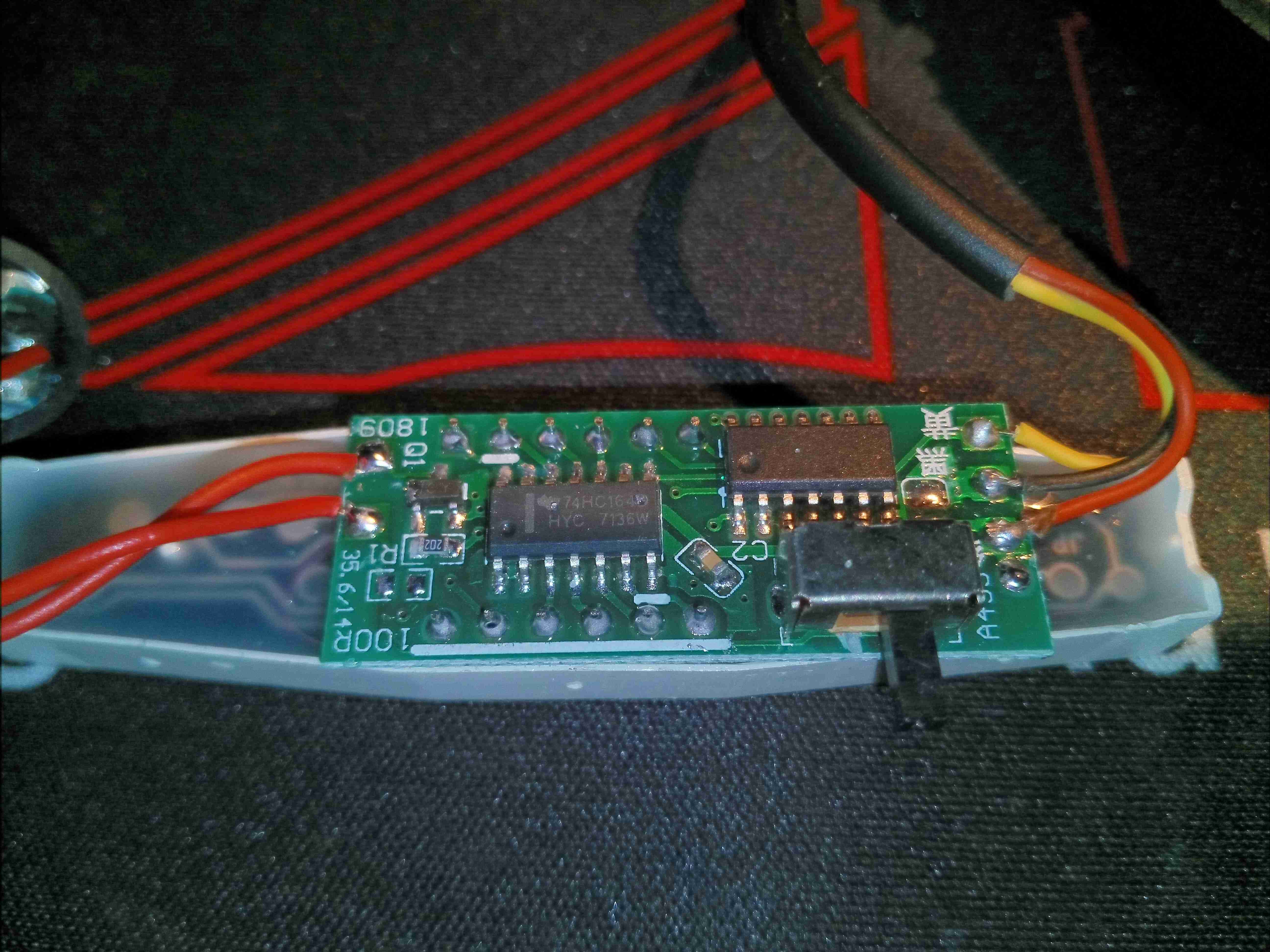
Display PCB
The back of the display module has the driver PCB, with yet another unmarked microcontroller, and a TI 74HC164 serial shift register as a display driver. There’s only 3 wires in the loom from the controller, so some sort of 1-wire protocol must be being used, while I²C is the most likely protocol to be talking to the display driver circuit. There’s also a small switch for muting the beeper.
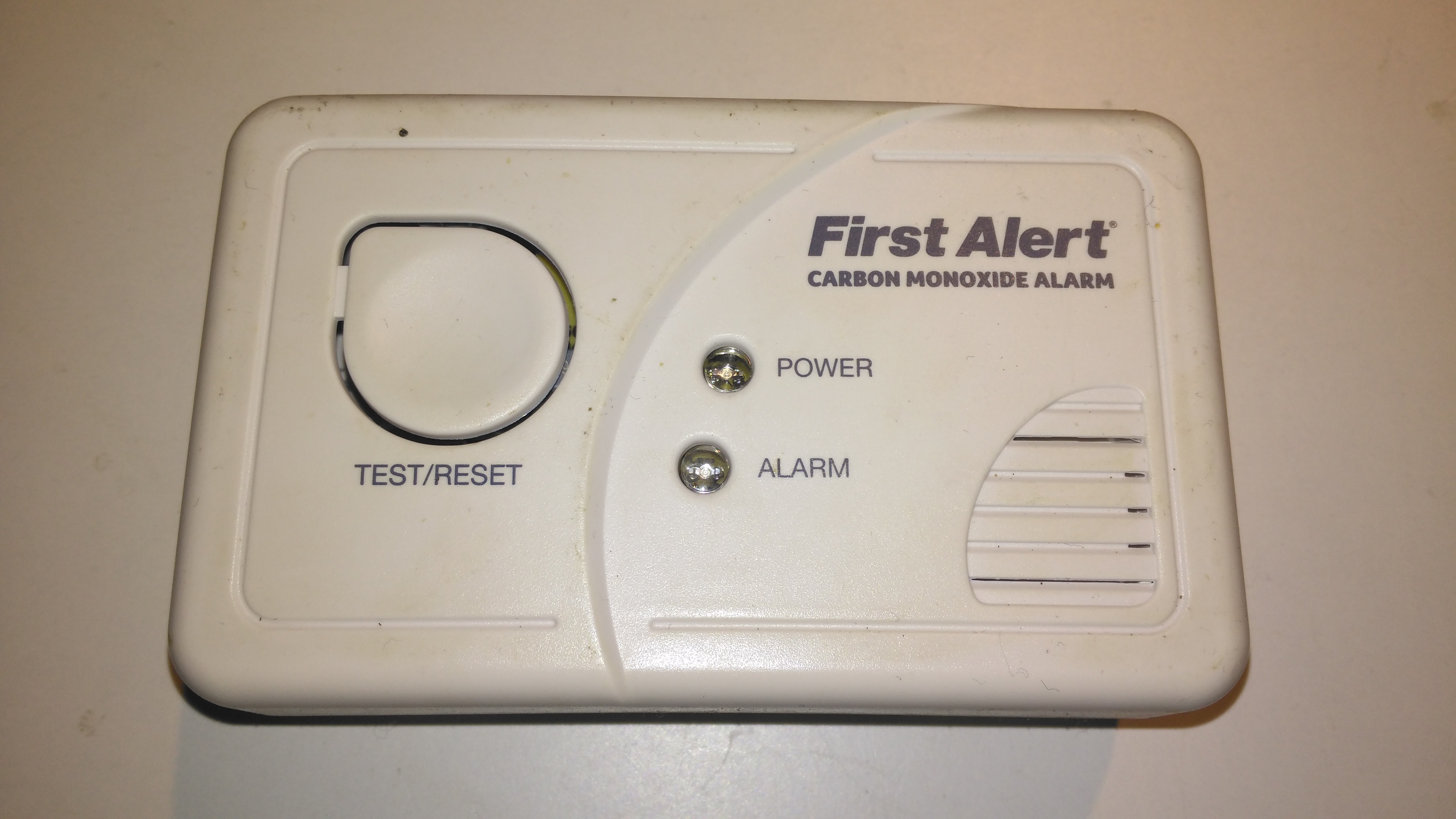
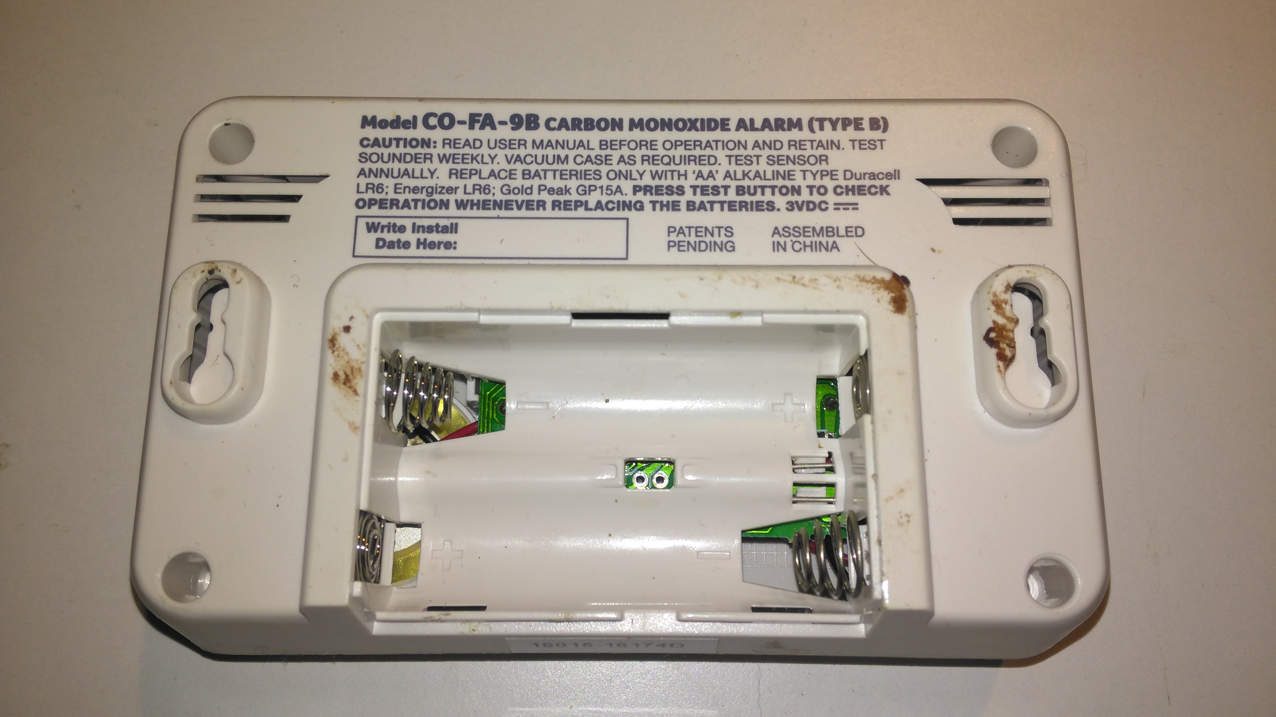
Here’s another domestic CO Alarm, this one a cheaper build than the FireAngel ones usually use, these don’t have a display with the current CO PPM reading, just a couple of LEDs for status & Alarm.
Rear
This alarm also doesn’t have the 10-year lithium cell for power, taking AA cells instead. The alarm does have the usual low battery alert bleeps common with smoke alarms though, so you’ll get a fair reminder to replace them.
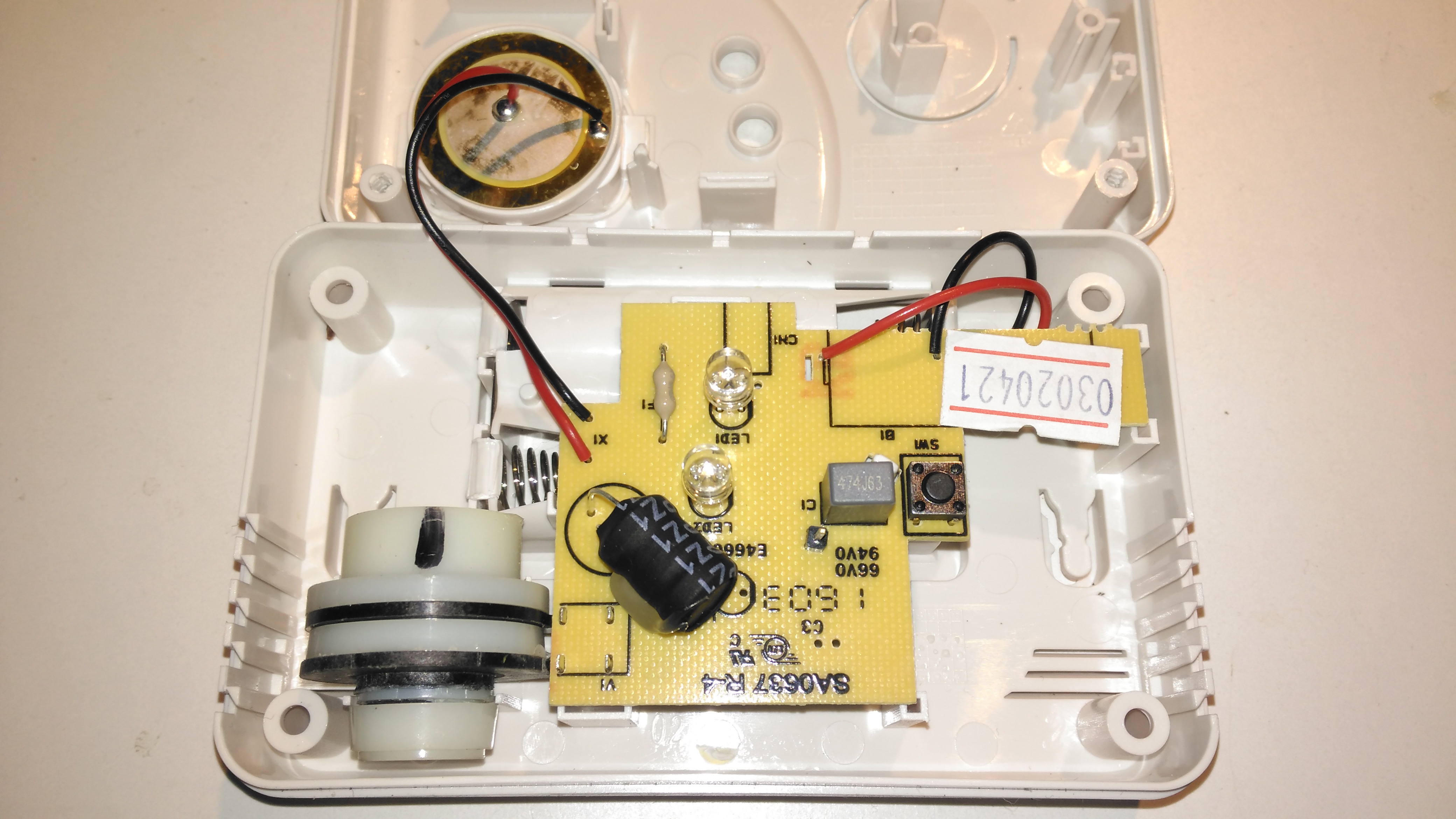
Internals
Not much at all on the inside. The CO sensor cell is the same one as used in the FireAngel alarms, I have never managed to find who manufactures these sensors, or a datasheet for them unfortunately.
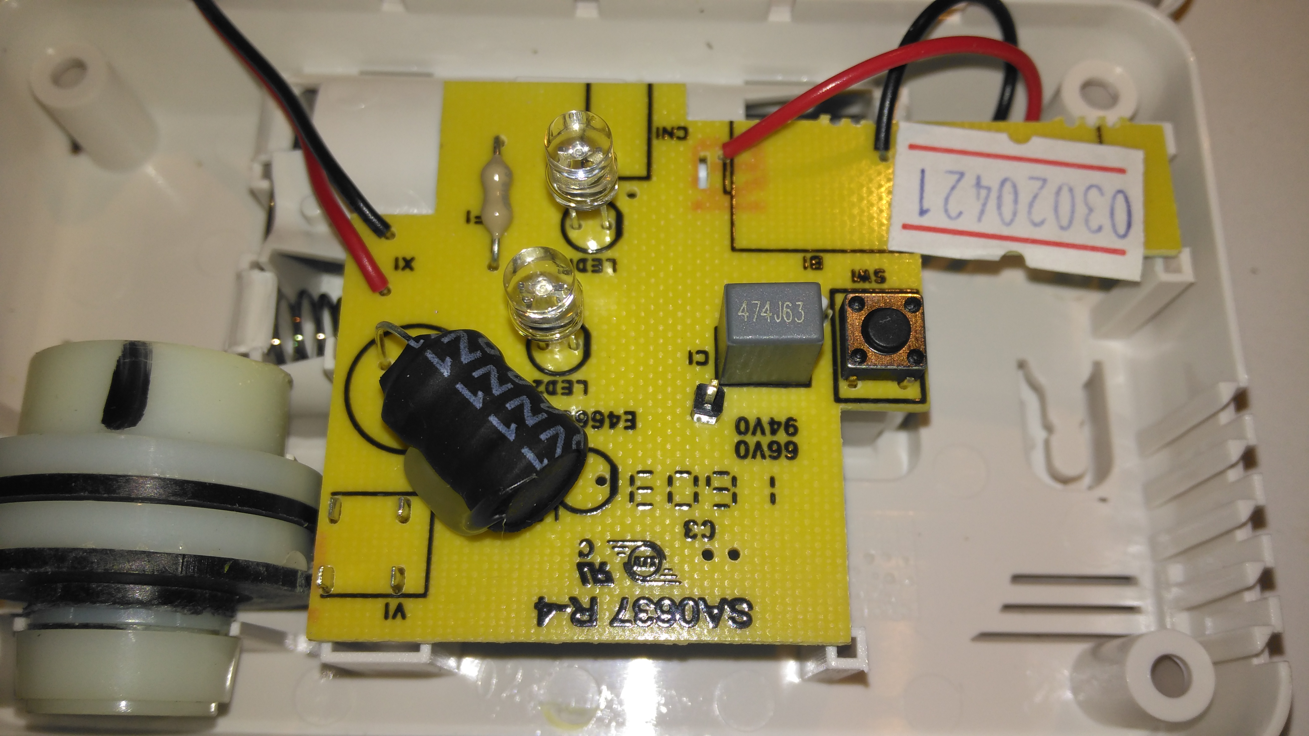
PCB Top
The top of the single sided PCB has the transformer for driving the Piezo sounder, the LEDs & the test button.
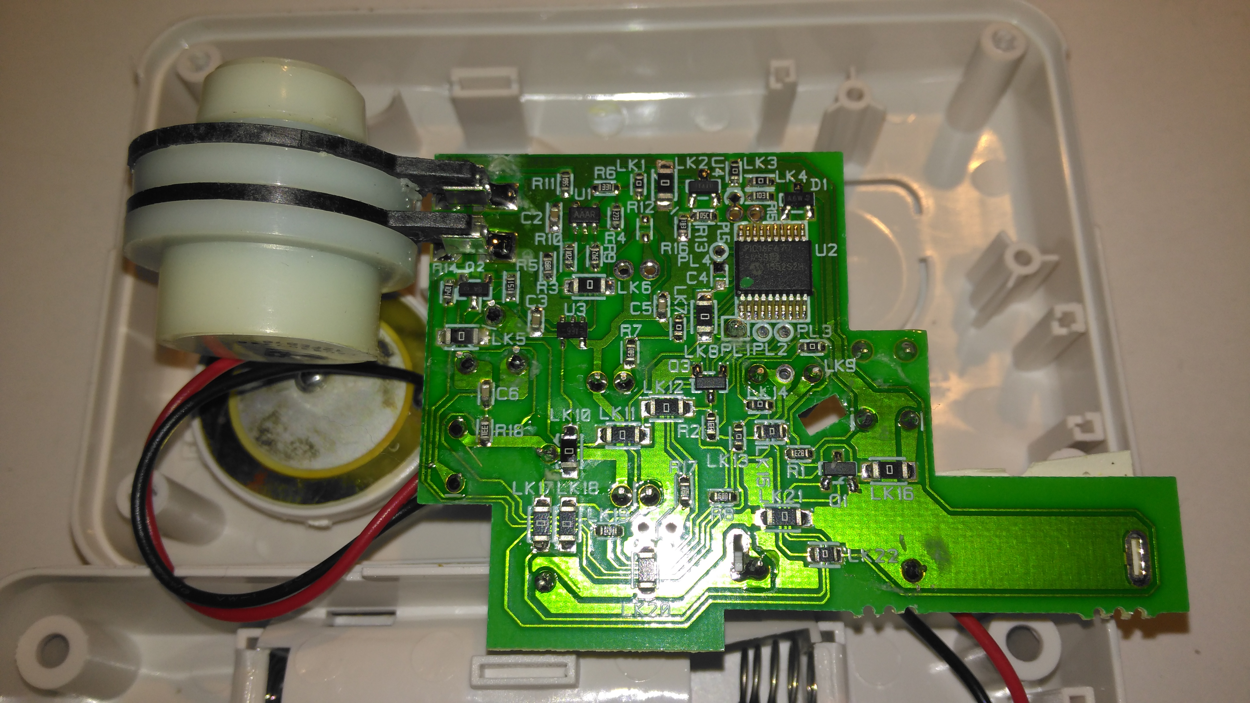
PCB Bottom
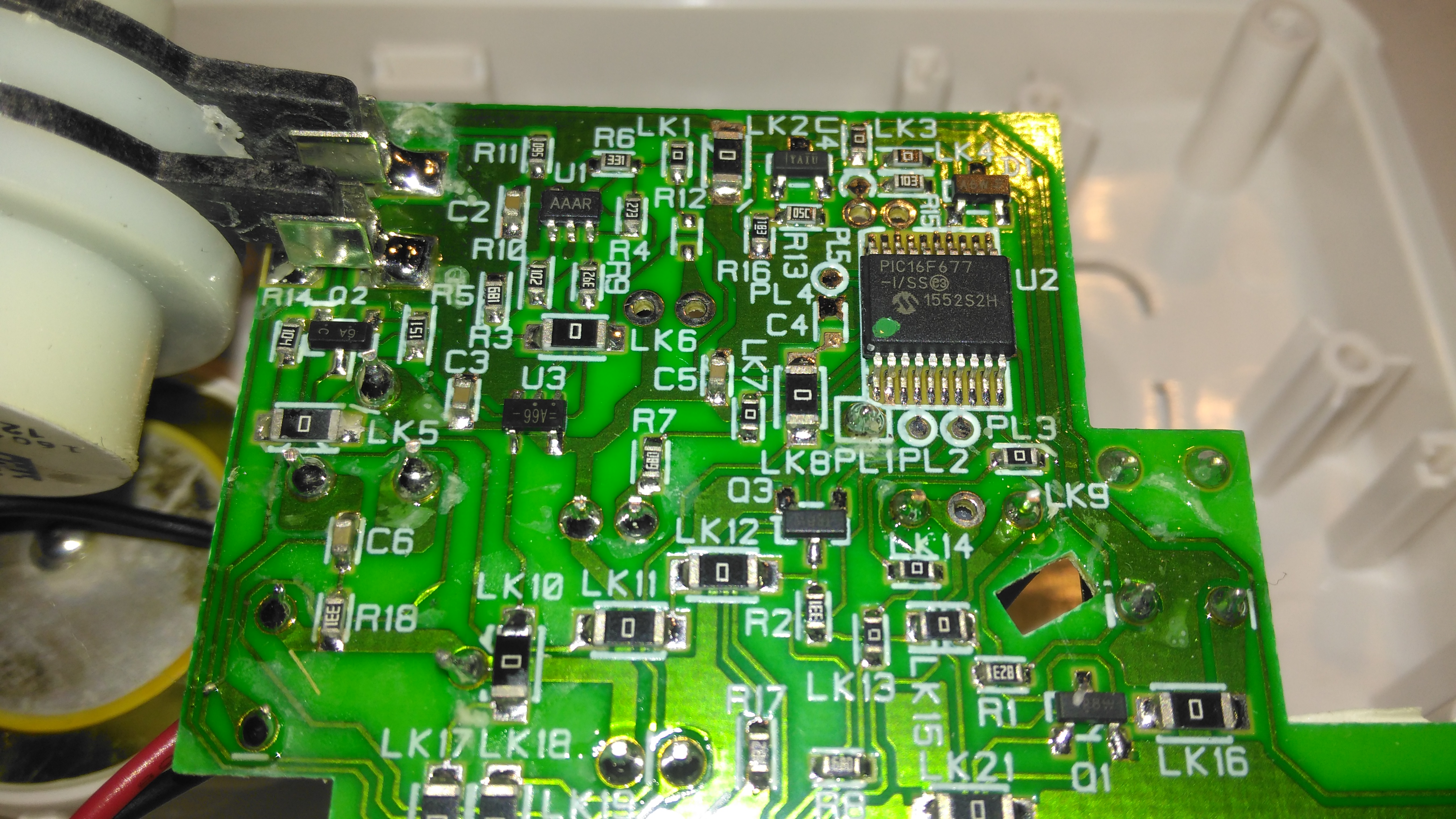
All the magic happens on the bottom of the PCB. The controlling microcontroller is on the top right, with the sensor front end on the top left.
Circuitry Closeup
The microcontroller used here is a Microchip PIC16F677. I’ve not managed to find datasheets for the front end components, but these will just be a low-noise op-amp & it’s ancillaries. There will also be a reference voltage regulator. The terminals on these sensors are made of conductive plastic, probably loaded with carbon.
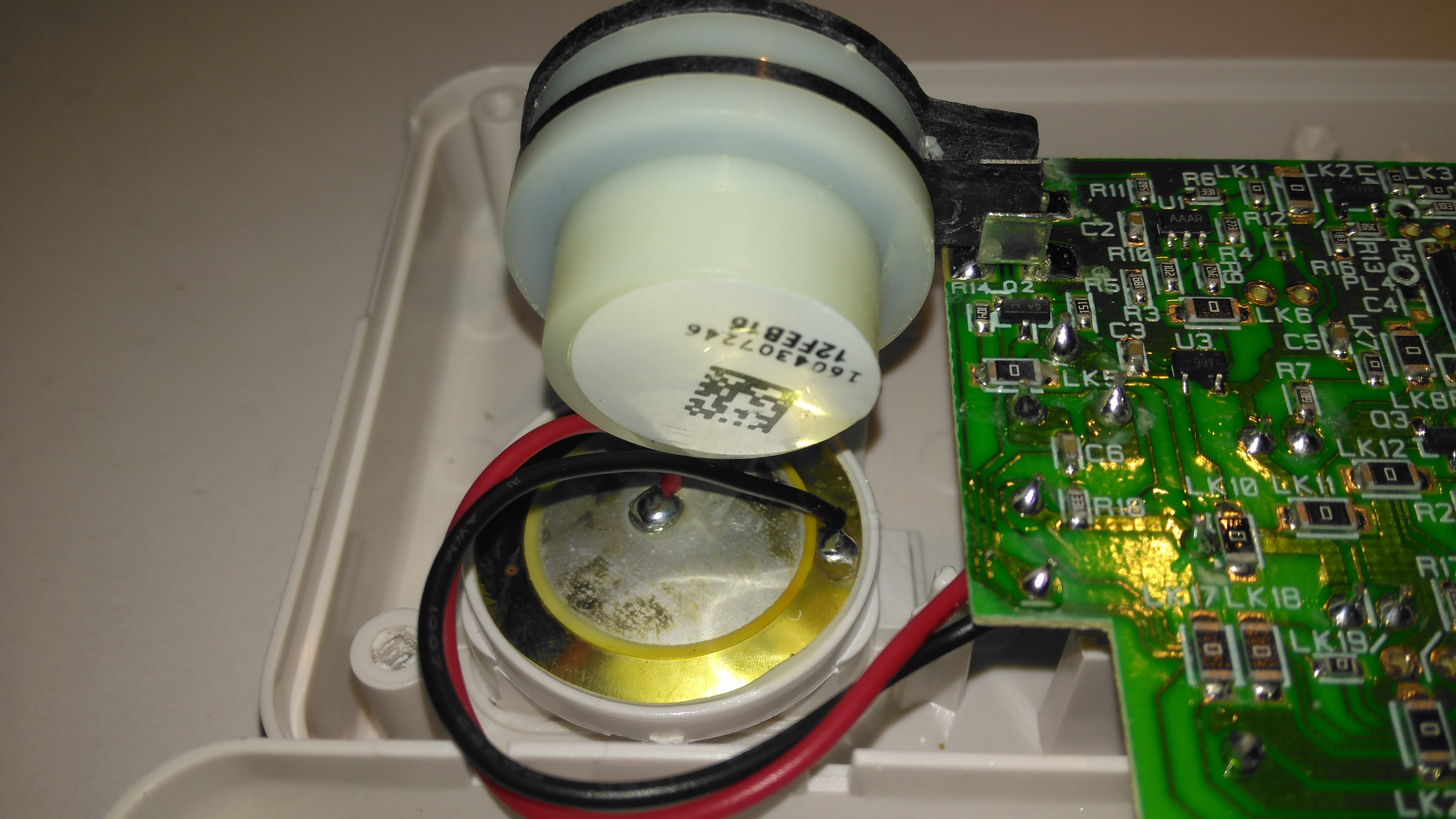
Sensor Cell & Piezo Disc
The expiry date is handily on a label on the back of the sensor, the Piezo sounder is just underneath in it’s sound chamber.
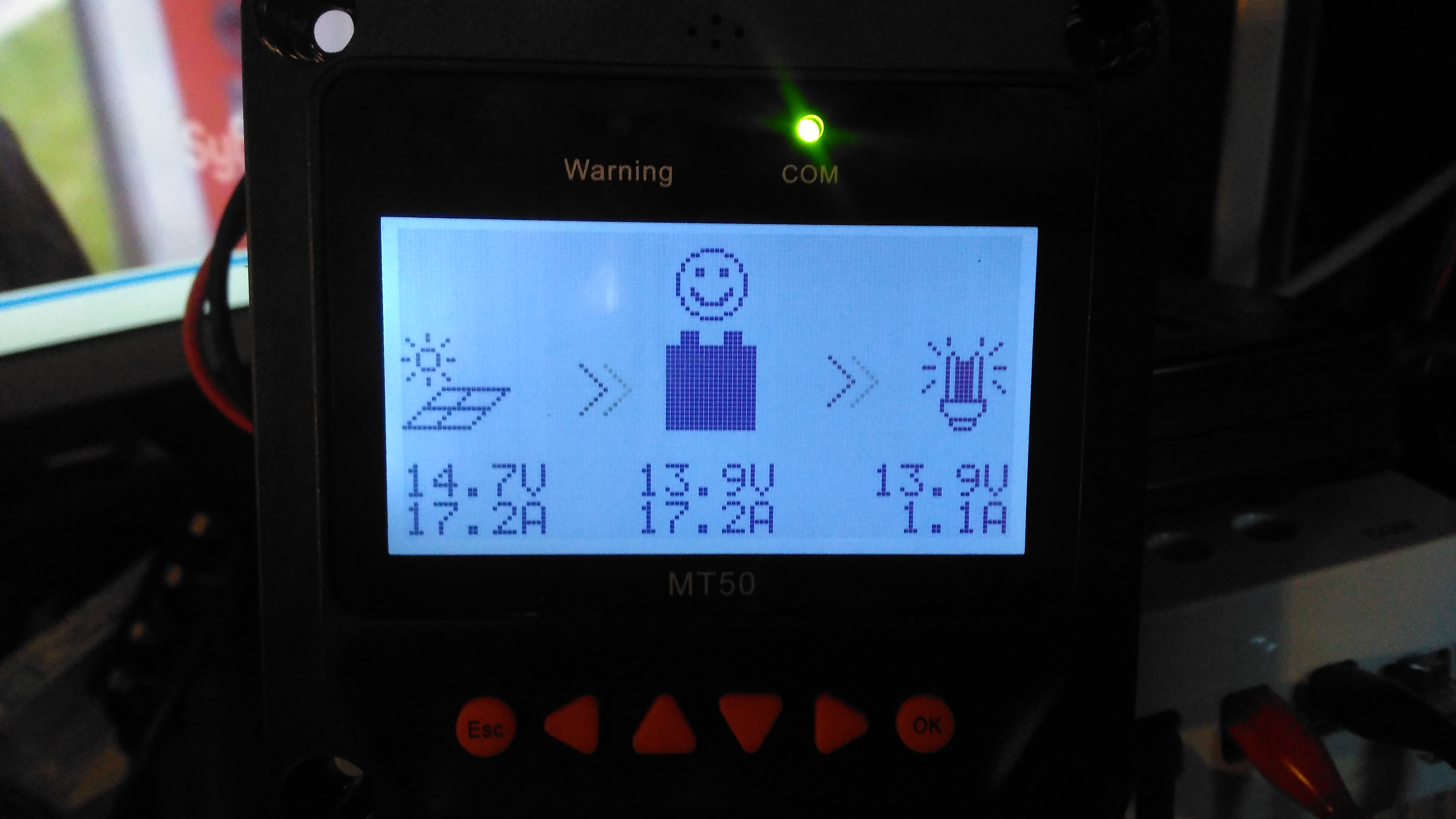
Here’s the MT50 controller from EpEver, that interfaces with it’s Tracer MPPT solar charge controllers, and gives access to more programming options on the charge controllers, without the need for a laptop. The display is a large dot-matrix unit, with built in backlight. Above is the display on the default page, showing power information for the entire system.
PCB Rear
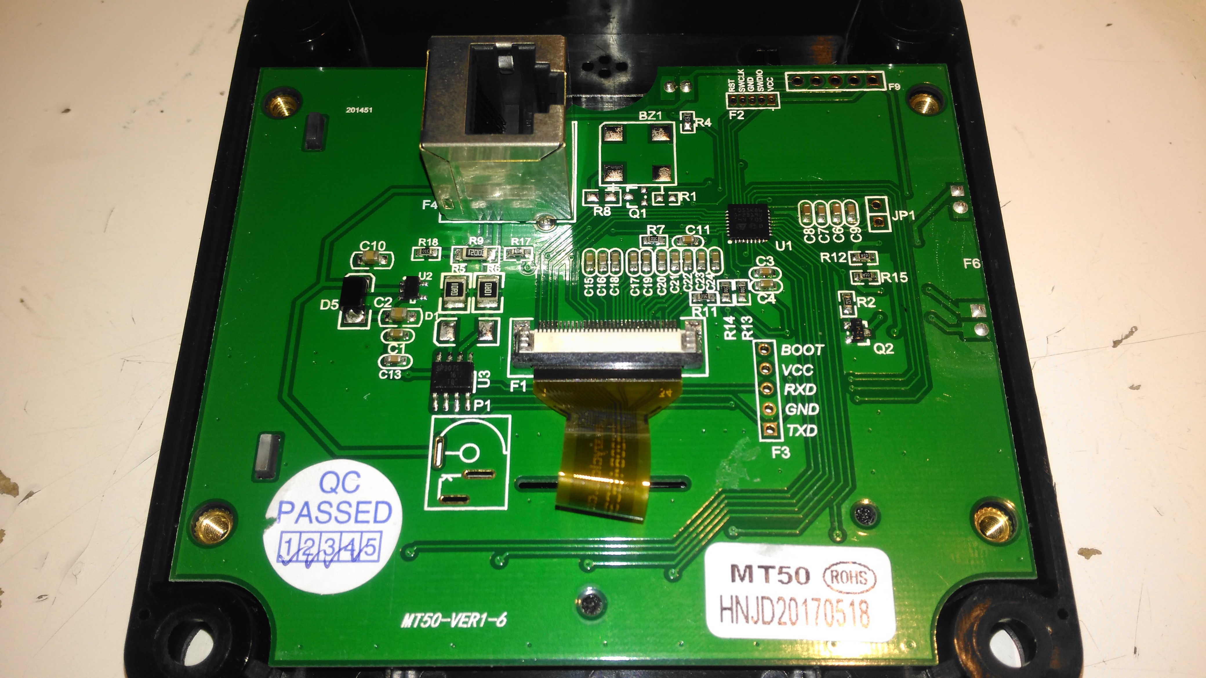
The rear plastic cover is held in place by 4 machine screws, which thread into brass inserts in the plastic frame – nice high quality touch on the design here, no cheap self tapping plastic screws. Both power & data arrive via an Ethernet cable, but the communication here is RS-485, and not compatible with Ethernet! The PCB is pretty sparse, with comms & power on the left, LCD connection in the centre, and the microcontroller on the right.
RS-485 Transceiver
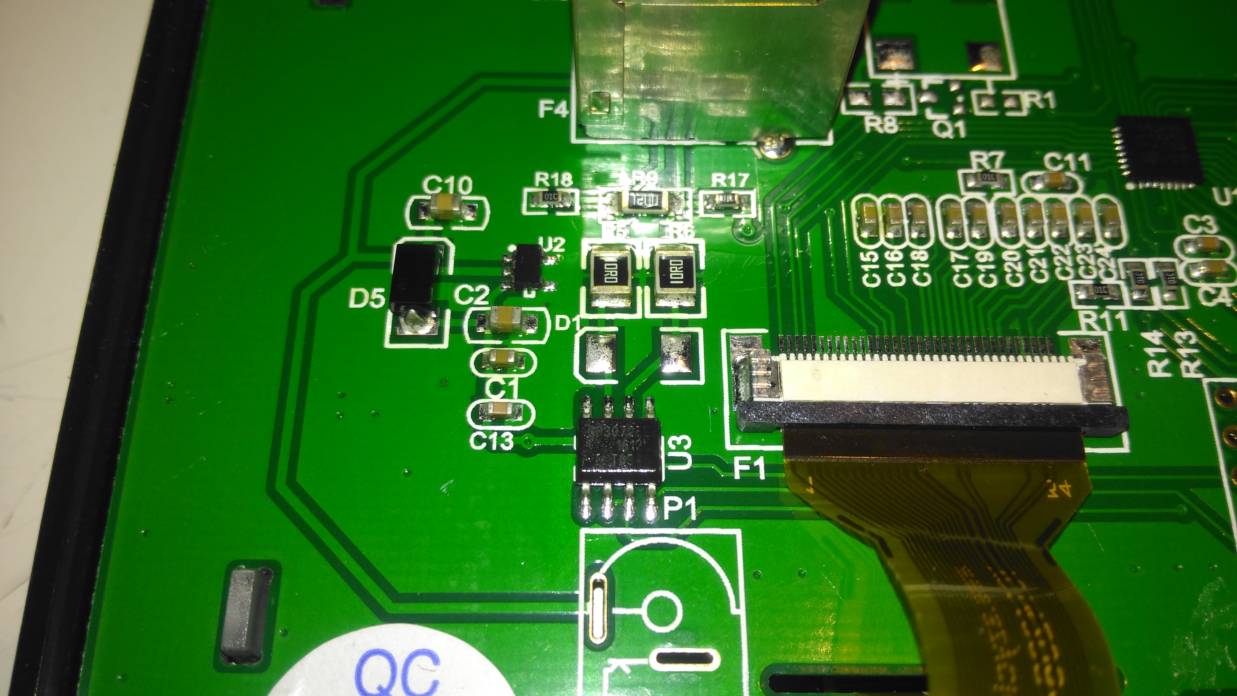
On the left of the board is the RS0485 transceiver, and a small voltage regulator. There’s also a spot for a DC barrel jack, which isn’t included in this model for local power supply.
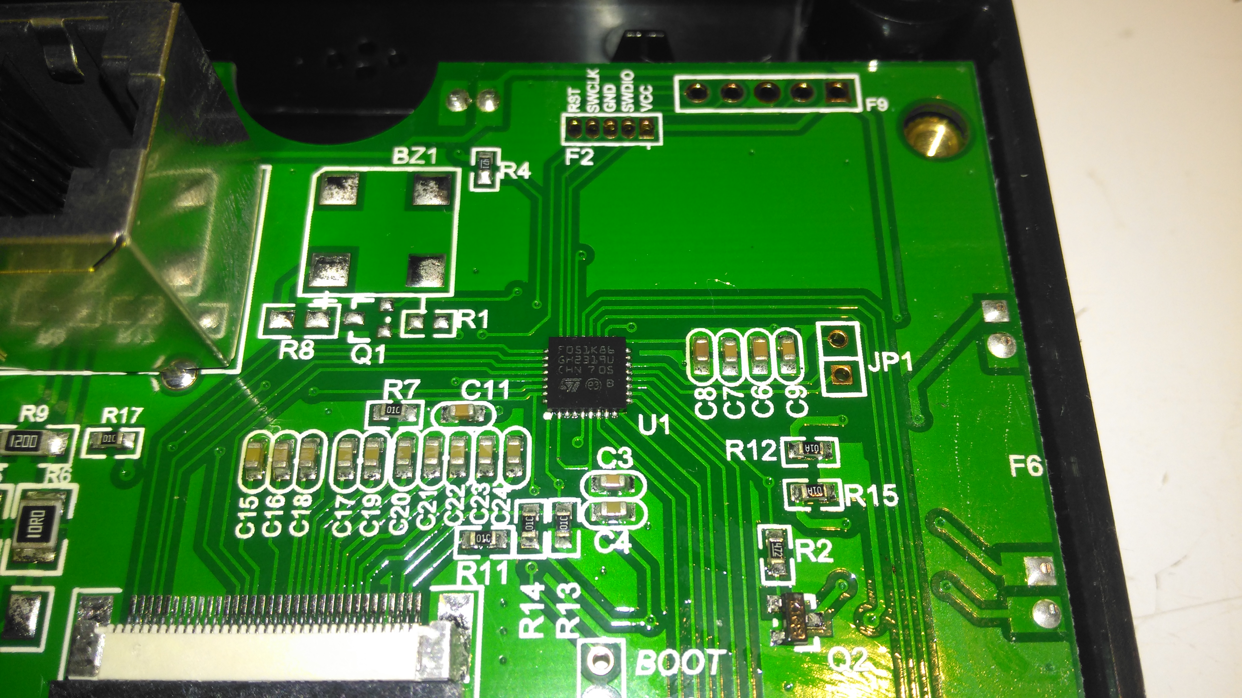
STM32 Microcontroller
The other side of the board holds the main microcontroller which communicates with the charge controller. This is a STM32F051K8 from ST Microelectronics. With a 48MHz ARM Cortex M0 core, and up to 64K of flash, this is a pretty powerful MCU that has very little to do in this application.
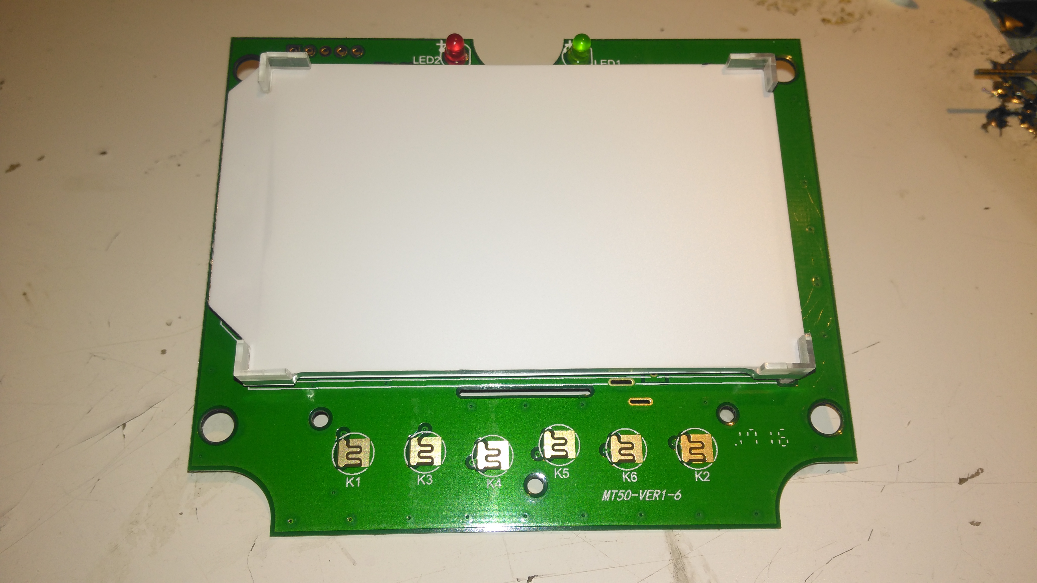
PCB Front
The front of the PCB has the ENIG contacts of the front panel buttons, and the LCD backlight assembly. There’s nothing else under the plastic backlight spreader either.
LCD Rear
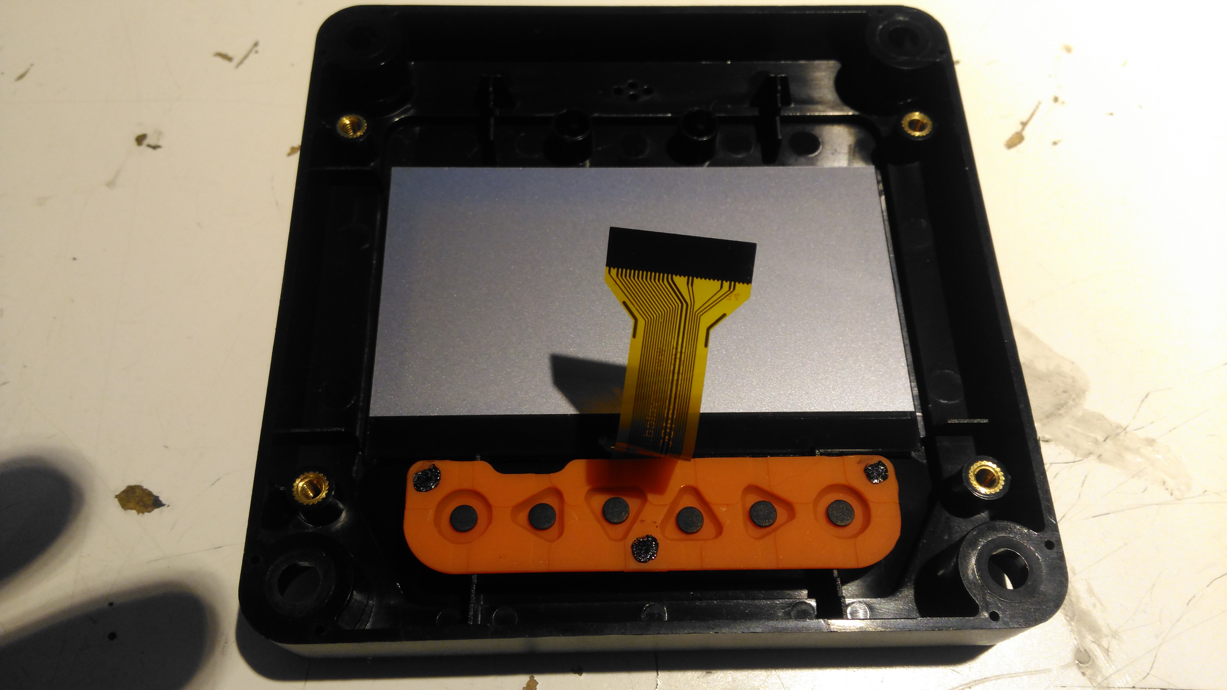
The front case holds the LCD module in place with glue, and the rubber buttons are placed underneath, which is heat staked in place.
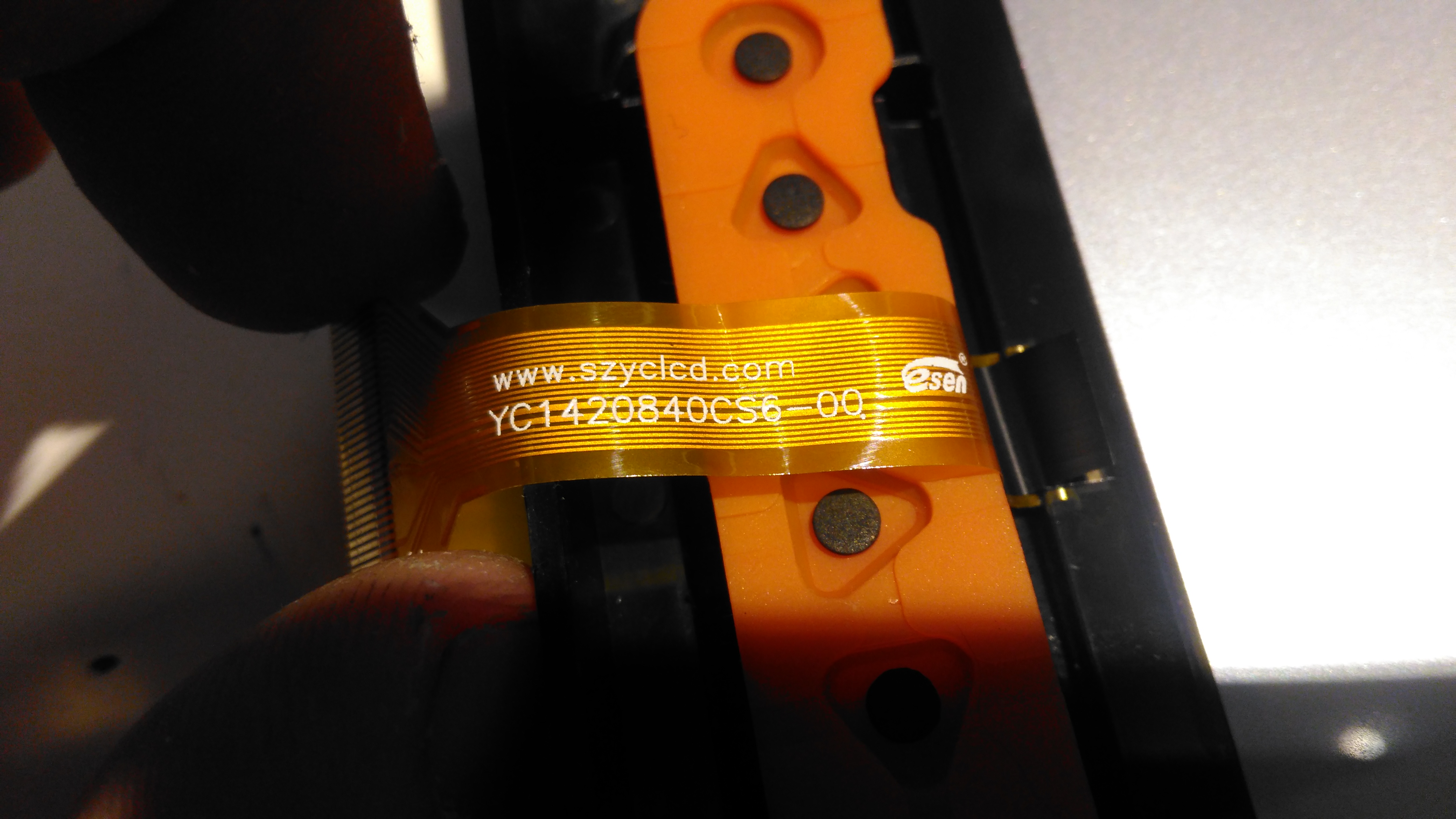
LCD Model
The LCD is a YC1420840CS6 from eCen in China. Couldn’t find much out about this specific LCD.
This is a chip aimed at the automotive market – this is a low power voltage regulator for supplying power to microcontrollers, for instance in a CD player.
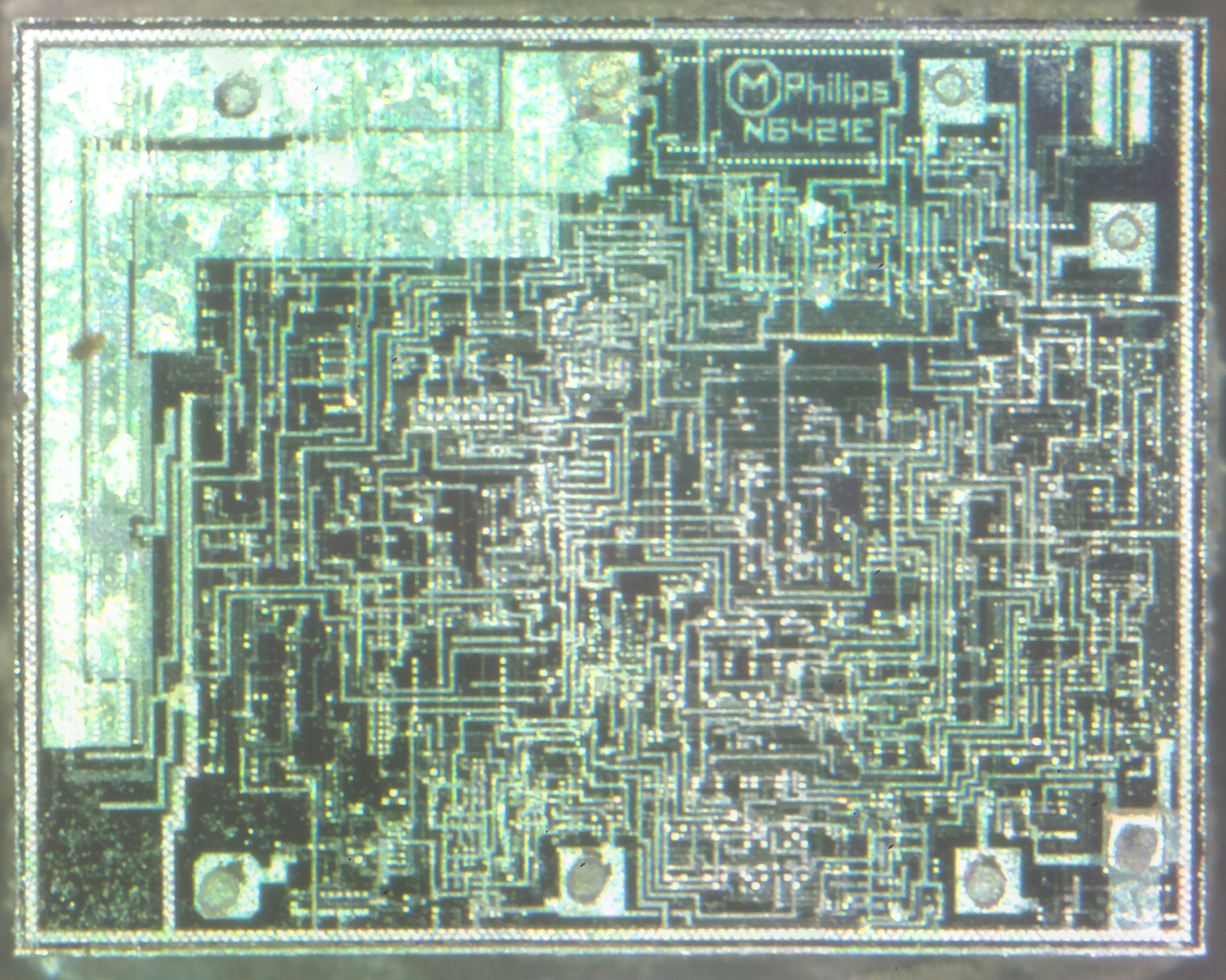
TDA3606 Die
The TDA3606 is a voltage regulator intended to supply a microprocessor (e.g. in car radio applications). Because of low voltage operation of the application, a low-voltage drop regulator is used in the TDA3606. This regulator will switch on when the supply voltage exceeds 7.5 V for the first time and will switch off again when the output voltage of the regulator drops below 2.4 V. When the regulator is switched on, the RES1 and RES2 outputs (RES2 can only be HIGH when RES1 is HIGH) will go HIGH after a fixed delay time (fixed by an external delay capacitor) to generate a reset to the microprocessor. RES1 will go HIGH by an internal pull-up resistor of 4.7 kΩ, and is used to initialize the microprocessor. RES2 is used to indicate that the regulator output voltage is within its voltage range. This start-up feature is built-in to secure a smooth start-up of the microprocessor at first connection, without uncontrolled switching of the regulator during the start-up sequence. All output pins are fully protected. The regulator is protected against load dump and short-circuit (foldback
current protection). Interfacing with the microprocessor can be accomplished by means of a battery Schmitt-trigger and output buffer (simple full/semi on/off logic applications). The battery output will go HIGH when the battery input voltage exceeds the HIGH threshold level.
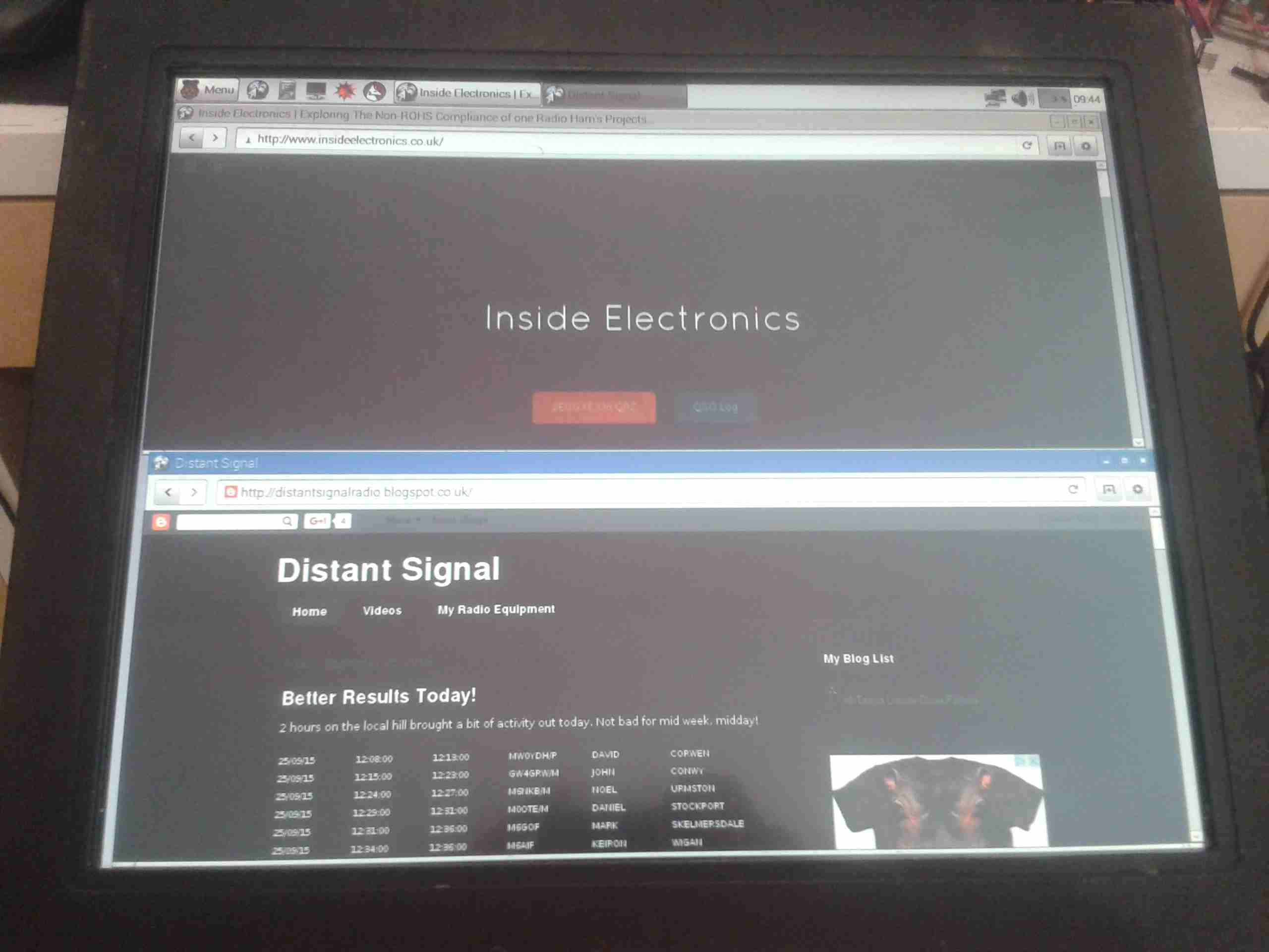
A while back I posted about a 3M Touch Systems industrial monitor that I’d been given. I had previously paired it with a Raspberry Pi Model B+, but for general desktop use it was just a little on the slow side.
Since the release of the Raspberry Pi 2, with it’s 4-core ARM Cortex CPU, things are much improved, so I figured I’d post an update with the latest on the system.
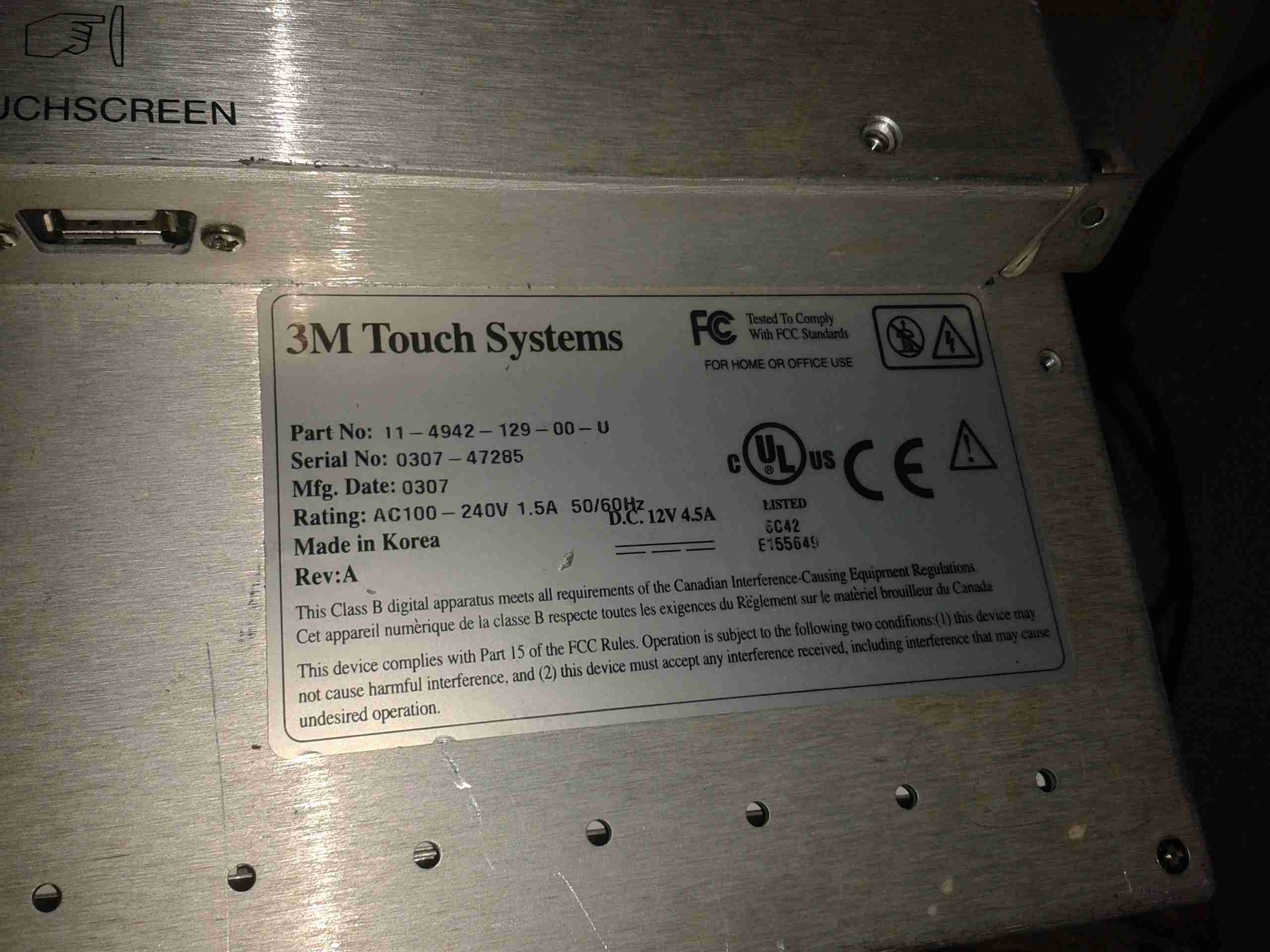
The monitor I’ve used is a commercial one, used in such things as POS terminals, service kiosks, etc. It’s a fairly old unit, but it’s built like a tank.
3M Panel
It’s built around a Samsung LTM170EI-A01 System-On-Panel, these are unusual in that all the control electronics & backlighting are built into the panel itself, instead of requiring an external converter board to take VGA to the required LVDS that LCD panels use for their interface.
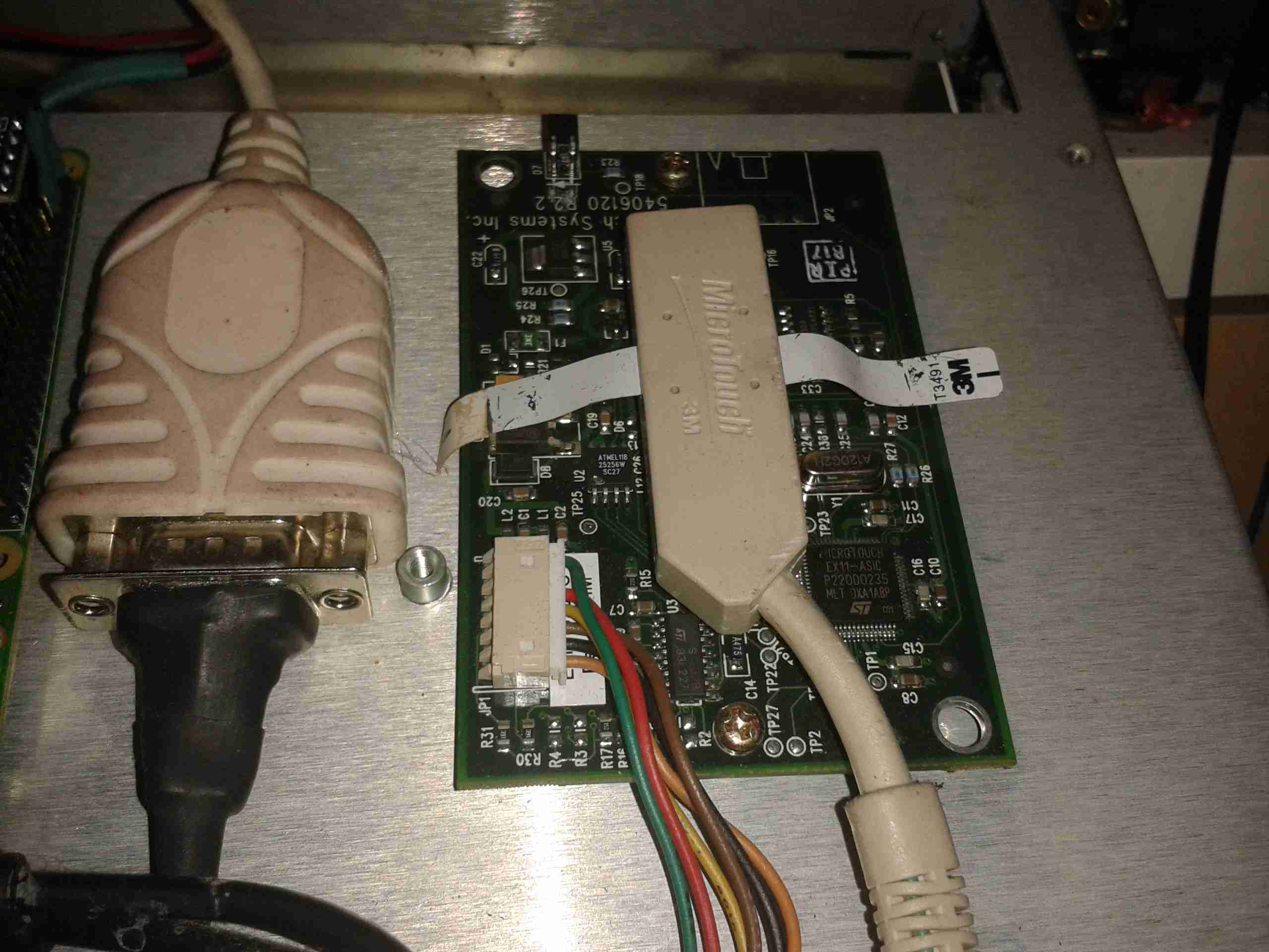
The touch section is a 3M Microtouch EXII series controller, with a surface capacitive touch overlay.
Touch Controller
Above is the touch controller PCB, with it’s USB-Serial converter to interface with the Pi.
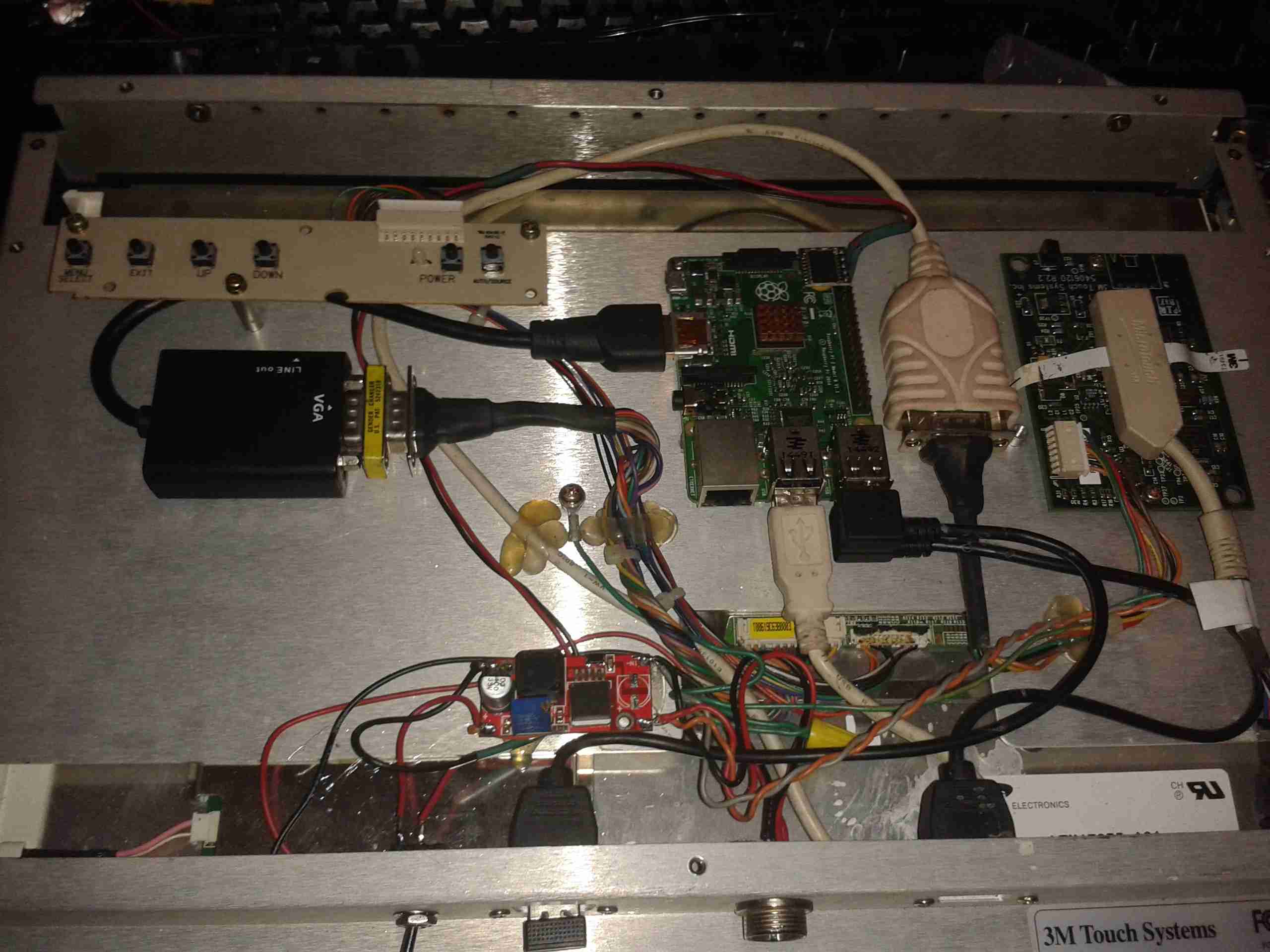
As there is much spare space inside the back of this monitor, I have mounted the Pi on a couple of spare screw posts, fitted USB ports where the original VGA & Serial connectors were in the casing, and added voltage regulation to provide the Pi with it’s required 5v.
Overview
Here’s the entire back of the panel, the Pi in the middle interfaces with a HDMI-VGA adaptor for the monitor, and the serial adaptor on the right for the touch. A small voltage regulator at the bottom of the unit is providing the 5v rail. There’s a switch at the bottom next to one of the USB ports to control power to the Pi itself. The panel won’t detect the resolution properly if they’re both powered on at the same time.
At 13.8v, the device pulls about 2A from the supply, which seems to be typical for a CCFL backlighted LCD.
Now the Raspberry Pi 2 has been released, it’s much more responsive for desktop applications, especially with a slight overclock.
Shameless Plug
A full disk image enabled for Desktop & 3M touch monitors is available below for others that have similar panels. This image only works for the Pi 2!
Recently I decommissioned some networking equipment, and discovered the power supplies in some switches were single rail 12v types, with a rather high power rating. I figured these would be very good for powering my Ham radio gear.
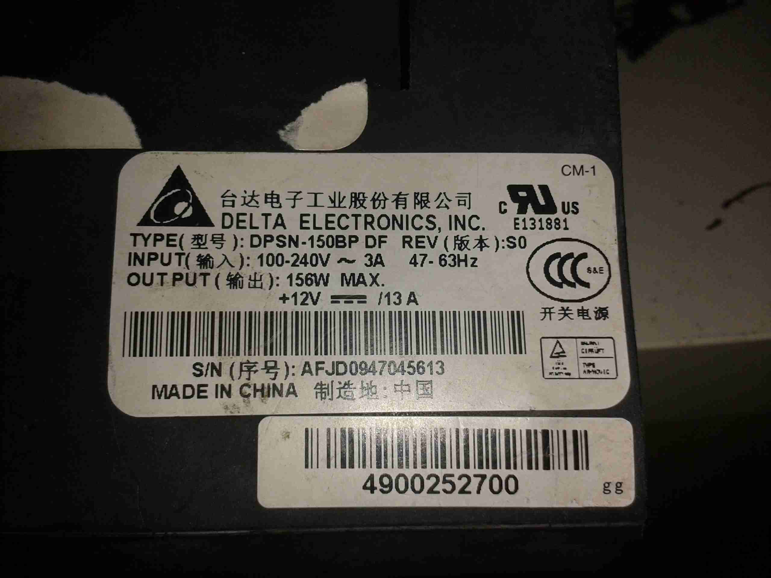
They’re high quality Delta Electronics DPSN-150BP units, rated at a maximum power output of 156W.
Label
These supplies have an adjustment pot for the output voltage regulation, but unfortunately it just didn’t have quite enough range to get from 12.0v to 13.8v. The highest they would go was ~13.04v.
After taking a look at the regulator circuit, I discovered I could further adjust the output voltage by changing a single resistor to a slightly lower value.
Firstly though, a little background on how switched mode power supplies operate & regulate their output voltage.
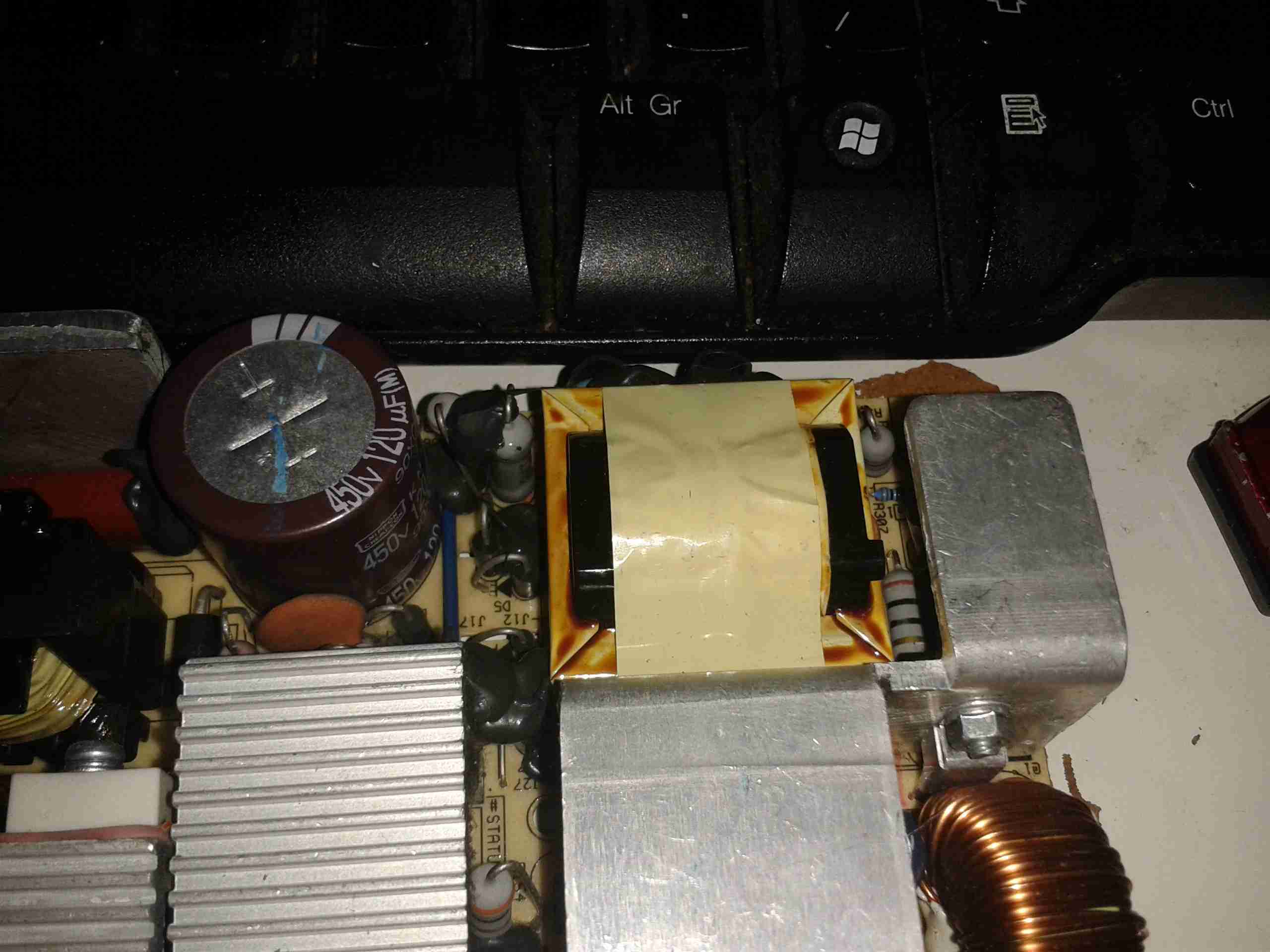
SMPS
Here’s the supply. It’s mostly heatsink, to cool the large power switching transistors.
The first thing a SMPS does, is to rectify the incoming mains AC with a bridge rectifier. This is then smoothed by a large electrolytic capacitor, to provide a main DC rail of +340v DC (when on a 240v AC supply).
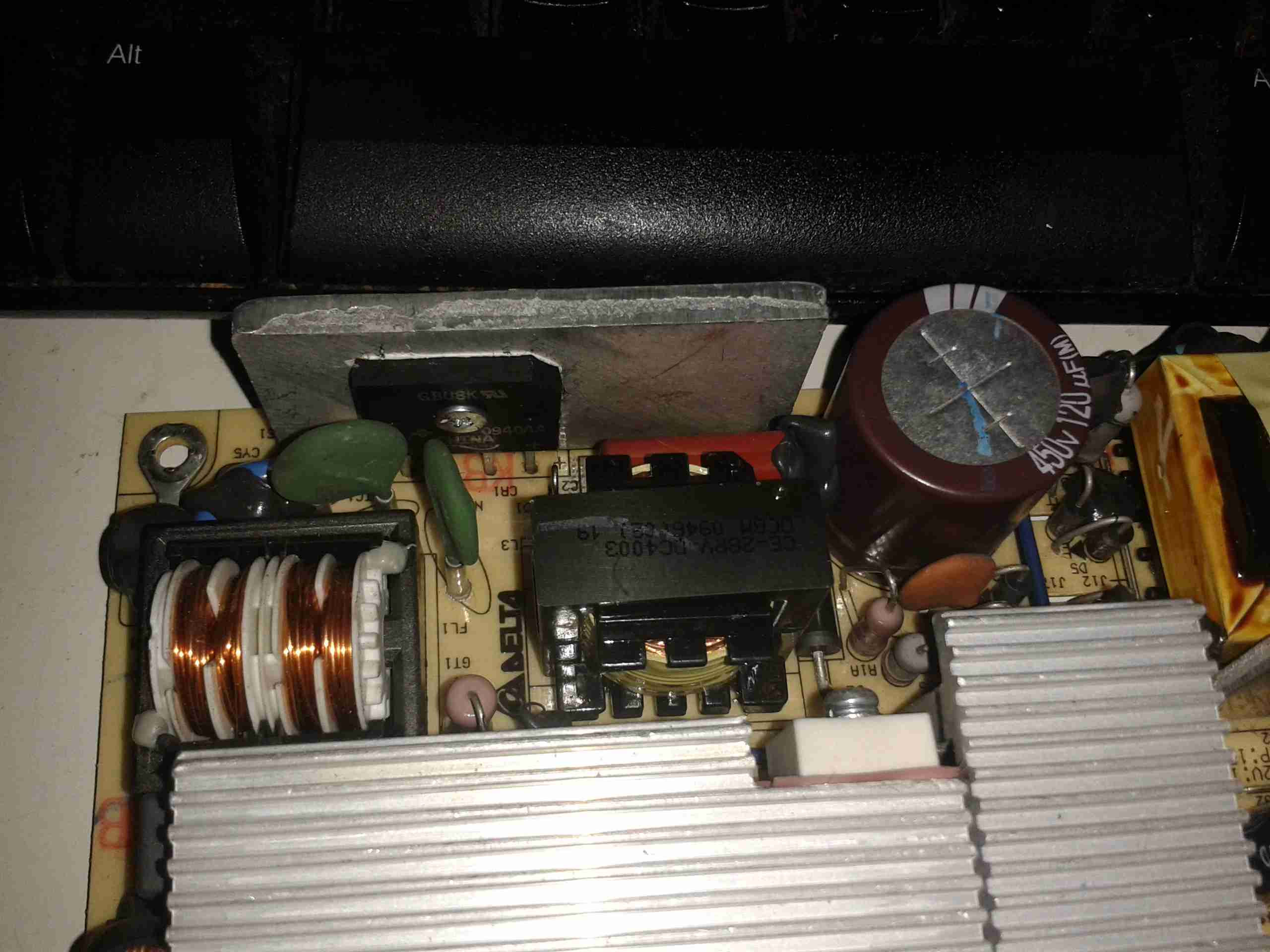
Mains Input
Above is the mains input section of the PSU, with a large common-mode choke on the left, bridge rectifier in the centre, and the large filter capacitor on the right. These can store a lot of energy when disconnected from the mains, and while they should have a discharge resistor fitted to safely drain the stored energy, they aren’t to be relied on for safety!
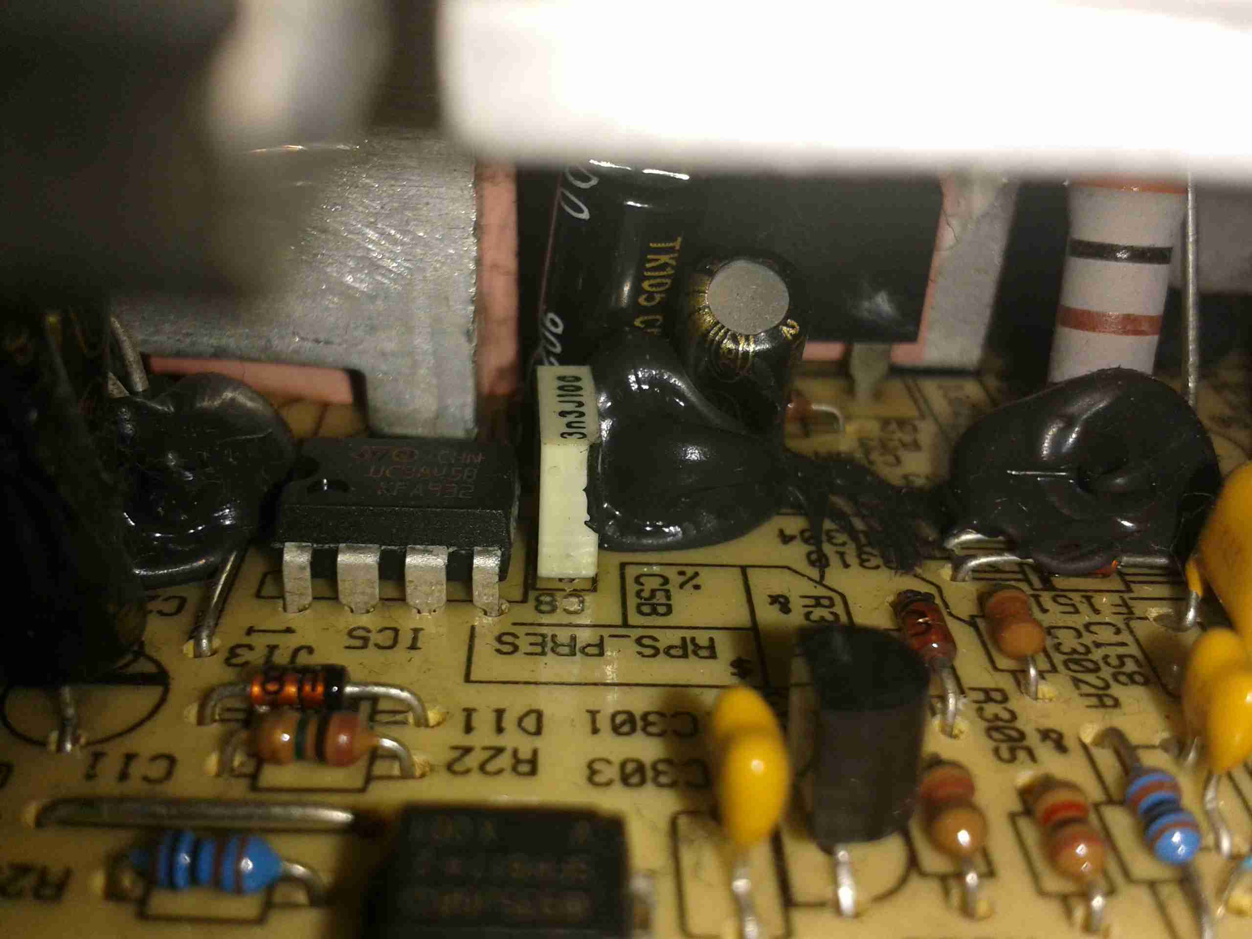
Once the supply has it’s main high voltage DC rail, this is switched into the main transformer by a pair of very large transistors – these are hidden from view on the large silver heatsinks at the bottom of the image. These transistors are themselves driven with a control IC, in the case of this supply, it’s a UC3844B. This IC is hidden under the large heatsink, but is just visible in the below photo. (IC5).
Control ICMain Switching Transformer
Here’s the main switching transformer, these can be much smaller than a conventional transformer due to the high frequencies used. This supply operates at 500kHz.
After the main transformer, the output is rectified by a pair of Schottky diodes, which are attached to the smaller heatsink visible below the transformer, before being fed through a large toroidal inductor & the output filter capacitors.
All this filtering on both the input & the output is required to stop these supplies from radiating their operating frequency as RF – a lot of cheap Chinese switching supplies forego this filtering & as a result are extremely noisy.
After all this filtering the DC appears at the output as usable power.
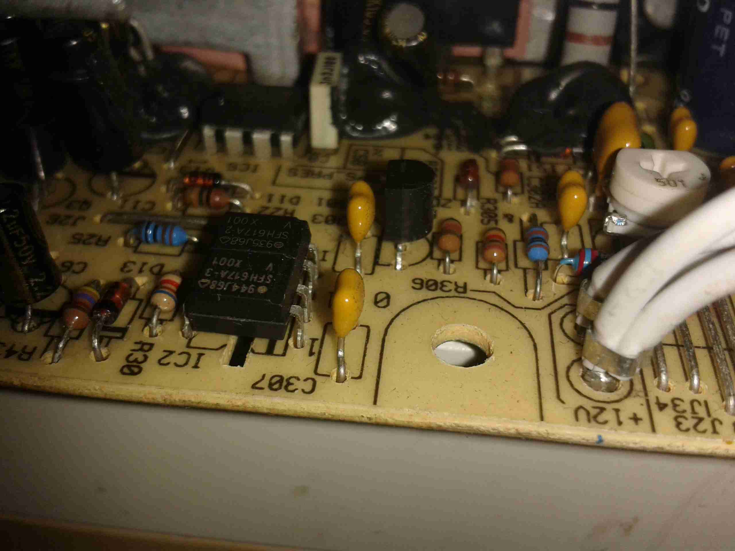
Getting back to regulation, these supplies read the voltage with a resistor divider & feed it back to the mains side control IC, through an opto-isolator. (Below).
Feedback Loop
The opto isolators are the black devices at the front with 4 pins.
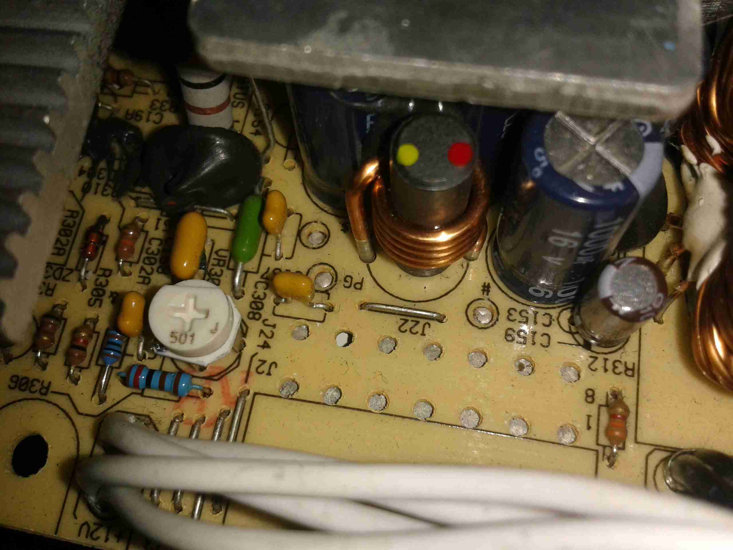
Regulator Adjustment
For a more in-depth look at the inner workings of SMPS units, there’s a good article over on Hardware Secrets.
My modification is simple. Replacing R306 (just below the white potentiometer in the photo), with a slightly smaller resistor value, of 2.2KΩ down from 2.37KΩ, allows the voltage to be pulled lower on the regulator. This fools the unit into applying more drive to the main transformer, and the output voltage rises.
It’s important to note that making too drastic a change to these supplies is likely to result in the output filter capacitors turning into grenades due to overvoltage. The very small change in value only allows the voltage to rise to 13.95v max on the adjuster. This is well within the rating of 16v on the output caps.
Now the voltage has been sucessfully modified, a new case is on the way to shield fingers from the mains. With the addition of a couple of panel meters & output terminals, these supplies will make great additions to my shack.
To provide more run time with the conversion to petrol & spark ignition, I have also upgraded the on-board electronics supply to compensate for the extra ~650mA draw of the ignition module.
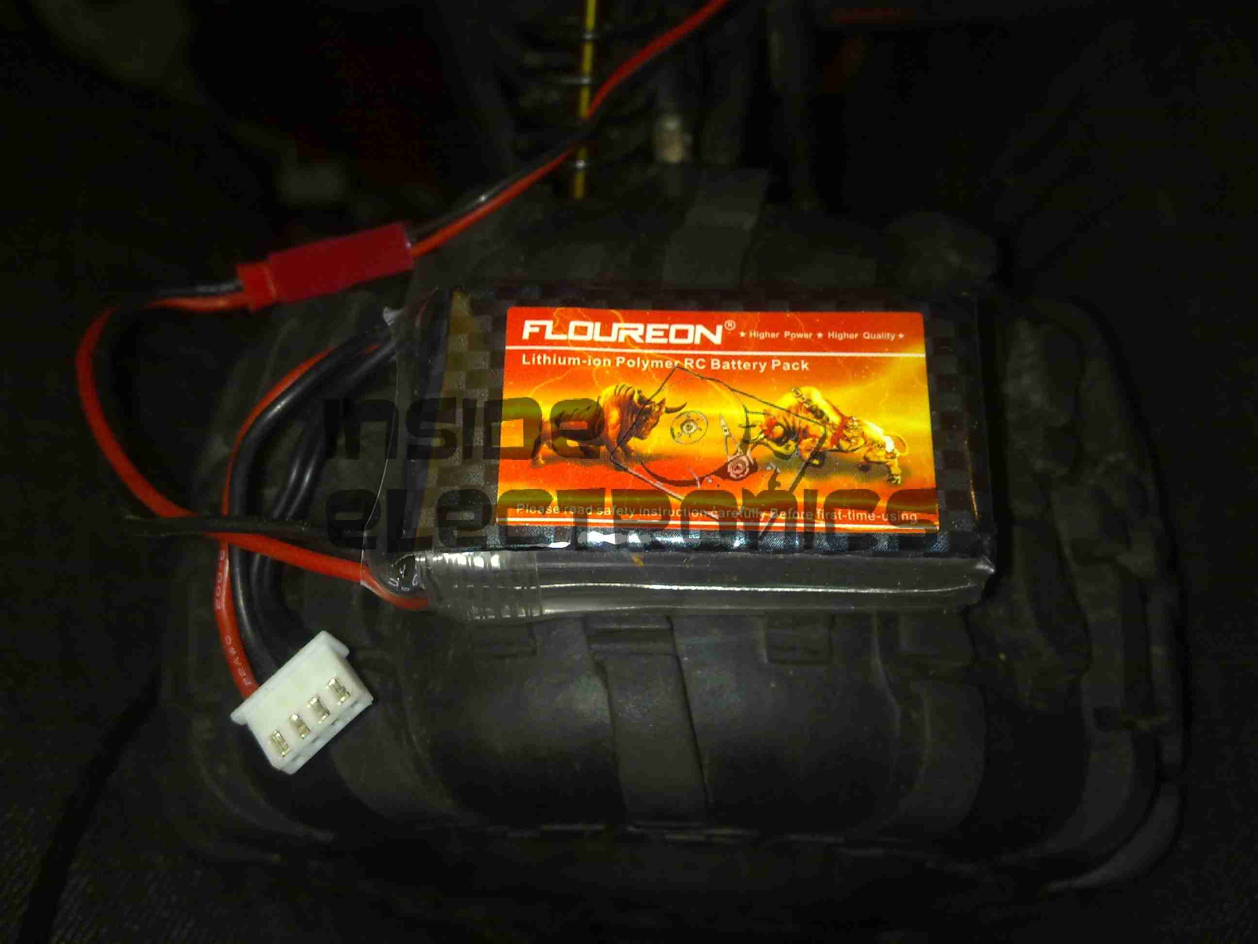
This modification is centred around a 3S Lithium-Polymer battery pack, providing a nominal 11.1v to a voltage regulator, which steps down this higher voltage to the ~6v required by the receiver & servo electronics.
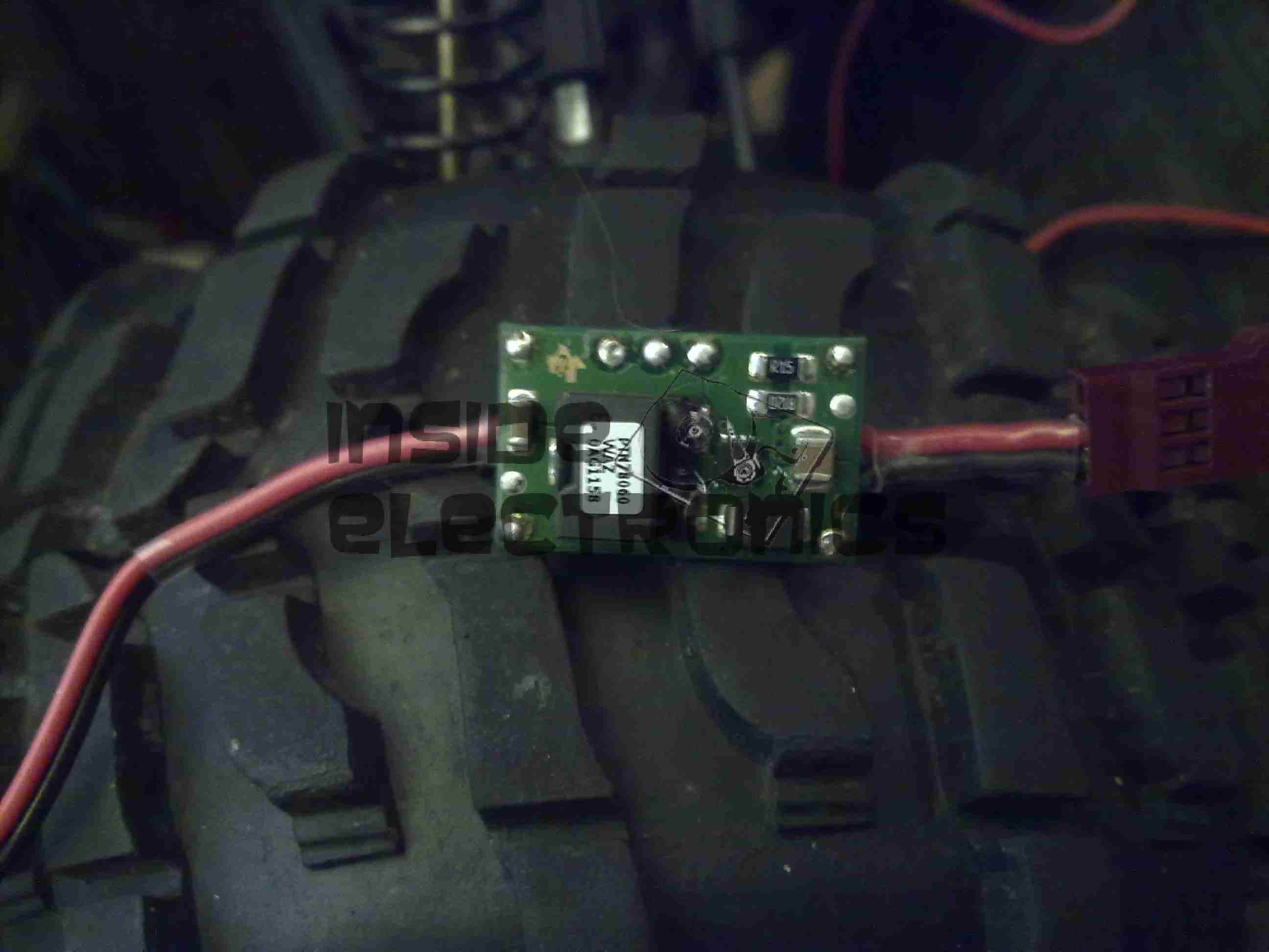
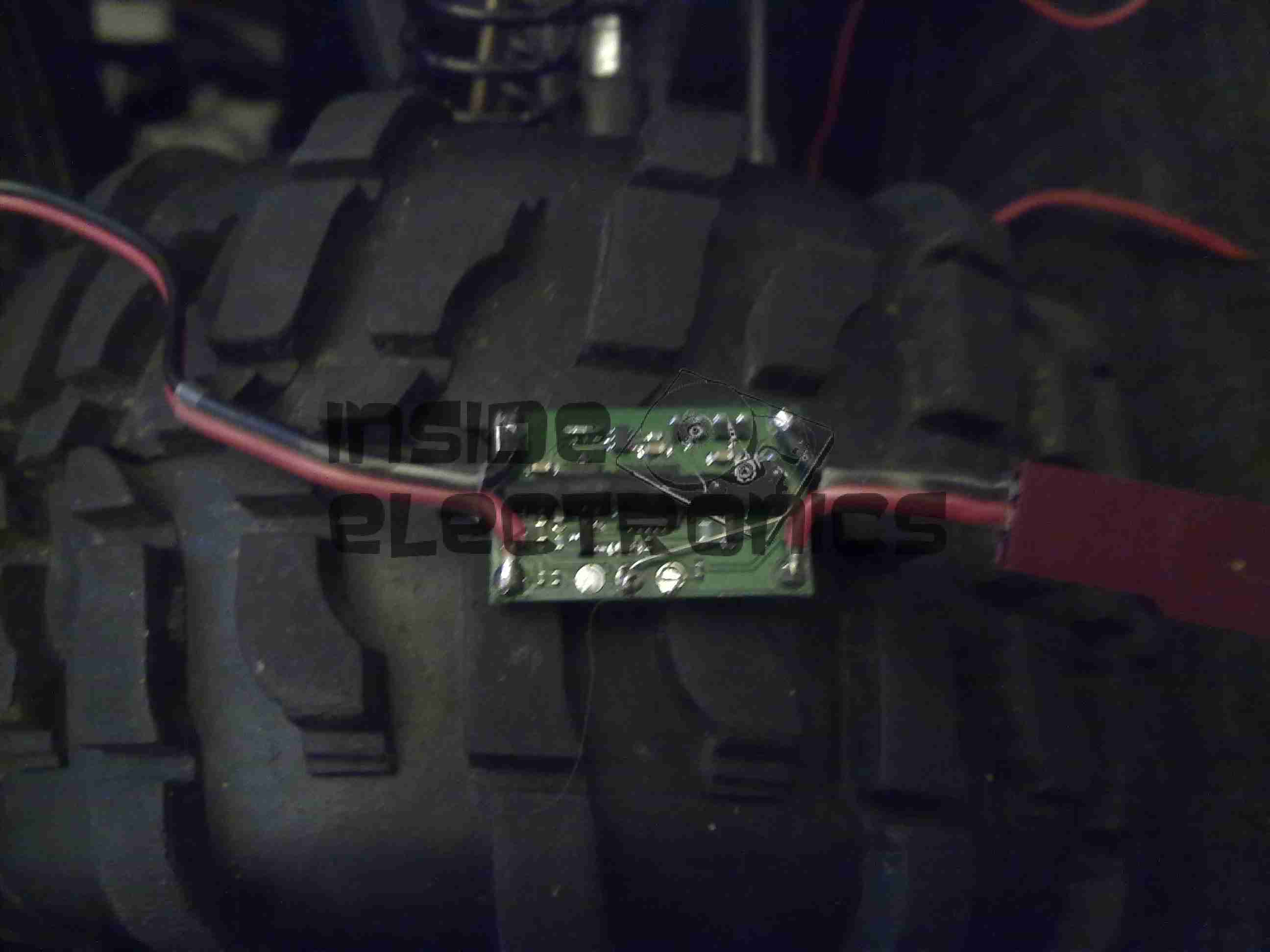
Power RegulatorPower Regulator
The regulator, shown above, is a Texas Instruments PTN78060WAZ wide-input voltage adjustable regulator. This module has an exceptionally high efficiency of ~96% at it’s full output current of 3A. The output voltage is set by a precision resistor, soldered to the back of the module, in this case 6.5v. Standard RC connectors are used on the regulator to allow connection between the power switch & the radio receiver.
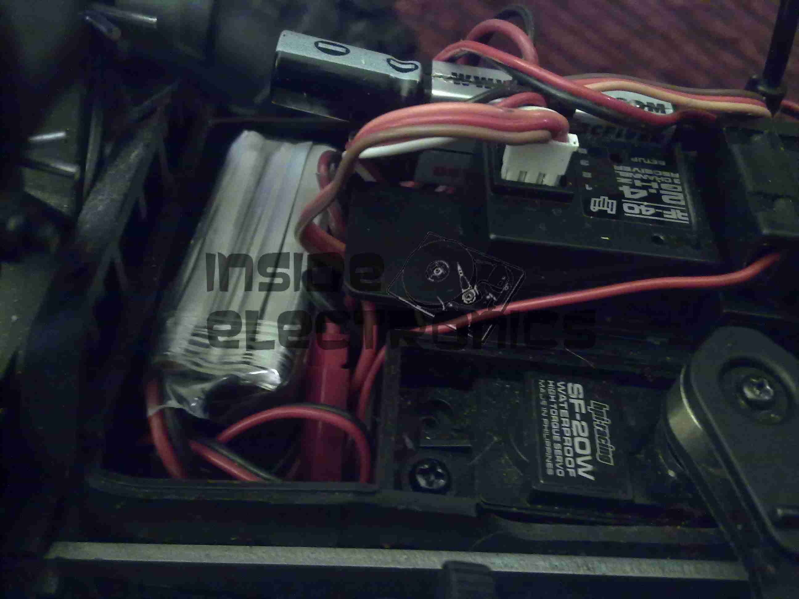
Receiver Box
Everything tucked away into place inside the receiver box. The 3S 1000mAh LiPo fits perfectly in the space where the original Ni-Mh hump pack was located.
The completely stable output voltage of the regulator over the discharge curve of the new battery gives a much more stable supply to the radio & ignition, so I should experience fewer dropouts. Plus the fact that the engine now relies on power from the receiver pack to run, it’s a built in fail safe – if the power dies to the receiver, the engine also cuts out.
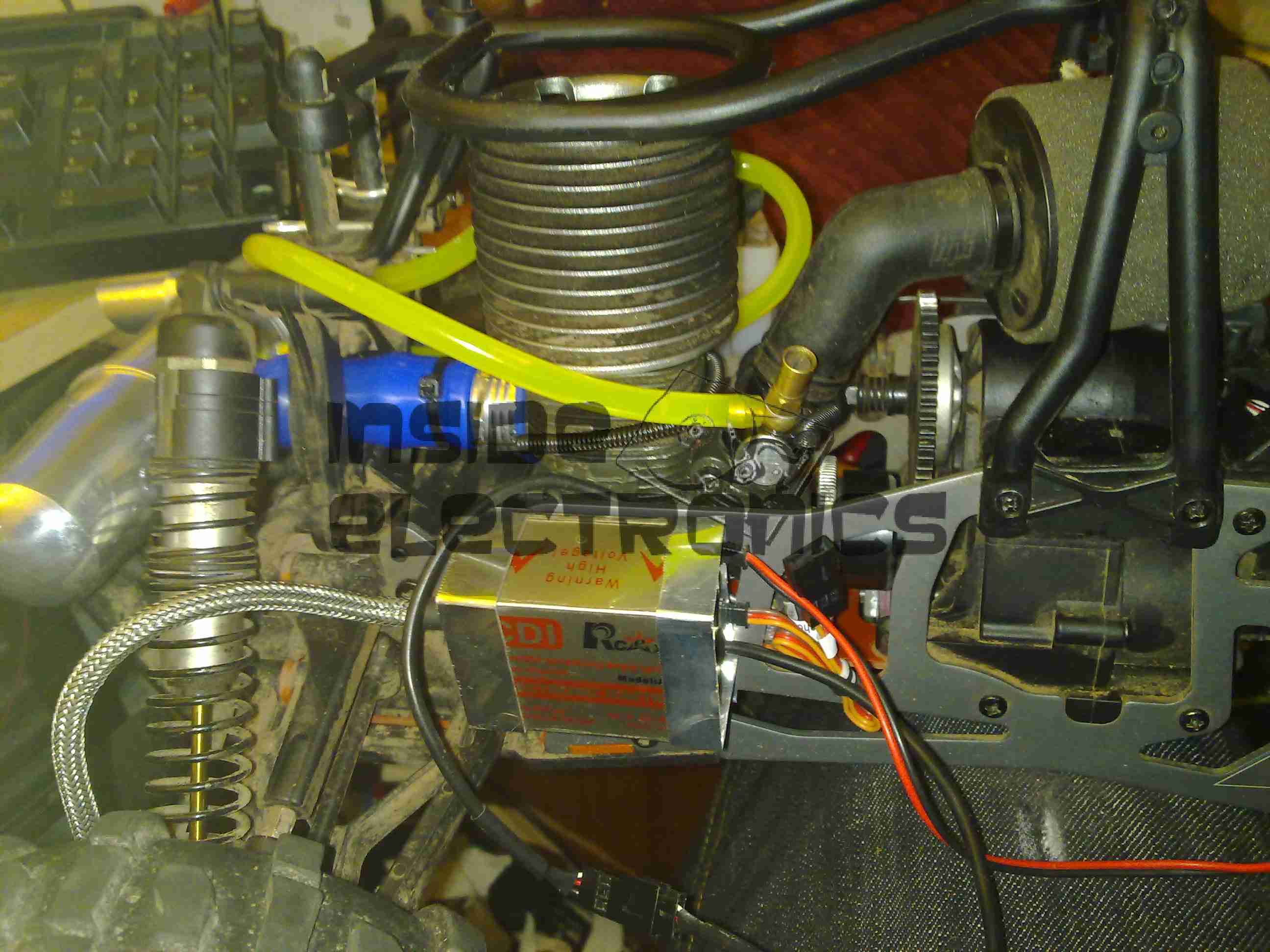
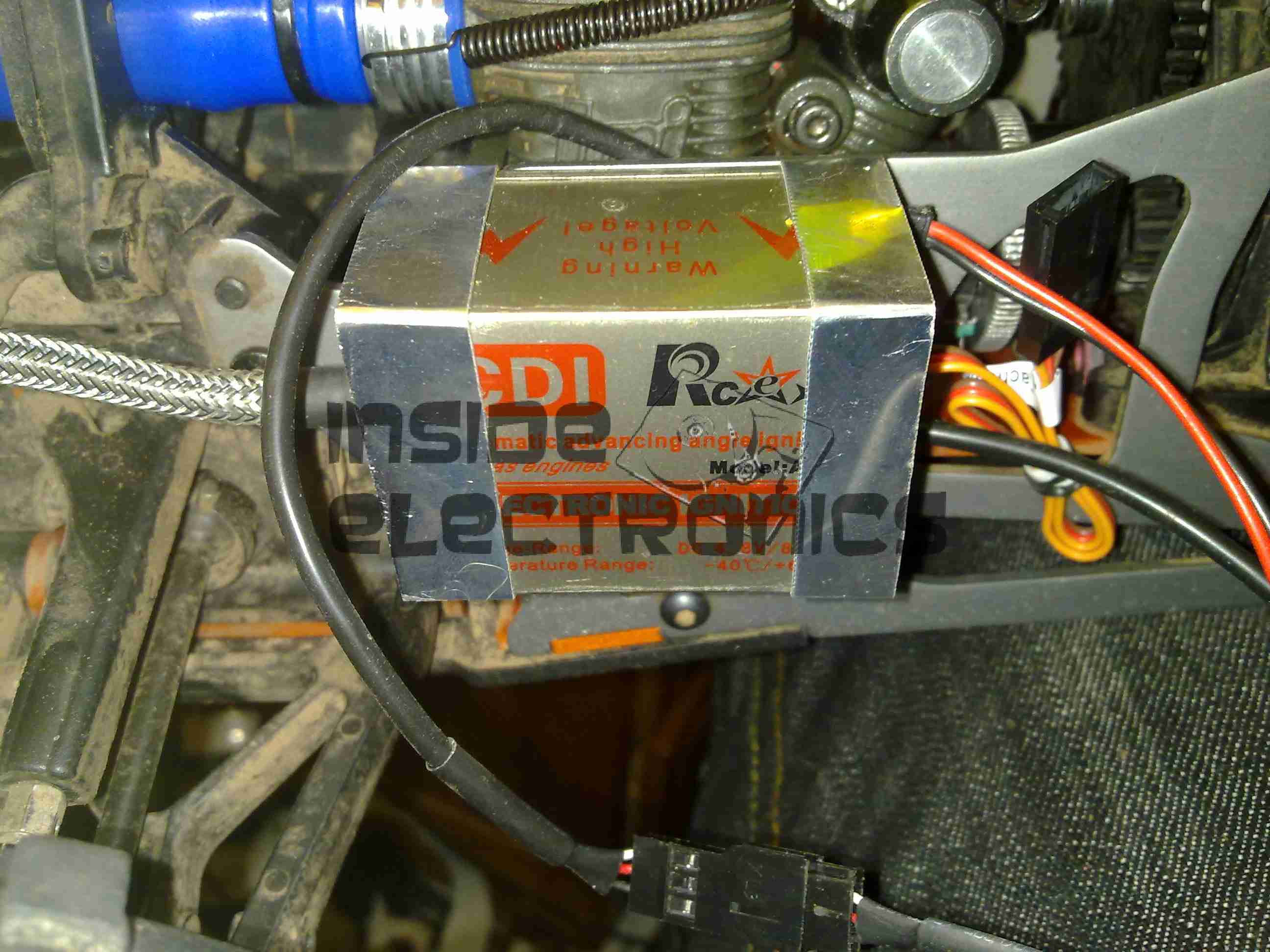
The engine now with it’s required ignition sensor, it is now mounted back on the chassis of the model. I have replaced the stock side exhaust with a rear silencer, so I could fit the ignition module in place next to the engine.
For the mounting, I fabricated a pair of brackets from 0.5mm aluminium, bent around the module & secured with the screws that attach the engine bed plate to the TVPs. The ignition HT lead can be routed up in front of the rear shock tower to clear all moving suspension parts, with the LT wiring tucked into the frame under the engine.
In this location the module is within the profile of the model chassis so it shouldn’t get hit by anything in service.
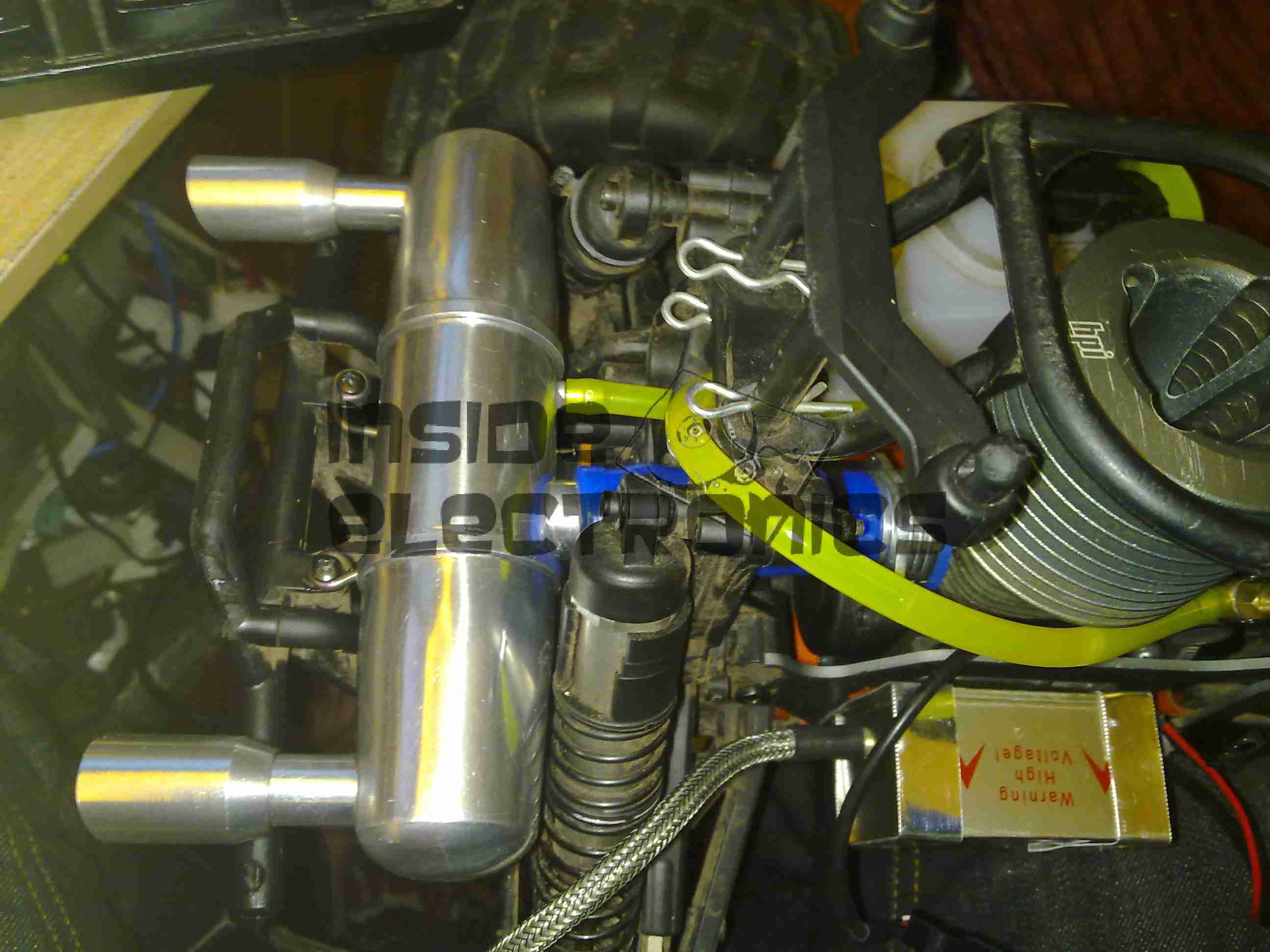
Rear Exhaust
New exhaust silencer fitted to the back of the model. This saves much space on the side of the model & allows the oily exhaust to be discharged away from the back wheel – no more mess to wipe up.
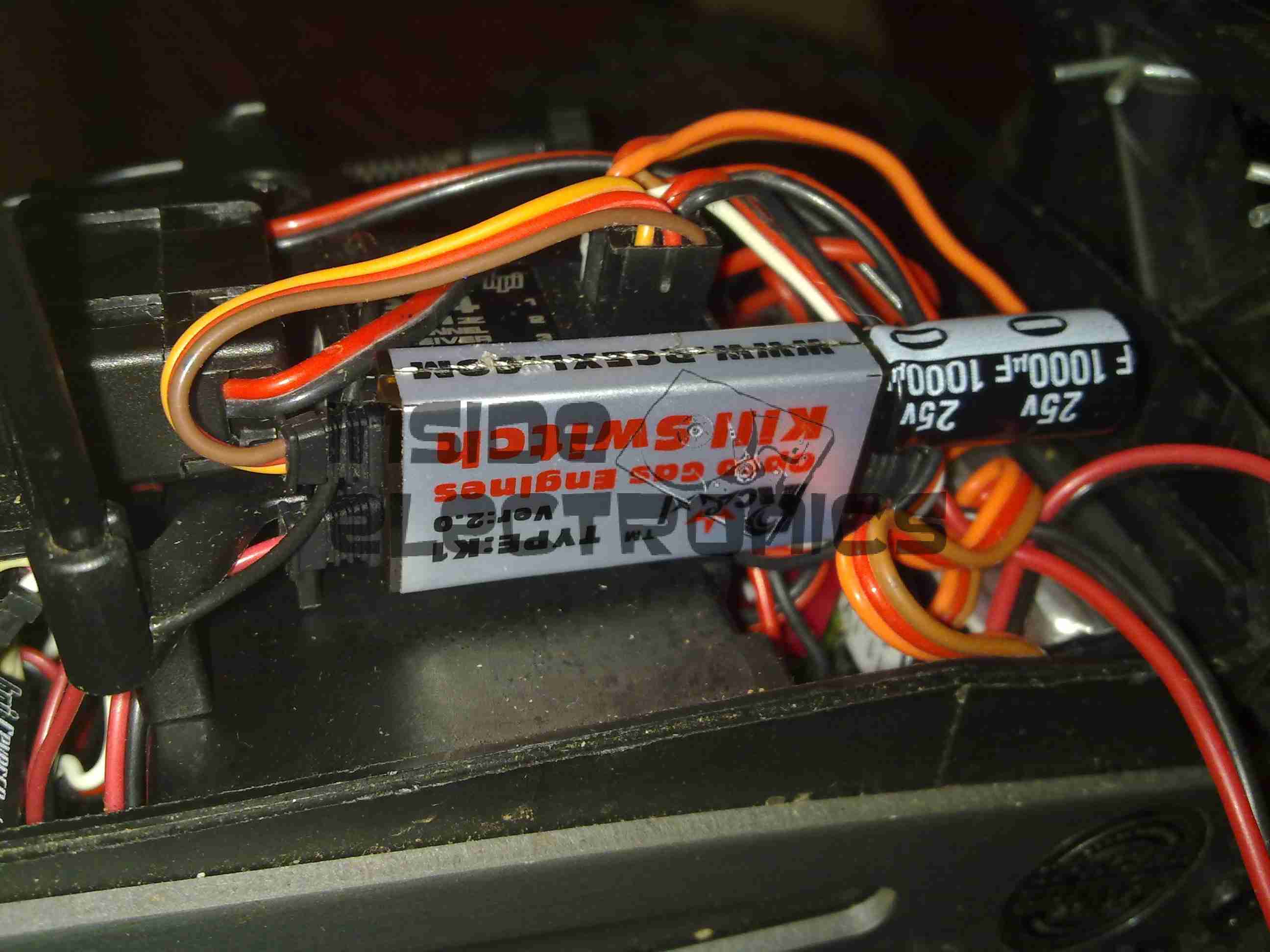
Kill Switch
The ignition switch fitted into the receiver box. This is wired into channel 3 of the TF-40 radio, allowing me to remotely kill the engine in case of emergency. I have fitted a 25v 1000µF capacitor to smooth out any power fluctuations from the ignition module.
The radio is running from a 11.1v 1Ah 3S LiPo pack connected to a voltage regulator to give a constant 6.5v for the electronics. I found this is much more reliable than the standard 5-cell Ni-MH hump packs.
Fuel Tank
The stock silicone fuel tubing has been replaced with Tygon tubing to withstand the conversion to petrol.
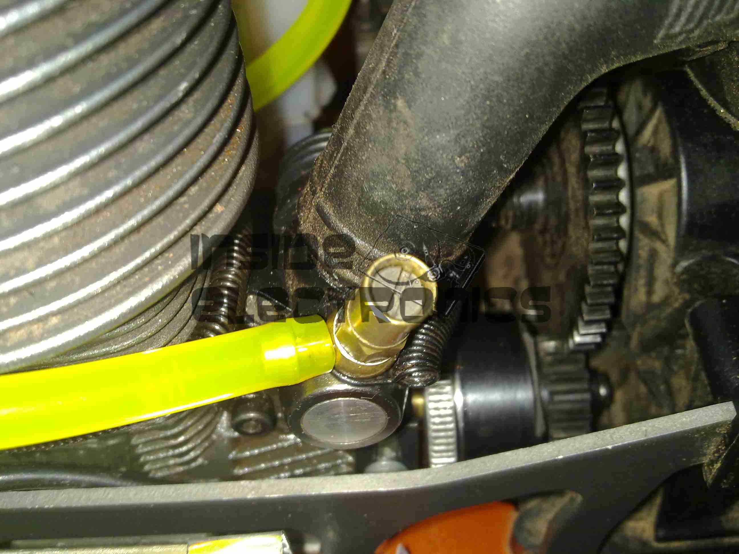
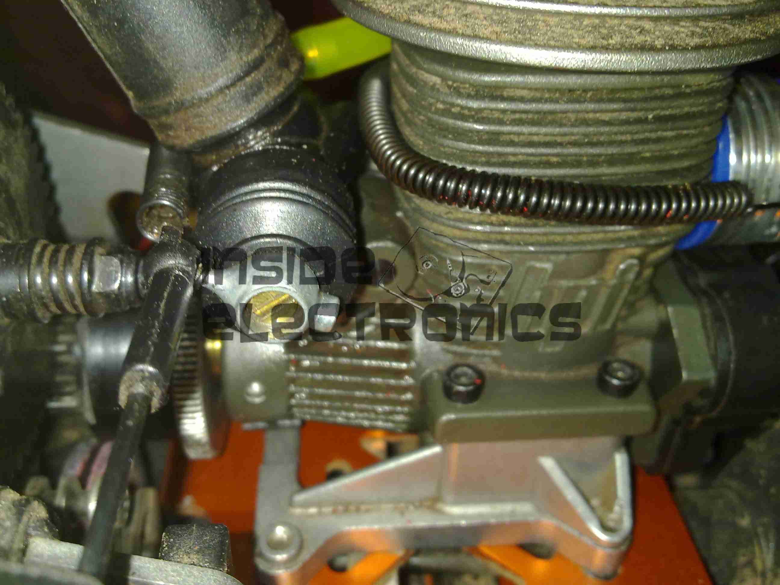
High Speed Needle
High speed needle tweaked to provide a basic running setting on petrol. This is set to ~1.5mm below flush with the needle housing.
Low Speed Needle
Low speed needle tweaked to provide a basic running setting on petrol. This is set to ~1.73mm from flush with the needle housing.
As petrol is a much higher energy density fuel, it requires much more air than the methanol glow fuel – ergo much leaner settings.
The settings listed should allow an engine to run – if nowhere near perfectly as they are still rather rich. It’s a good starting point for eventual tuning.
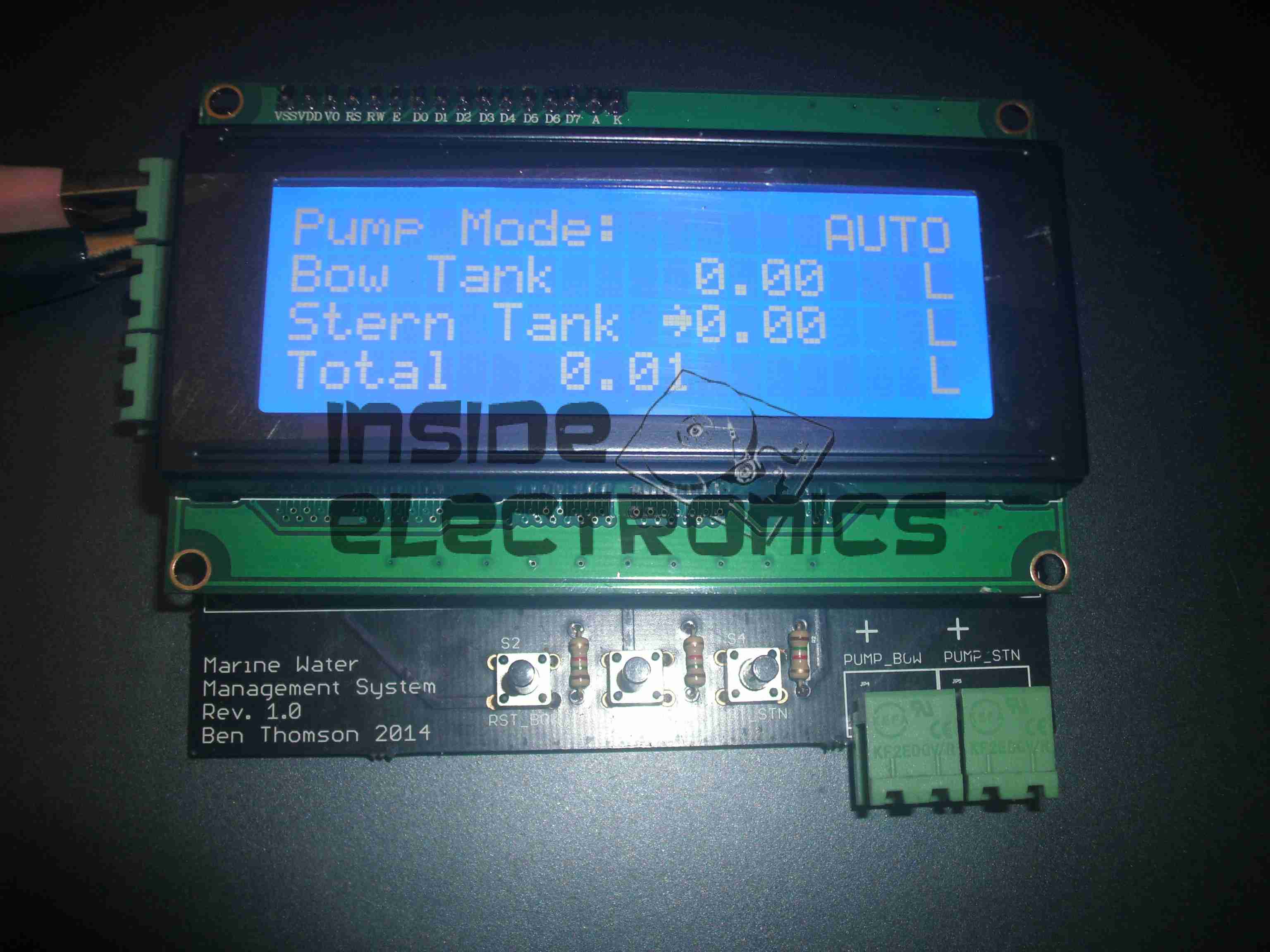
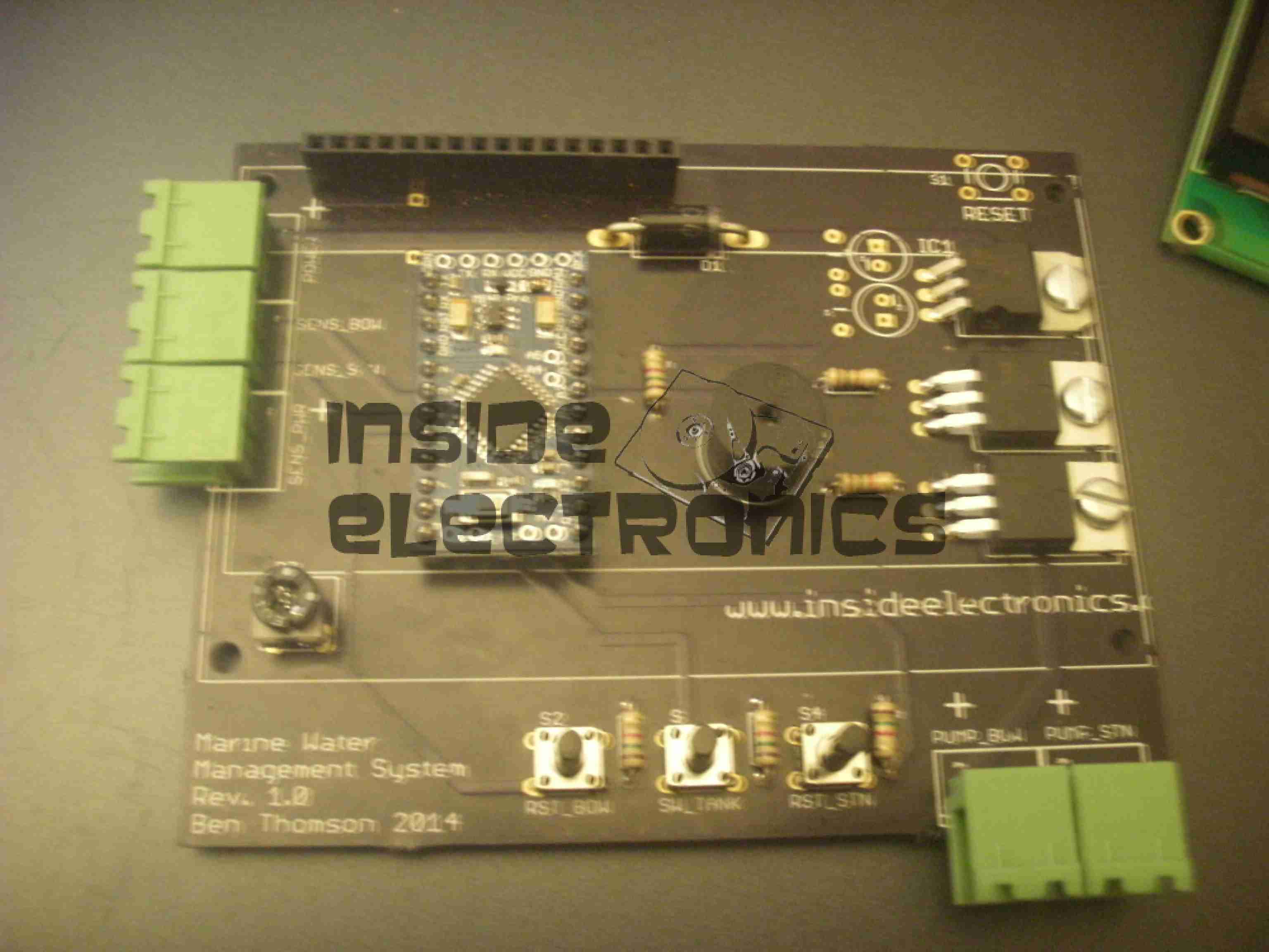
Having two separate water tanks on nb Tanya Louise, with individual pumps, meant that monitoring water levels in tanks & keeping them topped up without emptying & having to reprime pumps every time was a hassle.
To this end I have designed & built this device, to monitor water usage from the individual tanks & automatically switch over when the tank in use nears empty, alerting the user in the process so the empty tanks can be refilled.
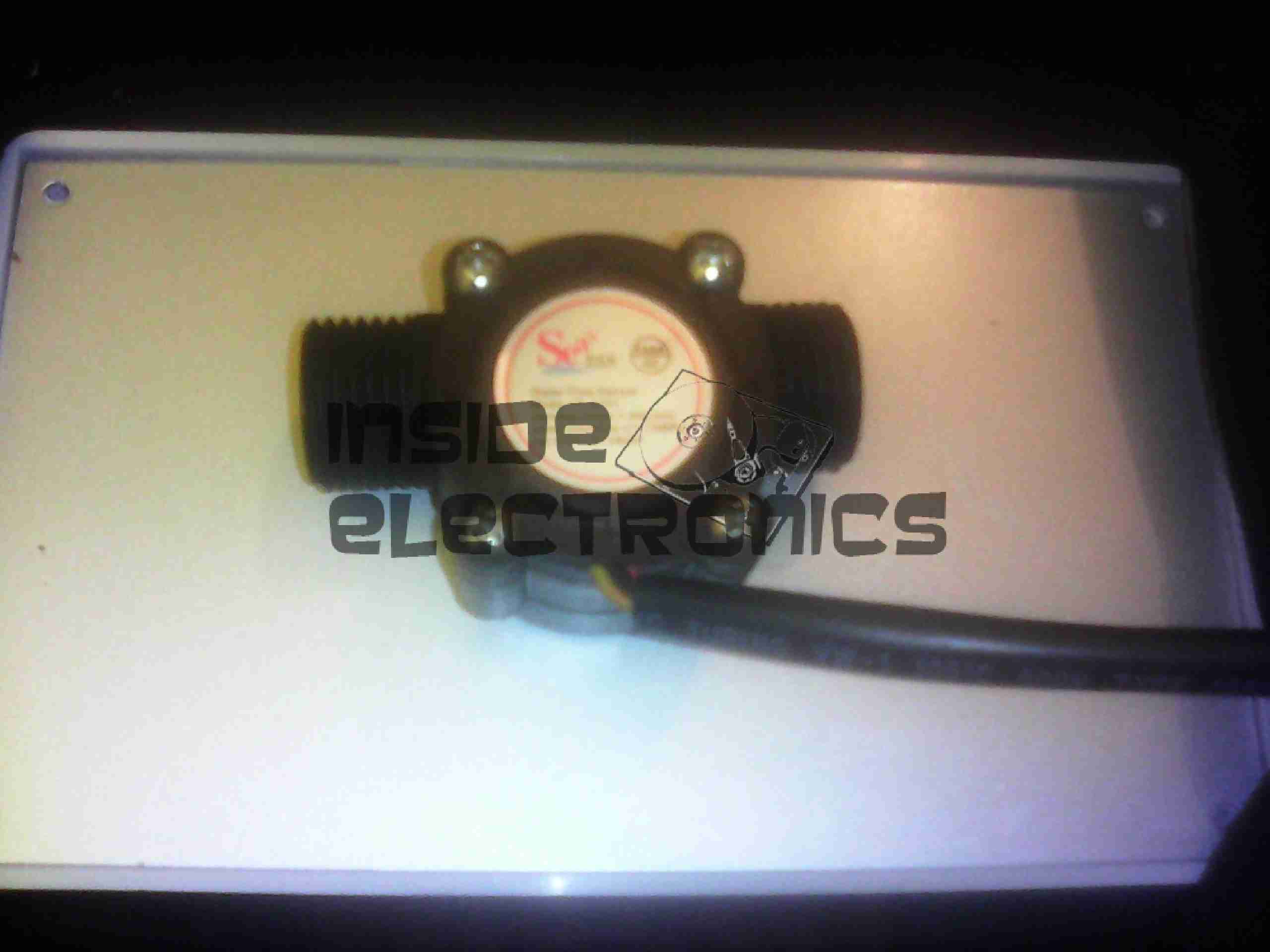
Based around an ATMega328, the unit reads a pair of sensors, fitted into the suction line of each pump from the tanks. The calculated flow is displayed on the 20×4 LCD, & logged to EEPROM, in case of power failure.
Water Flow Sensor
When the tank in use reaches a preset number of litres flowed, (currently hardcoded, but user input will be implemented soon), the pump is disabled & the other tank pump is enabled. This is also indicated on the display by the arrow to the left of the flow register. Tank switching is alerted by the built in beeper.
It is also possible to manually select a tank to use, & disable automatic operation.
Resetting the individual tank registers is done by a pair of pushbuttons, the total flow register is non-resettable, unless a hard reset is performed to clear the onboard EEPROM.
Main PCB
View of the main PCB is above, with the central Arduino Pro Mini module hosting the backend code. 12-24v power input, sensor input & 5v sensor power output is on the connectors on the left, while the pair of pump outputs is on the bottom right, switched by a pair of IRFZ44N logic-level MOSFETS. Onboard 5v power for the logic is provided by the LM7805 top right.
Code & PCB design is still under development, but I will most likely post the design files & Arduino sketch once some more polishing has been done.
This unit was bought from eBay to experiment with Magnetic Stripe cards, for little money. This unit is capable of reading & writing all 3 tracks, & both Hi-Co & Lo-Co card types.
Interfaced to a PC through USB, this has a built in PL2303 USB-Serial IC & requires 3A at 9v DC to operate.
The 3 Indicator LEDs on the top of the unit can be toggled by the included software for Power/OK/Fault condition signalling.
Unit Bottom
Bottom of the unit with the model labels.
Model Label
Closeup of the model label & serial number.
PCB Bottom
Here the bottom cover has been removed, showing the main PCB. The pair of large ICs bottom center interface with the magnetic heads. The IC above them has had the markings sanded off.
USB-Serial Interface
Closeup of the Prolific PL-2303 USB-Serial converter IC.
PCB Top
Here the connections to the R/W heads are visible, current limiting resistors at the left for the write head, a pair of signal relays, a pair of optoisolators & a LM7805 linear voltage regulator.
LEDs
Here is the trio of indicator LEDs on a small sub-board.
Frame Bottom
The PCB has been removed from the main frame here, the only component visible is the rotary encoder.
Rotary Encoder
The rotary encoder has a rubber wheel fitted, which reads the speed of the card as it is being swiped for writing. This allows the control logic to write the data to the stripe at the correct rate for the speed of the card. This allows the unit to write cards from 5-50 inches per second speed.
The Write head is directly behind the rubber pressure roller.
Read/Write Heads
Here you can see the R/W head assembly. The write head is on the right, read on the left. When a card is written to, it immediately gets read by the second head for verification.
This is a device designed to reset Epson brand ink cartridges that are reportedly out of ink, so they again report full to the printer Here is the front of the unit, with the guide for attaching to a cartridge.
PCB Back
Back of the device removed. 3 button cells provide power to the PCB. Indicator LED sticks out of the top of the device for reset confirmation.
Row of pads on far left edge of the PCB are presumably a programming header for the uC on the other side of the board.
PCB Front
Here is the front of the PCB, main feature being the grid of pogo pins to connect to the cartridge chip. IC on lower right of that is a MSP430F2131 uController, a Texas Instruments part.
The IC directly to the left of the pogo pin bed is a voltage regulator, to step down the ~4.5v of the batteries down to the ~3.3v that the uC requires.
Tip Jar
If you’ve found my content useful, please consider leaving a donation by clicking the Tip Jar below!
All collected funds go towards new content & the costs of keeping the server online.