Posted on Leave a comment

Stripboard Magic – A Call For Information

Some time ago I posted about an ancient piece of EDA software called Stripboard Magic, which was made by a small British company by the name of Ambyr. I have been hosting copies of this now long-dead software for some time, as it still seems to be in popular demand long after being abandoned by it’s creators. I have been contacted by a reader about the existence of Service Packs for this application, which neither of us have been able to locate.

From what I have been able to gather, Ambyr ceased trading around 1999-2000, after having sold the rights to distribute Stripboard Magic to Maplin Electronics. What I’m not certain of is the timeframe of these service packs appearing, or where they could originally be found, the Ambyr website apparently vanished about 6 months after Stripboard Magic was originally released, but they were presumably intended to make the application easier to use & less buggy.
Unfortunately the timeframe for the company’s existence was before the Wayback Machine started archiving the internet, and the only record they have of Ambyr is a domain holding page dating back to 2000.

If there are any readers who have copies of these service packs, or some information on where they can be found, or indeed any more information in general about this seemingly short-lived company, please drop a comment or E-Mail me directly through the Contact Page. Inquiring minds need to know 😉

73s, de 2E0GXE

Posted on 1 Comment

Velleman MK179

Completed Kit
Completed Kit

This is the Velleman MK179 Proximity Card Reader, which is supplied in kit form. In the image above you can see the completed kit, the read coil is etched onto the black PCB on the left. Bringing a recognised card close to the coil operates the relay on the main PCB for a programmable amount of time.

Main PCB
Main PCB

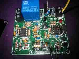
Closeup of the main PCB, 12v DC input at top right. Left IC is an LM358 dual Op-Amp, the IC on the right is a PIC12F629 with Velleman’s custom firmware.
Logic power is supplied to the ICs & the oscillator from the LM7805 regulator at the top of the PCB. The relay is a standard 15A SPDT 12v coil relay, with the switch contacts broken out onto the screw terminals on the left.

Schematic Diagram
Schematic Diagram

As it is not provided with the kit, unlike other Velleman kits, here is the schematic for this.


Posted on 1 Comment

MSR605 3-Track Magnetic Stripe Writer

MSR605
MSR605

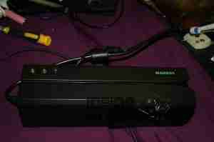
This unit was bought from eBay to experiment with Magnetic Stripe cards, for little money. This unit is capable of reading & writing all 3 tracks, & both Hi-Co & Lo-Co card types.
Interfaced to a PC through USB, this has a built in PL2303 USB-Serial IC & requires 3A at 9v DC to operate.
The 3 Indicator LEDs on the top of the unit can be toggled by the included software for Power/OK/Fault condition signalling.

Unit Bottom
Unit Bottom

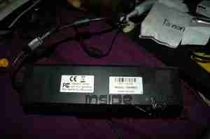
Bottom of the unit with the model labels.

Model Label
Model Label

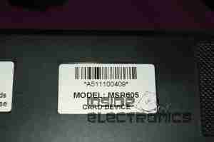
Closeup of the model label & serial number.

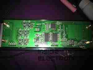
PCB Bottom
PCB Bottom

Here the bottom cover has been removed, showing the main PCB. The pair of large ICs bottom center interface with the magnetic heads. The IC above them has had the markings sanded off.

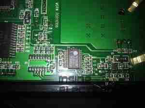
USB-Serial Interface

Closeup of the Prolific PL-2303 USB-Serial converter IC.

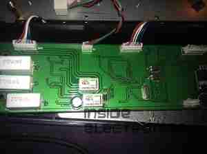
PCB Top
PCB Top

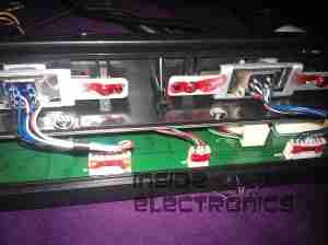
Here the connections to the R/W heads are visible, current limiting resistors at the left for the write head, a pair of signal relays, a pair of optoisolators & a LM7805 linear voltage regulator.

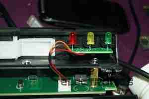
LEDs
LEDs

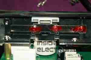
Here is the trio of indicator LEDs on a small sub-board.

Frame Bottom
Frame Bottom

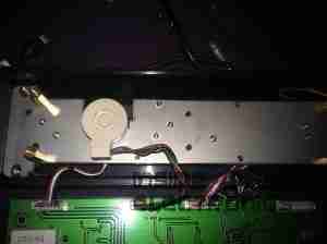
The PCB has been removed from the main frame here, the only component visible is the rotary encoder.

Rotary Encoder
Rotary Encoder

The rotary encoder has a rubber wheel fitted, which reads the speed of the card as it is being swiped for writing. This allows the control logic to write the data to the stripe at the correct rate for the speed of the card. This allows the unit to write cards from 5-50 inches per second speed.
The Write head is directly behind the rubber pressure roller.

Read/Write Heads
Read/Write Heads

Here you can see the R/W head assembly. The write head is on the right, read on the left. When a card is written to, it immediately gets read by the second head for verification.

The drivers for this unit are also available here: Magcard Writer Drivers

Posted on Leave a comment

USB Multi Card Reader

Card Reader
Card Reader

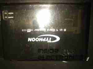
Here is a cheap USB 8-in-1 card reader. Power & Access LEDs are on top left.

PCB Top
PCB Top

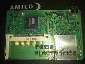
Top of the PCB. The OTi IC is the interface IC to the USB port, part number is OTI002126. Card sockets on the top here are CF/Microdrive & Memory Stick.

PCB Bottom
PCB Bottom

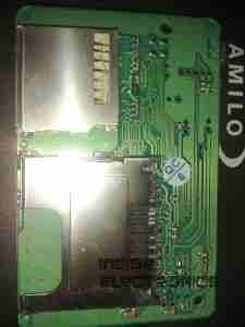
Bottom of the PCB with the SD/MMC, Smart Media

Posted on Leave a comment

HP Photosmart 375

Top
Top

This is a HP PhotoSmart 375 portable photo printer. With built in card reader, screen & PictBridge.
Top of the printer showing the UI Buttons & Screen.

Front
Front

Front of the unit, card reader slots at the top, Pictbridge USB connector at top left. Paper out slot at bottom. Cartridge door is on the right.

Cartridge Door
Cartridge Door

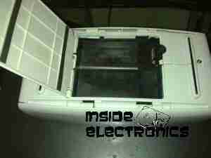
Here the cartridge door is open. Takes HP 95 Tri-Colour Inkjet Cartridge.

Battery Compartment
Battery Compartment

Battery compartment on the bottom of the unit. A Li-Ion battery pack can be installed here for mobile photo printing.

Bottom Label
Bottom Label

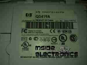
Specifications label.

USB + Power
USB + Power

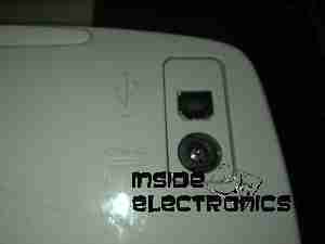
Power adaptor & USB connection for PC use.

Paper Tray
Paper Tray

Rear door opened. Showing the paper feed tray.

Paper Feeder
Paper Feeder

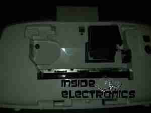
Rear door has been removed in this shot. Paper feed roller & platen roller can be seen here.

Rear Cover Paper Feeder

Paper holder attached to rear door.

Top Cover
Top Cover

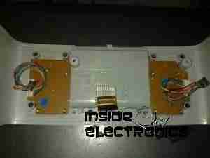
Bottom of the top cover, with connections for the buttons & LCD panel.

Main PCB
Main PCB

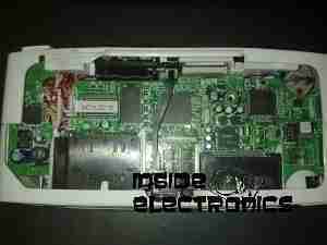
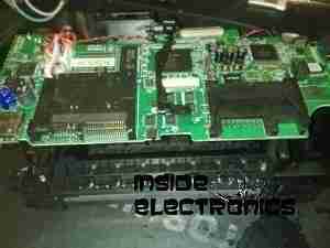
This is the main PCB of the unit. Controls all aspects of the printer. CPU in center, card reader sockets are along bottom edge. various support circuitry surrounds the CPU.

Rear
Rear

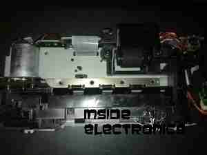
Rear shell has been removed here. Showing the main frame & the carriage drive motor on the left.

Carriage Drive
Carriage Drive

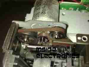
Closeup of the carriage drive motor & timing belt system. All the motors in this printer are DC servo motors, not steppers.

Main Drive Motor
Main Drive Motor

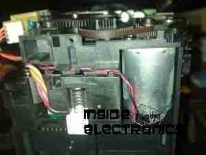
Main drive motor, feeds paper, drives rollers, operates cleaning mechanism for the inkjets.

Shaft Encoder
Shaft Encoder

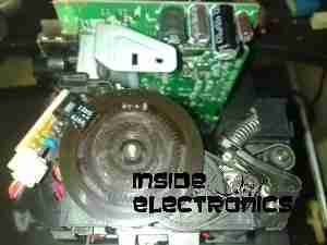
Mainshaft encoder. Main drive motor is bottom right hand side with timing belt drive.

CPU
CPU

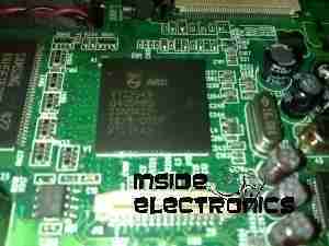
Closeup of the CPU. This is a Phillips ARM chip, unknown spec.

Card Reader Sockets
Card Reader Sockets

Detail of the card reader sockets, this unit takes all current types of Flash memory card.

HP 95 Tri-color Inkjet Print Cartridge