Posted on 2 Comments

PiHole Status Display – Official Raspberry Pi LCD

PiHole Status Display

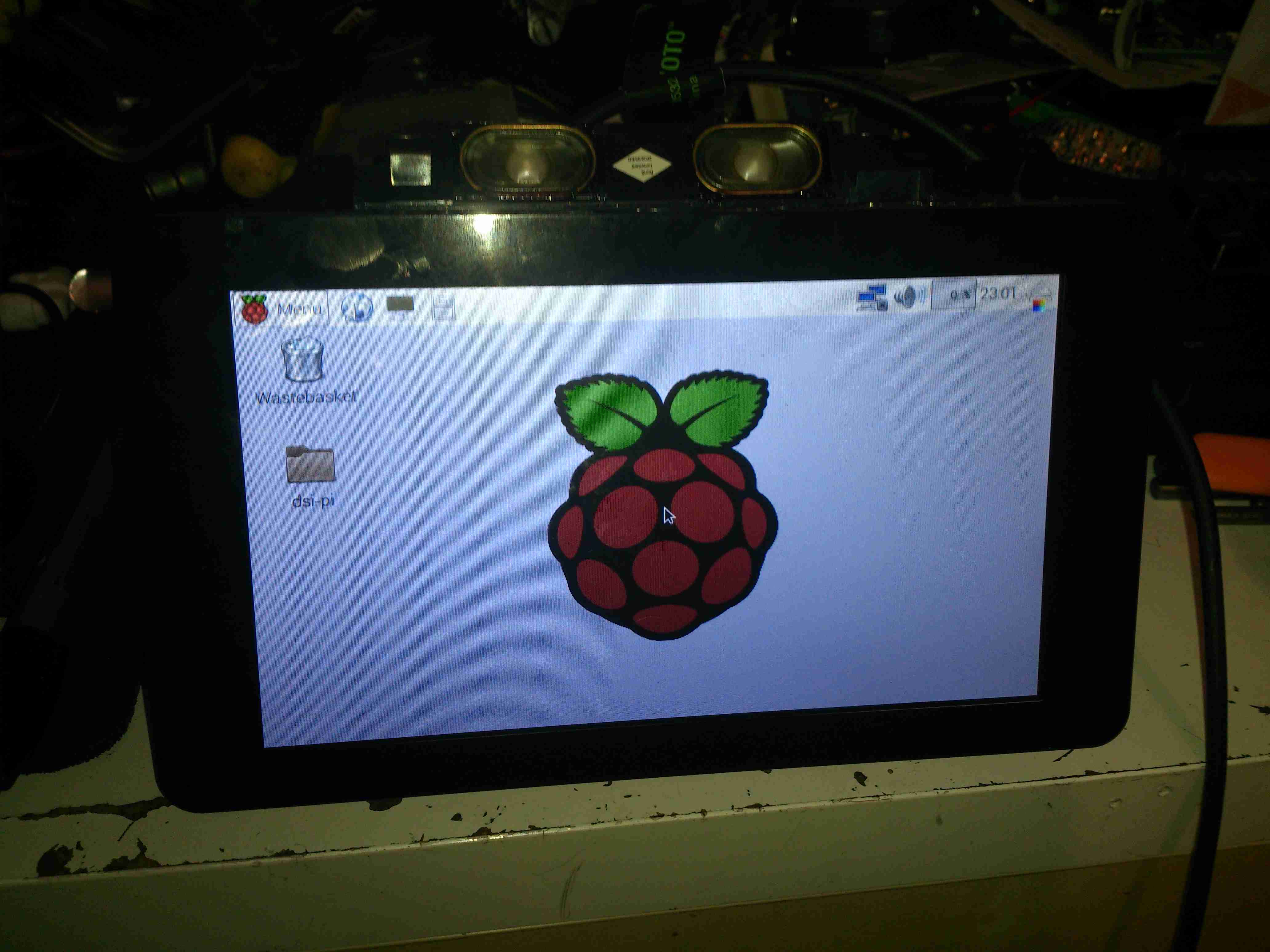
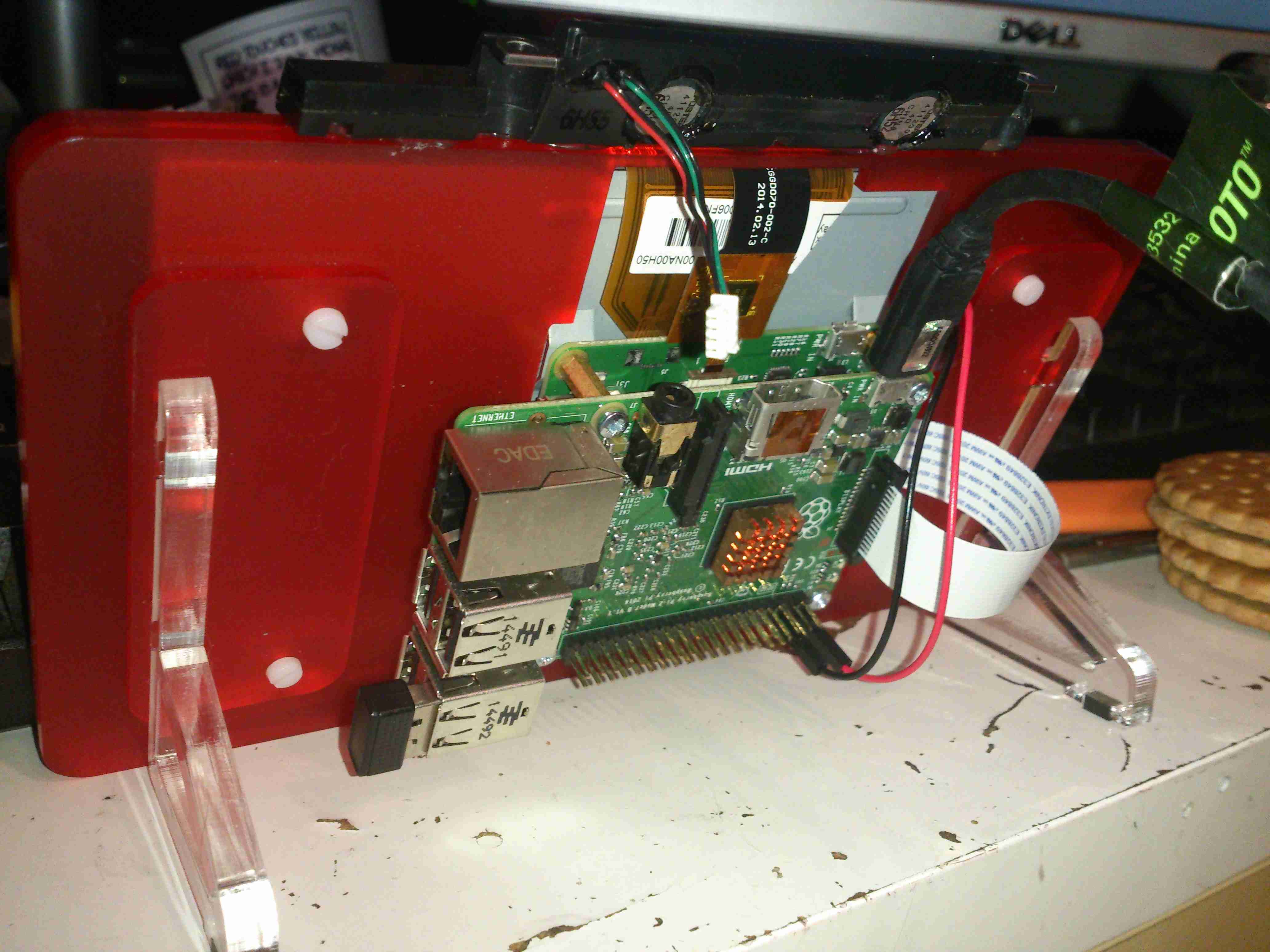
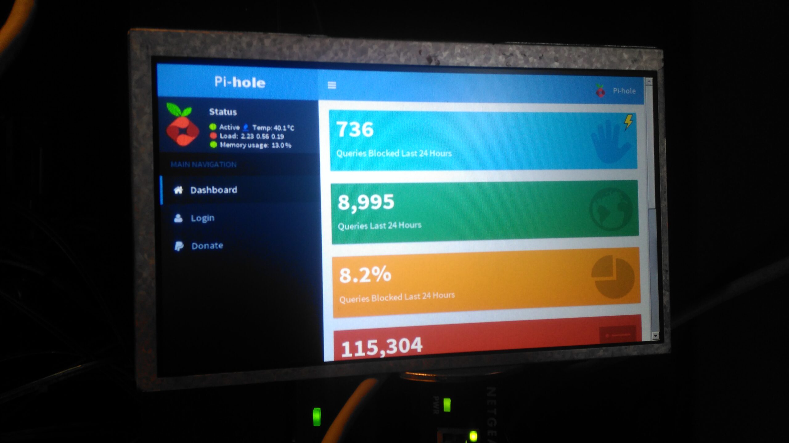
On my home network I have a system running PiHole – a DNS server that blocks all unwanted traffic, such as ads. Since I have an official Pi LCD with a broken touch panel, I decided to use the bare LCD as a status display for PiHole.

This requires some extra packages installing onto the base system after PiHole is installed & configured, and the interface automatically starts on bootup. I used the latest Raspbian Jessie Minimal image for this system, and ran everything over a SSH connection.

First thing, get the required packages installed onto the Pi:

Once these are installed, it’s time to configure the startup script for Midori to display the status page. Create StartMidori.sh in /home/pi and fill with the following:

This script disables all power management on the system to keep the LCD on, starts unclutter to hide the mouse pointer and finally starts the Matchbox Window Manager to run Midori, which itself is set to fullscreen mode, and the URL of the admin panel is provided.
The next step is to test, give the script executable permissions, and run the script:

Once this is run, the LCD should come to life after a short delay with the PiHole stats screen. Close the test & return to the terminal by hitting CTRL+C.

Now the Pi can be configured to autorun this script on boot, the first thing to do here is to enable autologin on the console. This can be done with raspi-config, select Option 3 (Boot Options), then Option B1 (Desktop/CLI), then Option B2 (Console Autologin). When prompted to reboot, select No, as we’ll be finishing off the config before we reboot the system.

The next file to edit is /etc/rc.local, add the command to start the status browser up:

Here I’ve added in the command just above “exit 0”. This will start the browser as the last thing on bootup. The Pi can now be rebooted, and the status display should start on boot!

PiHole Status Display
Posted on 2 Comments

STVG-502 Karaoke Machine CRT

Image Display

Here’s the CRT circuitry from a tossed STVG-502 Karaoke Machine, which got a good soaking in Manchester’s brilliantly wet weather before I managed to get hold of it:

Main PCB
Main PCB

I didn’t do a full teardown of this unit, since it was soaking wet & smelled rather badly of sour milk, so instead I quickly gutted it for the useful parts. These machines are a combination of a CD+G player, CRT composite monitor for displaying the CD+G lyrics & a small audio amplifier & 3W speaker. Power is provided from the mains via a transformer, with both 12 & 24v windings. One half of the board has the audio amplifier sections, the other the CRT drive, running from the 12v & 24v supplies respectively. I chopped off the audio section, as that wasn’t needed.

Linear Regulator
Linear Regulator

On this huge heatsink is what I originally thought was the horizontal drive transistor is actually a 12v linear regulator – the board gets fed 16v AC. This is then run through a rectifier which will produce an approx 22v rail, and after the smaller transistor on the left used for power switching. The 22v then gets dropped through a 1/2W 1Ω resistor, then the linear regulator drops it down to 12v for the rest of the circuit – dissipating a goodly amount of power in the process.

Horizontal Output Transistor

This is in fact the horizontal drive transistor, a 2SD613, which according to the datasheet, is intended for audio amplifier output stage applications, not CRT drive. Regardless, it’s an 85v 6A NPN transistor, and does get a bit on the warm side, but was never given a heatsink from the factory.

CRT Drive IC
CRT Drive IC

All the drive signals for the CRT are taken care of by this single DIP IC – a CD1379CP from Silicore. Considering the older CRT-based devices I have, with entire boards twice the size of this one dedicated to discrete components required to drive a CRT, this is definitely an advance in technology. Very few external components are being used, and no custom magnetics.

Video Input
Video Input

The video signal comes in from the CD+G player module on this connector, it’s a standard composite input. The composite video is fed into an amplifier after the controller IC. This video amp is powered from a 140v rail from the flyback transformer, to give enough signal to drive the CRT cathode.

LOPT
LOPT

The high voltage transformer is a BSH8-N5513L, I’ve not been able to find any data on this, but it looks like a standard off the shelf transformer from the listings on the Chinese supplier sites. There are very few support components around here, just a couple of diodes to rectify the high voltage focus supply, and no linearity coil. Weirdly, the 1st accelerating anode of the tube is grounded in this circuit. Very few adjustments are provided, most are set with fixed resistors to keep the cost low.

The CRT

14SX3Y4 CRT
14SX3Y4 CRT

Here’s the CRT, it’s a 5″ monochrome model. I’ve not been able to find much data on this either.

Bent Electron Gun
Bent Electron Gun

Seems the gents in the Shenzhen factory were having a bit of an off day when this one was made – the electron gun assembly is actually tilted in the neck of the tube – as a result the spot formed with no deflection is far from the centre of the screen. This tube does still produce a pretty good picture though, this manufacturing error is easily corrected for with the positioning magnets on the deflection yoke.

Final Mods

PCB Mods
PCB Mods

I’ve installed a couple of mod wires on the bottom of the PCB to get this to work outside the original application, without the room heater of a linear regulator in circuit this will run fine from a 12v supply. The PCB quality is a bit naff – even quick heating with a soldering iron makes tracks fall off the laminated paper board.

Image Display
Image Display

Image quality is surprisingly good for the cheapest CRT-based monitor I’ve ever seen, I figured a Fallout reference was required here; anyone for a proper CRT-based PipBoy? 😉 Shame the phosphor isn’t green.

Posted on 1 Comment

Panasonic NV-M5 CRT Viewfinder Hack

Viewfinder Circuits
Viewfinder Circuits


The old Panasonic NV-M5 has the standard for the time CRT based viewfinder assembly, which will happily take a composite video signal from an external source.

This viewfinder has many more connections than I would have expected, as it has an input for the iris signal, which places a movable marker on the edge of the display. This unit also has a pair of outputs for the vertical & horizontal deflection signals, I imagine for sync, but I’ve never seen these signals as an output on a viewfinder before.

EVF Schematic
EVF Schematic

Luckily I managed to get a service manual for the camera with a full schematic.
This unit takes a 5v input, as opposed to the 8-12v inputs on previous cameras, so watch out for this! There’s also no reverse polarity protection either.

Pins
Pins

Making the iris marker vanish from the screen is easy, just put a solder bridge between pins 15 & 16 of the drive IC. The important pins on the interface connector are as follows:

Pin 3: GND
Pin 4: Video Input
Pin 5: Video GND
Pins 6: +5v Supply

Posted on 6 Comments

Sony Watchman FD-20 Flat CRT TV Teardown

Sony Watchman FD-20
Sony Watchman FD-20

Here’s an oddity from the 1980’s – a CRT-based portable TV, with a very strangely shaped tube. Sony produced many types of flat CRTs back in the 80’s, with the electron gun at 90° to the curved phosphor screen.

Front Panel
Front Panel

The front panel has the display window, along with the tuning & volume indicators. Unfortunately since analogue TV transmissions have long been switched off, this unit no longer picks up any transmissions off the air, but it can be modified to accept a composite video input.

Back Panel
Back Panel

The back panel has the battery compartment & the tilt stand.

Certification
Certification

The certification label reveals this unit was manufactured in May 1984, 32 years ago!

Spec. Label
Spec. Label

Rated at 6v, ~2.1W this device uses surprisingly little power for something CRT based.

Battery Holder
Battery Holder

The battery holder is a little unique, this plastic frame holds 4 AA cells, for a 6v pack.

Battery Compartment
Battery Compartment

The battery holder slots into the back of the TV, there’s also an extra contact that the service manual mentions is for charging, so I assume a rechargeable 6v battery pack was also available.

Front Panel Removed
Front Panel Removed

Removing a pair of pin-spanner type screws allows the front glass & screen printed CRT surround to be removed. Not much more under here other than the pair of screws that retain the CRT in the front frame.

Back Cover Removed
Back Cover Removed

Here’s the back cover removed, after unscrewing some very small screws. As per usual with Sony gear, the electronics is extremely compacted, using many flat flex cables between the various PCBs. The main PCB is visible at the back, this has all the deflection circuitry, RF tuner, Video IF, Audio IF, video amplifier & composite circuitry.

CRT Electron Gun & Flyback Transformer

Lifting up the main board reveals more PCBs – the high voltage section for the CRT with the flyback transformer, focus & brightness controls is on the left. The loudspeaker PCB is below this. The CRT electron gun is tucked in behind the flyback transformer, it’s socket being connected to the rest of the circuitry with a flat flex cable.

CRT Rear
CRT Rear

Here’s the back of the CRT, the phosphor screen is on the other side of the curved glass back. These tubes must require some additional deflection complexity, as the geometry will change as the beam scans across the screen. There’s a dynamic focus circuit on the schematics, along with extensive keystone adjustments.

Sony 02-JM Flat CRT
Sony 02-JM Flat CRT

Here’s the tube entirely extracted from the chassis. The EHT connection to the final anode is on the side of the tube bell, the curved phosphor screen is clearly visible. The one thing I can’t find in this CRT is a getter spot, so Sony may have a way of getting a pure enough vacuum that one isn’t required.

I’d expect the vertical deflection waveforms to be vastly different on this kind of CRT, due to the strange screen setup. Not much of a beam movement is required to move the spot from the top to the bottom of the screen.

HV Module
HV Module

No doubt to keep the isolation gaps large, all the high voltages are kept on a separate small PCB with the flyback transformer. This board generates the voltages for the electron gun filament, focus grid & the bias to set the beam current (brightness) as well.

Bare CRT
Bare CRT

Here the deflection yoke has been removed from the CRT, showing the very odd shape better. These tubes are constructed of 3 pieces of glass, the bell with electron gun, back glass with phosphor screen & front viewing window glass. All these components are joined with glass frit.

Electron Gun
Electron Gun

The electron gun in the neck looks to be pretty much standard, with all the usual electrodes.

Viewing Window
Viewing Window

Here’s a view from the very top of the CRT, the curve in the screen is very obvious here. The electron beam emerges from the bell at the back.

FD-20 Schematic
FD-20 Schematic

Here’s the full schematic of the entire TV, I extracted this from a service manual I managed to find online.

More to come on hacking this unit to accept a standard composite video input, from something such as a Raspberry Pi!

Posted on 1 Comment

eBay High Voltage DC-DC Converter Module

High Voltage DC-DC
High Voltage DC-DC

Going through eBay recently looking for parts for a couple of CRT-based projects, I came across these DC-DC converters.
Apparently rated from 45-390v DC output at 200mA, these should be ideal for driving some of the electrodes (focus, screen, grid) in a CRT.
Above is the top of the board, input voltage header on the left, output voltage adjust in the centre & output voltage header on the right.
This module has a mini-automotive fuse, at 10A for input protection.
On the heatsink is mounted the main switching MOSFET, a RU7088R from Ruichips. This FET is fairly heavily rated at 70v 80A, with 6.5mΩ on-resistance.

PCB Bottom
PCB Bottom

The bottom of the board has the control components, with a pair of ICs. Unfortunately the numbers have been scrubbed off, so no identification here. The output from the transformer is rectified with a single large SMD diode on the left side of the board.
There’s also plenty of isolation gap between the HV output trace & the low voltage logic side of the circuit, the two being bridged only by a resistive divider for output voltage measurement.

Posted on Leave a comment

DIY Eberspacher Glowplug Screens

One of the central parts to the Eberspacher-type evaporative burner is the wire mesh screen that surrounds the glowplug, where the incoming fuel is heated to vapour before it’s blown into the combustion chamber & burned.
These screens, like glowplugs in the older heaters, are consumable parts and either get clogged with soot/tar or just eventually burn away.
The problem is that these parts (for what they are at least) are bloody expensive, so I’ve been looking to come up with something that can serve as a decent replacement for much lower cost.

OEM Screen
OEM Screen

Here’s a slightly used screen from my D1LCC heater, as can be seen the lower edge is already burning away even after only a few hours use. This edge tends to burn as the screen projects into the combustion chamber by about 1/4″, so it’s exposed to higher temperatures there. The rest of the screen is covered by the alloy casting that holds the burner. The mesh itself is stainless steel, and looks like something between 120-150 mesh.
The mesh is wound 2-3 turns, and spot welded to hold everything together. I would imagine to give more surface area for fuel vaporization. An unfortunate side effect of this is that the screen is much more susceptible to clogging as the mesh size is effectively reduced.

This also makes them damn near impossible to clean, as the carbon deposits get stuck between the layers in the screen. Applying a blowtorch flame to the entire screen & heating it to orange heat (~1200°C) does burn most of the crap out of them. Running Paraffin/Kerosene as the fuel also makes for a much cleaner burn, extending life.
(Assuming of course that the screen can be removed without totally destroying it – in my experience after many hours of running they seize in place & require sharp implements, violence & much swearing to remove, in several pieces.)

I had some copper mesh spare from a previous project, around the correct mesh size, so I figured I’d cut a piece to the same size as the official mesh & give it a go in the heater.

DIY Screen
DIY Screen

Here’s my single-layer DIY screen after a couple of hours operation in the heater. Ignition time doesn’t seem to be impaired, there’s no smoke from the exhaust, and it appears that it’s staying cleaner than an OEM screen, since the mesh size is a little larger. I’ll have to monitor the situation & see how long these last, but if it’s anything close to the OEM screen life it’ll make maintenance much cheaper.

Fuel Inlet
Fuel Inlet

This is the opening that holds the glowplug & it’s screen. The fuel inlet can be seen on the left wall of the chamber, with a circular groove that feeds fuel onto the screen in operation.

DIY Screen Fitted
DIY Screen Fitted

And here’s the DIY screen in place, it’s obviously not as good a fit as the OEM version, but it’s sufficient to do the job!

Glowplug
Glowplug

Finally, here’s the glowplug itself. Possibly the beefiest plug I’ve ever seen, even in large diesel engines.

Posted on Leave a comment

Official Raspberry Pi 7″ Touch LCD

Raspberry Pi LCD
Raspberry Pi LCD

Finally the Raspberry Pi Foundation have released an official LCD for the DSI connector on the Pi. When these were announced, I placed an order straight away, but due to demand it’s taken quite a while for it to arrive in the post.

Interface PCB
Interface PCB

The LCD itself is an RGB panel, to interface the Pi via the MIPI DSI port, some signal conversion is required. A small PCB is mounted on the back of the LCD to do this conversion. It also handles the power supply rails required by the LCD itself & interfacing the touch screen.

LCD Power Supply
LCD Power Supply

Taking care of the power supply is a Texas Instruments TPS65101 triple output LCD power supply IC. This also has a built in linear regulator to supply 3.3v for the rest of the circuitry on board. The large transistor to the left of the IC is the pass transistor for this regulator.

Main Controller
Main Controller

The video signal comes in on the FFC connector on the left, into the BGA IC. I’ve not managed to identify this component, but it’s doing the conversion from serial video from the Pi to parallel RGB for the LCD.
There’s also an Atmel ATtiny88 on the board below the main video conversion IC, not sure what this is doing.
The touch controller itself is mounted on the flex of the LCD, in this case it’s a FT5406.

Raspberry Pi LCD
Raspberry Pi LCD

Here’s the LCD in operation. It’s not the highest resolution out there, but it leaves the GPIO & HDMI ports free for other uses.

Pi Mounted
Pi Mounted

The Pi screws to the back of the LCD & is connected with a flat flex cable & a pair of power jumpers. I’ve added a couple of small speakers to the top edge of the LCD to provide sound. (More to come on this bit).


The Shack

The Shack

So, here is where all the action happens.

Main radio of course is housed on the left, it’s partially hidden under my currently over-populated breadboard.

All 3 monitors are linked to the same PC, using a pair of video cards. This is a very flexible system with so much screen real estate.

Main system power is provided by the pair of power supplies next to the radio – these are homebrew units using surplus switched mode PSU boards. Check my previous posts for more details.

Power Supplies
Power Supplies

The main power supply system. These two supplies are cross connected, giving a total DC amperage of 30A at 13.8v. There is also a link to a large 220Ah lead-acid battery bank (orange cable), to keep me on the air during power outages. This cable is getting upgraded to something more beefy shortly. The white cable is currently supplying power to my online radiation monitor.
The main high-current DC outputs are the Speakon connectors next to the meters. The top one is powering the radio directly, the bottom is linked through to my 12v distribution box for lower current loads, such as the oscilloscope, audio amplifiers, tools, etc.

Radiation Monitor
Radiation Monitor

Attached to the side of the desk is the radiation monitor itself.

Core NAS
Core NAS

Under the radio is the core NAS of the network. It’s an array of 9 4TB disks, in RAID6, giving a total capacity after parity of 28TB. This provides storage & services to every other machine in the shack, the Raspberry Pi on top of the disk array is doing general network housekeeping & monitoring, also generating the graphs for the Radiation Monitor page. A Cisco 48-port switch is partially out of frame on the right, providing 100MB Ethernet to the devices that don’t require gigabit.

Posted on Leave a comment

New Scope!

Alas, my old trusty Hameg HM303 30MHz oscilloscope has finally died. I’ve had this scope for many years, an eBay buy when I noticed they were going cheap.

It’s been replaced with a brand new Rigol DS1054Z, a 4-channel 50MHz DSO.

Scope
Scope

This is a big jump from the old analogue CRT scope I was using, it’s certainly going to be a steep learning curve!

System Info
System Info

I chose this scope through the help of the EEVBlog & it’s associated forums. Through this I discovered that I could upgrade the scope with a key to enable some extra features! In the above screenshot, the key has been applied, and the model number now shown is the DS1104Z.

This is the next scope up in the model chain, with many more triggering options, serial decoders, higher memory depth, recording & 100MHz bandwidth. While I rarely need to measure anything higher than in the kHz range, these options will definitely come in useful! The list of installed options is below:

Installed Options
Installed Options

And now for some sample waveforms, the scope has the option to save screenshots to USB flash disks, so when I make posts with waveforms in the future, the need to photo the screen of the scope is gone!

DS1Z_QuickPrint1 DS1Z_QuickPrint2 DS1Z_QuickPrint3 DS1Z_QuickPrint6 DS1Z_QuickPrint7 DS1Z_QuickPrint8 DS1Z_QuickPrint9


Posted on Leave a comment

uRadMonitor – Node Online!

It’s official. I’m now part of the uRadMonitor network, & assisting in some of the current issues with networking some people (including myself) have been having.

It seems that the uRadMonitor isn’t sending out technically-valid DHCP requests, here is what Wireshark thinks of the DHCP on my production network hardware setup:

WireShark Screencap
WireShark Screencap

As can be seen, the monitor unit is sending a DHCP request of 319 bytes, where a standard length DHCP Request packet should be ~324 bytes, as can be seen on the below screen capture.

Valid DHCP
Valid DHCP

This valid one was generated from the same SPI Ethernet module as the monitor, (Microchip ENC28J60) connected to an Arduino. Standard example code from the EtherCard library was used to set up the DHCP. The MAC address of the monitor was also cloned to this setup to rule out the possibility of that being the root cause.

My deductive reasoning in this case points to the firmware on the monitor being at fault, rather than the SPI ethernet hardware, or my network hardware. Radu over at uRadMonitor is looking into the firmware being at fault.

Strangely, most routers don’t seem to have an issue with the monitor, as connecting another router on a separate subnet works fine, and Wireshark doesn’t even complain about an invalid DHCP packet, although it’s exactly the same.

Working DHCP
Working DHCP

As the firmware for the devices isn’t currently available for me to pick apart & see if I can find the fault, it’s up to Radu to get this fixed at the moment.

Now, for a µTeardown:

uRadMonitor
uRadMonitor

Here is the monitor, a small aluminium box, with power & network.

PCB
PCB

Removing 4 screws in the end plate reveals the PCB, with the Geiger-Mueller tube along the top edge. My personal serial number is also on the PCB.
The ethernet module is on the right, with the DC barrel jack.

PCB Bottom
PCB Bottom

Here is the bottom of the PCB, with the control MCU & the tiny high voltage inverter for the Geiger tube.

Control Electronics
Control Electronics

A Closeup of the main MCU, an ATMega328p

Logo
Logo

PCB Logo. Very artsy 😉

Posted on Leave a comment

ShowWX+ Pico Projector First Light

Projection
Projection

Above is the image projected from the Pi, on the default login screen. Distance from the projector is approx 10 feet.

Projector
Projector

State of the art projector mount, fashioned from several cable ties. HDMI cable is plugged into the right hand side of the projector.

Unfortunately the projector cannot handle audio on the HDMI connector, the 3.5mm headphone jack on the projector is for splitting audio out of the iDevice connection only, and does not make the HDMI audio stream available.


Pi
Pi

The Raspberry Pi, hosting a USB keyboard, & USB powered speakers. Running the standard Debian release, on a 16GB card, with omxplayer installed for media functions.

Posted on Leave a comment

The Perfect Companion To The Raspberry Pi

As I’m building a portable “media center” with my first Pi, I was looking for a suitable screen. I remembered the existence of these:

ShowWX+ HDMI Pico Projector

A laser pico projector combined with a Pi, in a small enough package would make a fantastic
little portable media player. So £220 was shelled out 🙂

Along with the case for my Pi coming from Mod My Pi, I am aiming for a device as small as possible. At some point I will fit the Pi into the same package as the projector, if it can be cannibalised in such a way 🙂

Check back for an update with running images of the projector, powered from the Pi’s HDMI output.

I will also be doing the standard teardown of the projector when time allows 🙂

Bootnote:
Micro HDMI Connections: These are CRAP. They don’t stand up to any form of day-to-day use, and the projector began displaying a blue screen with “INVALID VIDEO MODE” as soon as anything was plugged into the Micro HDMI port. A quick attack with a jeweller’s screwdriver fixed the port, as it had become loose.

Posted on Leave a comment

iPod

Front
Front

Old iPod with damaged screen. Here is the front with the Click Wheel.

Cover Removed
Cover Removed

Cover removed from the back, here the HDD is the biggest visible part.

Mainboard
Mainboard

Back cover removed from the unit, here is the back of the screen & the main PCB.

Back Cover
Back Cover

Back cover with the battery & headphone jack PCB.

Battery
Battery

Closeup of the Li-Ion battery.

Front Removed
Front Removed

Front removed from the unit, the touch sensitive Click Wheel PCB is folded away from the mainboard here.

Buttons
Buttons

Tactile switches underneath the Click Wheel.

HDD
HDD

1.8″ hard drive. Toshiba MK3008GAL.

Posted on 1 Comment

Co-Op Bank Card Reader

Keypad
Keypad

This is a little security measure you get with Internet Banking with the Co-Op, generates codes to confirm your identity using your bank card. About the size of a pocket calculator, this is the keypad & screen.

Card Slot
Card Slot

The rear of the unit, the card slots into the top, manufactured by Gemalto Digital Security.

Card Contacts
Card Contacts

Outer back cover removed, showing the 8 contacts for the chip on the bank card, the 2 contacts below that switch on power when a card is inserted. Power comes from 2 lithium coin cells in the compartment on the lower left.

PCB Rear
PCB Rear

PCB removed from the casing, showing the internal components. Two large pads at top left are battery connections, while the only IC on the board is the main CPU, under the card connector. 6MHz oscillator & 32Khz crystal on board for processing & timekeeping. LCD screen connection at far right.

Keypad Contacts
Keypad Contacts

Reverse side of the PCB, with the keypad contacts. LCD on right, with programming interface pads at side of keypad.

Posted on Leave a comment

HP Photosmart 375

Top
Top

This is a HP PhotoSmart 375 portable photo printer. With built in card reader, screen & PictBridge.
Top of the printer showing the UI Buttons & Screen.

Front
Front

Front of the unit, card reader slots at the top, Pictbridge USB connector at top left. Paper out slot at bottom. Cartridge door is on the right.

Cartridge Door
Cartridge Door

Here the cartridge door is open. Takes HP 95 Tri-Colour Inkjet Cartridge.

Battery Compartment
Battery Compartment

Battery compartment on the bottom of the unit. A Li-Ion battery pack can be installed here for mobile photo printing.

Bottom Label
Bottom Label

Specifications label.

USB + Power
USB + Power

Power adaptor & USB connection for PC use.

Paper Tray
Paper Tray

Rear door opened. Showing the paper feed tray.

Paper Feeder
Paper Feeder

Rear door has been removed in this shot. Paper feed roller & platen roller can be seen here.

Rear Cover Paper Feeder

Paper holder attached to rear door.

Top Cover
Top Cover

Bottom of the top cover, with connections for the buttons & LCD panel.

Main PCB
Main PCB

This is the main PCB of the unit. Controls all aspects of the printer. CPU in center, card reader sockets are along bottom edge. various support circuitry surrounds the CPU.

Rear
Rear

Rear shell has been removed here. Showing the main frame & the carriage drive motor on the left.

Carriage Drive
Carriage Drive

Closeup of the carriage drive motor & timing belt system. All the motors in this printer are DC servo motors, not steppers.

Main Drive Motor
Main Drive Motor

Main drive motor, feeds paper, drives rollers, operates cleaning mechanism for the inkjets.

Shaft Encoder
Shaft Encoder

Mainshaft encoder. Main drive motor is bottom right hand side with timing belt drive.

CPU
CPU

Closeup of the CPU. This is a Phillips ARM chip, unknown spec.

Card Reader Sockets
Card Reader Sockets

Detail of the card reader sockets, this unit takes all current types of Flash memory card.

HP 95 Tri-color Inkjet Print Cartridge