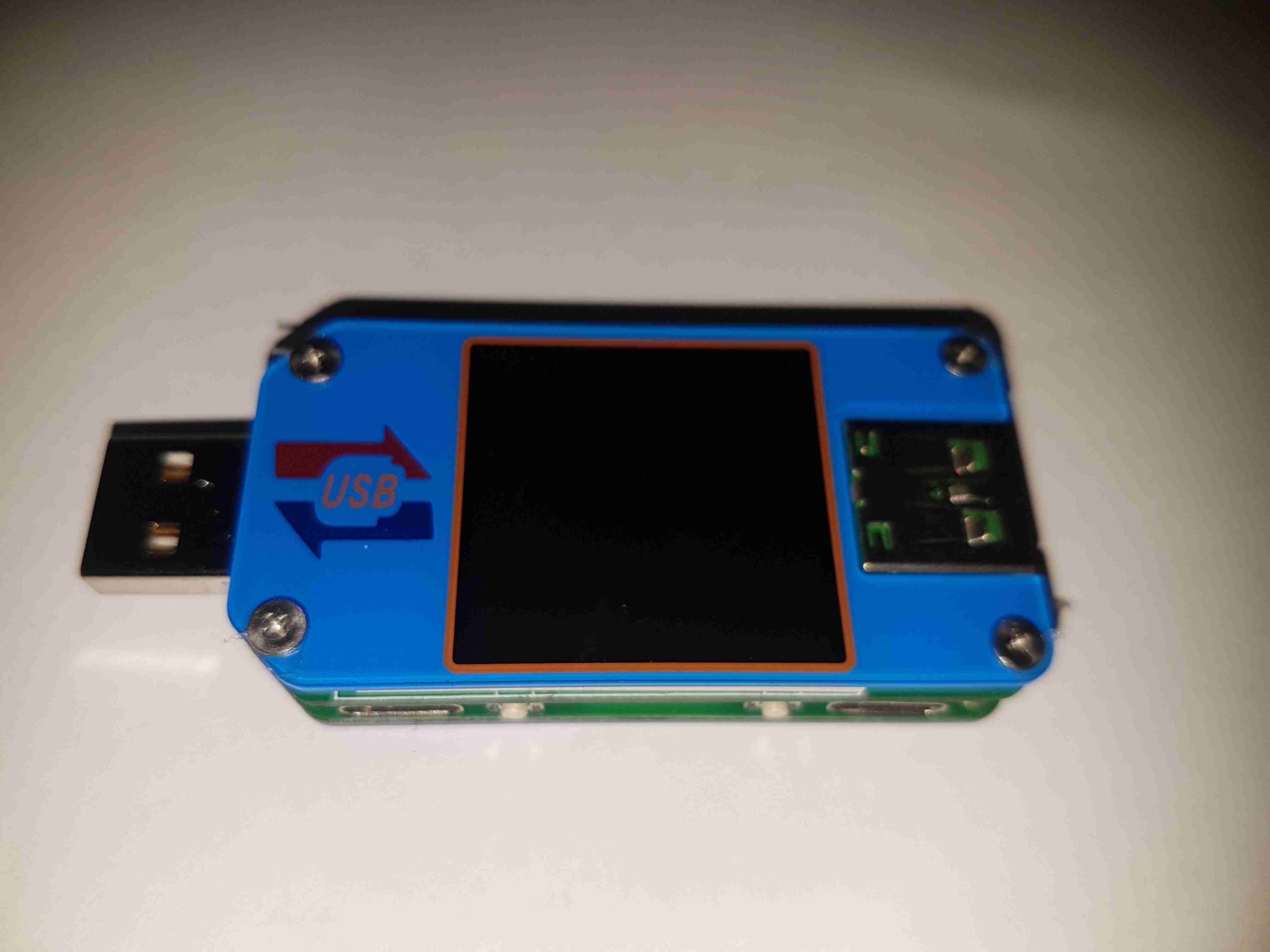
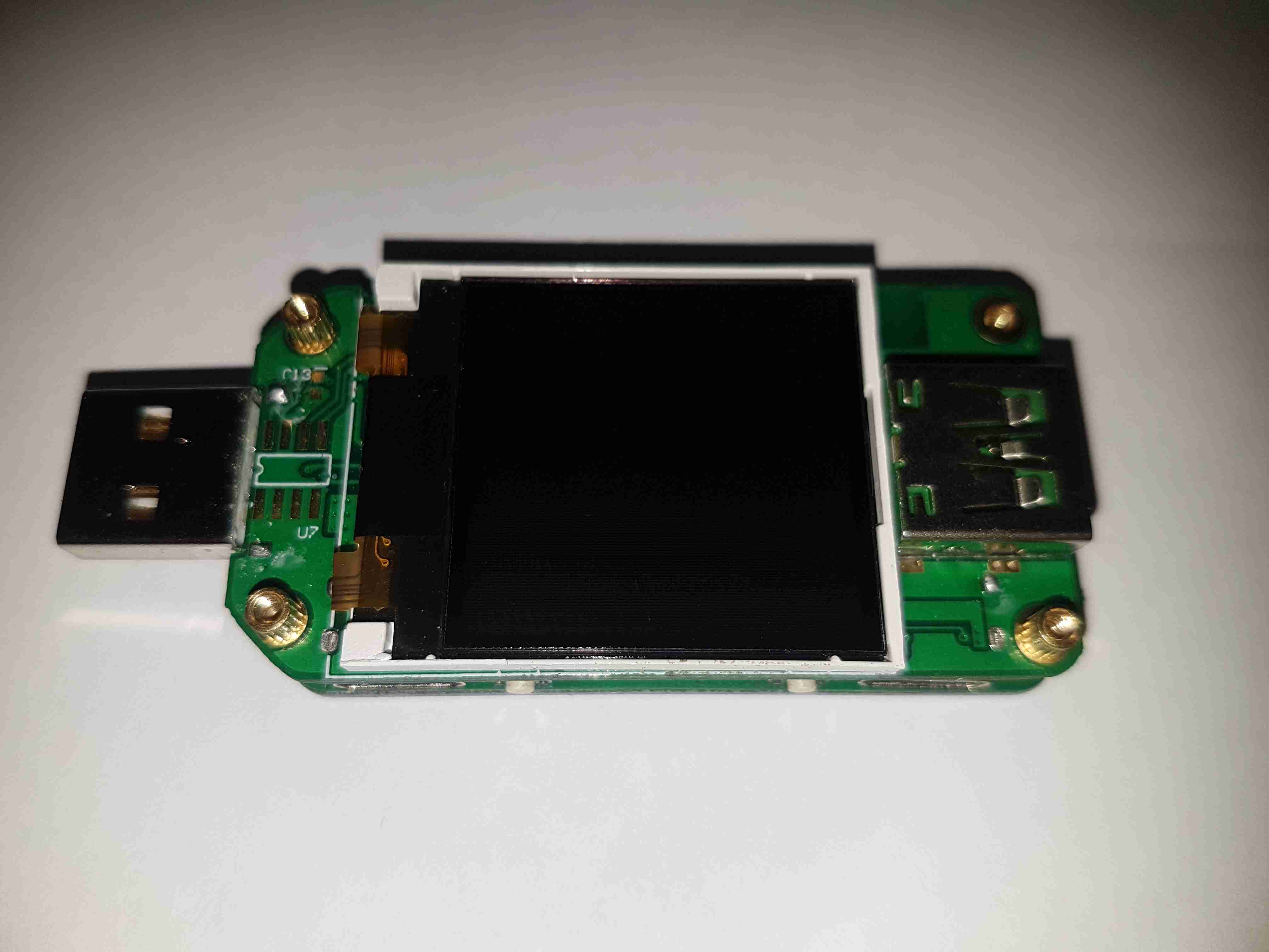
Here’s a nice little feature-packed USB power meter, the UM25C. This unit has USB-C along with the usual USB type A connectors, along with a bluetooth radio for remote monitoring of stats via a Windows or Android app. Construction is nice, it’s a stack of two PCBs, and polycarbonate cover plates, secured together with brass posts & screws.
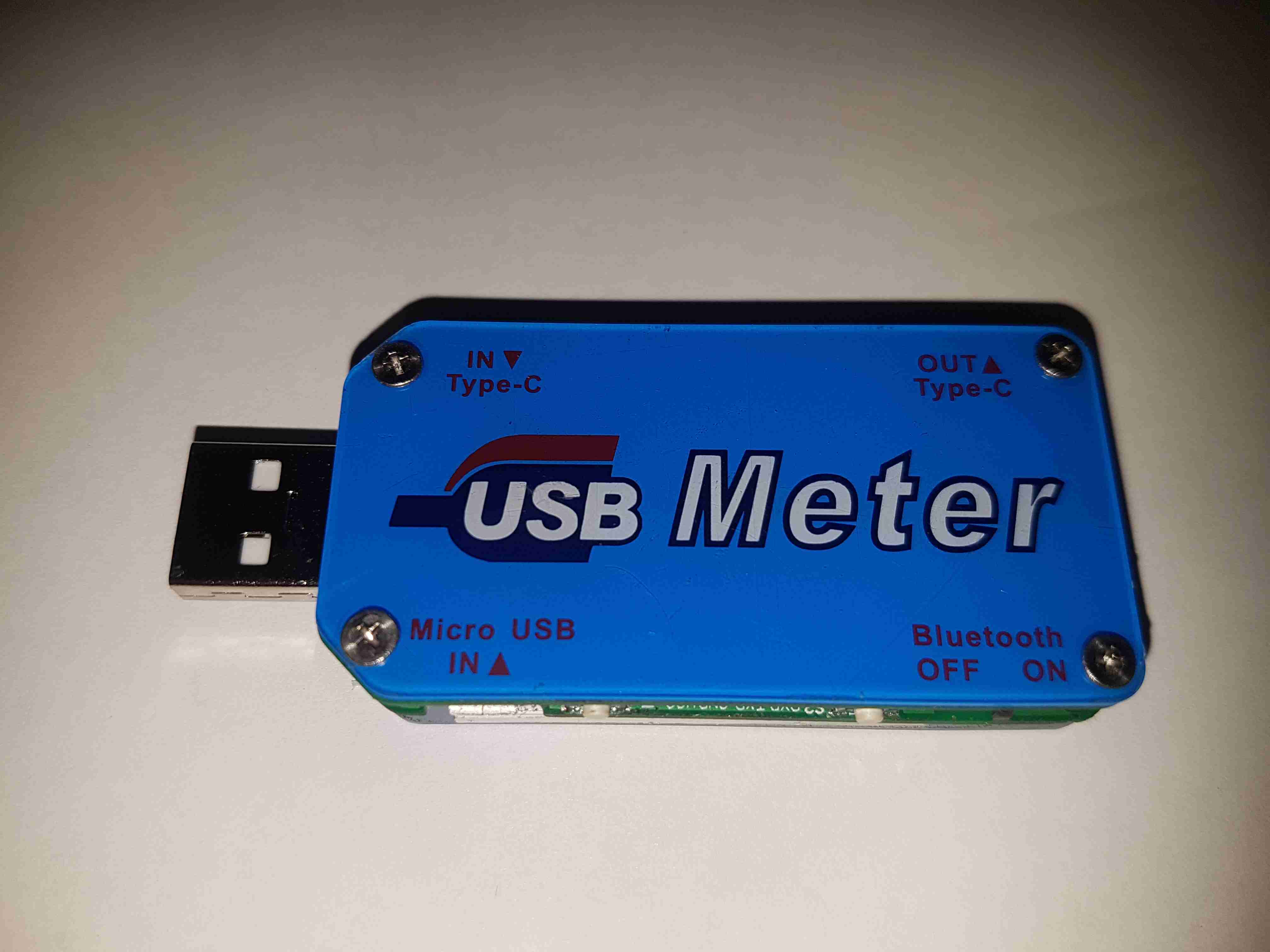
Back Cover
The back cover has the legend for all the side connectors, along with the logo.
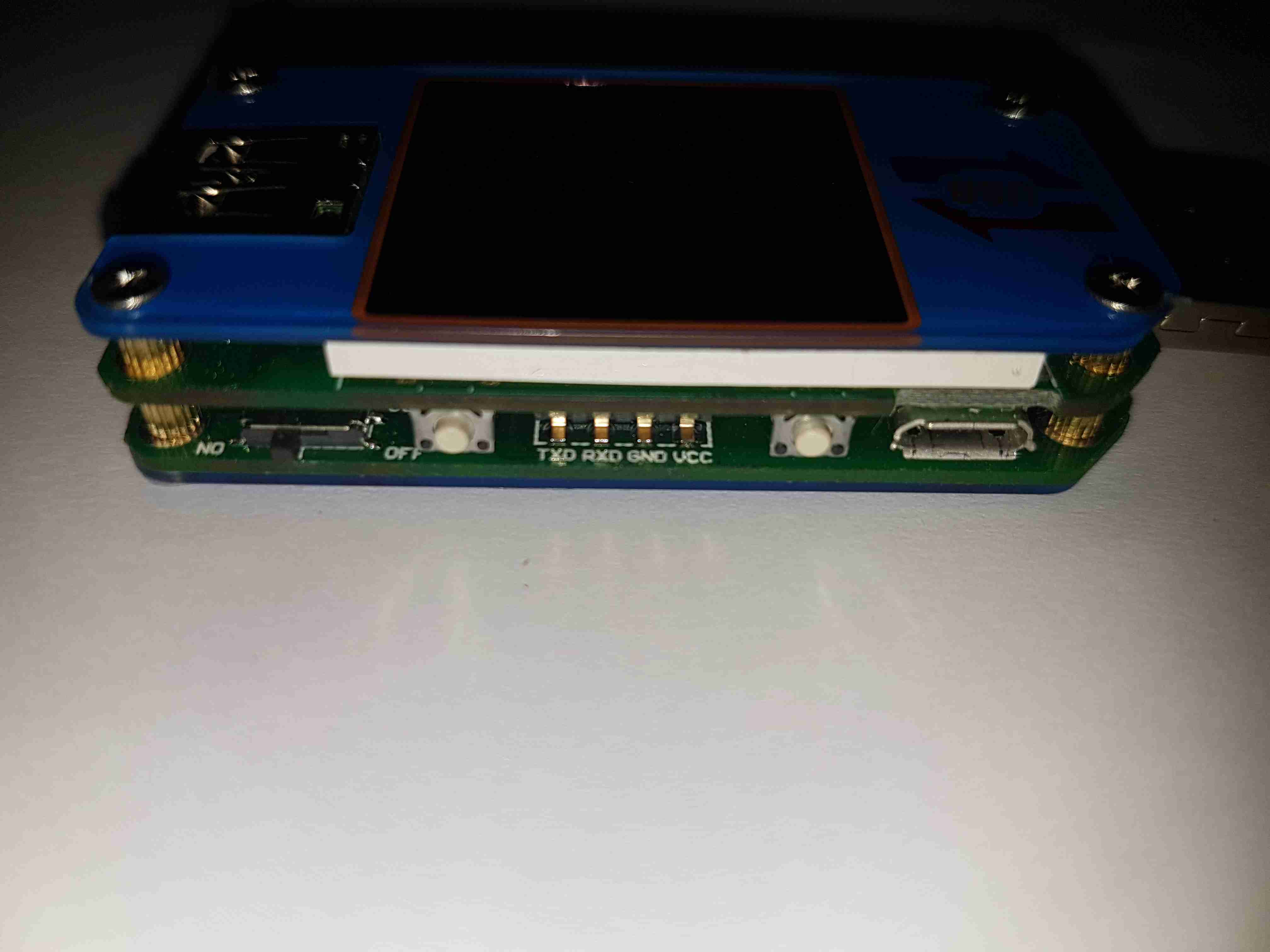
USB Micro Input
Down the sides are the user interface buttons, and here the Micro-B input connector. The 4-pin header is visible here that takes serial data down to the bluetooth section.
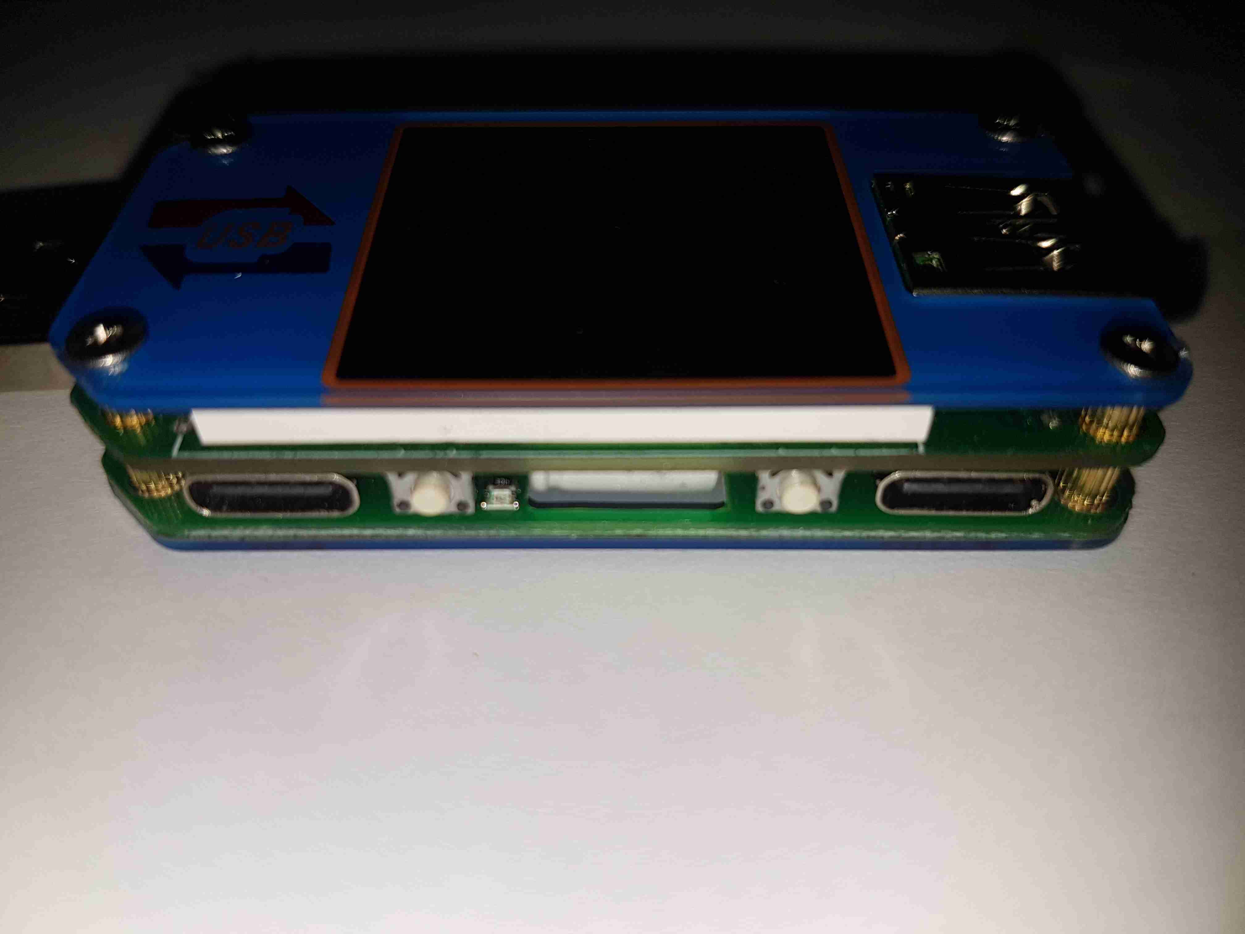
USB-C Connectors
The other side has the remaining pair of buttons, and the USB-C I/O. I don’t yet own anything USB-C based, but this is good future proofing.
LCD Display
Removing the top plastic cover plate reveals the small 1″ TFT LCD module. This will be hot-bar soldered underneath the screen. There’s an unused footprint next to the USB input connector, judging by the pin layout it’s probably for a I²C EEPROM.
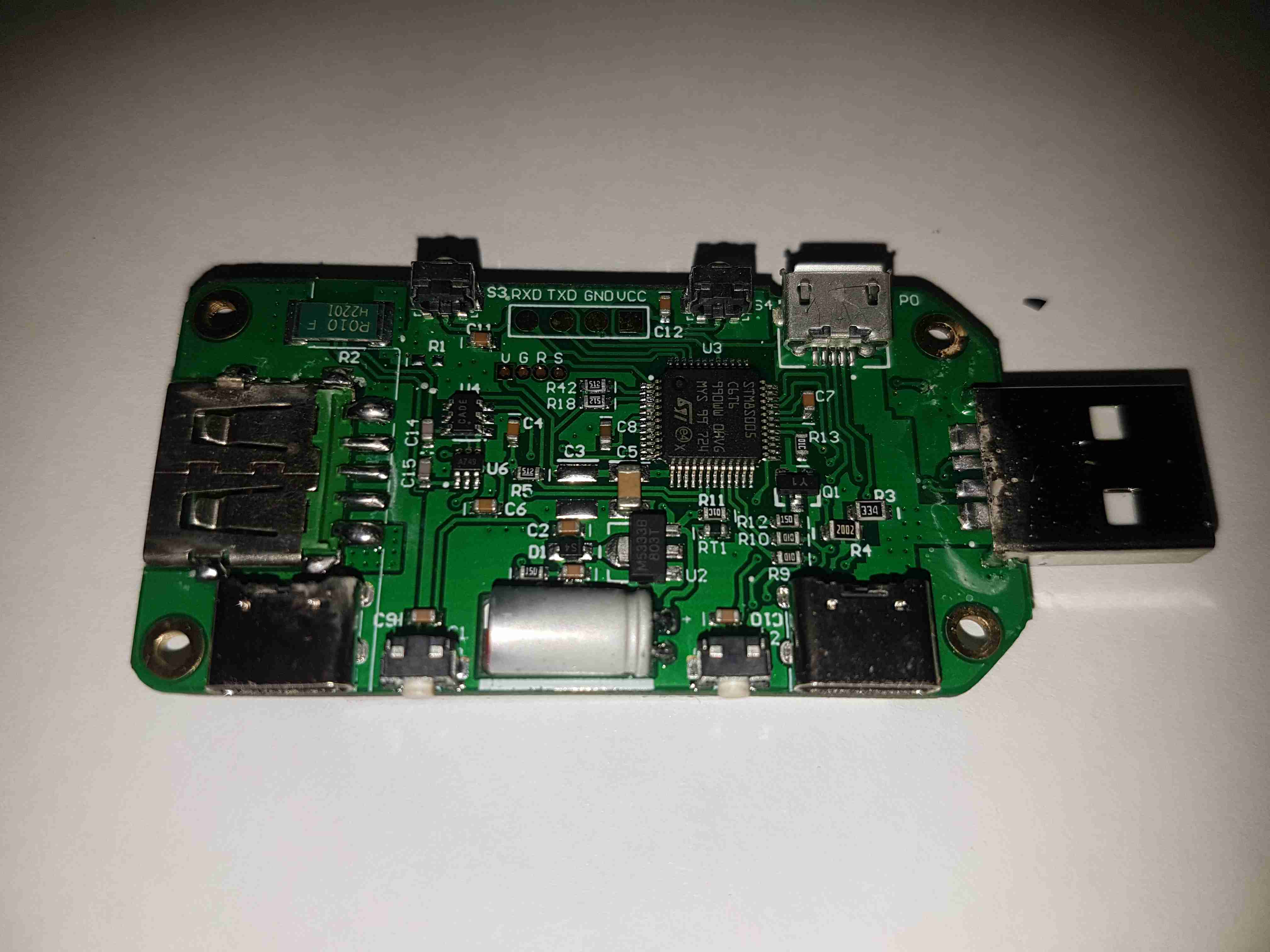
Main Board Components
The underside of the top PCB has all the main components. The brains of the operation is a ST STM8S005C6T6 microcontroller. It’s at the basic end of the STM range, with a 16MHz clock, 32K flash, EEPROM, 10-bit ADC, SPI, UART & I²C. The main 0.010Ω current shunt is placed at the top left of the board in the negative rail. A couple of SOT-23 components in the centre of the board, I haven’t been able to identify properly, but I think they may be MOSFETs. The large electrolytic filter capacitor has a slot routed into the PCB to allow it to be laid flat. Providing the main power rail is a SOT-89 M5333B 3.3v LDO regulator.
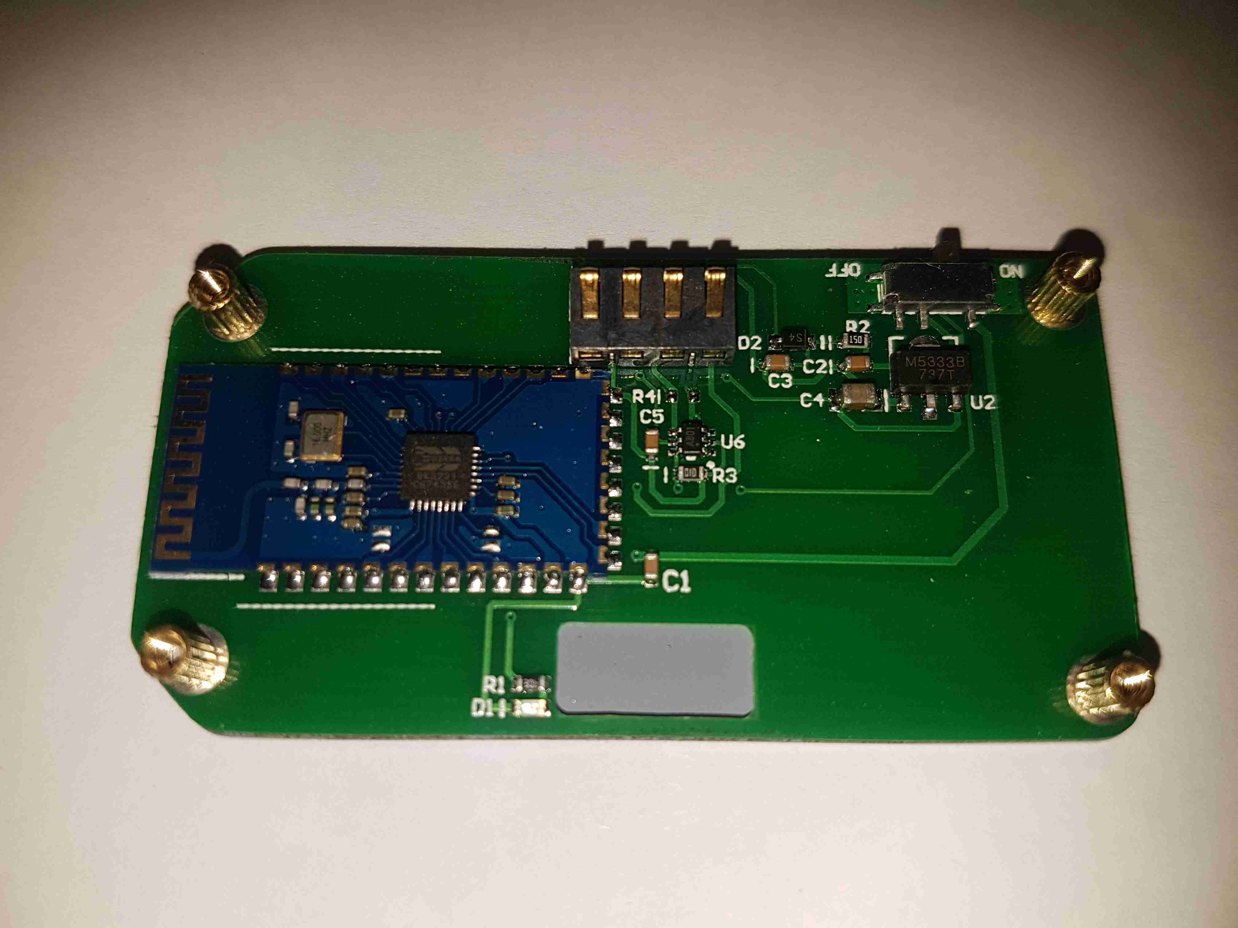
Bluetooth Radio
The bottom board contains the bluetooth radio module, this is a BK3231 Bluetooth HID SoC. The only profile advertised by this unit is a serial port. There’s a local 3.3v LDO regulator & support components, along with an indicator LED.
Since I do festivals every year, along with a couple of other camping trips if the weather is good enough, I’ve been taking equipment with me for years in flight cases to make things more comfortable. Things like a large battery to power lights & device charging, an old Eberspacher diesel heater for the times when the weather isn’t great, and an inverter to run the pumps built into airbeds.
Red Diesel / Heating Oil is my fuel of choice for camping purposes, as it’s about the safest fuel around, unlike Butane/LPG it is not explosive, will not burn very readily unless it’s atomized properly & it’s very cheap. Paraffin is an alternative fuel, but it’s expensive in the UK, at about £12 per 5L.
The Hexamine-based tablet fuels the UK festivals promote is nasty stuff, and the resulting combustion products are nastier still. (Things like Hydrogen Cyanide, Formaldehyde, Ammonia, NOX). They also leave a sticky black grok on every cooking pot that’s damn near impossible to remove. Meths / Trangia stoves are perfectly usable, but the flame is totally invisible, and the flammability of alcohol has always made me nervous when you’ve got a small pot of the stuff boiling while it’s in operation in the middle of a campsite filled with sloshed festival goers. A single well-placed kick could start a massive fire.
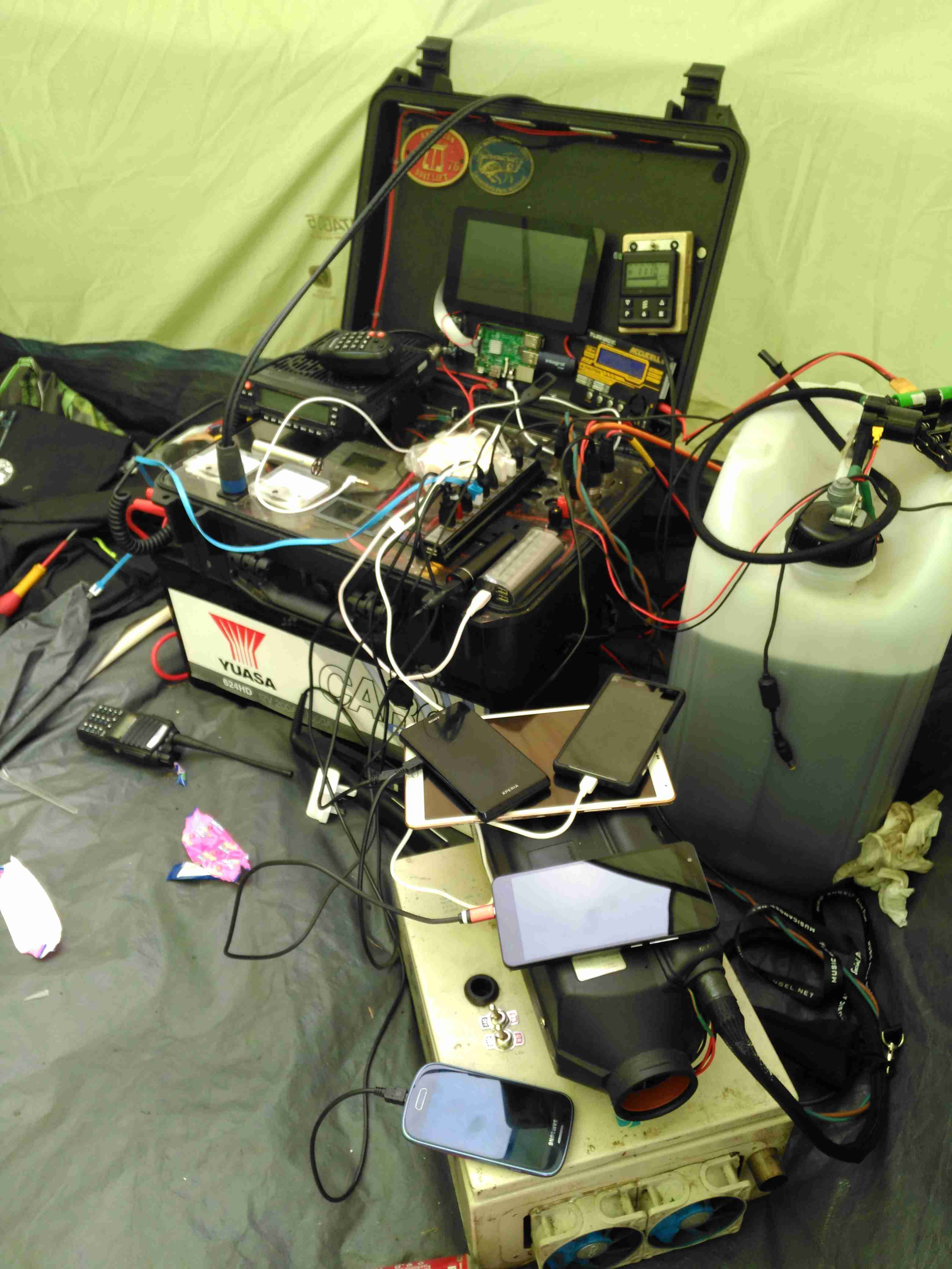
Previous System
Over the years the gear has evolved and grown in size, so I decided building everything into one unit on wheels would be the best way forward. I’ve been working on this for some time, so it’s time to get some of the details on the blog! Above you can see the system used for last year’s camping, the heater is separate, with a 25L drum of heating oil, the battery is underneath the flight case containing all the power components, and it’s currently charging All The Things.
Overview
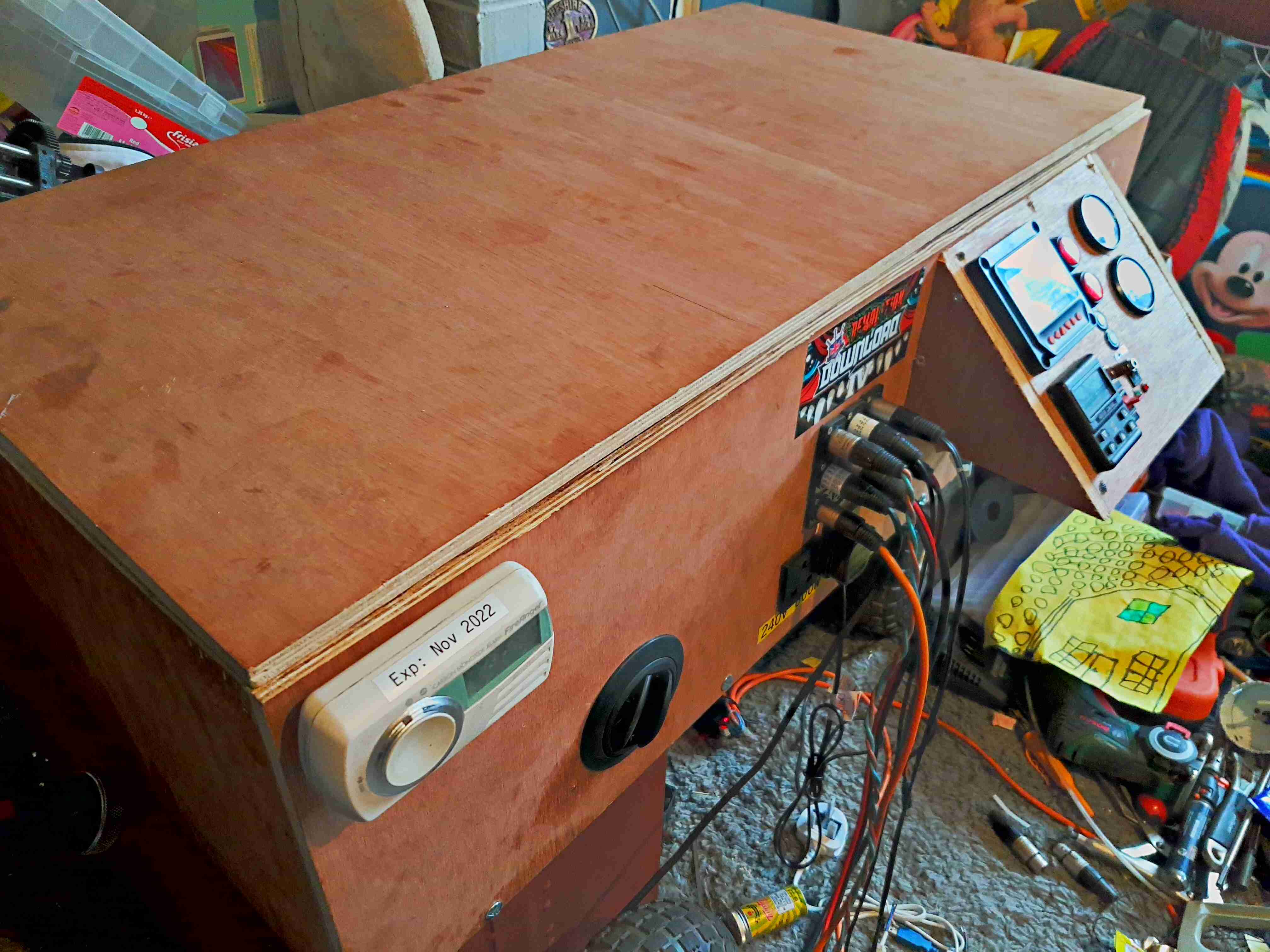
Above is the new unit almost finished, the bottom frame is a standard eBay-grade 4-wheel trolley with a few modifications of my own, with a new top box built from 12mm hardwood marine plywood. This top is secured in place with coach bolts through the 25mm angle iron of the trolley base. The essential carbon monoxide detector is fitted at the corner.
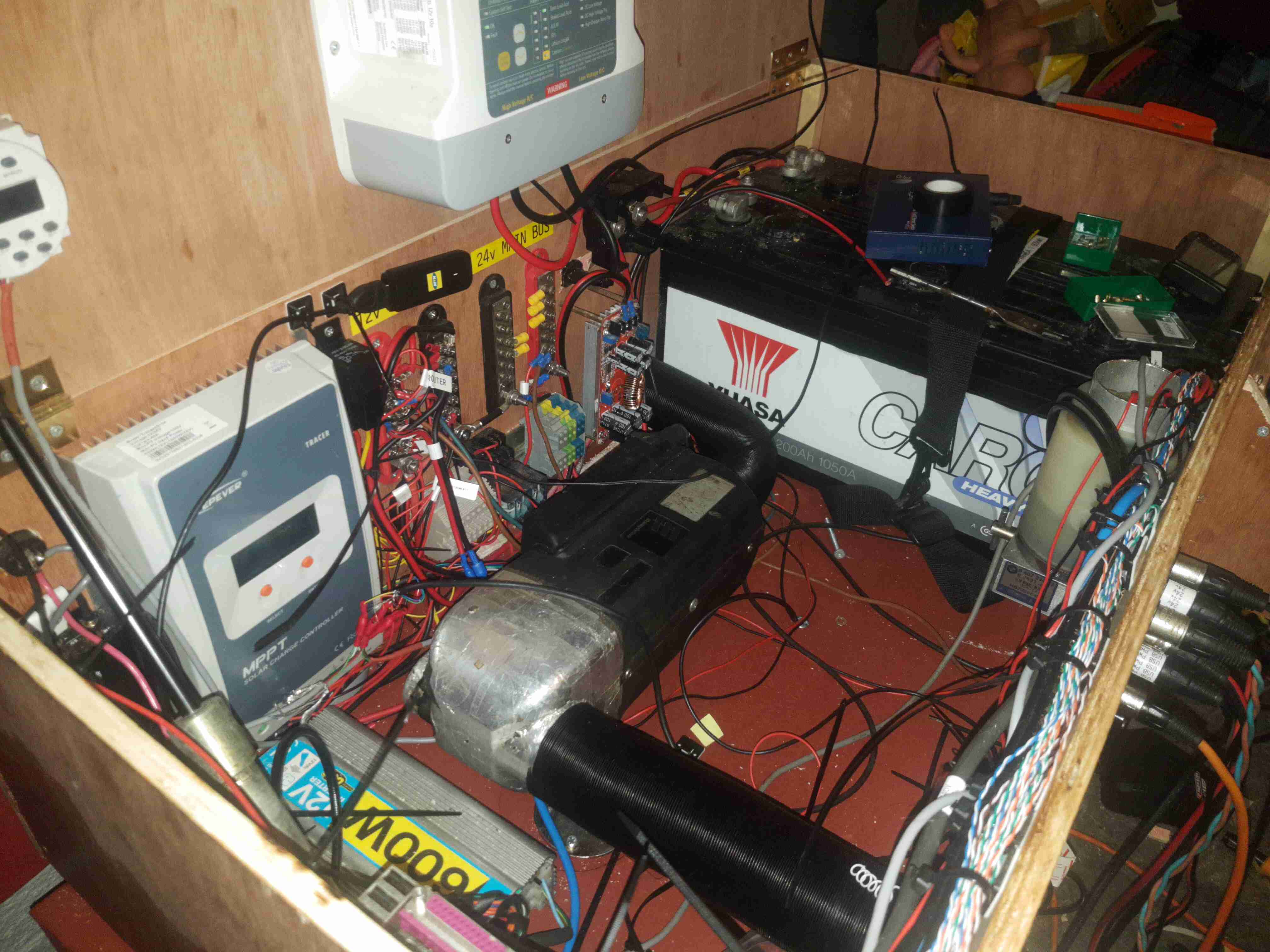
Internal View
The inside gets a bit busy with everything crammed in. The large Yuasa 200Ah lead-acid battery is at the far end, with it’s isolation switch. Right in the middle is the Eberspacher heater with it’s hot air ducting. I’ve fitted my usual 12/24v dual voltage system here, with the 24v rail generated from a large 1200W DC-DC converter.
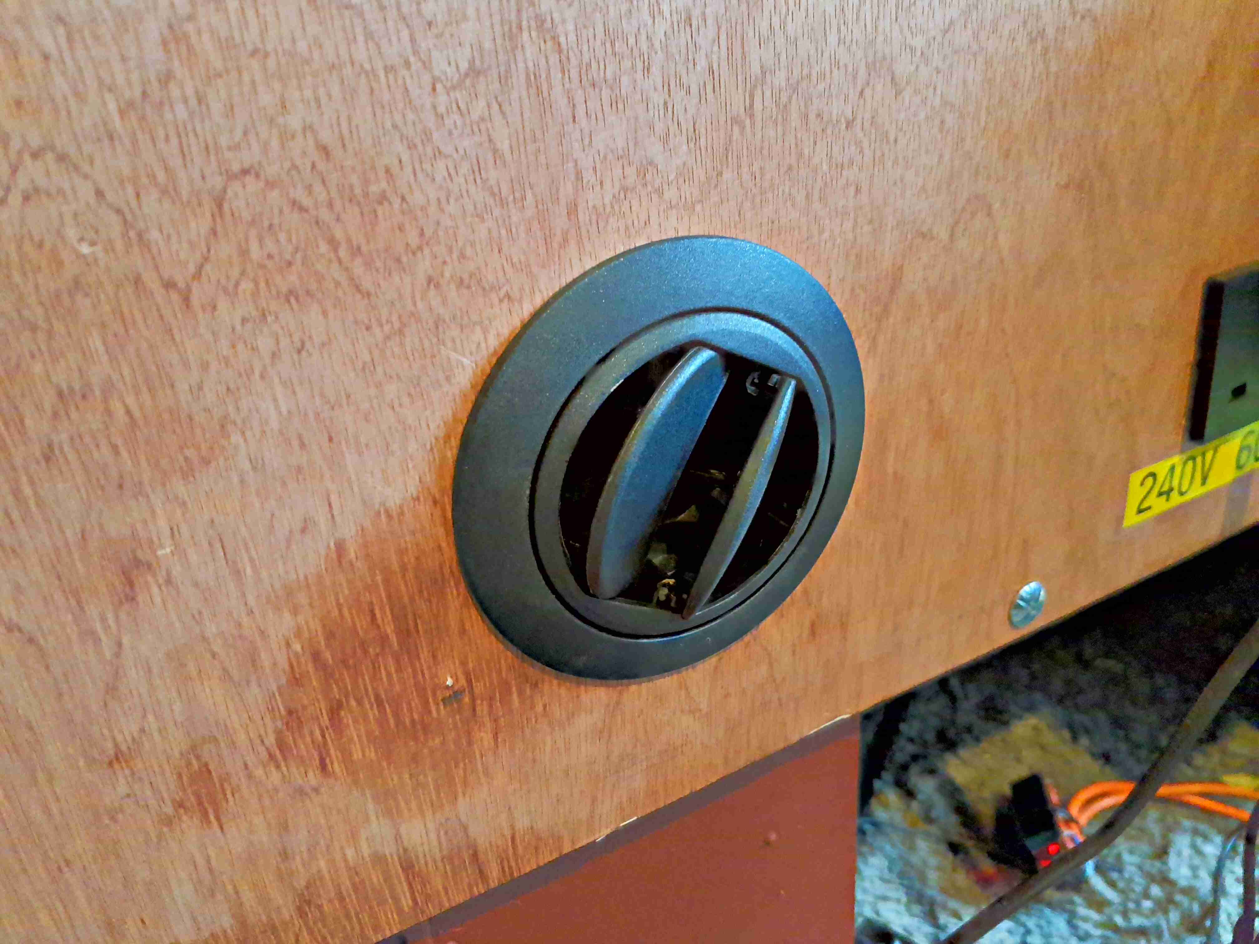
Heater Vent
The hot air duct for the heater is fed out through a standard vent in the front. Very handy for drying out after a wet day.
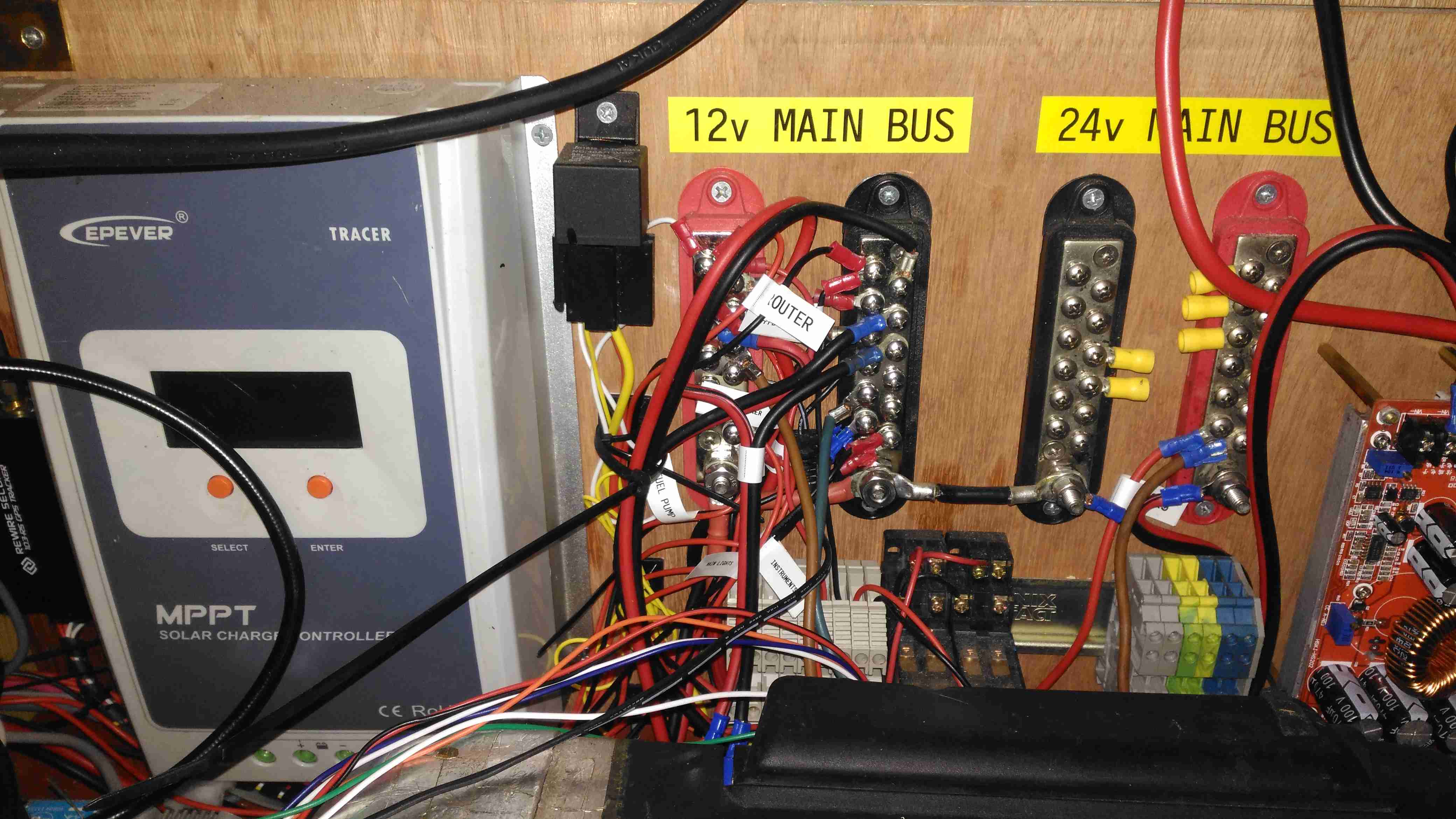
Main Bus Bars & Solar Controller
Here’s a closeup of the distribution bus bars, with both negative rails tied together in the centre to keep the positives as far away from each other as possible, to reduce the possibility of a short circuit between the two when working on the wiring. The EpEver Tracer 4210A MPPT Solar Charge Controller is on the left, tucked into the corner. This controller implements the main circuit protection for the battery, having a 40A limit. Individual circuits are separately fused where required. Solar input on this unit is going to be initially provided by a pair of 100W flexible panels in series for a 48v solar bus, the flexible panels are essential here as most of the festivals I attend do not allow glass of any kind onsite, not to mention the weight of rigid panels is a pain.
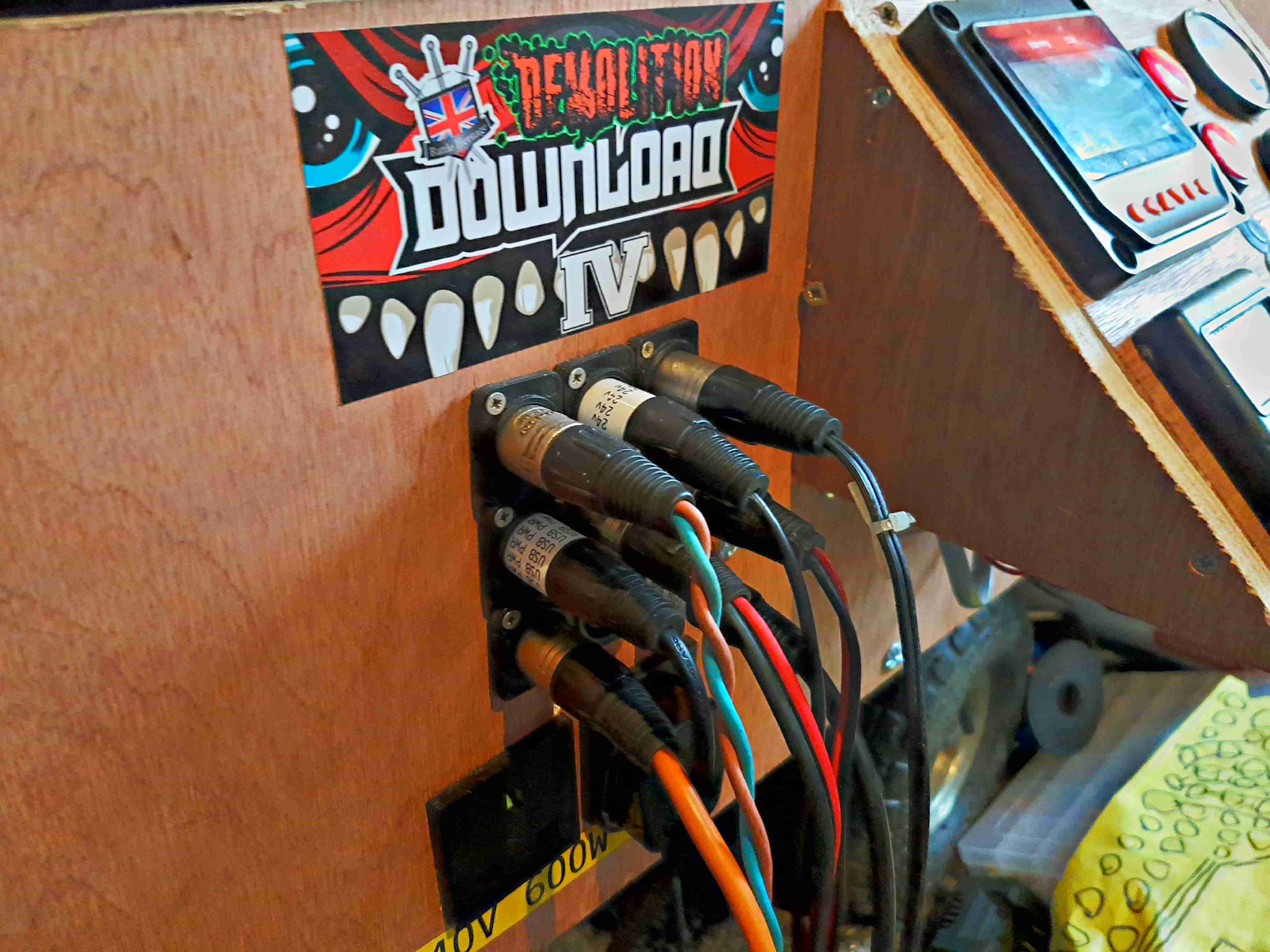
DC Output Sockets
I’ve stuck with the 3-pin XLR plugs for power in this design, giving both the 12v rail, 24v rail & ground.
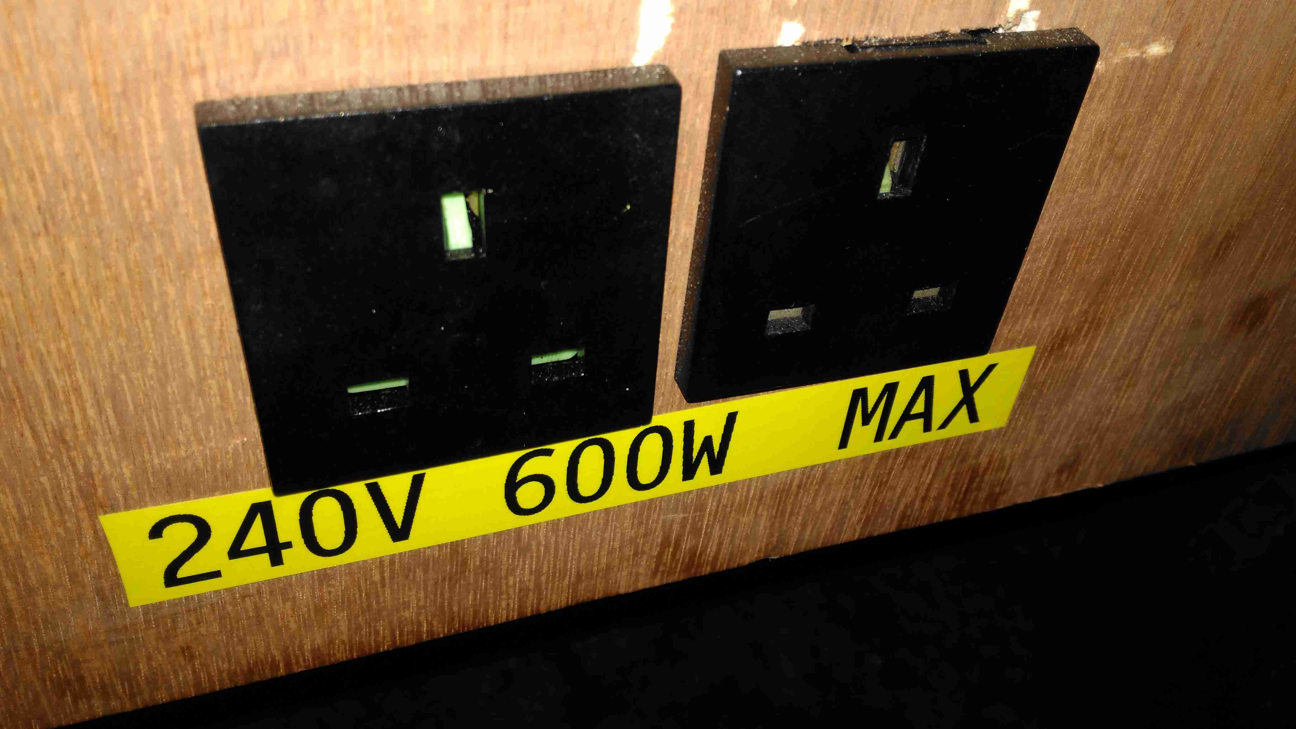
Inverter Outputs
Tucked under the DC outputs are a pair of panel sockets for the 600W inverter. This cheapo Maplin unit is only usually used to pump up air beds, so I’m not expecting anyone to pull anything near max output, but a warning label always helps.
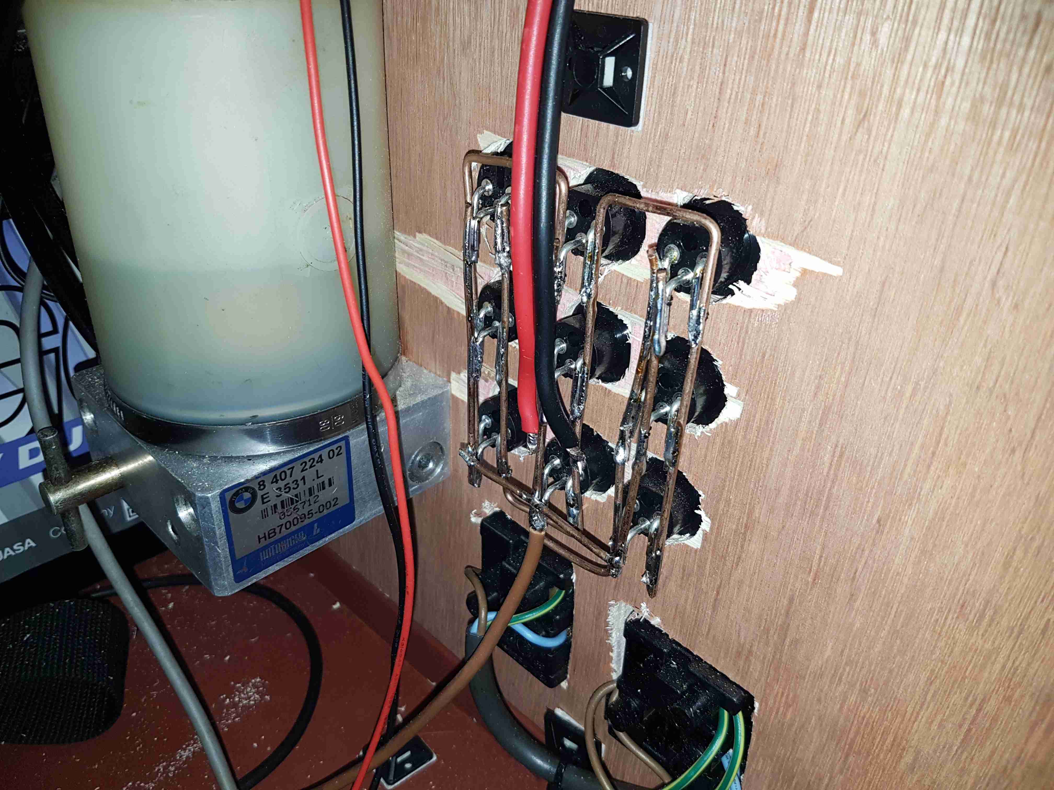
Power Socket Wiring
Behind the front panel is the hardwiring for the power sockets. The DC jacks are connected together using 2mm solid copper wire, bent into bus bars.The mains wiring underneath is a simple radial circuit straight from the inverter. The large cylinder on the left is a hydraulic pump from a BMW Z3, which runs a hydraulic cylinder for lifting the lid of the top box, used simply because I had one in the box of junk.
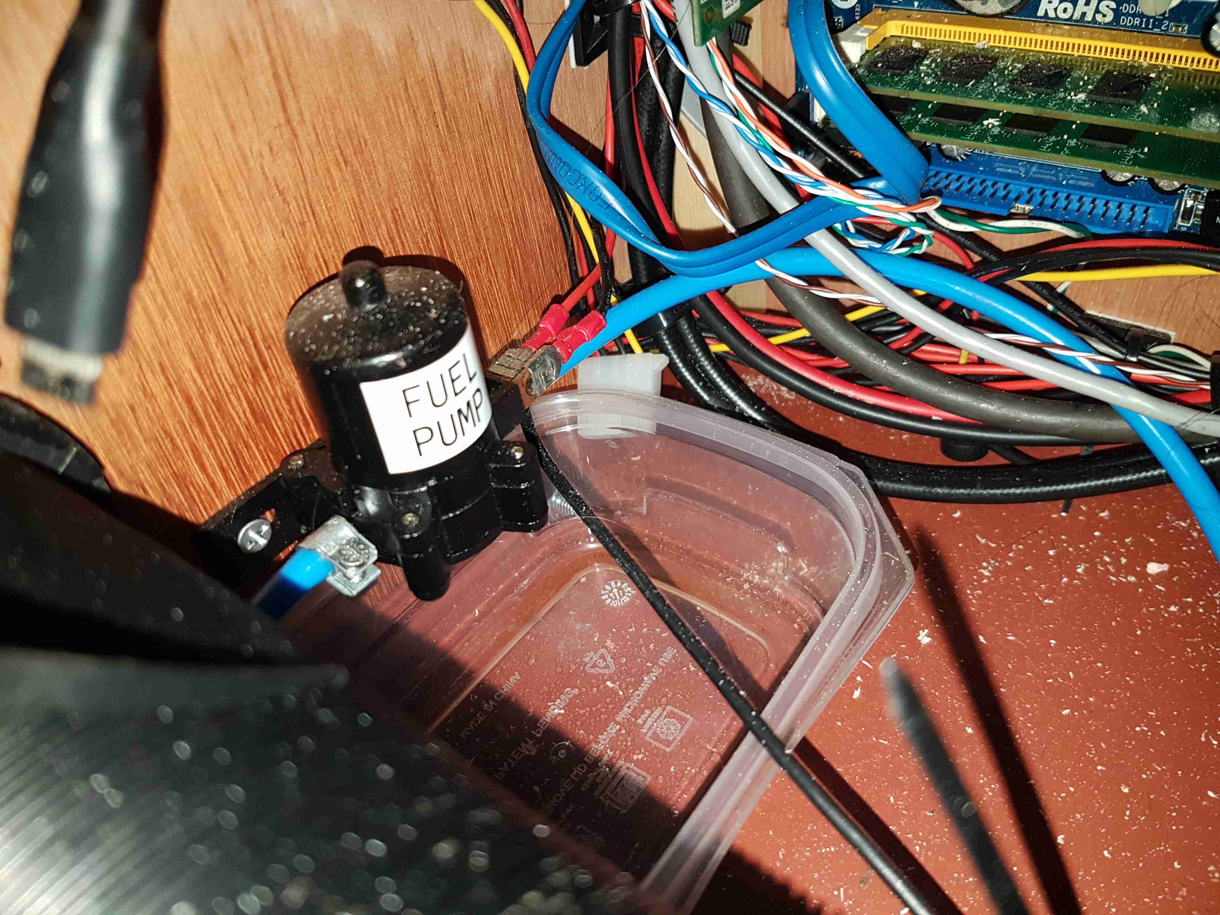
Fuel Pump
External fuelling is dealt with by a small gear pump, this is used to fuel up the Optimus Stove & Petromax Lantern. This is in fact a car windscreen wash pump, but it has coped well with pumping hydrocarbons, it currently has a small leak on the hose connections, but the seals are still entirely intact.
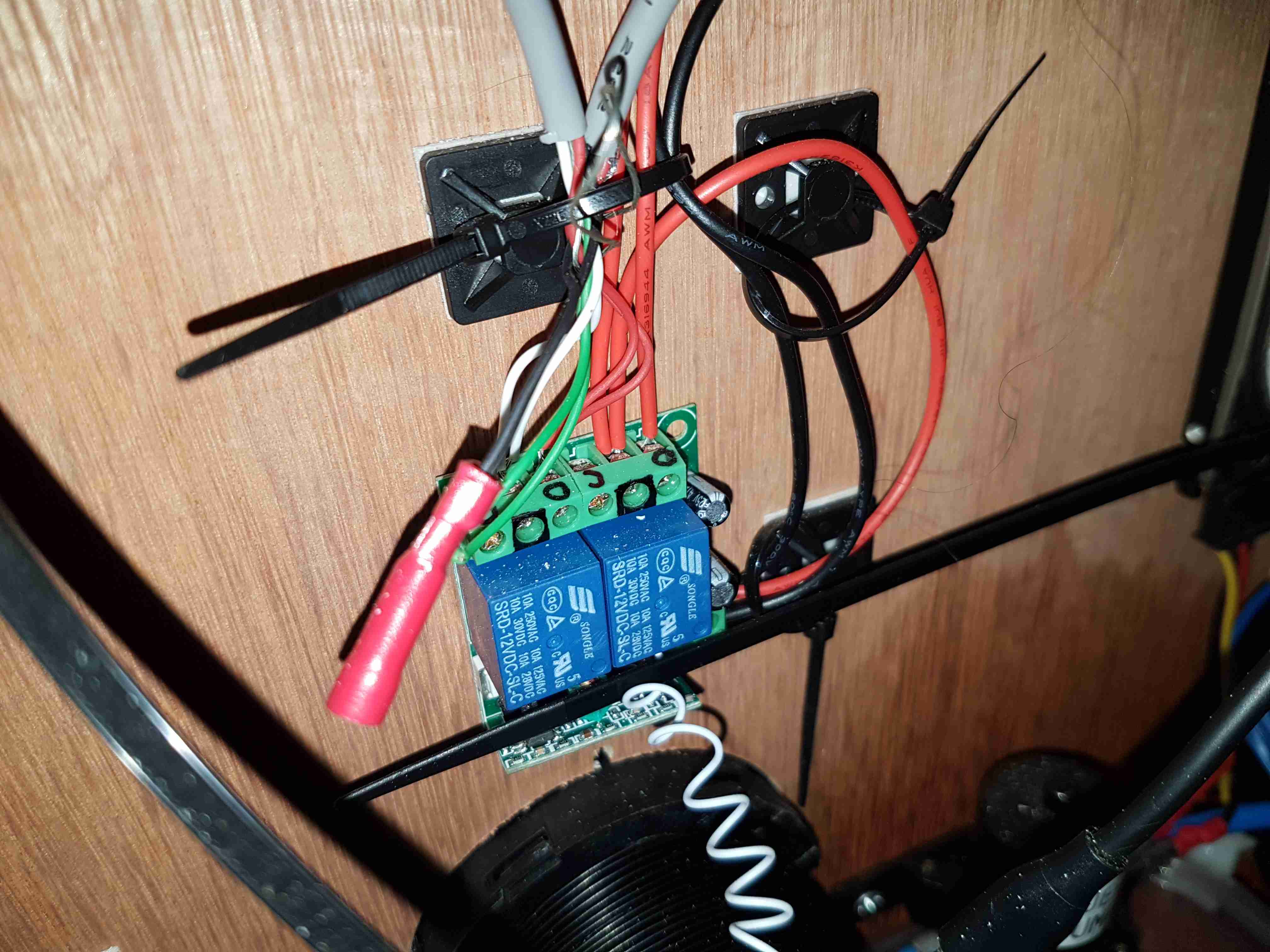
Remote Relays
There’s a small remote relay module here, for switching the DC output for lighting & the heater from afar. Very useful when it’s dark, since there’s no need to fumble around looking for a light switch. A car-style fob on my keyring instead.
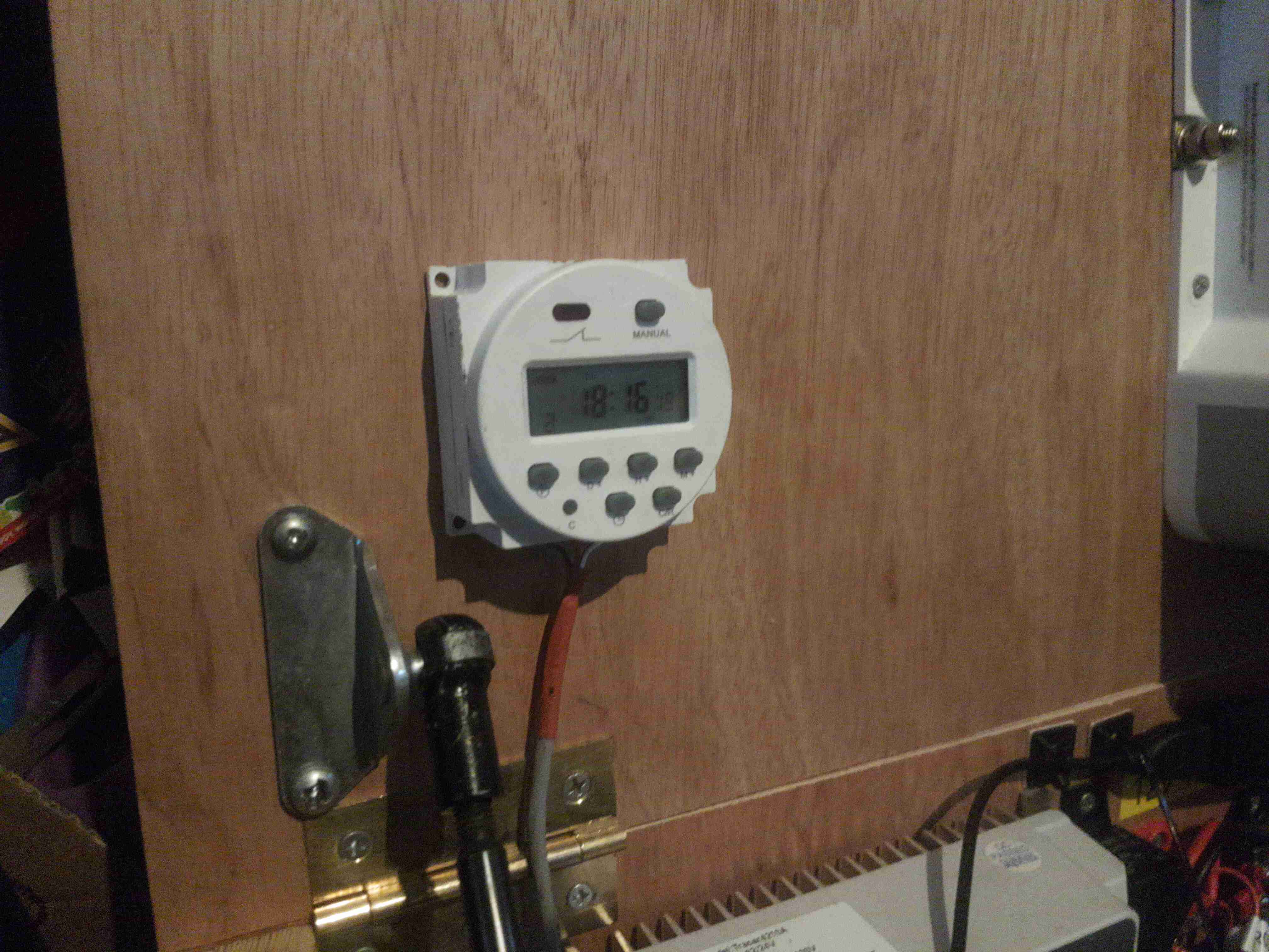
Heater Timer
Since the Eberspacher 701 controller I have is an ex-BT version, it’s very limited in it’s on time, a separate timeswitch is fitted to control the heater automatically. Being able to return to a nice warm tent is always a bonus.
Just to the left can be seen the top ball joint for the hydraulic cylinder that lifts the top of the box.
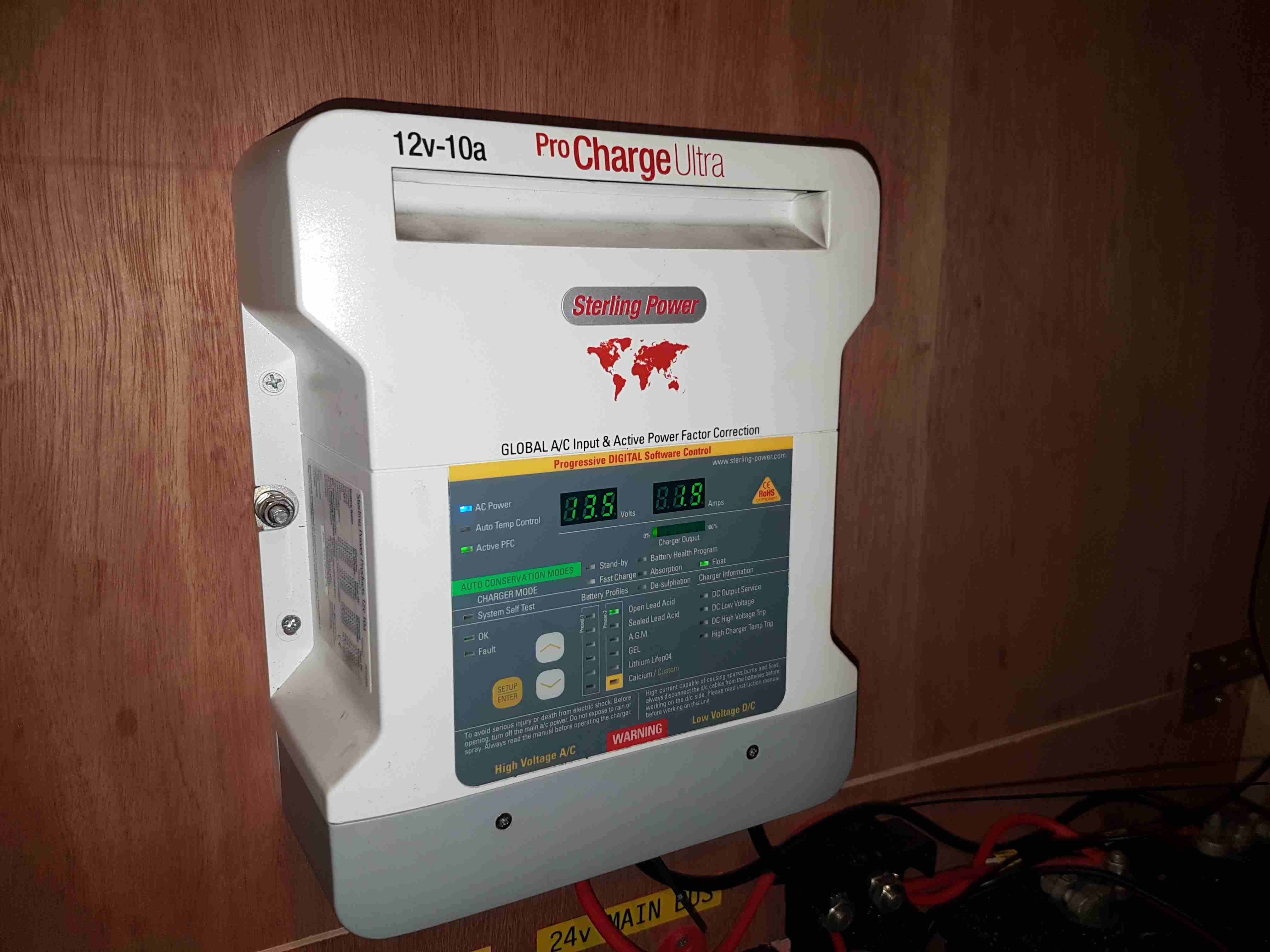
Battery Charger
The final large component is the battery charger. This unit will maintain the battery when the trolley isn’t being used.
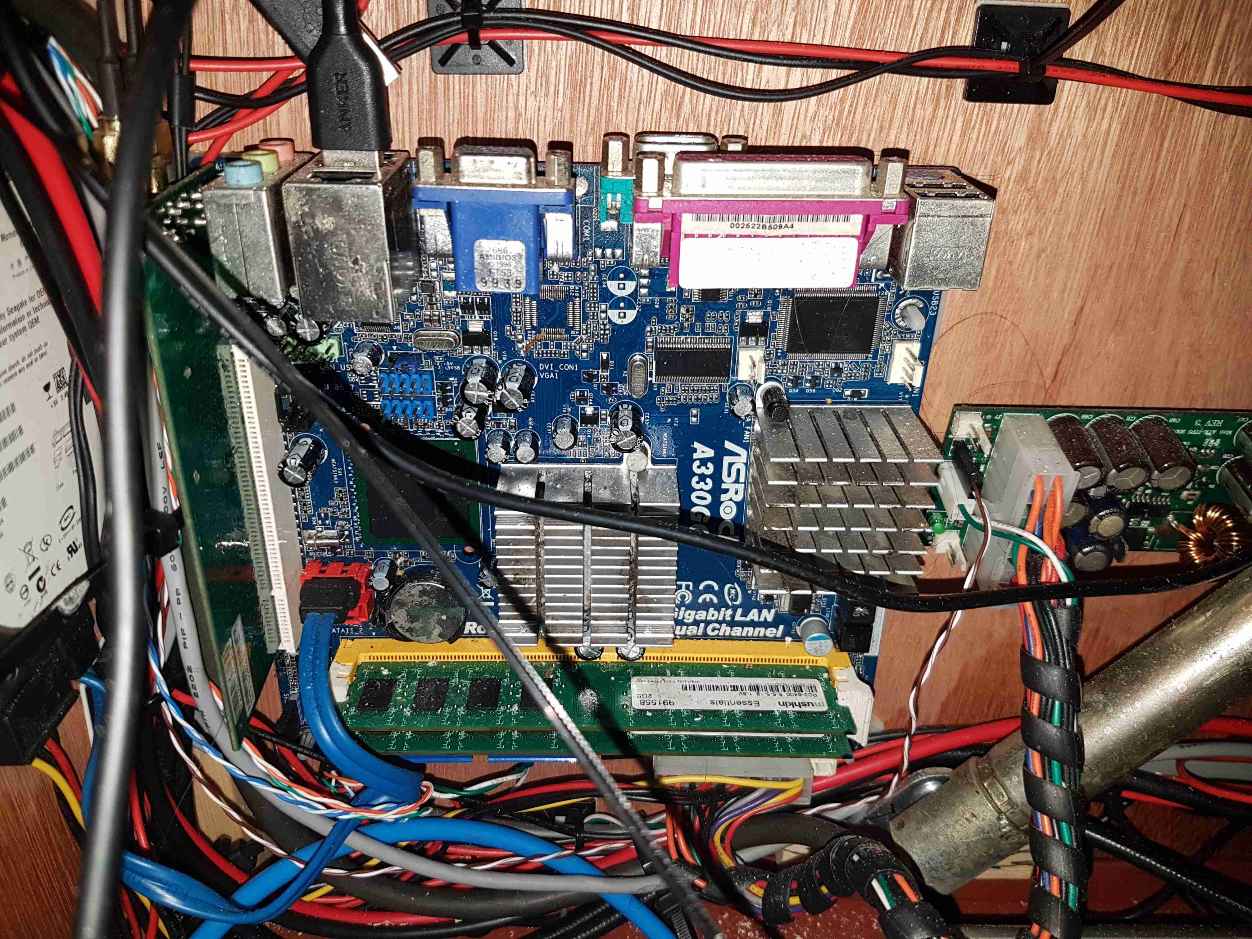
Router Motherboard
On the left side is the old Atom motherbaord used to provide a 4G router system. This unit gets it’s internet feed from a UMTS dongle & provides a local WiFi network for high speed connectivity. The bottom of the hydraulic cylinder is visible in the bottom right corner.
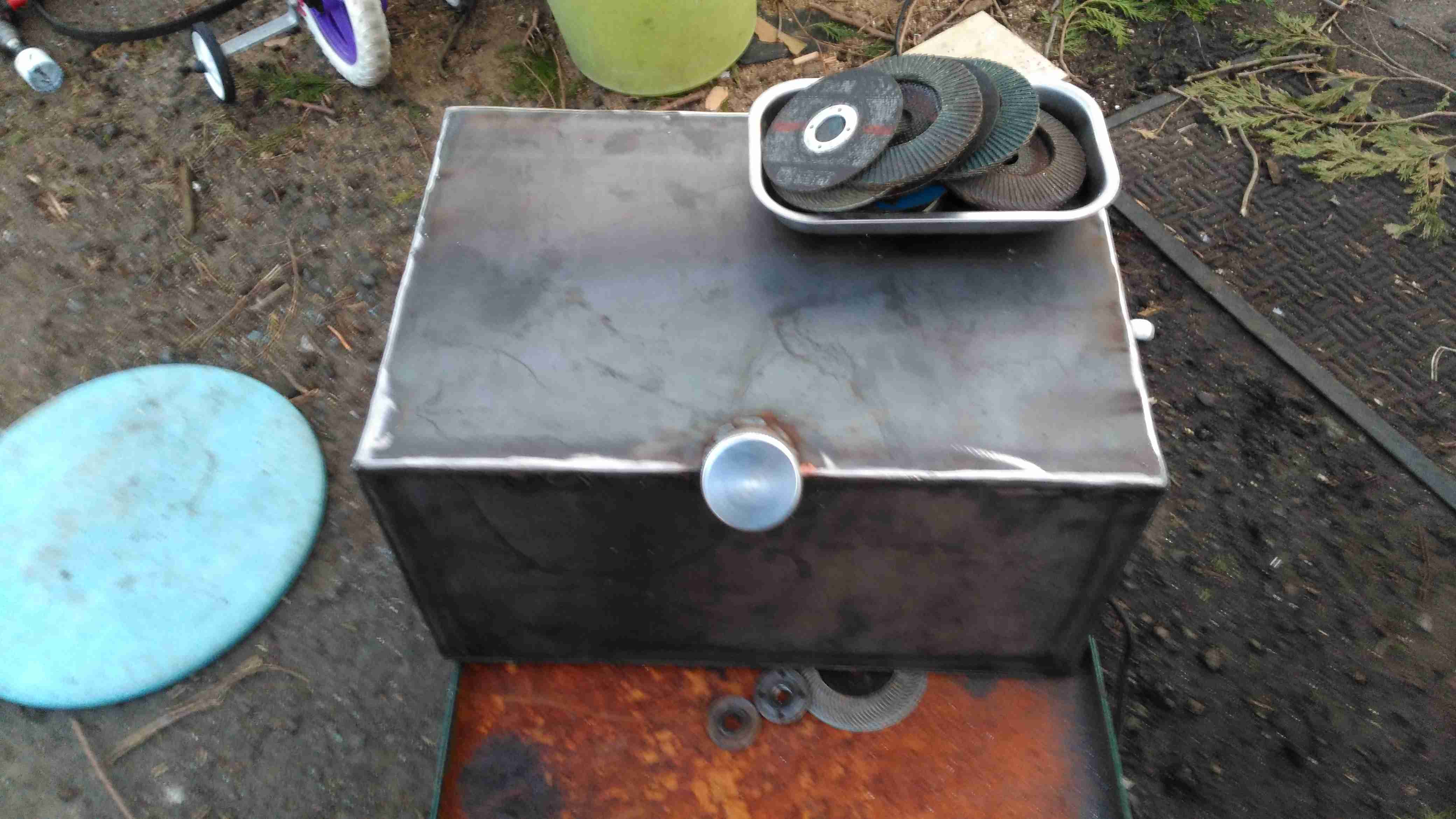
Fuel Tank Completed
Since the Eberspacher obviously needs fuel, a tank was required. In previous years I’ve used jerry cans for this purpose, but this trolley is supposed to have everything onboard, for less setup time. The tank is constructed from 3mm steel plate, MIG welded together at the seams to create a ~40L capacity. The filler neck is an eBay purchase in Stainless Steel. No photos of the tank being welded together, as I was aiming to beat sunset & it’s very difficult to operate a camera with welding gauntlets on 😉
The tank is the same width as the trolley frame, so some modification was required, having the wheels welded directly to the sides of the tank. This makes the track wider at the rear, increasing stability.
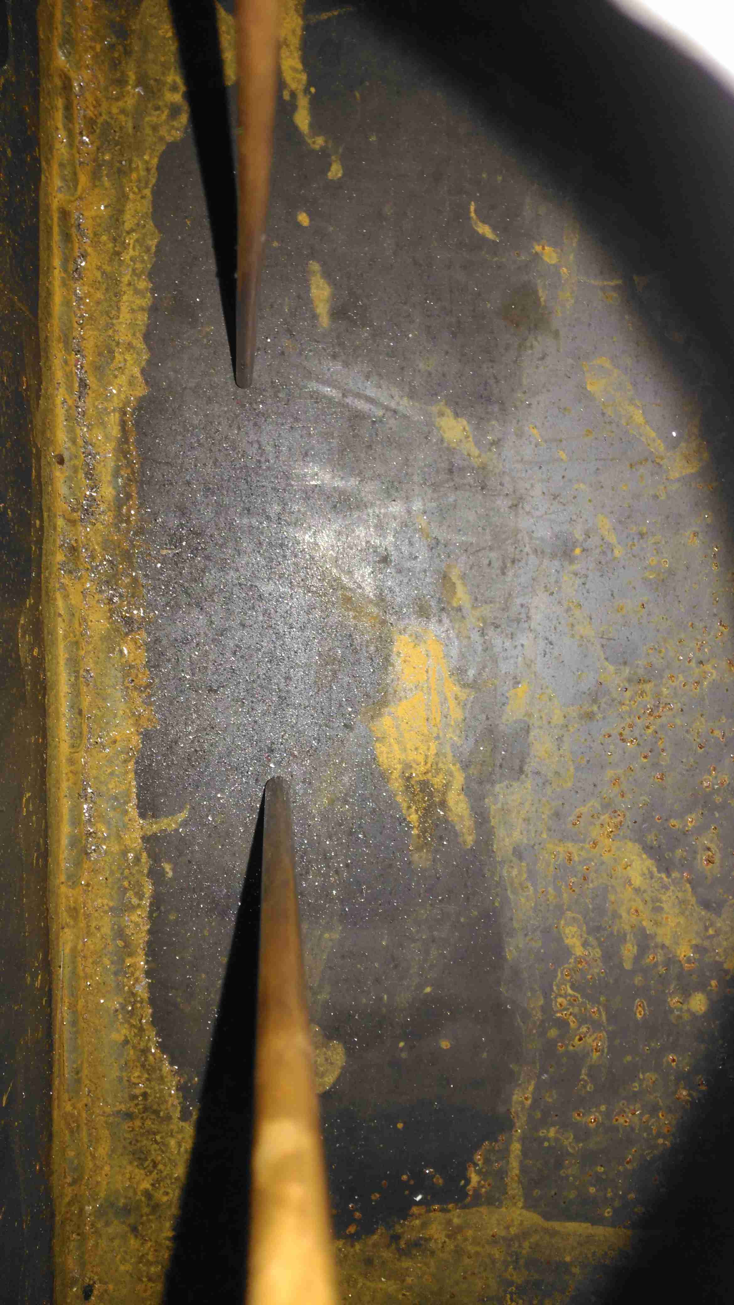
Fuel Dip Tubes
A quick view inside the tank through the level sender port shows the copper dip tubes for fuel supply to the heater, and an external fuel hose for my other fuel-powered camping gear. These tubes stop about 10mm from the bottom of the tank to stop any moisture or dirt from being drawn into the pumps.
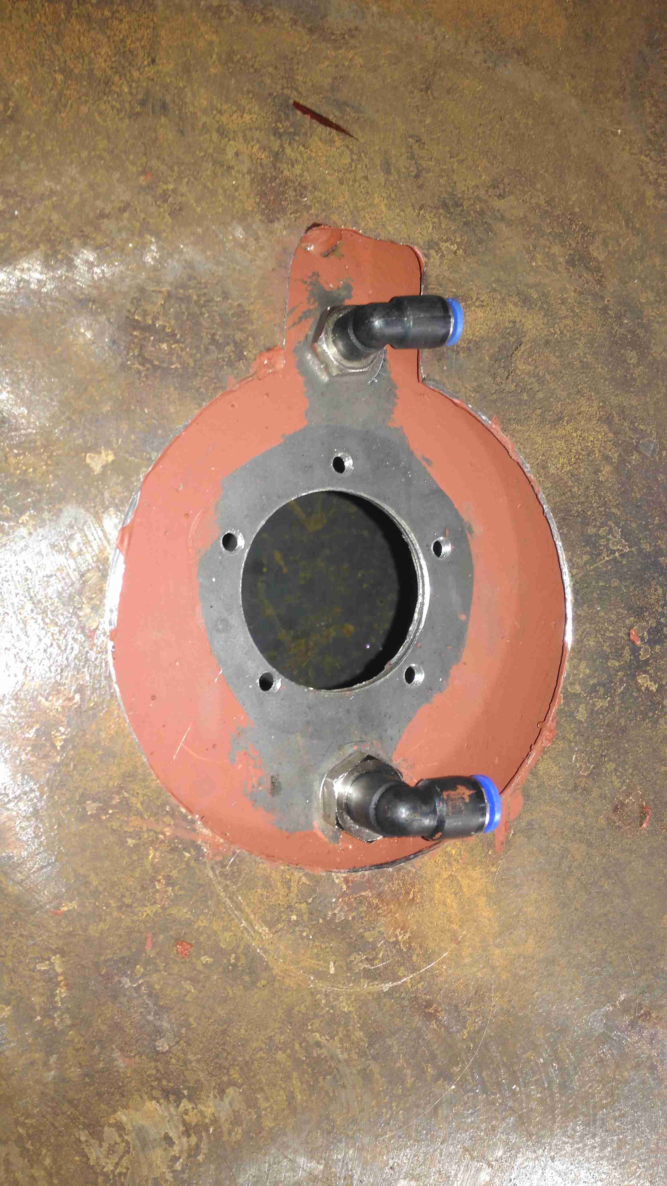
Fuel Feeds & Level Sender Port
The top of the tank is drilled for the fuel fittings & the level sender and has already been painted here. The 1mm base plate has yet to be painted.
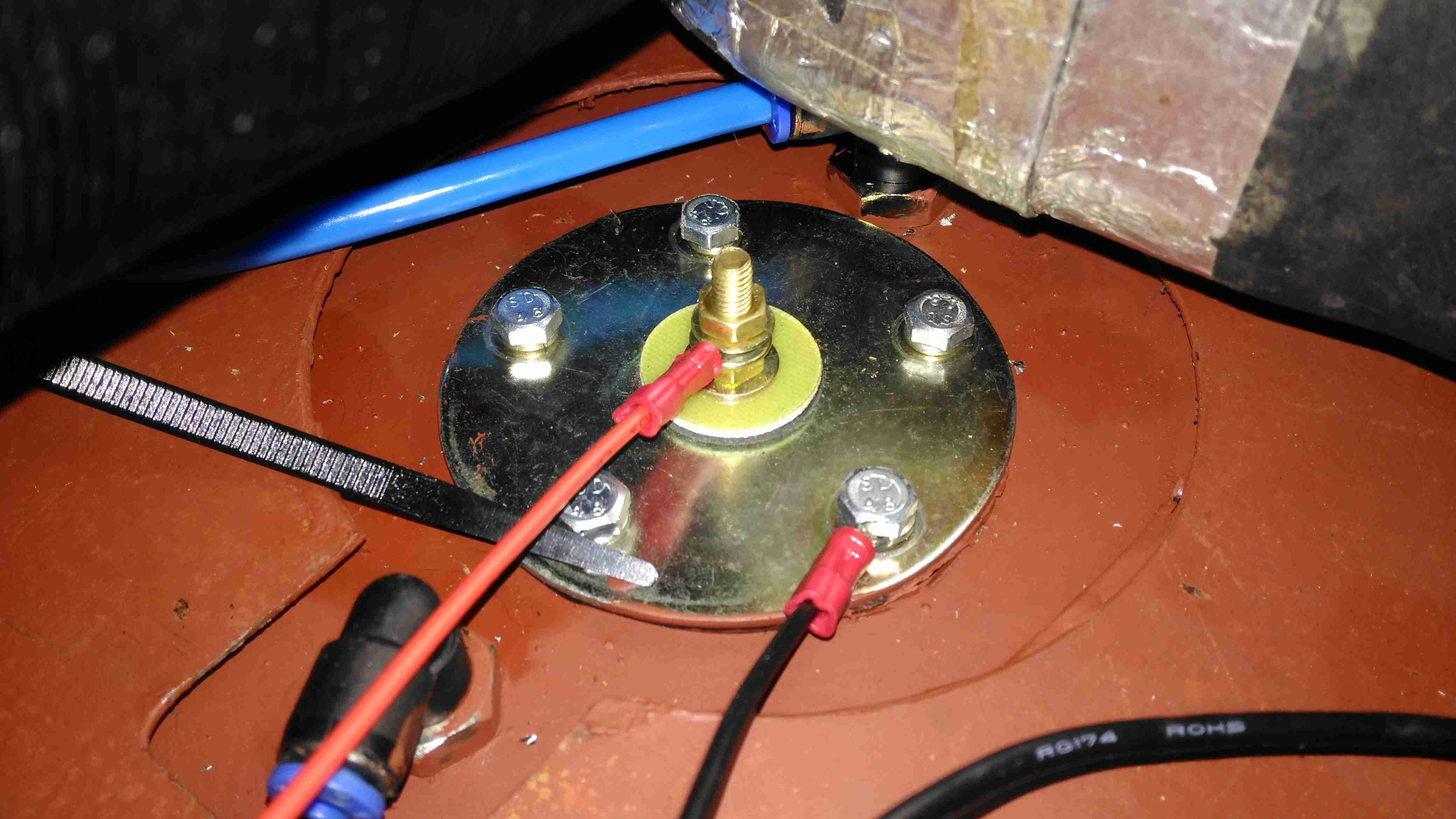
Level Sender Installed
Touching up the paint & fitting the sender is the last job for this part. The mesh bottom of the trolley has been replaced by a 1mm steel sheet to support the other parts, mainly the heater. Fuel lines are run in polyurethane tubing to the fuel pumps.
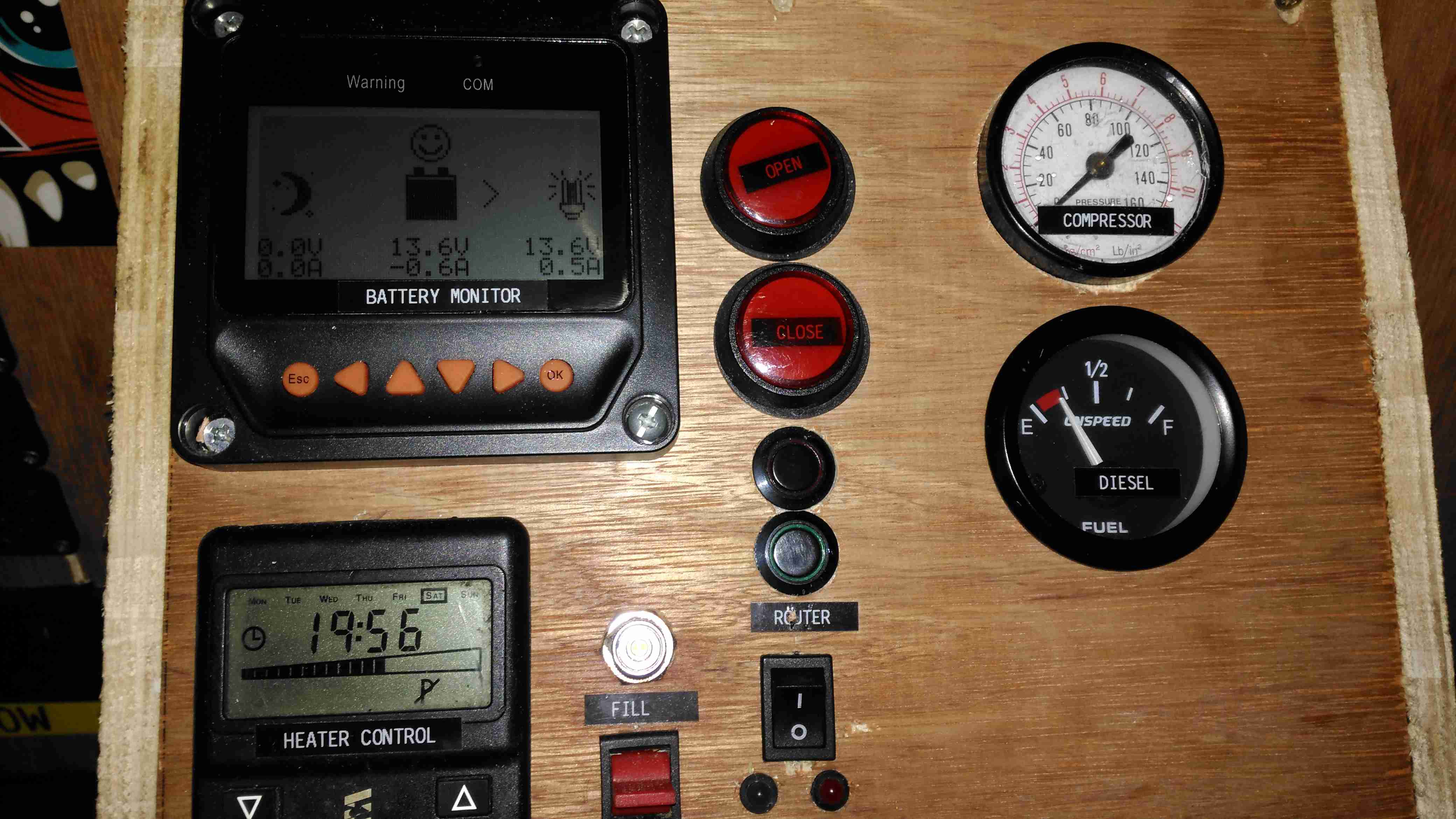
All the instruments & controls are on a single panel, with the Eberspacher thermostat, external fuelling port & pump switch, inverter control, the solar controller monitor panel, cover buttons, router controls, compressed air & fuel gauges.
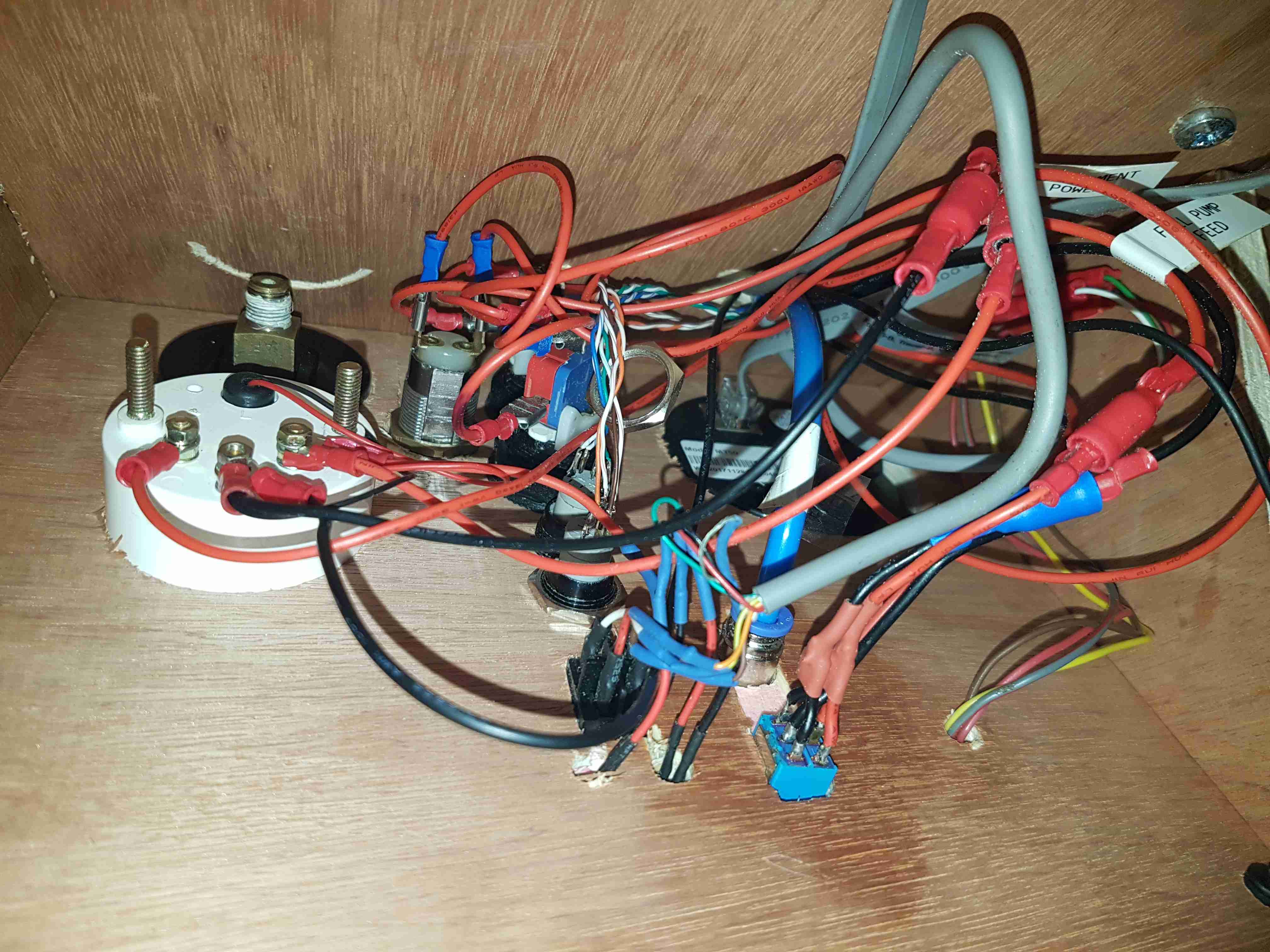
Panel Wiring
As is usual behind instrument panels, there’s a rat’s nest of wiring. There’s still the pressure gauge to connect up for the compressed air system, and the nut on one of the router buttons is such a tight fit I’ve not managed to get it into place yet.
Eberspacher Fuel Pump
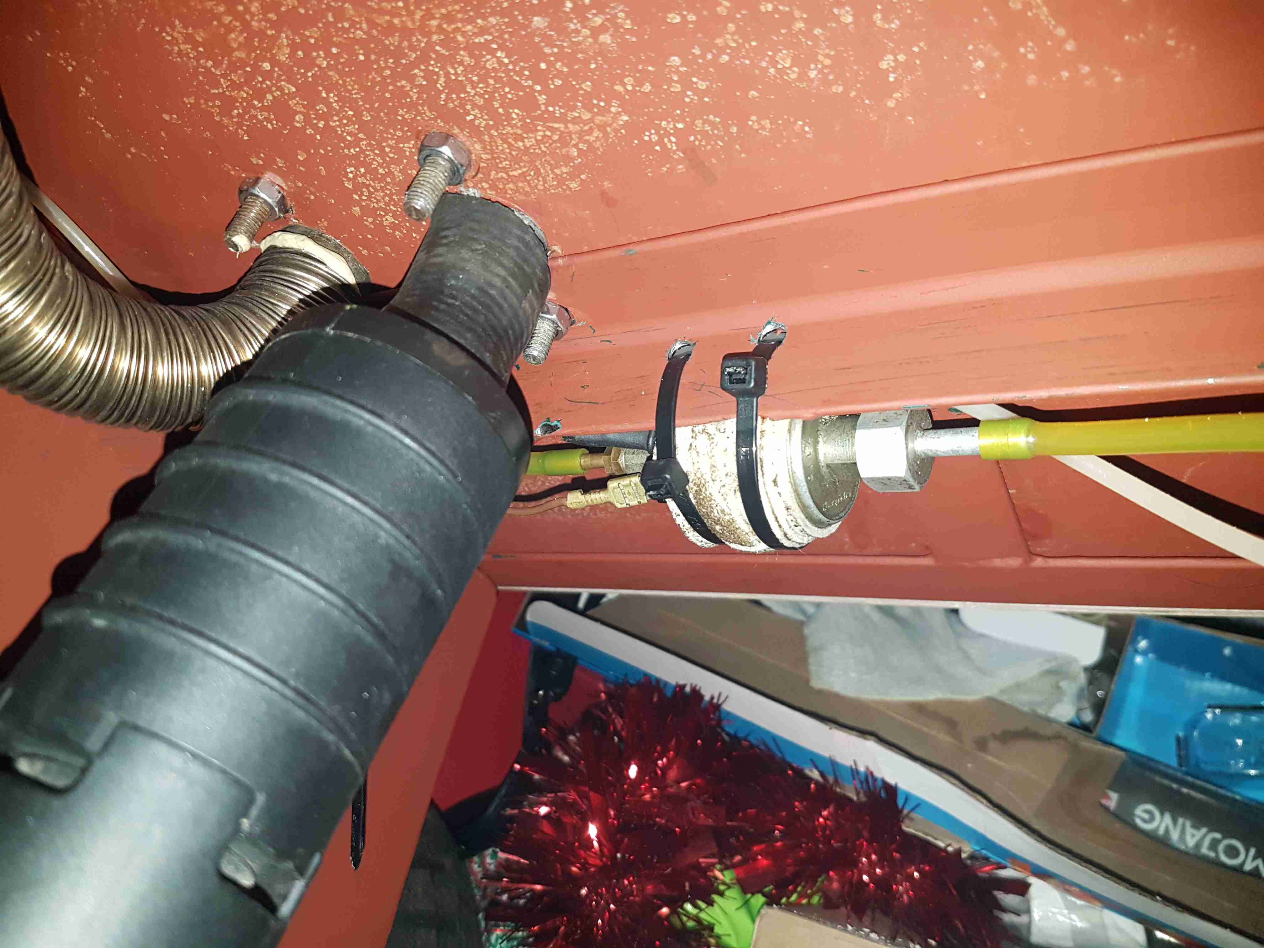
The support components for the Eberspacher heater are mounted underneath the baseplate, with the fuel dosing pump secured to a rail with a pair of cable ties, and some foam tape around to isolate the constant clicking noise these pumps create in operation. The large black cylinder is the combustion air intake silencer, with the stainless steel exhaust pipe to the left of that. Silencing these heaters is essential – they sound like a jet engine without anything to deaden the noise. Most of this is generated from the side-channel blower used in the burner.
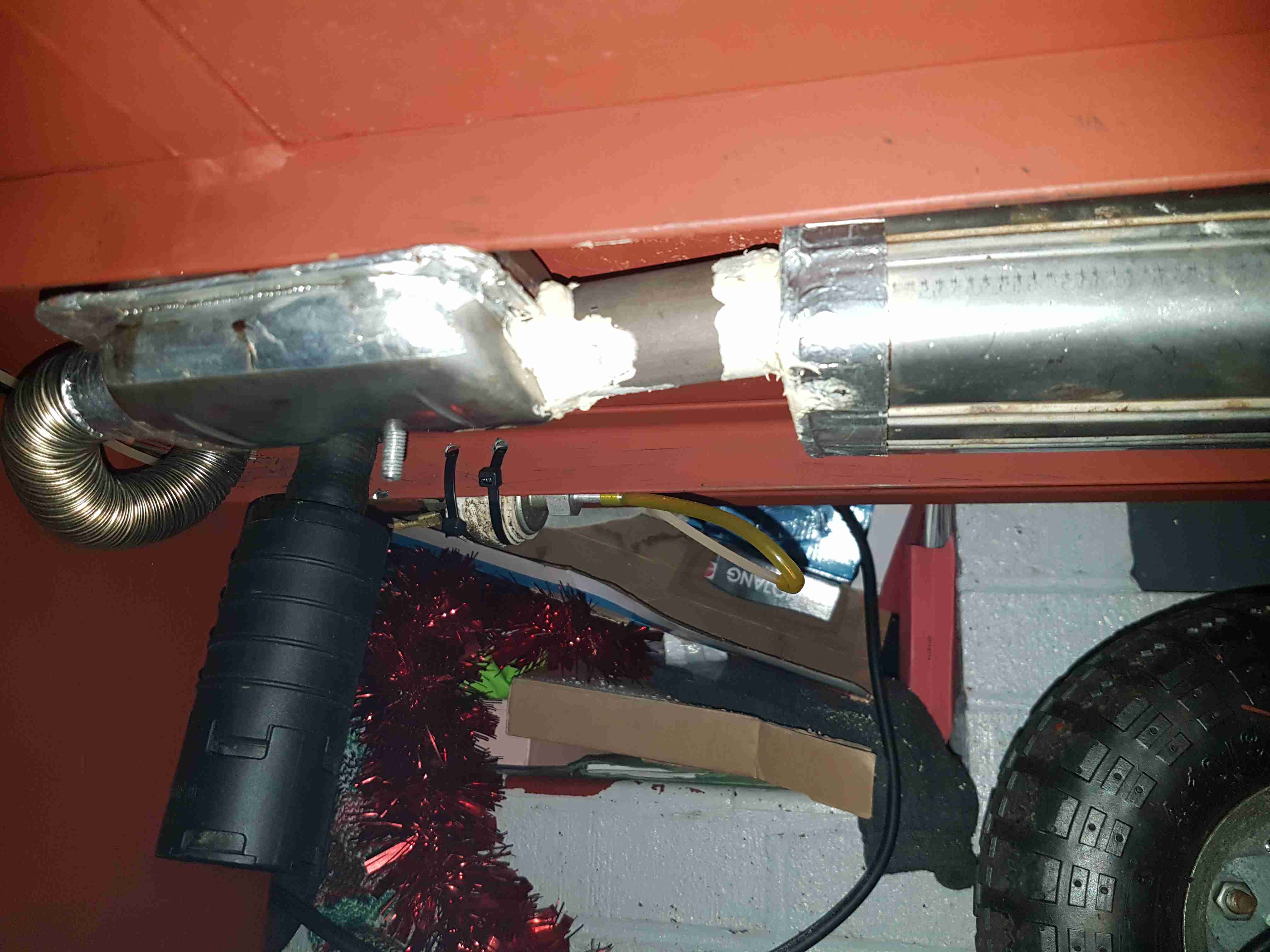
Eberspacher Exhaust
Bolted to the underside are a pair of exhaust silencers, one is an Eberspacher brand, the other is Webasto, since the latter type are better at reducing the exhaust noise. Connections are sealed with commerical exhaust assembly paste, the usual clamps supplied do not do a good enough job of stopping exhaust leaks.
Next update to come when I get the parts in for the air compressor system.
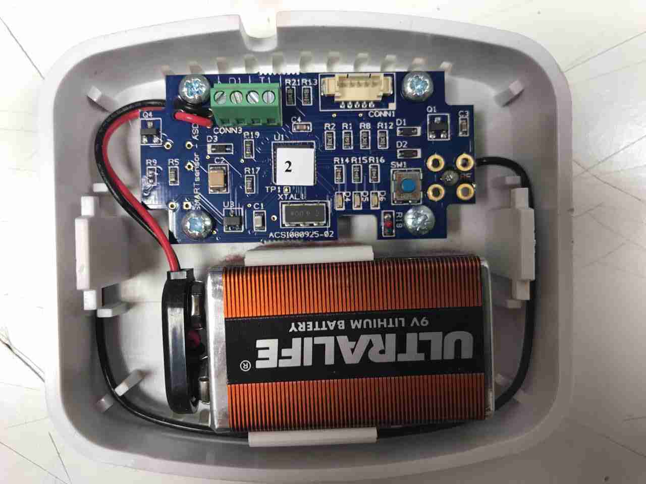
Here’s another random bit of RF tech, I’m told this is a wireless energy management sensor, however I wasn’t able to find anything similar on the interwebs. It’s powered by a standard 9v PP3 battery.
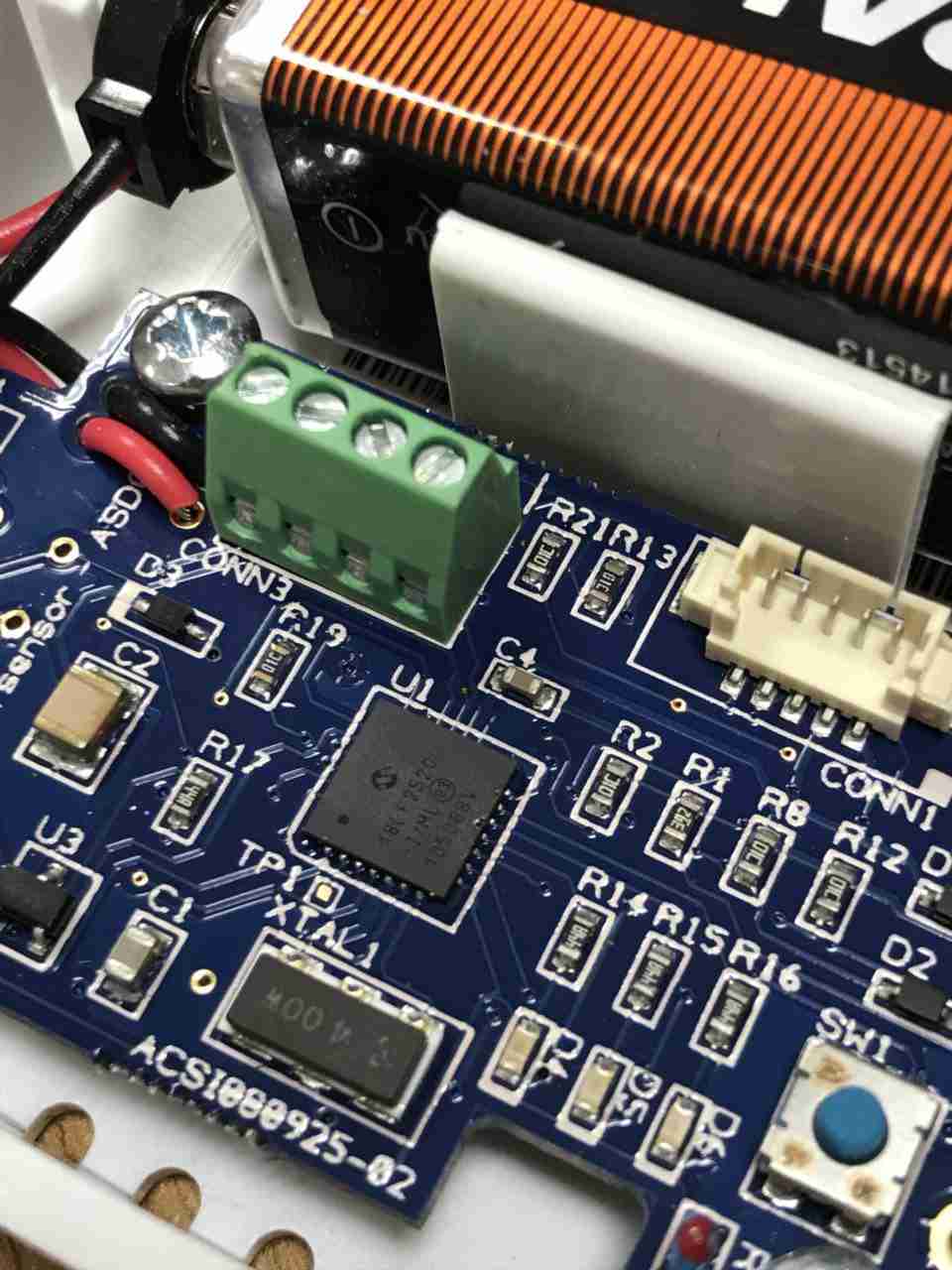
Microcontroller
System control is handled by this Microchip PIC18F2520 Enhanced Flash microcontroller, this has an onboard 10-bit ADC & nanoWatt technology according to their datasheet. There’s a 4MHz crystal providing the clock, with a small SOT-23 voltage regulator in the bottom corner. There’s a screw terminal header & a plug header, but I’ve no idea what these would be used for. Maybe connecting an external voltage/current sensor & a programming header? The tactile button I imagine is for pairing the unit with it’s controller.
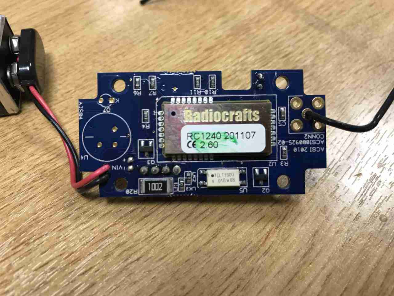
PCB Bottom
The bottom of the PCB is almost entirely taken up by a Radiocrafts RC1240 433MHz RF transceiver. Underneath there’s a large 10kΩ resistor, maybe a current transformer load resistor, and a TCLT1600 optocoupler. Just from the opto it’s clear this unit is intended to interface in some way to the mains grid. The antenna is connected at top right, in a footprint for a SMA connector, but this isn’t fitted.
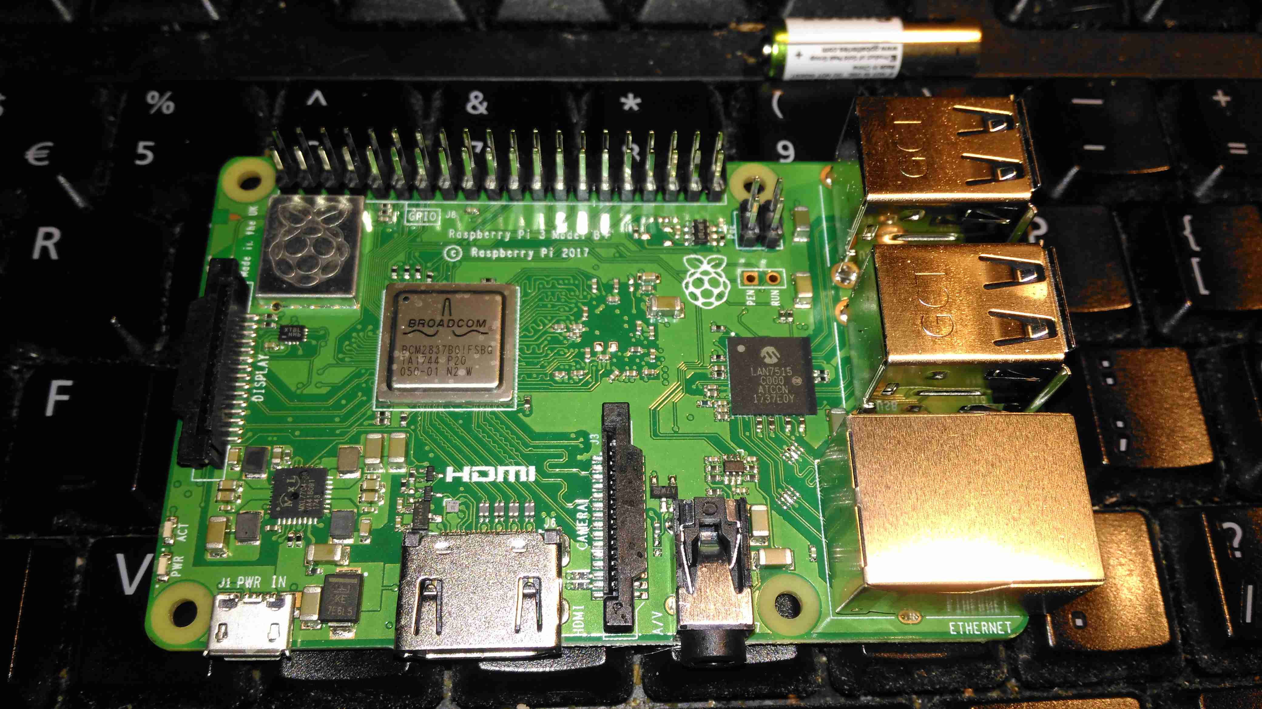
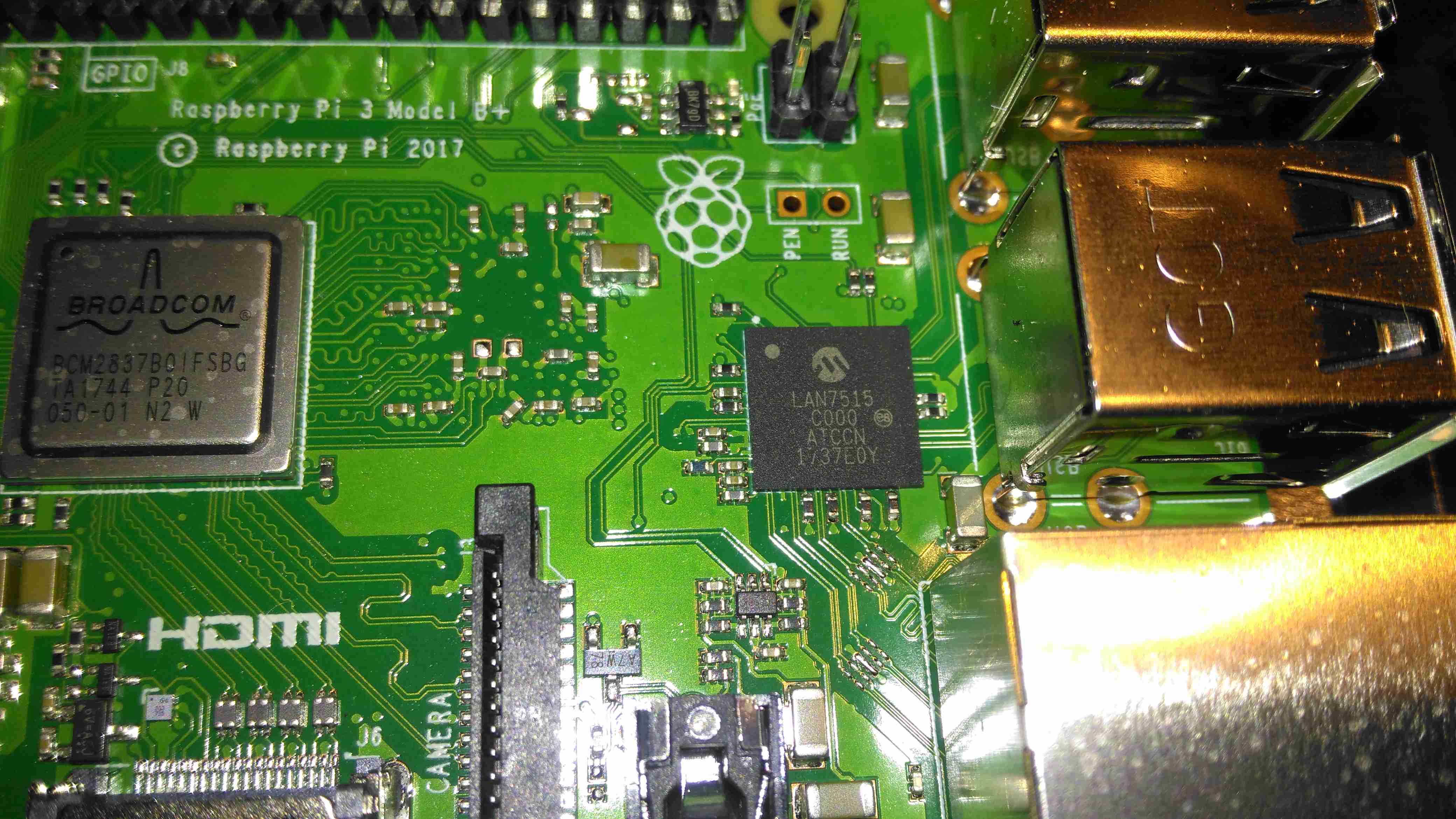
Yesterday, the Raspberry Pi community got a nice surprise – a new Pi! This one has some improved features over the previous RPi 3 Model B:
Improved CPU – 64-Bit 1.4GHz Quad-Core BCM2837B0
Improved WiFi – Dual Band 802.11b/g/n/ac. This is now under a shield on the top of the board.
Improved Ethernet – The USB/Ethernet IC has been replaced with a LAN7515, supporting gigabit ethernet. The backhaul is still over USB2 though, so this would max out at about 300Mbit/s
PoE Support – There’s a new 4-pin header, and a matching HAT for power over ethernet support.
Chipset
The USB/LAN Controller is now a BGA package, supporting gigabit ethernet. The USB connections are still USB2 though, limiting total bandwidth. This shouldn’t be much of an issue though, since anything over the 100Mbit connection we’ve had previously is an improvement.
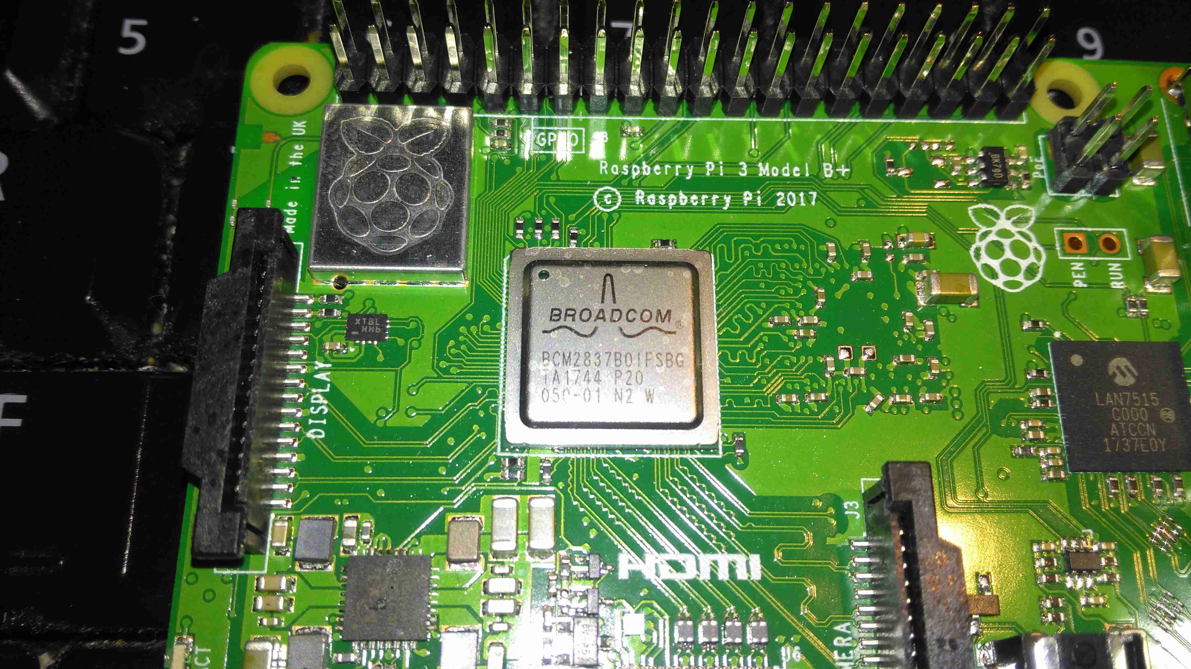
CPU & Radio
The CPU now has a metal heatspreader on top of the die, no doubt to help with cooling under heavy loads. As far as I know, it’s still the same silicon under the hood though. The WiFi radio is under the shielding can to the top left, with the PCB trace antenna down the left edge of the board.
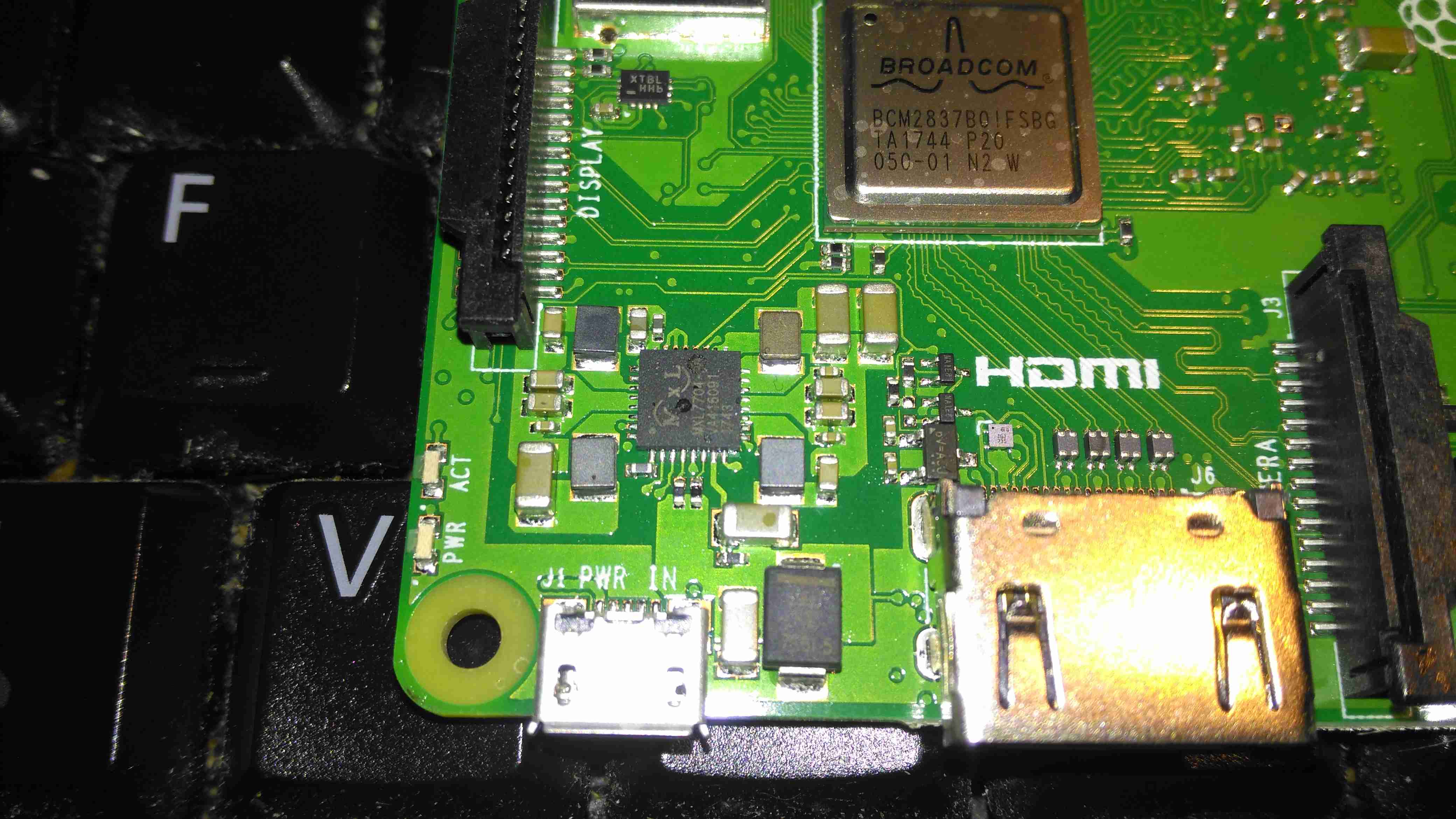
Power Controller
The power supplies are handled on this new Pi by the MaxLinear MxL7704, from what I can tell from MaxLinear’s page, it seems to be somewhat of a collaborative effort to find something that would do the best job, since they apparently worked with the Foundation to get this one right. This IC apparently includes four synchronous step-down buck regulators that provide system, memory, I/O and core power from 1.5A to 4A. An on-board 100mA LDO provides clean 1.5V to 3.6V power for analog sub-systems. This PMIC utilizes a conditional sequencing state machine that is flexible enough to meet the requirements of virtually any processor.
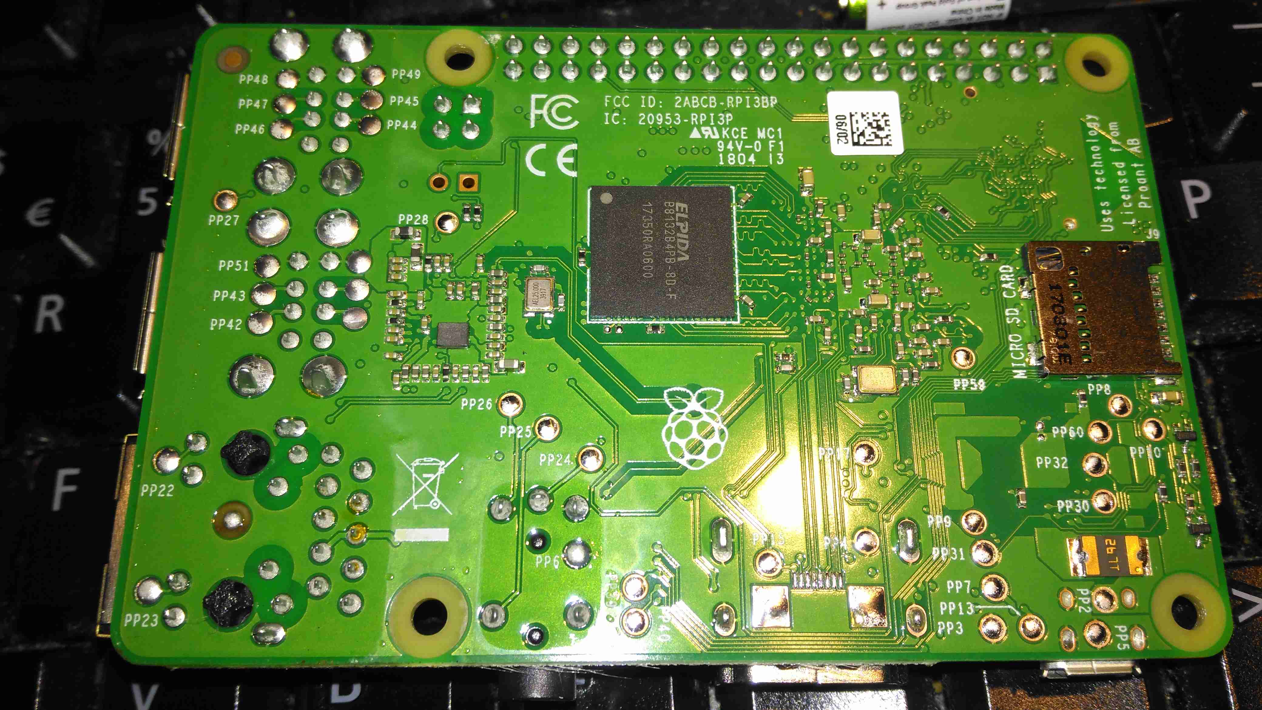
PCB Bottom
The bottom of the PCB has the Elpida 1GB RAM package, which is LPDDR2, along with the MicroSD slot.
A quick benchmark running Raspbian Lite & a SanDisk Ultra 32GB Class 10 SD card gives some nice results:
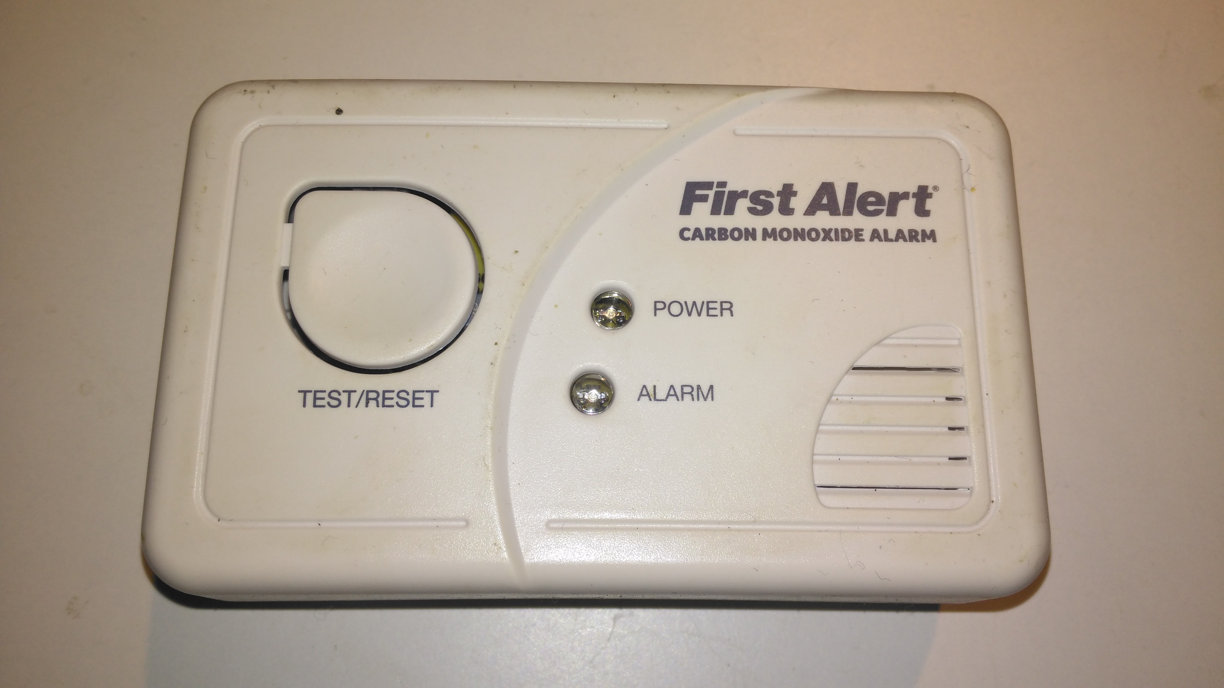
Here’s another domestic CO Alarm, this one a cheaper build than the FireAngel ones usually use, these don’t have a display with the current CO PPM reading, just a couple of LEDs for status & Alarm.
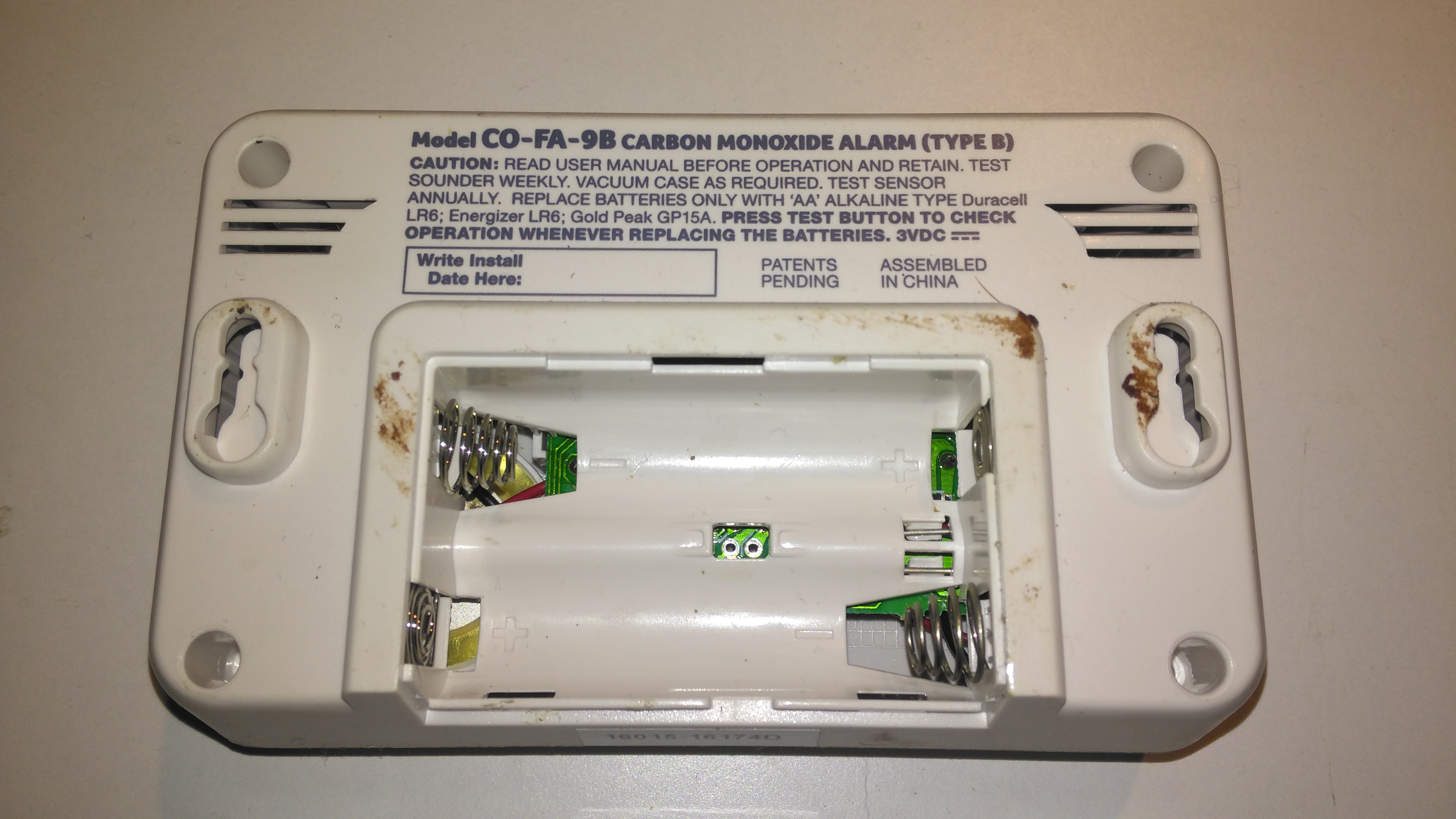
Rear
This alarm also doesn’t have the 10-year lithium cell for power, taking AA cells instead. The alarm does have the usual low battery alert bleeps common with smoke alarms though, so you’ll get a fair reminder to replace them.
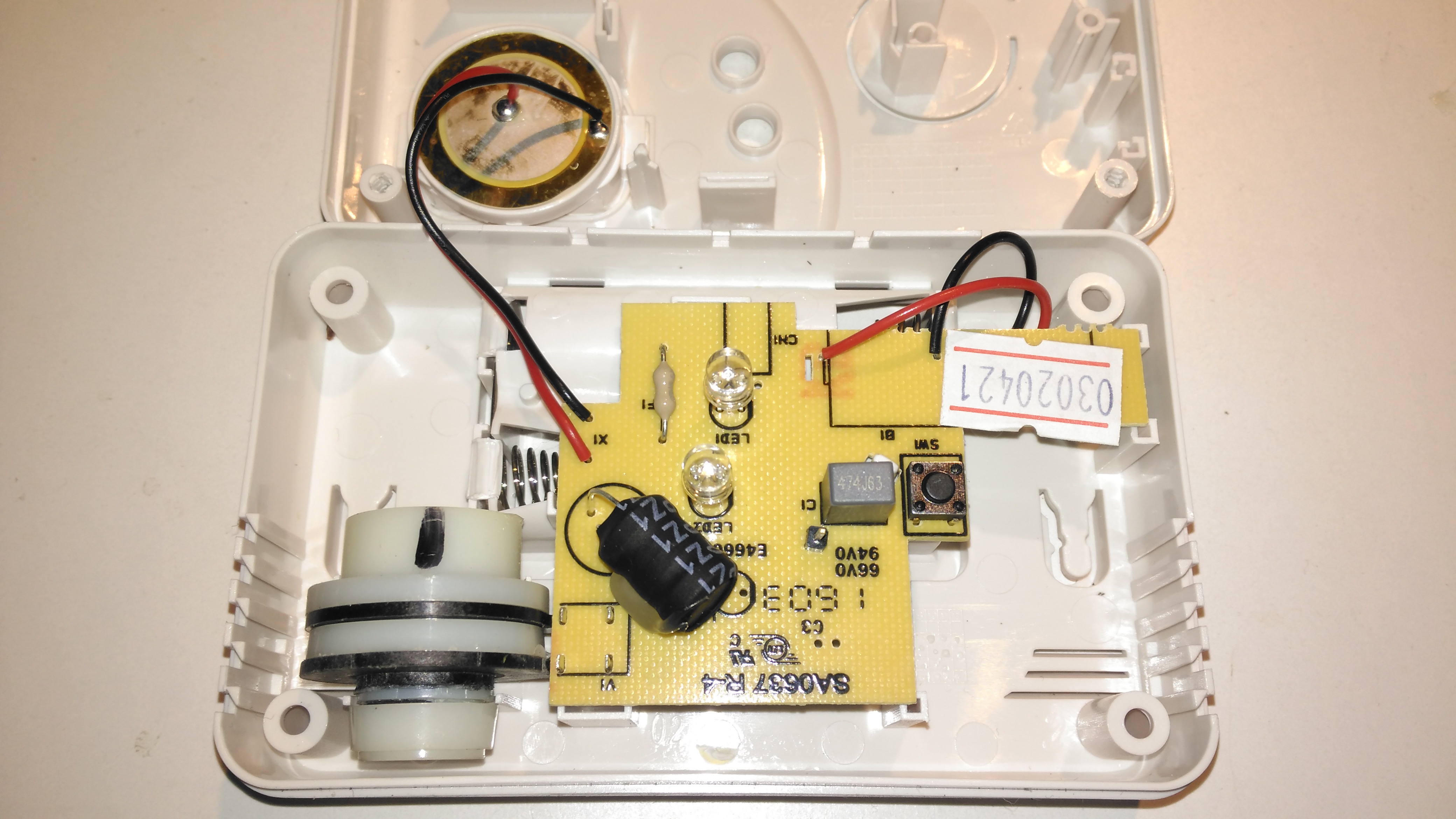
Internals
Not much at all on the inside. The CO sensor cell is the same one as used in the FireAngel alarms, I have never managed to find who manufactures these sensors, or a datasheet for them unfortunately.
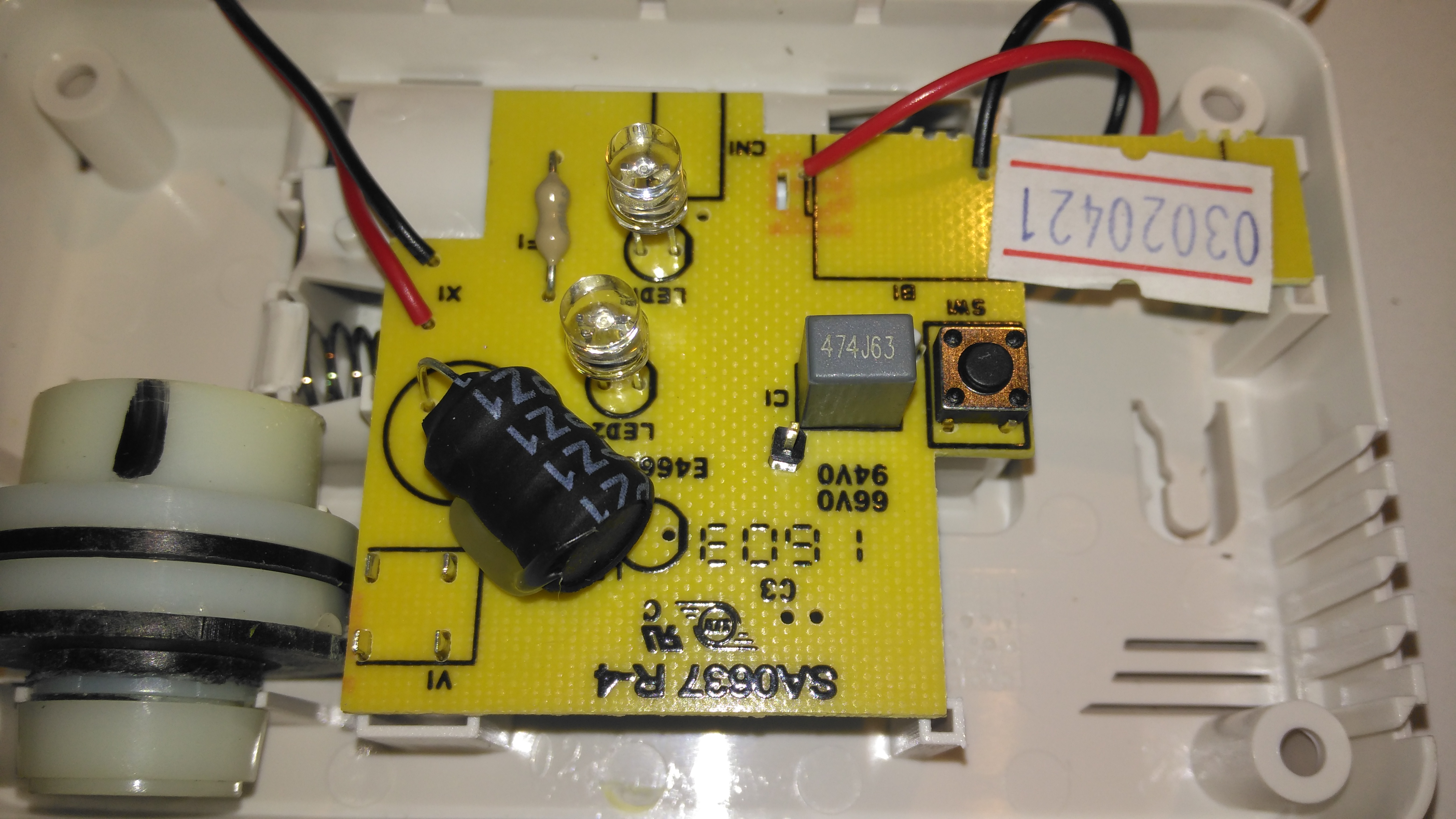
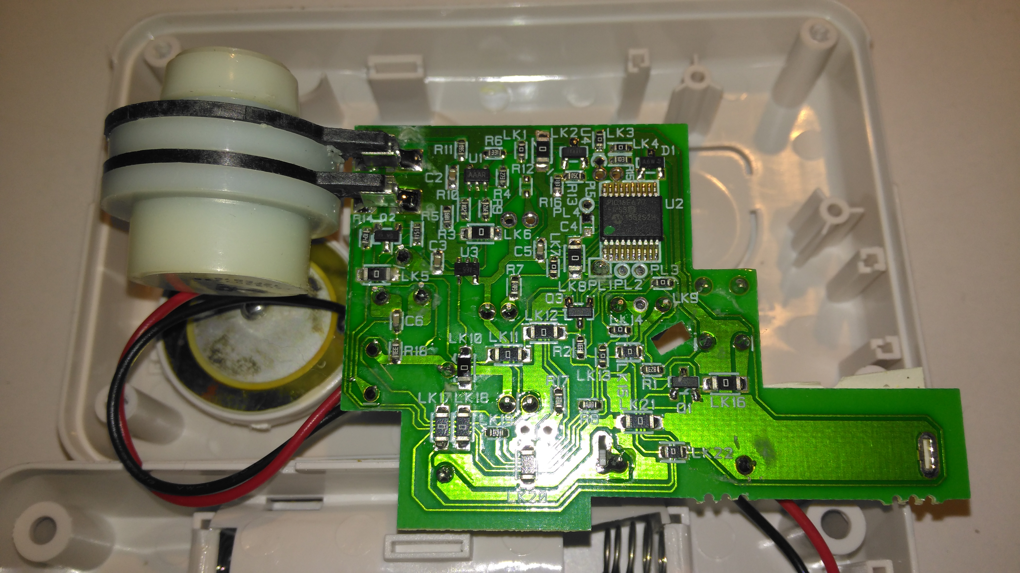
PCB Top
The top of the single sided PCB has the transformer for driving the Piezo sounder, the LEDs & the test button.
PCB Bottom
All the magic happens on the bottom of the PCB. The controlling microcontroller is on the top right, with the sensor front end on the top left.
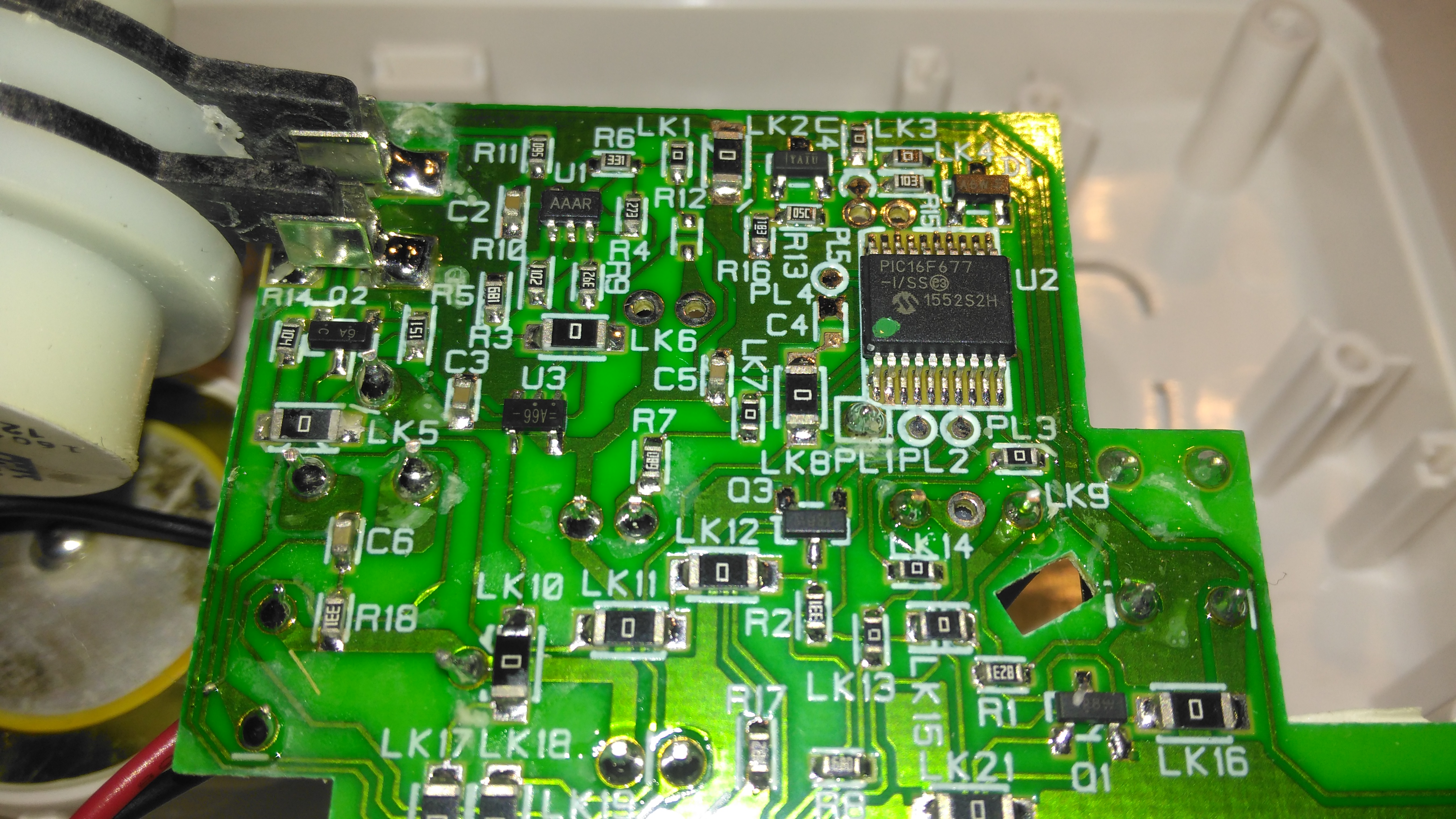
Circuitry Closeup
The microcontroller used here is a Microchip PIC16F677. I’ve not managed to find datasheets for the front end components, but these will just be a low-noise op-amp & it’s ancillaries. There will also be a reference voltage regulator. The terminals on these sensors are made of conductive plastic, probably loaded with carbon.
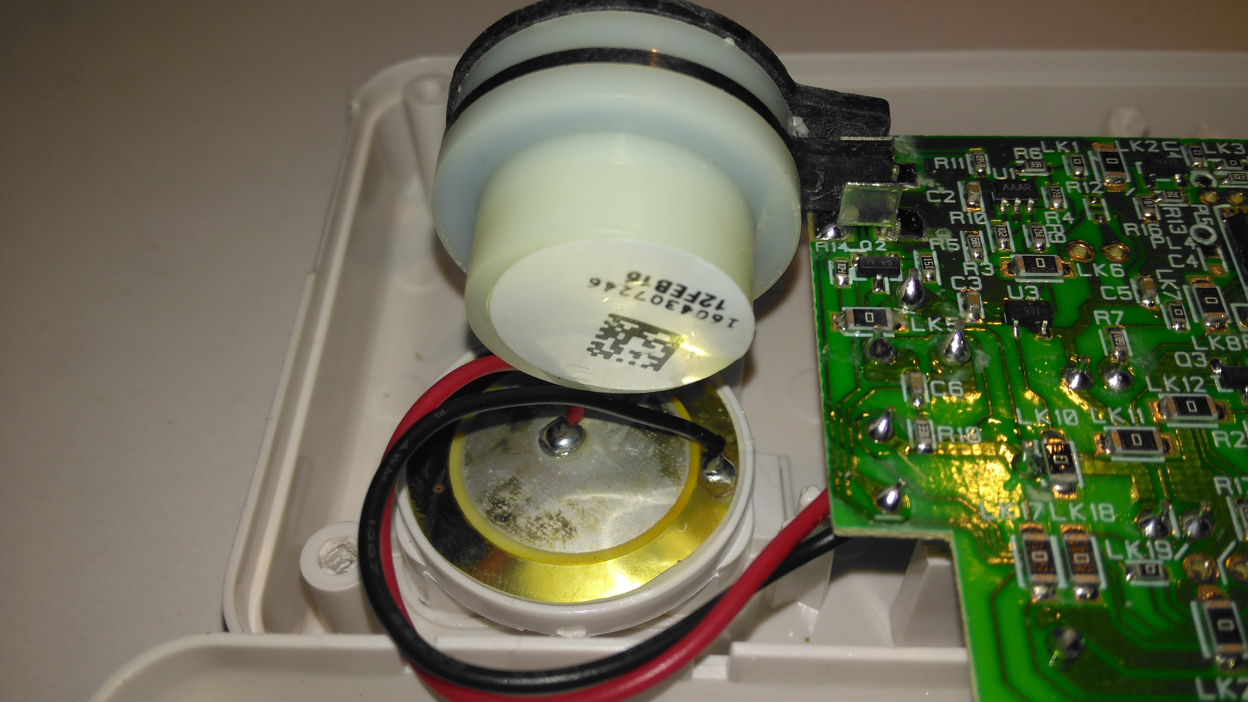
Sensor Cell & Piezo Disc
The expiry date is handily on a label on the back of the sensor, the Piezo sounder is just underneath in it’s sound chamber.
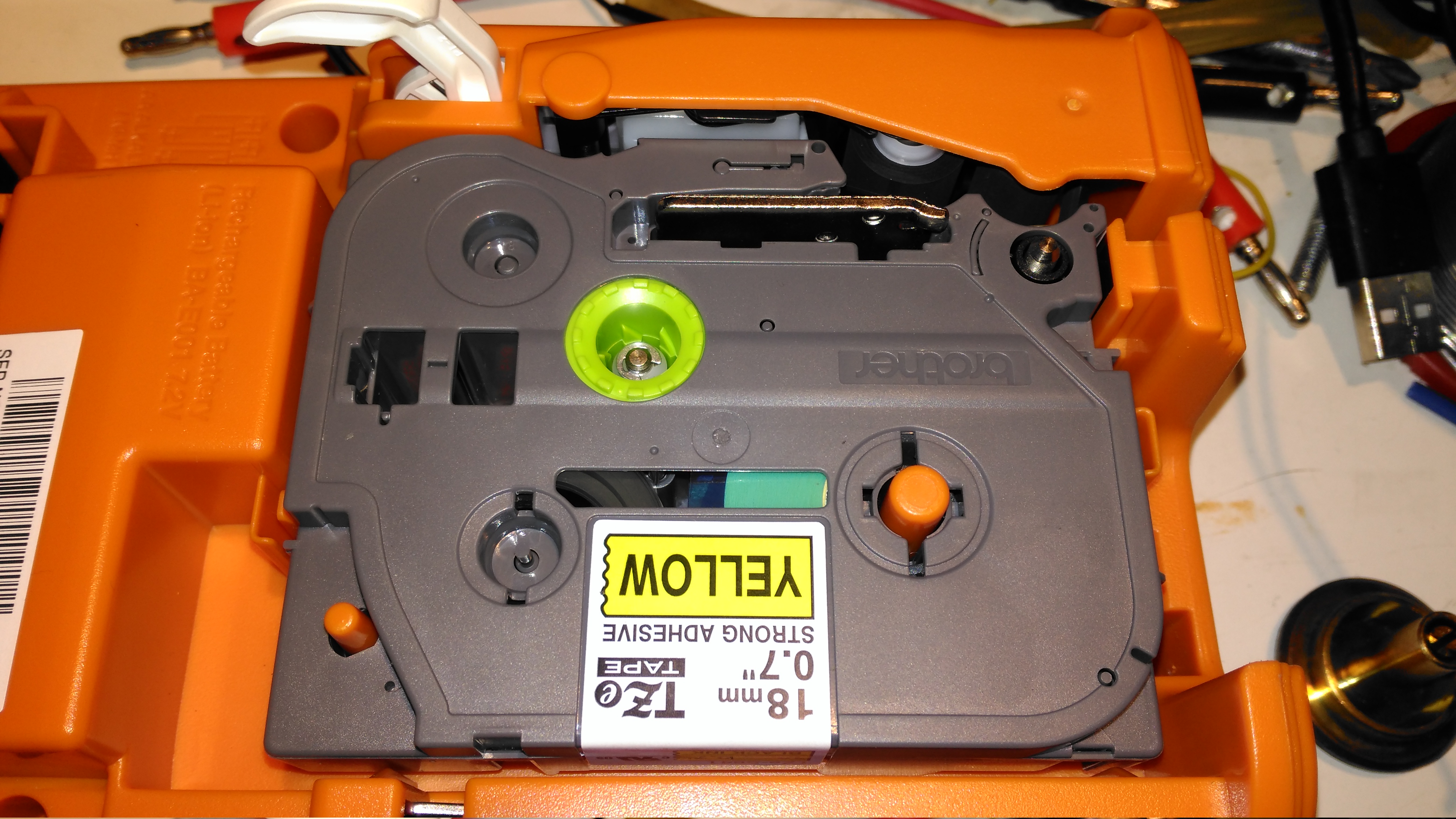
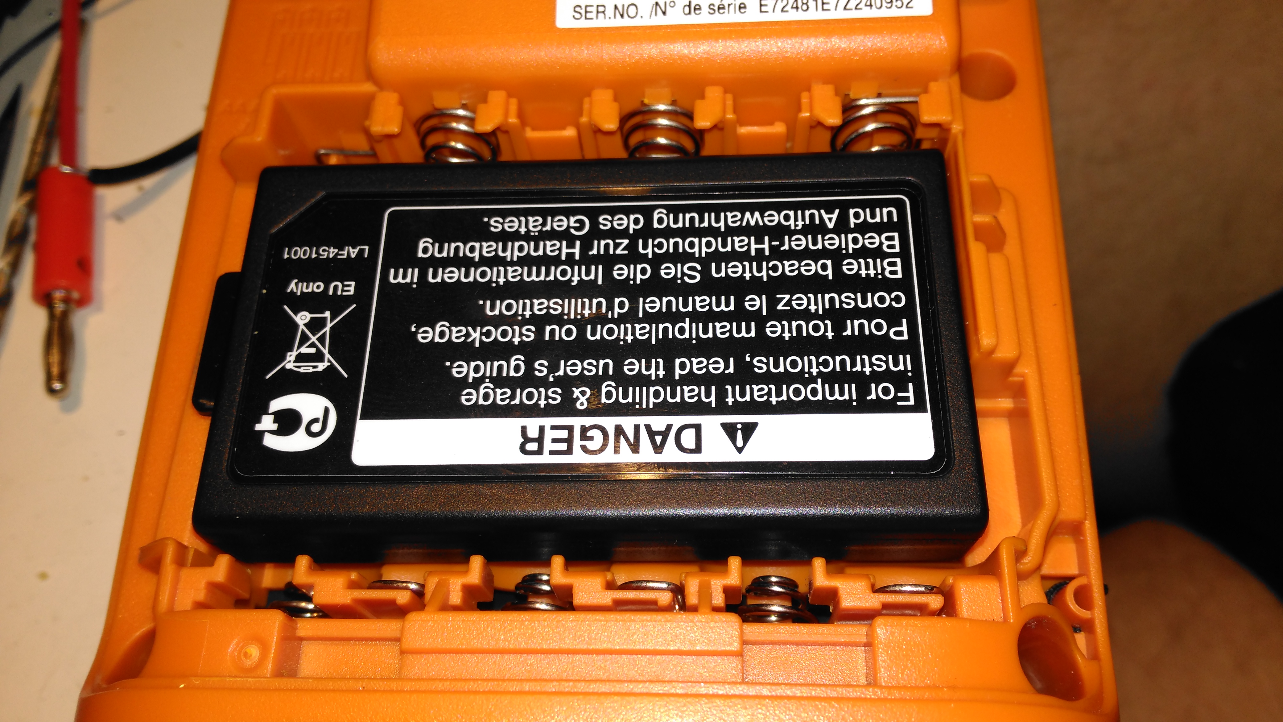
Here a tape is installed in the printer. This unit can handle tape widths up to 18mm. The pinch rollers are operated by the white lever at the top of the image, which engages with the back cover.
Li-Ion Battery
This printer is supplied with a rechargeable battery pack, but AA cells can be used as well. Some of the AA battery terminals can be seen above the battery.
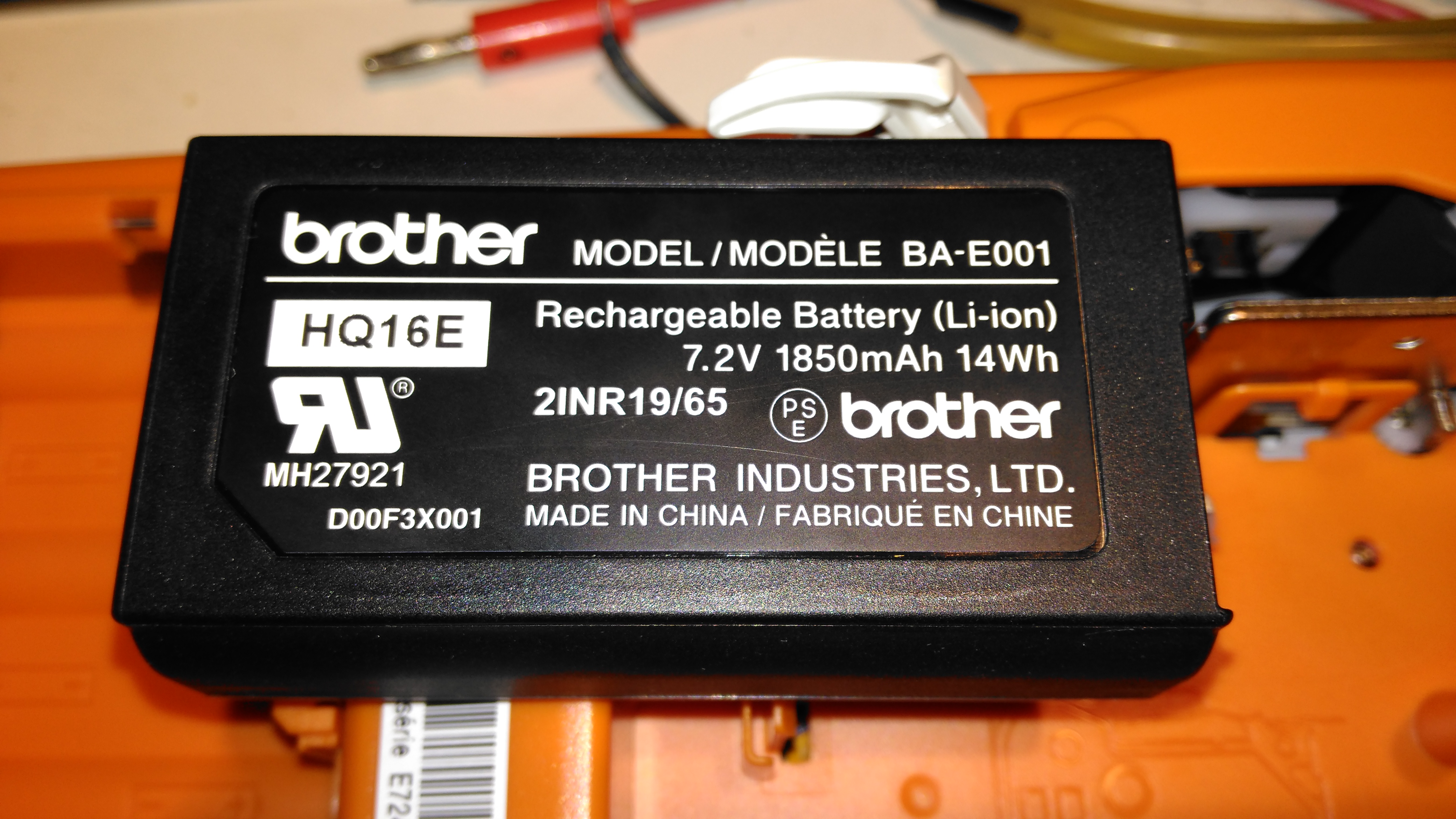
Battery Specs
Pretty standard fare for a 2-cell lithium pack. The charging circuitry doesn’t appear to charge it to full voltage though, most likely to get the most life from the pack.
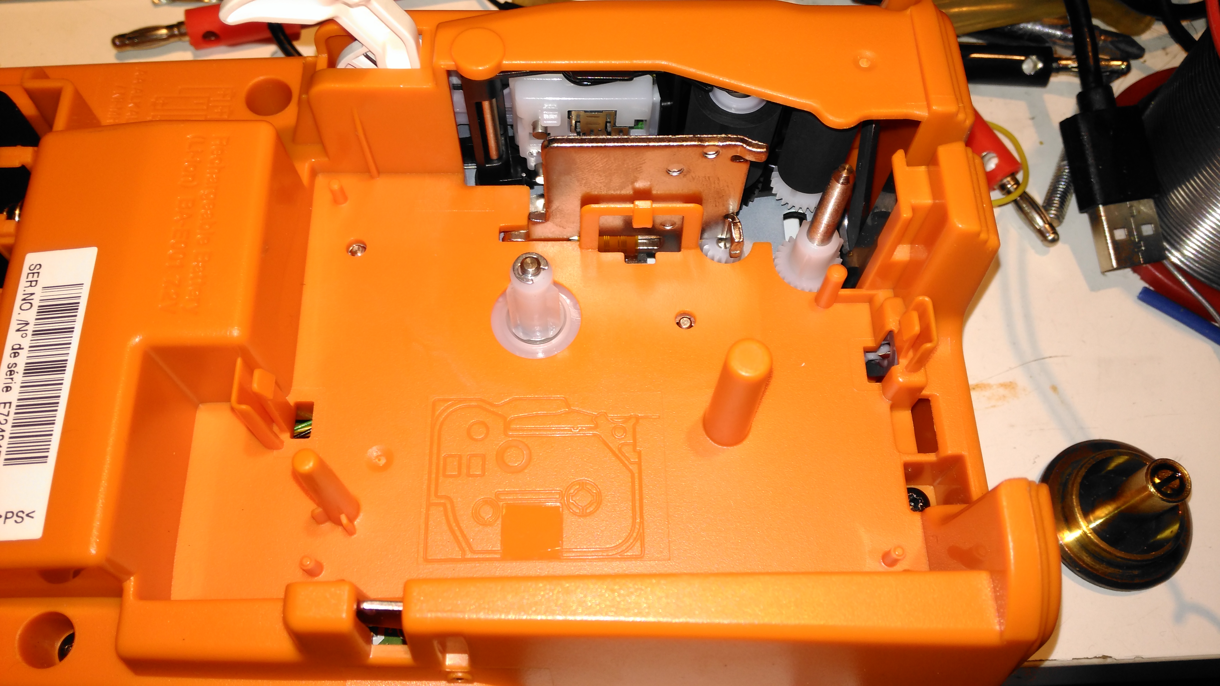
Cartridge Slot
With the cartridge removed, the printer components can be seen. As these cartridges have in effect two rolls, one fro the ribbon & one for the actual label, there are two drive points.
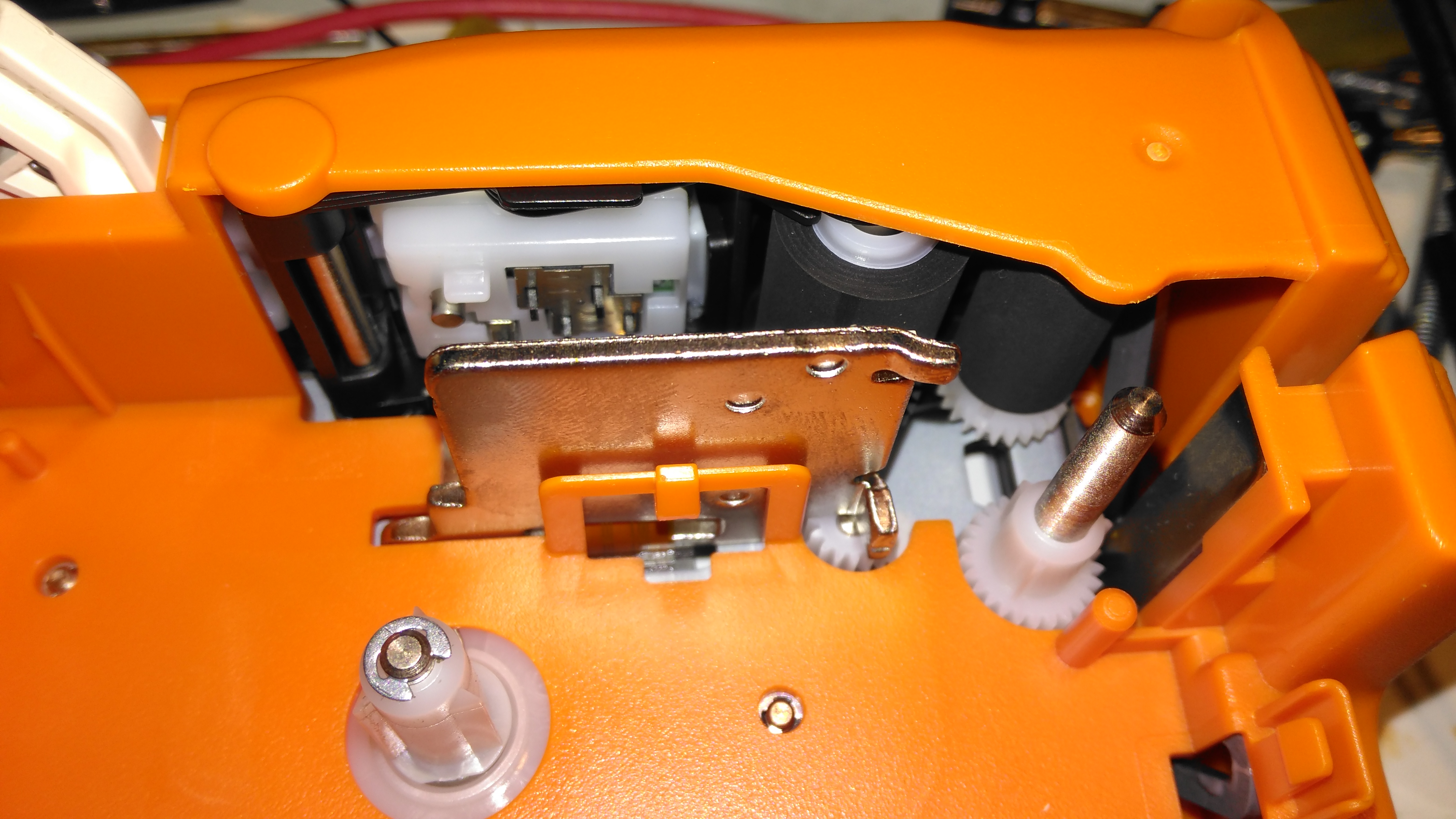
Pinch Rollers & Print Head
The thermal print head is hidden on the other side of the steel heatsink, while the pinch rollers are on the top right. The plastic piece above the print head heatsink has a matrix of switches that engage with holes in the top of the label cartridge, this is how the machine knows what size of ribbon is fitted.
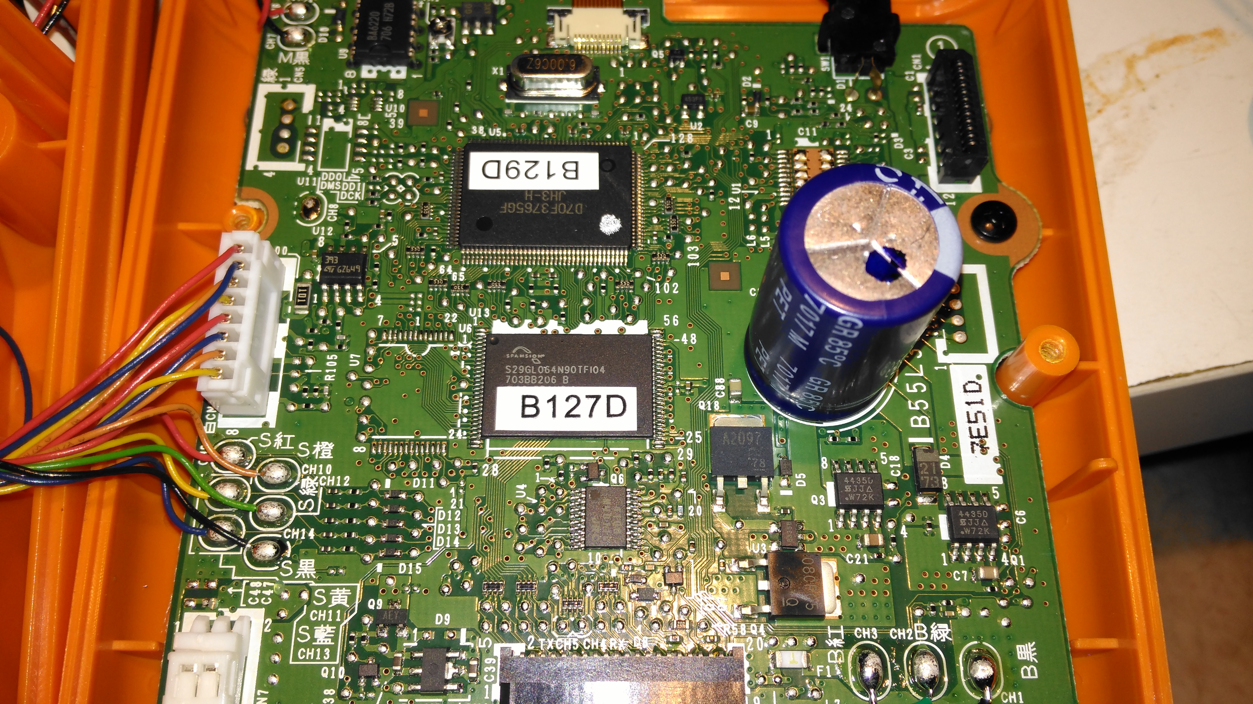
Mainboard
Most of the internal space is taken up by the main board, with the microprocessor & it’s program flash ROM top & centre.
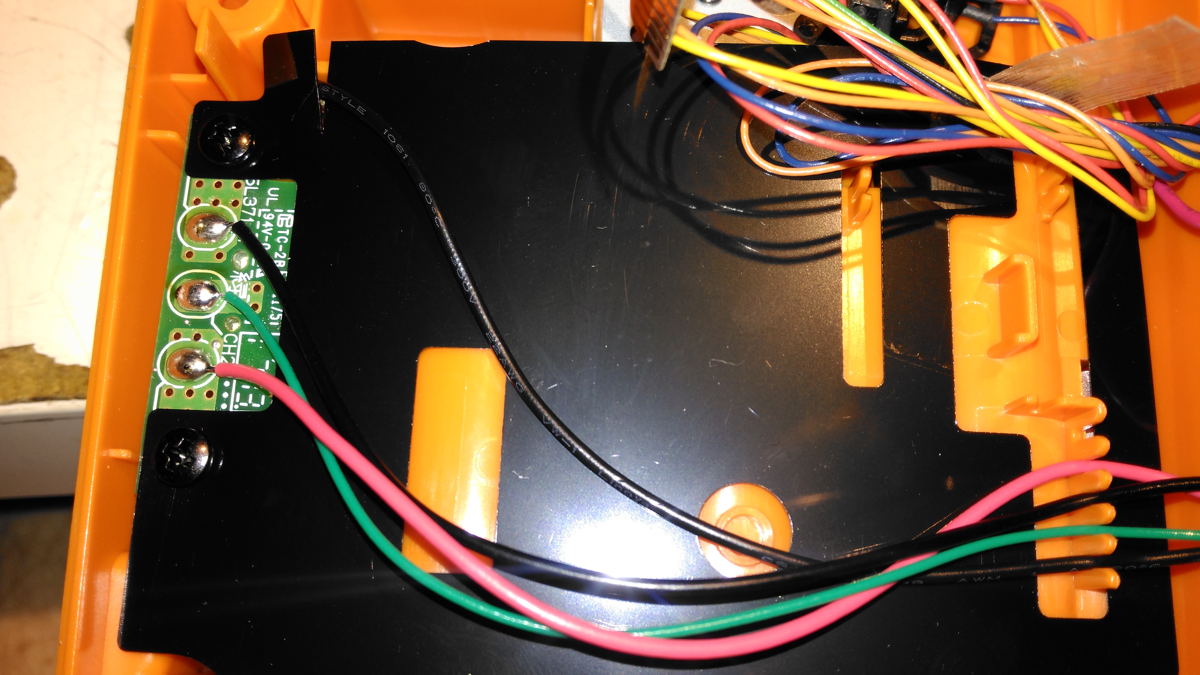
Charger Input
The charger input is located on the keyboard PCB just under the mainboard, which is centre negative, as opposed to 99% of other devices using centre positive, the bastards.
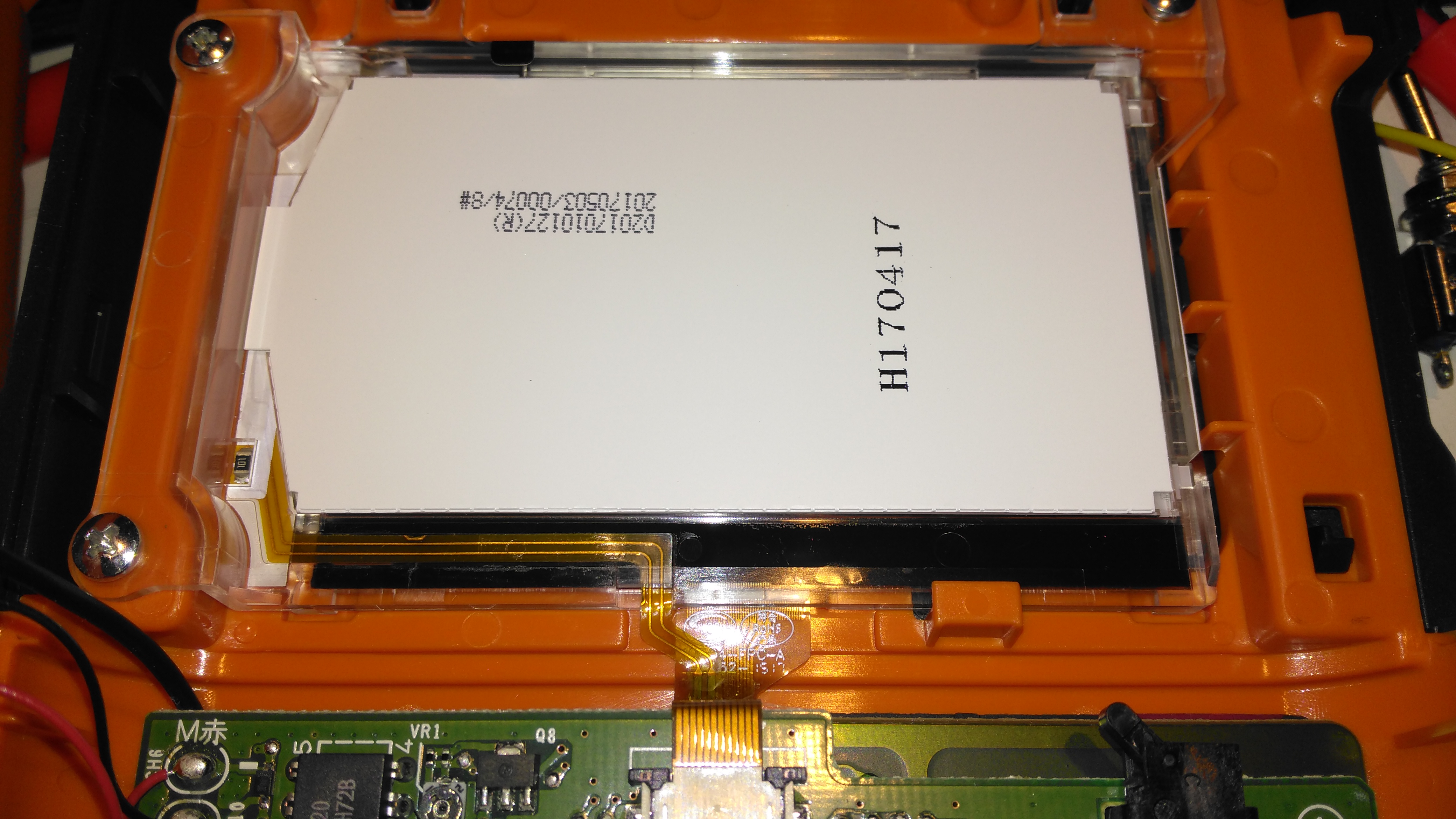
LCD Module
The dot-matrix LCD is attached to the mainboard with a short flex cable, and from the few connections, this is probably SPI or I²C.
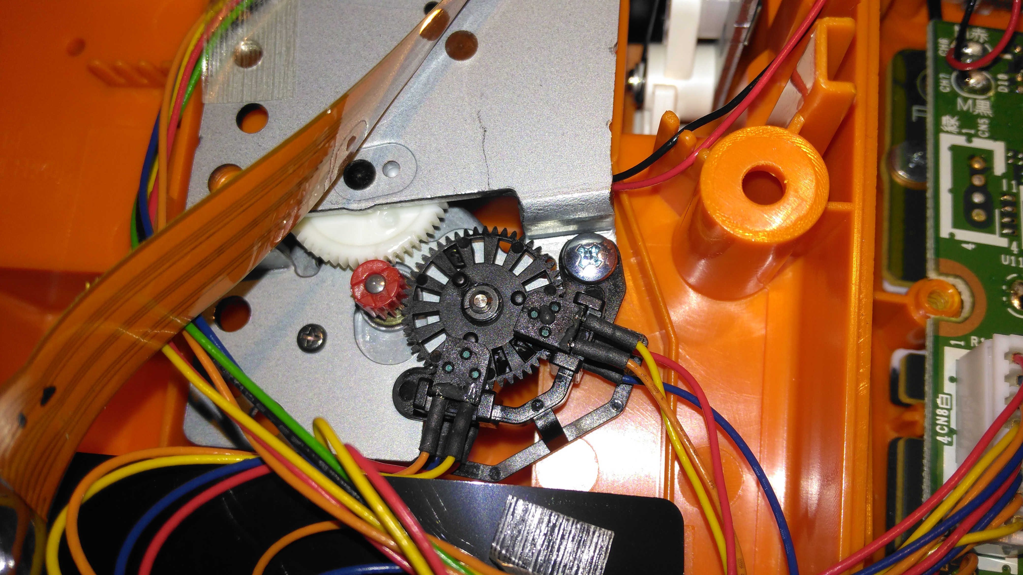
Print Mech Drive
The printer itself is driven by a simple DC motor, speed is regulated by a pair of photo-interrupters forming an encoder on the second gear in the train.
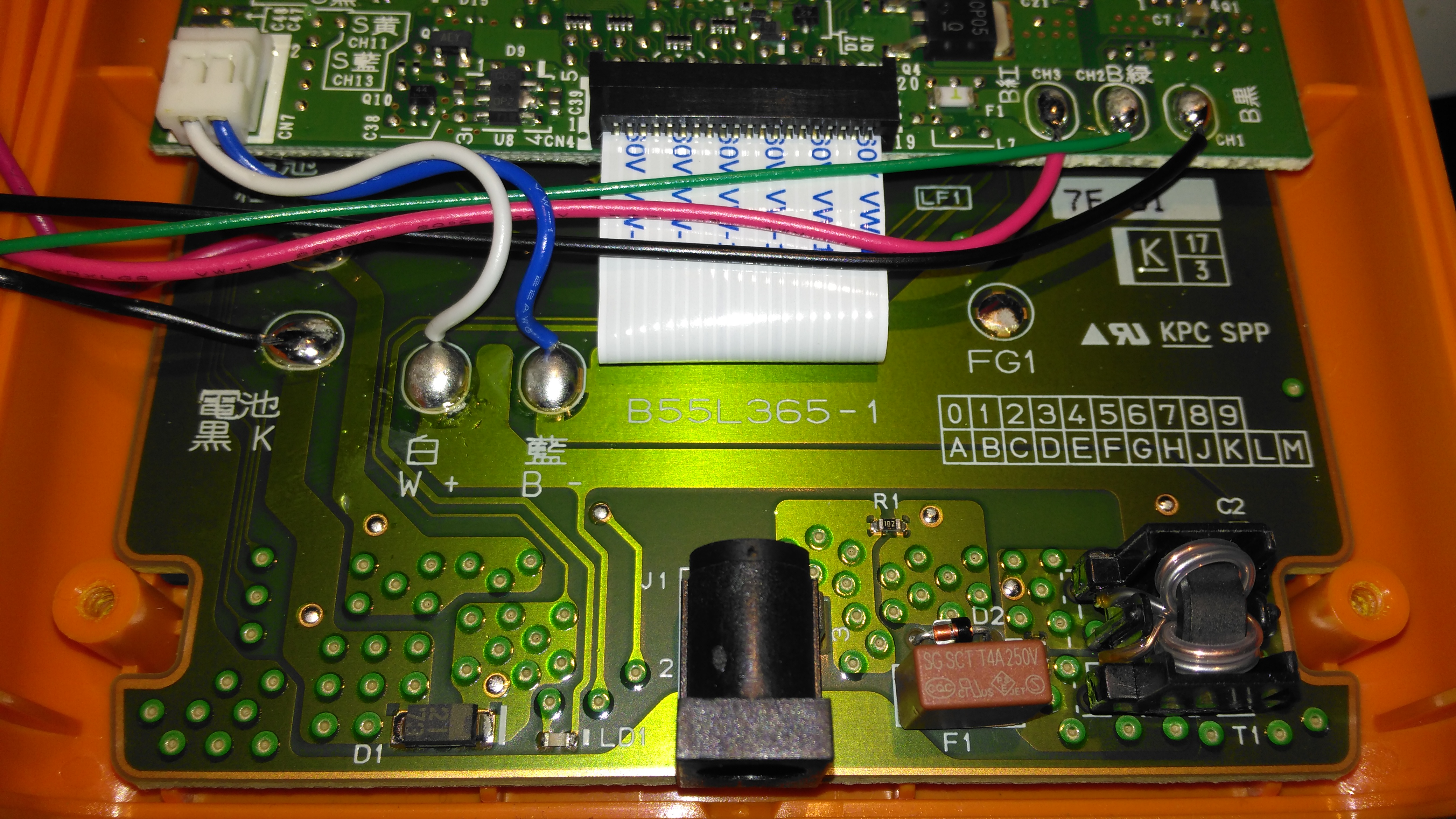
Battery Holder Connections
The back case has the battery connections for both the lithium pack & the AA cells, the lithium pack has a 3rd connection, probably for temperature sensing.
Since I do my own PCBs on a somewhat regular basis, I decided it was time to move to a more professional method to etch my boards. I have been using the cheap toner transfer method, using special yellow coated paper from China. (I think it’s coated in wax, or some plastic film).
The toner transfer paper does usually work quite well, but I’ve had many issues with pinholes in the transfer, which cause the etched tracks to look horrid, (not to mention the potential for breaks & reduced current capacity), and the toner not transferring properly at all, to issues with the paper permanently fusing to the copper instead of just transferring the toner.
BigClive has done a couple of fairly comprehensive videos on the dry film photoresist available from AliExpress & eBay. This stuff is used similarly to the toner transfer method, in that the film is fused to the board with heat, but then things diverge. It’s supplied either in cut sheets, or by the roll. I ordered a full roll to avoid the issues I’ve heard of when the stuff is folded in the post – once it’s creased, it’s totally useless. The dry film itself is a gel sandwiched between two protective plastic film sheets, and bonds to the board with the application of heat from a laminator.
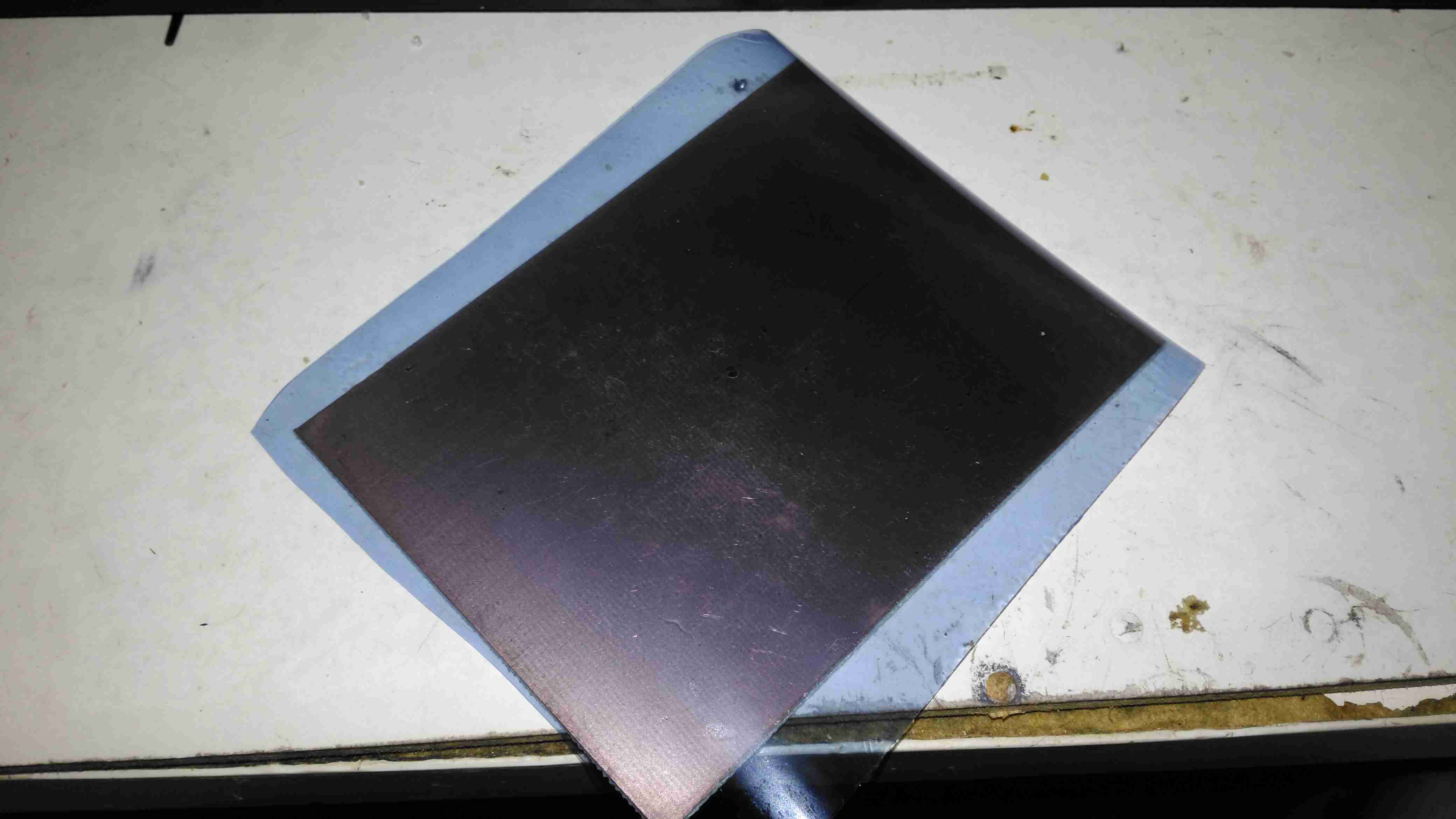
The board is first cleaned with scotchbrite pad & soap to remove any tarnish & oil from the copper.
Dry Film
Once the board has been cleaned, one side of the backing film is removed from the gel with adhesive tape, and the dry film is placed on the board while still wet. This stops the film from sticking immediately to the clean copper, one edge is pressed down, and it’s then fed through a modified laminator:
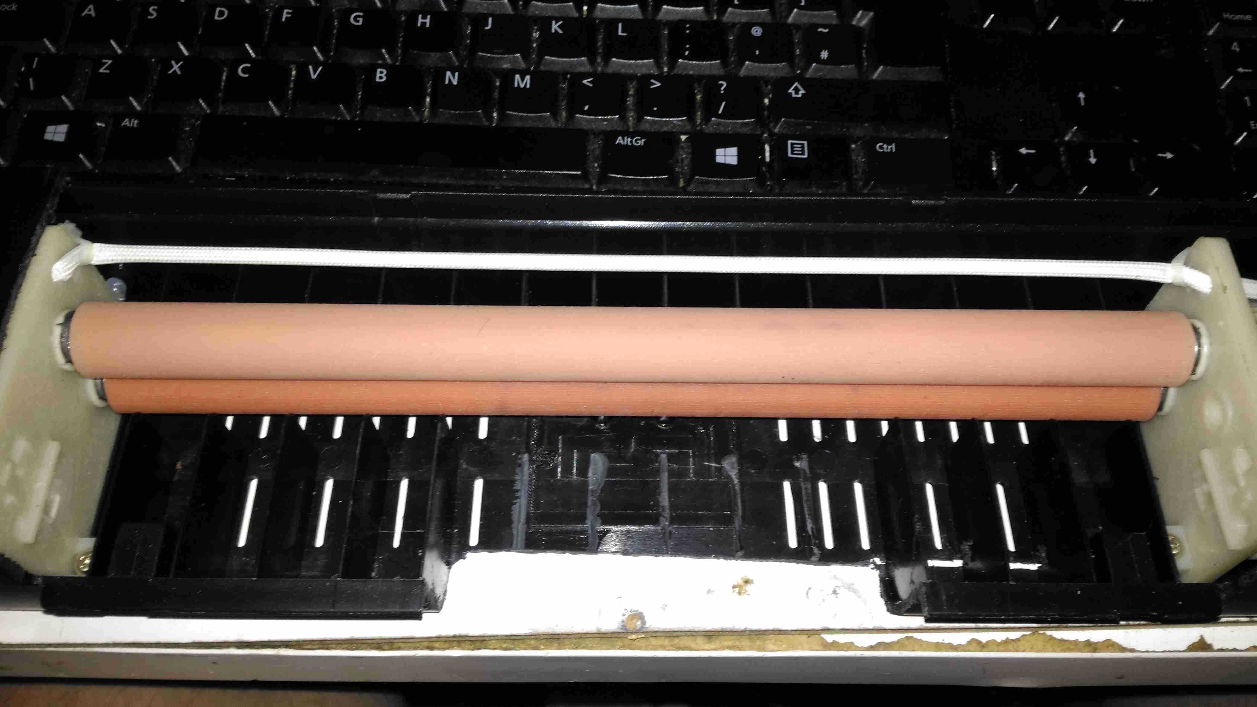
Modified Laminator
I’ve cut away most of the plastic covering the hot rollers, as constant jamming was an issue with this cheapo unit. All the mains power is safely tucked away under some remaining plastic cover at the end. The board with it’s covering of dry film is fed into the laminator – the edge that was pressed down first. This allows the laminator to squeeze out any remaining water & air bubbles from between the two so no creases or blisters form.
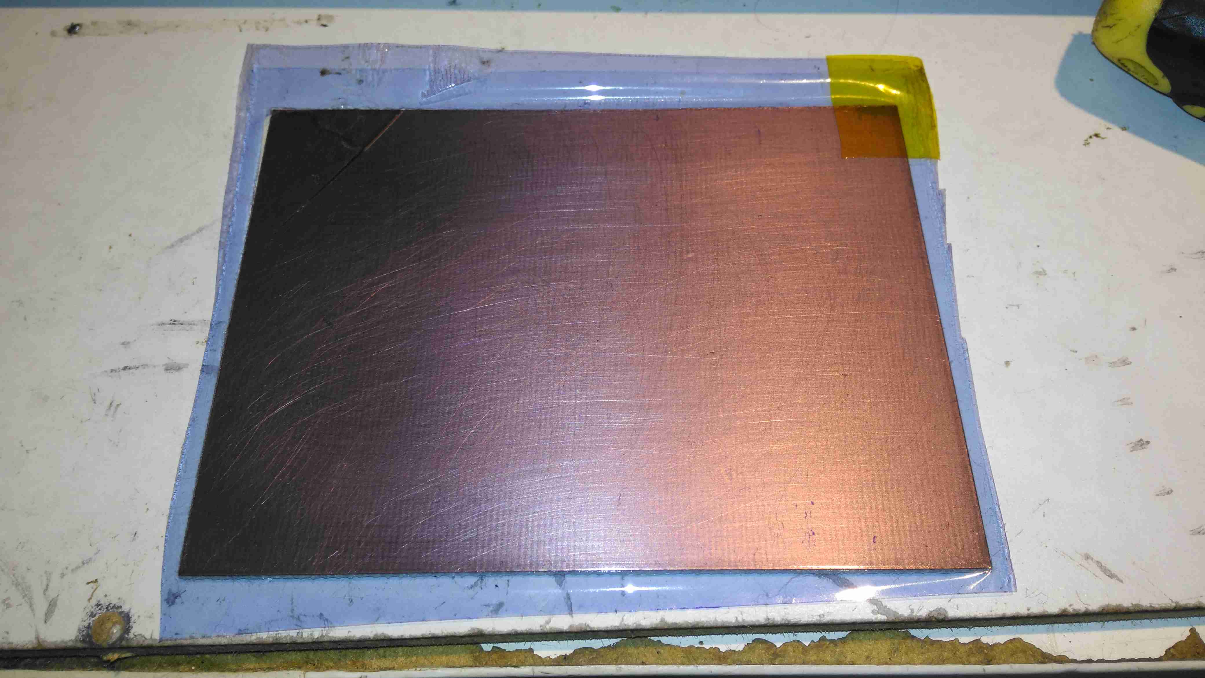
After Lamination
Once the board has been run through the laminator about 6 times, (enough to get it very hot to the touch), the film is totally bonded to the copper. The top film is left in place to protect the UV sensitive layer during expsure.
Photomask
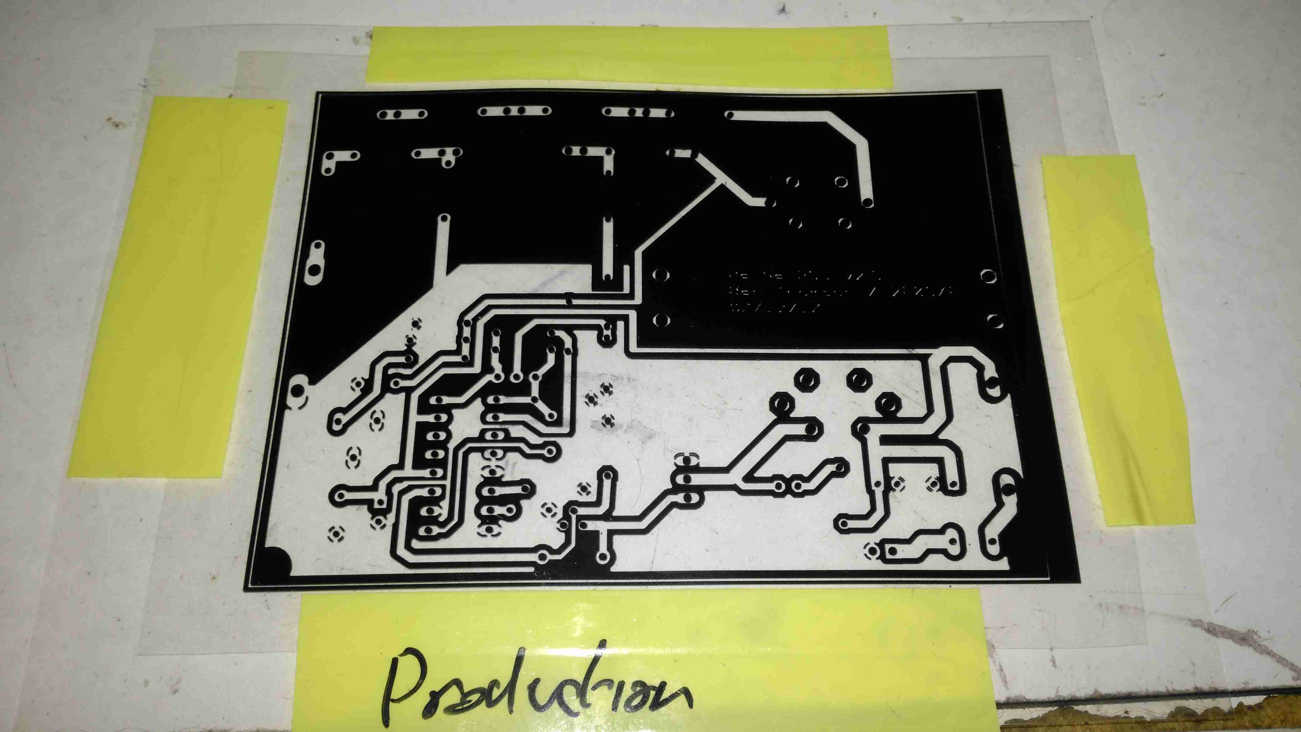
The exposure mask is laser printed onto OHP transparencies, in this case I’ve found I need to use two copies overlaid to get enough opacity in the black toner sections to block the UV light. Some touching up with a Sharpie is also easy to do if there are any weak spots in the toner coverage. This film is negative type – All the black areas will be unexposed and washed off in the developer tank. I also found I had to be fairly generous with track spacing, using too small lines just causes issues with the UV curing bits of film it isn’t supposed to.
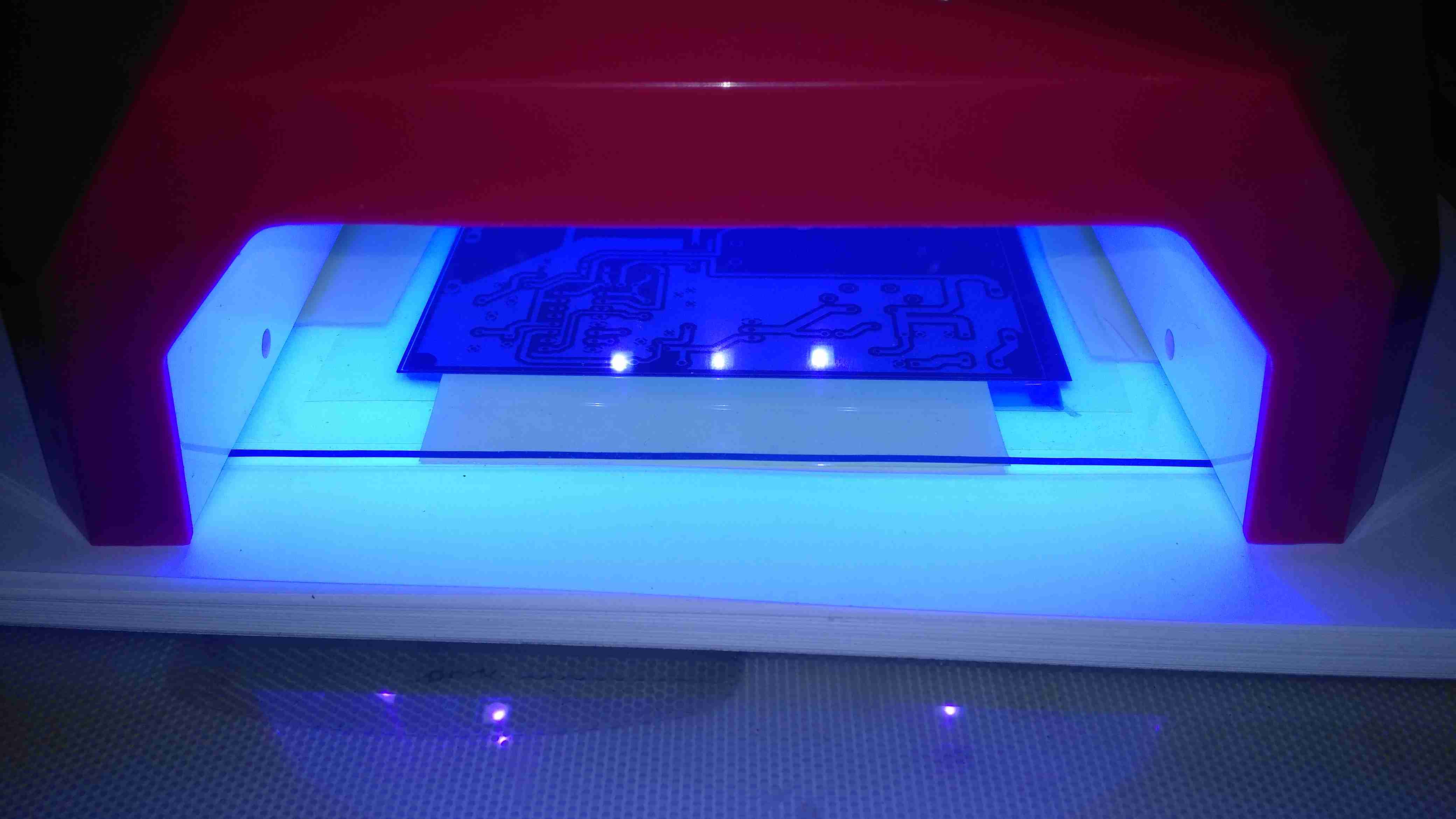
Exposing The PCB
The PCB is placed on a firm surface, the exposure mask lined up on top, and the whole thing covered with a sheet of standard glass to apply even pressure. The UV exposure lamp in this case is a cheap eBay UV nail curing unit, with 15 high power LEDs. (I’ll do a teardown on this when I get some time, it’s got some very odd LEDs in it). Exposing the board for 60 seconds is all the time needed.
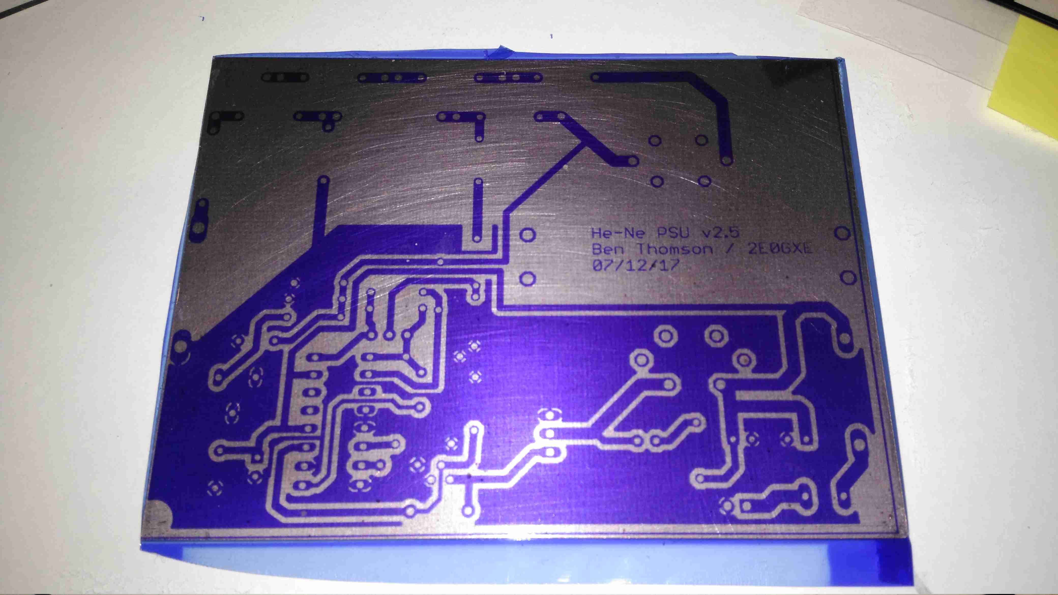
After Exposure
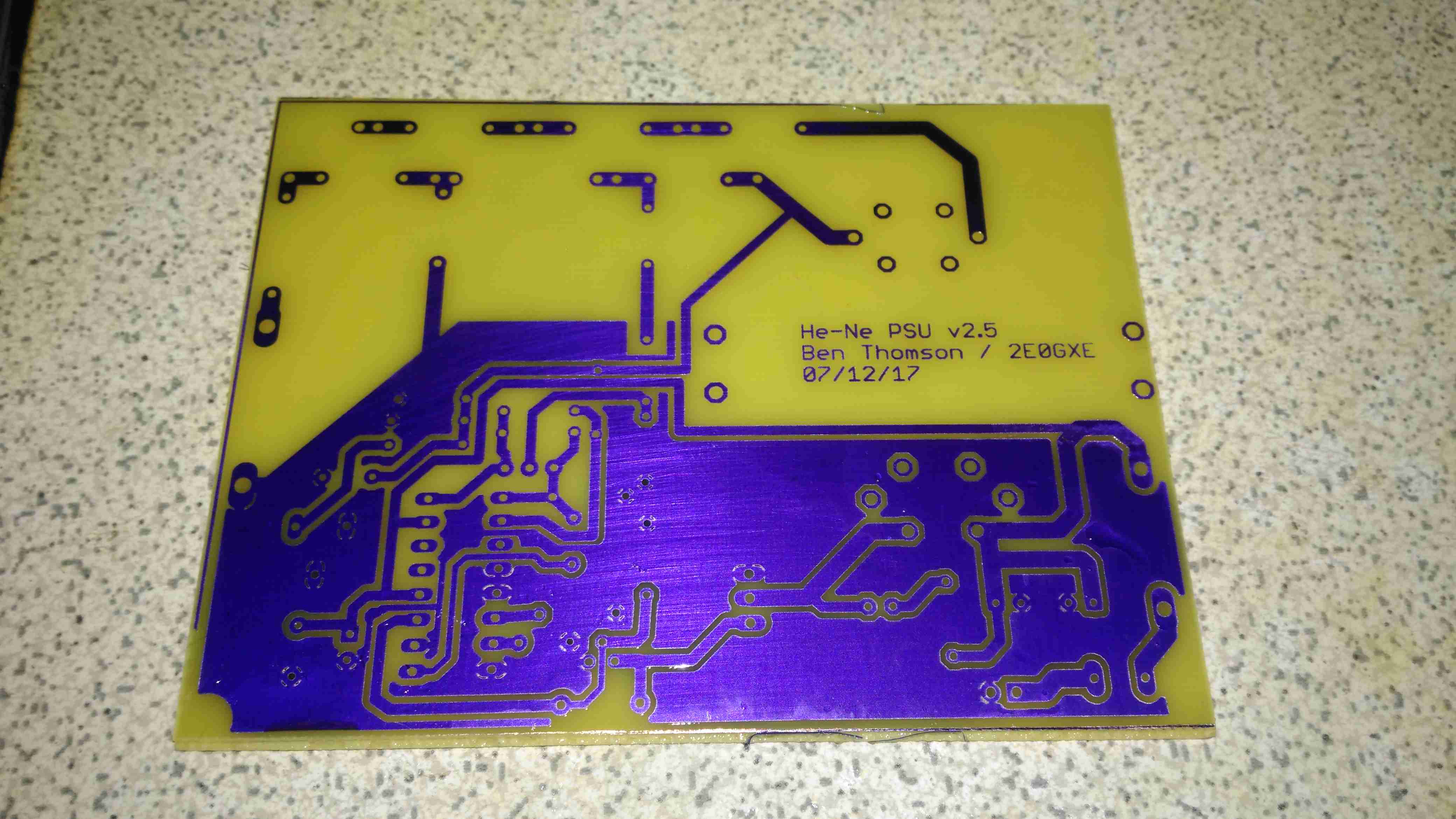
After the board is exposed, the areas that got hit with the UV light have turned purple – the resist has hardened in these areas. It’s bloody tough as well, I’ve scrubbed at it with some vigour and it doesn’t come off. Toner transfer was a bit naff in this respect, most of the time the toner came off so easily that the etchant lifted it off. After this step is done, the remaining protective film on the top can be removed.
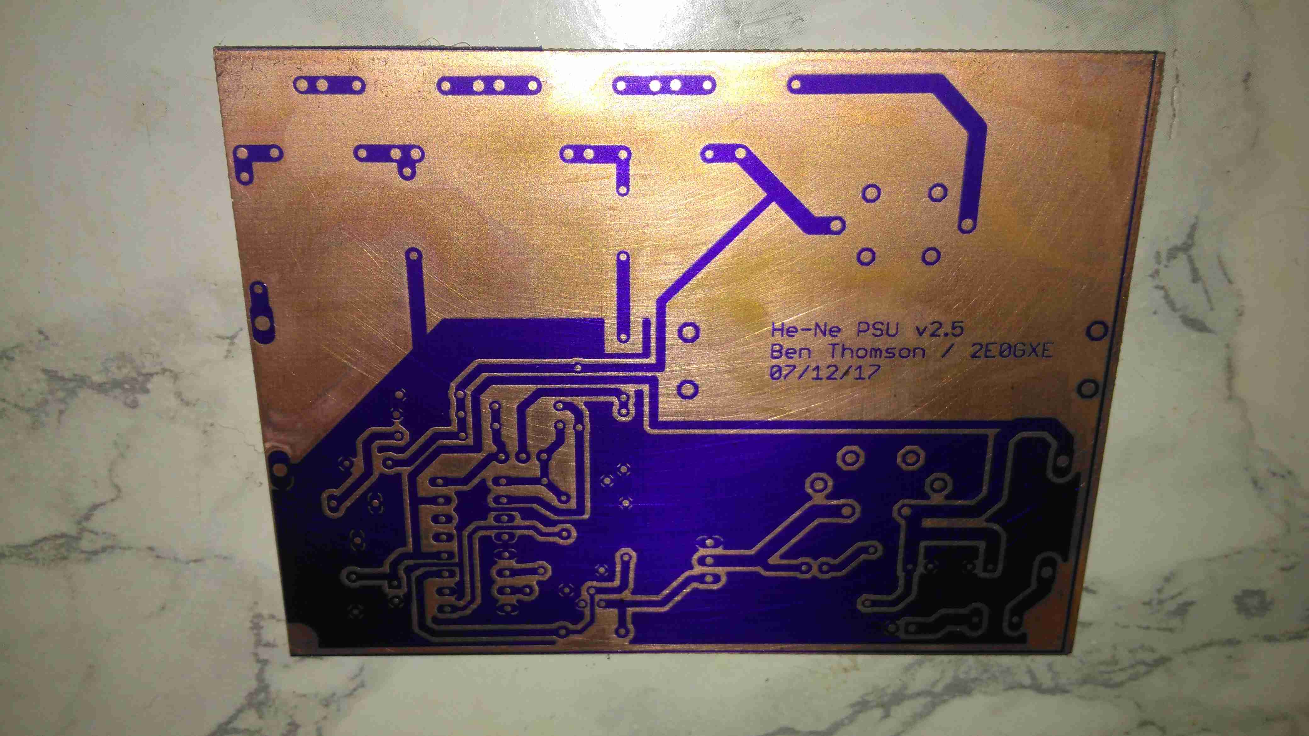
After Developing
The film is developed in a solution of Sodium Carbonate (washing Soda). This is mildly alkaline and it dissolves off the unexposed resist.
After Etching
Now it’s into the etching tank for a couple of minutes, I’m still using Ferric Chloride to etch my boards, at about 60°C. Etching at room temperature is much too slow. Once this is done, the board is washed, and then dipped in the strip tank for a couple of minutes. This is a Sodium Hydroxide solution, and is very caustic, so gloves are required for this bit. Getting Ferric Chloride on skin is also a fairly bad idea, it stains everything orange, and it attacks pretty much every metal it comes into contact with, including Stainless Steel.
This method does require some more effort than the toner transfer method, but it’s much more reliable. If something goes wrong with the exposure, it’s very easy to strip the board completely & start again before etching. This saves PCB material and etchant. This is definitely more suited to small-scale production as well, since the photomask can be reused, there’s much less waste at the end. The etched lines are sharper, much better defined & even with some more chemicals involved, it’s a pretty clean process. All apart from the Ferric Chloride can be disposed of down the sink after use, since the developer & stripper are just alkaline solutions.
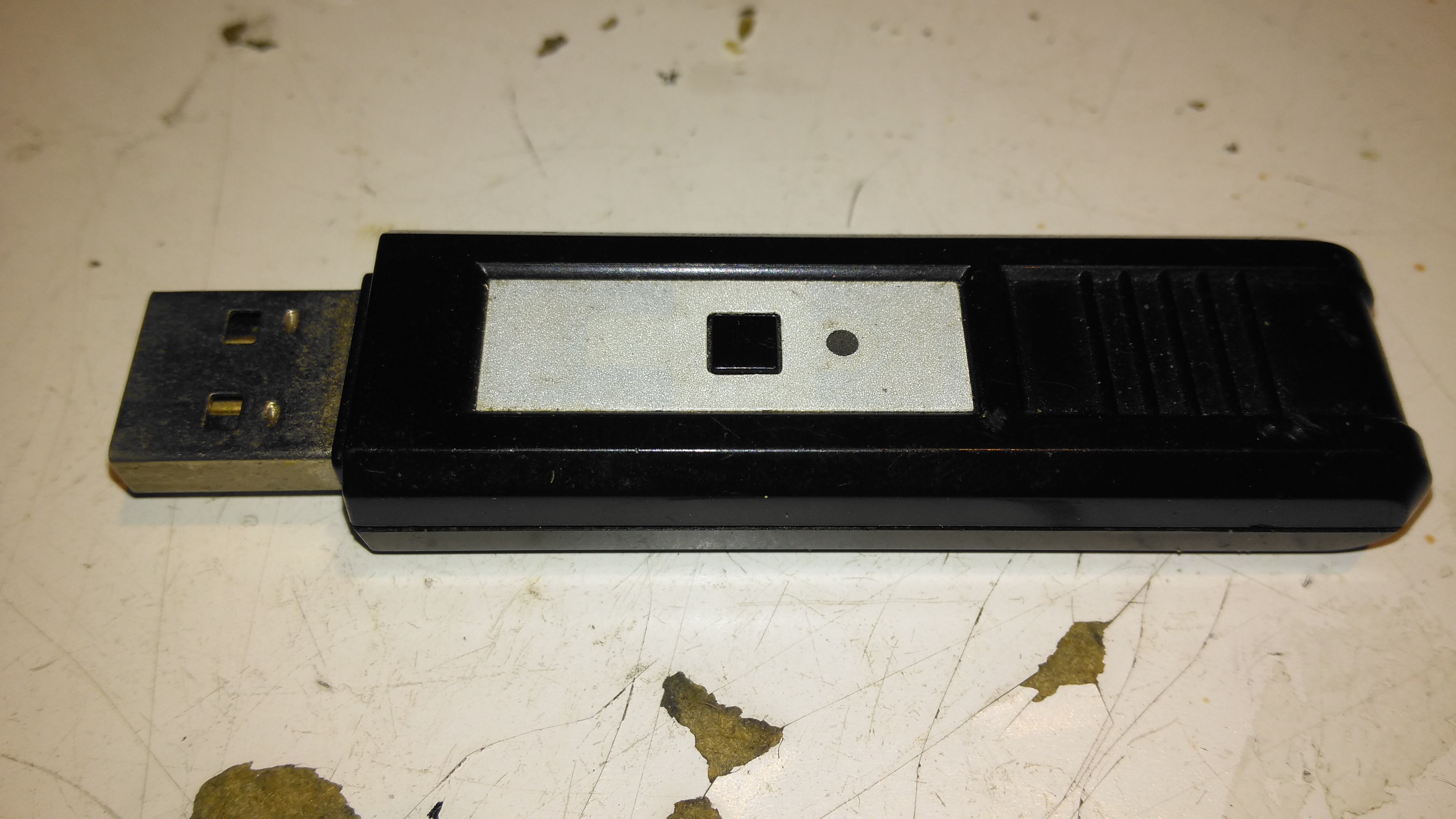
This is a pair of modules that Maplin was selling some time back, to send stereo audio over a 2.4GHz radio link. The transmitter identifies as a USB sound card, I’ve personally used these units to transmit audio about 60ft. The transmitter, above, has a single button for pairing with the receiver below.
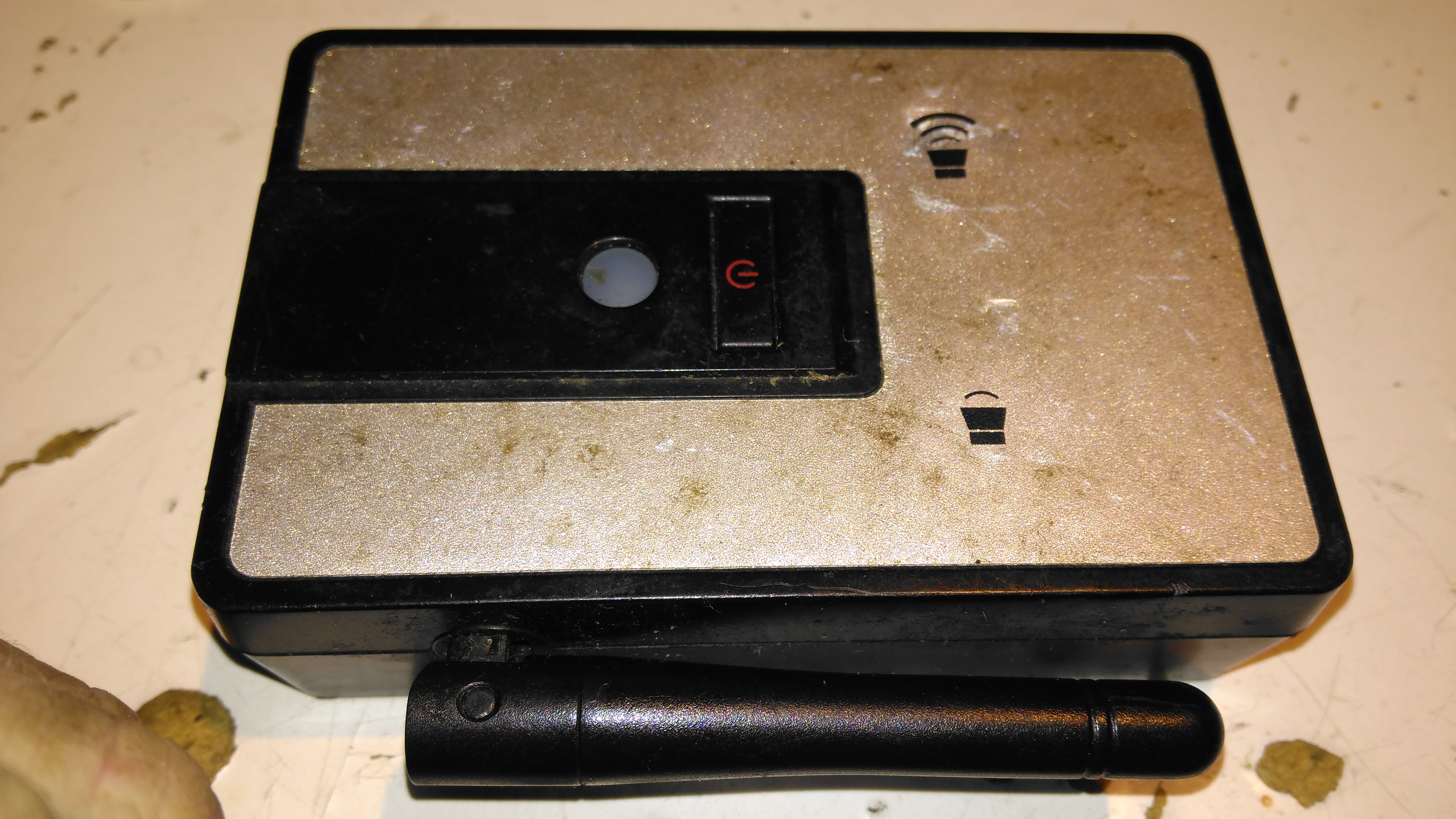
Receiver
The receiver unit has a large external antenna, a link status LED & volume buttons, these directly control the volume level on the host PC via the sound card drivers.
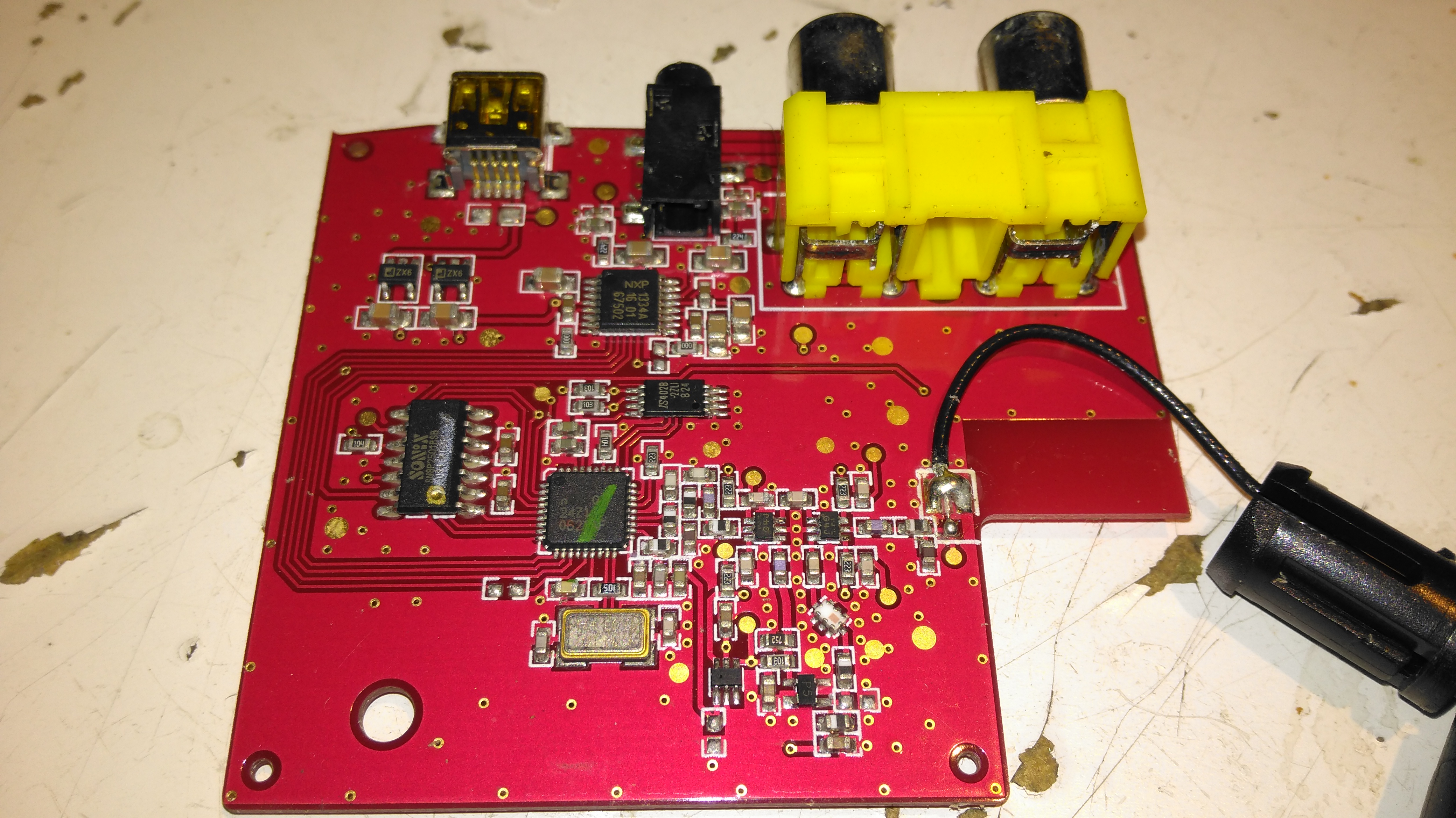
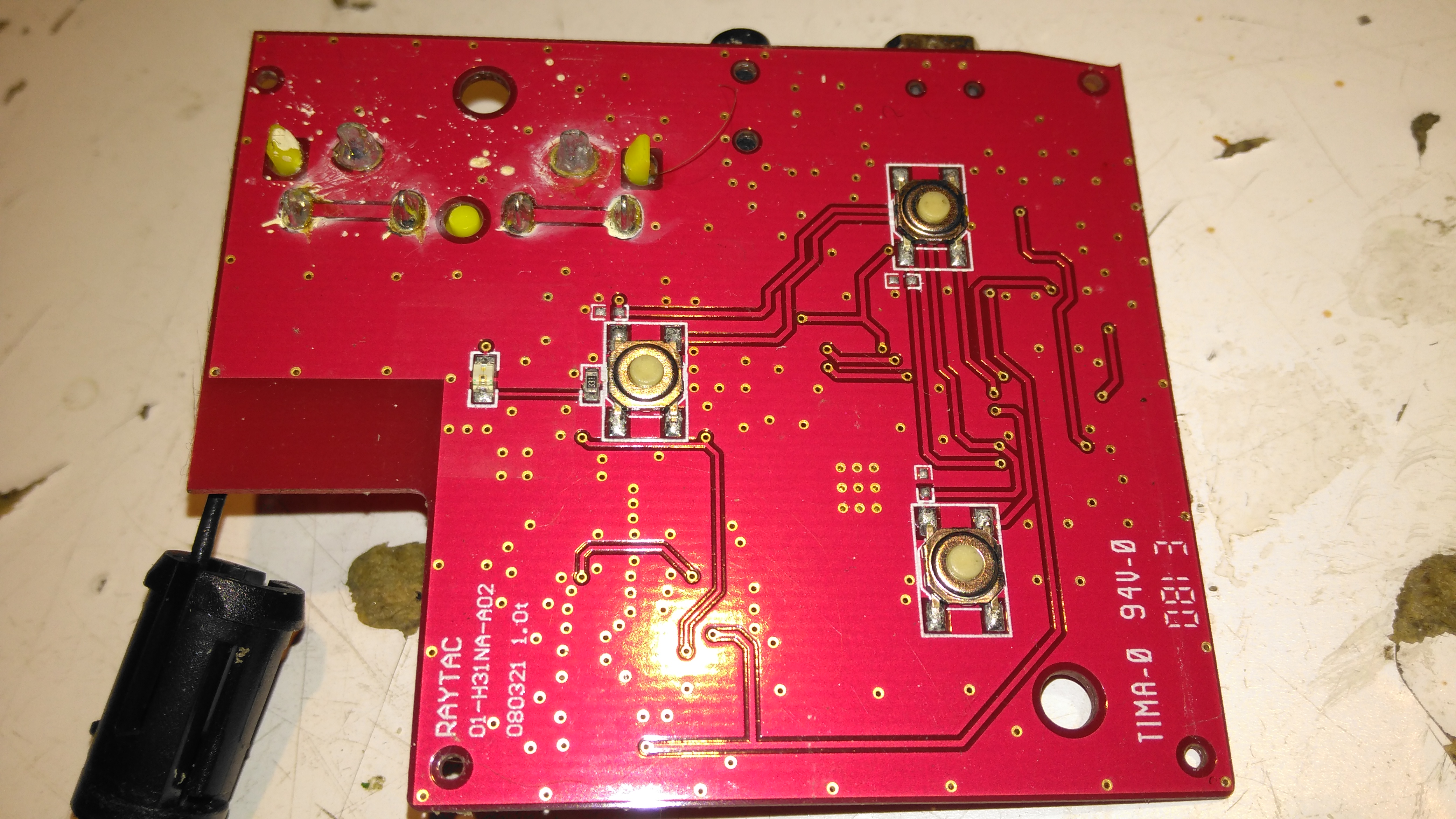
Receiver PCB Top
Popping the case open on the receiver reveals a large PCB, holding the chipset, along with the audio output jacks & Mini-USB power input. The antenna Coax is soldered to the PCB.
Receiver PCB Bottom
The top of the board has the control buttons, and the status LED.
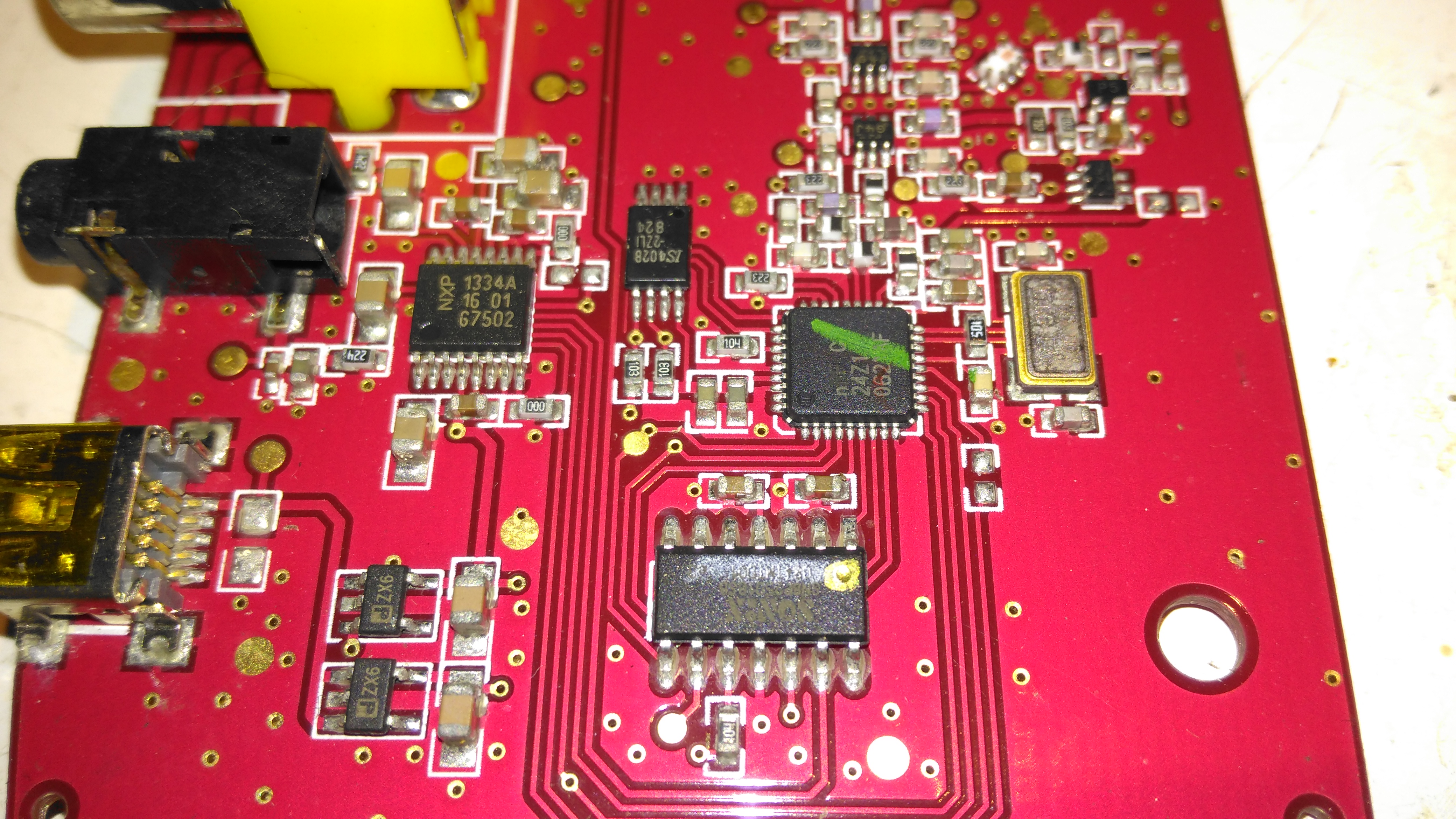
Receiver Chipset
The chipset used here is a Nordic Semiconductor nRF20Z01 2.4GHz Stereo Audio Streamer, there’s a small microcontroller which does all the register magic on the RF transceiver. The RF chain is at the top of the photo, audio outputs on the top left, and the micro USB power input & voltage regulators at bottom left.
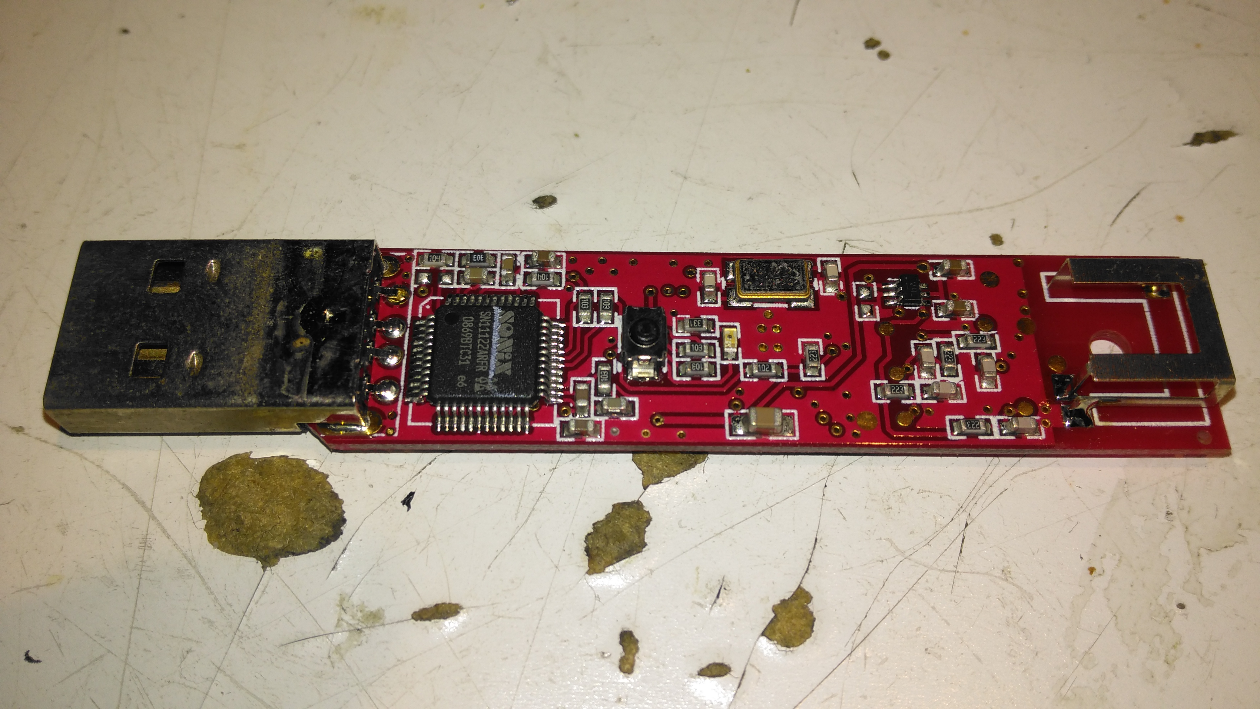
Transmitter PCB Top
The transmitter PCB has a Sonix USB Audio Codec, to interface with the host PC. This is then fed into another Nordic Semi part on the opposite side of the board:
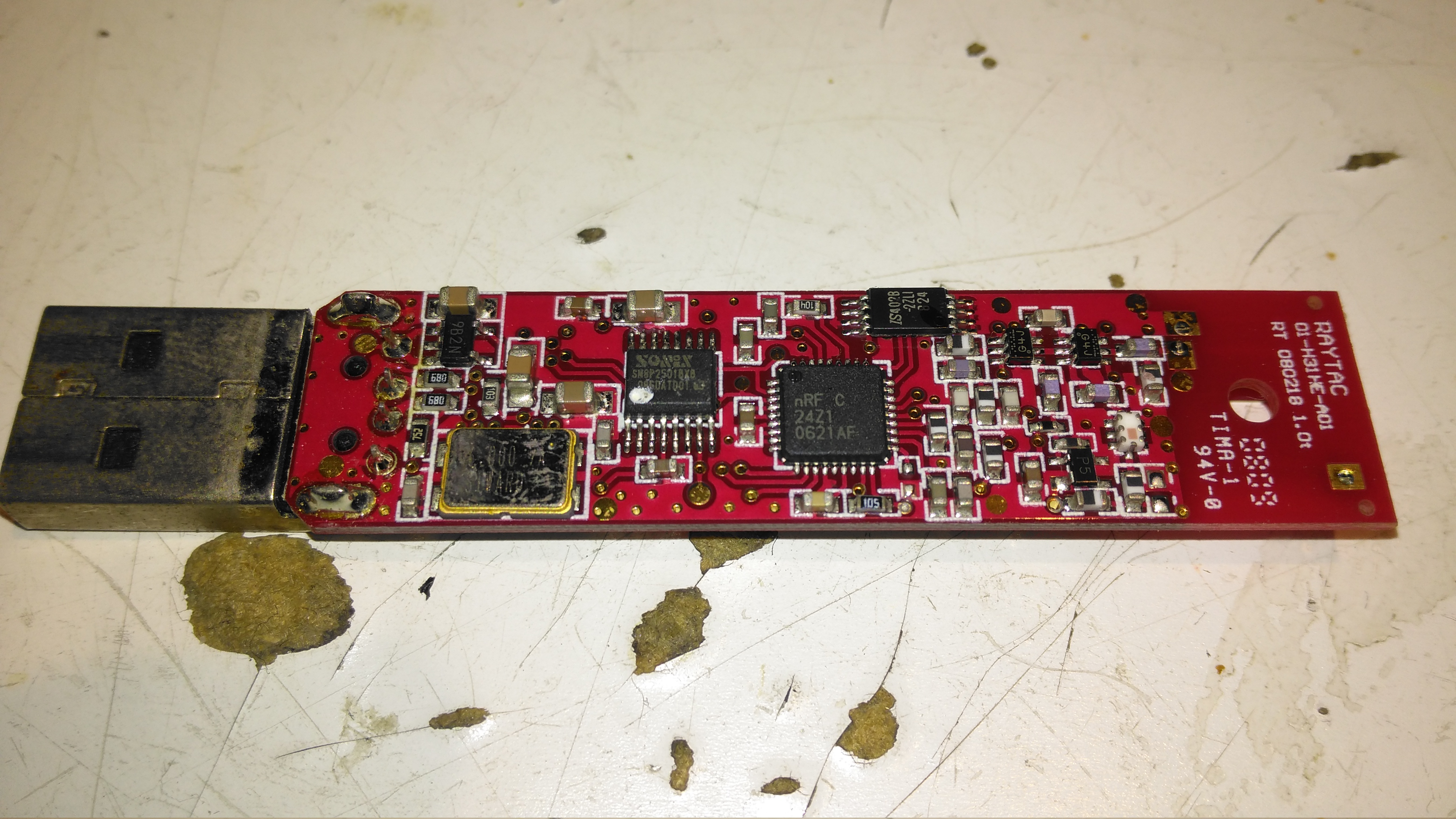
Transmitter PCB Bottom
The bottom of the transmitter has the RF section, and another small control microcontroller.
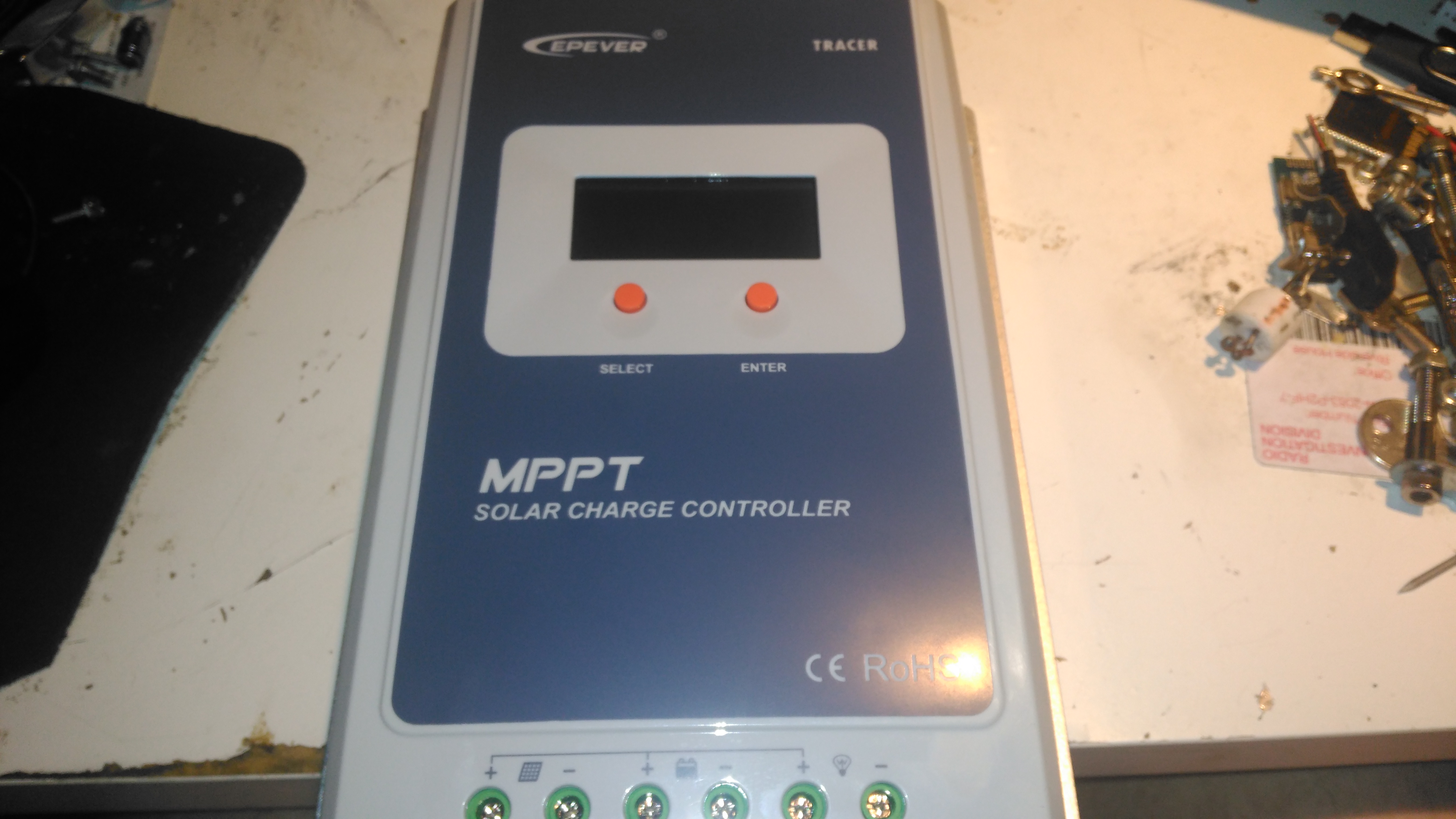
Here’s the solar charge controller to go with the MT50 from the last post. This is the 40A version of the EpEver Tracer A series, the 4210A. This unit is large, and very heavy. Most of this weight comes from the enormous heatsink which doubles as the mounting plate for all the other components, and the large inductors that are going to be required for the DC-DC conversion that MPPT requires.
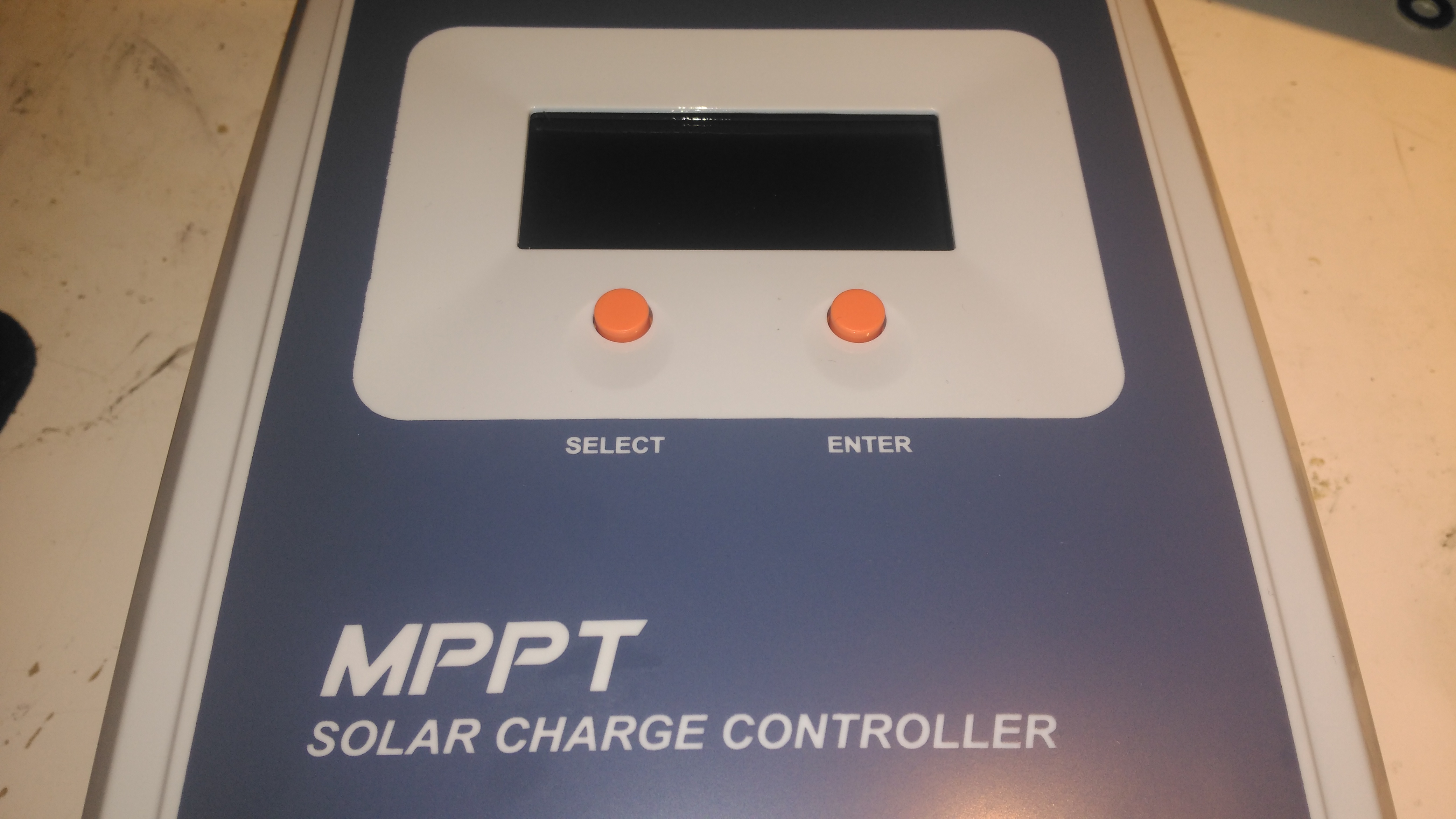
Front Panel
The front panel has a basic LCD, which shows various stats, such as PV Volts & Amps, and battery bank Volts & Amps. The pair of buttons are used to navigate the basic menu to configure some options, along with switching the load terminals ON/OFF.
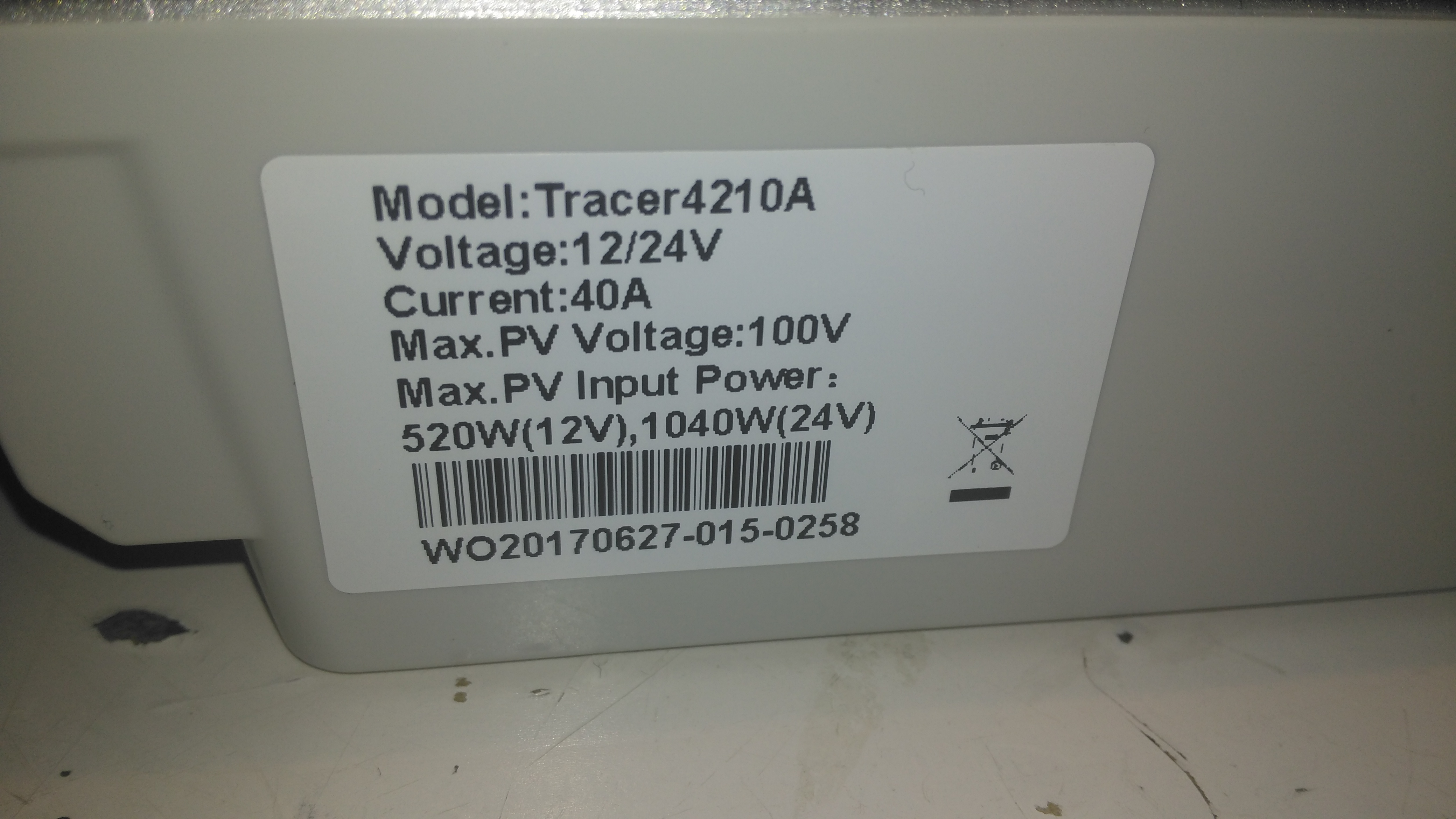
Specifications
There’s a specs label on the top, with a slight difference here vs the manual, which states the max. PV volts as 92v.
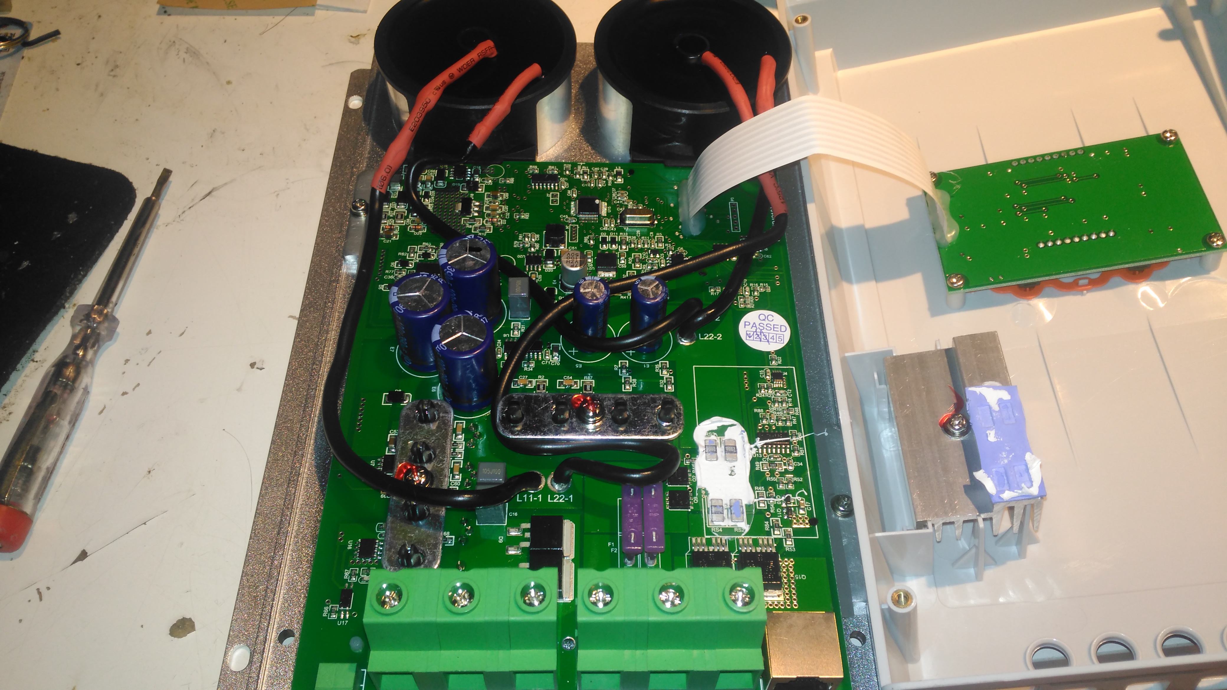
Main PCB Overview
Removing 4 machine screws from the bottom of the unit allows the top to come off. Like the MT50 remote panel, this unit also has moulded-in brass thread inserts in the plastic parts. The PCB in here is heavily comformal coated, which stops me from reading the laser-etched numbers on the semiconductor devices, so there will be few details there.
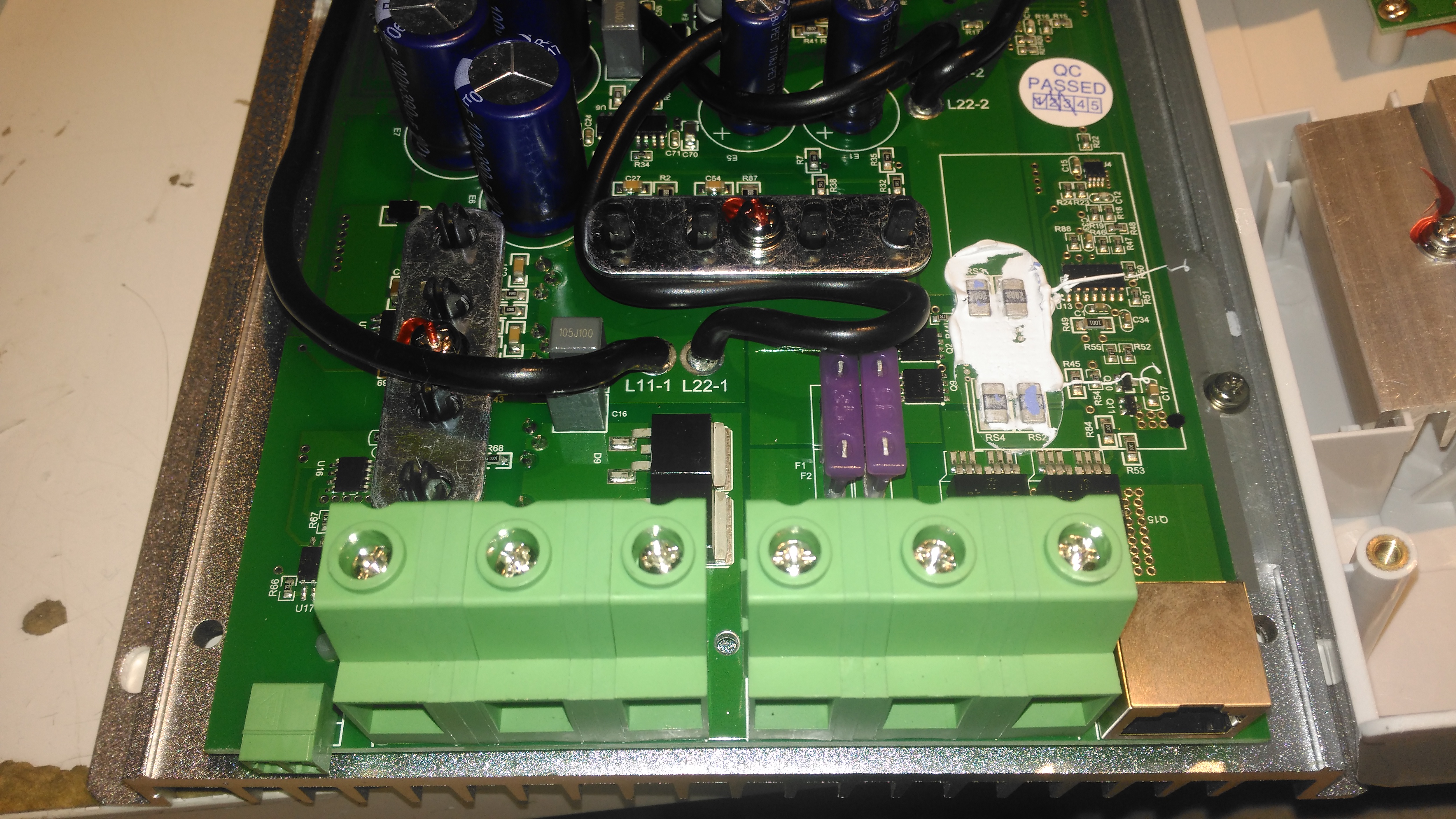
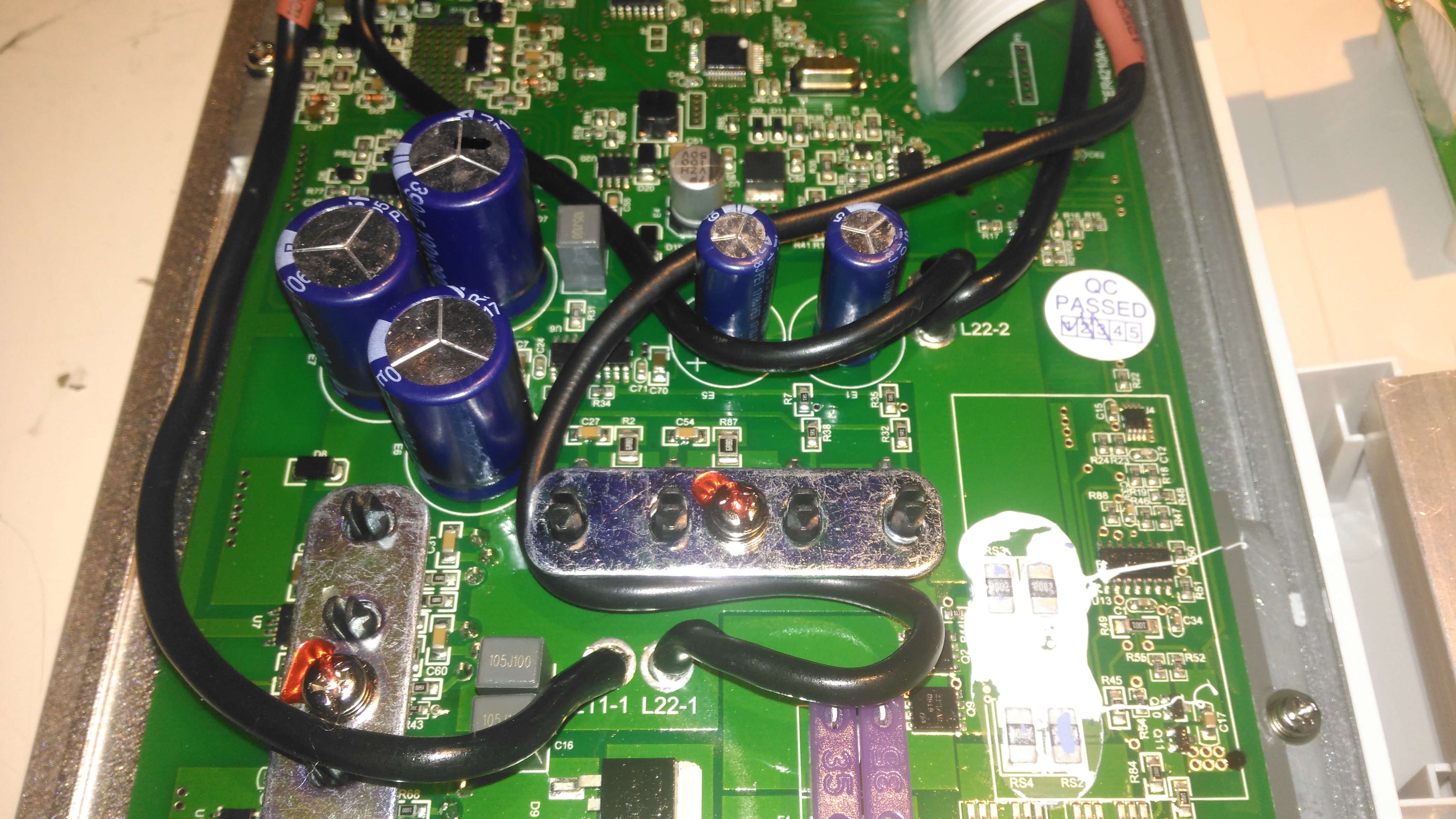
Main PCB Lower
Here’s the bottom section of the main PCB, with the enormous screw terminals, which will easily take cables up to about 16mm². The RJ-45 jack which hosts the unit’s RS-485 bus is to the right, and a smaller 2-pin connector on the left sorts out the battery temperature sensor.
The DC output MOSFET switches are hiding just behind the right-hand terminals, there’s a pair of them in this unit to handle the output current. Some beefy diodes polarity-protect both the battery & PV inputs.
Board Centre
Moving up the board shows two 35A automotive blade fuses soldered into the board – these would be a real pain to replace if they ever blew, however with the electronic load current protection built into this unit, it’s an unlikely situation, unless something went hideously wrong. The main switching devices for the DC-DC converter are hidden – they’re clamped to the heatsink with the bars at right angles in the photo, I’m not going to dig any deeper into this just for those though – they’re just TO220 devices.
Under a load of thermal gunk on the right are 4 current shunt resistors, and the amplifiers for reading their values. These 1206-size SMD resistors looked a bit small for the power rating to me, but they’re heatsinked in operation to a small heatsink mounted in the top cover.
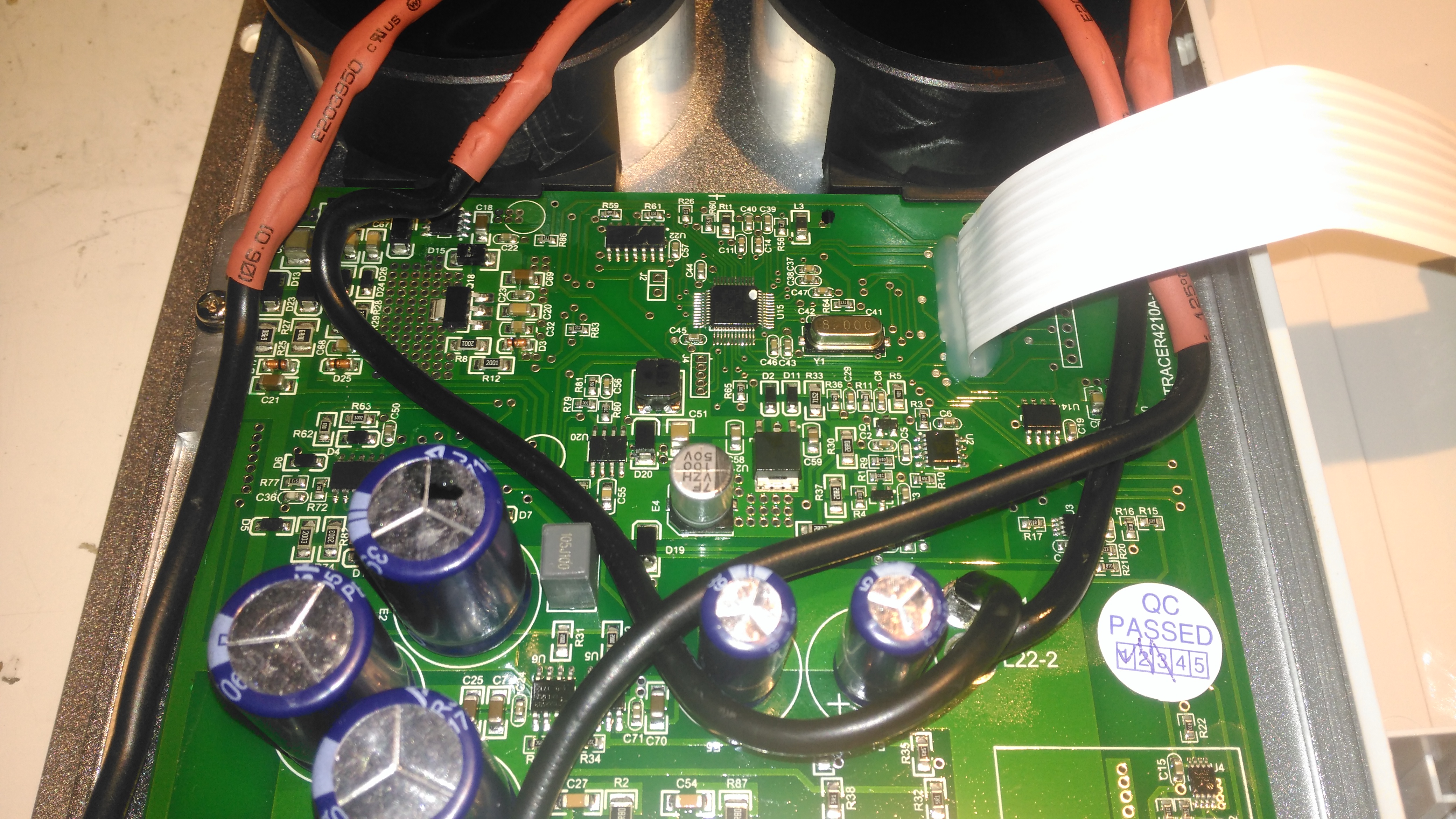
Board Upper
The upper section of the PCB hosts the main microcontroller, and the connections over to the front panel LCD & buttons. Couldn’t really get much info from these chips, due to the conformal coating.
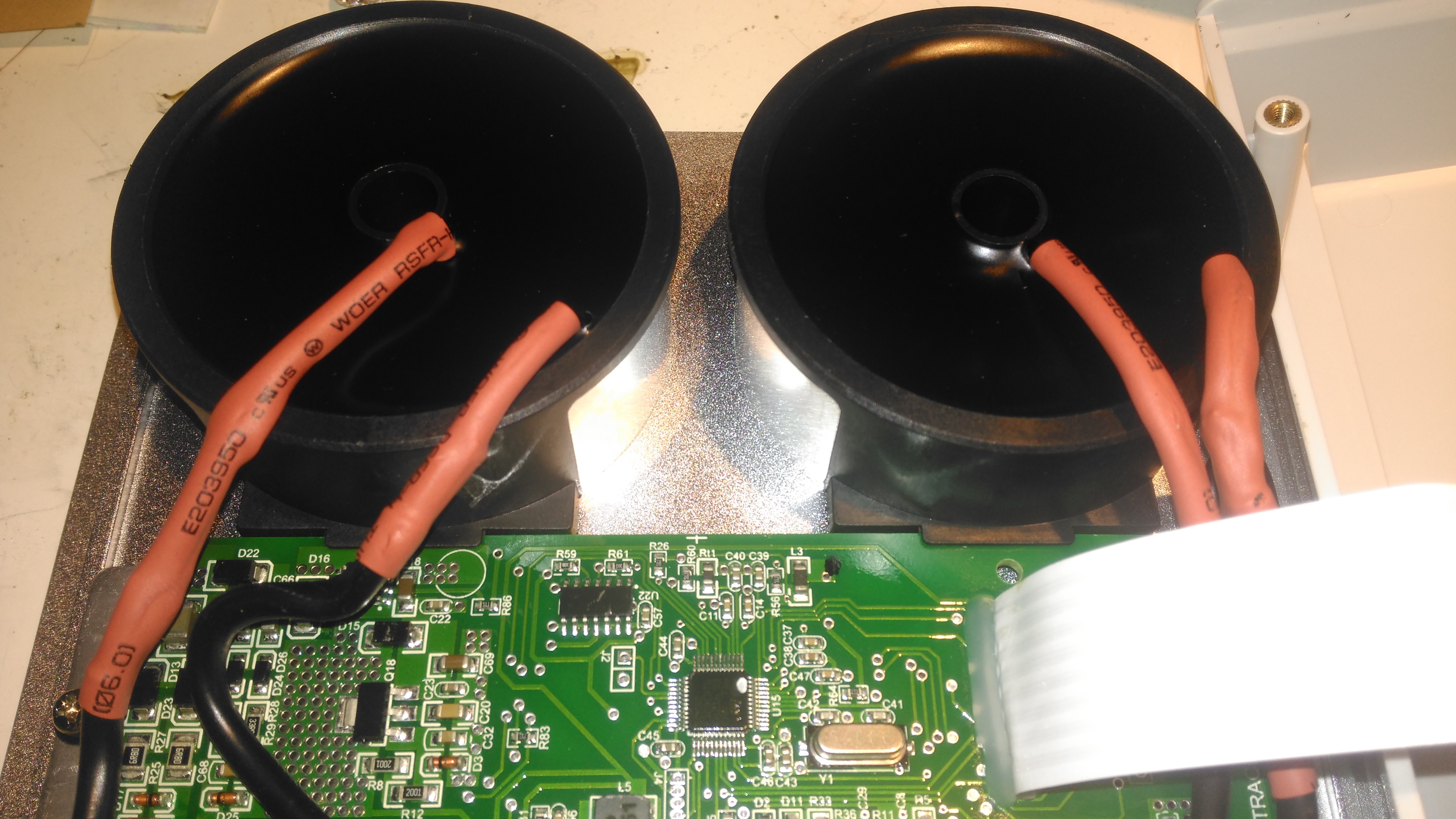
Toroidal Inductors
Right at the top of the unit are these toroidal inductors, potted into aluminium housings. The copper windings of these is very heavy – at least 2.5mm². They’re electrically in parallel, the 20A version would only have a single inductor.
Current Shunt Heatsink
This small heatsink sits inside the top cover, and provides some cooling to the current shunts.
Display Board
Not much to say for the display board, there’s going to be nothing here apart from an I²C LCD driver & the pair of front panel buttons, so I won’t bother removing this from the case.
So it’s time to get the propulsion system underway for the trolley, a pair of wheelchair motors were sourced for this, from HacMan. Since I don’t know how many hours are on these units, or how they’ve been treated in the past, I’m going to do a full service on them to ensure reliability. I decided on wheelchair motors due to their extreme ruggedness & heavily built components – this project when complete is going to weigh in at about 150kg!
I suspected something was amiss with one of the motors from running them under no load: the left hand wheelchair motor was heating up to the point of being too hot to touch, so this one at the very least needed some investigation.
Motor Disassembly & Assessment
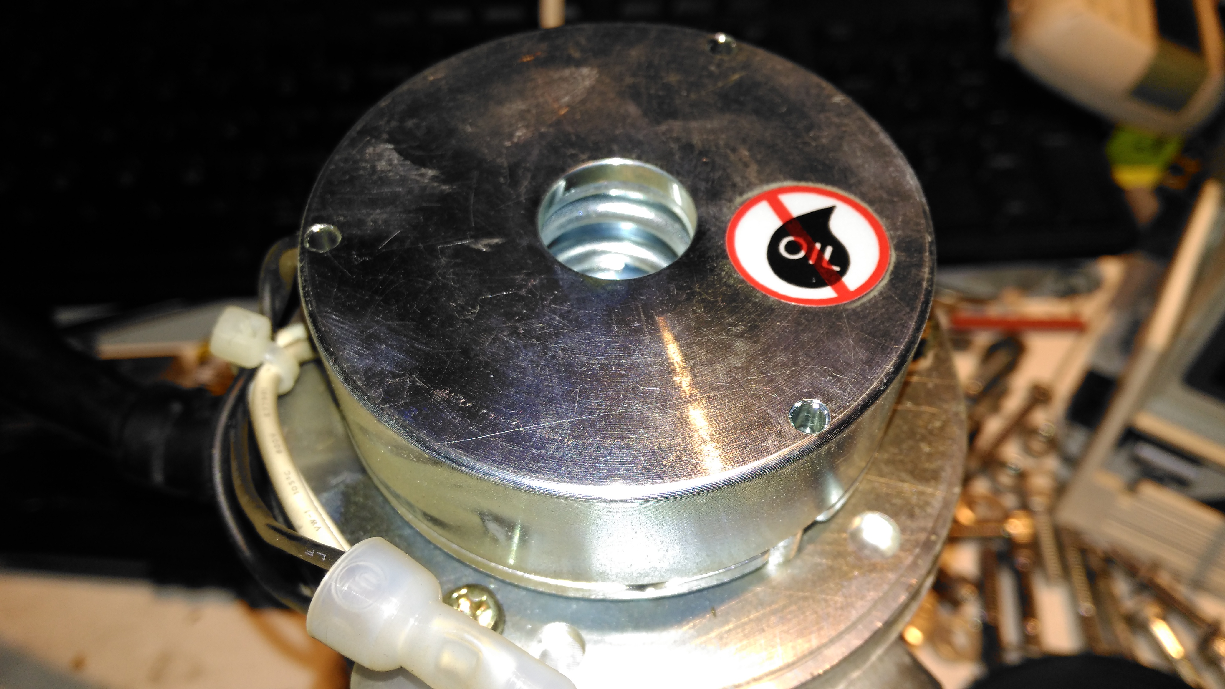
Rear Cover Removed
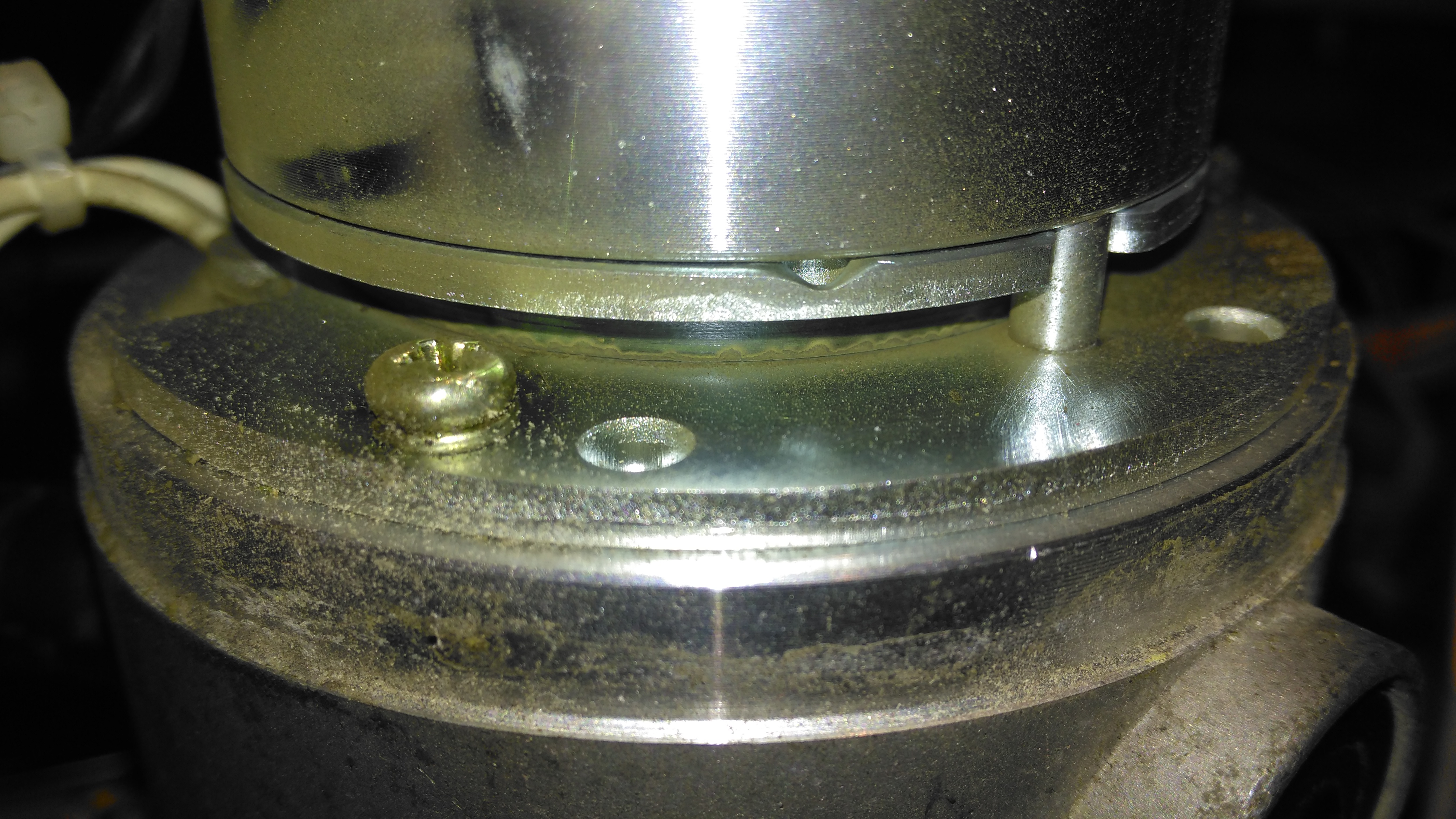
With the back cover removed from the motor the electromagnetic brake is revealed. This engages when power is removed to stop the motor freewheeling, which even though it’s a wormdrive box, it will do readily if backdriven.
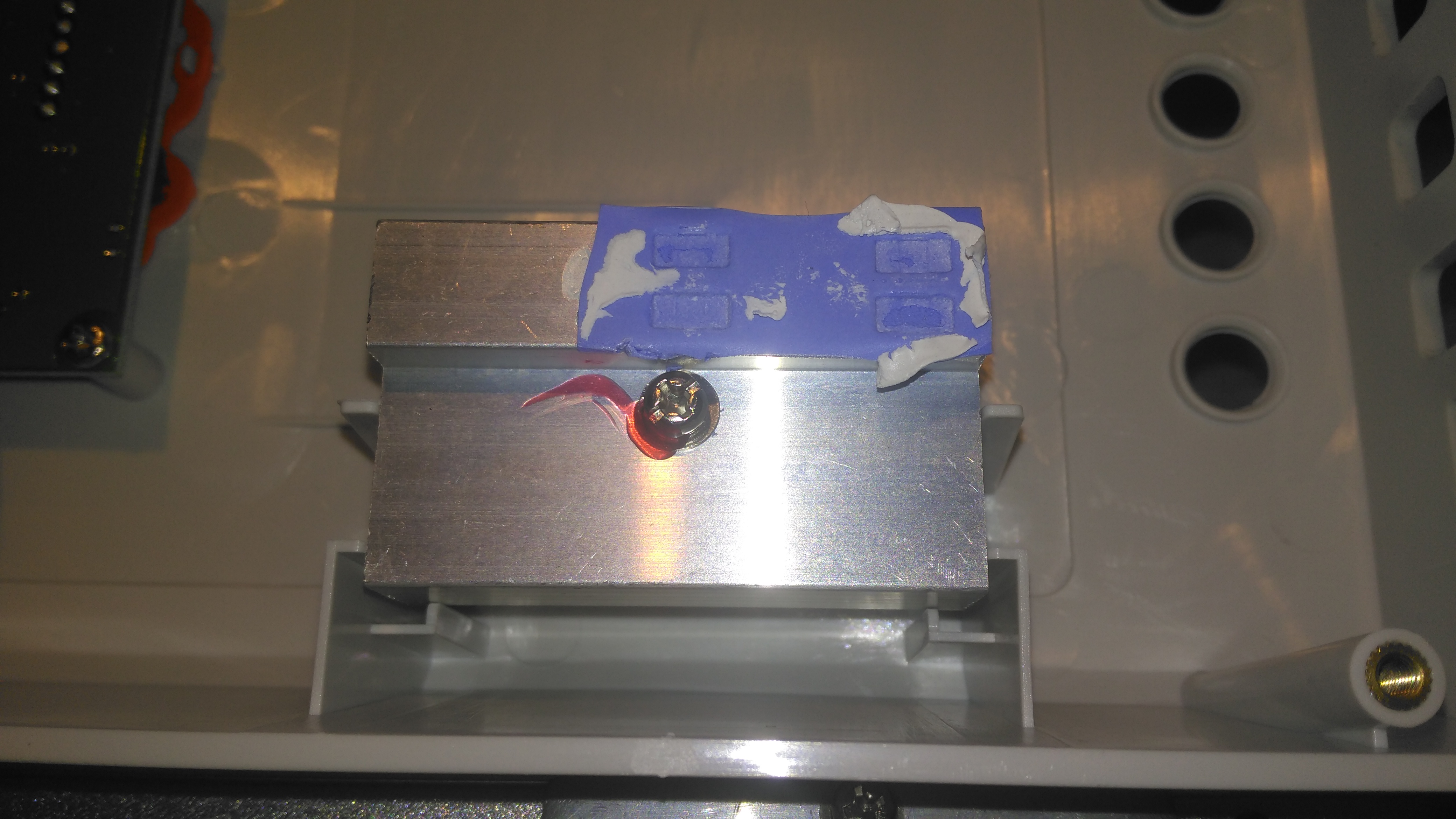
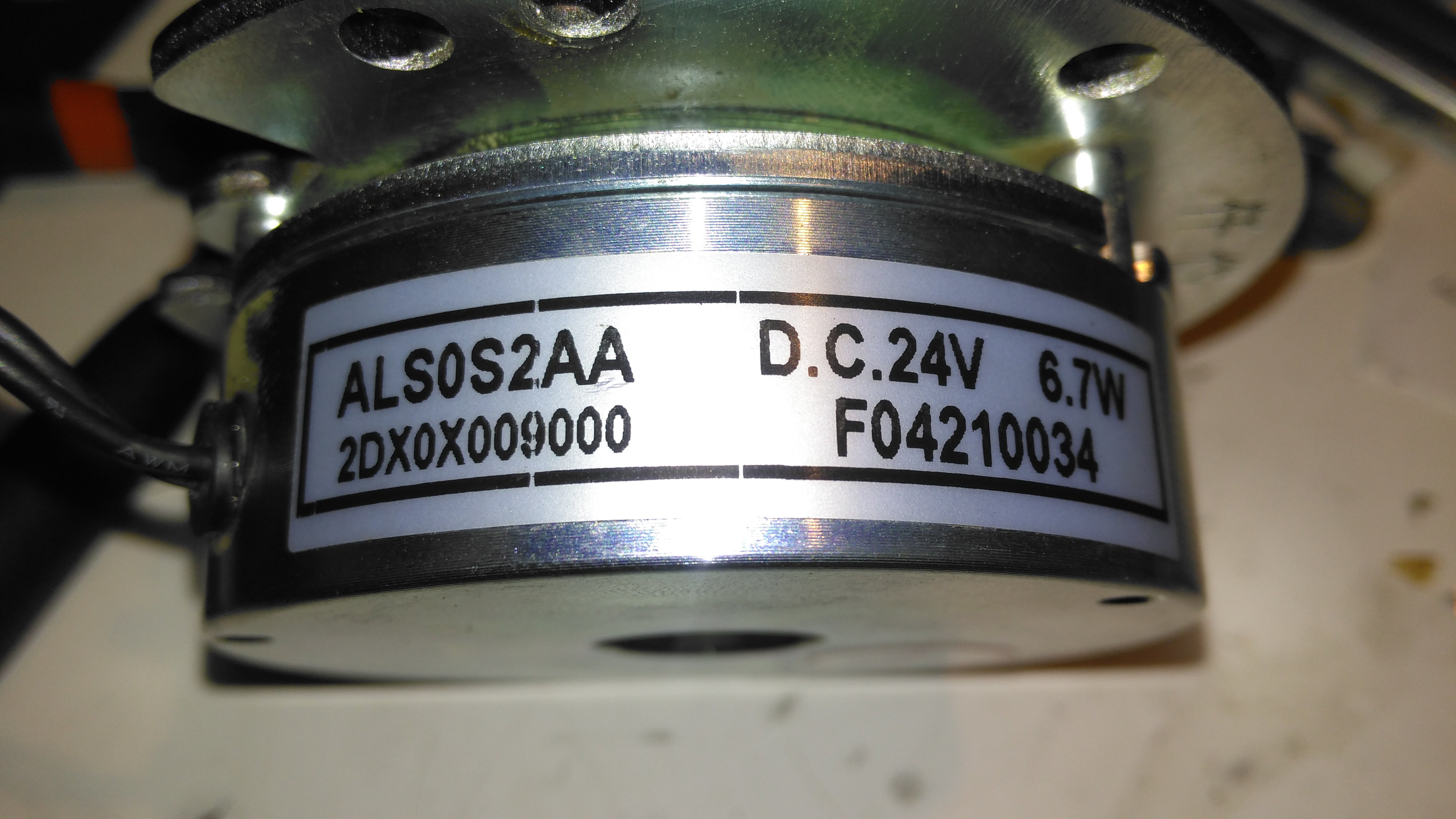
Electromagnetic Brake Assembly
The brake is rated 6.7W at 24v DC.
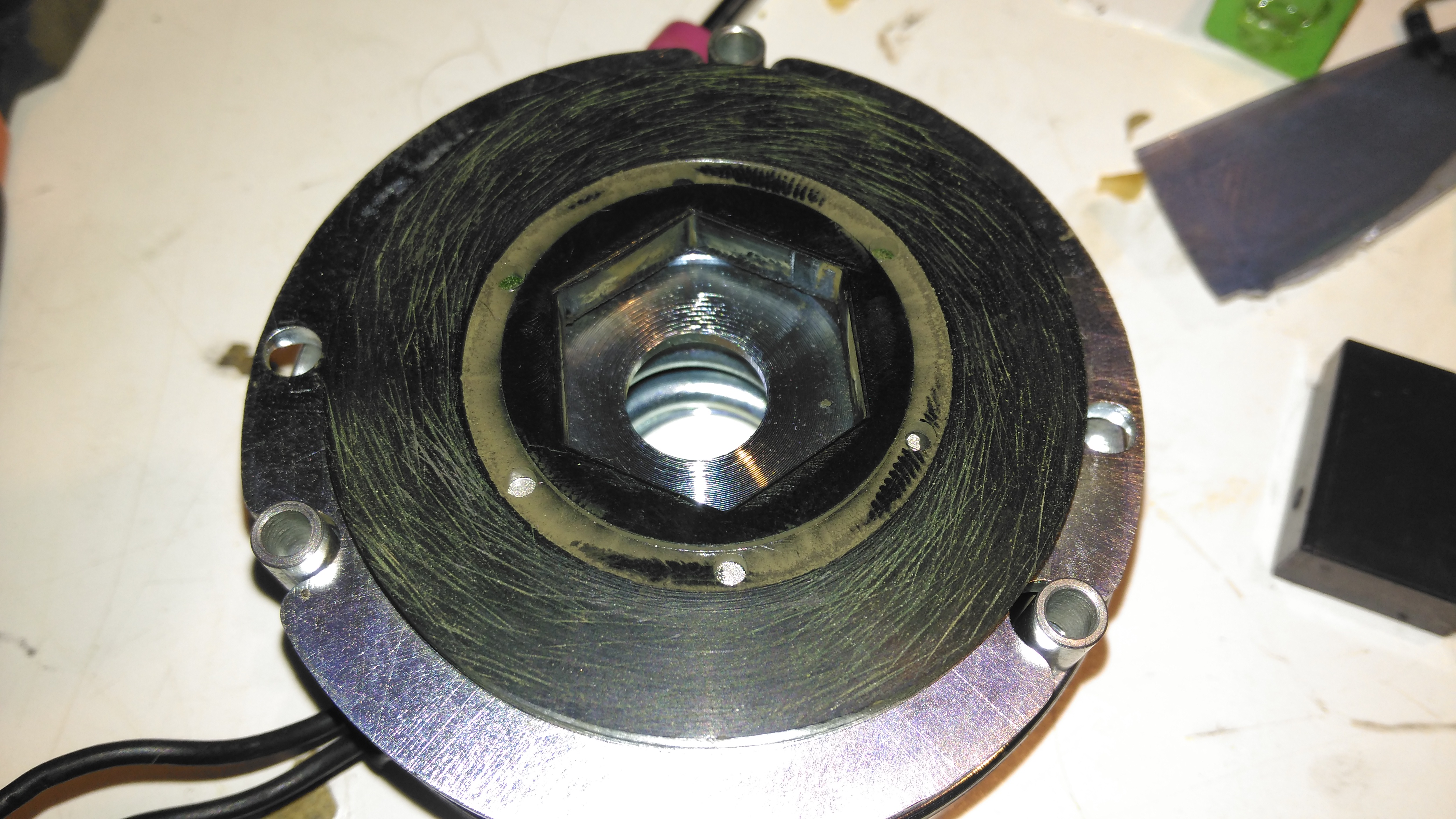
Brake Disc
The brake disc is just visible between the plates of the brake here, with some green dust worn off the disc. When power is applied, the top disc, just under the magnet on top, is pulled upward against spring pressure away from the brake disc, which is attached to the motor armature.
Brake Disc
Here’s the brake disc, removed from the motor. There’s only a little wear here, as I’d expect – these brakes don’t engage until the motors have come to a complete stop.
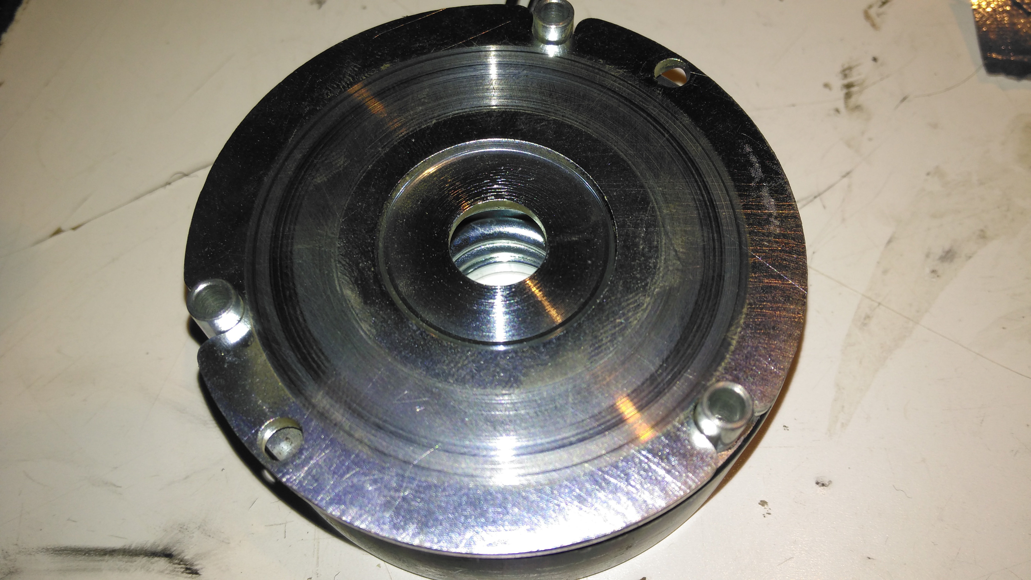
Brake Actuator
The steel disc above the magnet acts as one of the friction surfaces of the brake.
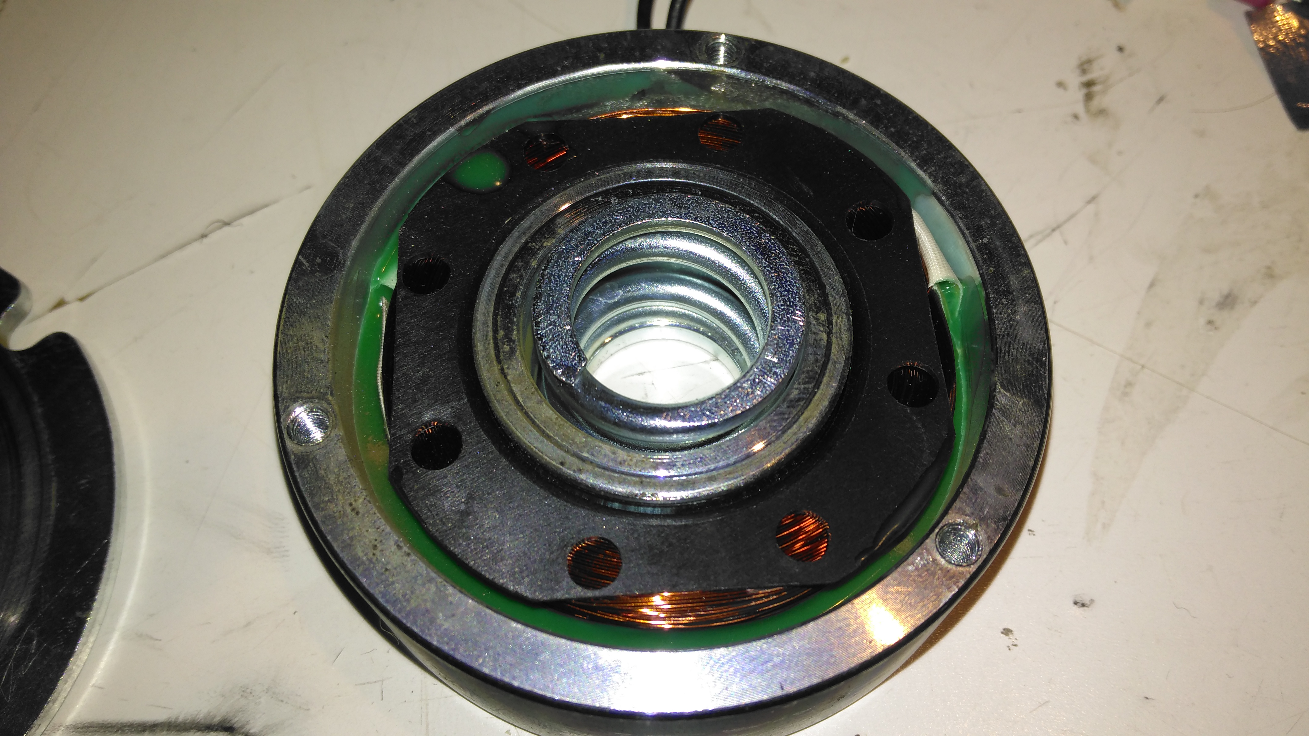
Brake Solenoid
Finally, the solenoid is at the back, partially potted in resin. The strong coil spring in the centre applies the brakes when power is disconnected.
Gearbox Grok
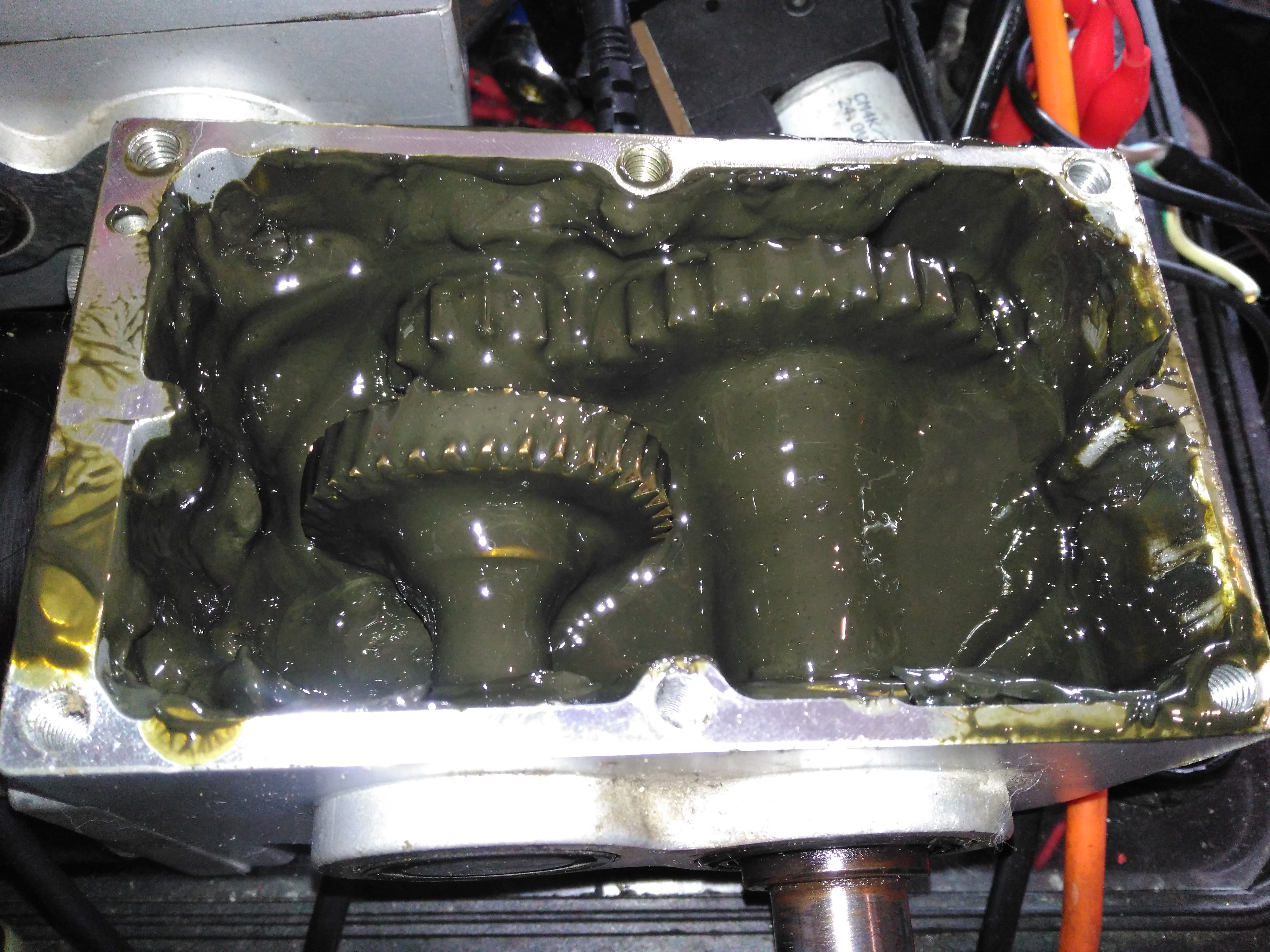
Removing the top of the gearbox reveals the state of the internals – There’s no wear at all on the gearset, but the lubricant is totally manky. The external oil seals have been leaking for some time, letting water in and grease out. The emulsified result is revolting! These gearboxes have a wormdrive first stage, the worm gear is underneath the left hand gearset. Steel spur gears then do the final gearing to the output shaft. The output gear is splined onto the output, and can slide along the shaft out of mesh – this is the freewheel clutch mechanism. At the moment it’s all obscured by the disgusting lubricant.
Input Shaft Seal
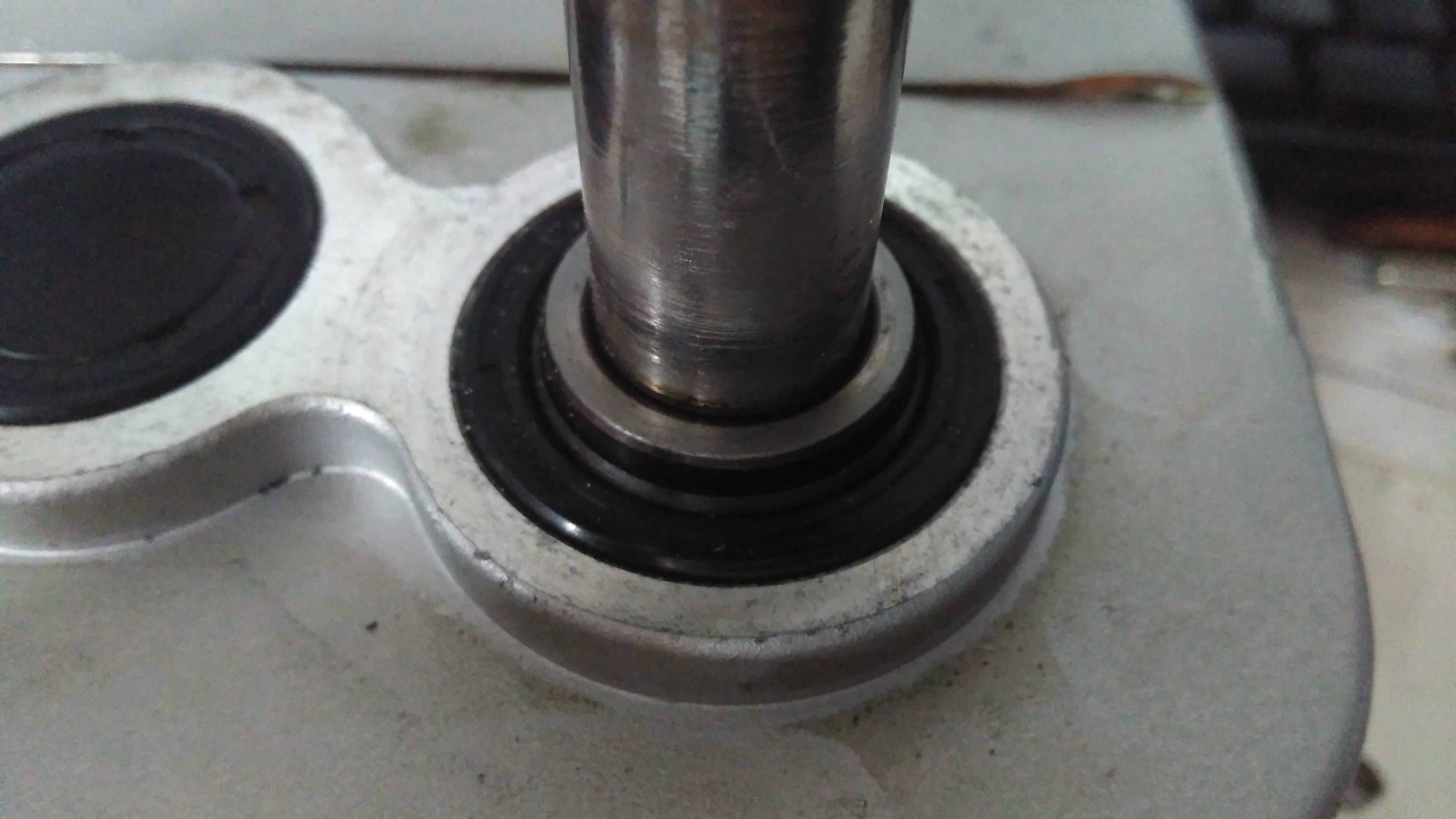
Here’s the failed seal on the left hand gearbox, the face damage was done by petrol immersion to clean everything up. (The seal is already compromised, so I’m not fussed about solvents eating the remaining rubber). The motor shaft is joined to the gearbox input by a rubber coupling.
Output Shaft Seal
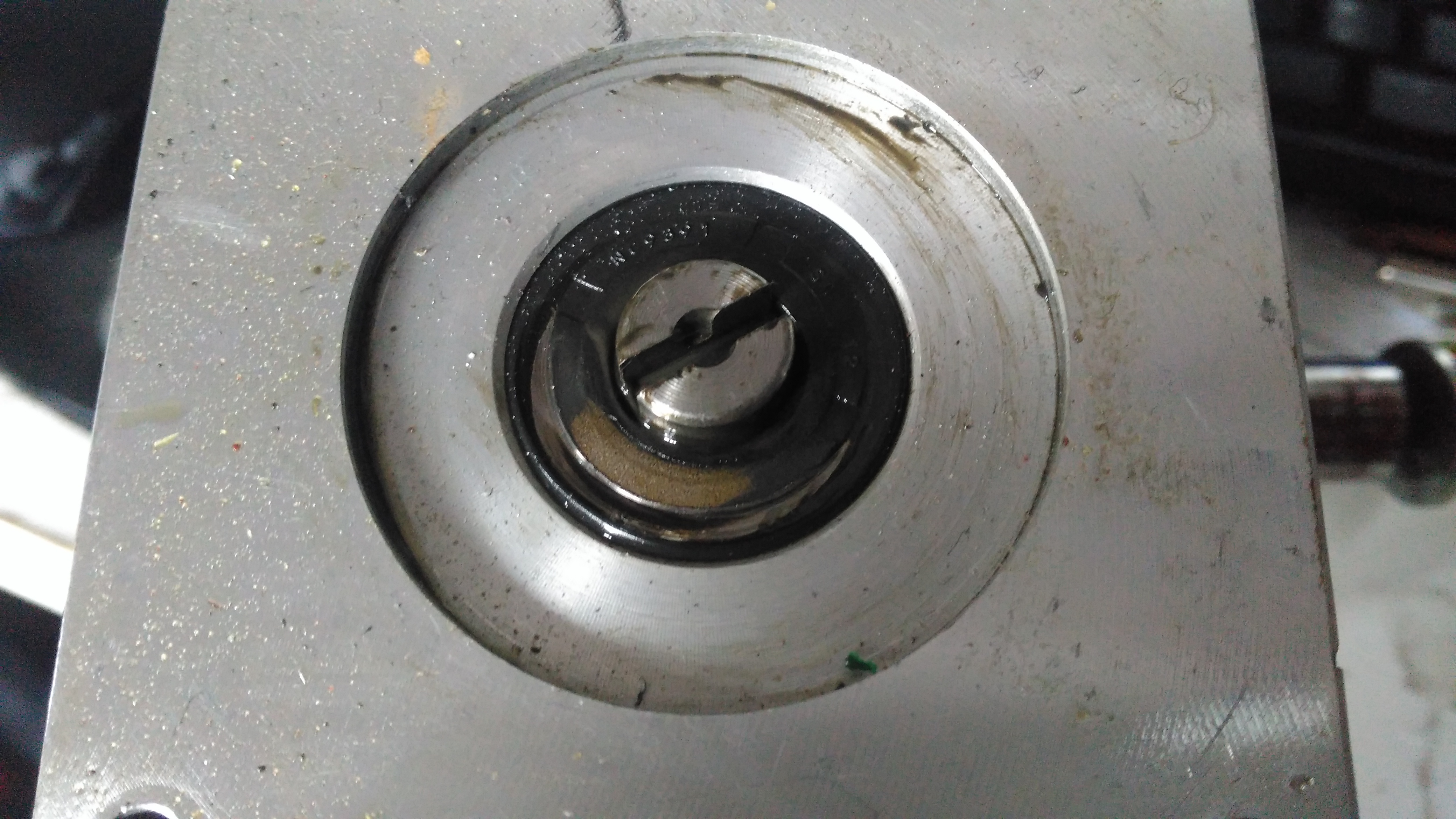
The output shaft seals seem to be still OK, there has been some seepage past the collar that the shaft rides in, but nothing more. This can be resealed with some Loctite bearing sealant. The sleeve is held into the gearbox by the wheel hub when in operation, but this doesn’t seal the gap unfortunately. I don’t know why the manufacturer didn’t just machine the shaft to that larger diameter, instead of using an extra sleeve to accommodate the seal.
Bore Seals
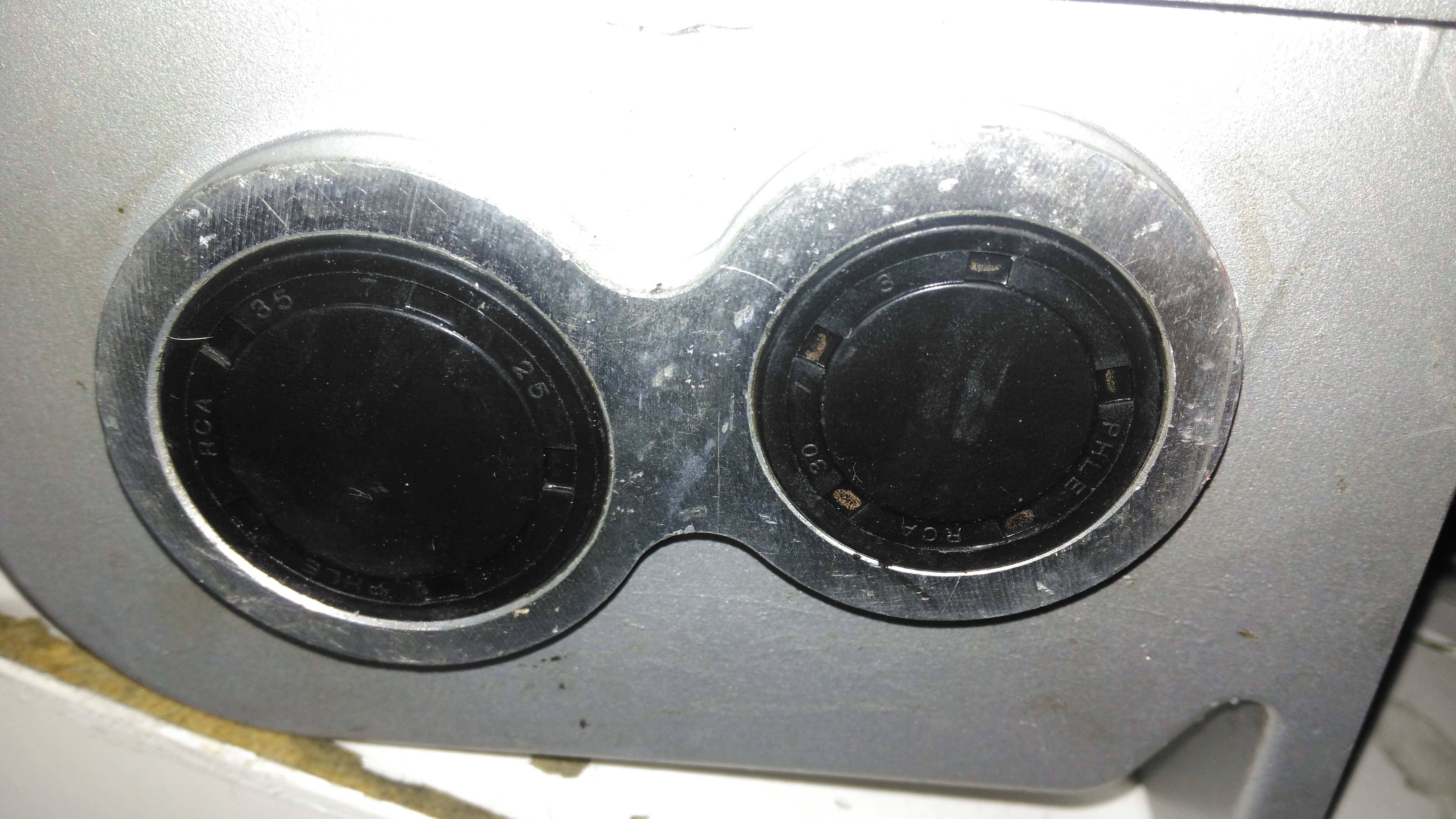
The bore seals covering the ends of the shafts are also fine, which is a good thing, since I can’t seem to find replacements for these anywhere. The input shaft seals will be replaced on both gearboxes though.
Motor Contamination
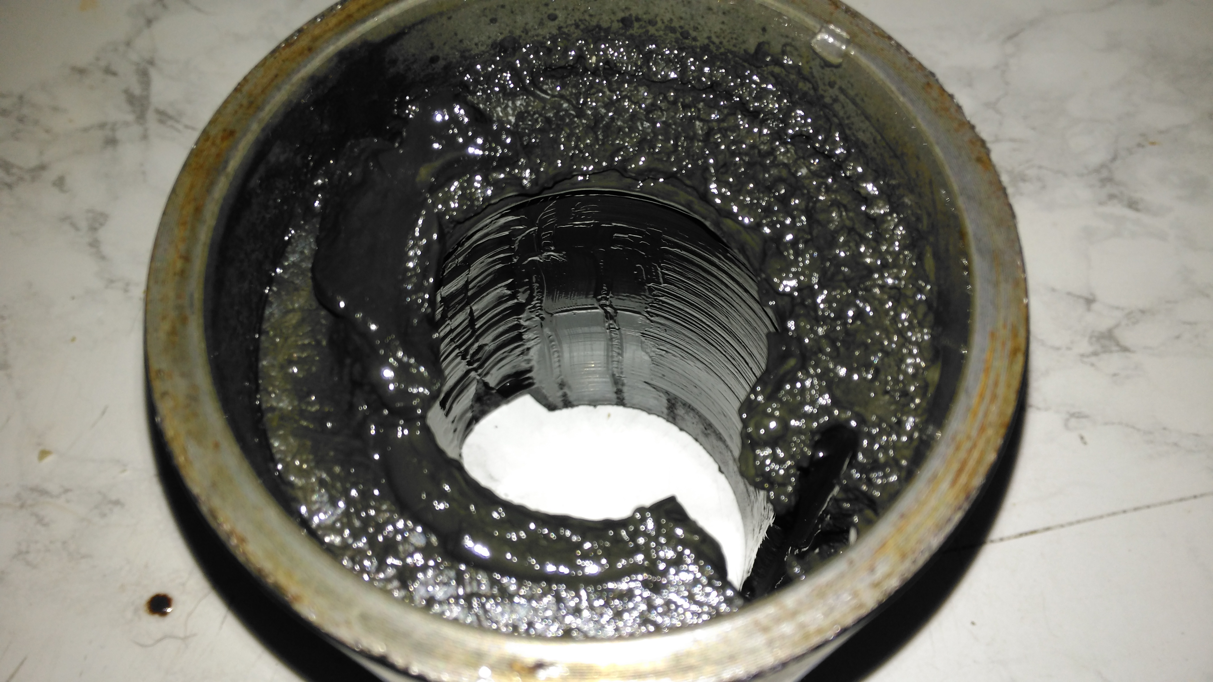
The oil seal must have been leaking for a long while! This is the gearbox end of the wheelchair motor frame, completely clogged with grease. Luckily only a small amount has made it down past the armature to the brushgear.
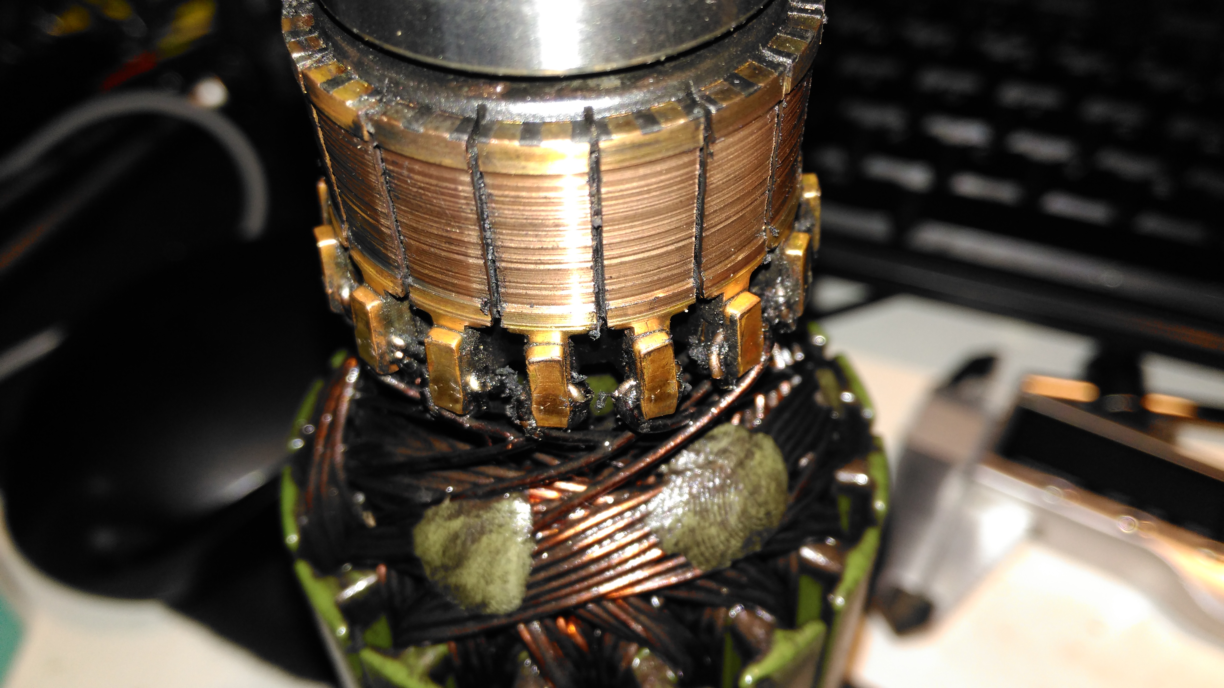
Damaged Commutator
The commutator of this motor is badly damaged, and the brushes are very worn. This has been caused by the gearbox oil seal failing, and contaminating the motor internals with lubricant. The undercut between the segments is all but gone – filled with an abrasive mixture of brush dust, copper dust & old lubricant. Some repair work will be required here.
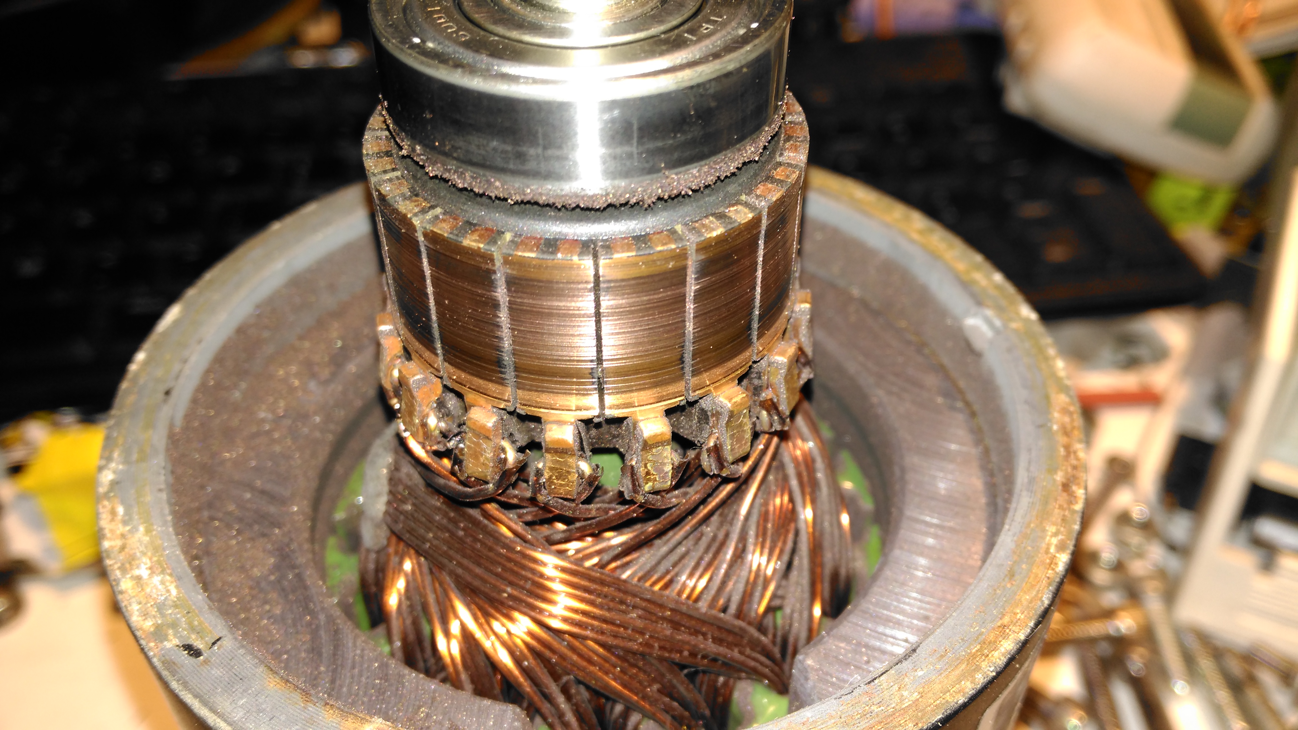
Second Motor
Here’s the brushgear removed from the second wheelchair motor, this one looks much more normal, and there’s not as much wear on the brushes or the commutator. Just the usual coating of brush dust.
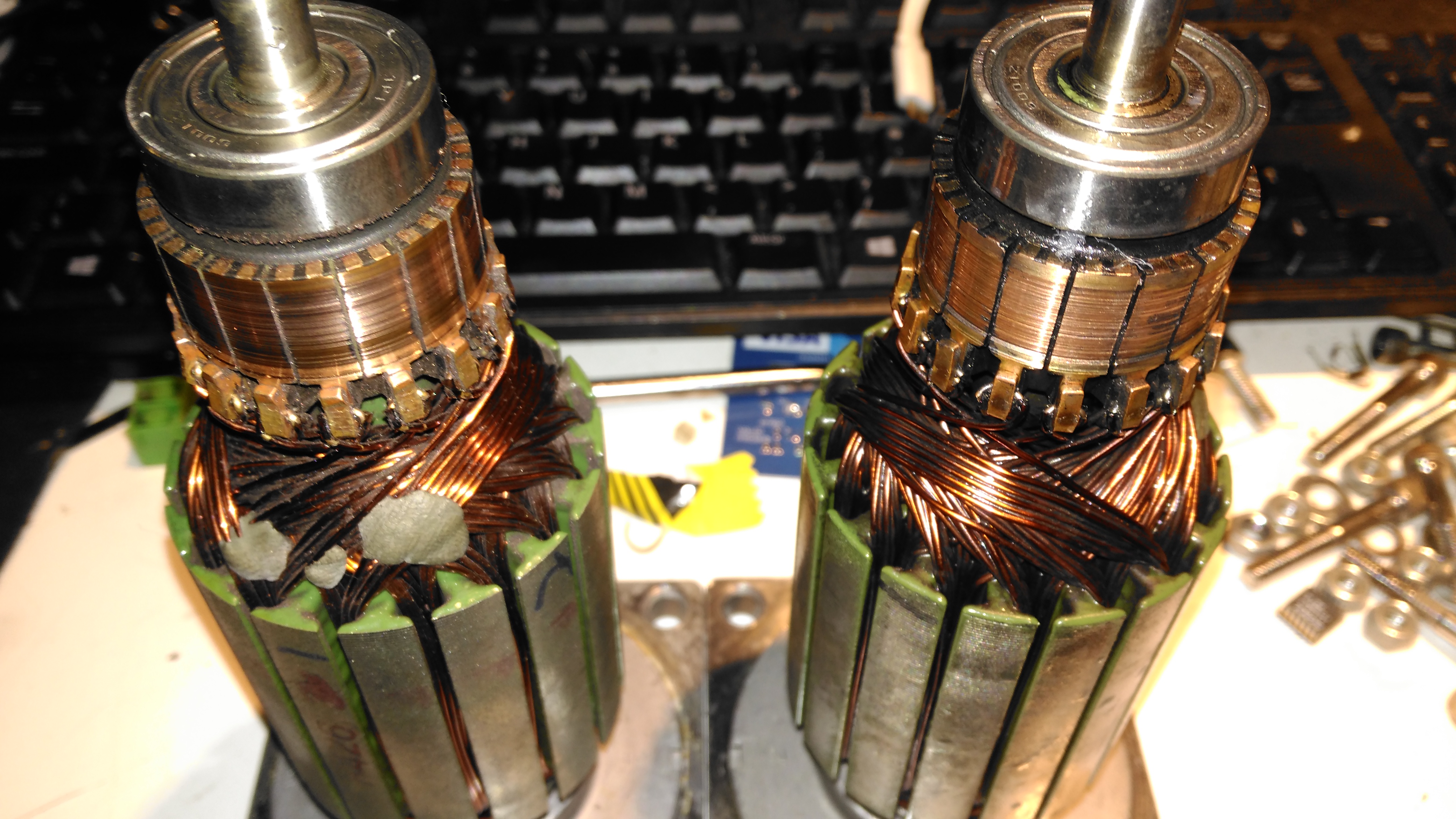
Armatures
Here’s both armatures together, with the contaminated one on the right, after some cleaning to remove most of the greasy old grok & brush dust from everything. The windings on the damaged left hand wheelchair motor haven’t darkened, which I would expect from severe overheating damage, so I’m hoping this armature is OK, and won’t require a rewind. Using an ohmmeter on these windings doesn’t tell me much – there’s only 7 turns of 0.86mm (20AWG) magnet wire in each coil, so they read as a dead short anyway. There was some leakage between the windings and the core before I cleaned things up – this was in the high (28+) megohms range, but this seems to have cleared now I’ve given things a real good cleaning.
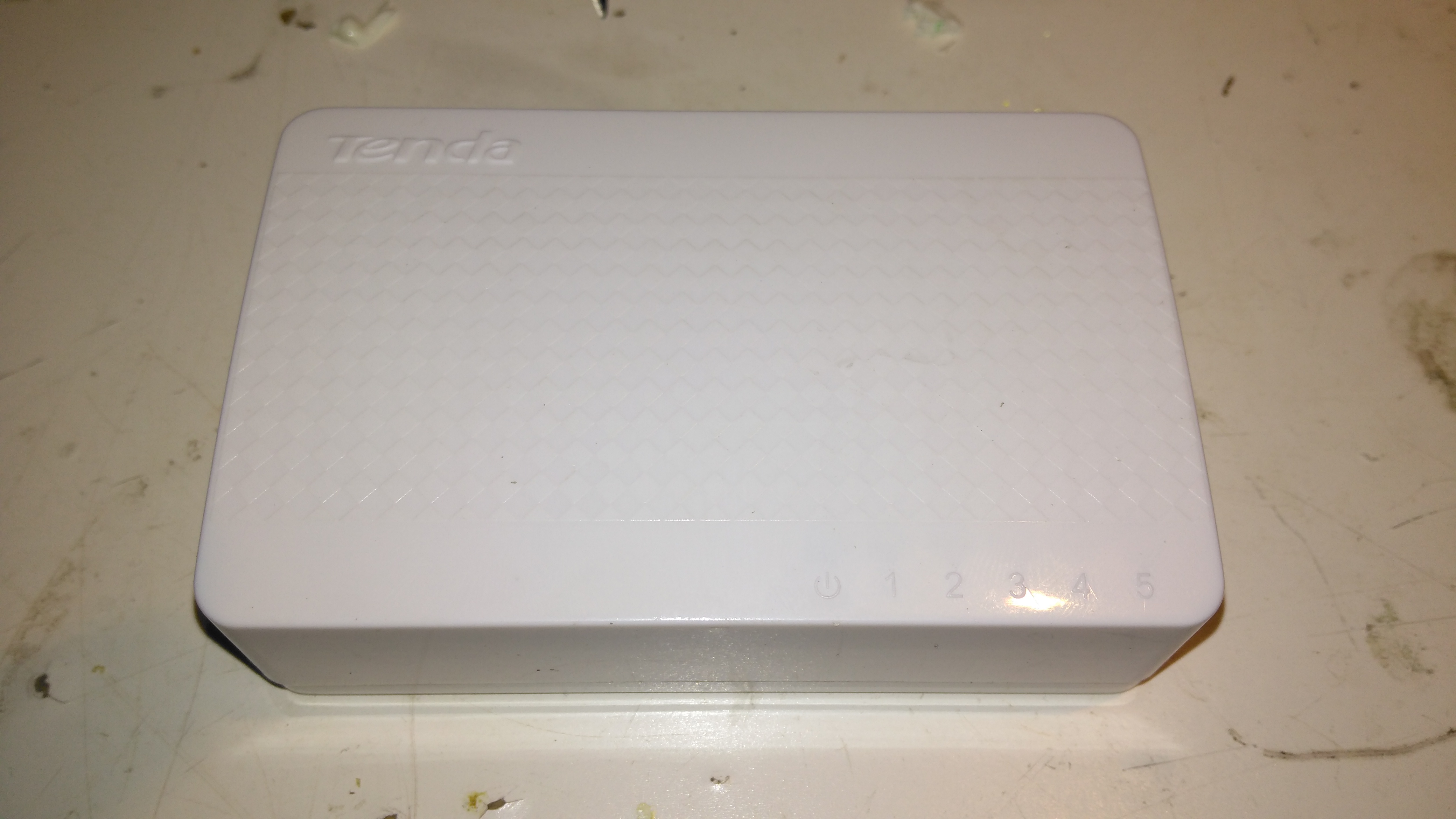
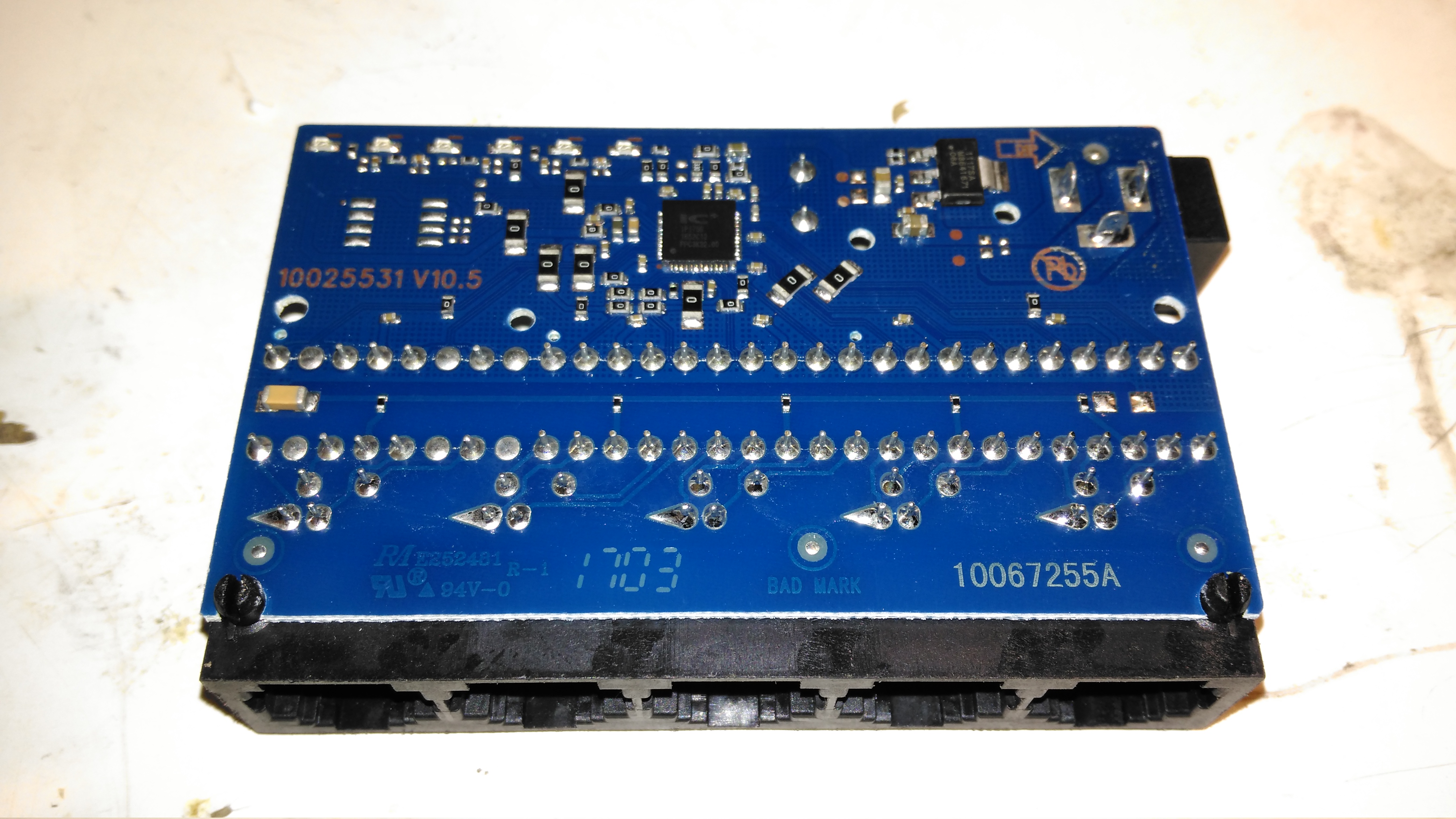
Here’s a tiny ethernet switch from the great fle market that is eBay – the Tenda S105. This unit has 5 ports, but only supports 10/100M. Still, for something so small it’s not bad.
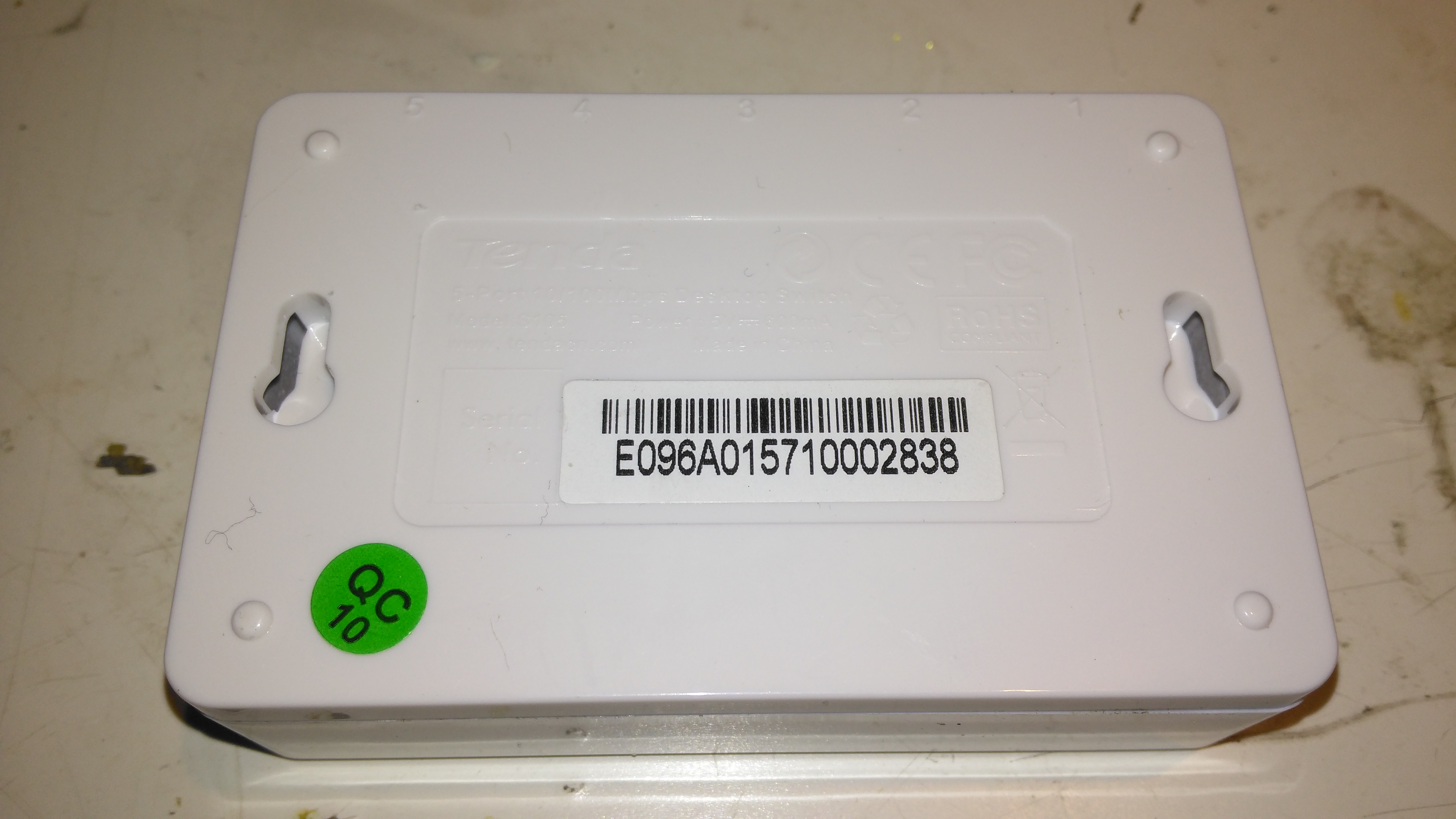
Bottom
Not much on the bottom, there’s a pair of screw hooks for mounting this to a surface.
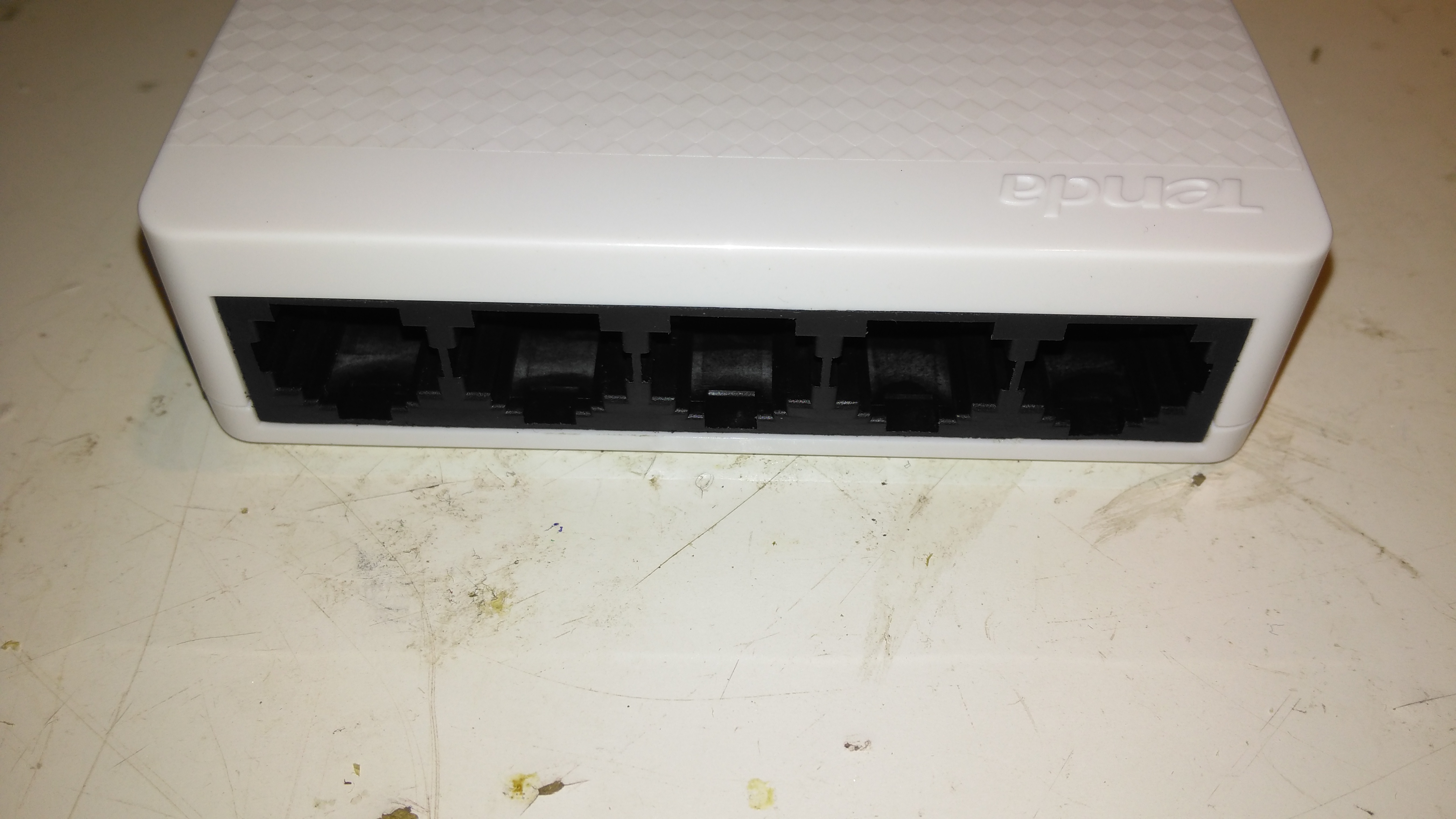
Ports
The 5 ports on the front actually have the pins for the unused pairs of the ethernet cables removed – saving every penny here.
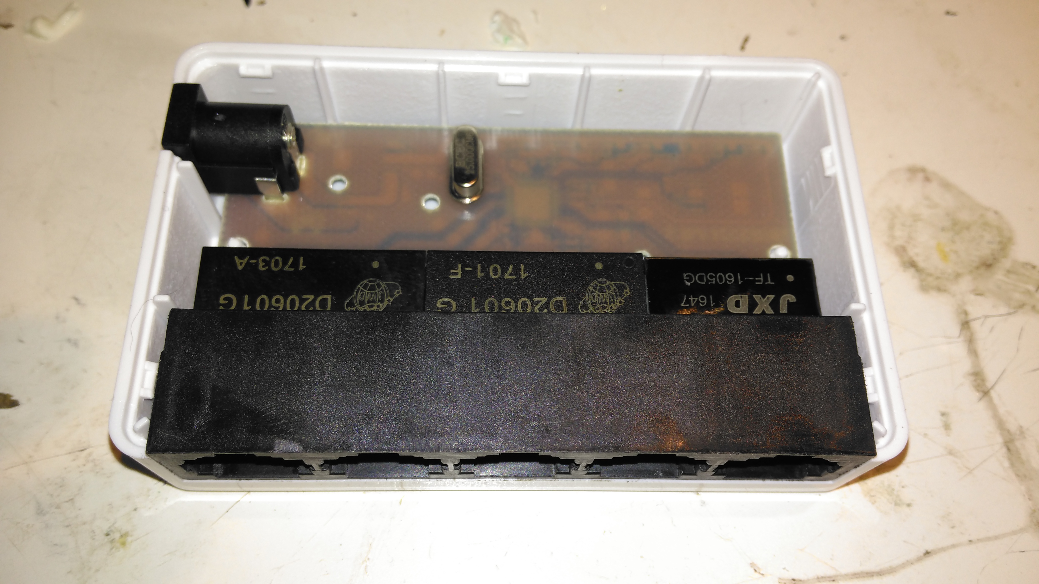
PCB Top
The casing just unclips, revealing the small PCB. Nothing much on the top, just the connectors, isolating transformers & the crystal for the switch IC.
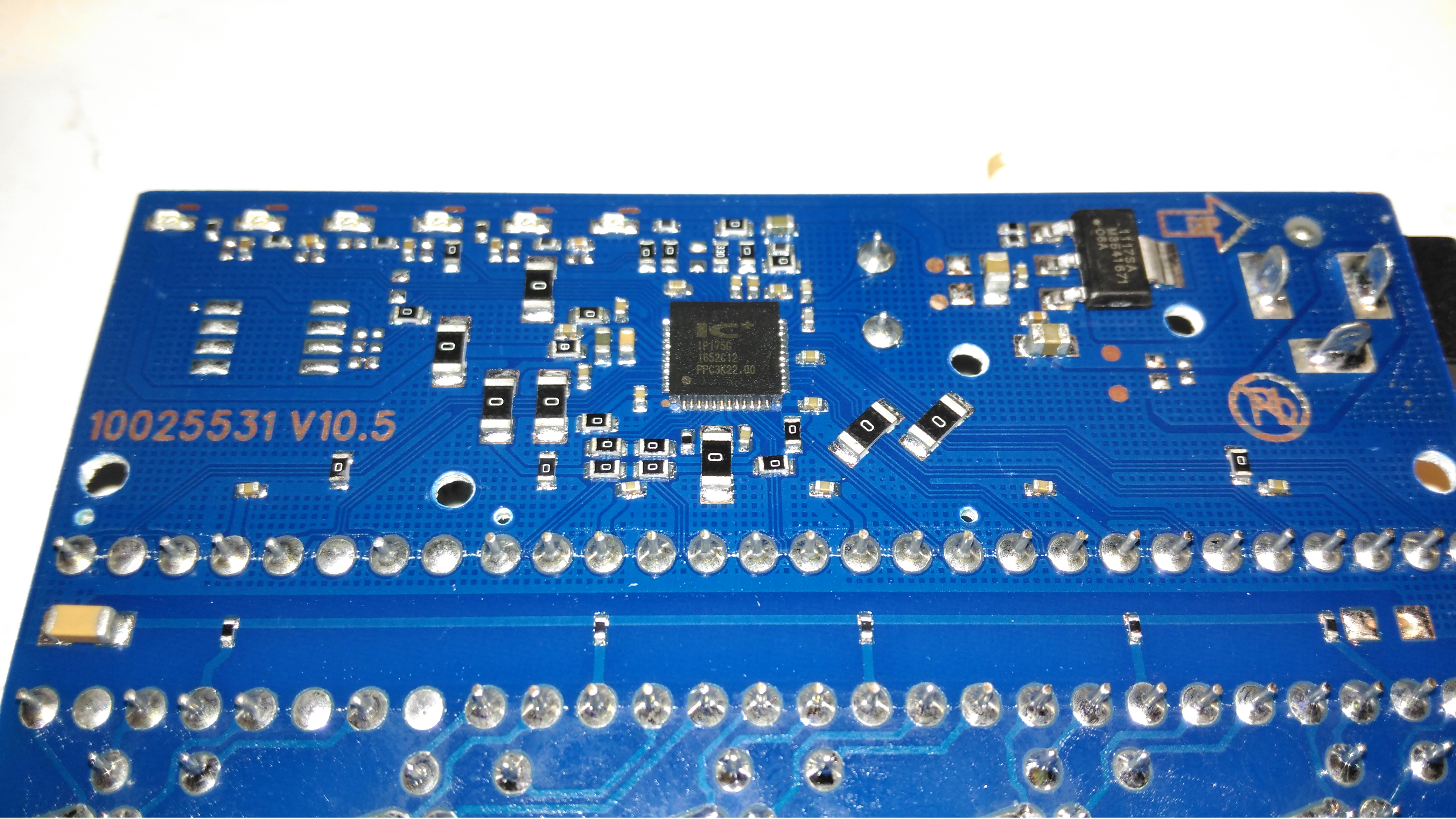
PCB Bottom
The bottom of the PCB is a little more busy, mainly with decoupling components. There’s a 3.3v linear regulator to step down the 5v input for the switch IC.
Switch IC
The IC doing all the data switching is an IP175G 5-Port 10/100 Switch from IC+ Corp. No datasheet available for this, but it’s going to be a bog-standard switch.
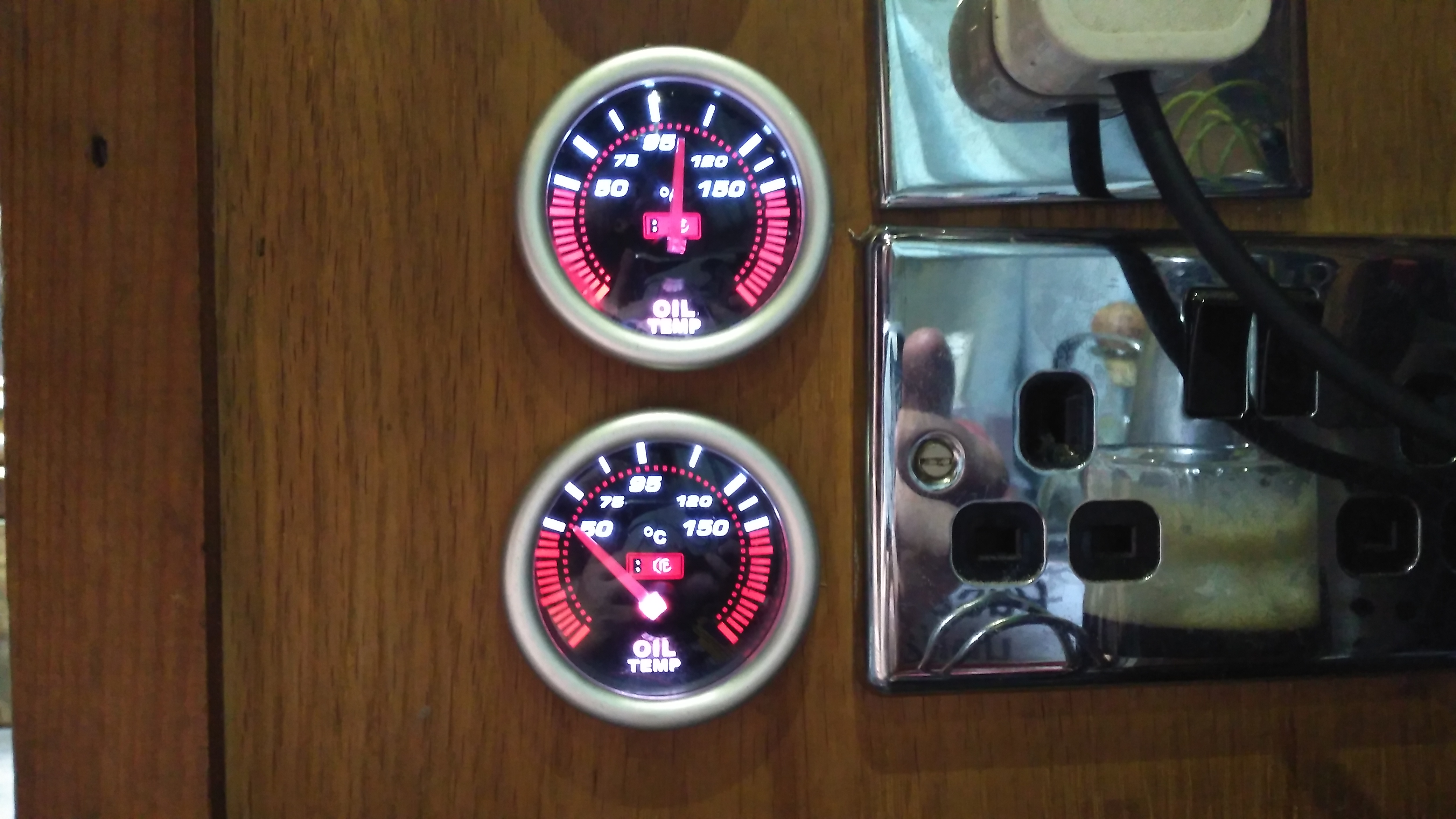
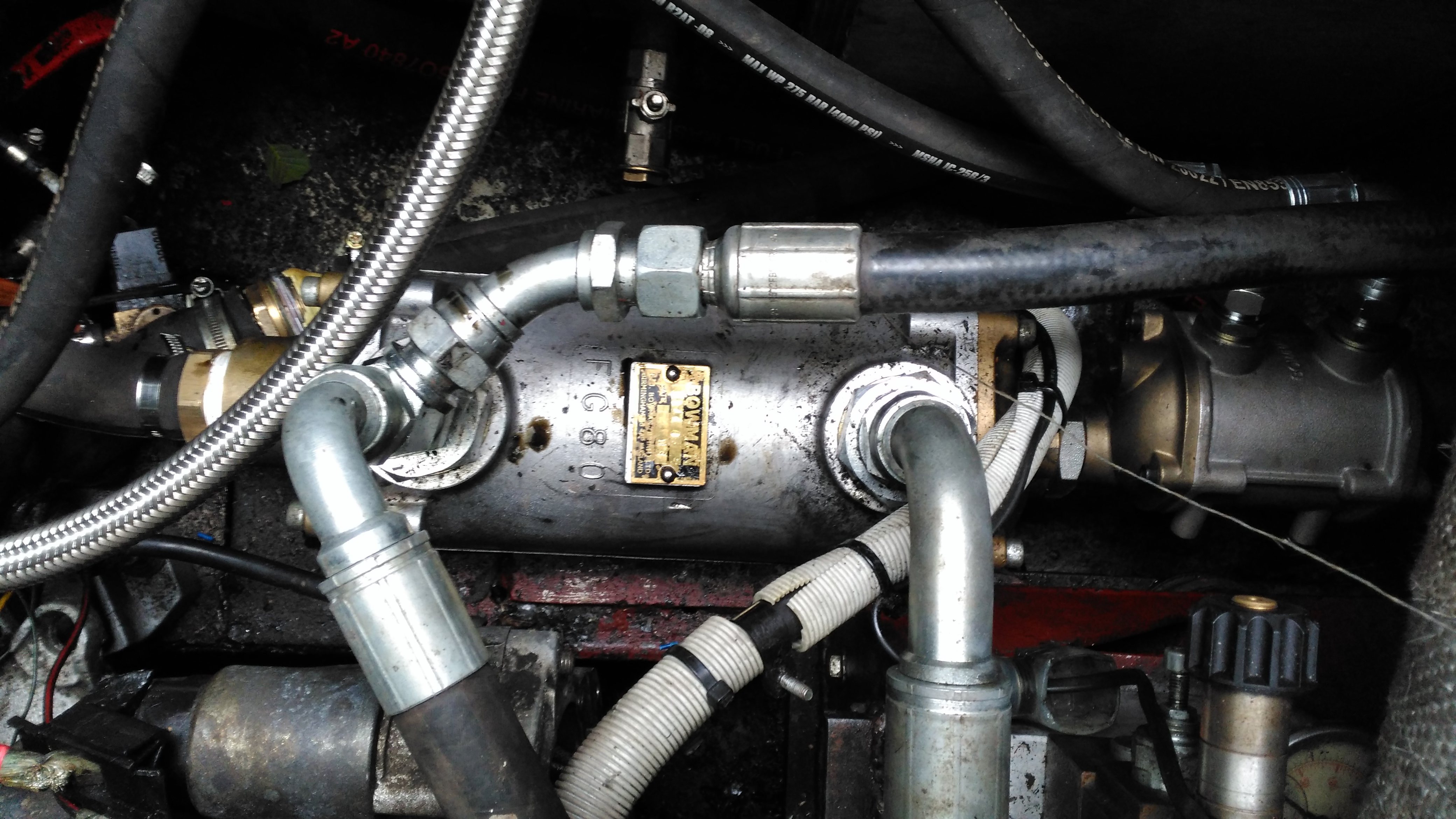
Since the engine & hydrostatic transmission were installed in the boat a few years back, the hydraulic oil cooler has been in the same fresh water circuit as the engine’s water cooling system, however this has been causing some heat issues with the engine & hydraulic system under a heavy load, such as when I’m using the onboard generator to run the welding gear. The hydraulic oil temp would rise to over 80°C during the course of a long day’s cruising – such temperatures will degrade the oil very quickly, and in turn will cause premature wear of the very expensive hydraulic pumps. (Not to mention increasing the requirement for hydraulic oil changes, which are very expensive). The engine oil has been cooled by a standard automotive oil radiator, with air forced over the matrix by two large fans. This is also pretty inefficient, so another cooler will be added to replace the automotive one.
This cooling requirement is caused by the inefficiency of hydraulic systems – a simple variable displacement piston pump driving a bent-axis piston motor has an overall efficiency of roughly 80%. Given our engine’s max power of 76HP (56.7kW), this gives an energy loss of 15.2HP (11.33kW) at maximum power. This extra heat overloaded the skin tank, resulting in a cooling system that didn’t really work all too well once the engine was hot.
To solve this issue, we’ve decided to run a raw water circuit using the canal to remove the waste heat from the hydraulic system & engine oil, putting less of a heat load on the skin tank to bring the temperatures down to something reasonable. The image above show the system at running temperature after I installed the monitoring instruments. The top gauge is measuring engine oil temperature, at the point where it’s being fed to the bearings. The bottom one is measuring hydraulic oil temperature.
The engine oil temperature does have to be higher than any other cooling circuit on board, to boil off any condensate from the cylinders. Overcooling the oil in the sump will eventually cause sludging as the oil tries to absorb the resulting water. I’m aiming for a system temperature in the engine oil circuit of 95°C-120°C when the engine is under load & at operating temperature.
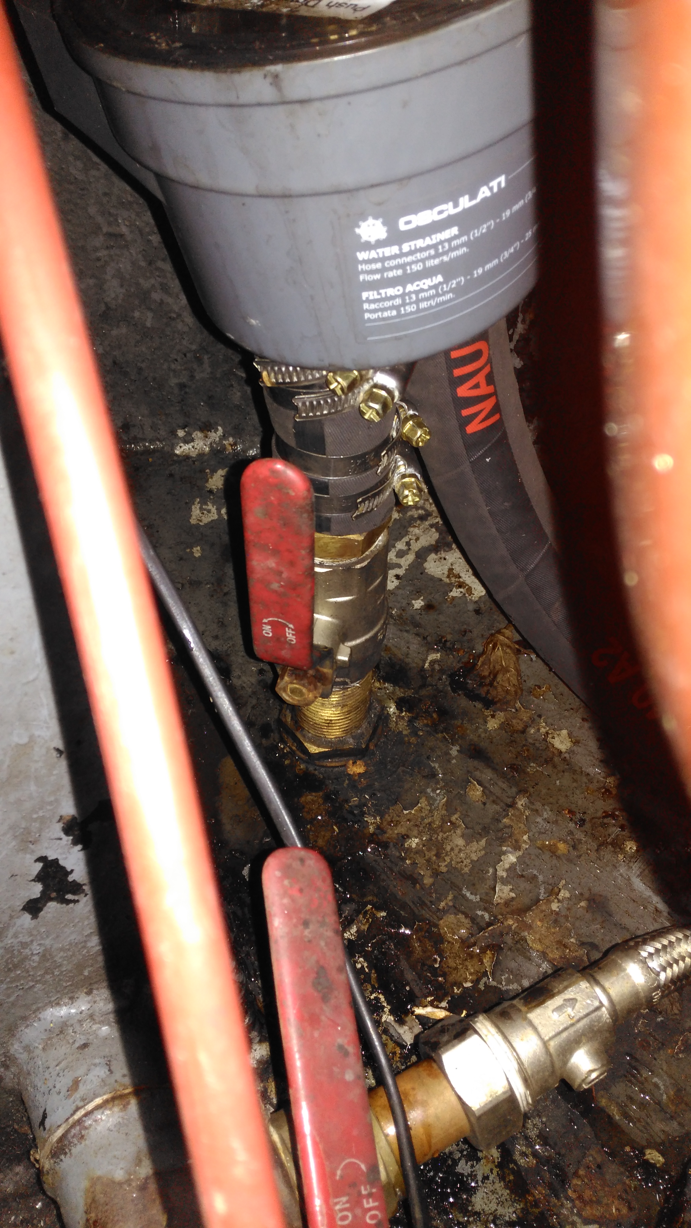
Raw Water Suction
Water from the canal is drawn from a skin fitting installed at the last drydock visit, pulling water through a strainer to remove all the large bits of muck. The large slotted screen on the suction skin fitting keeps larger objects out of the intake.
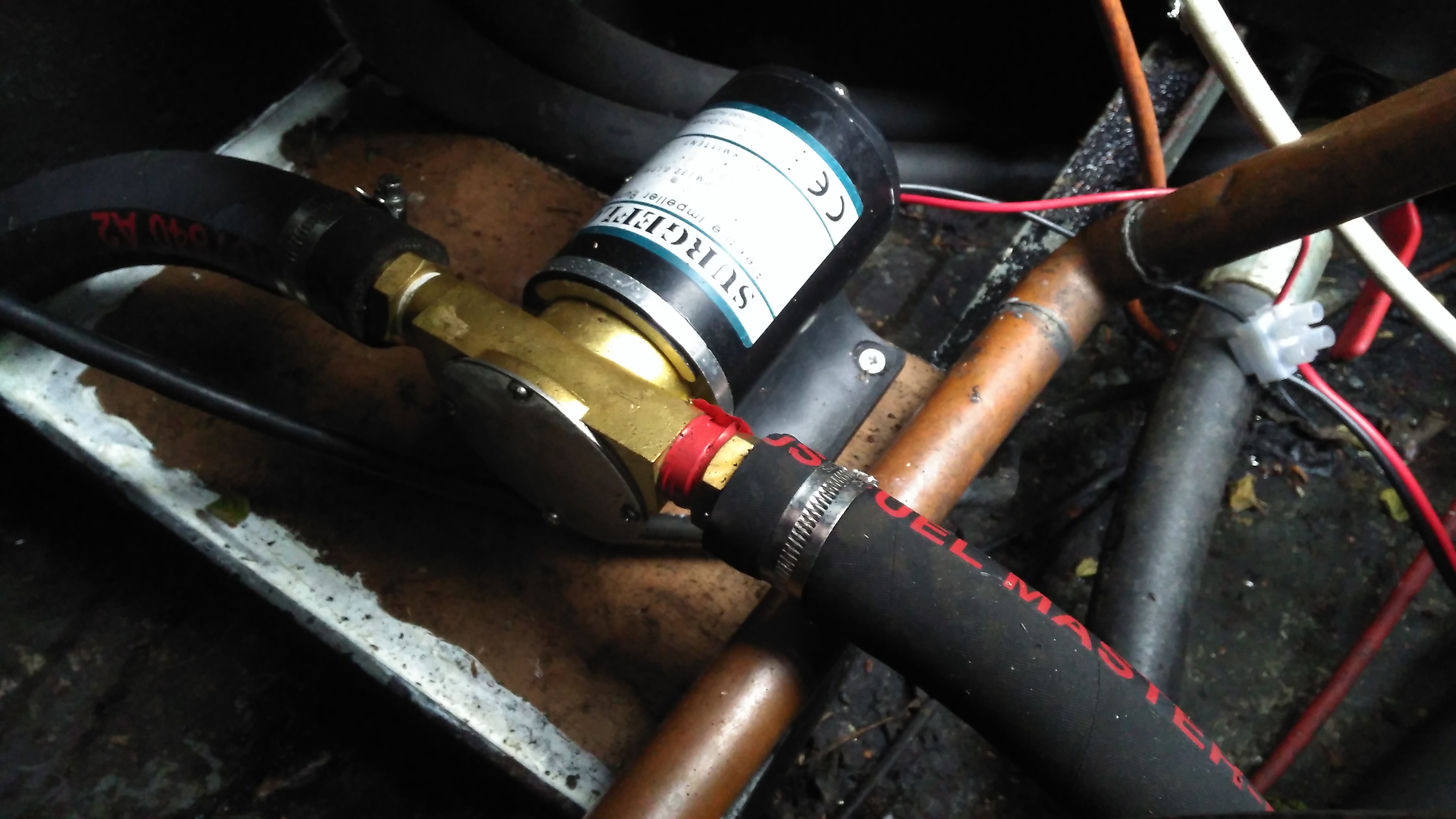
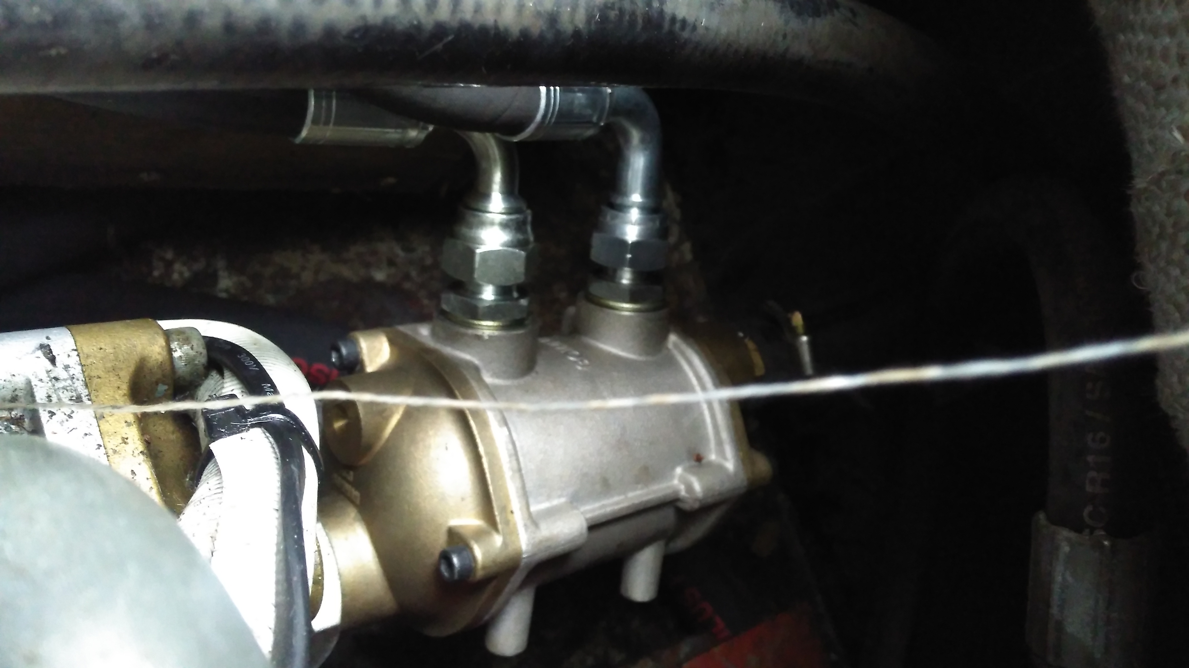
Raw Water Pump
A flexible impeller pump provides the power to move water through the system, in this case about 25L/Min. This pump is a cheap copy of a Jabsco pump from eBay. So far it’s been pretty reliable.
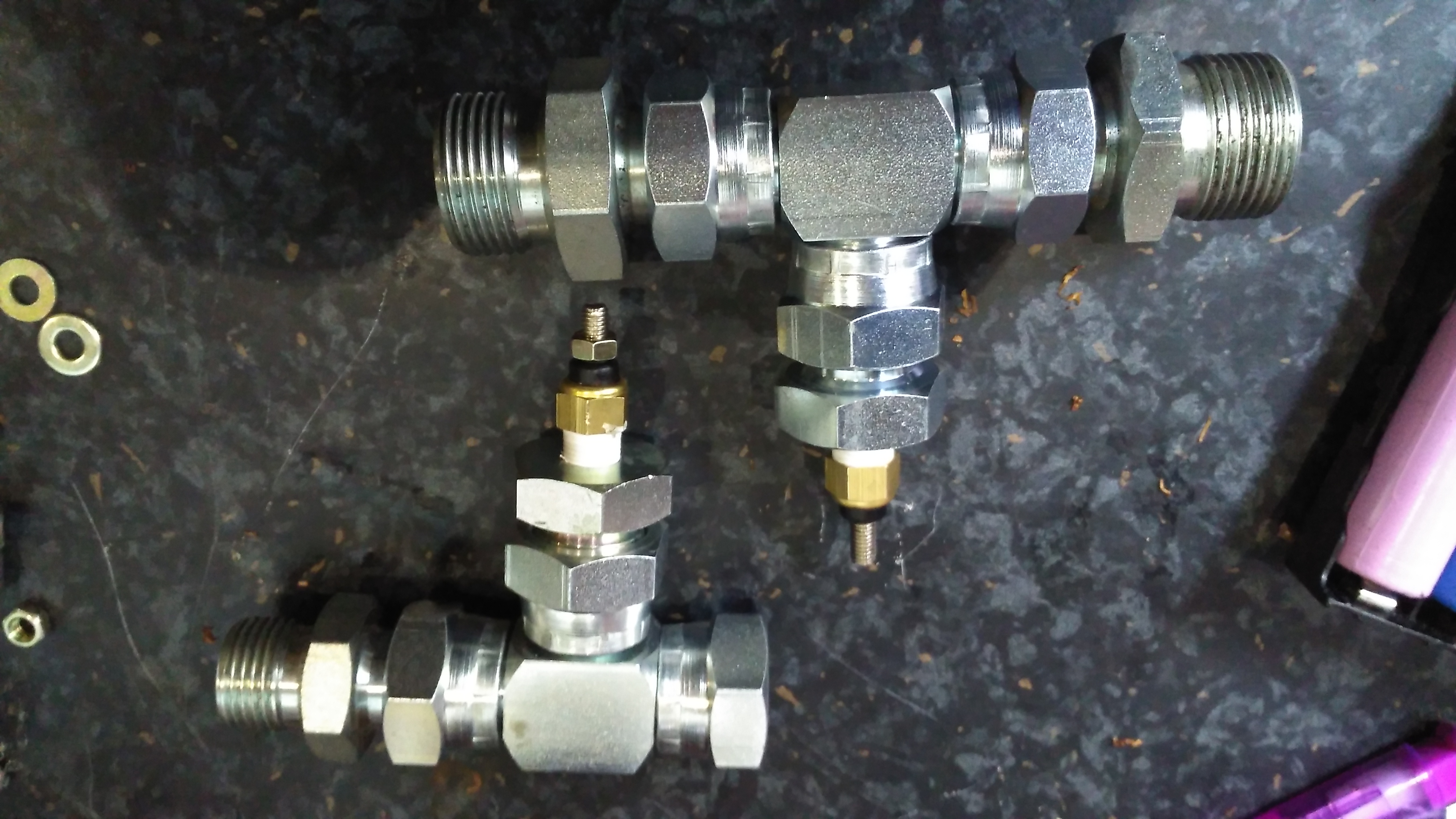
Temperature Senders
The temperature senders are standard automotive parts, and some adaptors were required to graft them into the oil lines of both systems. The senser’s 1/8″ NPT threads are here fitted into 1/2″ BSP hydraulic fittings.
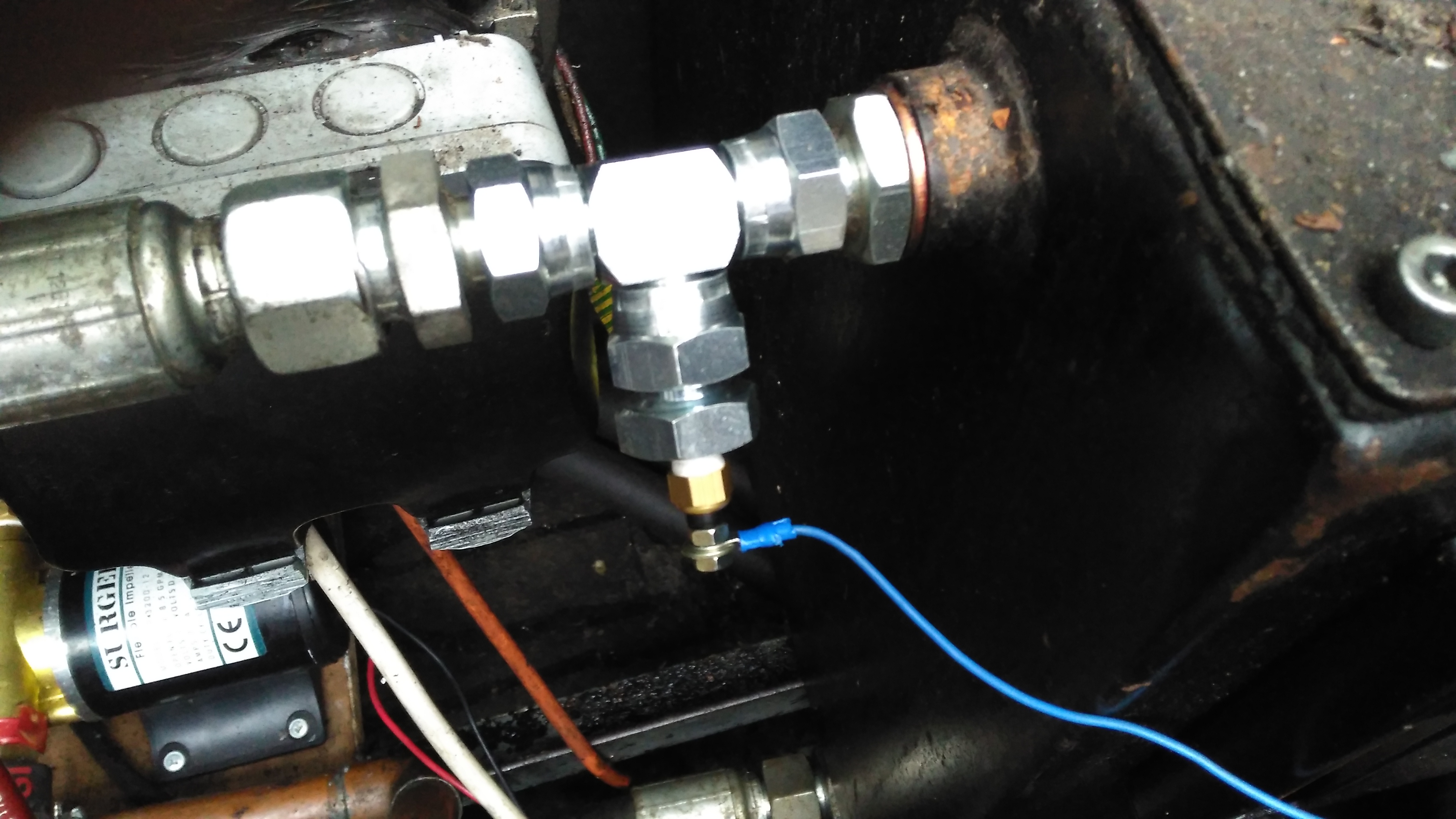
Hydraulic Temperature Sender
Here’s the hydraulic oil sender installed in the drain line from the main propulsion pump, this should give me a pretty good idea of the temperature of the components in the system, the sender is earthed through the steel hydraulic oil tank.
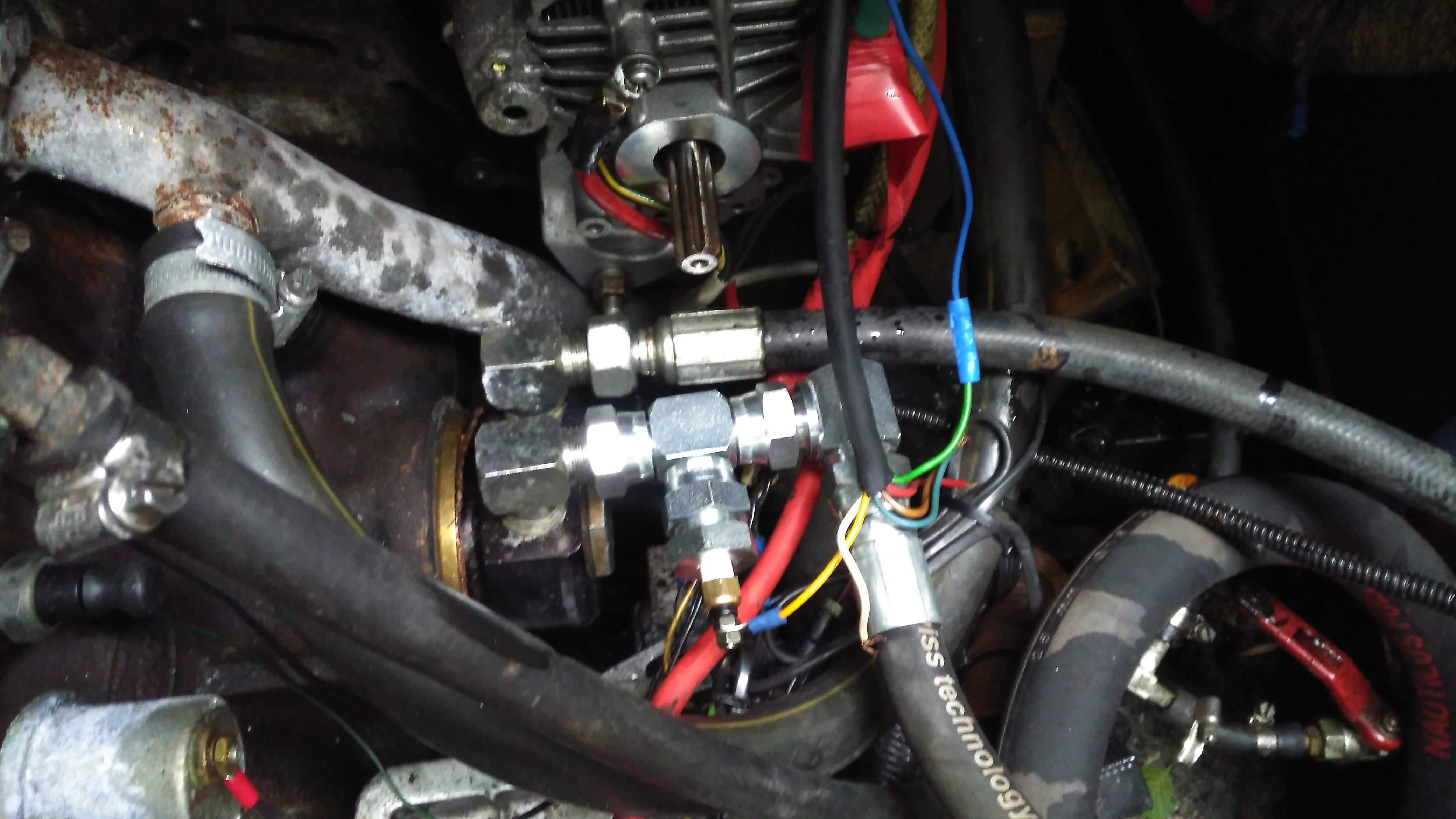
Engine Oil Temperature Sender
The oil temperature sender is installed in the return line to the engine from the heat exchanger. This is measuring the oil temperature the bearings in the engine are being fed with.
Hydraulic Oil Heat Exchanger
The stack of heat exchangers is located on the starboard side of the engine bay, the large one here is cooling the hydraulic oil, the auxiliary pump is continually circulating the oil from the tank through this, then into the return filter on the top of the tank.
Engine Oil Heat Exchanger
The engine oil is fed through this much smaller heat exchanger mounted on the back of the large hydraulic cooler, the last in the circuit before the water is discharged back overboard through a skin fitting.
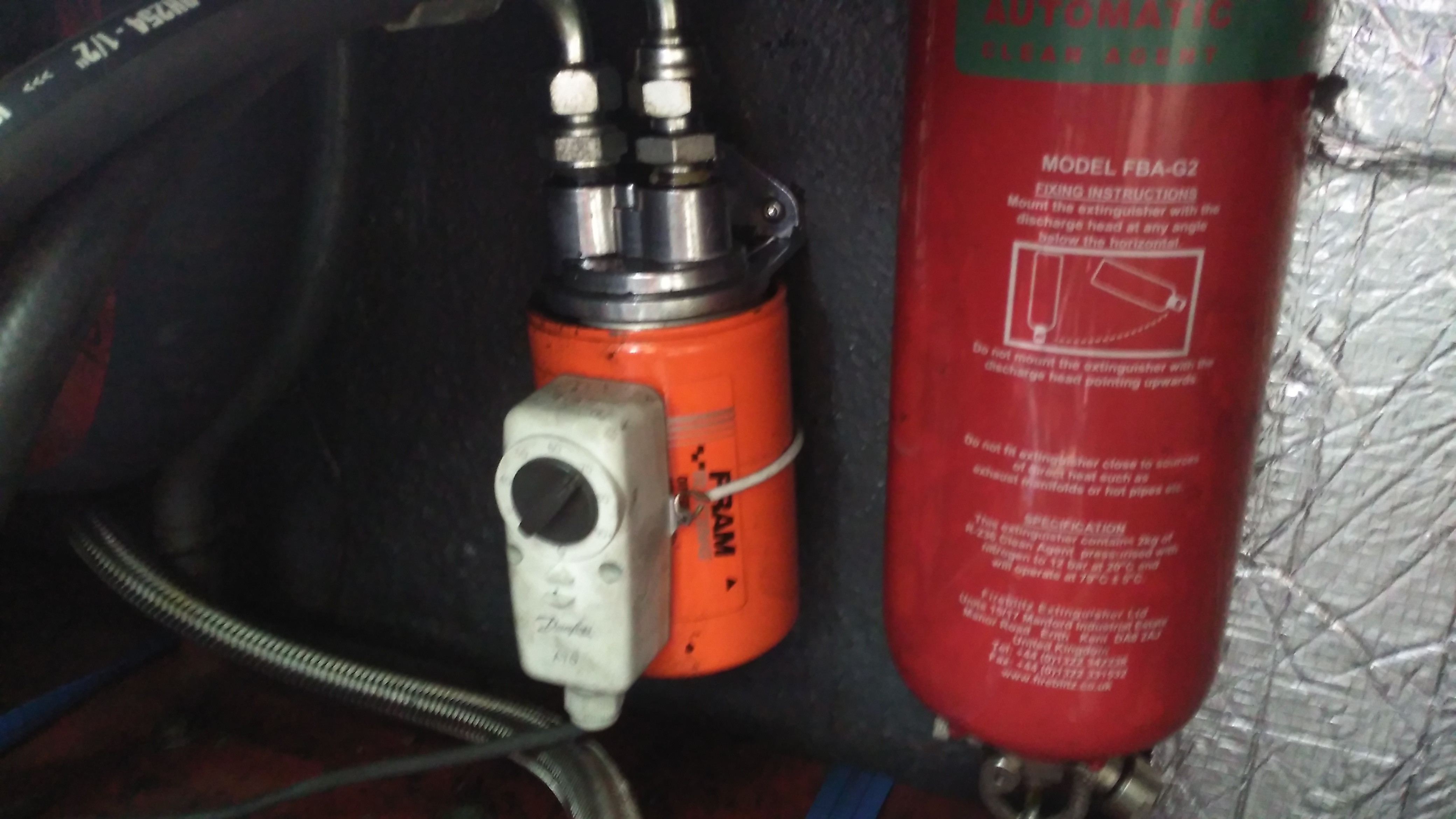
Remote Oil Filter
As we’ve got the diverter block on the side of the engine where the oil filter should be, a remote oil filter is fitted above the fuel tank. The thermostat strapped on operates the main engine bay ventilation fans, switching them on once the engine oil reaches 60°C.
Since I’ve been working on the backend servers a lot over the past few days, I’ve decided it was time to get some broken things on the blog fixed.
Firstly, the radiation monitor graphs. Originally I was using a Raspberry Pi to grab the data from the local monitor, and that was connecting via FTP to the server over in the datacentre to push it’s graph images. Since the server is now on the same local network as the monitor, there’s no need to faff about with FTP servers, so I’ve rejigged things with some perl scripts from cristianst85 over on GitHub, running on the web server itself.
I deviated from the suggested place to put the scripts on the server & opted to store everything within the Experimental Engineering hosting space, so it gets backed up at the same time as everything else on a nightly basis.
The maximum number of views of this element is reached. Please contact the webmaster to enable unlimited views.
This is also accessible from the menu at top left, the script pulls data from the monitor & updates the images every 60 seconds via a cron job.
I’ve removed a couple of dead pages from the blog system, along with some backend tidying of the filesystem. Over the years things have gotten quite messy behind the scenes. This blog is actually getting quite large on disk, I’ve hit the 15GB mark, not including the database!
Caching is enabled for all posts on the blog now, this should help speed things up for repeat visitors, but as most of my content is (large) image based, this might be of limited help. I’m currently tuning the MySQL server for the load conditions, but this takes time, as every time I change some configuration settings I have to watch how things go for a few days, before tweaking some more.
Server Control Panels – More Of The Same
Sorry Sentora. I tried, and failed to convert over to using it as my new server control panel. Unfortunately it just doesn’t give me the same level of control over my systems, so I’ll be sticking with Virtualmin for the foreseeable future. Sentora stores everything in, (to me at least), very odd places under /var/ and gave me some odd results with “www.” versions of websites – some www. hosts would work fine, others wouldn’t at all & just redirect to the Sentora login interface instead. This wasn’t consistient between hosting accounts either, and since I didn’t have much time to get the migration underway, this problem was the main nail in the coffin.
Just storing everything under the sun in /var/ makes life a bit more awkward with the base CentOS install, as it allocates very little space to / by default, (no separate /var partition in default CentOS), giving most of the disk space to /home. Virtualmin on the other hand, stores website public files & Maildirs under /home, saving /var for MySQL databases & misc stuff.
The backup system provided is also utterly useless, there’s no restore function at all, and just piles everything in the account into a single archive. By comparison, Virtualmin has a very comprehensive backup system built in, that supports total automation of the process, along with full automatic restore functionality for when it’s needed.
Sentora did have some good points though:
It handled E-Mail logins & mail filters much more gracefully than Virtualmin does, and comes with Roundcube already built into the interface ready to use. With Virtualmin the options are to use the Usermin side of the system for E-Mail, which I find utterly awful to use, or install a webmail client under one of the hosted domains (my personal choice).
Mail filtering is taken care of with Sieve under Sentora, while Procmail does the job under Virtualmin.
Sentora does have a nicer, simpler, more friendly interface, but it hides most of the low-level system stuff away, while under Virtualmin *everything* on the system is accessible, and it provides control interfaces for all the common server daemons.
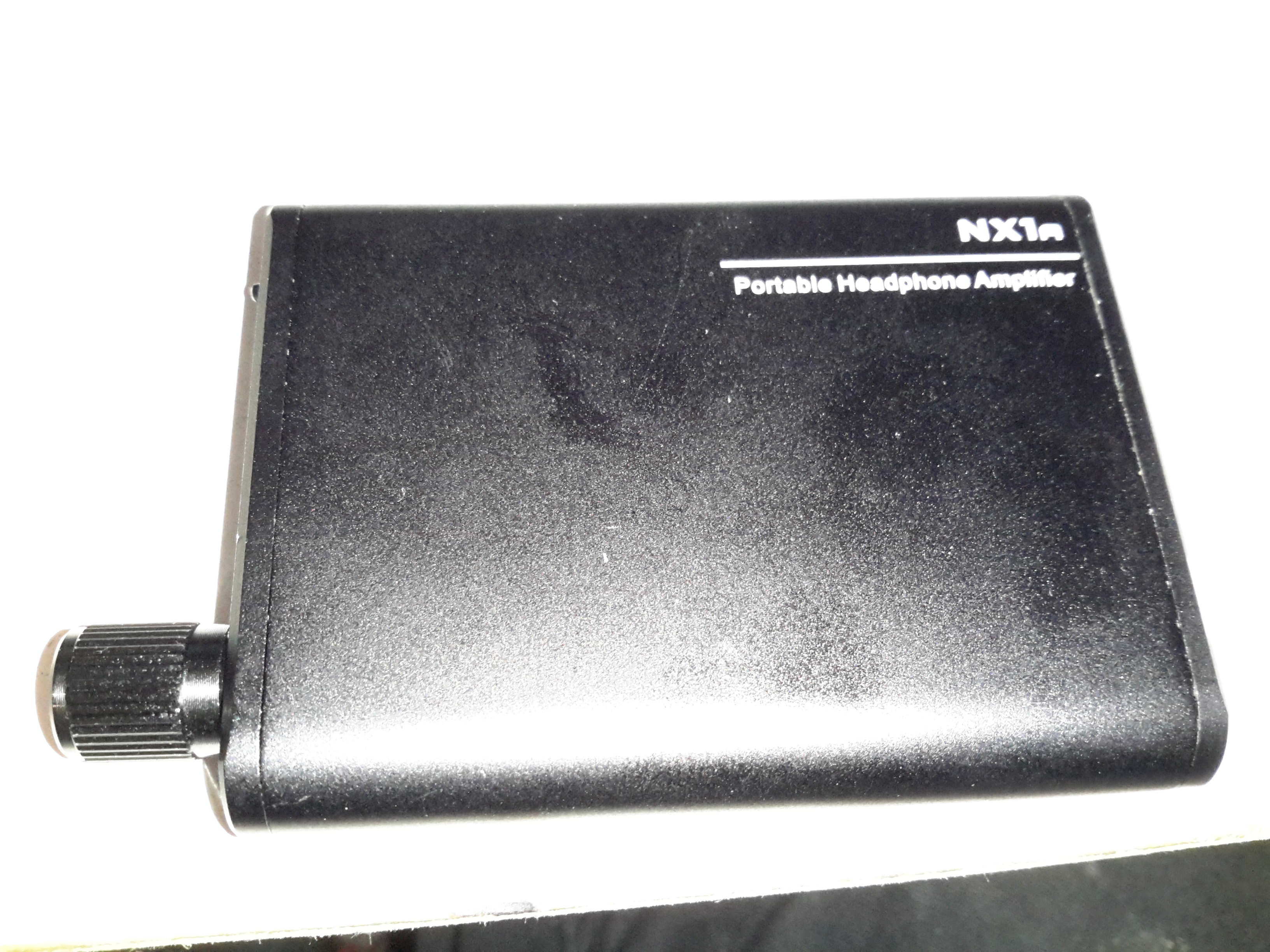
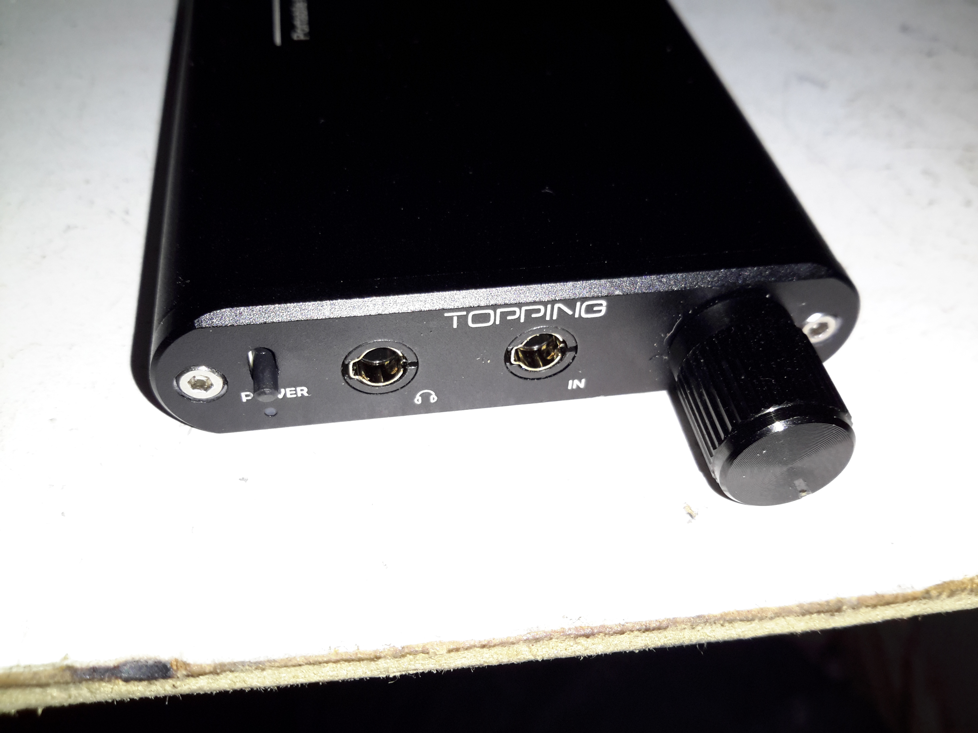
Time for another teardown! Here’s a pocket-sized headphone amplifier for use with mobile devices. This unit is powered by a built-in lithium cell, and can give some pretty impressive volume levels given it’s small size.
Audio Connections
The 3.5mm audio input & output jacks are on the front of the unit, along with the relatively enormous volume knob & power switch. There’s a little blue LED under the switch that lets the user know when the power is on, but this is a very sedate LED, using very little power.
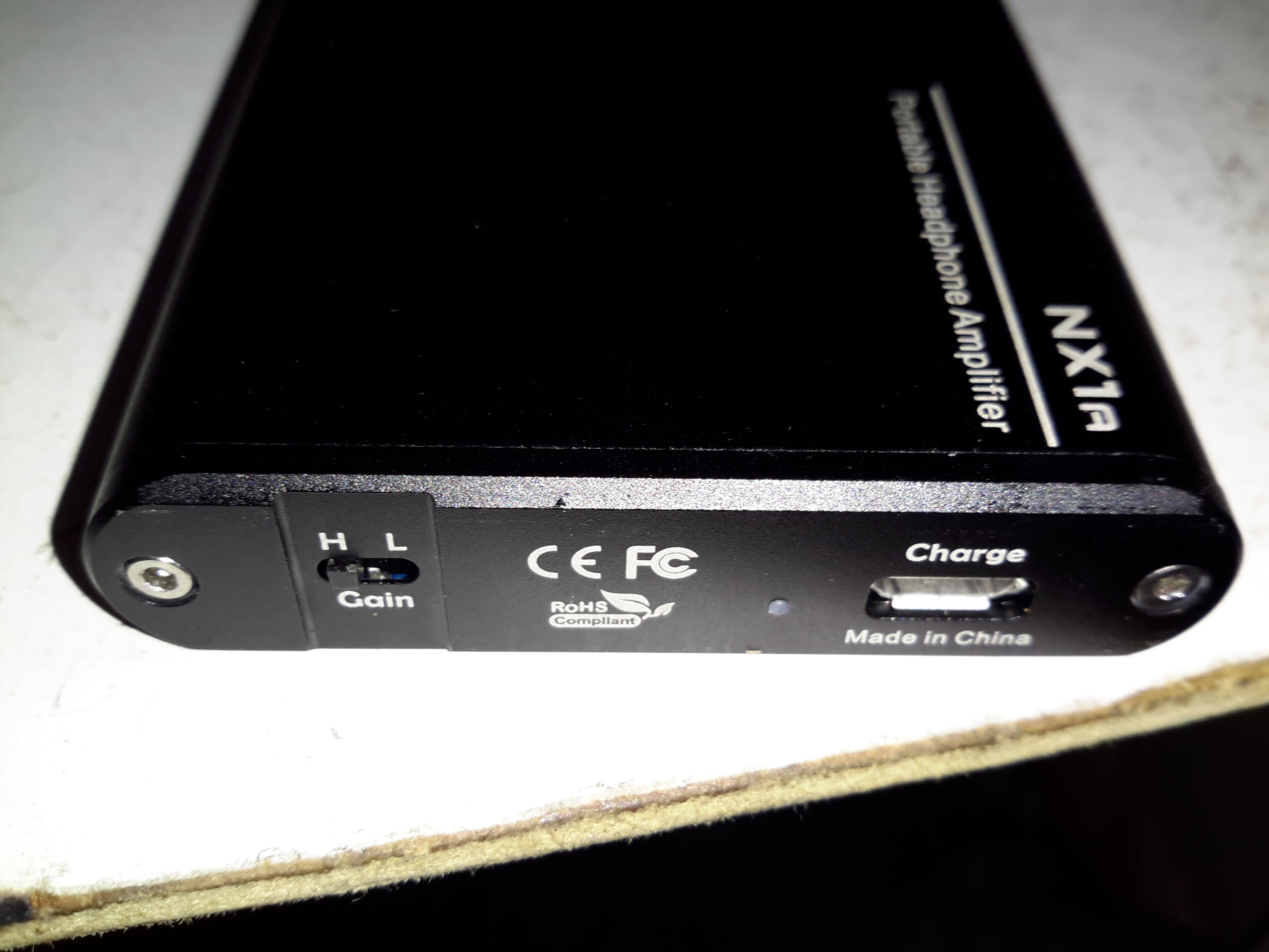
Gain & Charging
On the back is the High-Low gain switch, and the µUSB charging port. There’s another indicator LED to show that the internal cell is charging, in this case a red one.
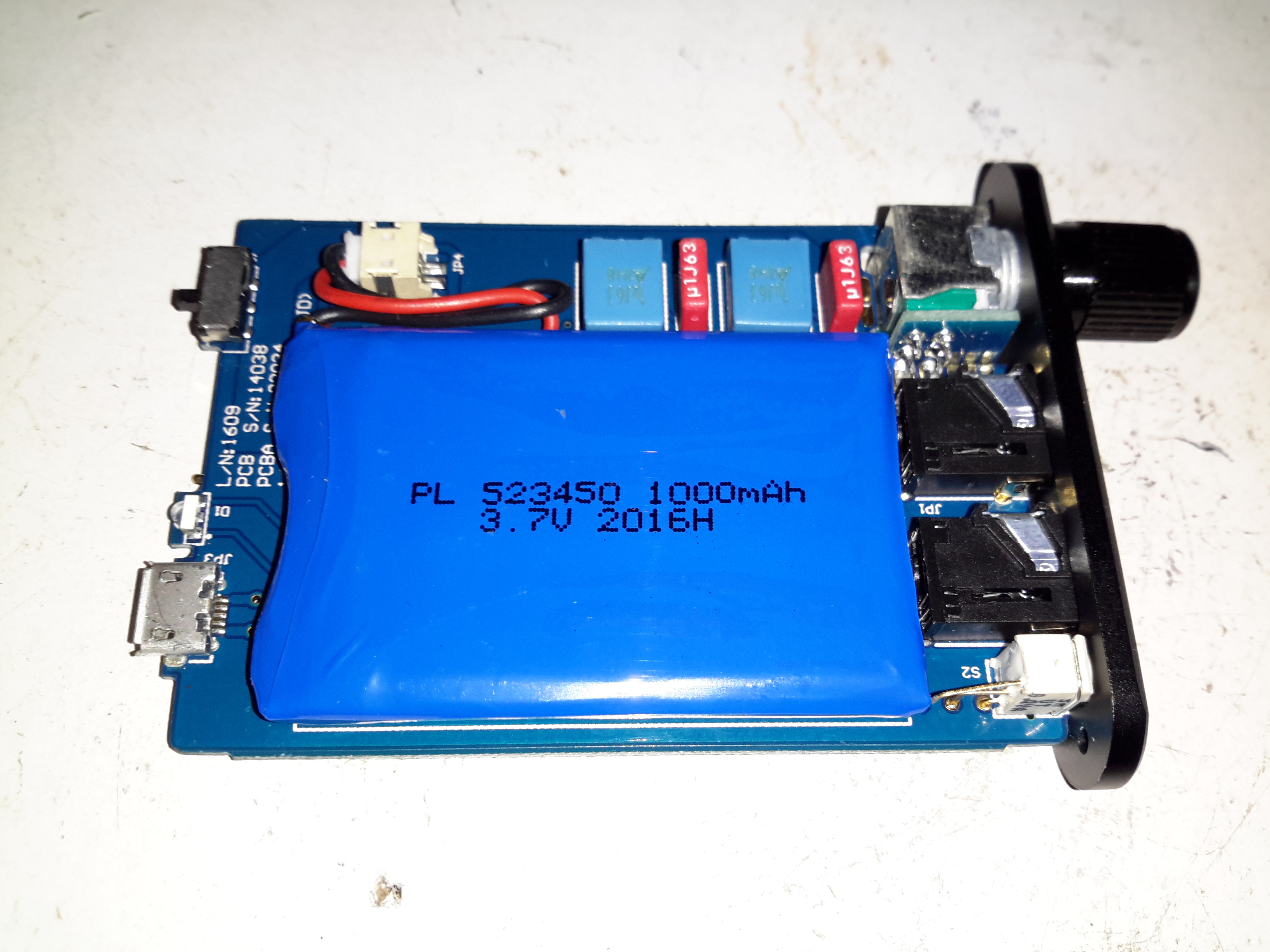
PCB Top
Removing a couple of cap screws allows the internals to slide out of the extruded aluminium casing. Most of the internal space is taken up by the 1Ah lithium cell, here on the top of the PCB secured by some double-sided tape. The volume potentiometer is mounted on a small daughterboard at right angles to get it to fit into the small vertical space in the case.
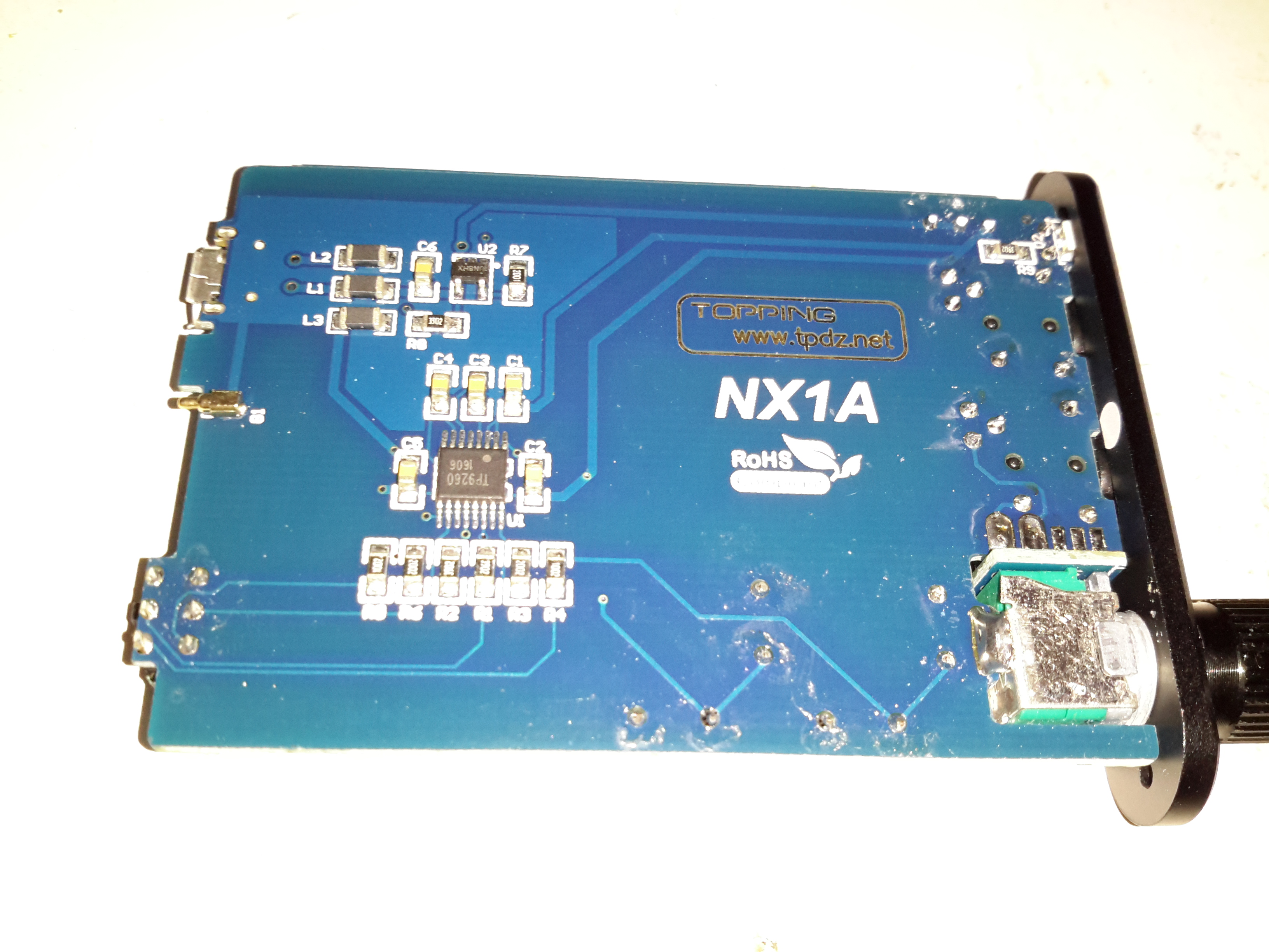
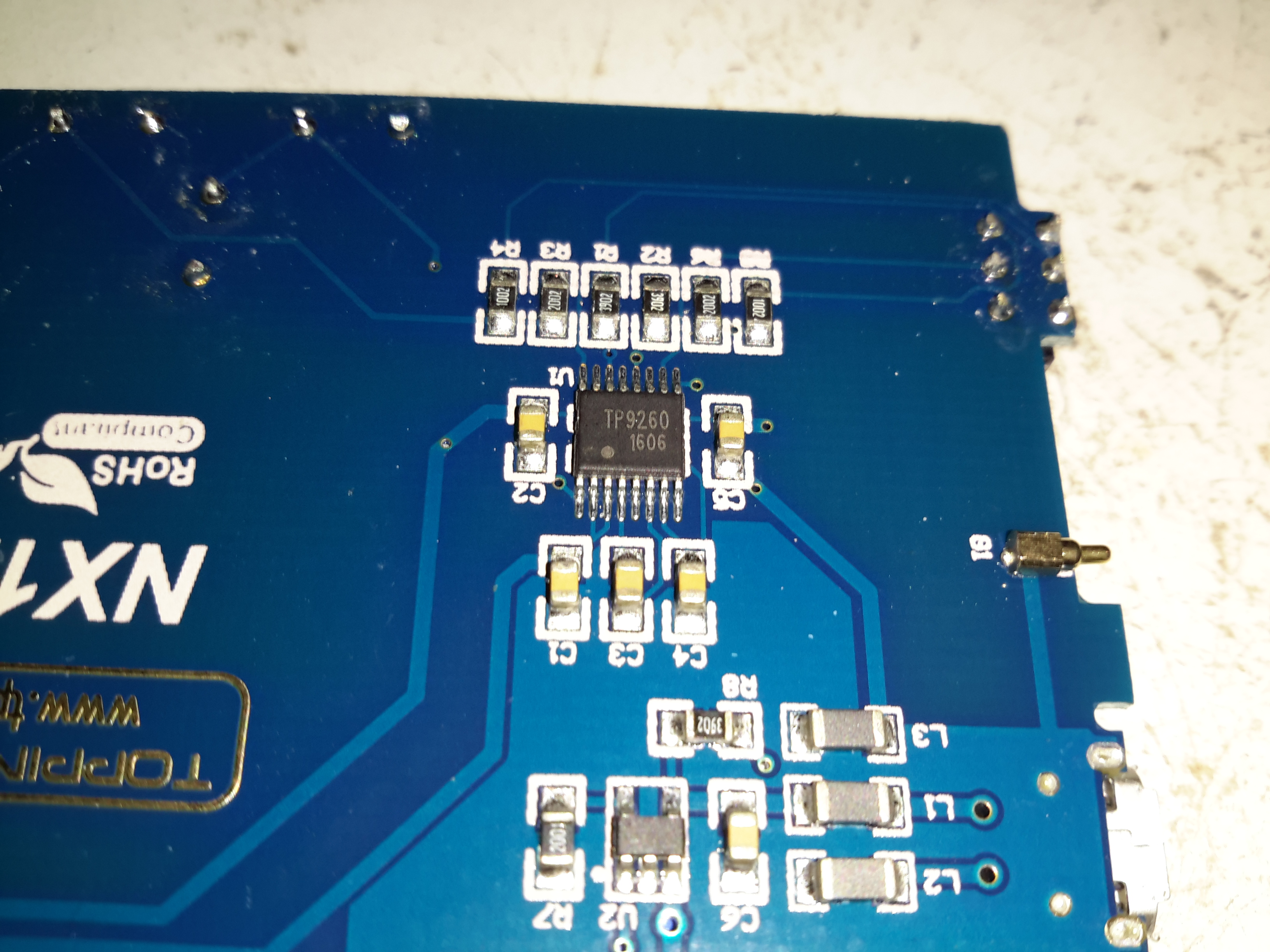
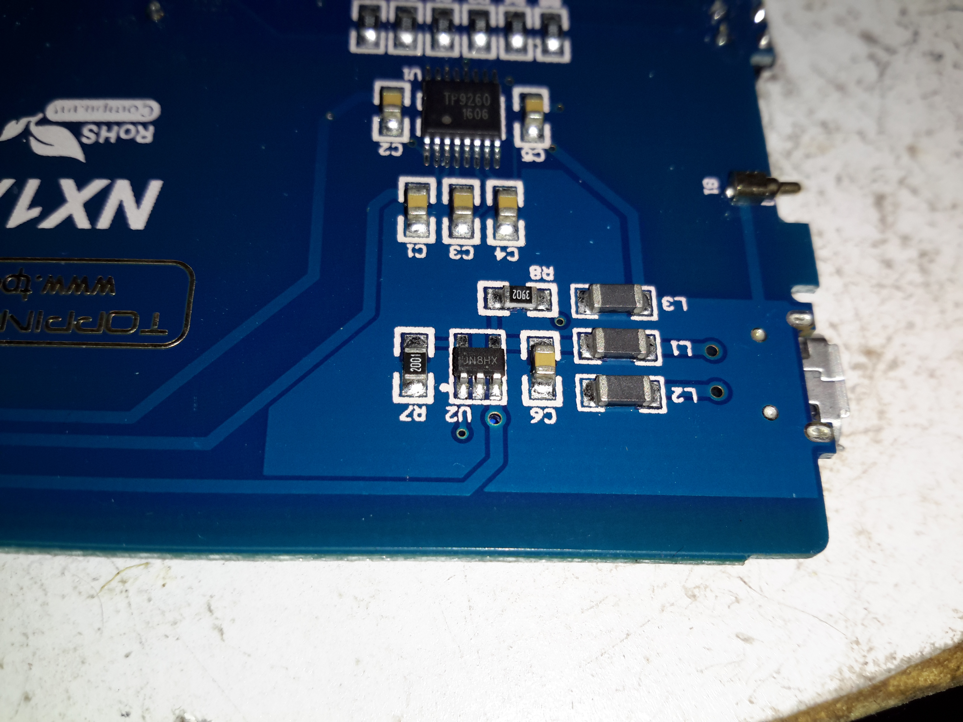
PCB Rear
The bottom of the PCB is equally as sparse – the only ICs being the main audio amp in the centre & the battery charger IC at the top.
Amplifier IC
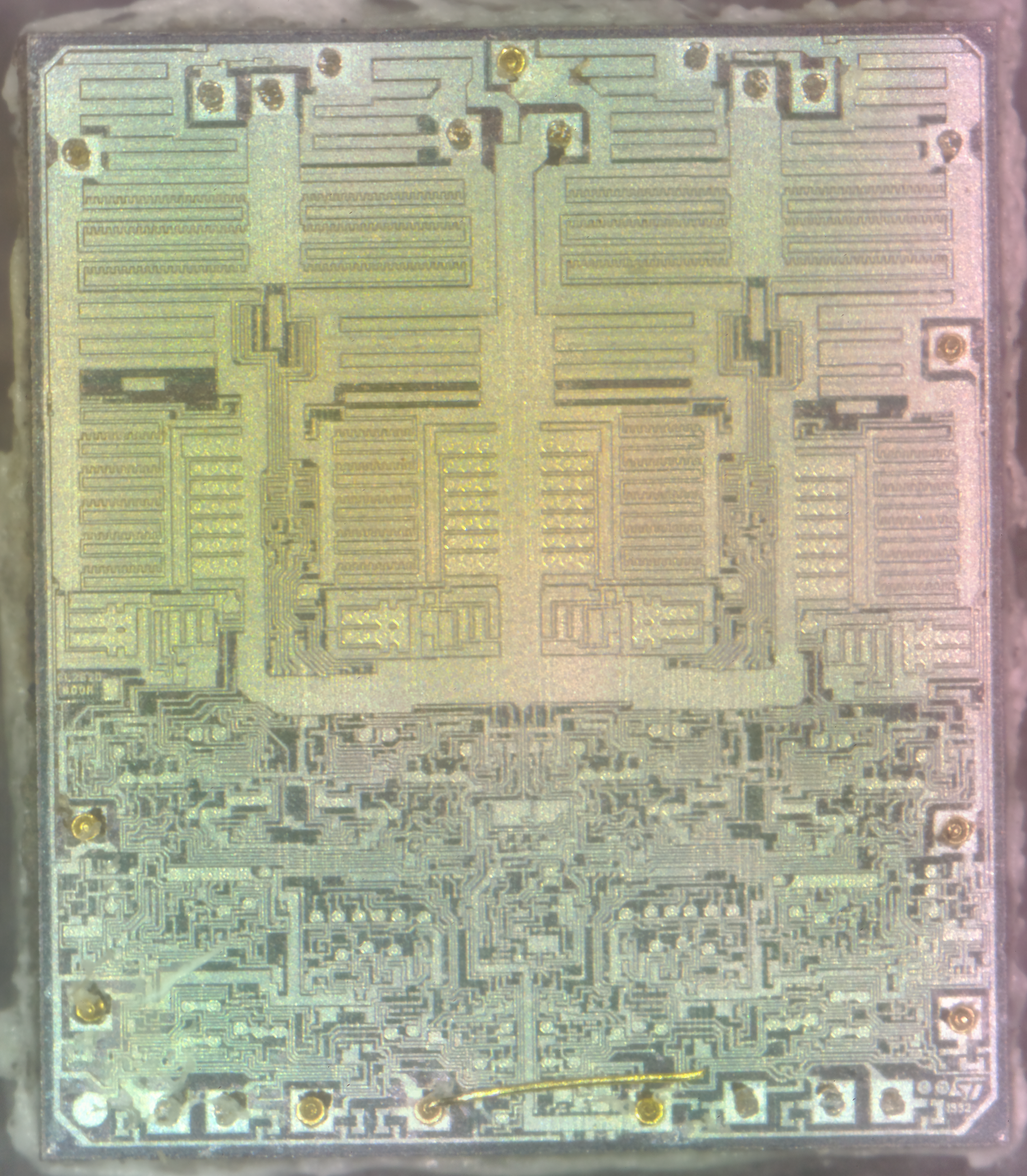
The main audio amplifier is a TP9260, I couldn’t find a datasheet on this, so I’m unsure of what the specs are. The row of resistors above the IC are for the gain divider circuit. There’s also a pogo pin on the right that makes contact with the back panel of the case for grounding.
Battery Charger
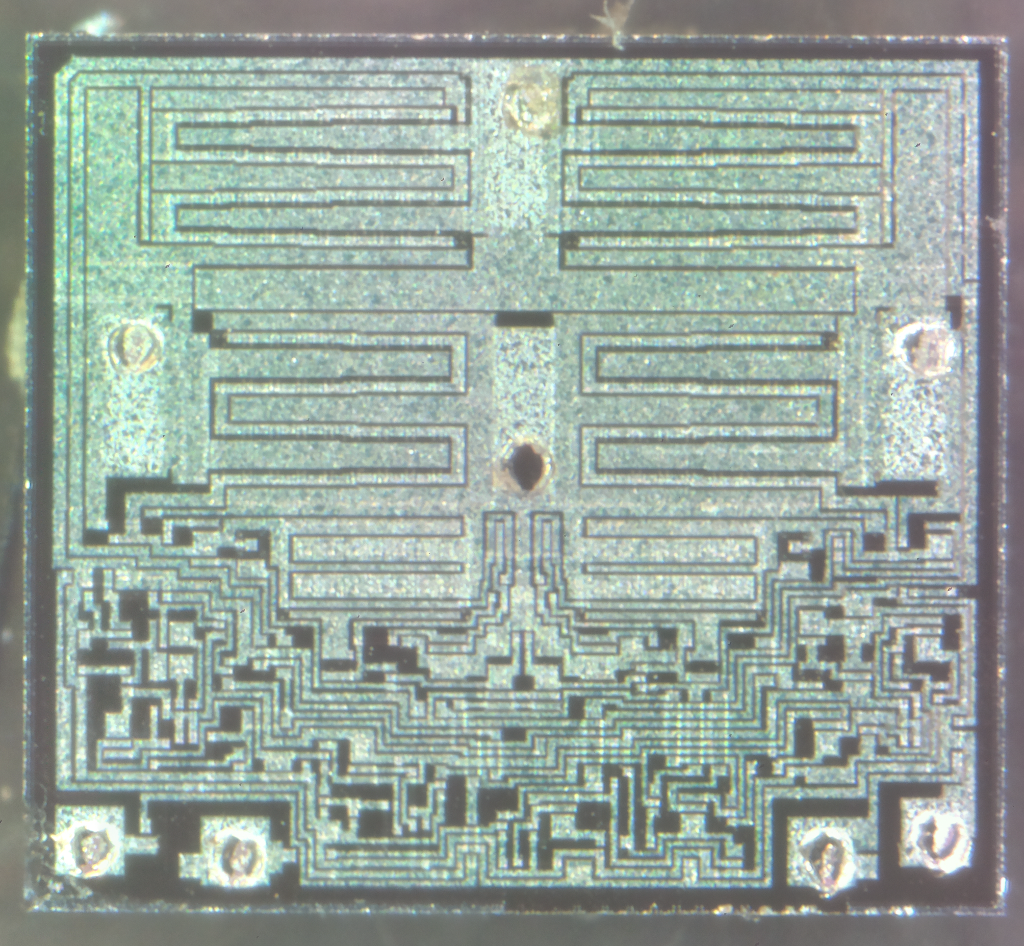
Battery charging is taken care of by a UN8HX 500mA linear charging IC, not much special here.
This little amplifier seems to be pretty well made, considering the price point. The only issue I’ve had so far is the audio cables act like antennas, and when in close proximity to a phone some signal gets picked up & blasted into the headphones as interference.
Here’s a jellybean chip – a DC motor driver. This device has all the logic to drive a small motor, such as that used to drive the tray of a CD drive in both directions. The control logic is at the bottom of the die, while the main power transistors are at the top, in H-Bridge formation.
Another decapped IC! This one is an ST L6219 750mA stepper motor driver. The control logic is all at the bottom of the die, with the high current H-Bridge transistors at the top.
I wrote a few weeks ago about replacing the hot water circulating pump on the boat with a new one, and mentioned that we’d been through several pumps over the years. After every replacement, autopsy of the pump has revealed the failure mode: the first pump failed due to old age & limited life of carbon brushes. The second failed due to thermal shock from an airlock in the system causing the boiler to go a bit nuts through lack of water flow. The ceramic rotor in this one just cracked.
The last pump though, was mechanically worn, the pump bearings nicely polished down just enough to cause the rotor to stick. This is caused by sediment in the system, which comes from corrosion in the various components of the system. Radiators & skin tanks are steel, engine block cast iron, back boiler stainless steel, Webasto heat exchanger aluminium, along with various bits of copper pipe & hose tying the system together.
The use of dissimilar metals in a system is not particularly advisable, but in the case of the boat, it’s unavoidable. The antifreeze in the water does have anti-corrosive additives, but we were still left with the problem of all the various oxides of iron floating around the system acting like an abrasive. To solve this problem without having to go to the trouble of doing a full system flush, we fitted a magnetic filter:
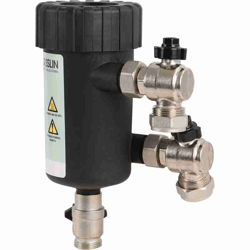
Mag Filter
This is just an empty container, with a powerful NdFeB magnet inserted into the centre. As the water flows in a spiral around the magnetic core, aided by the offset pipe connections, the magnet pulls all the magnetic oxides out of the water. it’s fitted into the circuit at the last radiator, where it’s accessible for the mandatory maintenance.
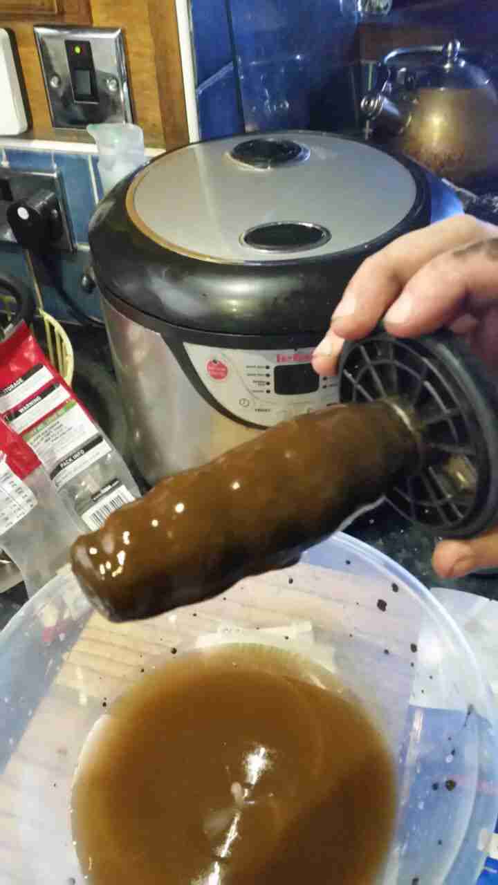
Sludge
Now the filter has been in about a month, I decided it would be a good time to see how much muck had been pulled out of the circuit. I was rather surprised to see a 1/2″ thick layer of sludge coating the magnetic core! The disgusting water in the bowl below was what drained out of the filter before the top was pulled. (The general colour of the water in the circuit isn’t this colour, I knocked some loose from the core of the filter while isolating it).
If all goes well, the level of sludge in the system will over time be reduced to a very low level, with the corrosion inhibitor helping things along. This should result in much fewer expensive pump replacements!
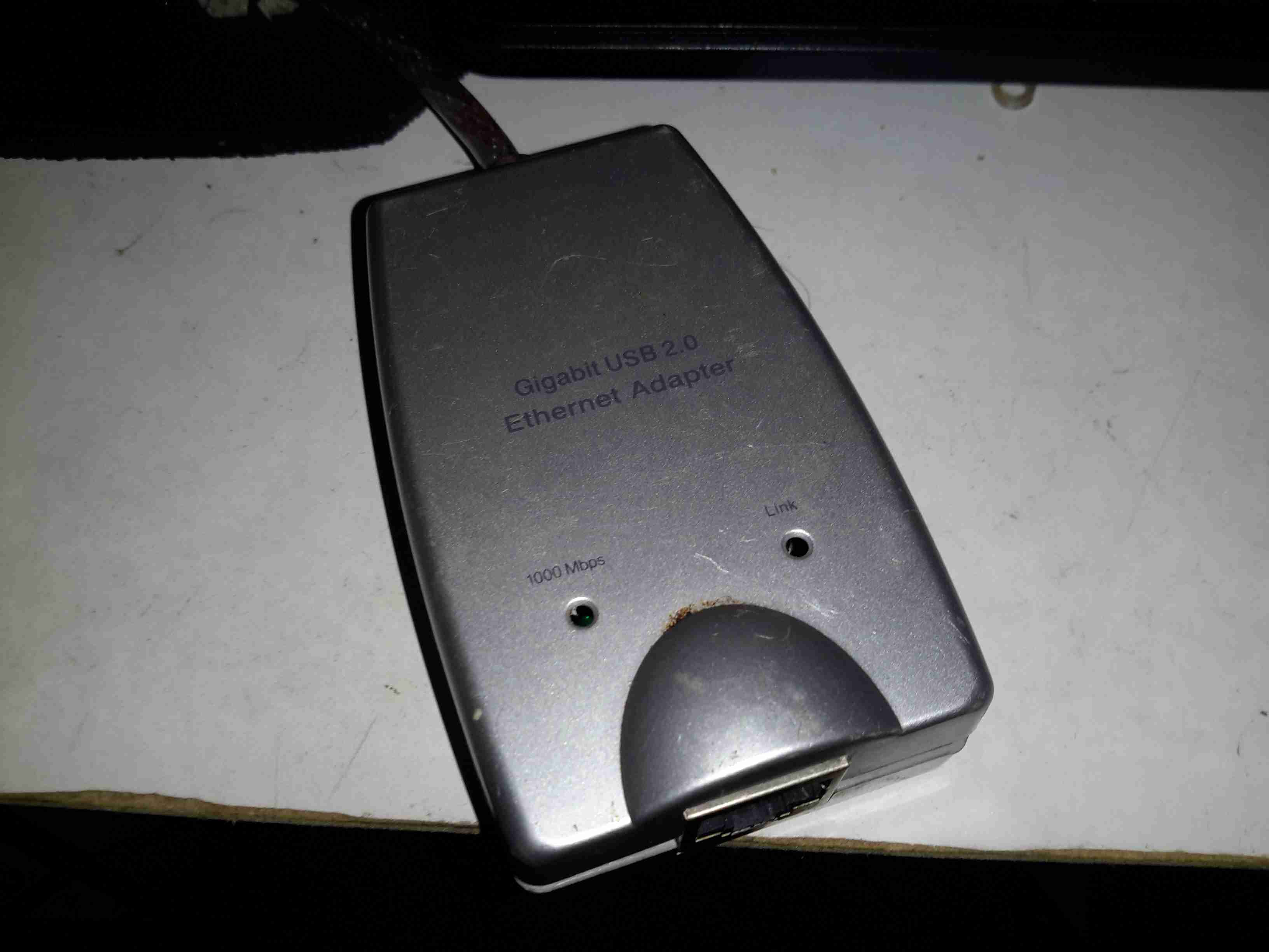
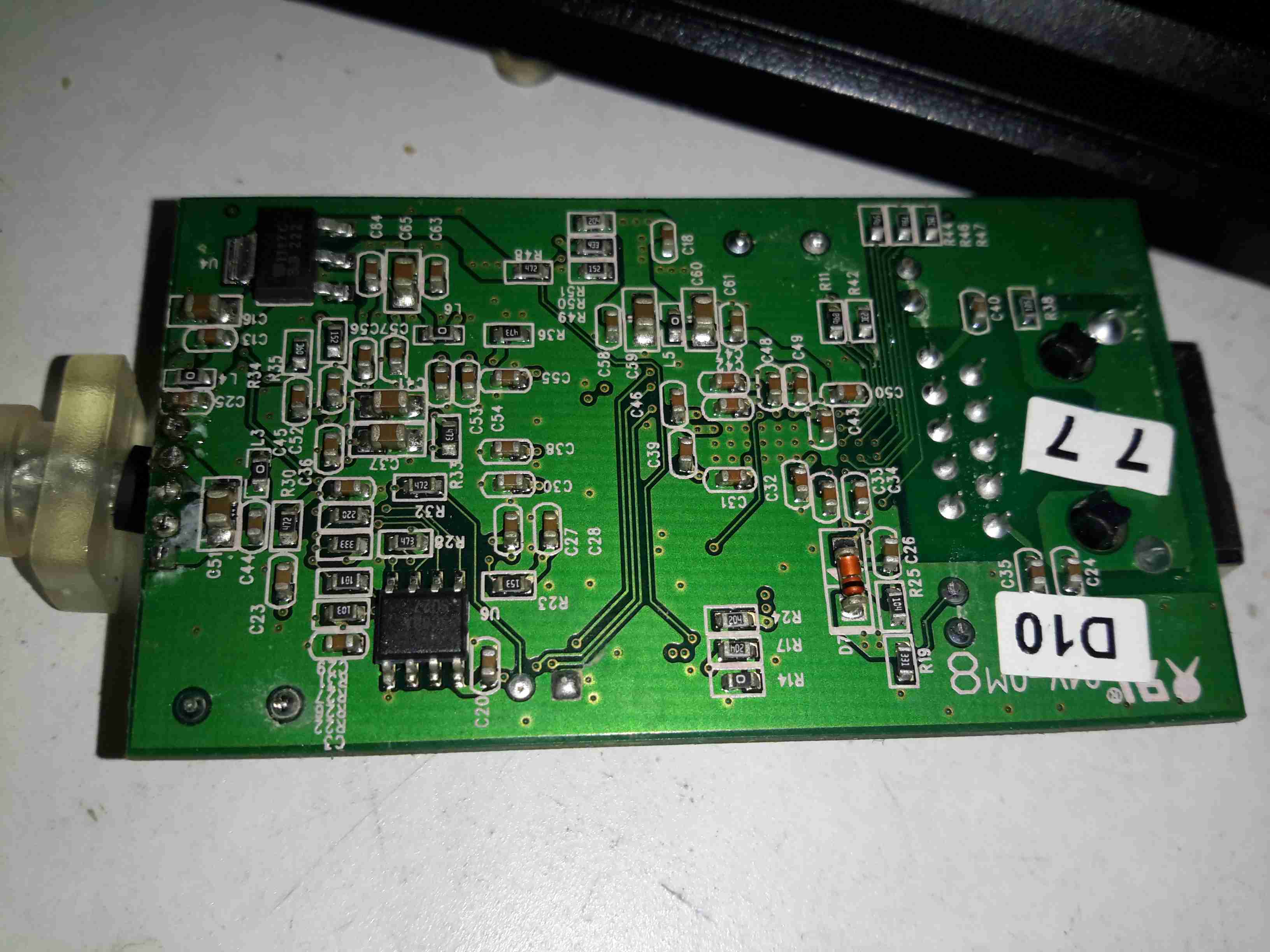
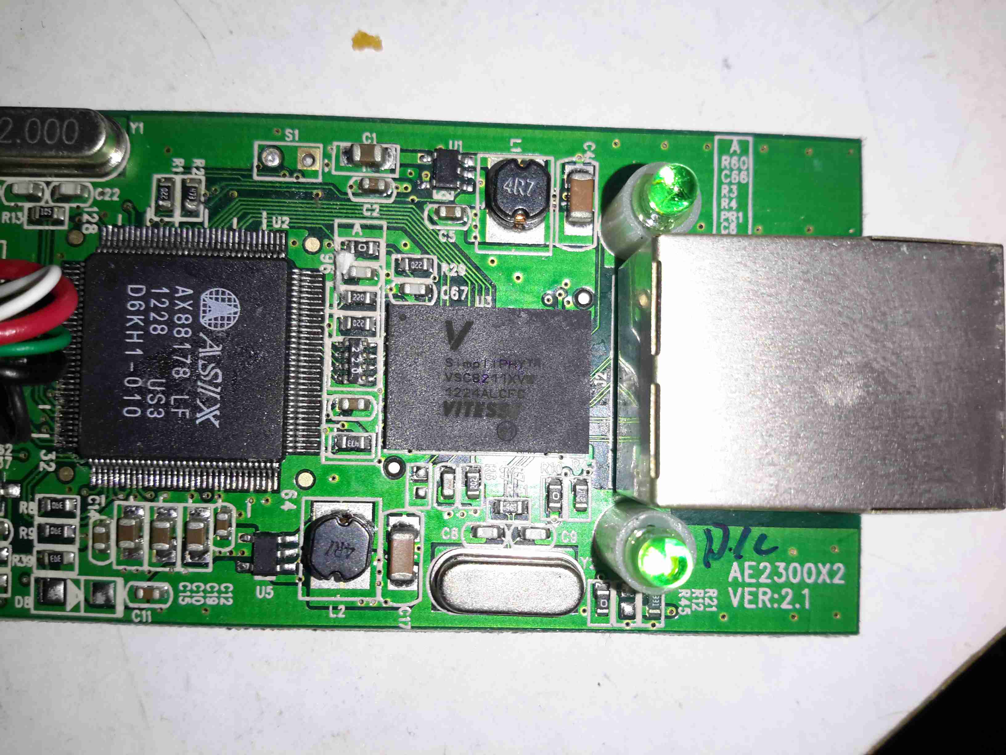
Here’s a chap eBay USB-To-Ethernet dongle I obtained for use with the Raspberry Pi Zero. This one is getting torn down permanently, as it’s rather unreliable. It seems to like having random fits where it’ll not enumerate on the USB bus. The silicon in the ICs will eventually make it here once I manage to get a new microscope 😉
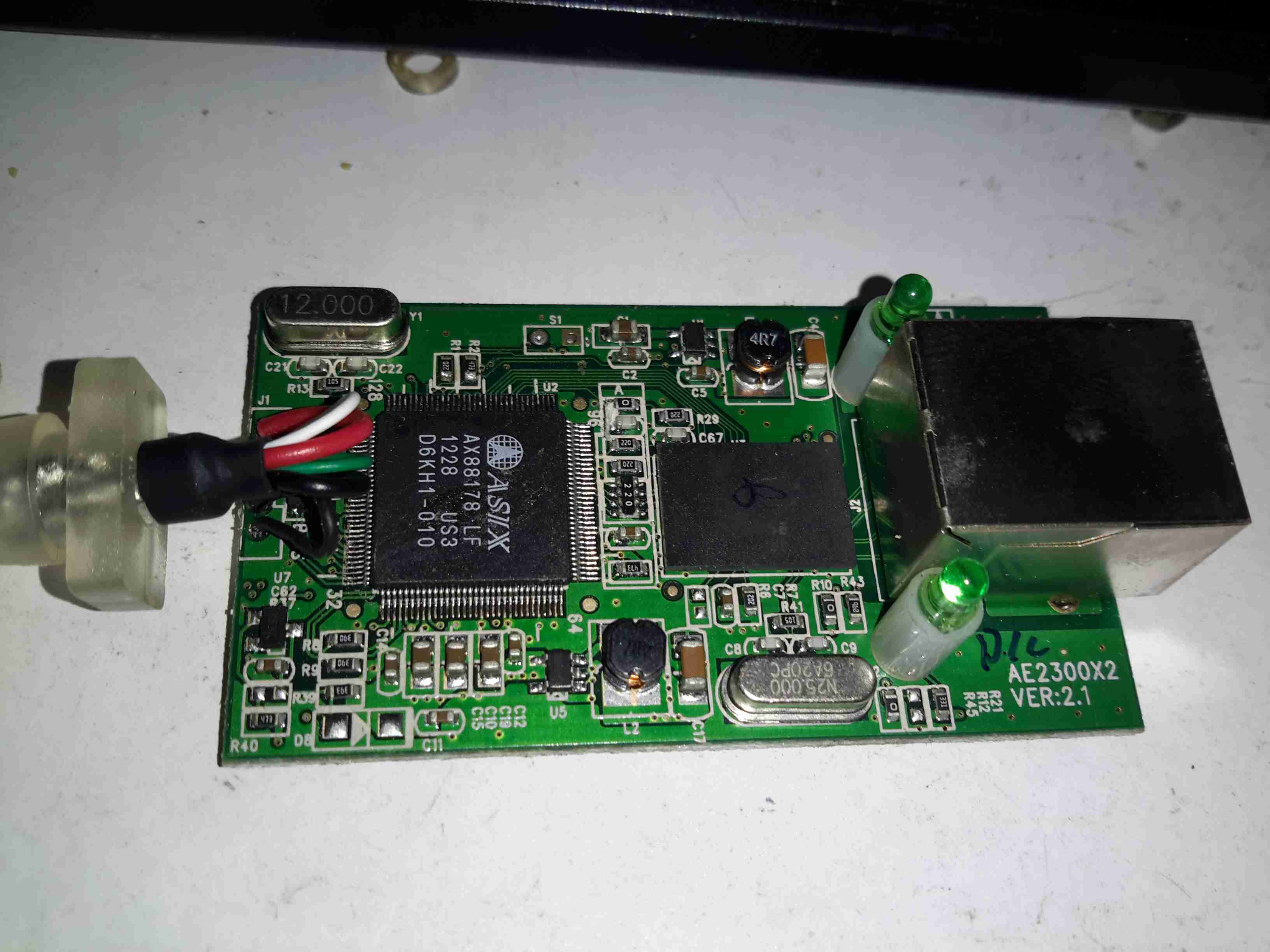
Main Chipset
This is quite a heavily packed PCB, with the main Asix AX88178 on the left. This IC contains all of the logic for implementing the Ethernet link over USB, except the PHY. It’s clock crystal is in the top left corner.
Reverse Side
Not much on the reverse side, there’s a 3.3v linear regulator at top left, the SOIC is an Atmel AT93C66A 4KB EEPROM for configuration data.
Vitesse PHY
The final IC in the chain is the Vitesse VSC8211 Gigabit PHY, with it’s clock crystal below. This interfaces the Ethernet MAC in the Asix IC to the magjack on the right.
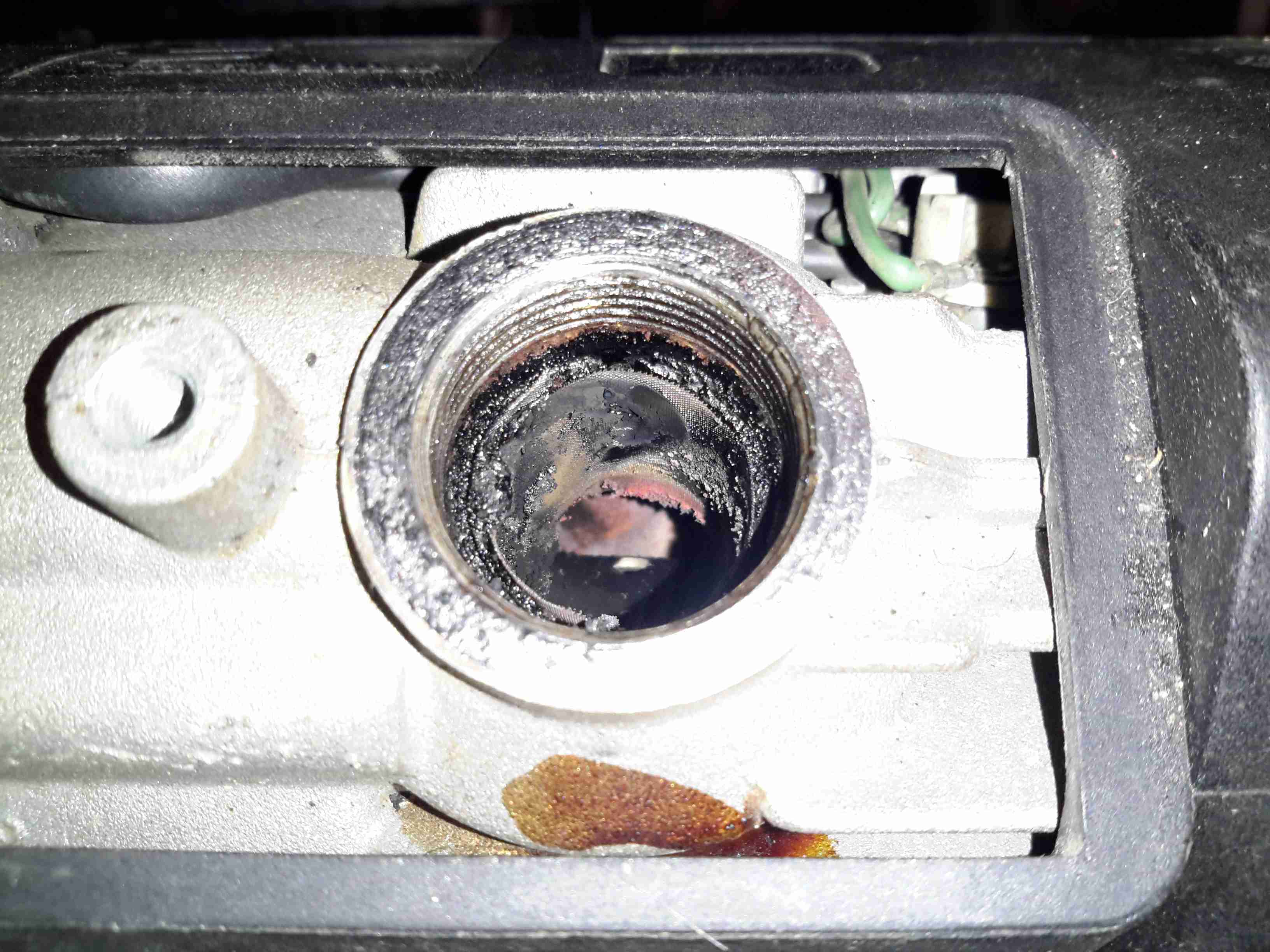
Some time ago I did a couple of posts on cheapening up the maintenance of Eberspacher hot air heaters by making the glow plug screens myself. Now one of my pieces of stainless mesh has been in the heater for nearly a year, and the heater is starting to get a bit smoky on a cold start. This is usually a sign that the screen isn’t allowing the fuel to vaporise quick enough for the glow plug to ignite the flame, because it’s becoming blocked. So far the heater has had about 150L of diesel through it with my DIY screen.
Old Screen
After removing the plug, here’s what’s left of the screen. The bottom end has completely disintegrated, but this is to be expected – OEM screens do the same thing as this end is exposed to the most heat in the burner. There’s quite a bit of coke buildup on the top end of the screen around the fuel nozzle, again this isn’t surprising, as this is the coolest part of the heater not all the heavier fractions of the diesel fuel have the chance to vaporise.
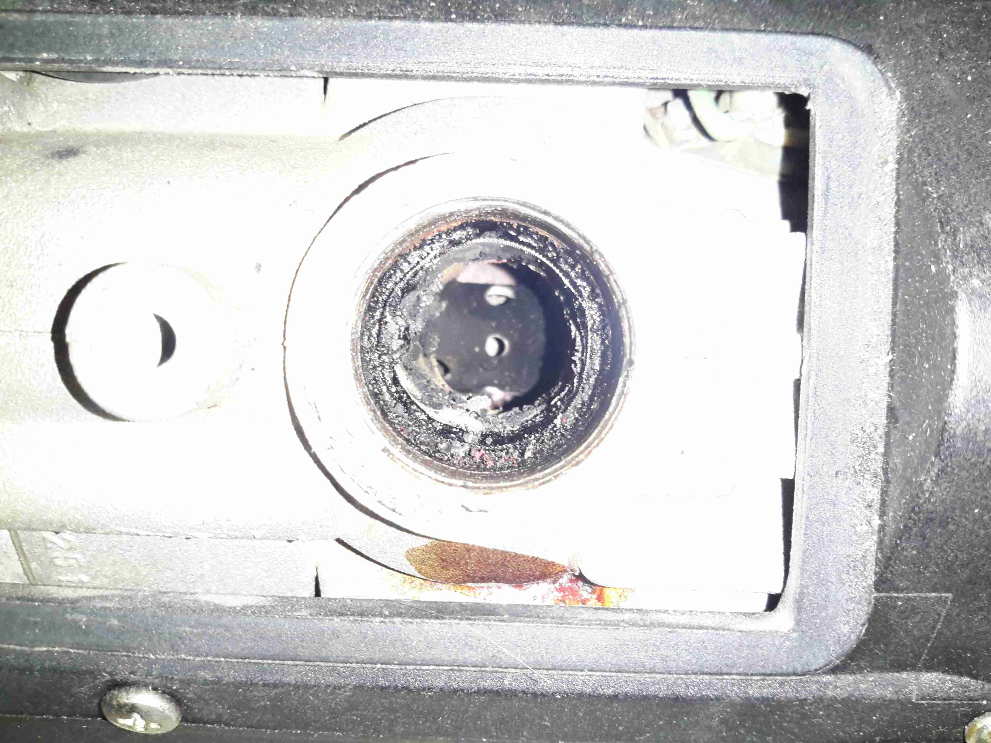
Innards
Looking further down into the mixing tube of the main burner, everything looks good. There’s a coating of soot in there, but no tar-like build up that would tell me the unit isn’t burning properly. Another advantage of making my own screens is that they’re much easier to extract from the hole once they’ve been in there for months. The OEM screens have a stainless ring spot welded to the mesh itself to hold it’s shape, and once there’s enough fuel residue built up the entire mess seizes in place, requiring some sharp pokey tools & some colourful language to remove. The single loop of mesh held in place by it’s own spring pressure is much easier to remove as it collapses easily.
New 80 Mesh Screen
I’ve decided to change the mesh size of the screen while I’m in here, in this case to 80 mesh, which is much closer to the OEM screen size. There doesn’t seem to be much of a difference so far in either the starting or running capability of the heater, although the thicker wire of this screen might last longer before disintegrating at the burner end.
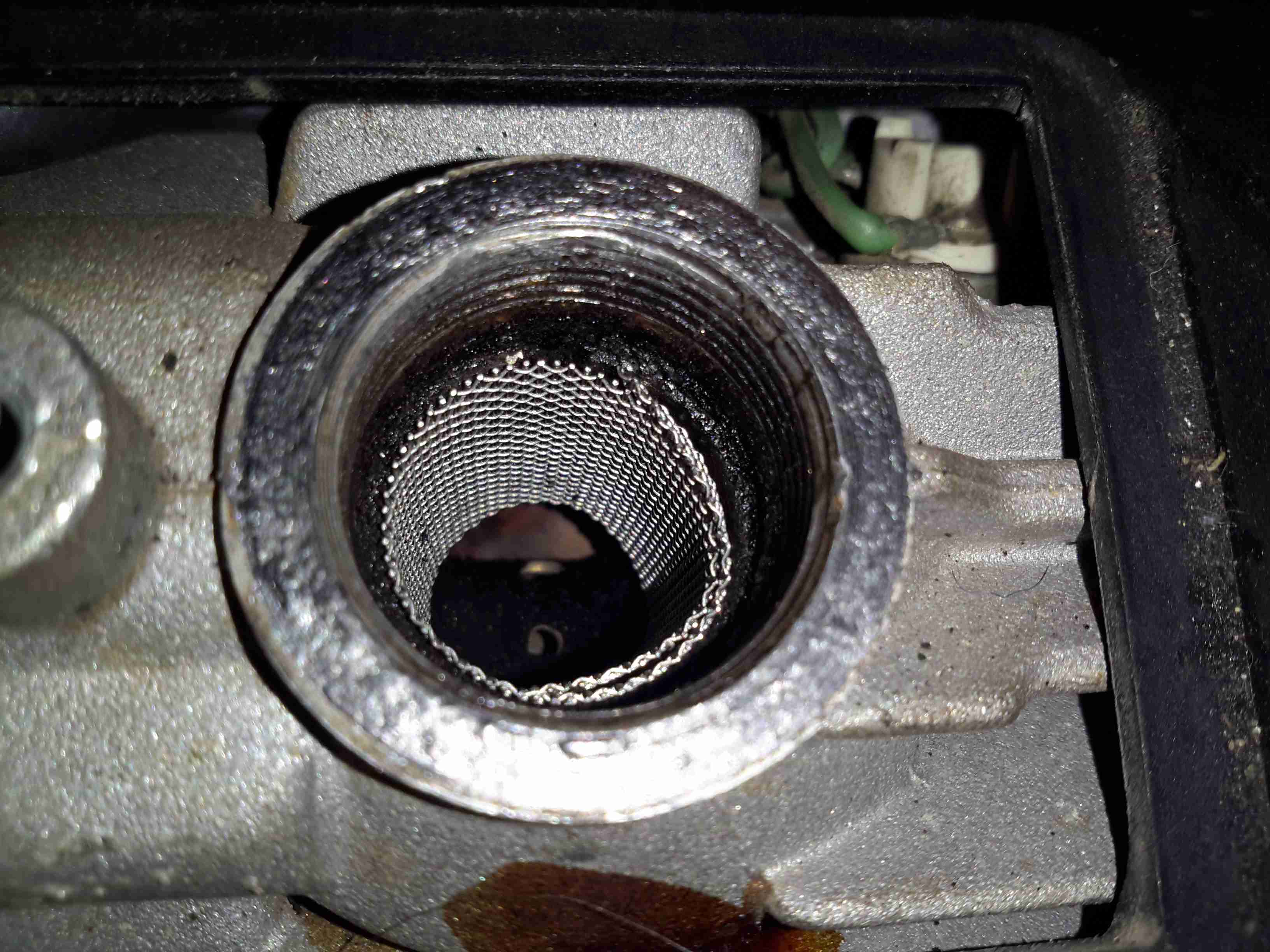
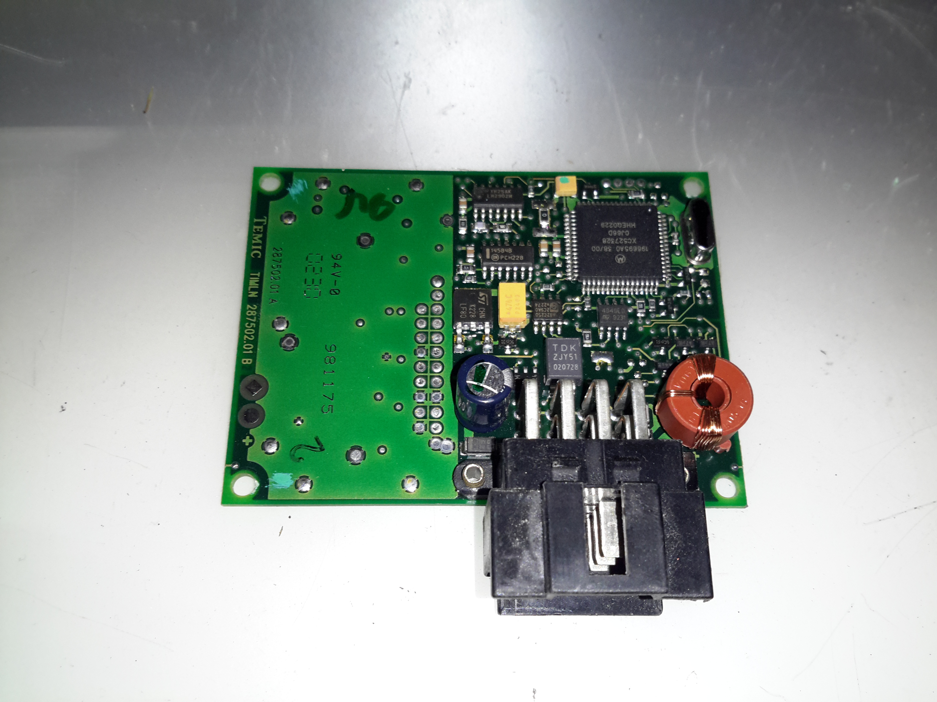
The other day I was given a random pile of car electronic parts from the scrap bin at the local garage, so I decided to do a few teardowns. This first one is a Temic Central Locking / Immobiliser module from a Mercedes van. Judging by the 125kHz stamped on the label, this also has RFID capability.
PCB
The casing just unclips, revealing the PCB. Surprisingly for an automotive module, there is no conformal coating on this (they’re usually heavily coated in protective lacquer to prevent moisture ingress).
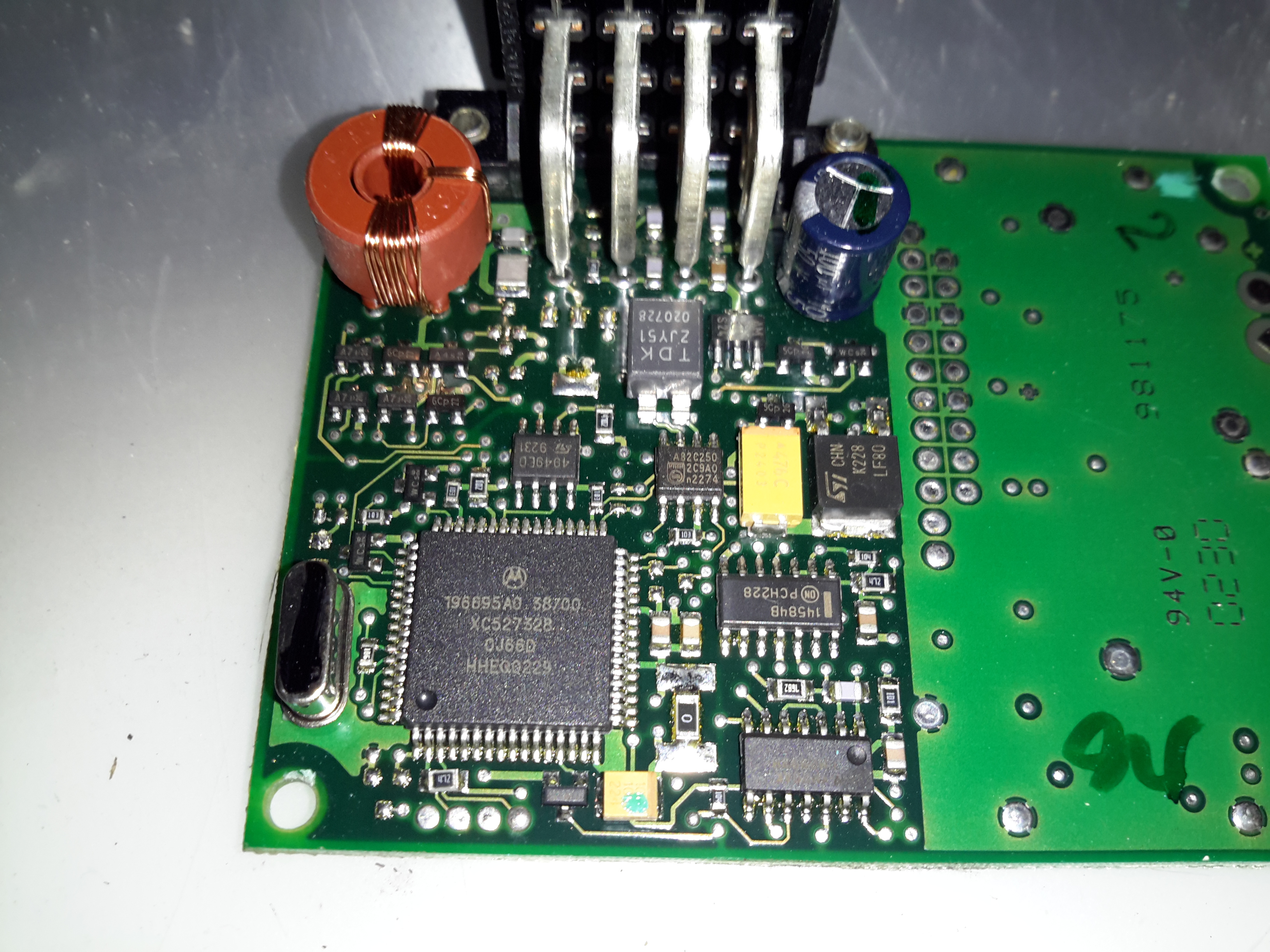
Microcontroller
The large IC from Motorola I’m assuming to be a microcontroller, but I didn’t manage to find anything from the markings. There’s not much else in here apart from some glue logic, and what I think is the 125Khz toroidal antenna in the top left corner.
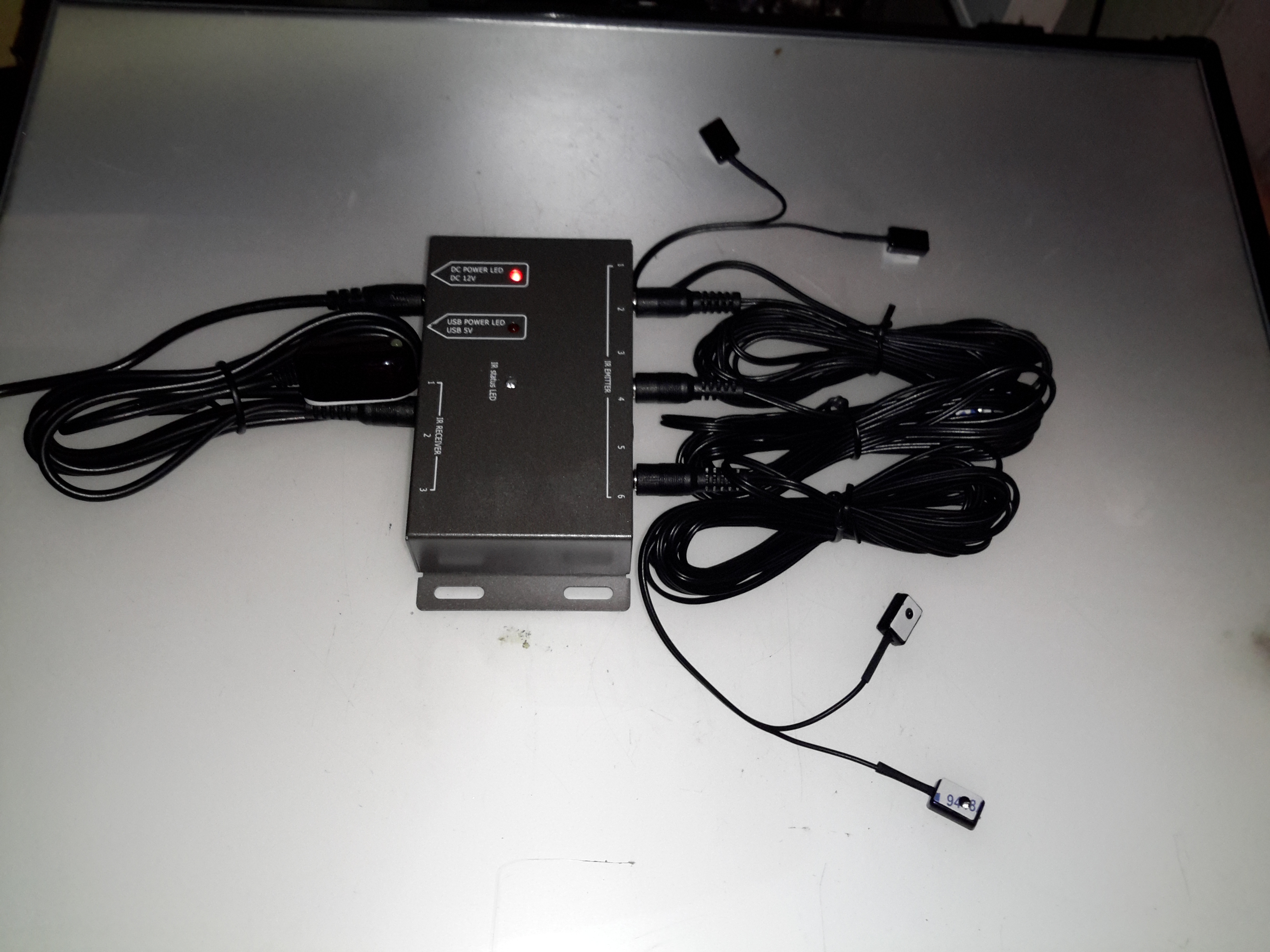
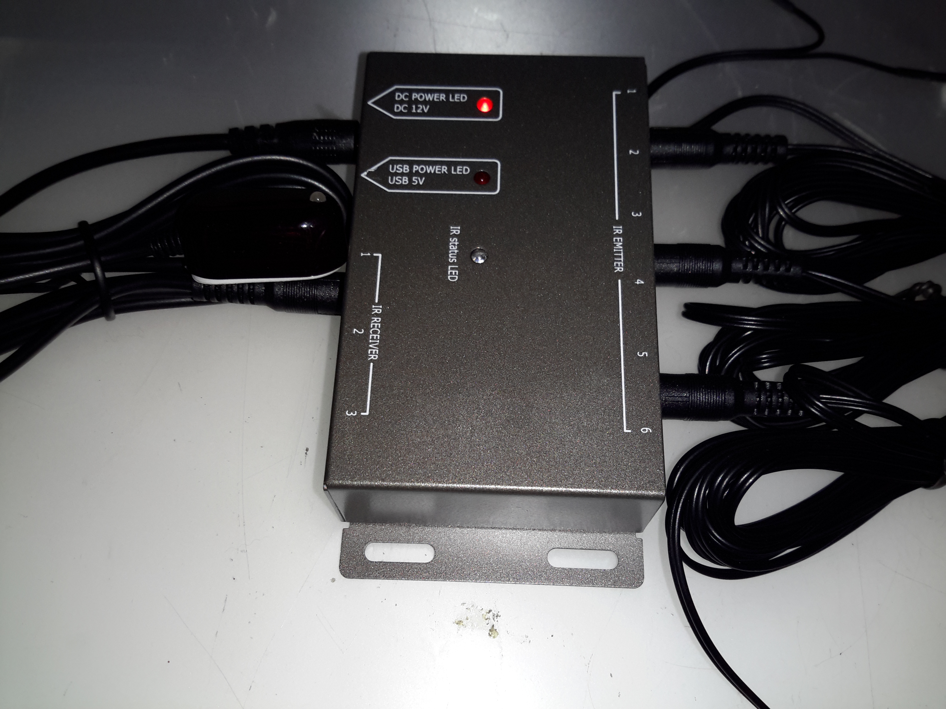
Here’s another random gadget for teardown, this time an IR remote control repeater module. These would be used where you need to operate a DVD player, set top box, etc in another room from the TV that you happen to be watching. An IR receiver sends it’s signal down to the repeater box, which then drives IR LEDs to repeat the signal.
Repeater Module
Not much to day about the exterior of this module, the IR input is on the left, up to 3 receivers can be connected. The outputs are on the right, up to 6 repeater LEDs can be plugged in. Connections are done through standard 3.5mm jacks.
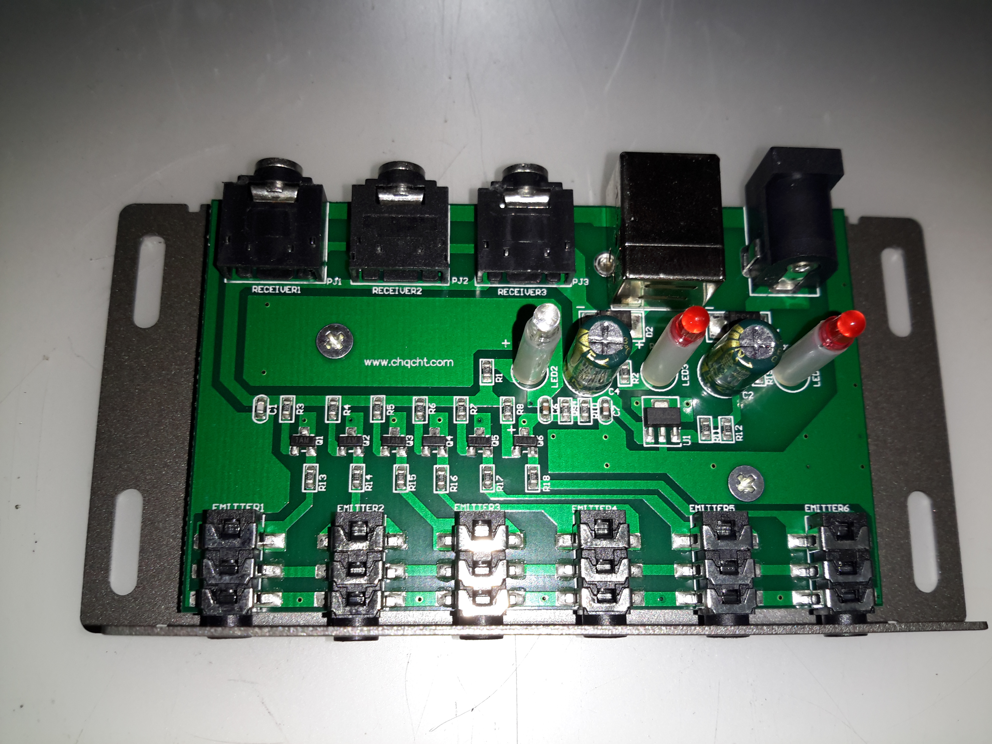
Repeater PCB
Not much inside this one at all, there are 6 transistors which each drive an LED output. This “dumb” configuration keeps things very simple, no signal processing has to be done. Power is either provided by a 12v input, which is fed into a 7805 linear regulator, or direct from USB.
Here’s a piece of medical equipment that in recent years has become extremely cheap, – a Pulse Oximeter, used to determine the oxygen saturation in the blood. These can be had on eBay for less than £15.
Powered On
This one has a dual colour OLED display, a single button for powering on & adjusting a few settings. These cheap Oximeters do have a bit of a cheap plastic feel to them, but they do seem to work pretty well.
Pulse Oximeter
After a few seconds of being applied to a finger, the unit gives readings that apparently confirm that I’m alive at least. 😉 The device takes a few seconds to get a baseline reading & calibrate the sensor levels.
Main PCB Top
The plastic casing is held together with a few very small screws, but comes apart easily. here is the top of the main board with the OLED display panel. There appears to be a programming header & a serial port on the board as well. I’ll have to poke at these pads with a scope to see if any useful data is on the pins.
Main PCB Bottom
The bottom of the board has all the main components of the system. The microcontroller is a STM32F03C8T6, these are very common in Chinese gear these days. There’s a small piezo beeper & the main photodiode detector is in the centre.
There is an unpopulated IC space on the board with room for support components. I suspect this would be for a Bluetooth radio, as there’s a space at the bottom left of the PCB with no copper planes – this looks like an antenna mounting point. (The serial port on the pads is probably routed here, for remote monitoring).
At the top left are a pair of SGM3005 Dual SPDT analogue switches. These will be used to alternate the red & IR LEDs on the other side of the shell.
A 4-core FFC goes off to the other side of the shell, bringing power from the battery & supplying the sensing LEDs.
Battery Compartment
Power is supplied by a pair of AAA cells in the other shell.
Dual LED
The sensor LEDs are tucked in between the cells, this dual-diode package has a 660nm red LED & a 940nm IR LED.
Time foe some more retro tech! This is a 1980’s vintage CCD-based VHS camcorder from Panasonic, the NV-M5. There are a lot of parts to one of these (unlike modern cameras), so I’ll split this post into several sections to make things easier to read (and easier to keep track of what I’m talking about :)).
Left Side
The left side of the camera holds the autofocus, white balance, shutter speed & date controls.
Left Side ControlsLens Adjustments
The lens is fully adjustable, with either manual or motorized automatic control.
Rear Panel
The back panel has the battery slot, a very strange looking DC input connector, remote control connector & the earphone jack.
Top Controls
The top panel of the camera holds the main power controls, manual tape tracking & the tape transport control panel.
Viewfinder
The viewfinder is mounted on a swivel mount. There’s a CRT based composite monitor in here. Hack ahoy!
Camera Section
Process Board Assembly
Here’s the camera section of the camcorder, and is totally packed with electronics! There’s at least half a dozen separate boards in here, all fitted together around the optics tube assembly.
AWB PCB
On the top of the assembly is the Automatic White Balance PCB. Many adjustments here to get everything set right. Not much on the other side of this board other than a bunch of Op-Amps. The iris stepper motor is fitted in a milled opening in the PCB, this connects to one of the other PCBs in the camera module.
AWB Sensor
Here’s the AWB sensor, mounted next to the lens. I’m not all to certain how this works, but the service manual has the pinout, and there are outputs for all the colour channels, RGB. So it’s probably a trio of photodiodes with filters.
Focus & Zoom Motors
Focus & Zoom are controlled with a pair of DC gear motors. The manual operation is feasible through the use of slip clutches in the final drive pinion onto the lens barrel.
Process Board
The main camera section process board is above. This board does all the signal processing for the CCD, has the bias voltage supplies and houses the control sections for the motorized parts of the optics assembly. There are quite a few dipped Tantalum capacitors on pigtails, instead of being directly board mounted. This was probably done due to space requirements on the PCB itself.
Under the steel shield on this board is some of the main signal processing for the CCD.
Optics Assembly
The back of the optics tube is a heavy casting, to supress vibration. This will be more clear later on.
Position Sensor Flex
The position of the lens elements is determined by reflective strips on the barrel & sensors on this flex PCB.
Sub Process Board
There’s another small board tucked into the side of the tube, this hooks into the process PCB.
Process Delay Line
According to the schematic, there’s nothing much on this board, just a delay line & a few transistors.
Piezo Focus Disc
Here’s the reason for the heavy alloy casing at the CCD mounting end of the optics: the fine focus adjustment is done with a piezoelectric disc, the entire CCD assembly is mounted to this board. Applying voltage to the electrodes moves the assembly slightly to alter the position of the CCD. The blue glass in the centre of the unit is the IR filter.
IR Relective Sensors
The barrel position sensors are these IR-reflective type.
Iris Assembly
The iris is mounted just before the CCD, this is controlled with a galvanometer-type device with position sensors incorporated.
Iris Opening
Pushing on the operating lever with the end of my screwdriver opens the leaves of the iris against the return spring.
Tape Transport & Main Control
Main Control Board
Tucked into the side of the main body of the unit is the main system control board. This PCB houses all the vital functions of the camera: Power Supply, Servo Control, Colour Control,Video Amplifiers, etc.
Tape Drum
Here’s the main tape transport mechanism, this is made of steel & aluminium stampings for structural support. The drum used in this transport is noticeably smaller than a standard VHS drum, the tape is wrapped around more of the drum surface to compensate.
Tape Transport
The VHS tape sits in this carriage & the spools drive the supply & take up reels in the cartridge.
Main Control PCB
Here’s the component side of the main control PCB. This one is very densely packed with parts, I wouldn’t like to try & troubleshoot something like this!
Main PCB Left
The left side has the video head amp at the top, a Panasonic AN3311K 4-head video amp. Below that is video processing, the blue components are the analogue delay lines. There are a couple of hybrid flat-flex PCBs tucked in between with a couple of ICs & many passives. These hybrids handle the luma & chroma signals.
Top left is the capstan motor driver a Rohm BA6430S. The transport motors are all 3-phase brushless, with exception of the loading motor, which is a brushed DC type.
Delay Line
Here’s what is inside the delay lines for the analogue video circuits. The plastic casing holds a felt liner, inside which is the delay line itself.
Internal Glass
The delay is created by sending an acoustic signal through the quartz crystal inside the device by a piezoelectric transducer, bouncing it off the walls of the crystal before returning it to a similar transducer.
Main PCB Centre
Here’s the centre of the board, the strange crystal at bottom centre is the clock crystal for the head drum servo. Why it has 3 pins I’m not sure, only the two pins to the crystal inside are shown connected on the schematic. Maybe grounding the case?
The main servo controls for the head drum & the capstan motor are top centre, these get a control signal from the tape to lock the speed of the relative components.
Main PCB Right
Here’s the right hand side. The main power supply circuitry is at top right, with a large can containing 4 switching inductors & a ferrite pot core transformer. All these converters are controlled by a single BA6149 6-channel DC-DC converter controller IC via a ULN2003 transistor array.
The ceramic hybrid board next to the PSU has 7 switch transistors for driving various indicator LEDs.
The large tabbed IC bottom centre is the loading motor drive, an IC from Mitsubishi, the M54543. This has bidirectional DC control of the motor & built in braking functions. The large quad flat pack IC on the right is the MN1237A on-screen character generator, with the two clock crystals for the main microcontroller.
Erase Head
The full erase head has it’s power supply & oscillator on board, applying 9v to this board results in an AC signal to the head, which erases the old recording from the tape before the new recording is laid down by the flying heads on the drum.
Audio Control PCB
The Audio & Control head is connected to this PCB, which handles both reading back audio from the tape & recording new audio tracks. The audio bias oscillator is on this board, & the onboard microphone feeds it’s signal here. The control head is fed directly through to the servo section of the main board.
Drum Motor
The motor that drives the head drum is another DC brushless 3-phase type.
Hall Sensors
These 3 Hall sensors are used by the motor drive to determine the rotor position & time commutation accordingly.
Stator
The stator on this motor is of interesting construction, with no laminated core, the coils are moulded into the plastic holder. The tach sensor is on the side of the stator core. This senses a small magnet on the outside of the rotor to determine rotational speed. For PAL recordings, the drum rotates at 1500 RPM.
Motor Removed
Not much under the stator other than the bearing housing & the feedthrough to the rotary transformer.
Head Disc
The heads are mounted onto the top disc of the drum, 4 heads in this recorder. The signals are transmitted to the rotating section through the ferrite rotary transformer on the bottom section.
Head Chip
The tiny winding of the ferrite video head can just about be seen on the end of the brass mounting.
Capstan Motor Components
The capstan motor is similar to the drum motor, only this one is flat. The rotor has a ferrite magnet, in this case it wasn’t glued in place, just held by it’s magnetic field.
Capstan Motor Stator
The PCB on this motor has a steel backing to complete the magnetic circuit, the coils for the 3 motor phases are simply glued in place. The Hall sensors on this motor are placed in the middle of the windings though.
Again there is a tach sensor on the edge of the board that communicates the speed back to the controller. This allows the servo to remain locked at constant speed.
Viewfinder
Viewfinder Assembly
As usual with these cameras, this section is the CRT based viewfinder. These units take the composite signal from the camera to display the scene. This one has many more pins than the usual viewfinder. I’ll hack a manual input into this, but I’ll leave that for another post.
Viewfinder Circuits
Being an older camera than the ones I’ve had before, this one is on a pair of PCBs, which are both single-sided.
Main Viewfinder Board
The main board has all the power components for driving the CRT & some of the adjustments. The main HV flyback transformer is on the right. This part creates both the final anode voltage for the tube & the focus/grid voltages.
Viewfinder Control PCB Top
The viewfinder control IC is on a separate daughter board in this camera, with two more controls.
Control IC
The control IC is a Matsushita AN2510S, this has all the logic required to separate the sync pulses from the composite signal & generate an image on the CRT.
Viewfinder CRT Frame
The recording indicator LEDs are mounted in the frame of the CRT & appear above the image in the viewfinder.
Viewfinder CRT With Yoke
Here the CRT has been separated from the rest of the circuitry with just the deflection yoke still attached.
M01JPG5WB CRT
The electron gun in this viewfinder CRT is massive in comparison to the others that I have seen, and the neck of the tube is also much wider. These old tubes were very well manufactured.
Viewfinder Optics
A simple mirror & magnifying lens completes the viewfinder unit.
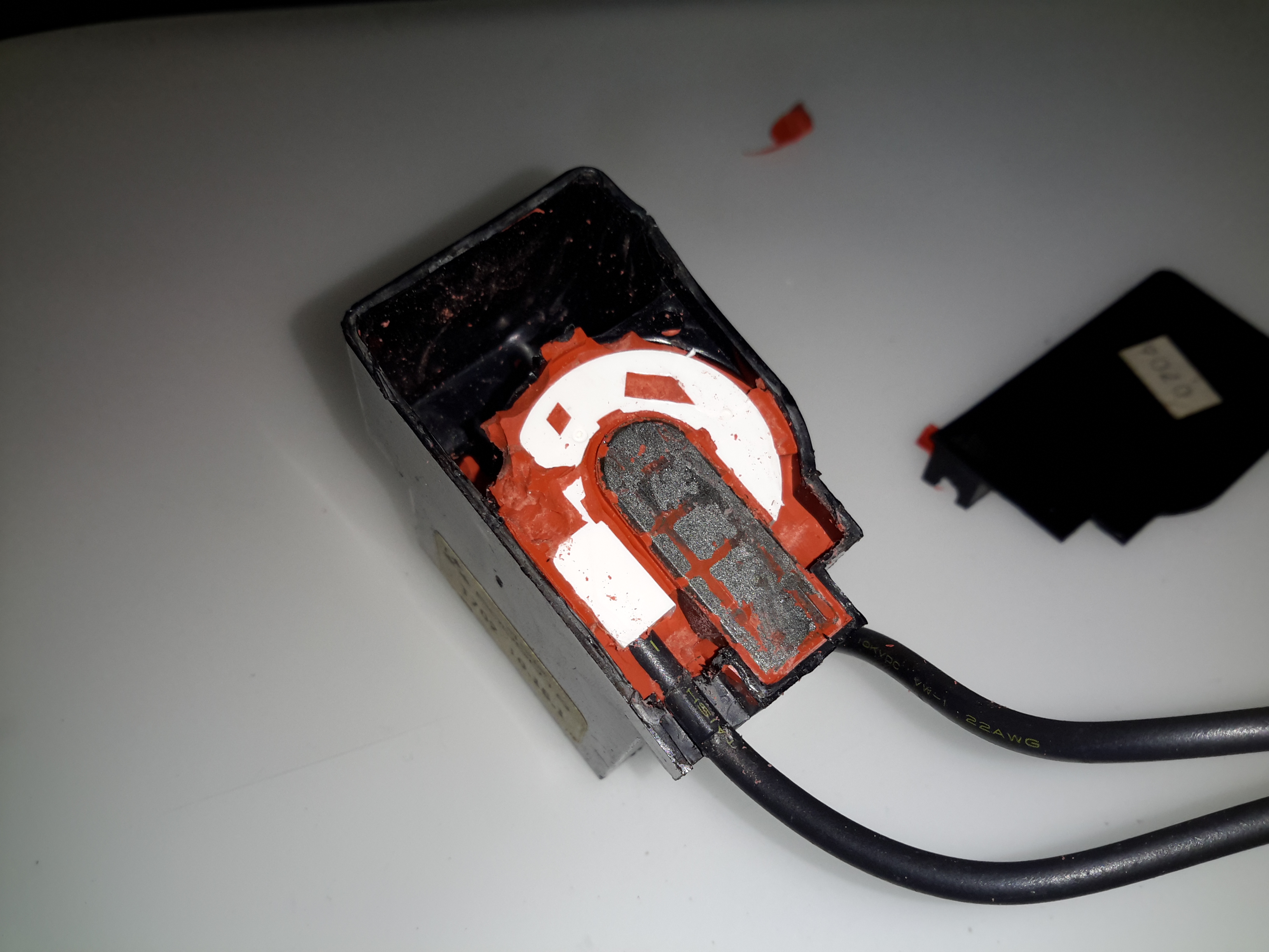
Here’s a small flyback / Line Output Transformer from a portable colour TV set. Usually these transformers are vacuum potted in hard epoxy resin & are impossible to disassemble without anything short of explosives. (There are chemical means of digesting cured epoxies, but none of them are pleasant). This one however, was potted in silicone, so with some digging, the structure of the transformer can be revealed.
Cap Removed
The cap was glued on to the casing, but this popped off easily. The top of the core is visible in the silicone potting material.
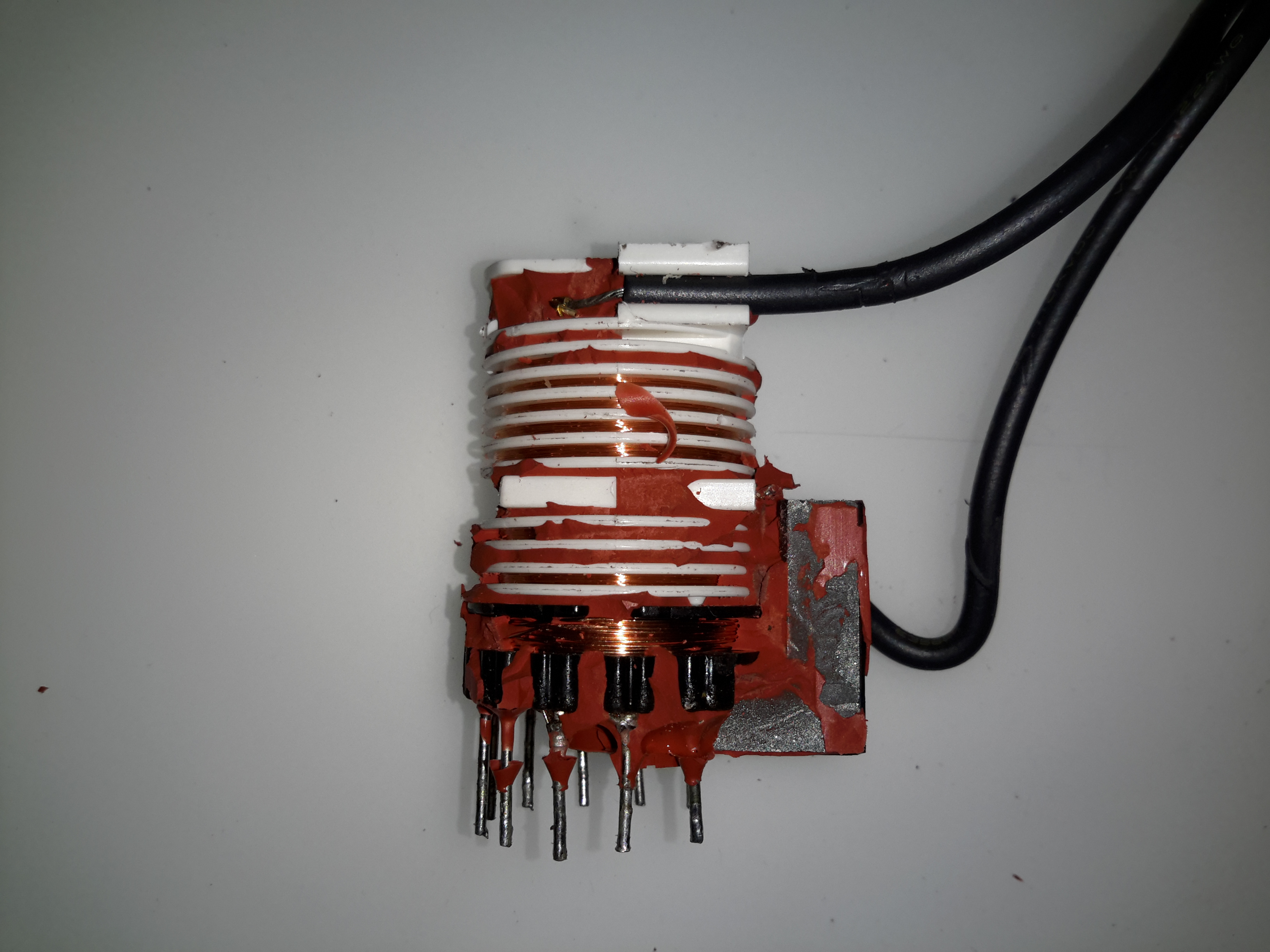
The Digging Starts
A small screwdriver was used to remove the potting material, while trying not to damage the winding bobbin & core too badly. The bulge in the casing that I originally thought might house a voltage multiplier turns out to be totally empty. The white plastic bobbin is becoming visible around the core.
Bobbin
After some more digging & a lot of mess later, the entire transformer is revealed. The primary & auxiliary secondaries are visible at the bottom of the transformer, next to the pins. These transformers have multiple windings, as they’re used not only for supplying the final anode voltage of several Kilovolts to the CRT, but many of the other associated voltages, for the heater, grids, focus electrodes, etc. These lower voltage windings are on the same part of the core as the primary.
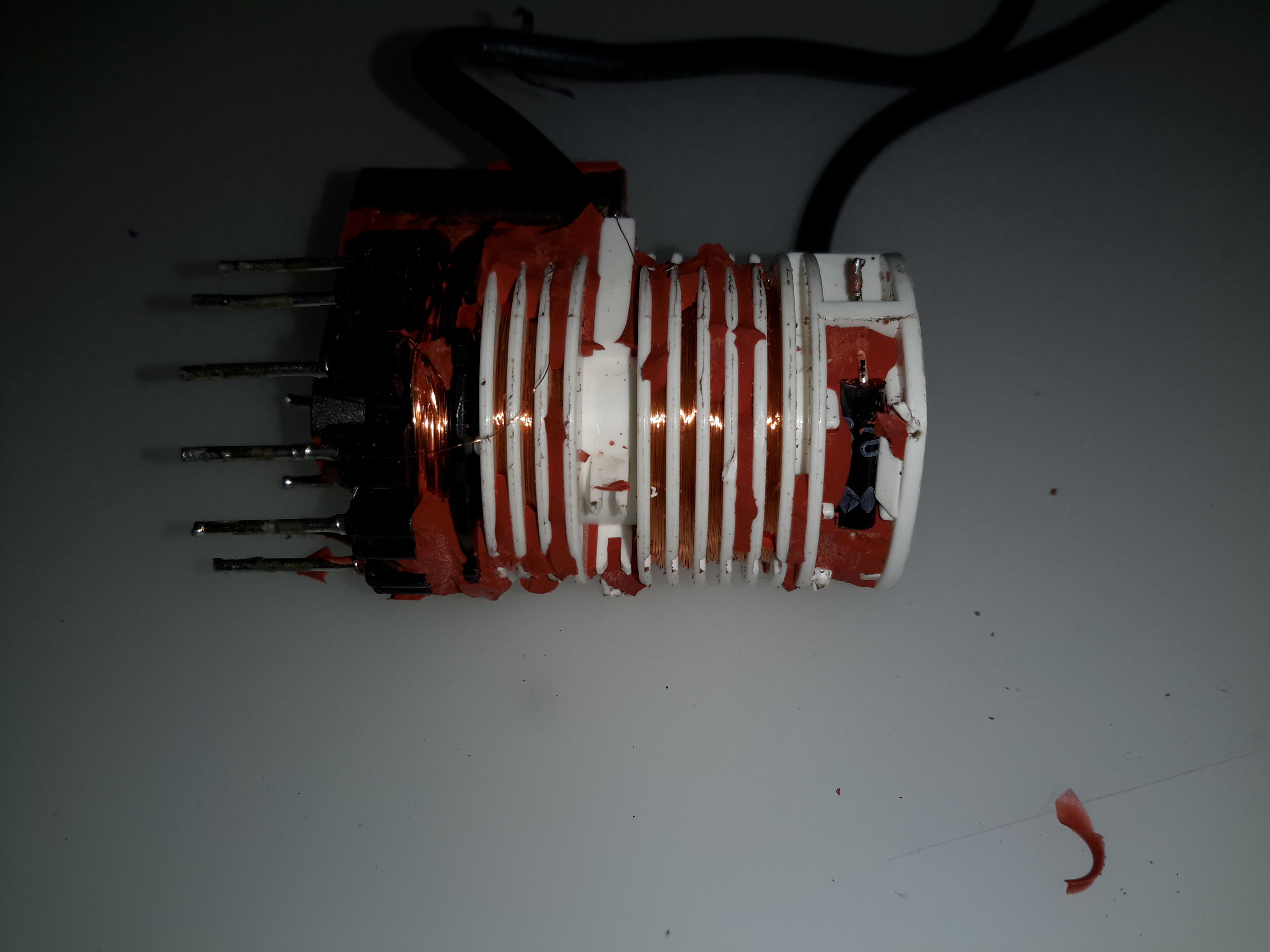
Above those is the main high voltage secondary winding, which looks to be wound with #38-#40AWG wire (about the thinnest available, at 0.07mm diameter. This is wound in many sections of of a few hundred turns each to increase the insulation resistance to the high voltage. The main anode wire emerges from the top of the bobbin.
Output Rectifier
Hidden in a recess at the top is the main HV rectifier, which on this small transformer is a single device (it’s probably not internally, most likely a series stack of diodes to get the PIV rating required).
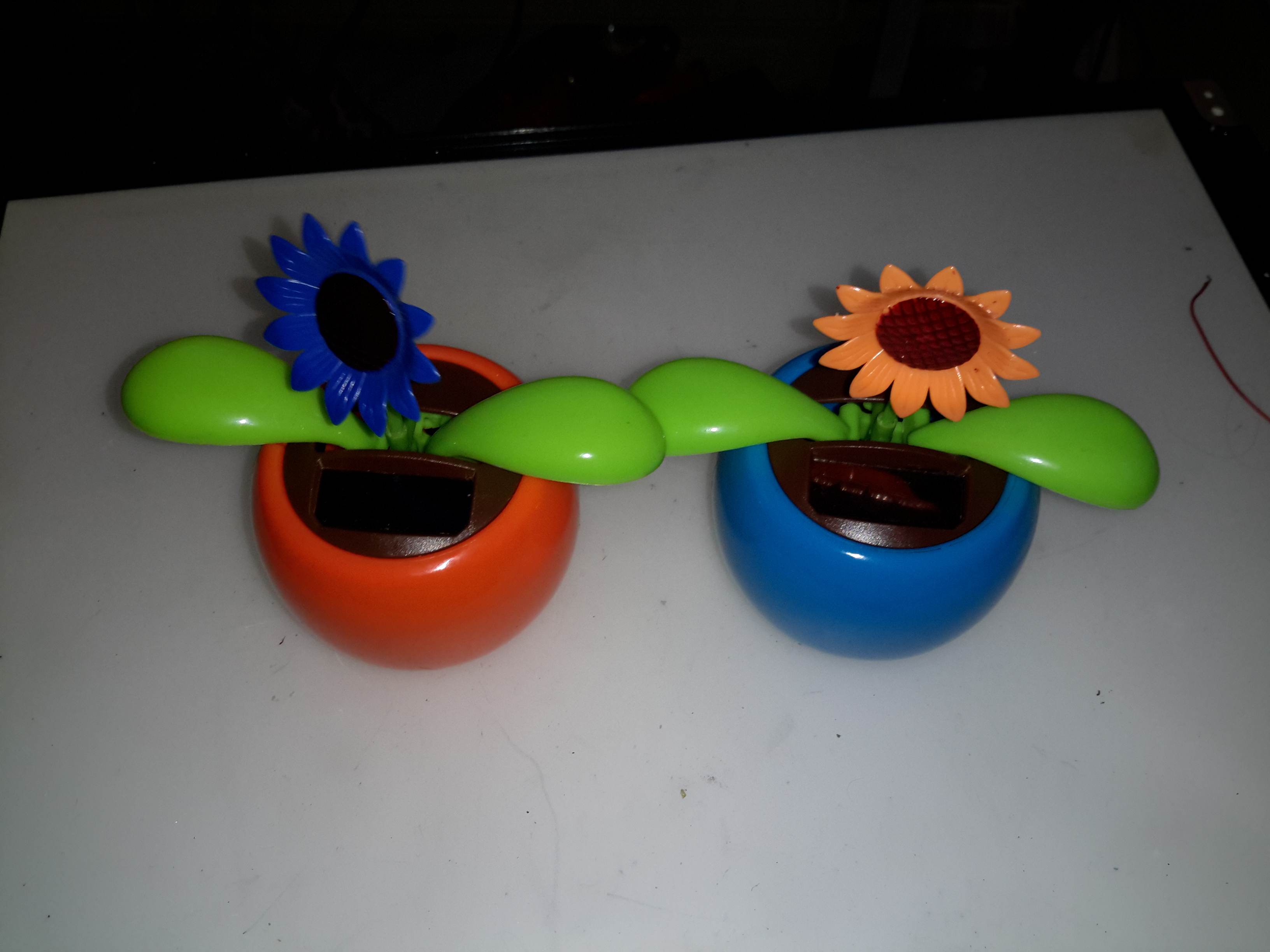
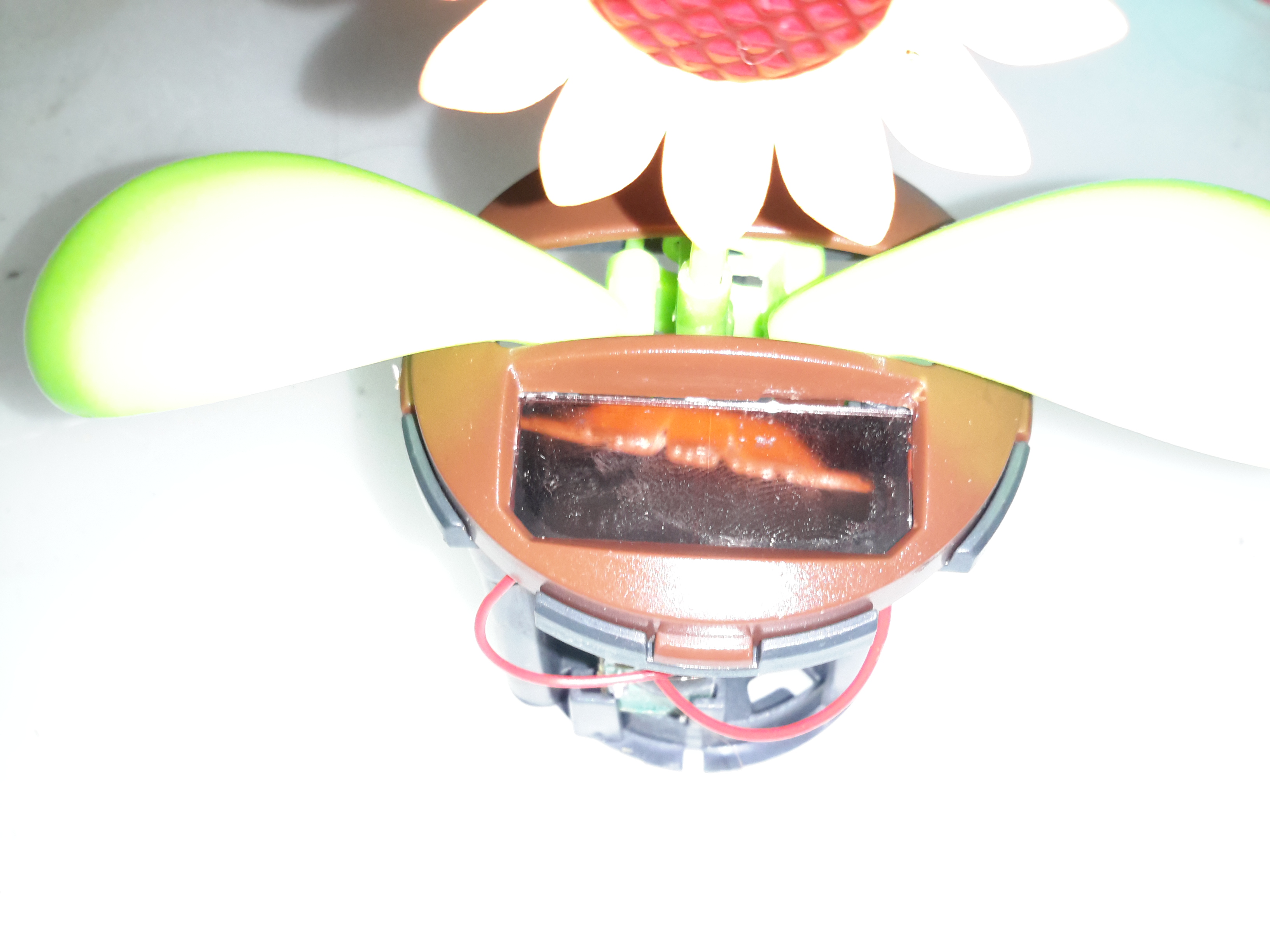
These solar flowers were being sold off at my local Tesco, a pair of them appeared thanks to my child 😉
They have a small solar panel on top, when they’re exposed to bright light, the flower & leaves move as if they’re being blown in a breeze.
Since one of them didn’t work, I figured I’d tear it down.
Solar Cell
The solar cell on the top is similar if not identical to that used on a cheap calculator.
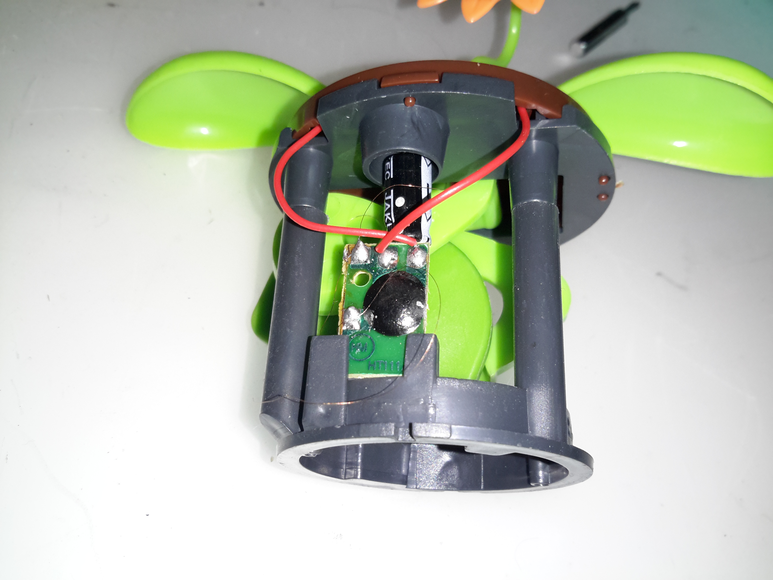
Controller
Not much to the control PCB. Just an electrolytic for smoothing the DC coming from the solar cell & a COB IC.
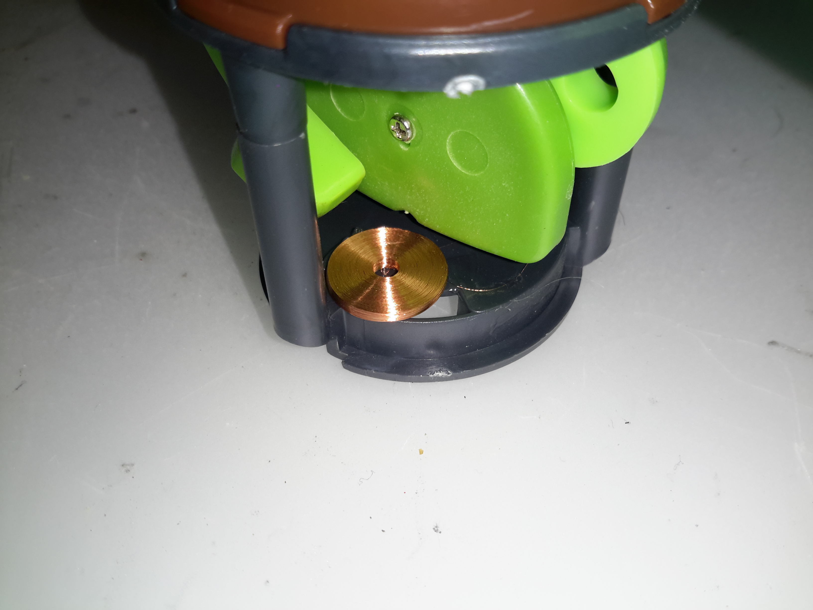
Electromagnet Coil
The IC drives this coil of extremely fine wire, glued to the base of the housing. Attached to the green plastic arm should be a magnet – this one has never worked as the magnet is missing. at 50p a piece, a magnet would cost me more than the whole device. So it’s the bin for this one.
Tip Jar
If you’ve found my content useful, please consider leaving a donation by clicking the Tip Jar below!
All collected funds go towards new content & the costs of keeping the server online.