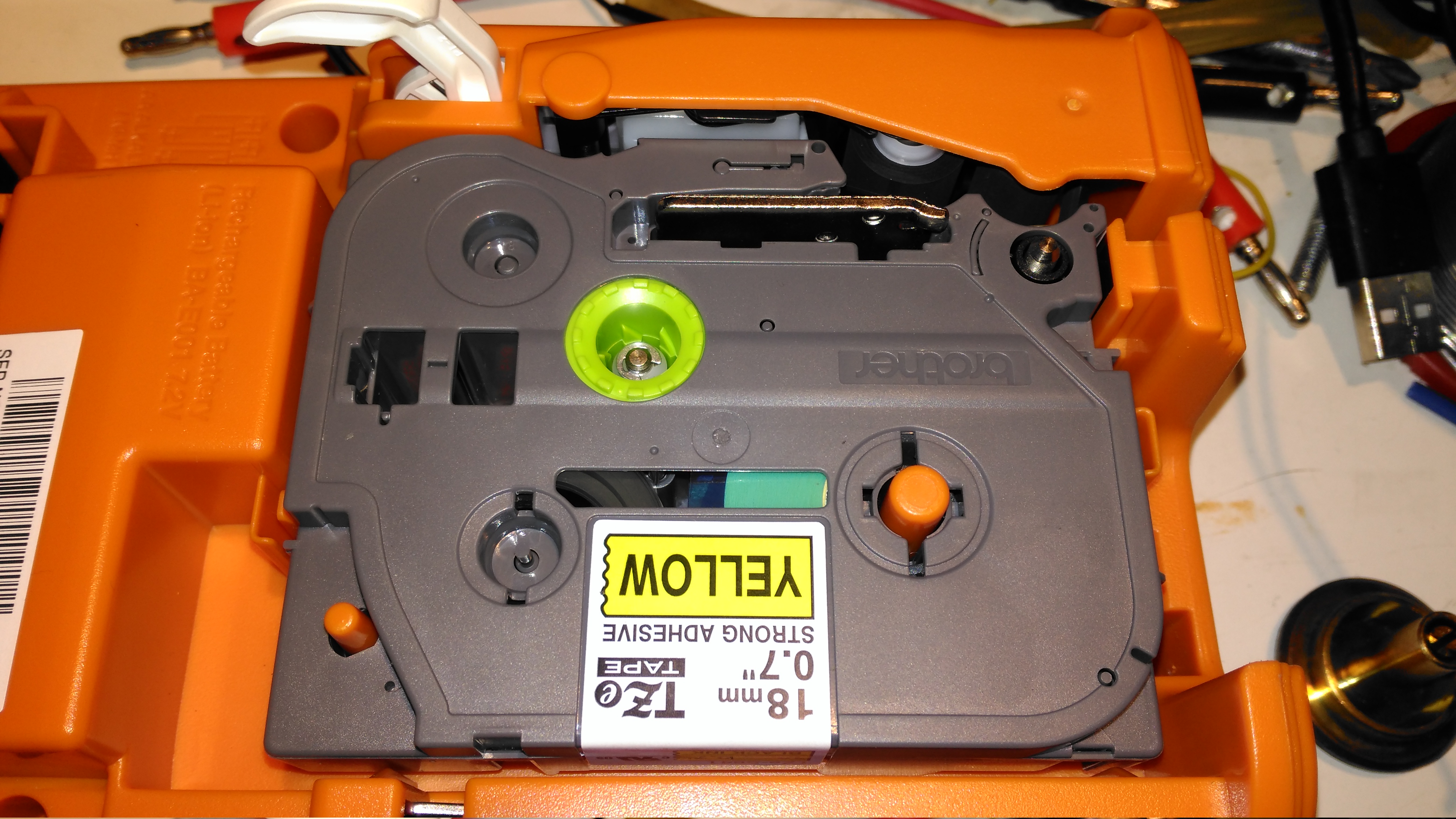
Here a tape is installed in the printer. This unit can handle tape widths up to 18mm. The pinch rollers are operated by the white lever at the top of the image, which engages with the back cover.
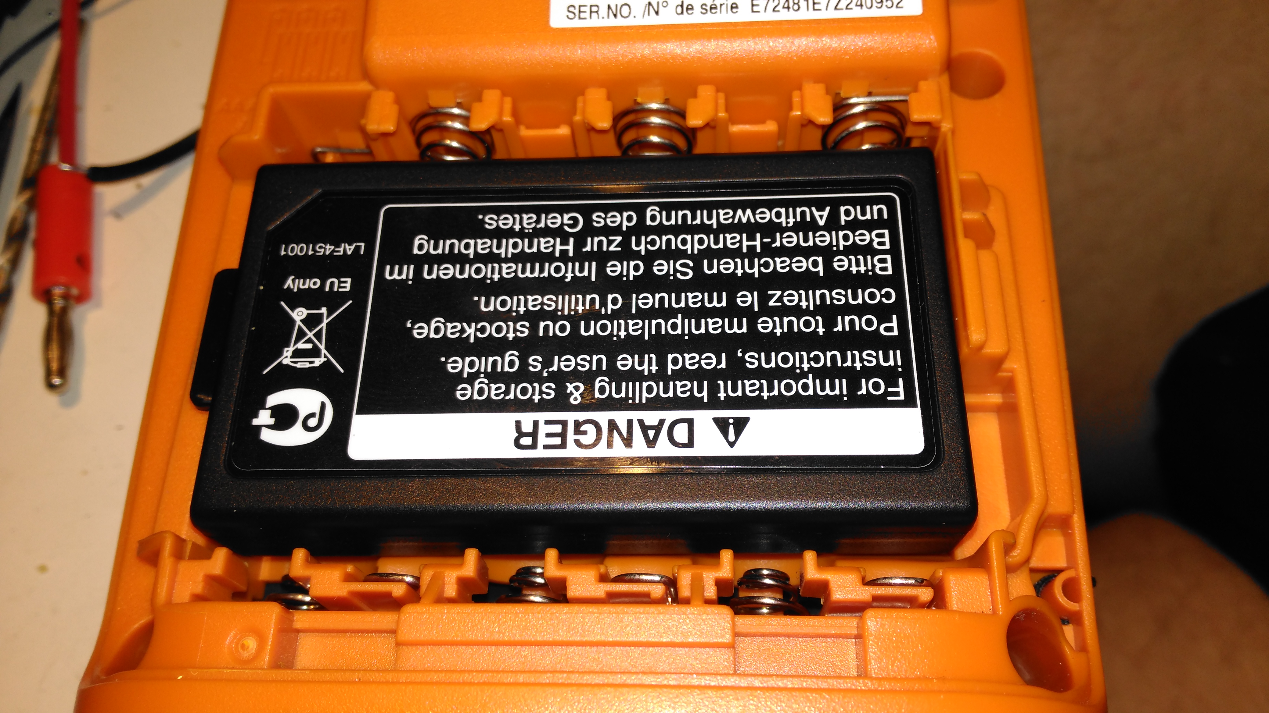
Li-Ion Battery
This printer is supplied with a rechargeable battery pack, but AA cells can be used as well. Some of the AA battery terminals can be seen above the battery.
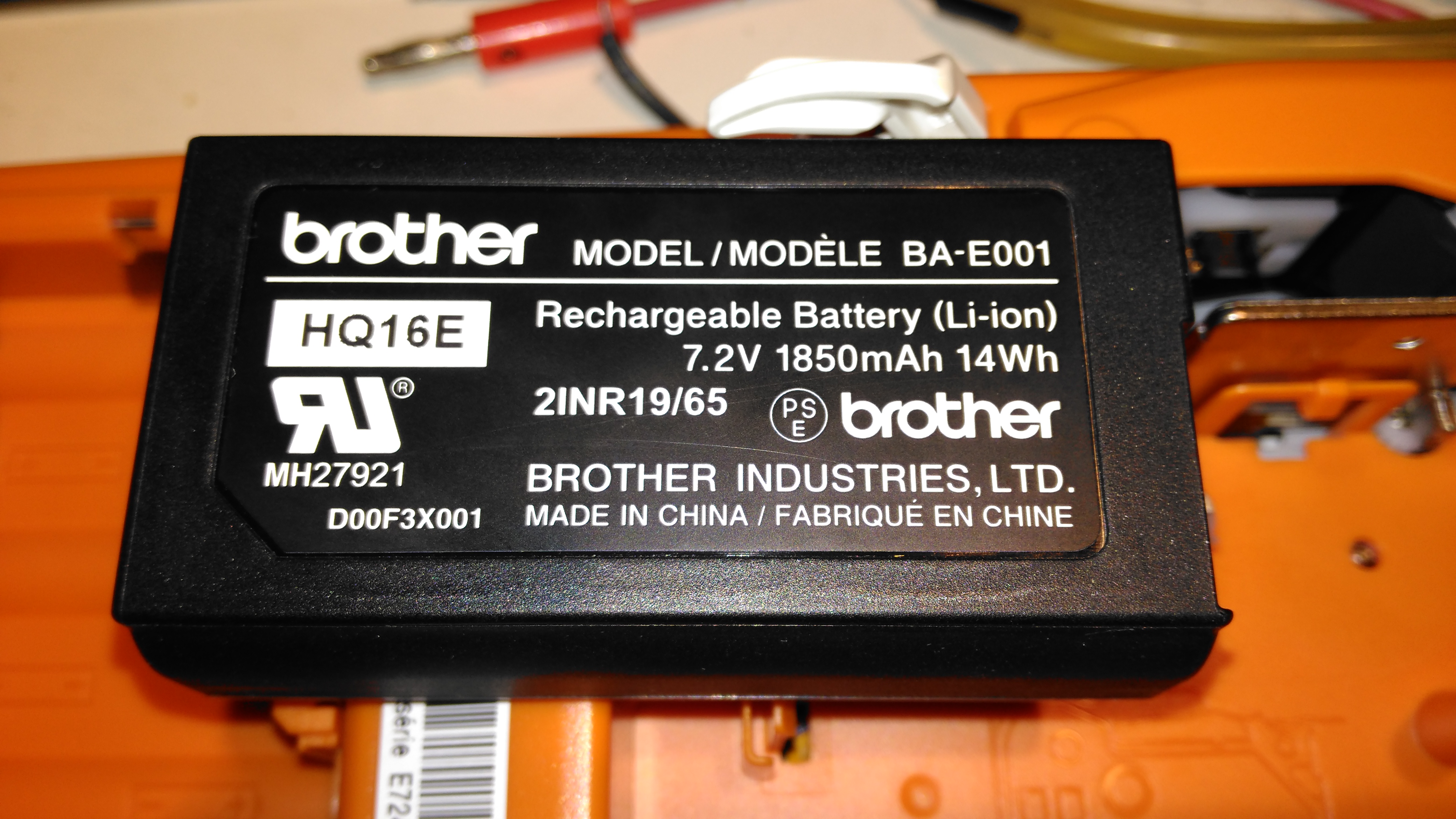
Battery Specs
Pretty standard fare for a 2-cell lithium pack. The charging circuitry doesn’t appear to charge it to full voltage though, most likely to get the most life from the pack.
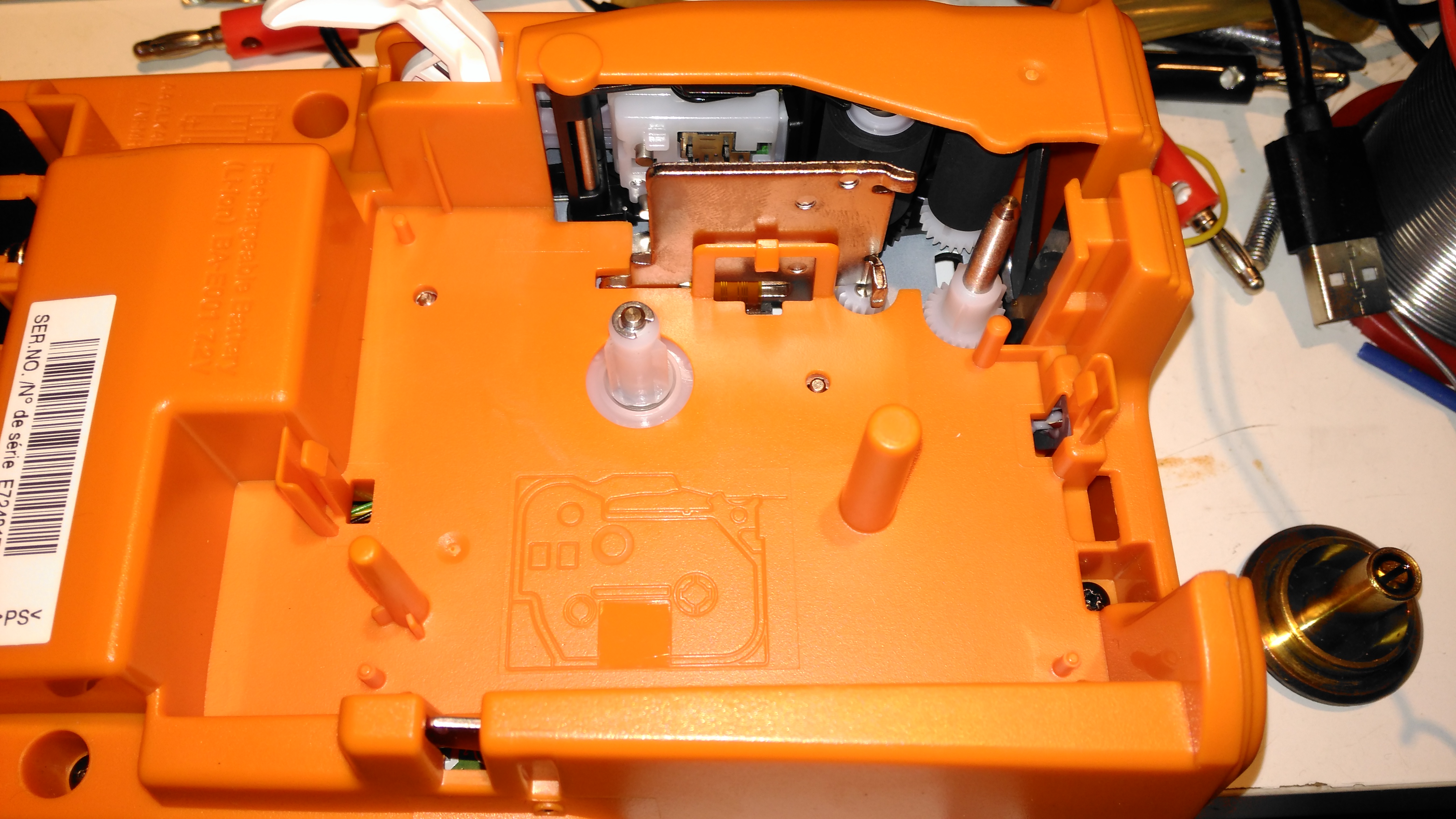
Cartridge Slot
With the cartridge removed, the printer components can be seen. As these cartridges have in effect two rolls, one fro the ribbon & one for the actual label, there are two drive points.
Pinch Rollers & Print Head
The thermal print head is hidden on the other side of the steel heatsink, while the pinch rollers are on the top right. The plastic piece above the print head heatsink has a matrix of switches that engage with holes in the top of the label cartridge, this is how the machine knows what size of ribbon is fitted.
Mainboard
Most of the internal space is taken up by the main board, with the microprocessor & it’s program flash ROM top & centre.
Charger Input
The charger input is located on the keyboard PCB just under the mainboard, which is centre negative, as opposed to 99% of other devices using centre positive, the bastards.
LCD Module
The dot-matrix LCD is attached to the mainboard with a short flex cable, and from the few connections, this is probably SPI or I²C.
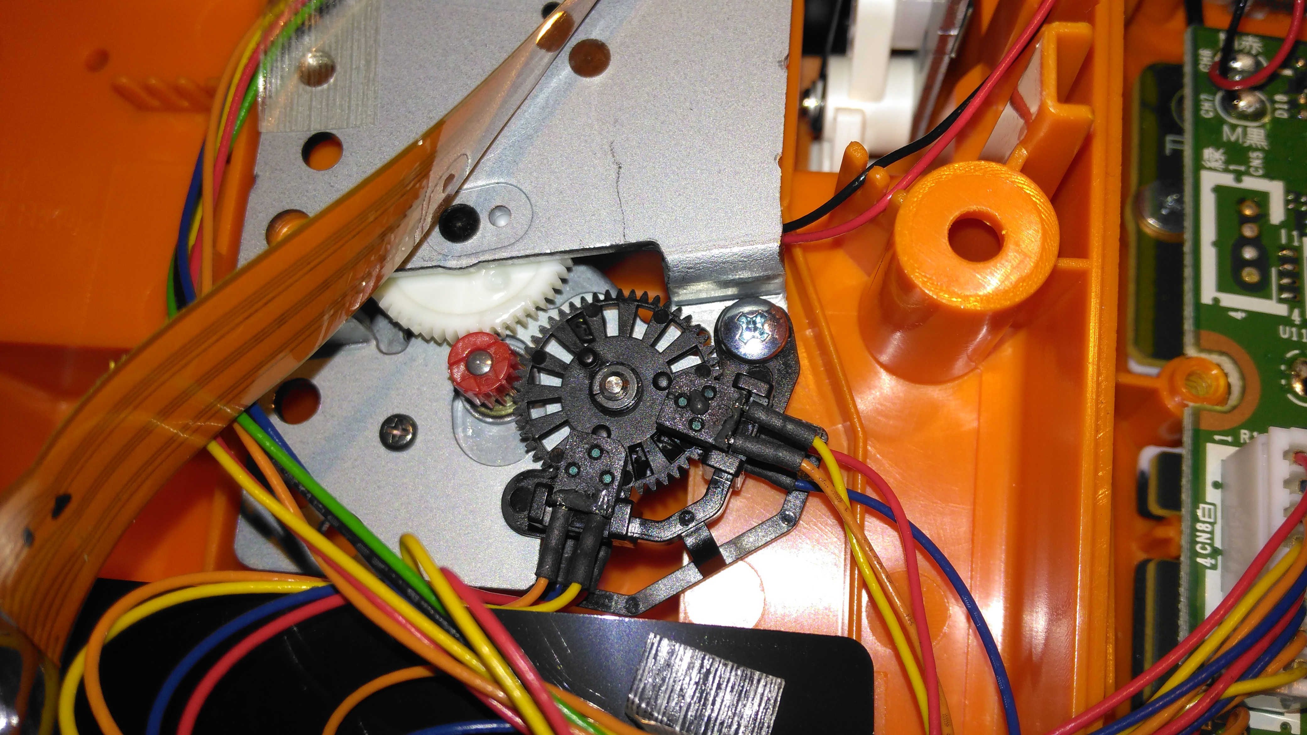
Print Mech Drive
The printer itself is driven by a simple DC motor, speed is regulated by a pair of photo-interrupters forming an encoder on the second gear in the train.
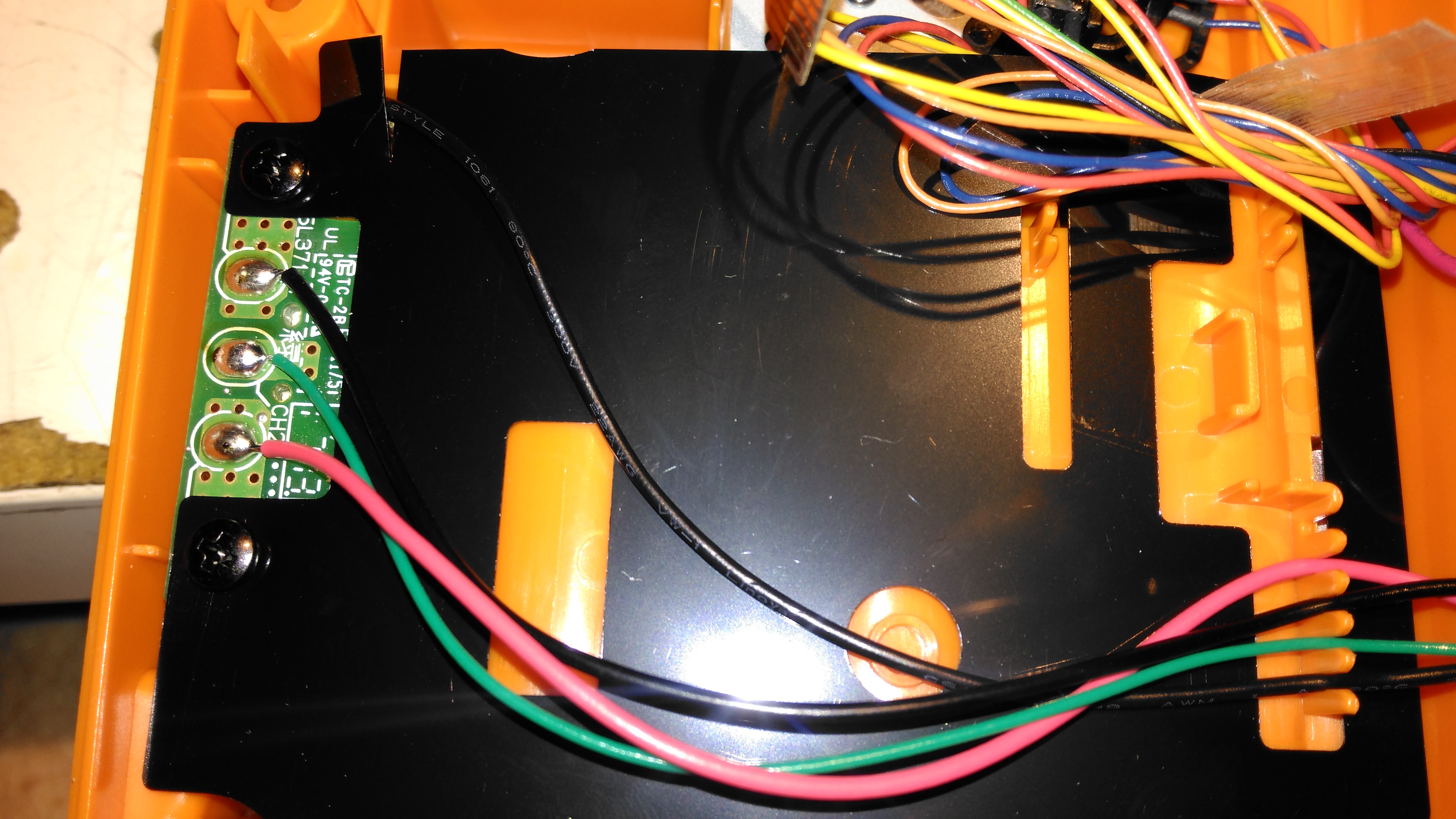
Battery Holder Connections
The back case has the battery connections for both the lithium pack & the AA cells, the lithium pack has a 3rd connection, probably for temperature sensing.
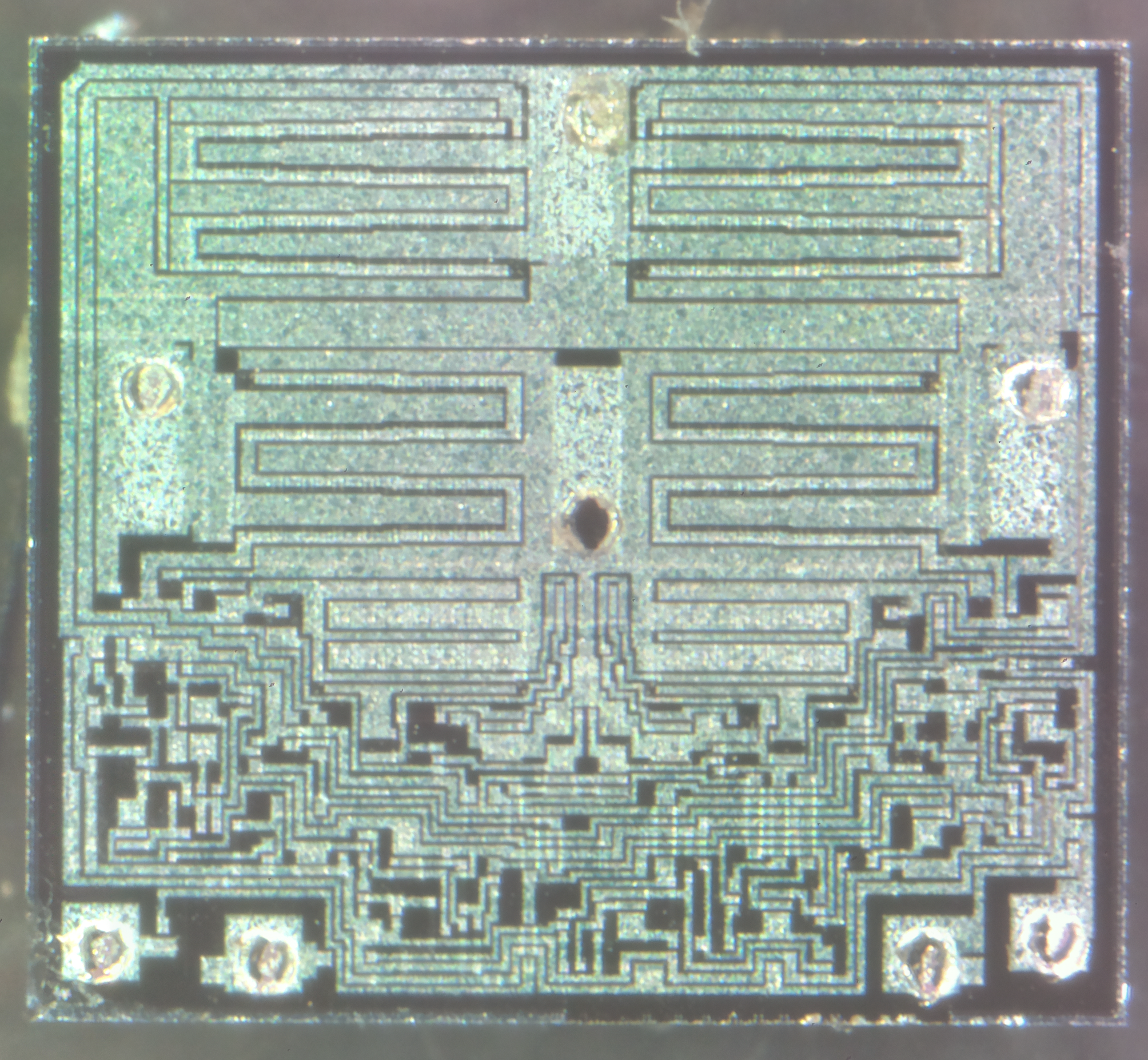
Here’s a jellybean chip – a DC motor driver. This device has all the logic to drive a small motor, such as that used to drive the tray of a CD drive in both directions. The control logic is at the bottom of the die, while the main power transistors are at the top, in H-Bridge formation.
Magnetic tape is the medium of choice for my offline backups & archives, as it’s got an amazing level of durability when in storage. (LTO Has a 30 year archival rating).
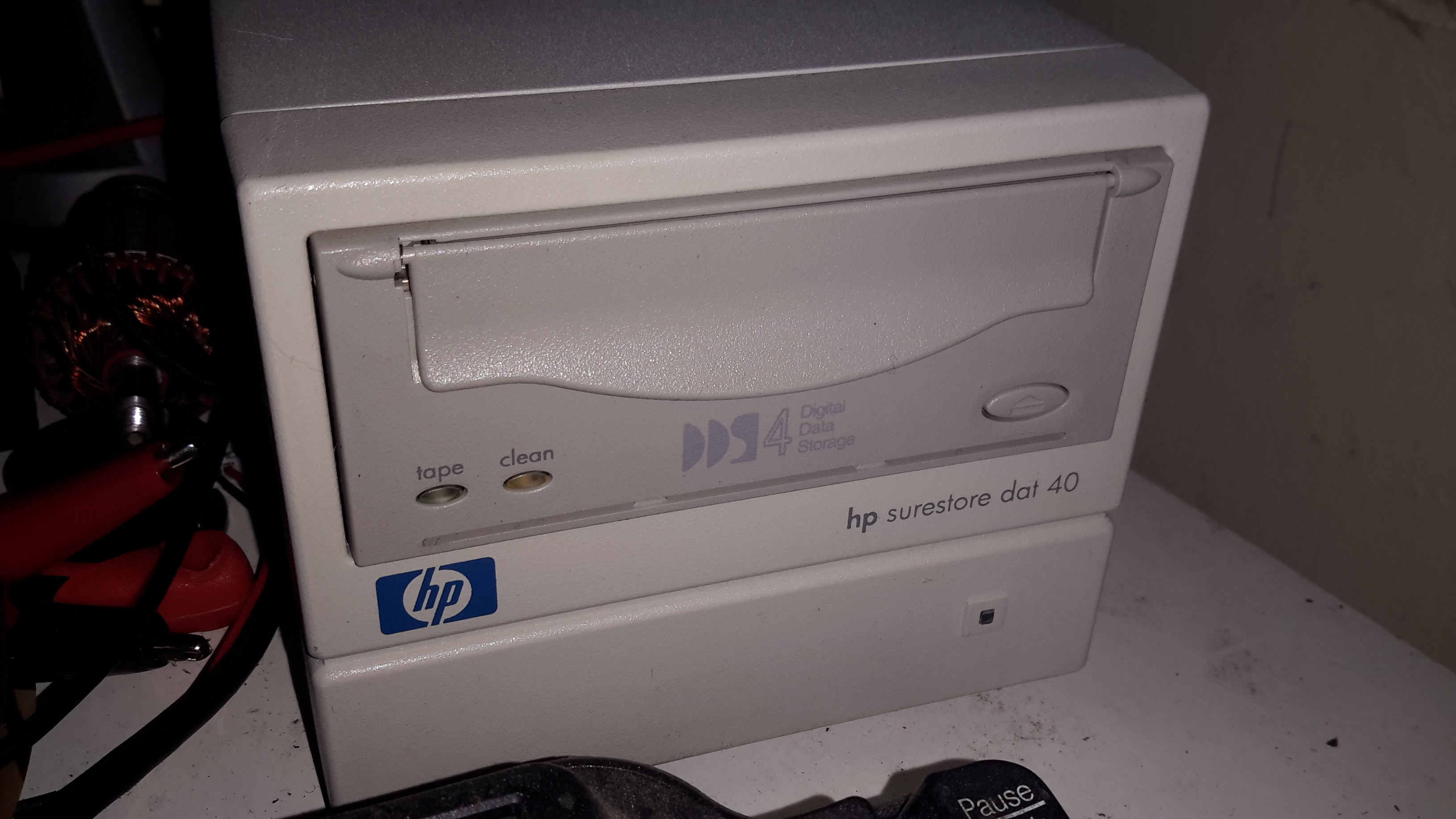
For the smaller stuff, like backing up the web server this very site runs on, another format seemed to suit better. Above is a HP DDS4 tape drive, which will store up to 40GB on a cassette compressed.
I picked this format since I already had some tapes, so it made sense.
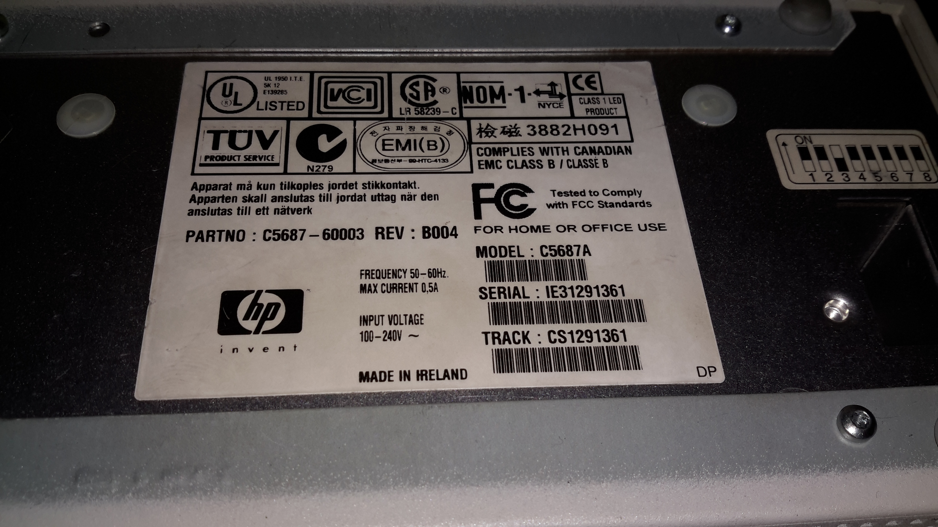
Data Plate
Here’s the info for those who want to know. It’s an older generation drive, mainly since the current generation of tape backup drives are hideously expensive, while the older ones are cheap & plentiful. Unfortunately the older generation of drives are all parallel SCSI, which can be a expensive & awkward to set up. Luckily I already have other parallel SCSI devices, so the support infrastructure for this drive was already in place.
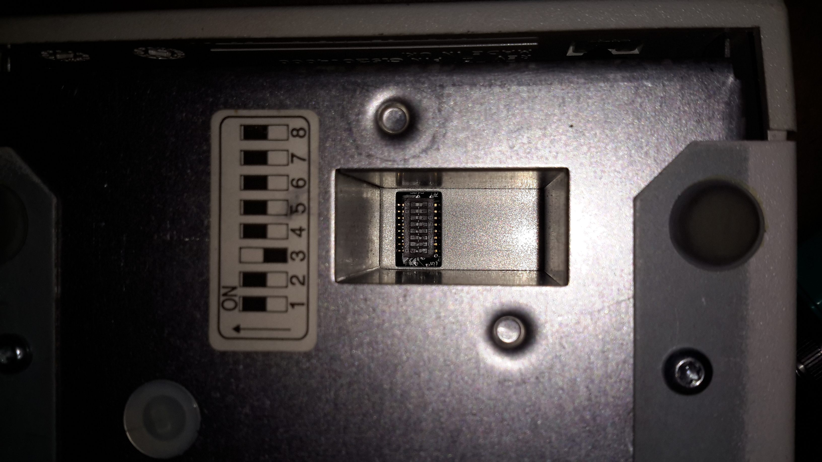
Option Switches
On the bottom of the drive is a bank of DIP switches, according to the manual these are for setting the drive for various flavours of UNIX operating systems. However it doesn’t go into what they actually change.
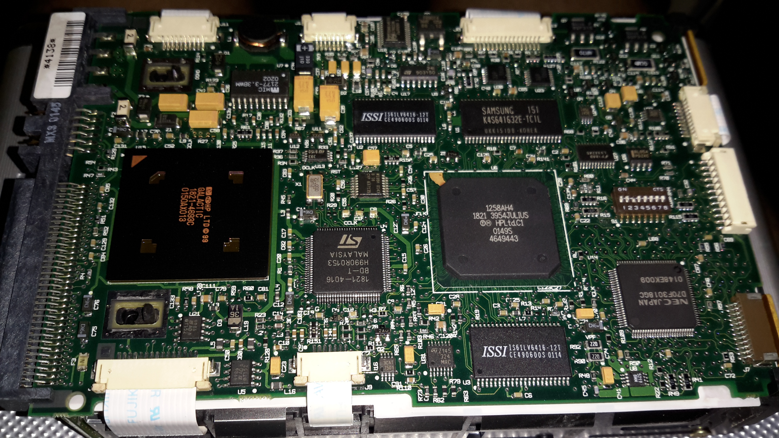
Controller PCB
The bottom of the drive has the control PCB. The large IC on the left is the SCSI interface, I’ve seen this exact same chip on other SCSI tape drives. Centre is a SoC, like so many of these, not much information available.
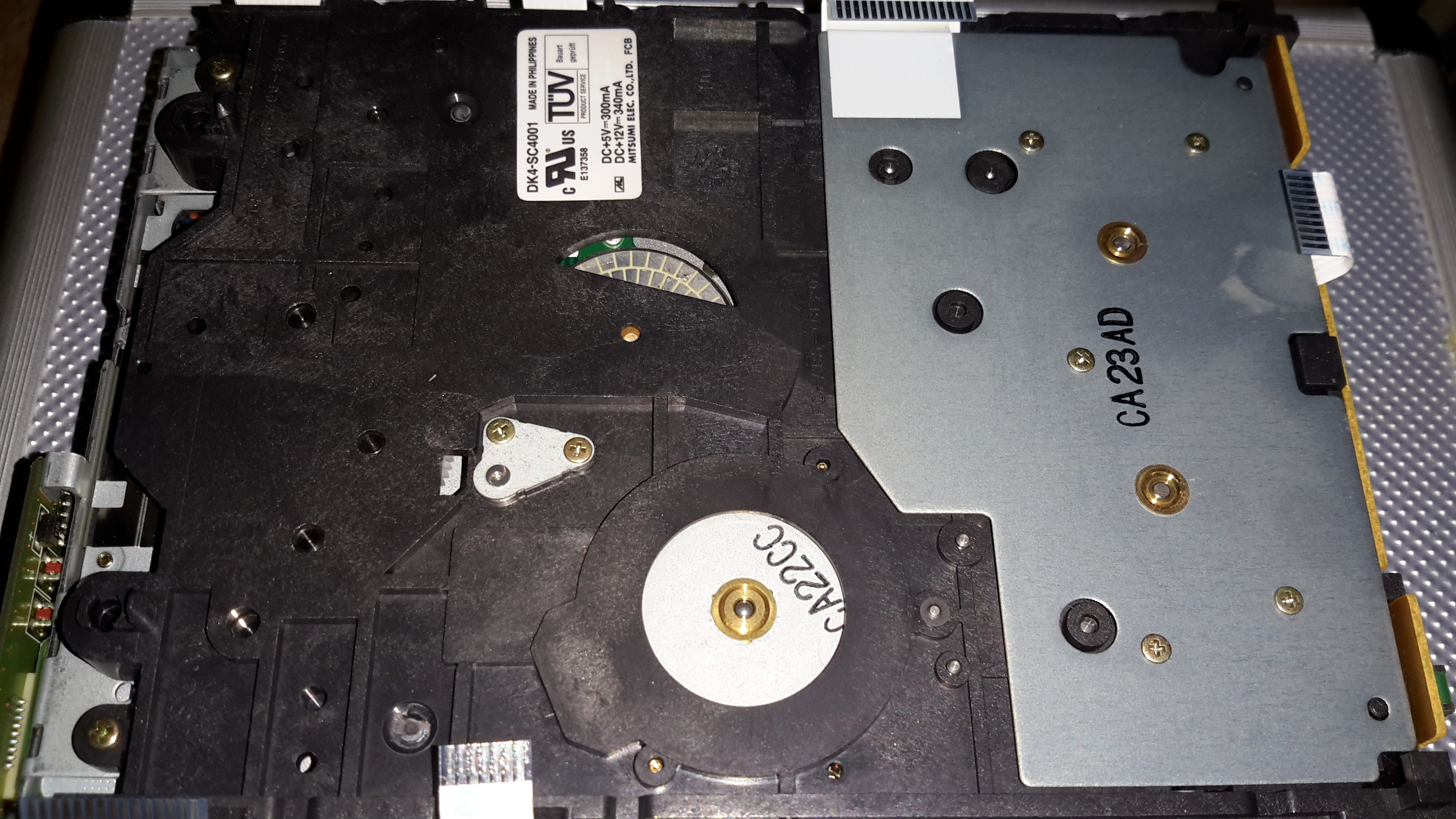
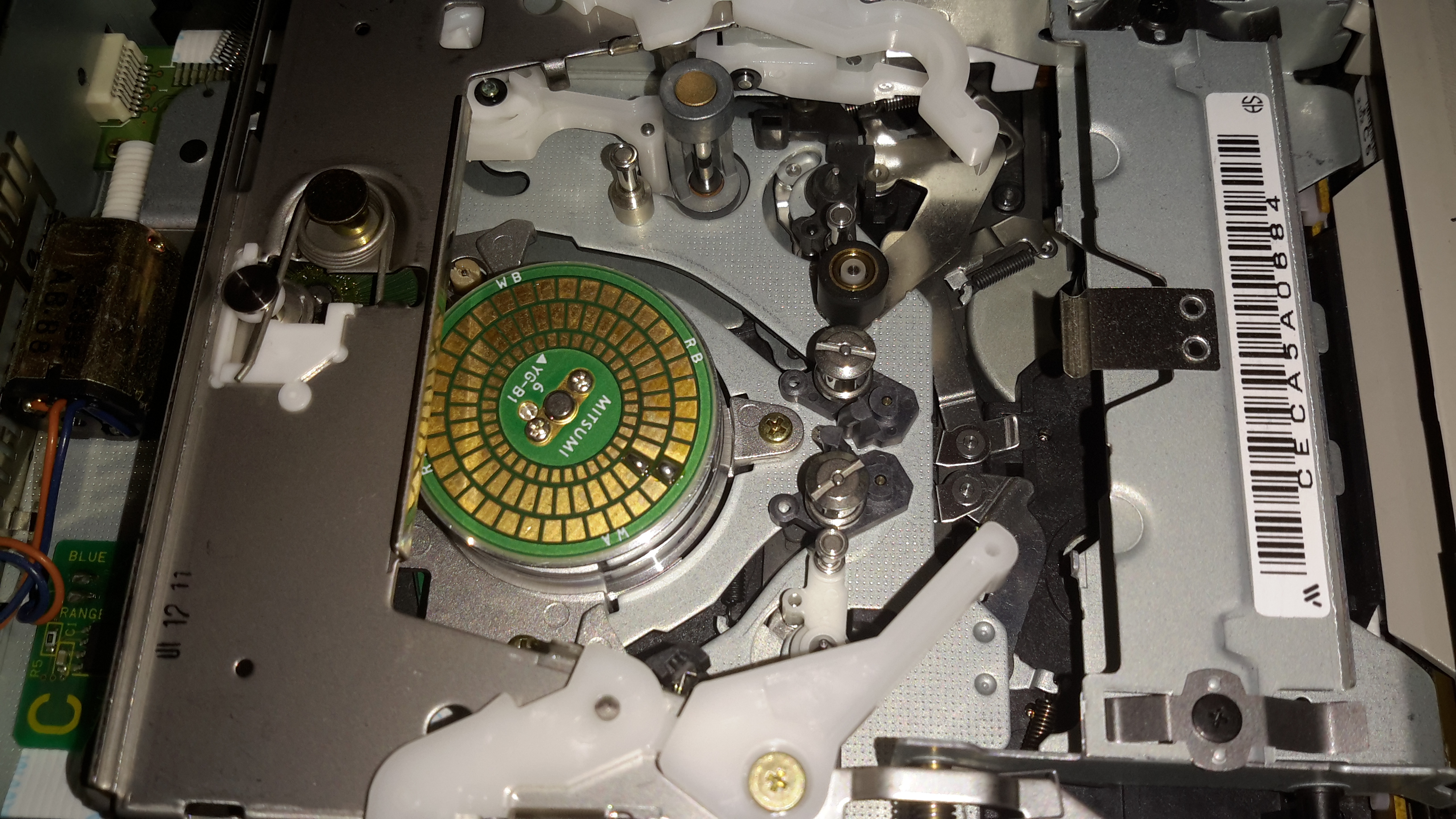
Drive Frame
Removing the board doesn’t reveal much else, just the bottom of the frame with the tape spool motors on the right, capstan motor bottom centre. The bottom of the head drum motor is just peeping through the plastic top centre.
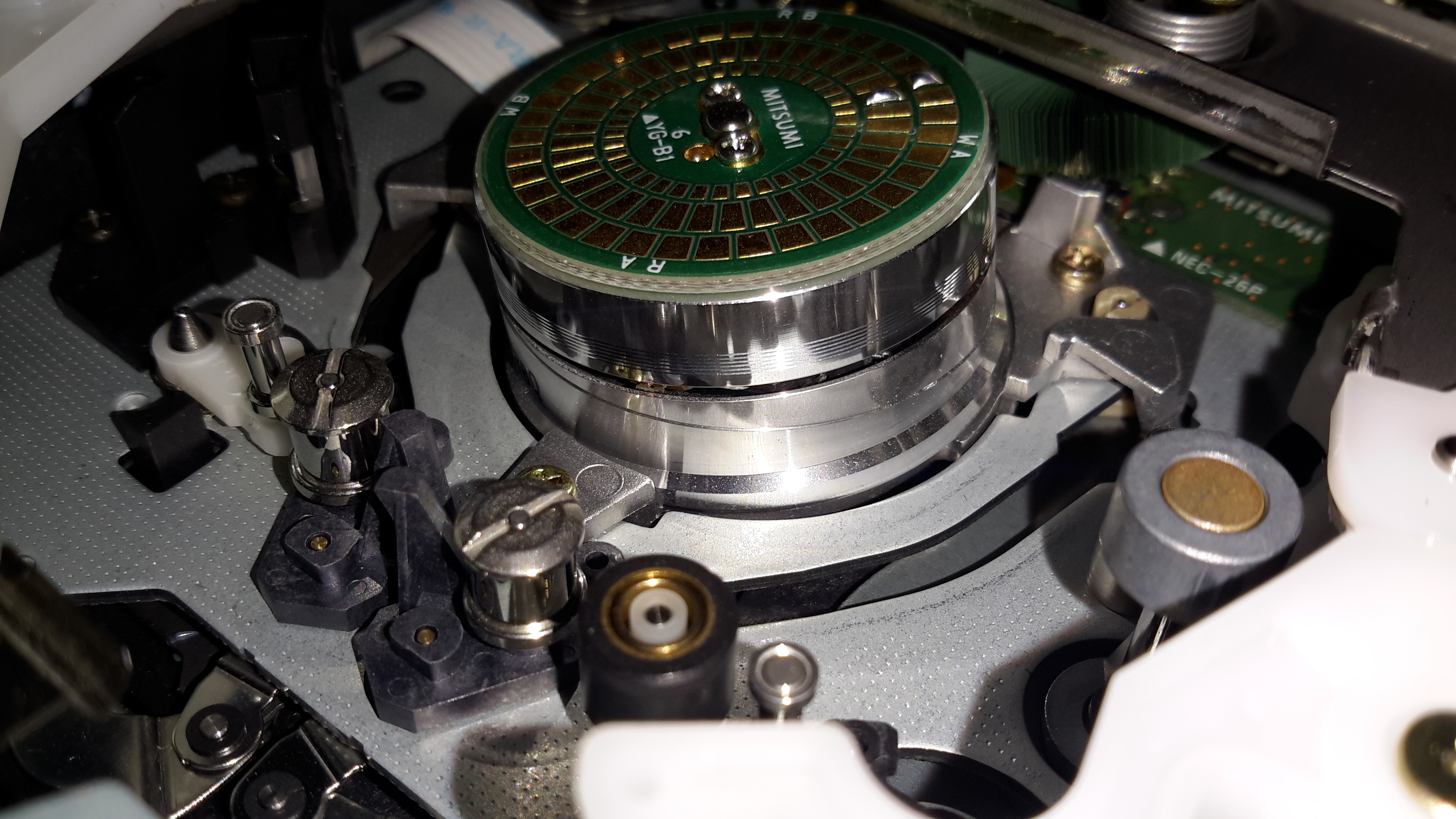
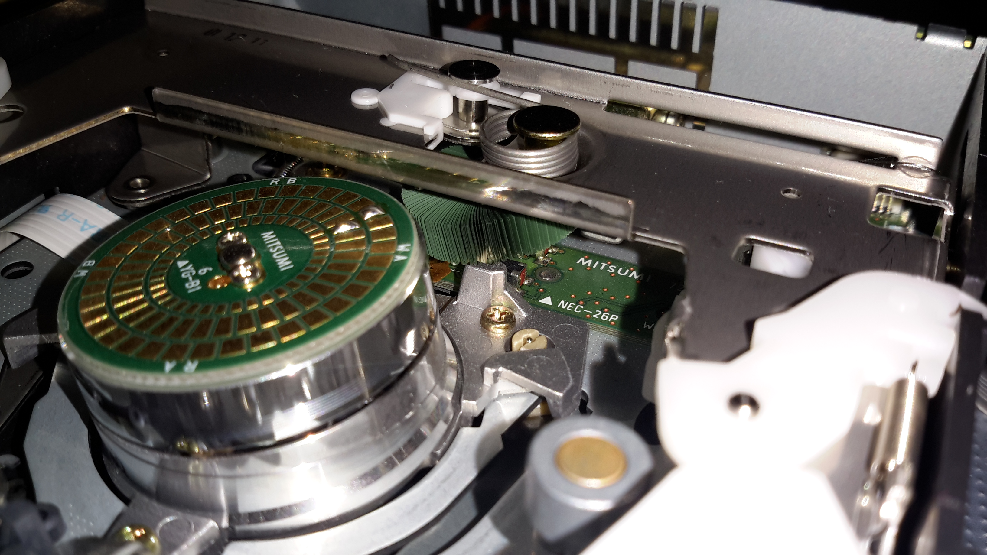
Head Drum
Here’s the head drum itself. These drives use a helical-scan flying head system, like old VHS tape decks. The top of the capstan motor is on the bottom right.
Cleaning Brush
Hidden just under the tape transport frame is the head cleaning brush. I’m not sure exactly what this is made of, but it seems to be plastic.
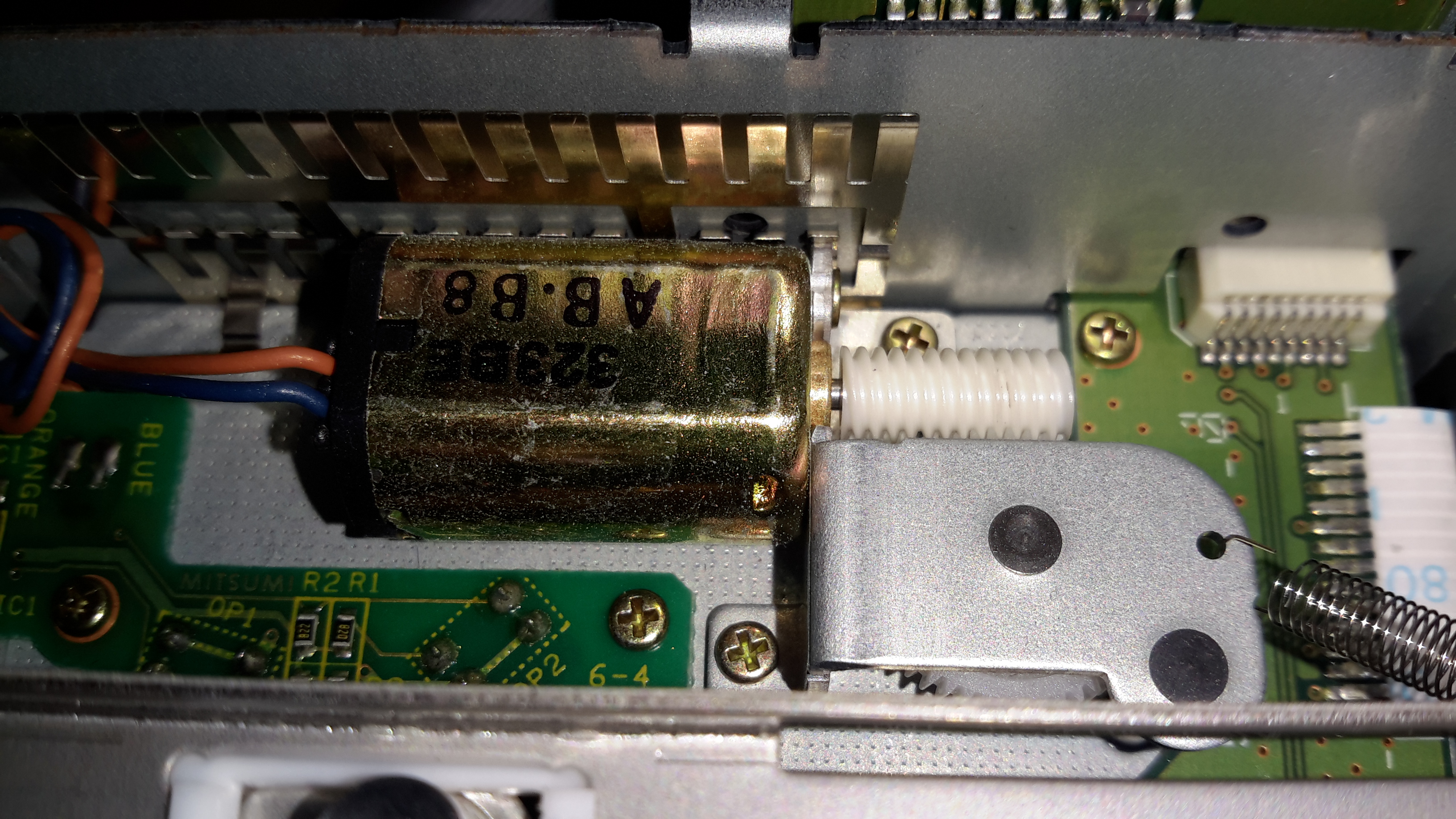
Loading Motor
A single small DC motor with a worm drive handles all tape loading tasks. The PCB to the bottom left of the motor holds several break-beam sensors that tell the drive what position the transport is in.
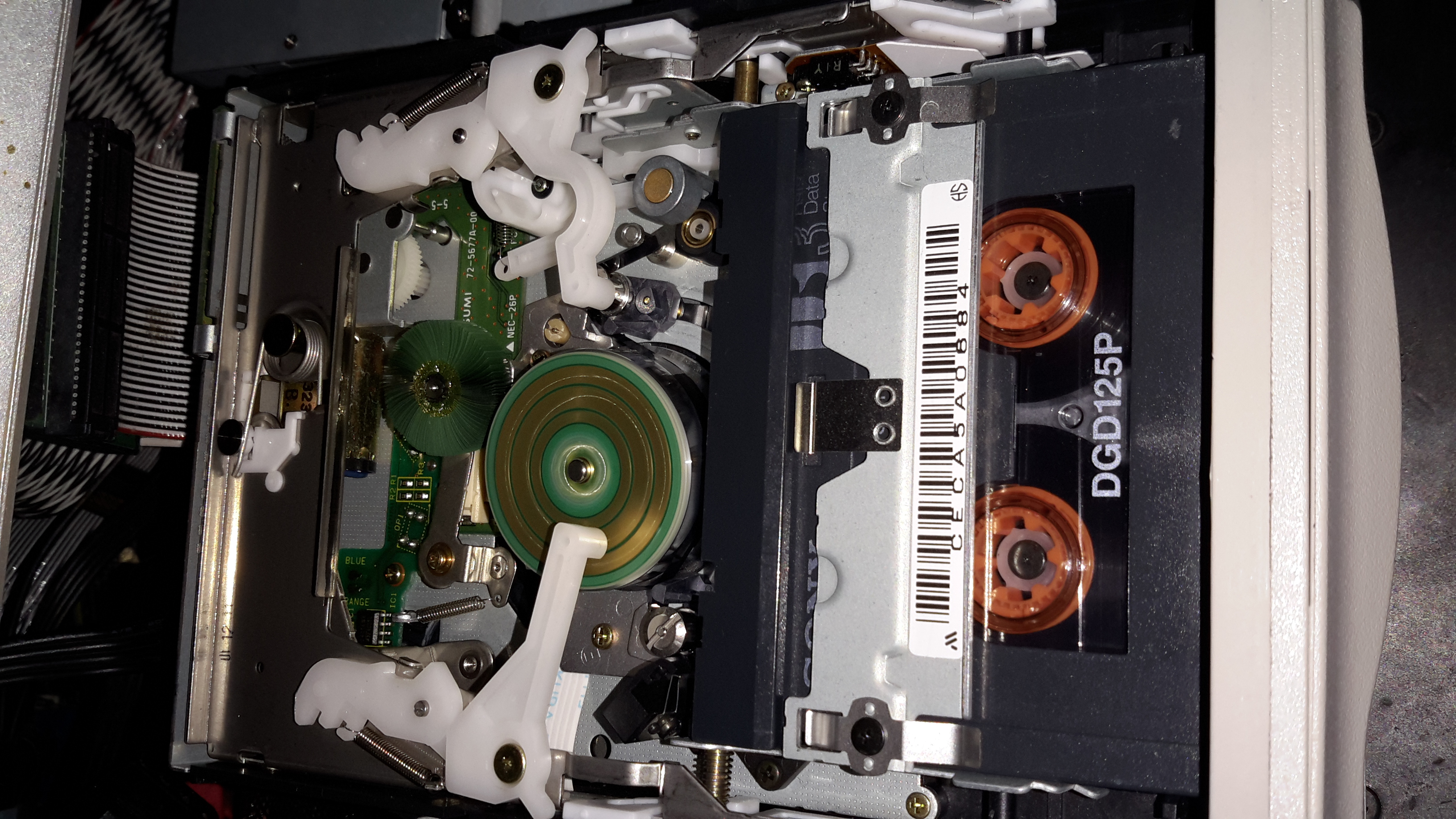
Tape Transport Mech
Here’s the overall tape transport. The PCB on top of the head drum is a novel idea: it’s sole purpose in life is to act as a substrate for solder blobs, used for balancing. As this drum spins at 11,400RPM when a DDS4 tape is in the drive, any slight imbalance would cause destructive vibration.
Tape Transport
Here’s the drive active & writing a tape. (A daily backup of this web server actually). The green head cleaning brush can be better seen here. The drive constantly reads back what it writes to the tape, and if it detects an error, applies this brush momentarily to the drum to clean any shed oxide off the heads. The tape itself is threaded over all the guides, around the drum, then through the capstan & pinch roller.
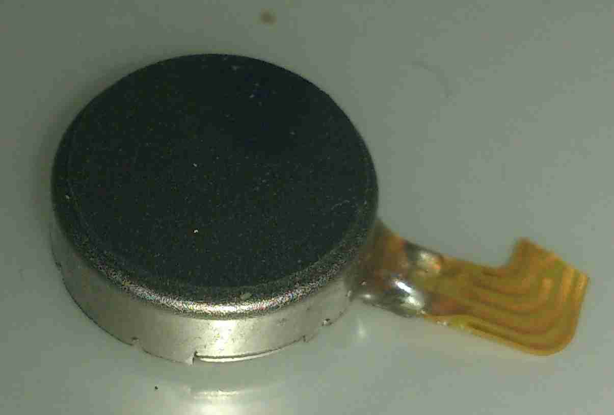
For a while I’ve wondered how these pancake type (AKA “Shaftless”) vibration motors operate, so I figured I’d mutilate one to find out.
Pancake Vibration Motor
These vibrators are found in all kinds of mobile devices as a haptic feedback device, unlike older versions, which were just micro-sized DC motors with an offset weight attached to the shaft, these don’t have any visible moving parts.
Cover Removed
These devices are crimped together, so some gentle attack with a pair of snips was required to get the top cover off.
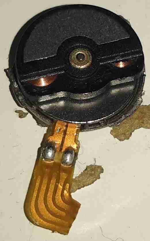
It turns out these are still a standard rotary DC motor, in this case specifically designed for the purpose. The rotor itself is the offset weight, just visible under the steel half-moon shaped section are the armature coils.
Weighted Rotor
The armature lifts off the centre shaft, the coils can clearly be seen peeking out from under the counterweight.
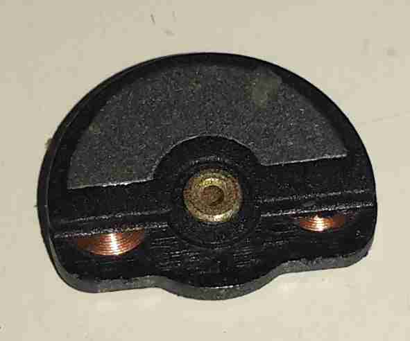
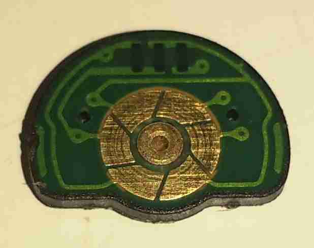
Commutator
The underside of the armature reveals the commutator, which in this device is just etched onto the PCB substrate, the connections to the pair of coils can be seen either side of the commutator segments.
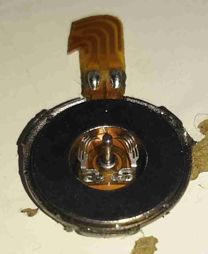
Brushes
The base of the motor holds the brushes in the centre, the outer ring is the stationary permanent magnet. These brushes are absolutely tiny, the whole motor is no more than 6mm in diameter.
Here is an old chemical dosing system for industrial washing machines. These units are 4-pump models, with dual pumpheads. The motors are reversed to operate alternate pumps in the same head.
Label
From 2006, this is a fairly old unit, and made in the UK.
CPU Board
Main controller PCB, with interface to the power electronics via the ribbon cable, an external serial port for programming to it’s left. Powered by an ST microcontroller. The LCD is below this board.
PCU & Driver PCBs
Main power supply, sense input & motor driver boards. The PSU outputs +5v, +12v & +24v. The inputs on the lower left connect to the washing machine & trigger the pumps via the programming on the CPU. The motors are driven by L6202 H-Bridge drivers from ST.
Motor Assembly
Motor & gearbox assembly on the back of the pumphead. These are 24v DC units with 80RPM gearboxes.
UPDATE:
As it seems to be difficult to find, here is the user manual for this unit:
[download id=”5557″]
This is the teardown of a Zebra P330i plastic card printer, used for creating ID cards, membership cards, employee cards, etc. I got this as a faulty unit, which I will detail later on.
This printer supports printing on plastic cards from 1-30mils thick, using dye sublimation & thermal transfer type printing methods. Interfaces supplied are USB & Ethernet. The unit also has the capability to be fitted with a mag stripe encoder & a smart card encoder, for extra cost.
Print Engine
On the left here is the print engine open, the blue cartridge on the right is a cleaning unit, using an adhesive roller to remove any dirt from the incoming card stock.
This is extremely important on a dye sublimation based printing engine as any dirt on the cards will cause printing problems.
Cards In Feeder
Here on the right is the card feeder unit, stocked with cards. This can take up to 100 cards from the factory.
The blue lever on the left is used to set the card thickness being used, to prevent misfeeds. There is a rubber gate in the intake port of the printer which is moved by this lever to stop any more than a single card from being fed into the print engine at any one time.
Card Feeder Belt
Here is the empty card feeder, showing the rubber conveyor belt. This unit was in fact the problem with the printer, the drive belt from the DC motor under this unit was stripped, preventing the cards from feeding into the printer.
Print Head
Here is a closeup of the print head assembly. The brown/black stripe along the edge is the row of thin-film heating elements. This is a 300DPI head.
Print Station
This is under the print head, the black roller on the left is the platen roller, which supports the card during printing. The spool in the center of the picture is the supply spool for the dye ribbon.
In the front of the black bar in the bottom center, is a two-colour sensor, used to locate the ribbon at the start of the Yellow panel to begin printing.
LCD PCB
Inside the top cover is the indicator LCD, the back of which is pictured right.
This is a 16×1 character LCD from Hantronix. This unit has a parallel interface.
LCD
Front of the LCD, this is white characters on a blue background.
Roller Drive Belts
Here is the cover removed from the printer, showing the drive belts powering the drive rollers. There is an identical arrangement on the other side of the print engine running the other rollers at the input side of the engine.
Mains Filter
Here the back panel has been removed from the entire print engine, complete with the mains input wiring & RFI filtering.
This unit has excellent build quality, just what is to be expected from a £1,200+ piece of industrial equipment.
Main Frame With Motors
The bottom of the print engine, with all the main wiring & PCB removed, showing the main drive motors. The left hand geared motor operates the head lift, the centre motor is a stepper, which operates the main transmission for the cards. The right motor drives the ribbon take up spindle through an O-Ring belt.
Feeder Drive Motor
Card feeder drive motor, this connects to the belt assembly through a timing belt identical to the roller drive system.
All these DC geared motors are 18v DC, of varying torque ratings.
Power Supply
Here is the main power supply, a universal input switch-mode unit, outputting 24v DC at 3.3A.
PSU Label
PSU info. This is obviously an off the shelf unit, manufactured by Hitek. Model number FUEA240.
Print Engine Rear
The PSU has been removed from the back of the print engine, here is shown the remaining mechanical systems of the printer.
Print Engine Components
A further closeup of the print engine mechanical bay, the main stepper motor is bottom centre, driving the brass flywheel through another timing belt drive. The O-Ring drive on the right is for the ribbon take up reel, with the final motor driving the plastic cam on the left to raise/lower the print head assembly.
The brass disc at the top is connected through a friction clutch to the ribbon supply reel, which provides tension to keep it taut. The slots in the disc are to sense the speed of the ribbon during printing, which allows the printer to tell if there is no ribbon present or if it has broken.
RFID PCB
Here is a further closeup, showing the RFID PCB behind the main transmission. This allows the printer to identify the ribbon fitted as a colour or monochrome.
The antenna is under the brass interrupter disc on the left.
I/O Daughterboard
The I/O daughterboard connects to the main CPU board & interfaces all the motors & sensors in the printer.
Main PCB
Here is the main CPU board, which contains all the logic & processing power in the printer.
CPU
Main CPU. This is a Freescale Semiconductor part, model number MCF5206FT33A, a ColdFire based 32-bit CPU. Also the system ROM & RAM can be seen on the right hand side of this picture.
Ethernet Interface
Bottom of the Ethernet interface card, this clearly has it’s own RAM, ROM & FPGA. This is due to this component being a full Parallel interface print server.
Ethernet Interface Top
Top of the PCB, showing the main processor of the print server. This has a ferrite sheet glued to the top, for interference protection.
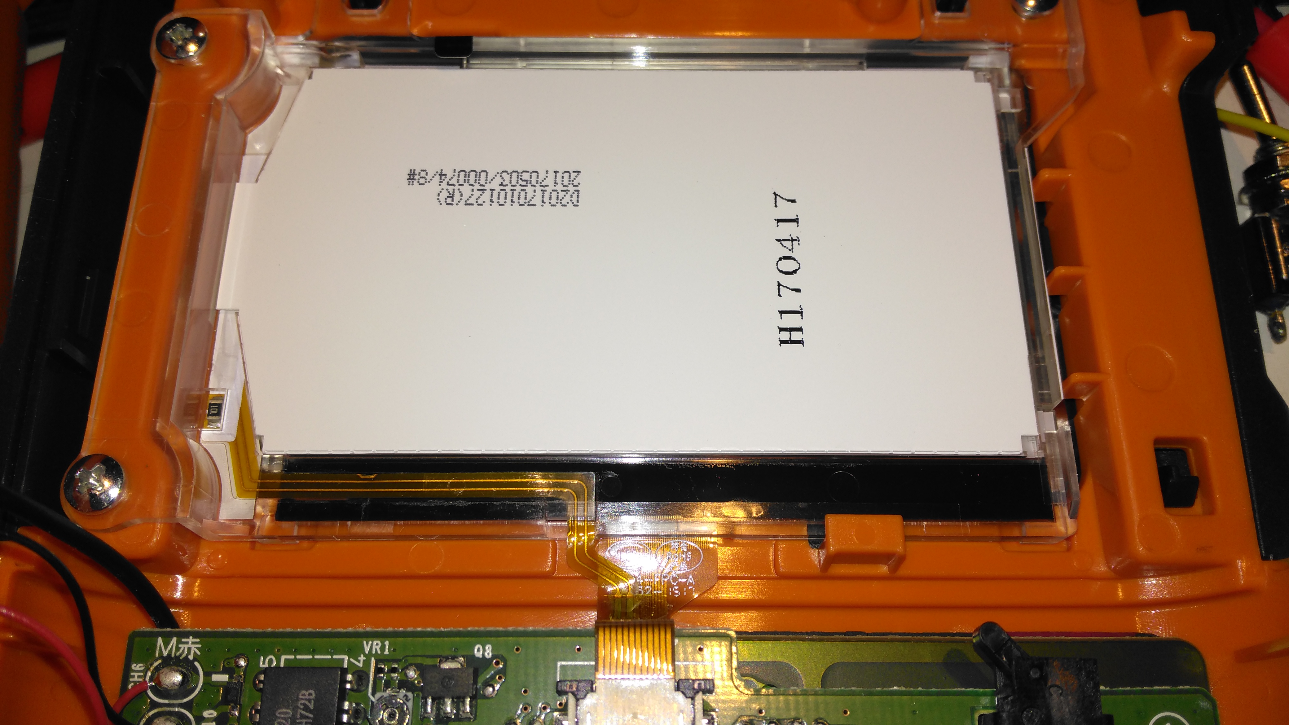
Here is a label maker, bought on offer at Maplin Electronics. Full Qwerty keyboard with 1 line dot matrix LCD display visible here. Power is 4 AAA cells or a 6v DC Adaptor.
Rear
Rear cover removed. Battery compartment is on the left hand side, space for the tape cartridge on the right. Ribbon cable leading to the thermal print head is on the far right, with rubber tape drive roller.
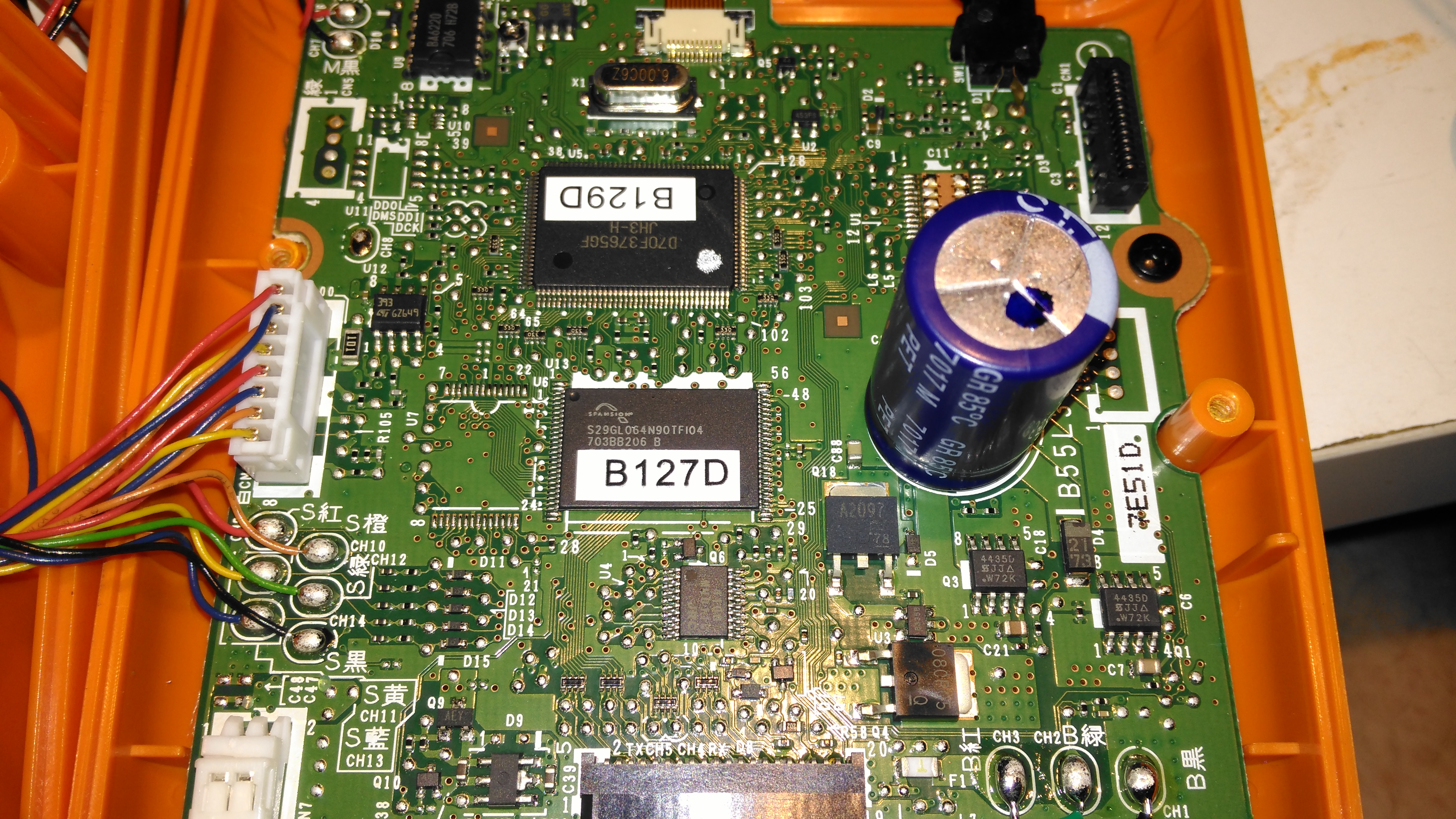
PCB
PCB under the top cover with the main CPU, a MN101C77CBM from Panasonic. This CPU features 48K Mask ROM & 3K of RAM. Max clock frequency is 20MHz. 32kHz clock crystal visible underneath a Rohm BA6220 Electronic speed controller IC.
This is used to drive the printer motor at a constant accurate speed, to feed the tape past the thermal head. Miniature potentiometer adjusts speed.
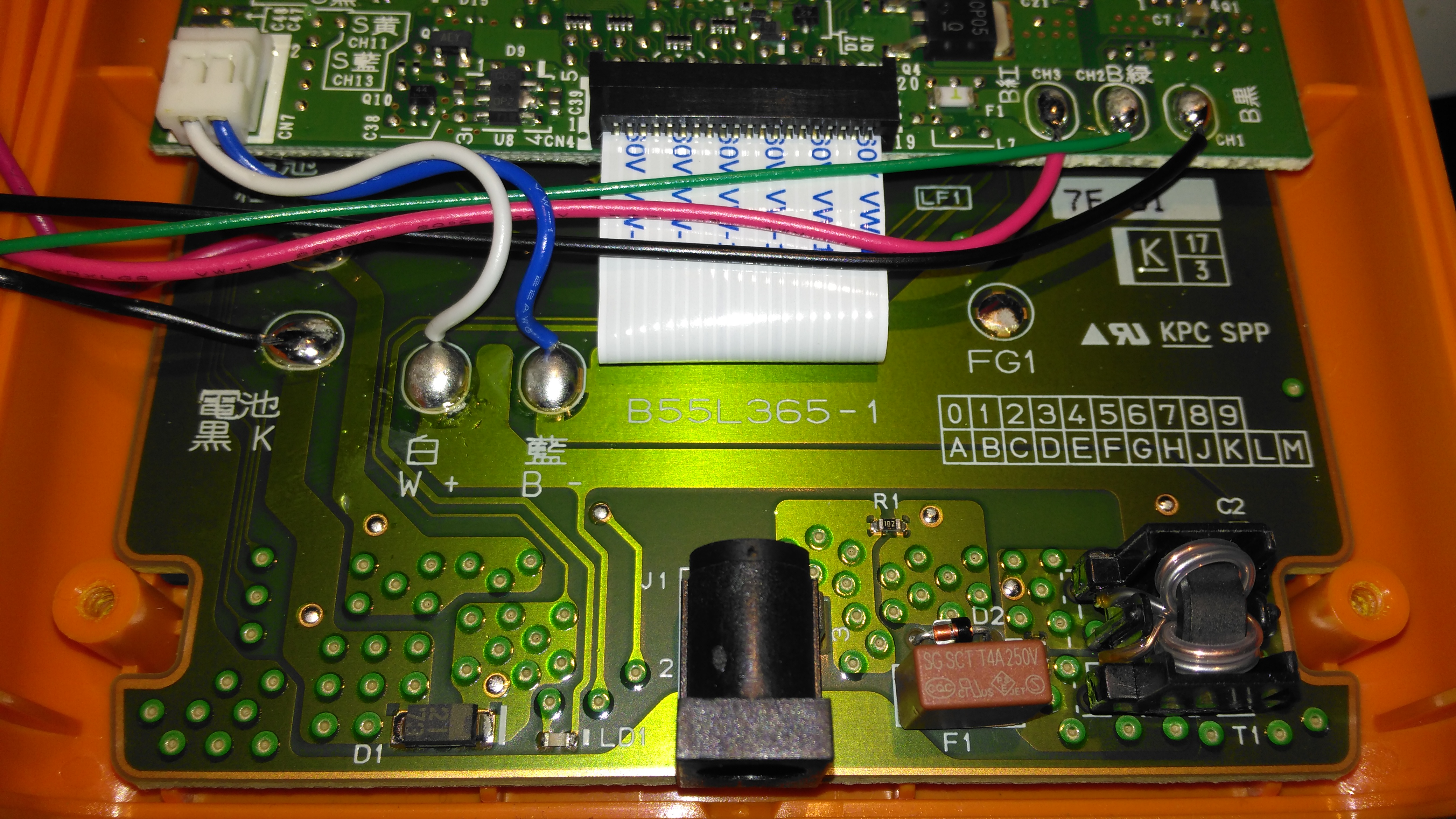
Ribbon cable at the bottom of the board connects to the print head, various wiring at the left connects to the battery & DC Jack.
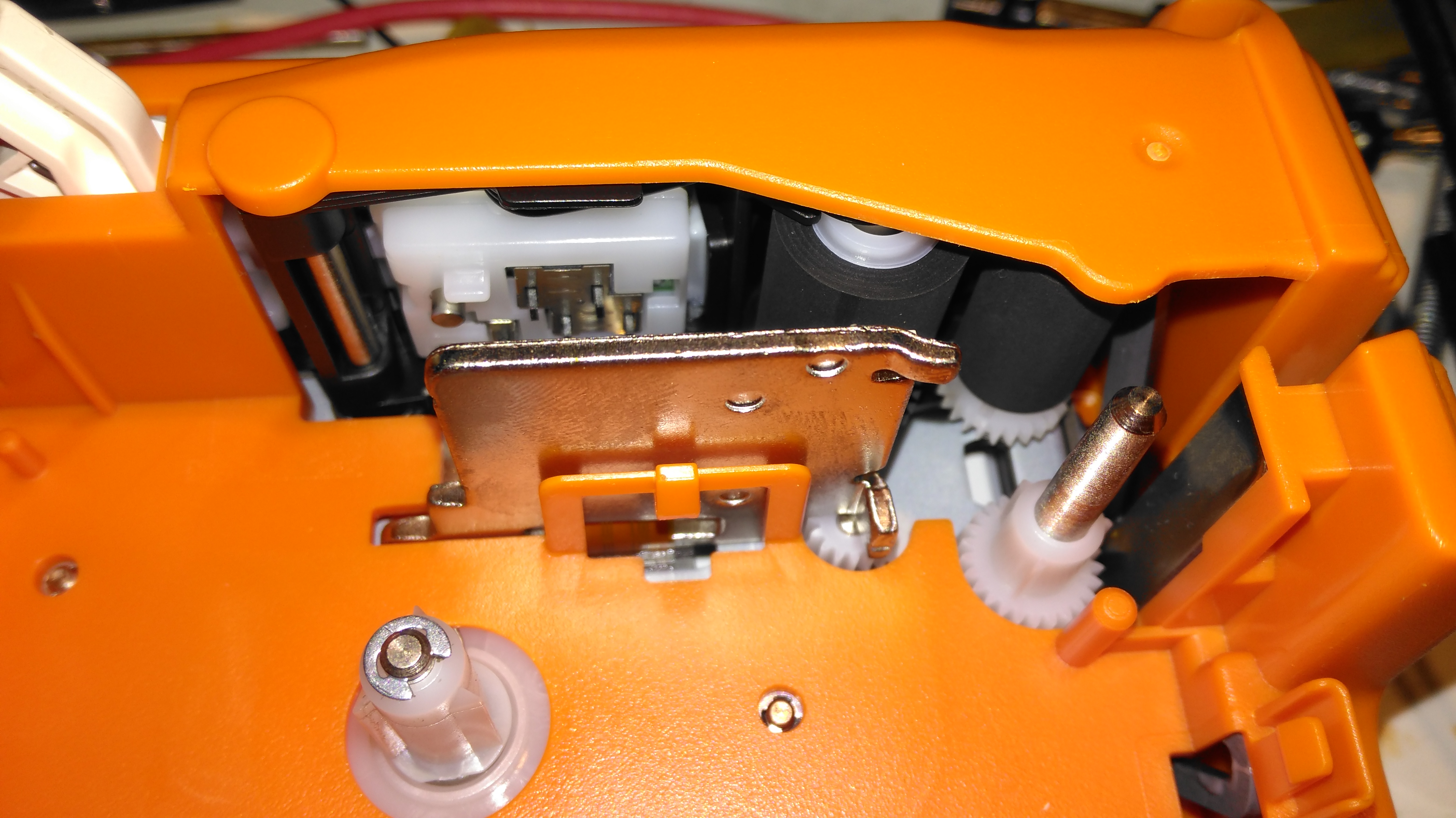
Printer Drive
Printer drive mechanism. Small DC motor drives the pinch roller though a gear train. DC Jack & reverse polarity protection diode is on the right.
This unit uses a centre negative DC jack, which is unusual.
Cartridge
Thermal tape cartridge, black text on white background.
Here is a Sanyo tape recorder, with built in voice activation. Takes standard audio cassettes.
Here visible is the speaker on the left, microphone is on the right of the tape window. The tape counter is at the top.
Back Removed
Back cover removed from the unit, showing the PCB & the connections. The IC is the controller/amplifier.
PCB
Top of the PCB, control switches, volume potentiometer & microphone/headphone sockets on the right. DC power jack top left. Switch bottom centre senses what mode the tape drive is in.
Tape Deck
Rear of the tape deck, main drive motor is bottom right, driving the capstan through a drive belt. This drives the tape spools through a series of gears & clutches. Belt going to top left drives the tape counter.
Drive
Front of the tape drive. Read/write head is top centre. Blue head is bulk erase head used during recording.
Here is a Bosch 14.4v Professional cordless drill/driver, recovered from a skip!
It was thrown away due to a gearbox fault, which was easy to rectify.
Internals
Here is the drill with the side cover removed, showing it’s internal parts. The speed controller is below the motor & gearbox here. The unit at the top consists of a 12v DC motor, coupled to a 4-stage epicyclic gearbox unit, from which can be selected 2 different ratios, by way of the lever in the centre of the box. This disables one of the gear stages. There is a torque control clutch at the chuck end of the gearbox, this was faulty when found.
Motor
Here is the drive motor disconnected from the gearbox, having a bayonet fitting on the drive end.
Drive Gear
This is the primary drive gear of the motor, which connects with the gearbox.
Cooling Fan
The motor is cooled by this fan inside next to the commutator, drawing air over the windings.
Gearbox
This is the gearbox partially disassembled, showing the 1st & second stages of the geartrain. The second stage provides the 2 different drive ratios by having the annulus slide over the entire gearset, disabling it entirely, in high gear. The annulus gears are a potential weak point in this gearbox, as they are made from plastic, with all other gears being made of steel.
Charger
Here is the charging unit for the Ni-Cd battery packs supplied with the drill. The only indicator is the LED shown here on the front of the unit, which flashes while charging, & comes on solid when charging is complete. Charge termination is by way of temperature monitoring.
Transformer
Here the bottom of the charger has been removed, showing the internal parts. An 18v transformer supplies power to the charger PCB on the left.
Charger PCB
This is the charger PCB, with a ST Microelectronics controller IC marked 6HKB07501758. I cannot find any information about this chip.
Battery Pack Internals
Here is a battery pack with the top removed, showing the cells.
Temperature Sensor
This is the temperature sensor embedded inside the battery pack that is used by the charger to determine when charging is complete.
Tip Jar
If you’ve found my content useful, please consider leaving a donation by clicking the Tip Jar below!
All collected funds go towards new content & the costs of keeping the server online.