A few months ago I did a teardown on this Anker PowerPort Speed 5 USB charger, but I didn’t get round to detailing the conversion to 12v I had to do, so I’ll get to that now I’ve got a couple more to convert over.
Power Module
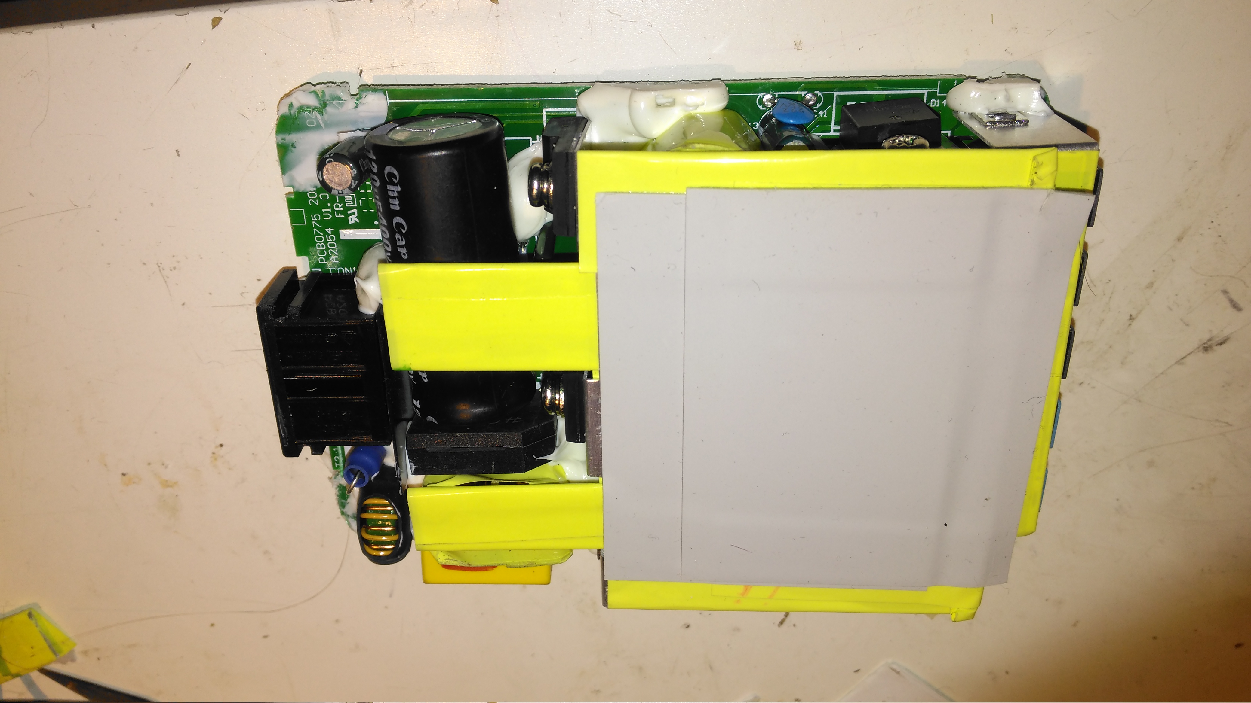
Here’s the internals of the Anker charger once I’ve removed the casing – which like many things these days, is glued together. (Joints can be cracked with a screwdriver handle without damaging the case). There’s lots of heatsinking in here to cool the primary side switching devices & the pot core transformers, so this is the first thing to get removed.
Heatsink Removed
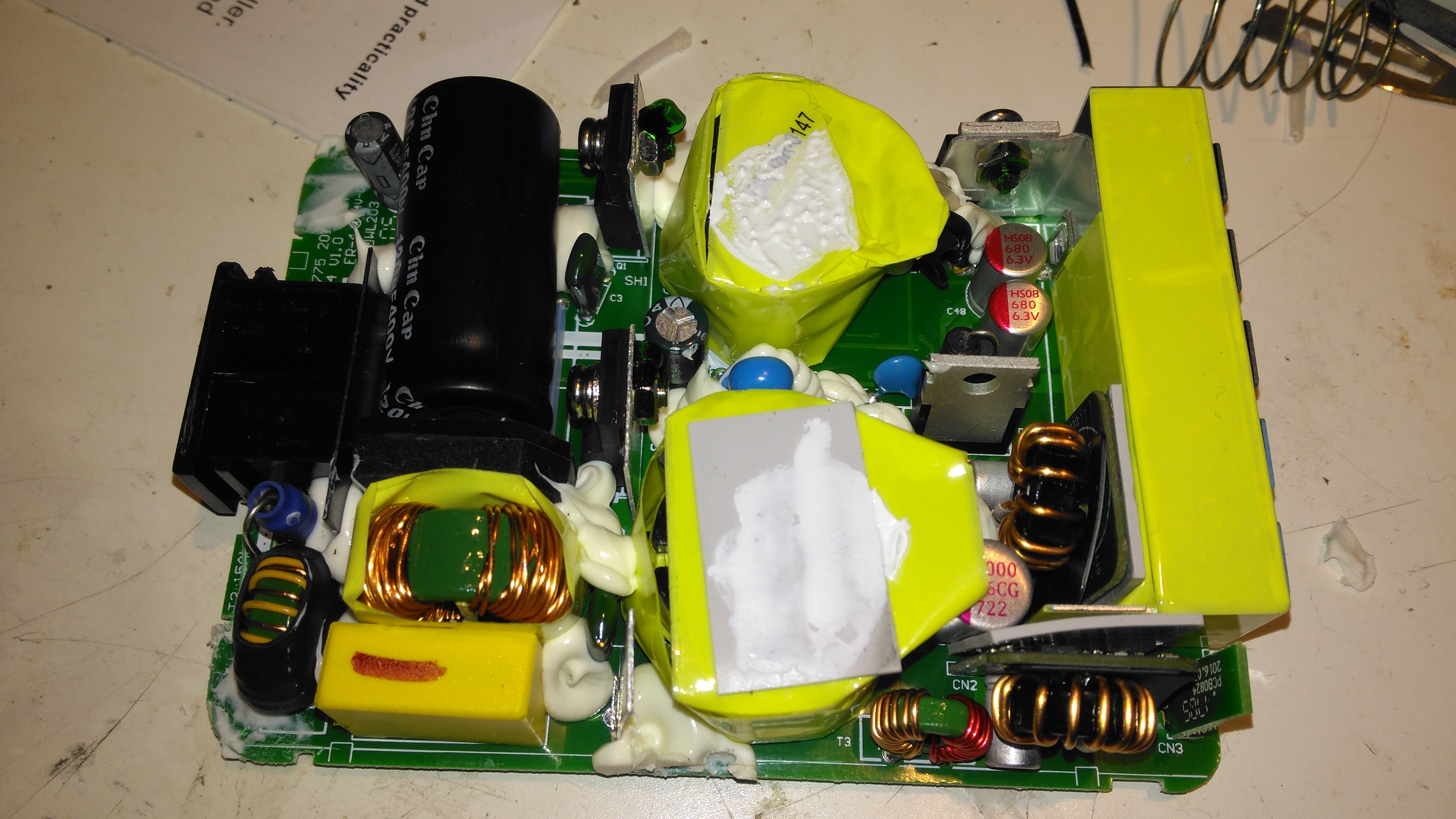
Once the heatsink has been removed, the pot core transformers are visible, wrapped in yellow tape. There’s some more heatsink pads & thermal grease here, to conduct heat better. The transformers, primary side switching components & input filter capacitor have to go.
Primary Side Components Removed
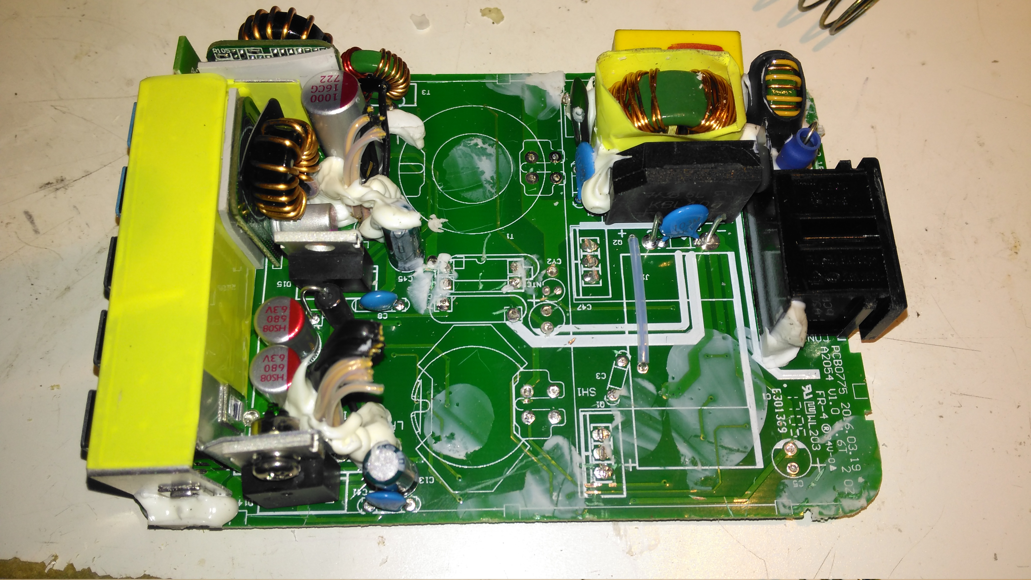
Here’s the PCB once all the now redundant mains conversion components have been deleted. I’ve left the input filtering & bridge rectifier in place, as this solves the issue of the figure-8 cable on the input being reversible, polarity of the input doesn’t matter with the bridge. I’ve removed the main filter capacitor to make enough room for the DC-DC converters to be fitted.
Tails Installed
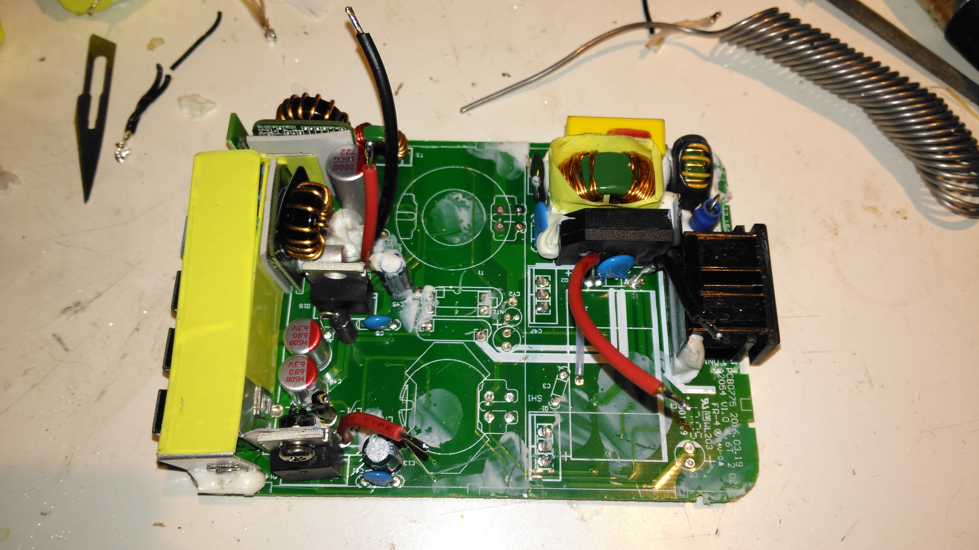
Installing the tails to connect everything together is the next step, this charger requires two power supplies – the QC3 circuits need 14.4v to supply the multi-voltage modules, the remaining 3 standard ports require 5v. The DC input tails are soldered into place where the main filter capacitor was, while the outputs are fitted to the spot the transformer secondary windings ended up. I’ve left the factory Schottky rectifiers in place on the secondary side to make things a little more simple, the output voltages of both the DC-DC converters does need to be increased slightly to compensate for the diode drops though. I’ve also bypassed the mains input fuse, as at 12v the input current is going to be substantially higher than when used on mains voltage.
DC-DC Converters Installed
With a squeeze both the boost converter & the buck converter fit into place on the PCB.
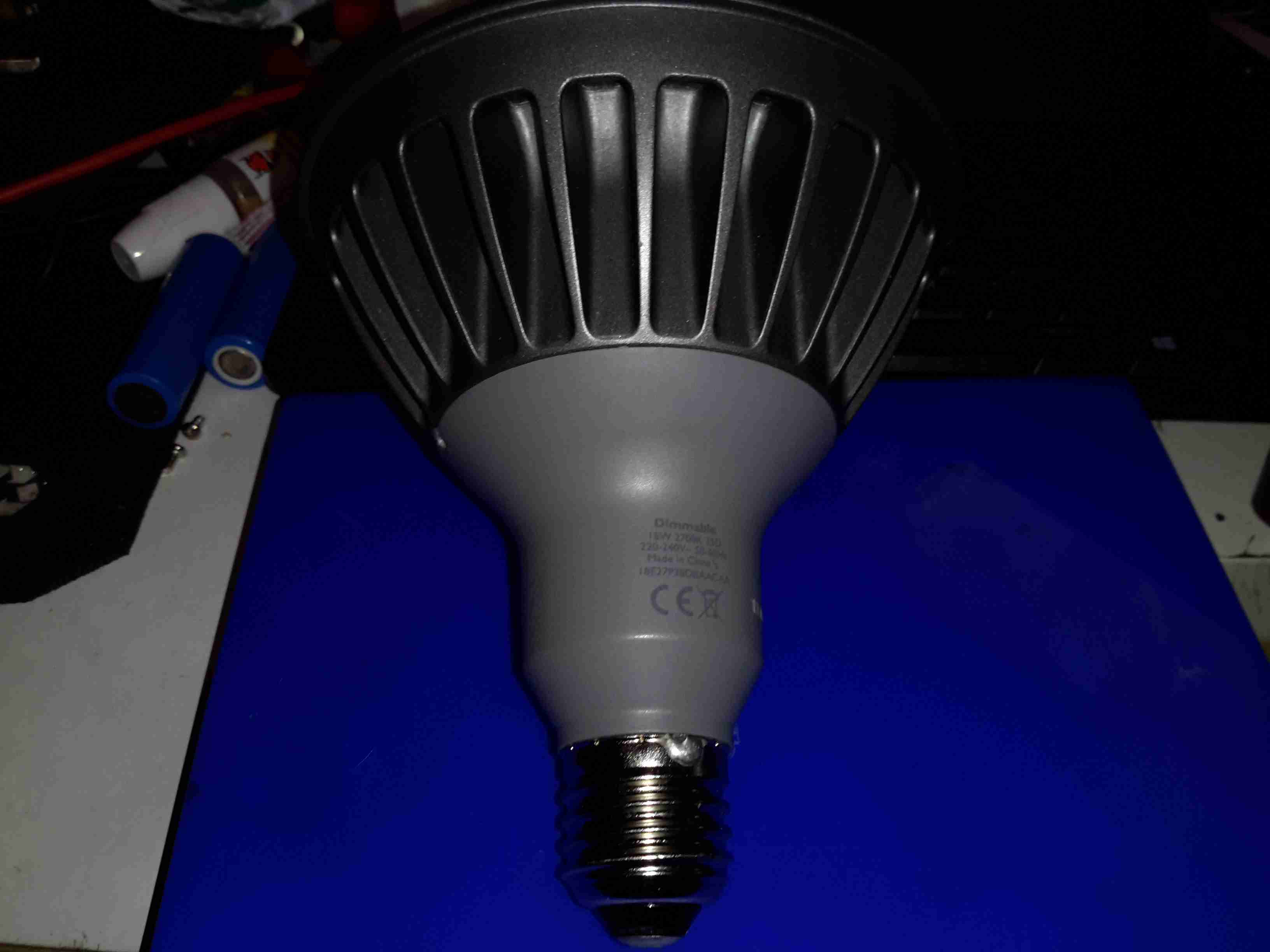
These large LED Philips PAR38 lamps were recently on clearance sale in my local T.N. Robinsons electrical contractors for about £3, so I decided to grab one in the hopes I might be able to hack it into a low-voltage LED lamp. These are full-size PAR38 format, with most of the bulk being the large aluminium heatsink on the front. The back section with the power supply module is secured with silicone, so some unreasonable force was required to liberate the two pieces.
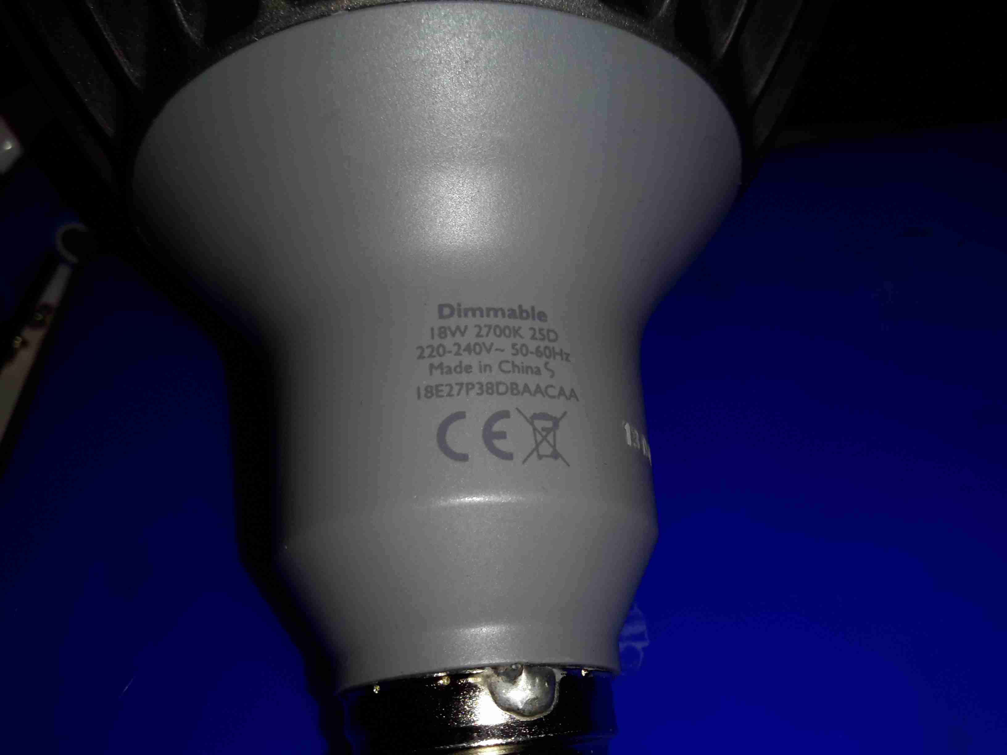
Specification
These lamps are rated at 18W in operation, and are surprisingly bright for this power level.
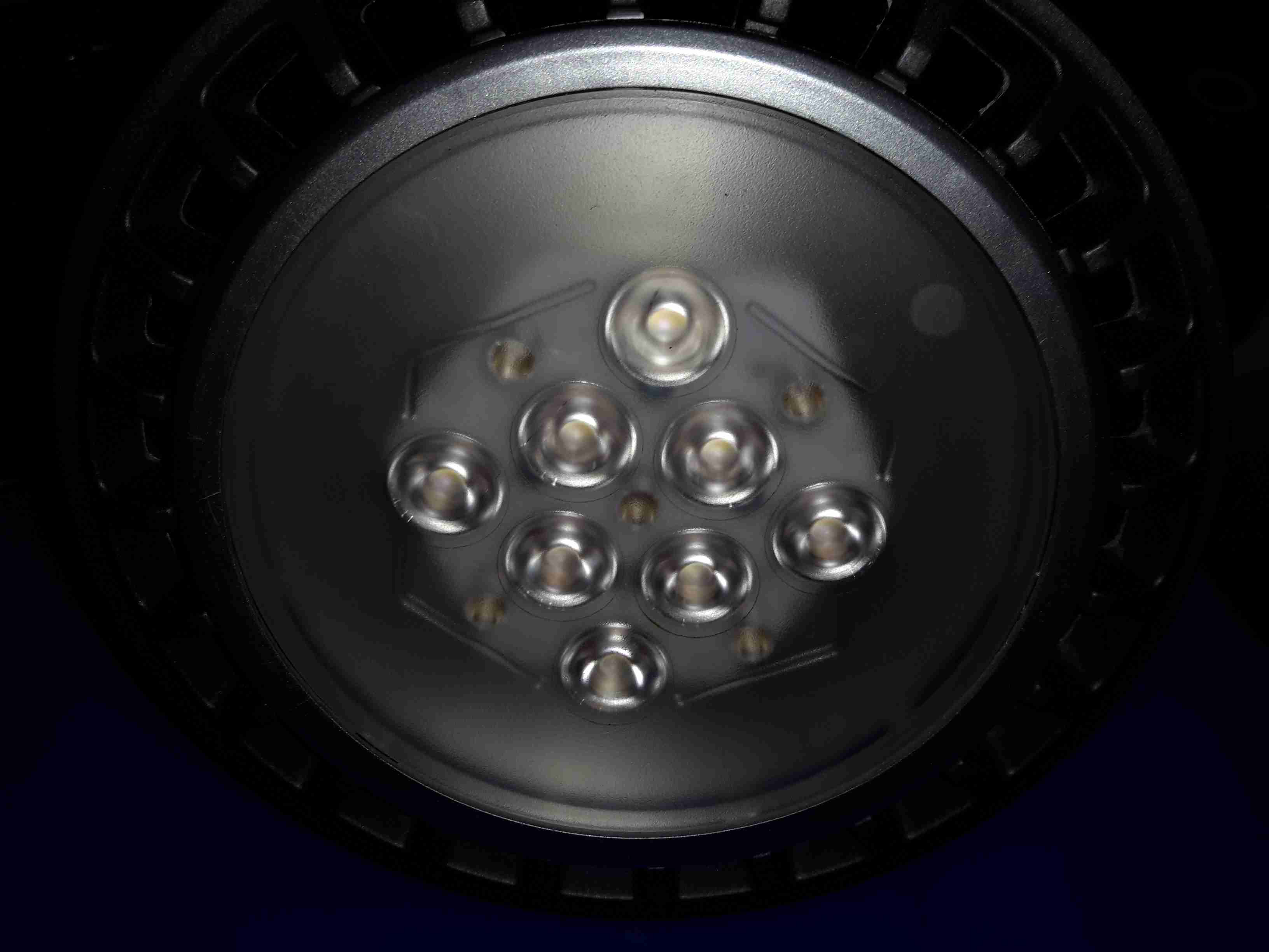
Lens
The front has the moulded multi-lens over the LEDs, to spread the light a bit further than the bare dies.
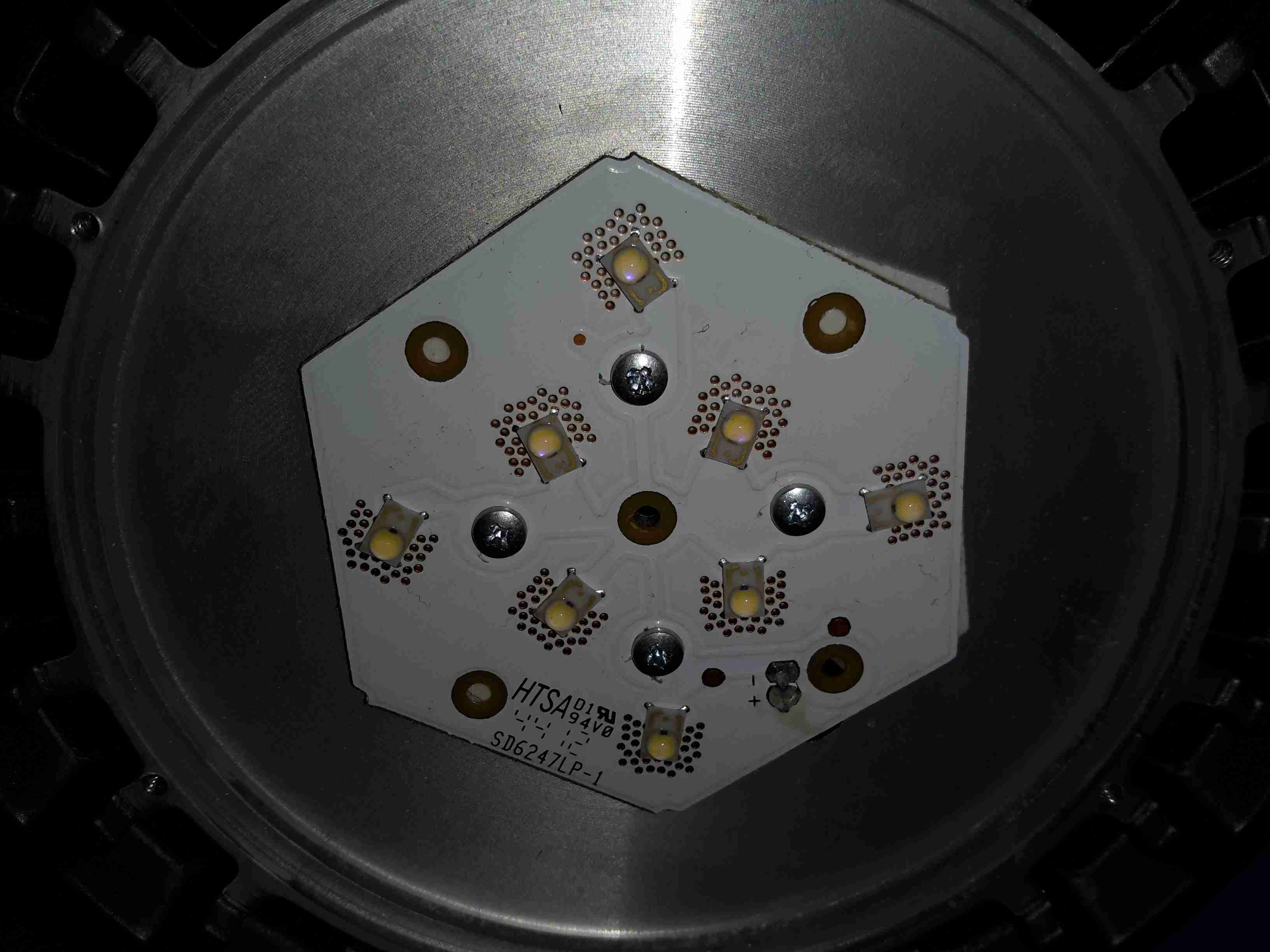
LED Array
The LED array is two series strings of 4 LEDs, for ~24v forward voltage. Unusual for a high power LED array, this PCB isn’t aluminium cored, but 0.8mm FR4. Heat is transferred to the copper plane on the backside by the dozens of vias around the Luxeon Rebel LEDs. There is a thermal pad under the PCB for improved heat transfer to the machined surface of the heatsink.
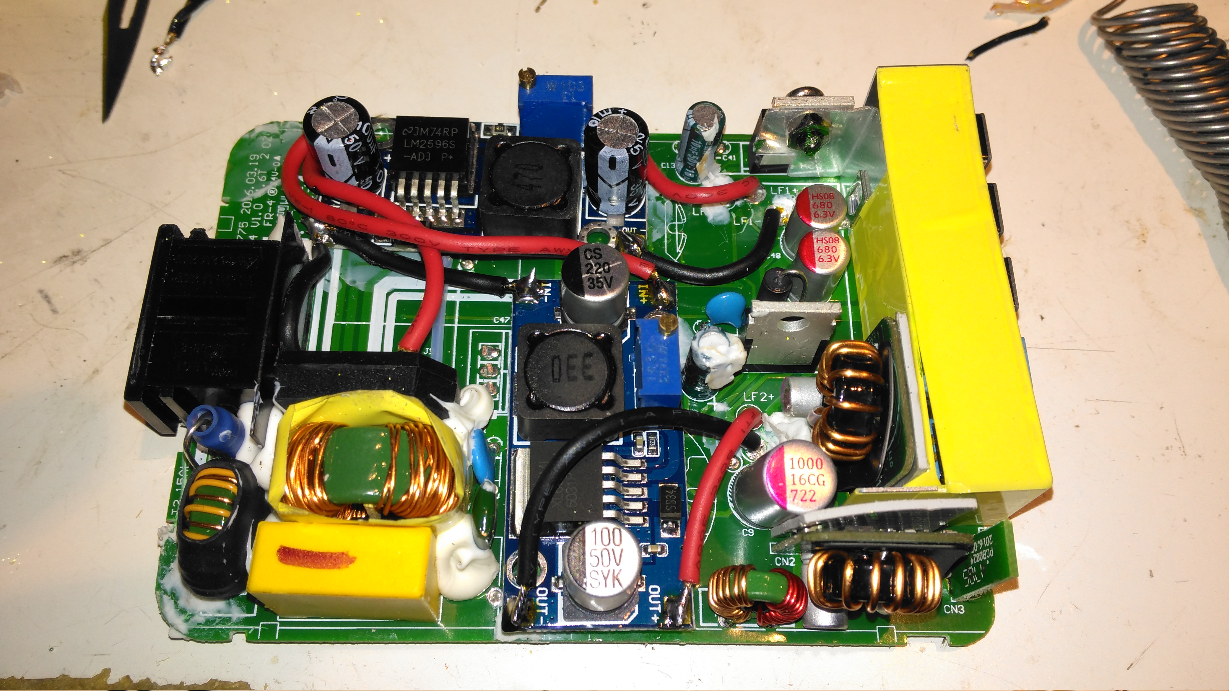
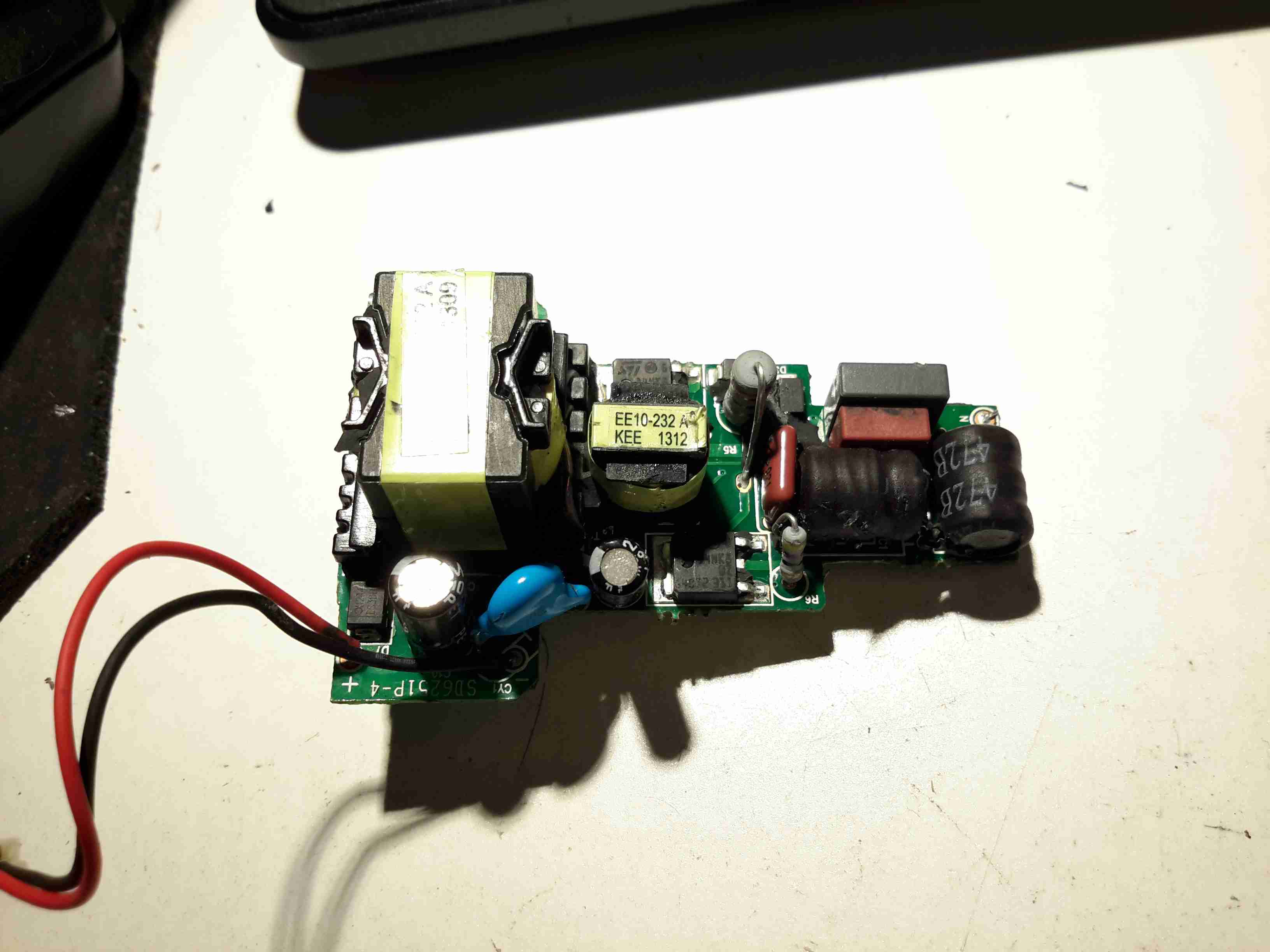
Control PCB Top
The power supply & control PCB is pretty well made, it’s an isolated converter, so no nasty mains on the LED connections.
I wrote a few weeks ago about replacing the hot water circulating pump on the boat with a new one, and mentioned that we’d been through several pumps over the years. After every replacement, autopsy of the pump has revealed the failure mode: the first pump failed due to old age & limited life of carbon brushes. The second failed due to thermal shock from an airlock in the system causing the boiler to go a bit nuts through lack of water flow. The ceramic rotor in this one just cracked.
The last pump though, was mechanically worn, the pump bearings nicely polished down just enough to cause the rotor to stick. This is caused by sediment in the system, which comes from corrosion in the various components of the system. Radiators & skin tanks are steel, engine block cast iron, back boiler stainless steel, Webasto heat exchanger aluminium, along with various bits of copper pipe & hose tying the system together.
The use of dissimilar metals in a system is not particularly advisable, but in the case of the boat, it’s unavoidable. The antifreeze in the water does have anti-corrosive additives, but we were still left with the problem of all the various oxides of iron floating around the system acting like an abrasive. To solve this problem without having to go to the trouble of doing a full system flush, we fitted a magnetic filter:
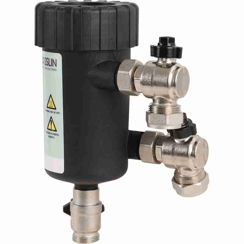
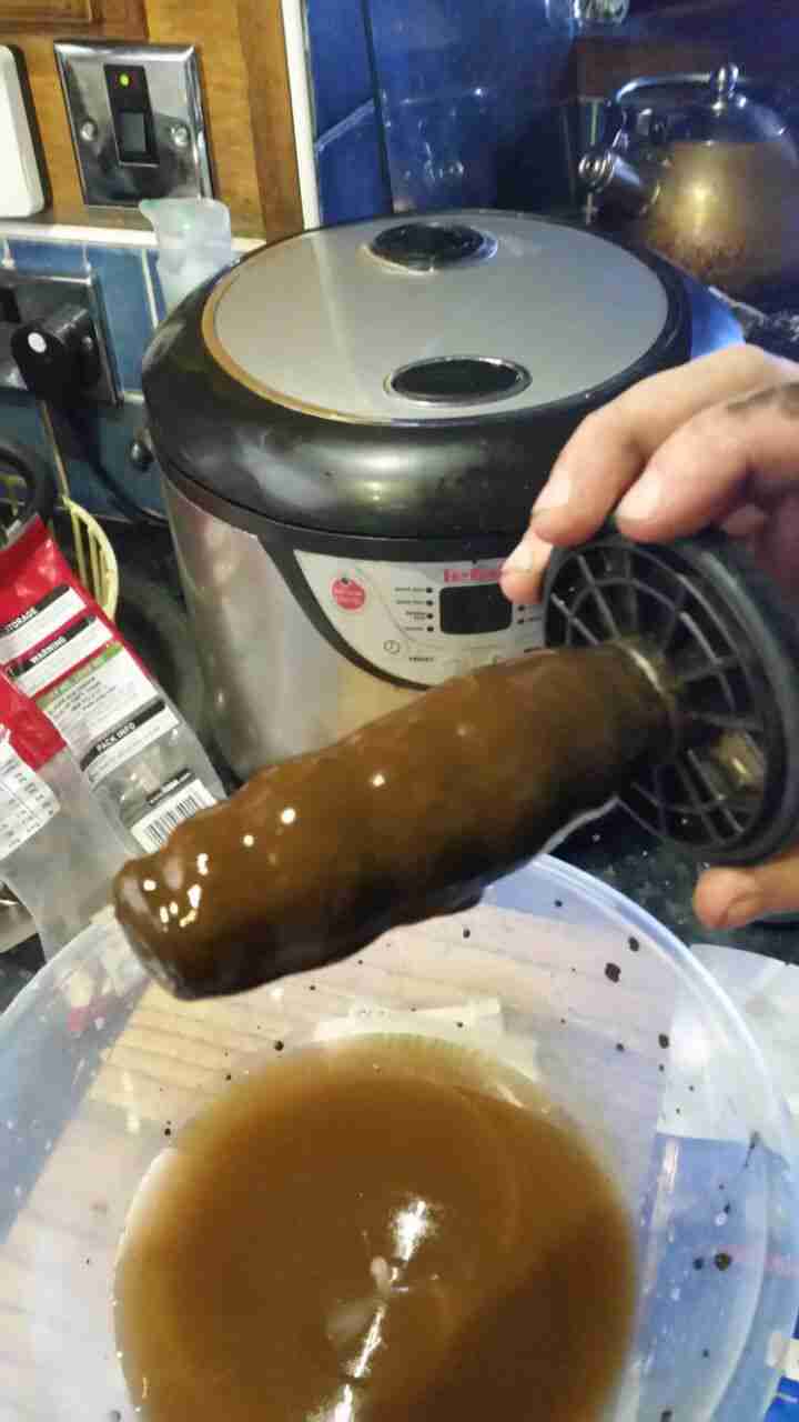
Mag Filter
This is just an empty container, with a powerful NdFeB magnet inserted into the centre. As the water flows in a spiral around the magnetic core, aided by the offset pipe connections, the magnet pulls all the magnetic oxides out of the water. it’s fitted into the circuit at the last radiator, where it’s accessible for the mandatory maintenance.
Sludge
Now the filter has been in about a month, I decided it would be a good time to see how much muck had been pulled out of the circuit. I was rather surprised to see a 1/2″ thick layer of sludge coating the magnetic core! The disgusting water in the bowl below was what drained out of the filter before the top was pulled. (The general colour of the water in the circuit isn’t this colour, I knocked some loose from the core of the filter while isolating it).
If all goes well, the level of sludge in the system will over time be reduced to a very low level, with the corrosion inhibitor helping things along. This should result in much fewer expensive pump replacements!
Prior to the introduction of the CD player, the red He-Ne laser was by far the most common source of inexpensive coherent light on the planet. The following are some typical physical specifications for a variety of red (632.8 nm) He-Ne tubes (all are single transverse mode – TEM00):
   Output       Tube Voltage       Tube         Tube Size
   Power        Operate/Start     Current      Diam/Length
 ------------  ---------------  ------------  -------------
  0.3-0.5 mW    0.8-1.0/6  kV    3.0-4.0 mA     19/135 mm
  0.5-1 mW       .9-1.0/7  kV    3.2-4.5 mA     25/150 mm
   1-2 mW       1.0-1.4/8  kV    4.0-5.0 mA     30/200 mm
   2-3 mW       1.1-1.7/8  kV    4.0-6.5 mA     30/260 mm
   3-5 mW       1.7-2.4/10 kV    4.5-6.5 mA     37/350 mm
   5-10 mW      2.4-3.1/10 kV    6.5-7.0 mA     37/440 mm
  10-15 mW      3.0-3.5/10 kV    6.5-7.0 mA     37/460 mm
  15-25 mW      3.3-4.0/10 kV    6.5-7.0 mA     37/600 mm
  25-35 mW      4.0-5.2/12 kV    7.0-8.0 mA     42/900 mm
Where:
Power Output is the minimum beam power after a specified warm up period over the spec’d life of the tube.
Tube Operating Voltage is the voltage across the bare tube at the nominal operating current.
Tube Start Voltage is the minimum voltage across the bare tube required to guarantee starting.
Tube Size is generally the maximum diameter of the tube envelope and the total length from the outer surfaces of the mirrors.
Tubes like this are generally available in both random and linearly polarized versions which are otherwise similar with respect to the above characteristics (for red tubes at least, more below).
At least one other basic specification may be critical to your application: Which end of the tube the beam exits! There is no real preference from a manufacturing point of view for red He-Ne lasers. (For low gain “other-colour” He-Ne laser tubes, it turns out that anode output results is slightly higher gain and thus slightly higher output for the typical hemispherical cavity because it better utilizes the mode volume.) However, this little detail may matter a great deal if you are attempting to retrofit an existing barcode scanner or other piece of equipment where the tube clips into a holder or where wiring is short, tight, or must be in a fixed location. For example, virtually all cylindrical laser heads require that the beam exits from the cathode-end of the tube. It is possible that you will be able to find two versions of many models of He-Ne tubes if you go directly to the manufacturer and dig deep enough. However, this sort of information may not be stated where you are buying surplus or from a private individual, so you may need to ask.
The examples above (as well as all of the other specifications in this and the following sections) are catalog ratings, NOT what might appear on the CDRH safety sticker (which is typically much higher). See the section: About Laser Power Ratings for info on listed, measured, and CDRH power ratings.
Note how some of the power levels vary widely with respect to tube dimensions, voltage, and current. Generally, higher power implies a longer tube, higher operating/start voltages, and higher operating current – but there are some exceptions. In addition, you will find that physically similar tubes may actually have quite varied power output. This is particularly evident in the manufacturers’ listings. (See the chapter: A HREF=”laserhcl.htm#hcltoc”>Commercial Unstabilized HeNe Lasers.)
These specifications are generally for minimum power over the guaranteed life of the tube. New tubes and individual sample tubes after thousands of hours may be much higher – 1.5X is common and a “hot” sample may hit 2X or more. My guess is that for tubes with identical specifications in terms of physical size, voltage, and current, the differences in power output are due to sample-to-sample variations. Thus, like computer chips, they are selected after manufacture based on actual performance and the higher power tubes are priced accordingly! This isn’t surprising when considering the low efficiency at which these operate – extremely slight variations in mirror reflectivity and trace contaminants in the gas fill can have a dramatic impact on power output.
I have a batch of apparently identical 2 mW Aerotech tubes that vary in power output by a factor of over 1.5 to 1 (2.6 to 1.7 mW printed by hand on the tubes indicating measured power levels at the time of manufacture).
And, power output also changes with use (and mostly in the days of soft-sealed tubes, just with age sitting on the shelf):
(From: Steve Roberts.)
“I have a neat curve from an old Aerotech catalogue of He-Ne laser power versus life. The tubes are overfilled at first, so power is low. They then peak at a power much higher than rated power, followed by a long period of constant power, and then they SLOWLY die. It’s not uncommon for a new He-Ne tube to be in excess of 15% greater than rated power.”
And the answer to your burning question is: No, you cannot get a 3 mW tube to output 30 mW – even instantaneously – by driving it 10 times as hard!
I have measured the operating voltage and determined the optimum current (by maximizing beam intensity) for the following specific samples – all red (632.8 nm) tubes from various manufacturers. (The starting voltages were estimated.):
   Output     Tube Voltage       Tube         Supply Voltage     Tube Size
   Power      Operate/Start     Current        (75K ballast)    Diam/Length
 ----------  ---------------  ------------   ----------------  -------------
    .8 mW        .9/5  kV        3.2 mA           1.1 kV         19/135 mm
   1.0 mW       1.1/7  kV        3.5 mA           1.4 kV         25/150 mm
   1.0 mW       1.1/7  kV        3.2 mA           1.4 kV         25/240 mm
   2.0 mW       1.2/8  kV        4.0 mA           1.5 kV         30/185 mm
   3.0 mW       1.6/8  kV        4.5 mA           1.9 kV         30/235 mm
   5.0 mW       1.7/10 kV        6.0 mA           2.2 kV         37/350 mm
  12.0 mW       2.5/10 kV        6.0 mA           2.9 kV         37/475 mm
Melles Griot, Uniphase, Siemens, PMS, Aerotech, and other HeNe tubes all show similar values.
The wide variation in physical dimensions also means that when looking at descriptions of He-Ne lasers from surplus outfits or the like, the dimensions can only be used to determine an upper (and possibly lower) bound for the possible output power but not to determine the exact output power (even assuming the tube is in like-new condition). Advertisements often include the rating on the CDRH safety sticker (or say ‘max’ in fine print). This is an upper bound for the laser class (e.g., Class IIIa), not what the particular laser produces or is even capable of producing. It may be much lower. For example, that Class IIIa laser showing 5 mW on the sticker, may actually only be good for 1 mW under any conditions! The power output of a He-Ne laser tube is essentially constant and cannot be changed significantly by using a different power supply or by any other means. See the section: Buyer Beware for Laser Purchases.
In addition to power output, power requirements, and physical dimensions, key performance specifications for He-Ne lasers also include:
Beam Diameter at the laser’s output aperture and beam profile (Gaussian TEM00 for most small He-Ne laser tubes).
Beam Divergence (probably far field ignoring beam waist). Note that this may not always be the same as the expected value from the diffraction limit based on beam/bore diameter as it also depends on the combination of the HR and OC mirror (inside) curvature and the shape of the exterior surface of the OC.
Mode Spacing (frequency) between the multiple longitudinal modes that are active simultaneously in all but single mode frequency stabilized lasers.
With manufacturers like Aerotech, Melles Griot, and Siemens, a certain amount of information can be determined from the model number. For example, here is how to decipher most of those from Melles Griot (e.g., 05-LHP-121-278):
All Melles Griot He-Ne laser tubes and power supplies start with 05. Matched systems may start with 25 (e.g., laser head and lab-style power supply).
The first letter will be an L for all He-Ne laser tubes and heads except for perpendicular window terminated tubes (in which case it will be W – this is inconsistent with the rest of their numbering but who am I to complain!), and some of their self contained lasers where it will be S.
The second letter will be one of: H = red (632.8 nm), G = green (543.5 nm), Y = yellow (594.1 nm), O = orange (611.9 nm), or I = infra-red (1,523 or 3,391 nm). A couple of self contained red lasers use R for red but for most, I guess they got stuck using H (presumably denoting He-Ne) before ‘other colour’ He-Ne lasers were part of their product line. And, their stabilized He-Ne lasers use a T here. Confused yet? 🙂
The third letter will be one of: R = Randomly polarized, L = linearly polarized, or B = Brewster window at one or both ends.
The following three digit number determines the physical characteristics of the laser tube to some extent. Unfortunately, there may be no direct mathematical relationship of this number to anything useful. As will be seen below, for some models, it (or some of its digits) sort of correlates with output power or length but for others, they might as well be totally random! However, it does appear as though an identical set of numbers among different colour tubes (see below) will denote similar physical size tubes at least.
If there are additional numbers, they relate to a special variation on the basic design done for a particular customer. For example, this might be a different curvature on the outer surface of the output mirror to provide a non-standard divergence to eliminate the need for an additional lens in a barcode scanner. Or, an external window for protection from the elements or to deliberately reduce output power. Go figure. 🙂 It may also just denote a specific configuration like -249 (meaning 115 VAC operation, kind of arbitrary, huh?) or -55 (meaning 5.5 mA). In these cases, the user may be able to modify the settings (flip a switch or twiddle a pot) but the warranty may then be void.
The vast majority of Melles Griot lasers you are likely to come across will follow this numbering scheme though there are some exceptions, especially for custom assemblies. (Some surplus places drop the leading ’05-‘ when reselling Melles Griot laser tubes or heads so an 05-LHP-120 would become simply an LHP-120.)
For other manufacturers like Spectra-Physics, the model numbers are totally arbitrary!
He-Ne Tubes of a Different Colour
Although a red beam is what everyone thinks of when a He-Ne laser is discussed, He-Ne tubes producing green, yellow, and orange beams, as well as several infra-red (IR) wavelengths, are also manufactured. However, they are not found as often on the surplus market because they are not nearly as common as the red variety. In terms of the number of He-Ne lasers manufactured, red is far and away the most popular, with all the others combined accounting for only 1 to 2 percent of the total production. In order of decreasing popularity, it’s probably: red, green, yellow, infra-red (all IR wavelengths), orange. Non-red tubes are also more expensive when new since for a given power level, they must be larger (and thus have higher voltage and current ratings) due to their lower efficiency (the spectral lines being amplified are much weaker than the one at 632.8 nm). Operating current for non-red He-Ne tubes is also more critical than for the common red variety so setting these up with an adjustable power supply or adjusting the ballast resistance for maximum output is recommended.
Maximum available power output is also lower – rarely over 2 mW (and even those tubes are quite large (see the tables below). However, since the eye is more sensitive to the green wavelength (543.5 nm) compared to the red (632.8 nm) by more than a factor of 4, a lower power tube may be more than adequate for many applications. Yellow (594.1 nm) and orange (611.9 nm) He-Ne lasers appear more visible by factors of about 3 and 2 respectively compared to red beams of similar power.
Infrared-emitting He-Ne lasers exist as well. In addition to scientific uses, these were used for testing in the Telecom industry before sufficiently high quality diode lasers became available.Yes, you can have a He-Ne tube and it will light up inside (typical neon glow), but if there is no output beam (at least you cannot see one), you could have been sold an infrared He-Ne tube. However, by far the most likely explanation for no visible output beam is that the mirrors are misaligned or the tube is defective in some other way. Unfortunately, silicon photodiodes or the silicon sensors in CCD or CMOS cameras do not respond to any of the He-Ne IR wavelengths, so the only means of determining if there is an IR beam are to use a GaAs photodiode, IR detector card, or thermal laser power meter. IR He-Ne tubes are unusual enough that it is very unlikely you will ever run into one. However, they may turn up on the surplus market especially if the seller doesn’t test the tubes and thus realize that these behave differently – they are physically similar to red (or other colour) He-Ne tubes except for the reflectivity of the mirrors as a function of wavelength. (There may be some other differences needed to optimize each color like the He:Ne ratio, isotope purity, and gas fill pressure, but the design of the mirrors will be the most significant factor and the one that will be most obvious with a bare eyeball, though the color of the discharge may be more pink for green He-Ne tubes and more orange and brighter for IR He-Ne tubes compared to red ones, more below.) Even if the model number does not identify the tube as green, yellow, orange, red, or infra-red, this difference should be detectable by comparing the appearance of its mirrors (when viewed down the bore of an UNPOWERED tube) with those of a normal (known to be red) He-Ne tube. (Of course, your tube could also fail to lase due to misaligned or damaged mirrors or some other reason.
As noted above, the desired wavelength is selected and the unwanted wavelengths are suppressed mostly by controlling the reflectivity functions of the mirrors. For example, the gains of the green and yellow lines (yellow may be stronger) are both much much lower than red and separated from each other by about 50 nm (543.5 nm versus 594.1 nm). To kill the yellow line in a green laser, the mirrors are designed to reflect green but pass yellow. I have tested the mirrors salvaged from a Melles Griot 05-LGP-170 green He-Ne tube (not mine, from “Dr. Destroyer of Lasers”). The HR (High Reflector) mirror has very nearly 100% reflectivity for green but less than 25% for yellow. The OC (Output Coupler) also has a low enough reflectivity for yellow (about 98%) such that it alone would prevent yellow from lasing. The reflectivities for orange, red, and IR, are even lower so they are also suppressed despite their much higher gain, especially for the normal red (632.8 nm) and even stronger mid-IR (3,391 nm) line.
However, to manufacture a tube with optimum and stable output power, it isn’t sufficient to just kill lasing for unwanted lines. The resonator must be designed to minimize their contribution to stimulated emission – thus the very low reflectivity of the HR for anything but the desired green wavelength. Otherwise, even though sustained oscillation wouldn’t be possible, unwanted colour photons would still be bouncing back and forth multiple times stealing power from the desired colour. The output would also be erratic as the length of the tube changed during warm up (due to thermal expansion) and this affected the longitudinal mode structure of the competing lines relative to each other. Some larger He-Ne lasers have magnets along the length of the tube to further suppress (mostly) the particularly strong mid-IR line at 3,391 nm. (See the section: Magnets in High Power or Precision HeNe Laser Heads.)
In addition, you can’t just take a tube designed for a red laser, replace the mirrors, and expect to get something that will work well – if at all – for other wavelengths. For one thing, the bore size and mirror curvature for maximum power while maintaining TEM00 operation are affected by wavelength.
Furthermore, for these other colour He-Ne lasers which depend on energy level transitions which have much lower gain than red – especially the yellow and green ones – the gas fill pressure, He:Ne ratio, and isotopic composition and purity of the helium and neon, will be carefully optimized and will be different than for normal red tubes.
Needless to say, the recipes for each type and size laser will be closely guarded trade secrets and only a very few companies have mastered the art of other colour He-Ne lasers, especially for high power (in a relative sort of way) in yellow and green. I am only aware of four companies that currently manufacture their own tubes: Melles Griot, Research Electro-Optics, Uniphase, and LASOS, with the last two having very few models to choose from. Others (like Coherent) simply resell lasers under their own name.
And, the answer to that other burning question should now be obvious: No, you can’t convert an ordinary red internal mirror He-Ne tube to generate some other colour light as it’s (almost) all done with mirrors and they are an integral part of the tube. 🙂 Therefore, your options are severely limited. As in: There are none. (However, going the other way, at least as a fun experiment, may be possible. For a laser with external mirrors, a mirror swap may be possible (though the cavity length may be insufficient to resonate with the reduced gain of other-colour spectral lines once all loses taken into consideration). But realistically, this option doesn’t even exist where the mirrors are sealed into the tube.
There are also a few He-Ne lasers that can output more than one of the possible colors simultaneously (e.g., red+orange, orange+yellow) or selectively by turning knob (which adjusts the angle of a Littrow or other similar dispersion prism) inside the laser cavity using a Brewster window He-Ne tube). But such lasers are not common and are definitely very expensive. So, you won’t likely see one for sale at your local hamfest – if ever! One manufacturer of such lasers is Research Electro-Optics (REO). See the section: Research Electro-Optics’s Tunable HeNe Lasers.
However, occasionally a He-Ne tube turns up that is ‘defective’ due to incorrect mirror reflectivities or excessive gain or magic 🙂 and actually outputs an adjacent colour in addition to what it was designed to produce. I have such a tube that generates about 3 mW of yellow (594.1 nm) and a fraction of a mW of orange (611.9 nm) but isn’t very stable – power fluctuates greatly as it warms up. Another one even produces the other orange line at 611.9 nm, and it’s fairly stable. But, finding magic ‘defective’ tubes such as these by accident is extremely unlikely though I’ve heard of the 640.1 nm (deep red) line showing up on some supposedly good normal red (632.8 nm) He-Ne tubes.
As a side note: It is strange to see the more or less normal red-orange glow in a green He-Ne laser tube but have a green beam emerging. A diffraction grating or prism really shows all the lines that are in the glow discharge. Red through orange, yellow and green, even several blue lines (though they are from the helium and can’t lase under any circumstances)!! The IR lines are present as well – you just cannot see them.
Actually, the colour of the discharge may be subtly different for non-red He-Ne tubes due to modified gas fill and pressure. For example, the discharge of green He-Ne tubes may appear more pink compared to red tubes) which are more orange), mostly due to lower fill pressure. The fill mix and pressure on green He-Ne tubes is a tricky compromise among several objectives that conflict to some extent including lifetime, stability (3.39µm competition), and optical noise. This balancing act and the lower fill pressure are why green He-Ne tubes don’t last as long as reds. Have I totally confused you, colour-wise? 🙂
The expected life of ‘other colour’ He-Ne tubes is generally much shorter than for normal red tubes. This is something that isn’t widely advertised for obvious reasons. Whereas red He-Ne tubes are overfilled initially (which reduces power output) and they actually improve with use to some extent as gas pressure goes down, this luxury isn’t available with the low gain wavelengths – especially green – everything needs to be optimal for decent performance.
The discharge in IR He-Ne tubes may be more orange and brighter due to a higher fill pressure. Again, this is due to the need to optimize parameters for the specific wavelength.
Determining He-Ne Laser Colour from the Appearance of the Mirrors
Although most He-Ne lasers are the common red (632.8 nm) variety (whose beam actually appears orange-red), you may come across unmarked He-Ne tubes and just have to know what colour output the produce without being near a He-Ne laser power supply.
Since the mirrors used in all He-Ne lasers are dielectric – functioning as a result of interference – they have high reflectivity only around the laser wavelength and actually transmit light quite well as the wavelength moves away from this peak. By transmitted light, the appearance will tend to be a colour which is the complement of the laser’s output – e.g., cyan or blue-green for a red tube, pink or magenta for a green tube, blue or violet for a yellow tube. Of course, except for the IR variety, if the tube is functional, the difference will be immediately visible when it is powered up!
The actual appearance may also depend on the particular manufacturer and model as well as the length/power output of the laser (which affects the required reflectivity of the OC), as well as the revision number of your eyeballs. 🙂 So, there could be considerable variation in actual perceived colour. Except for the blue-green/magenta combination which pretty much guarantees a green output He-Ne tube, more subtle differences in colour may not indicate anything beyond manufacturing tolerances.
Appearance of He-Ne Laser Mirrors
The chart above in conjunction with will help to identify your unmarked He-Ne tube. (For accurate rendition of the graphic, your display should be set up for 24 bit colour and your monitor should be adjusted for proper colour balance.)
      HeNe Laser          High Reflector (HR)          Output Coupler (OC)
   Color  Wavelength   Reflection   Transmission    Reflection   Transmission
 ------------------------------------------------------------------------------
    Red    632.8 nm    Gold/Copper      Blue        Gold/Yellow   Blue/Green
   Orange  611.9 nm   Whitish-Gold      Blue       Metallic Green   Magenta
   Yellow  594.1 nm   Whitish-Gold      Blue       Metallic Green   Magenta
   Green   543.5 nm   Metallic Blue  Red/Orange    Metallic Green   Magenta

   Broadband (ROY)    Whitish-Gold      Blue

    IR     1,523 nm    Light Green  Light Magenta   Light Green  Light Magenta
    IR     3,391 nm       Gold (Metal) Coated         Neutral        Clear
The entry labelled ‘Broadband’ relates to the HR mirror in some unusual multiple colour (combinations of red and/or orange and/or yellow) internal mirror tubes as well as those with an internal HR and Brewster window for external OC optics. And, the yellow and orange tubes may actually use broad band HRs. The OCs would then be selected for the desired wavelength(s) and may also have a broad band coating.
For low gain tubes, they play games with the coatings. I guess it isn’t possible to just make a highly selective coating for one wavelength that’s narrow enough to have low reflectivity at the nearby lines so they won’t lase. So, one mirror will be designed to fall off rapidly on one side of the design wavelength, the other mirror on the other side. That’s one reason front and back mirrors on yellow and green tubes in particular have very different appearances.
As noted, depending on laser tube length/output power, manufacturer, and model, the appearance of the mirrors can actually vary quite a bit but this should be a starting point at least. For example, I have a Melles Griot 05-LHR-170 He-Ne laser tube that should be 594.1 nm (yellow) but actually outputs some 604.6 nm (orange) as well. It’s mirror colours for the HR and OC are almost exactly opposite of those I have shown for the yellow and orange tubes! I don’t know whether this was intentional or part of the problem And, while from this limited sample, it looks like the OCs for orange, yellow, and green He-Ne lasers appear similar, I doubt that they really are in the area that counts – reflectivity/transmission at the relevant wavelengths.
More on Other Colour He-Ne Lasers
Here are some comments on the difficulty of obtaining useful visible output from He-Ne lasers at wavelengths other than our friendly red (632.8 nm):
(From: Steve Roberts.)
You do need a isotope change in the gases for green, and a He:Ne ratio change for the other orange and yellow lines. In addition, the mirrors to go to another line will have a much lower output transmission. The only possible lines you’ll get on a large frame He-Ne laser will be the 611.9 nm orange and 594.1 nm yellow. The green requires external mirror tubes in excess of a meter and a half long and a Littrow prism to overcome the Brewster losses and suppress the IR.
The original work on green was done by Rigden and Wright. The short tubes have lower losses because they have no Brewsters and thus can concentrate on tuning the coatings to 99.9999% reflectivity and maximum IR transmission. There is one tunable low power unit on the market that does 6 lines or so, but only 1 line at a time, and the $6,000 cost is kind of prohibitive for a few milliwatts of red and fractional milliwatt powers on the other lines. But, it will do green and has the coatings on the back side of the prism to kill the losses.
Also look for papers by Erkins and Lee. They are the fellows who did the green and yellow for Melles Griot and they published one with the energy states as part of a poster session at some conference. Melles Griot used to hand it out, that’s how I had a copy, recently thrown away.
Even large He-Ne lasers such as the SP-125 (rated at 50mW of red) will only do about 20mW of yellow, with a 35mW SP-127 you’re probably only looking at 3 to 5mW of yellow. And, for much less then the cost of the custom optics to do a conversion, you can get two or three 4 to 5 mW yellow heads from Melles Griot. I know for a fact that a SP-127 only does about 3mW of 611.9 with a external prism and a remote cavity mirror, when it does 32mW of 632.8nm.
So in the end, unless you have a research use for a special line, it’s cheaper to dig up a head already made for the line you seek, unless you have your own optics coating lab that can fabricate state-of-the-art mirrors.
I have some experience in this, as I spent months looking for a source of the optics below $3,000.
(From: Sam.)
I do have a short (265 mm) one-Brewster He-Ne tube (Melles Griot 05-LGB-580) with its internal HR optimized for green that operates happily with a matching external green HR mirror (resulting in a nice amount of circulating power) but probably not with anything having much lower reflectivity to get a useful output beam. In fact, I could not get reliable operation even with the HR from a dead green He-Ne laser tube as the Brewster window would not remain clean enough for the time required to align the mirror.
I would expect an SP-127 to do more than 3 to 5 mW of yellow, my guess would be 10 to 15 mW with optimized mirrors but no tuning prism. If I can dig up appropriate mirrors, I intend to try modifying an SP-127 to make it tunable and/or do yellow or green. 🙂
You can find 640.1 nm in a lot of red He-Ne lasers. I have a paper on it somewhere, and cavity design can influence it to a large extent. If you have a decent quality grating, it’s pretty easy to pick up. 629 nm is the one you don’t see too much.
I’m no physicist, but the lower gain lines can lase simultaneously with the higher gain lines, no problem, as long as there is sufficient gain available in the plasma. It’s really pretty easy to get a He-Ne laser to output on all lines at the same time (if you have the right mirrors). The trick is optimizing the bore-to-mode ratio, gas pressure, and isotope mixture to get good TEM00 power. Usually the all-lines He-Ne lasers are multi (transverse) mode. I don’t know of anyone who makes them commercially though – at least not intentionally.
Steve’s Comments on Superradiance and the 3.39µm He-Ne Laser
Generally, when a gas laser is superradiant, there is a limit to its maximum power output (with exceptions for nitrogen and copper vapour laser, although nitrogen’s upper limit is defined by the maximum cavity length into which you can generate a 300ns or less excitation pulse.
The 3.39µm He-Ne laser’s gain is still, like all other He-Ne lines limited by a wall collision to return the excited atoms to the ground state. 3.39 µm He-Ne lasers have larger bores then normal He-Ne lasers, and the bores are acid etched to fog them and create more surface area, but still the most power I’ve ever seen published was 40 mW – nothing to write home about. The massive SP-125, the largest commercial He-Ne laser, could be ordered with a special tube and special optics for 3.39µm, and it still only did about 1/3rd the visible power. Superradiance and ultimate power are not tied together.
The reason 3.39µm got all the writeups it did was that it started on the same upper state as all the other He-Ne lines, was easily noticed when it sapped power from the visible line, and was, at the time, a exotic wavelength for which there were few other sources.
For my latest project, I needed an easier way to paint without messing about with brushes, and the associated marks they leave in a paint job. eBay provided me with a cheap airbrush & compressor.
Airbrush Kit
For less than £30, this kit doens’t look so bad. I’ve never used an airbrush before, but I’ve had no problems with this as yet spraying both water based paints & solvent based paints.
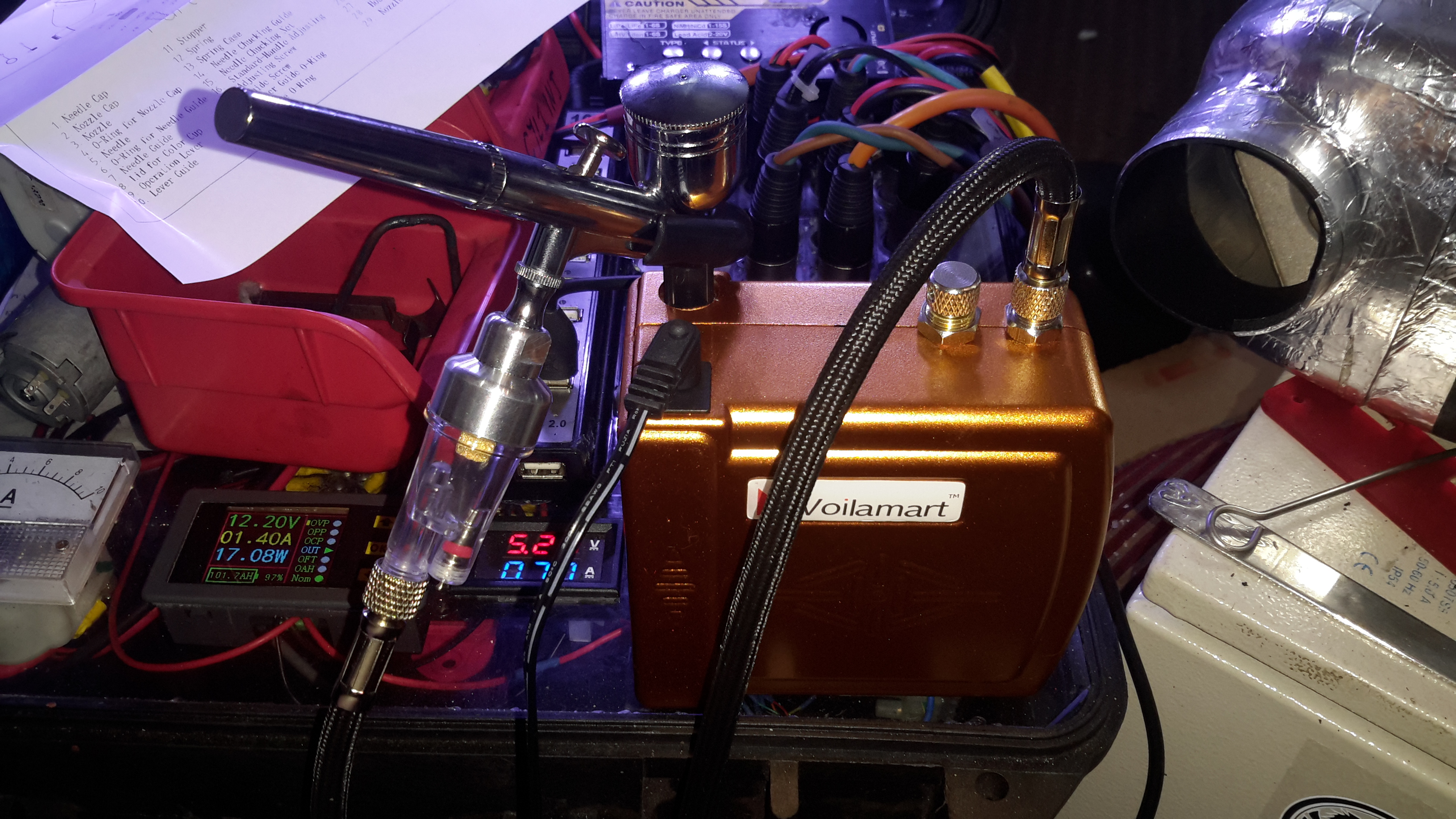
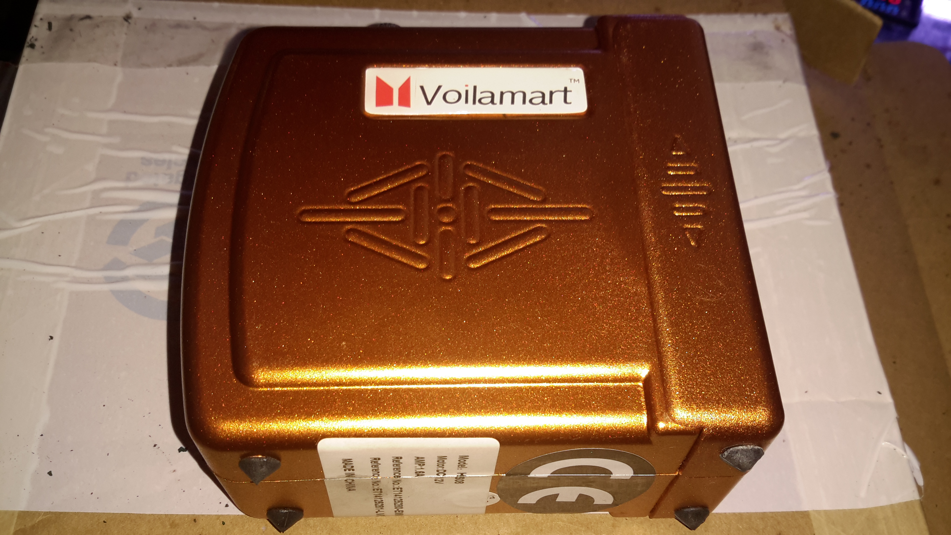
Compressor
Here’s the compressor itself, this runs on 12v & has an output pressure of 1.5 Bar, which is supposed to be adjustable.
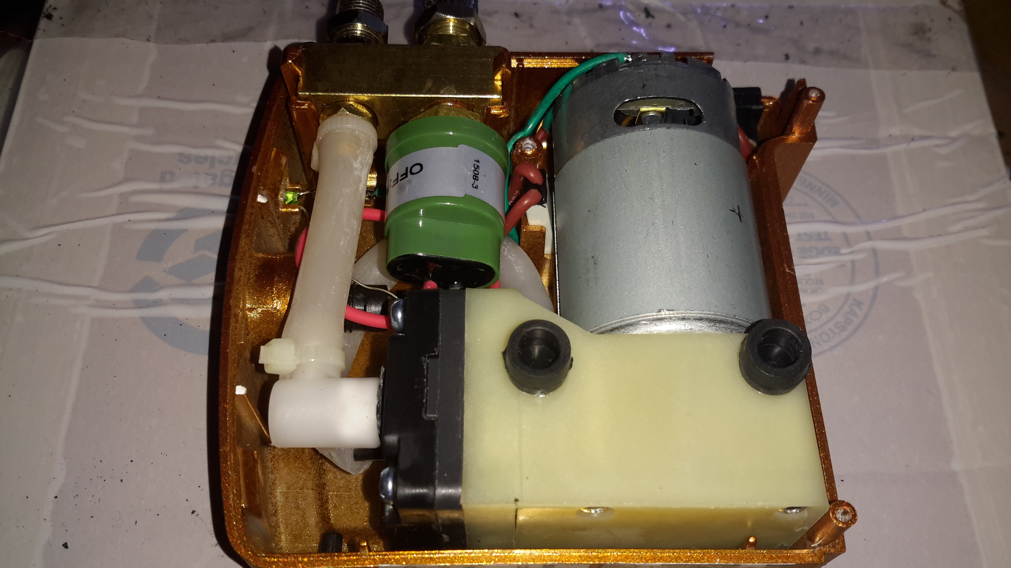
Compressor Internals
Removing a couple of screws reveals the internal components. Nothing much unusual here, a DC diaphragm pump, pressure switch & outlet fittings. There’s also a thermal cutout fitted next to the motor for protection.
The pressure switch attached to the manifold trips at 1.5Bar, keeping the pressure to the brush pretty much constant.
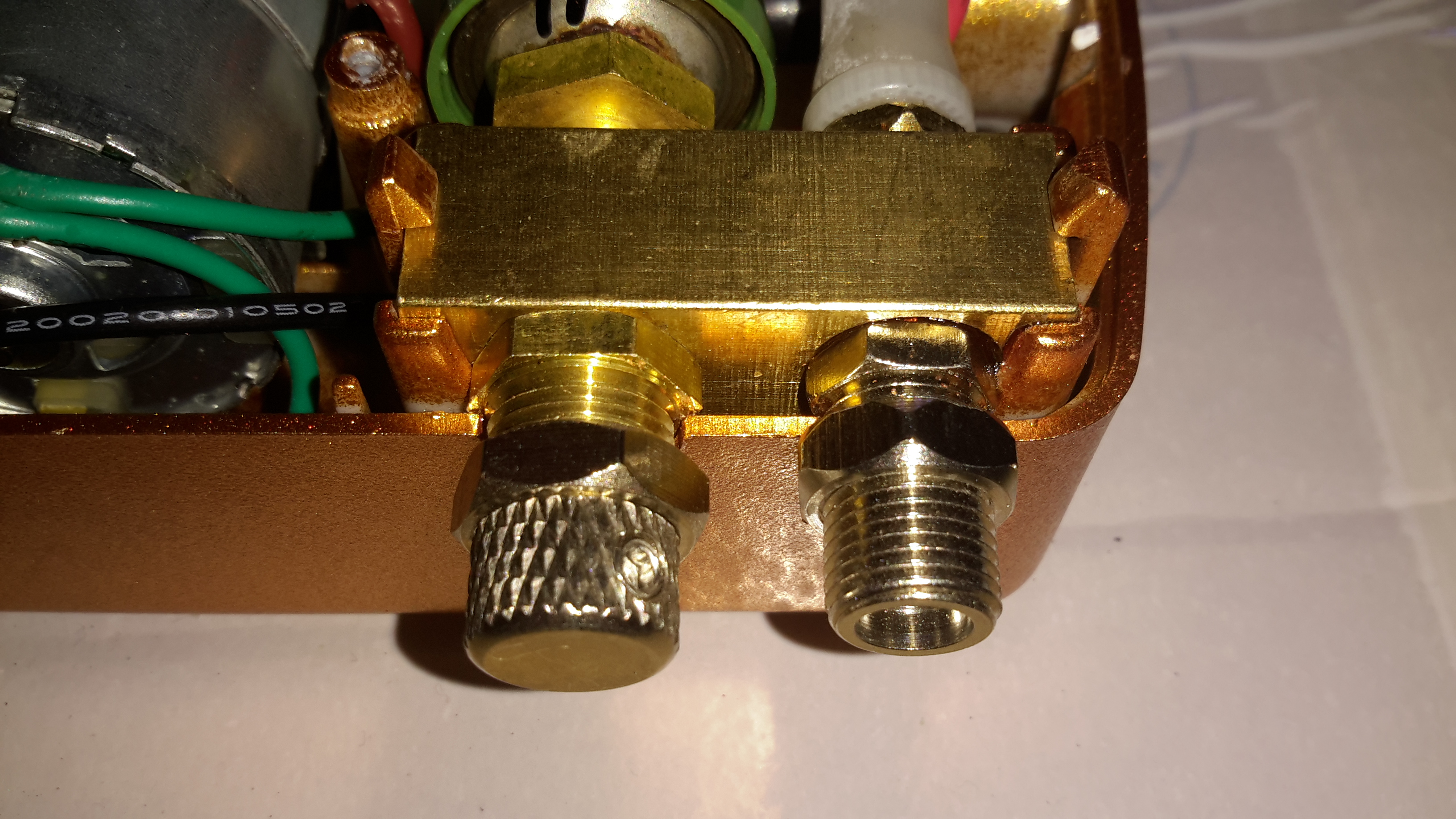
Air Block
Next to the air outlet fitting is an adjustment knob, supposedly for varying the pressure. However it’s just a piss-poorly designed adjustable relief valve that vents to atmosphere. There’s not much of a control range.
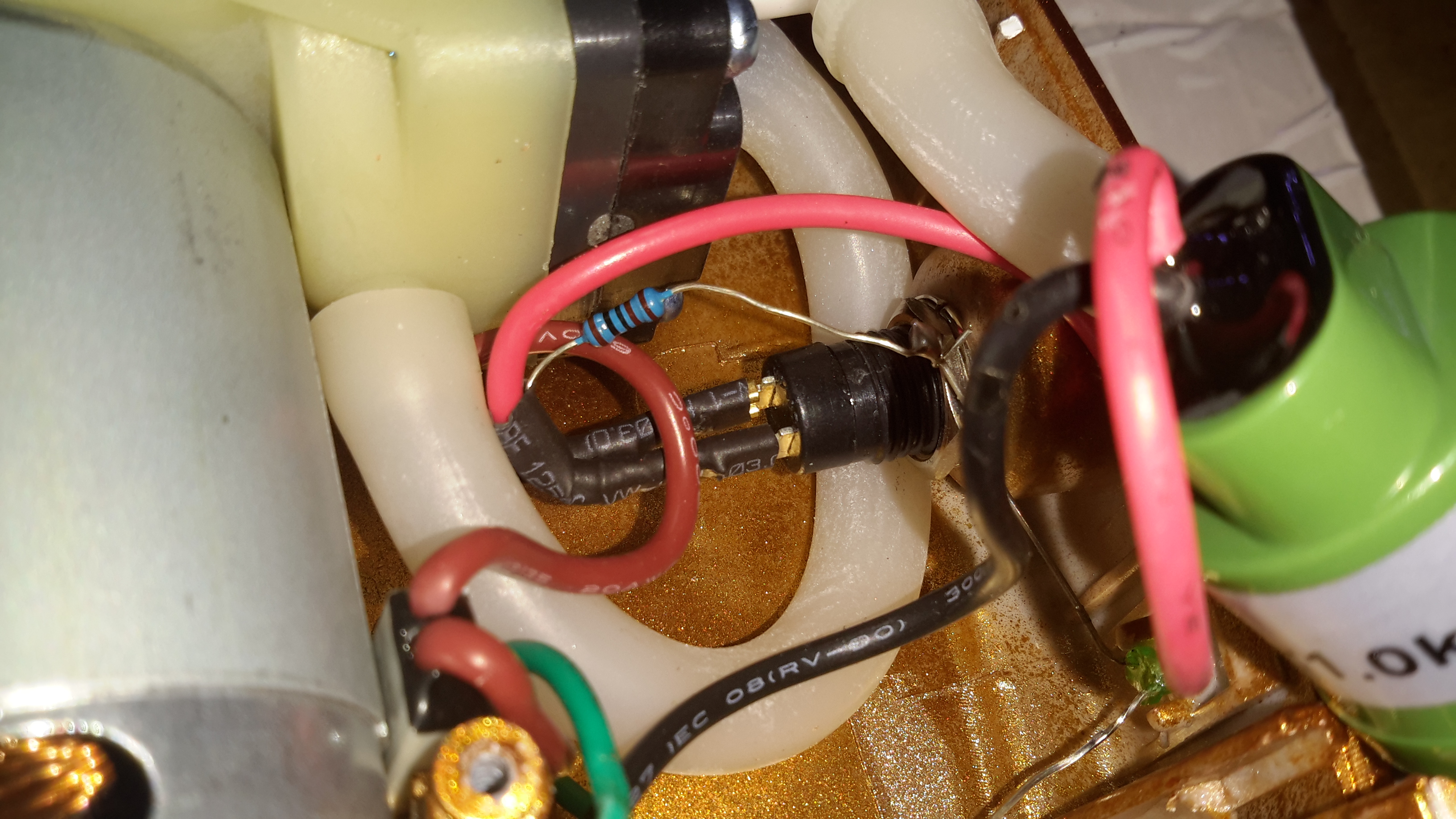
Messy Wiring
The wiring gets a bit messy where the power LED is concerned, with no heatshrink over the solder joints, but it’s adequate.
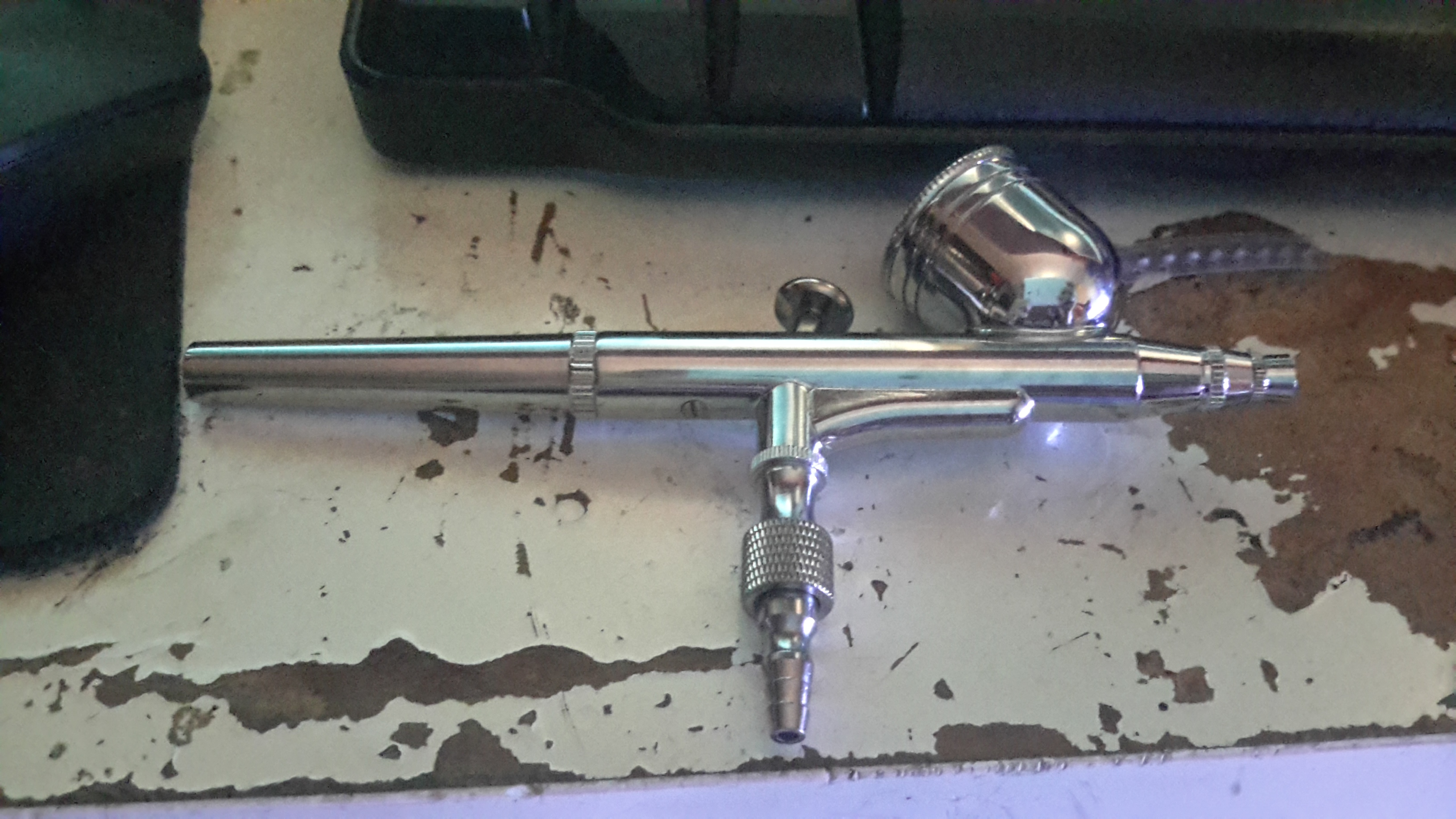
Airbrush
The airbrush itself isn’t too bad. It’s solid Brass, with a very nice Chrome finish. I’m not expecting miracles from a very cheap tool, but it certainly seems to be reasonable.
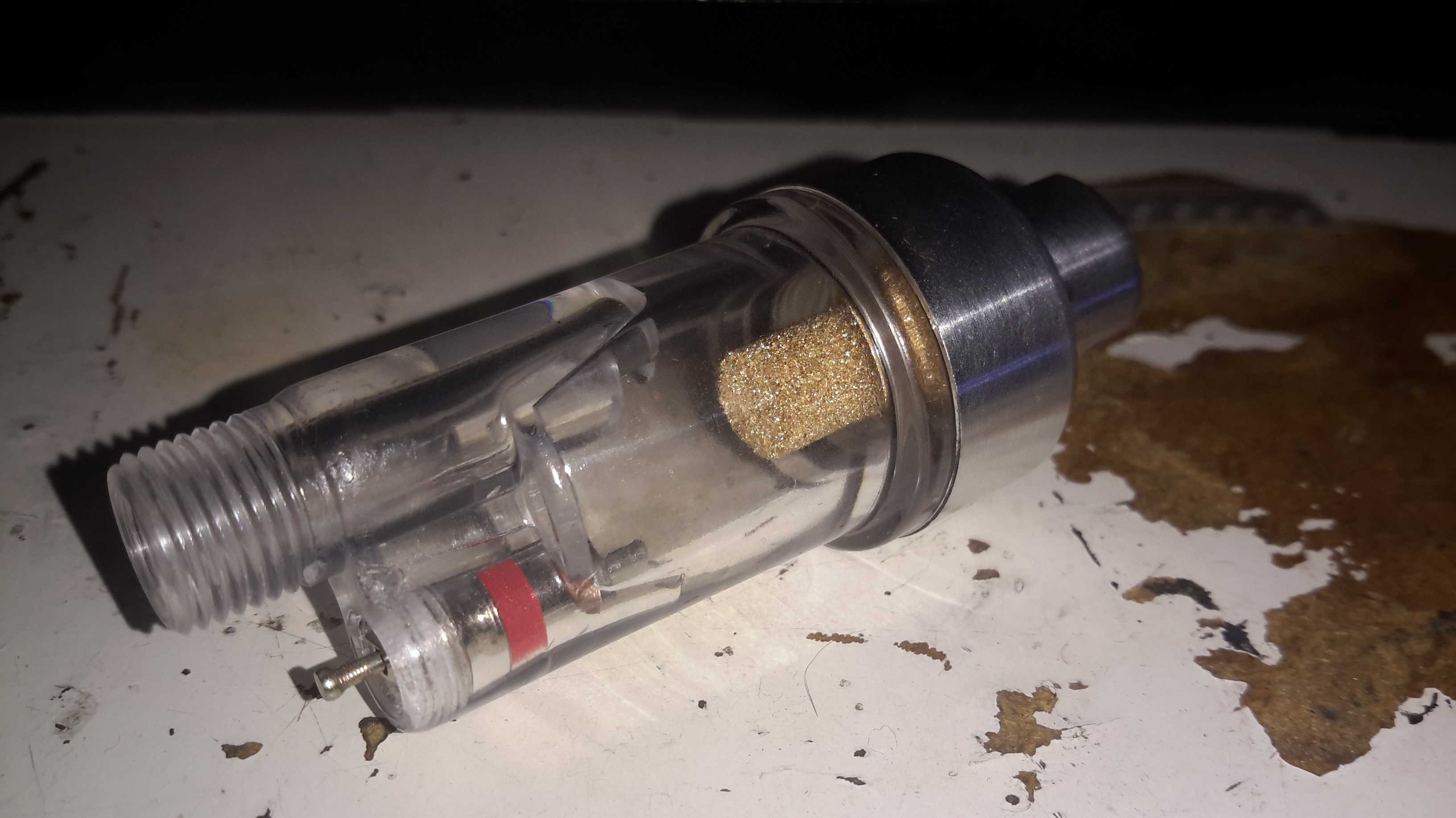
Water Trap
A moisture trap is supplied for the brush, to prevent water drops being sprayed out with the paint. Very handy.
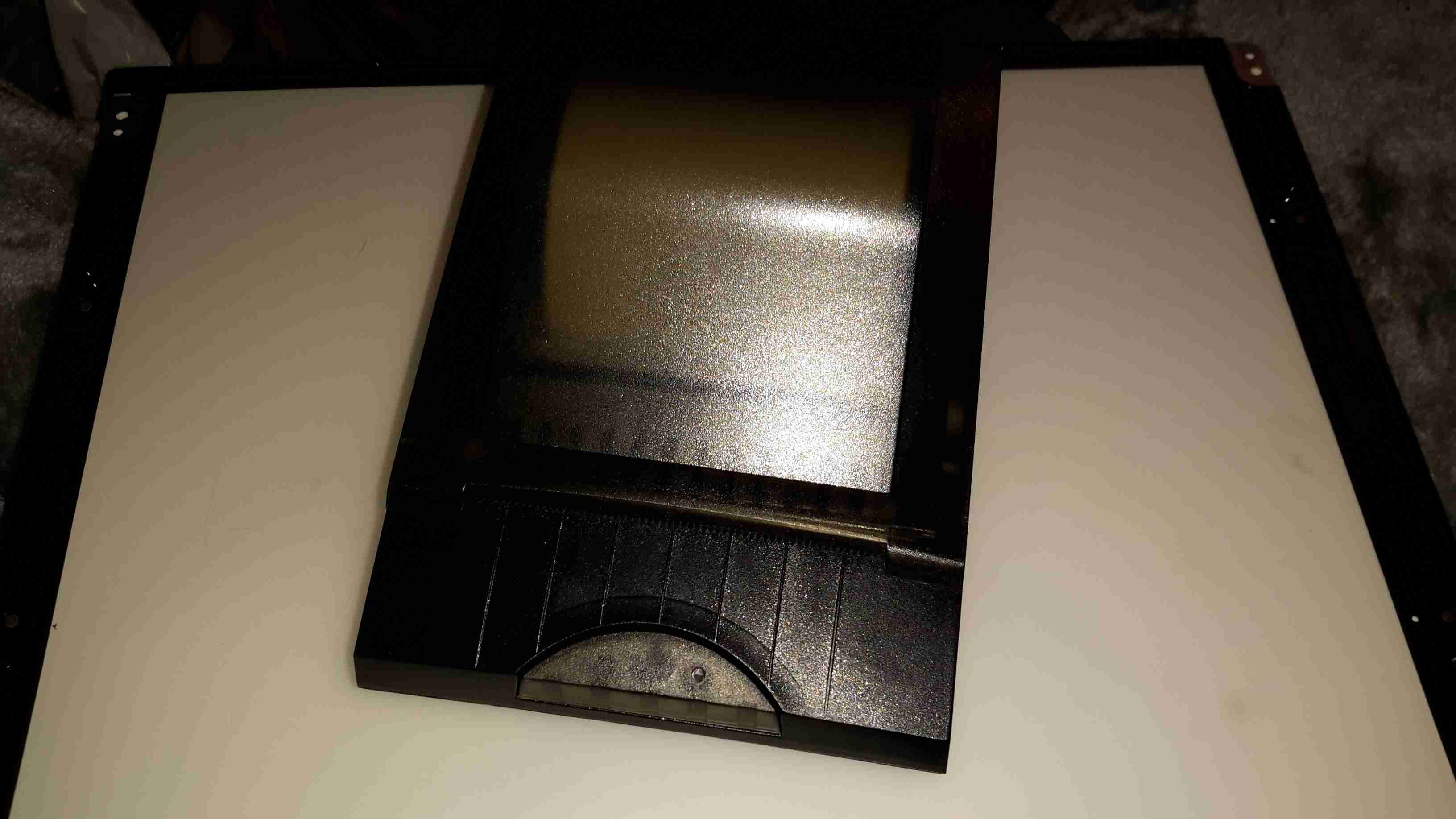
I have yet another receipt printer, this one appears to be brand new. It’s possibly the smallest thermal 80mm printer I have at the moment, and has both USB & Serial interfaces.
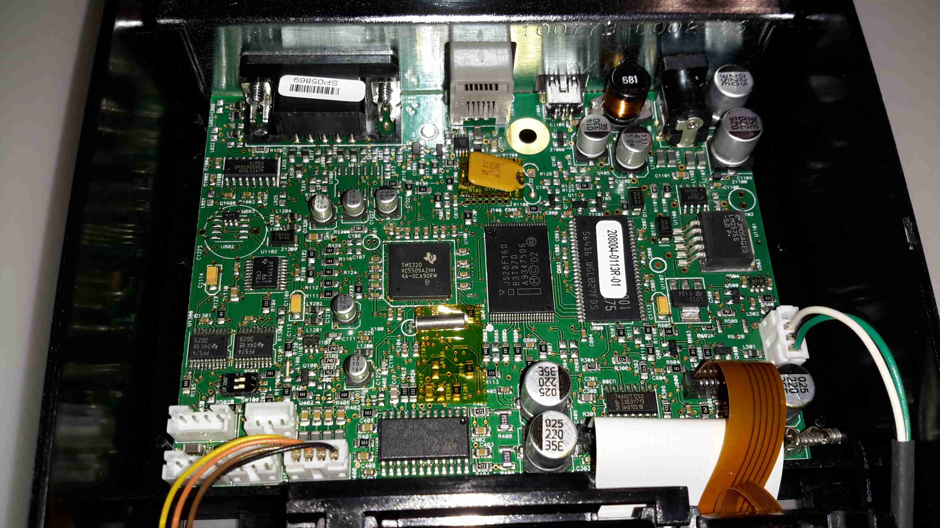
Controller PCB
There’s not much to these printers at all. Removing a single screw allows the case halves to separate, showing the guts. The controller is based around a Texas Instruments TMS320VC5509AFixed-Point DSP. It’s associated Flash ROM & RAM are to the right.
Power supply is dealt with in the top right of the PCB, with the interface ports further left.
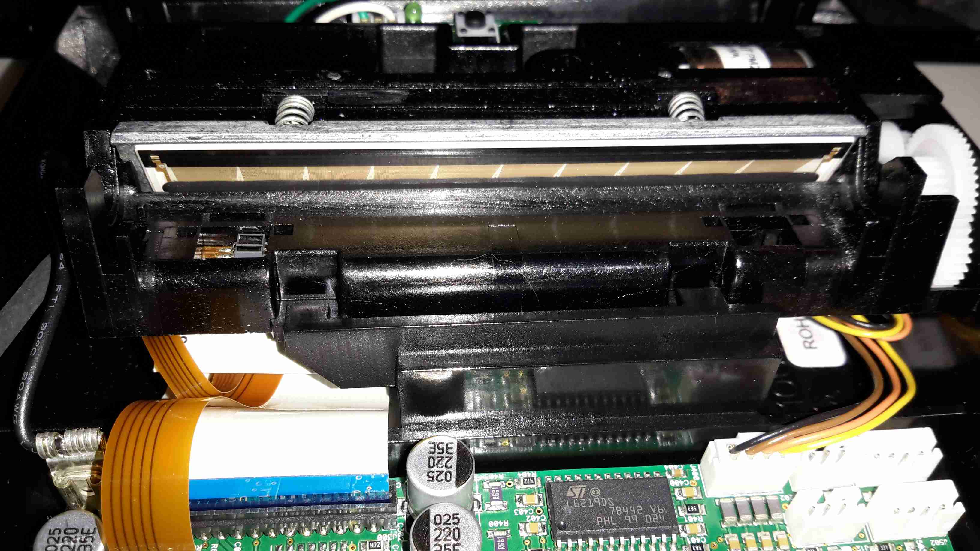
Print Head
Here’s the thermal mechanism itself, with the large print head. The stepper motor to drive the paper through the printer is just peeking out at top right. The paper present sensor is just under the left hand side of the print head.
In the past, I’ve used RC type LiPo packs for my mobile power requirements, but these tend to be a bit bulky, since they’re designed for very high discharge current capability – powering large motors in models is a heavy job.
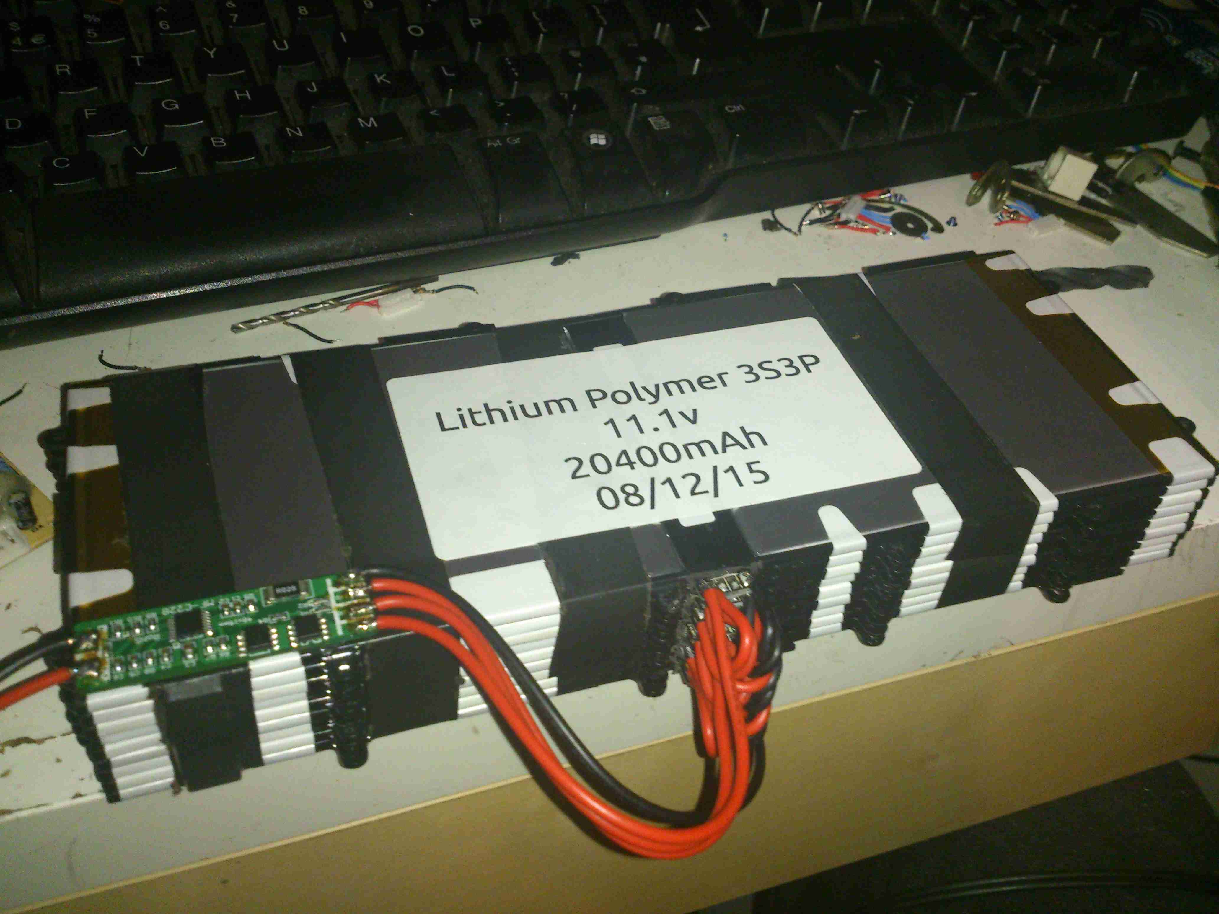
I recently came across some Samsung Galaxy Tab 10.1 battery packs on eBay very cheaply, at £2.95 a piece. For this price I get 6800mAh of capacity at 4.2v, for my 12v requirements, 3 packs must be connected in series, for a total output of 12.6v fully charged.
For an initial pack, I got 9 of these units, to be connected in 3 sets of 3 to make 20Ah total capacity.There are no control electronics built into these batteries – it’s simply a pair of 3400mAh cells connected in parallel through internal polyfuses, and an ID EEPROM for the Tab to identify the battery.
This means I can just bring the cell connections together with the original PCB, without having to mess with the welded cell tabs.
Battery Pack
Here’s the pack with it’s cell connections finished & a lithium BCM connected. This chemistry requires close control of voltages to remain stable, and with a pack this large, a thermal runaway would be catastrophic.
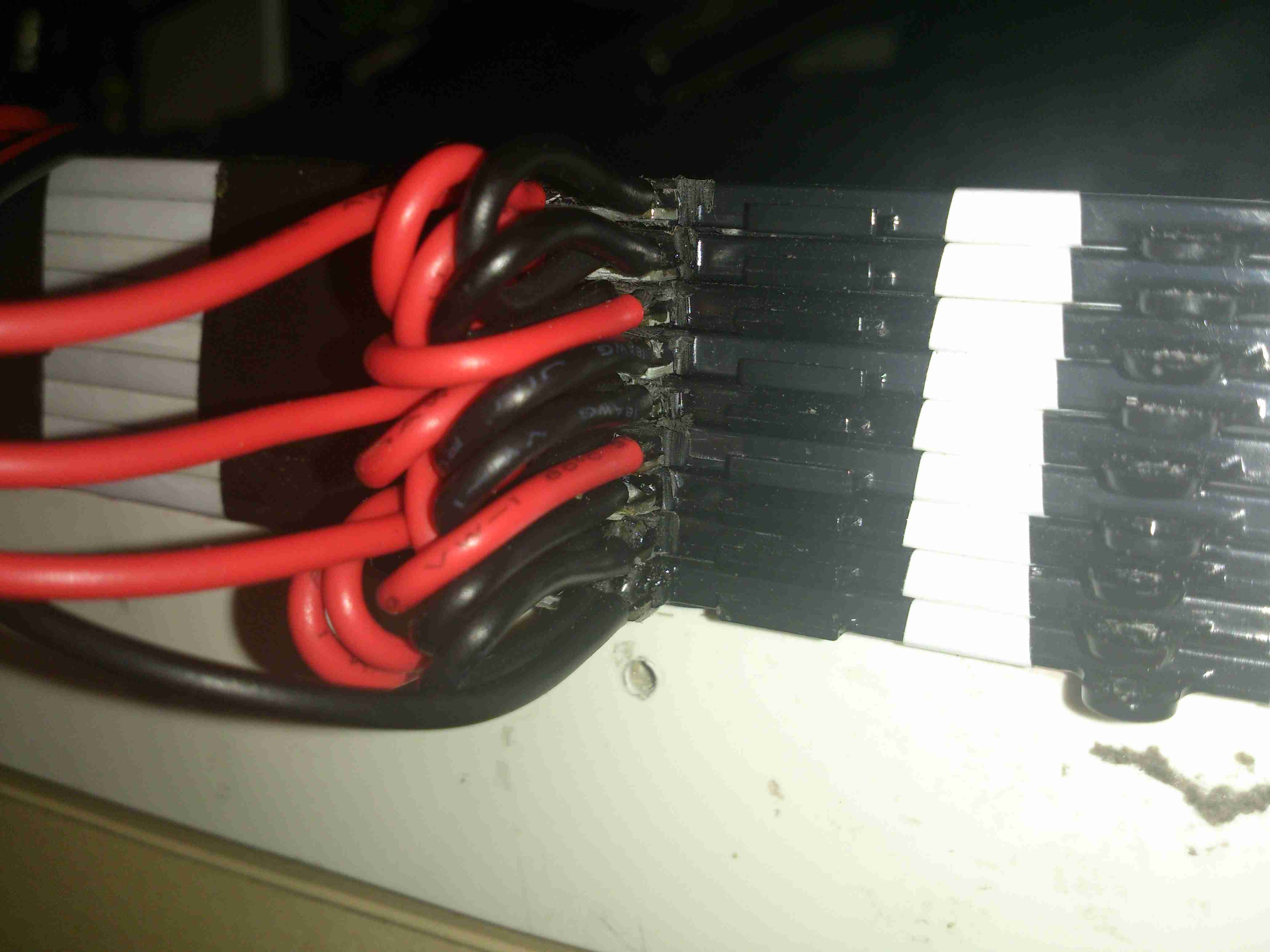
Cell Links
The OEM battery connector has been removed, and my series-parallel cell connections are soldered on, with extra lead-outs for balancing the pack. This was the most time-consuming part of the build.
If all goes well with the life of this pack for utility use, I’ll be building another 5 of these, for a total capacity of 120Ah. This will be extremely useful for portable use, as the weight is about half that of an equivalent lead-acid.
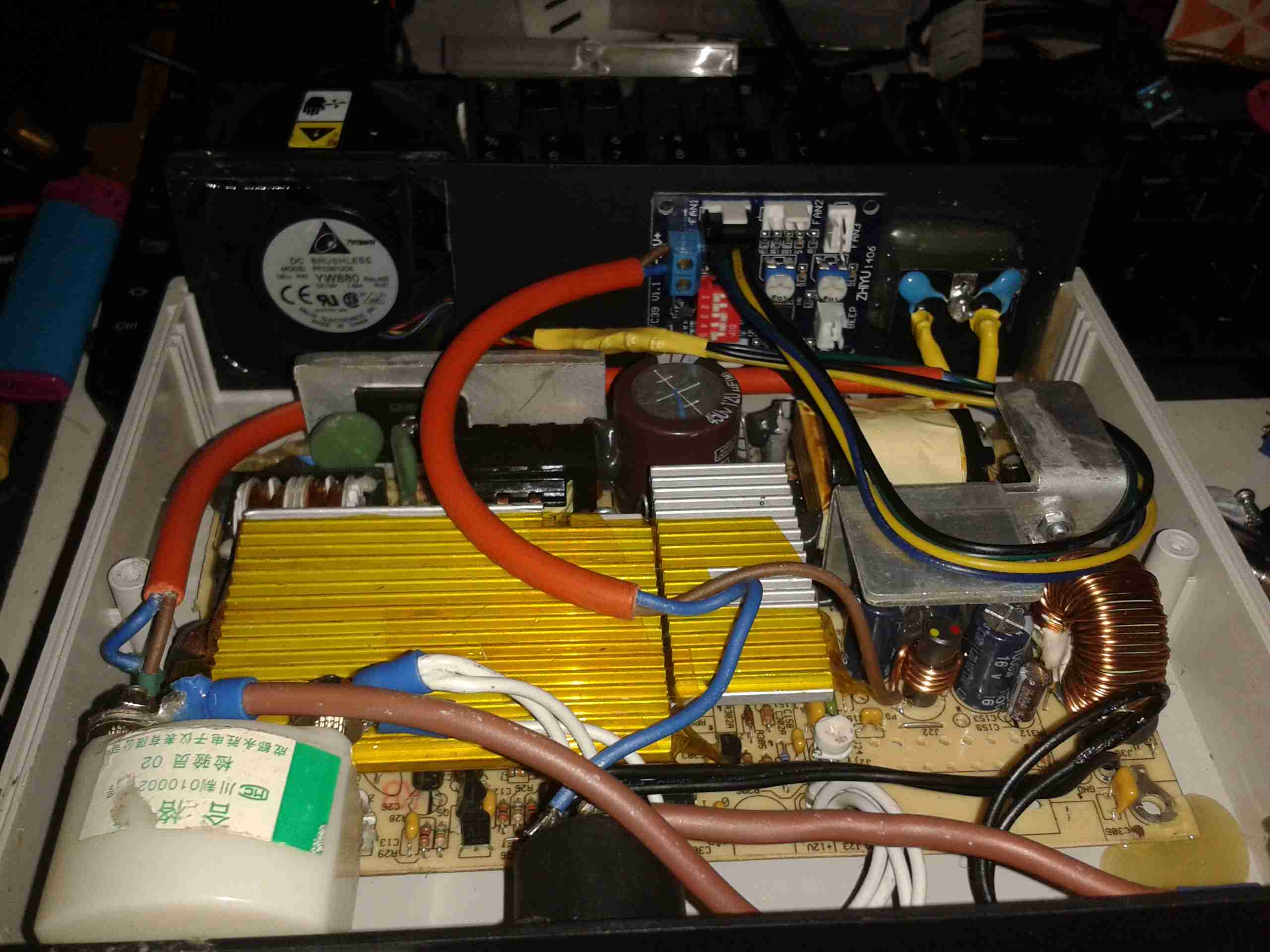
Now the controllers have arrived, I can rejig the supplies to have proper thermal control on their cooling.
Changes Overview
Here’s the top off the PSU. The board has been added to the back panel, getting it’s 12v supply from the cable that originally fed the fan directly. Luckily there was just enough length on the temperature probe to fit it to the output rectifier heatsink without modification.
To connect to the standard 4-pin headers on the controller, I’ve spliced on a PC fan extension cable, as these fans spent their previous lives in servers, with odd custom connectors.
Fan Controller
Here’s the controller itself, the temperature probe is inserted between the main transformer & the rectifier heatsink.
I’ve set the controller to start accelerating the fan at 50°C, with full speed at 70°C.
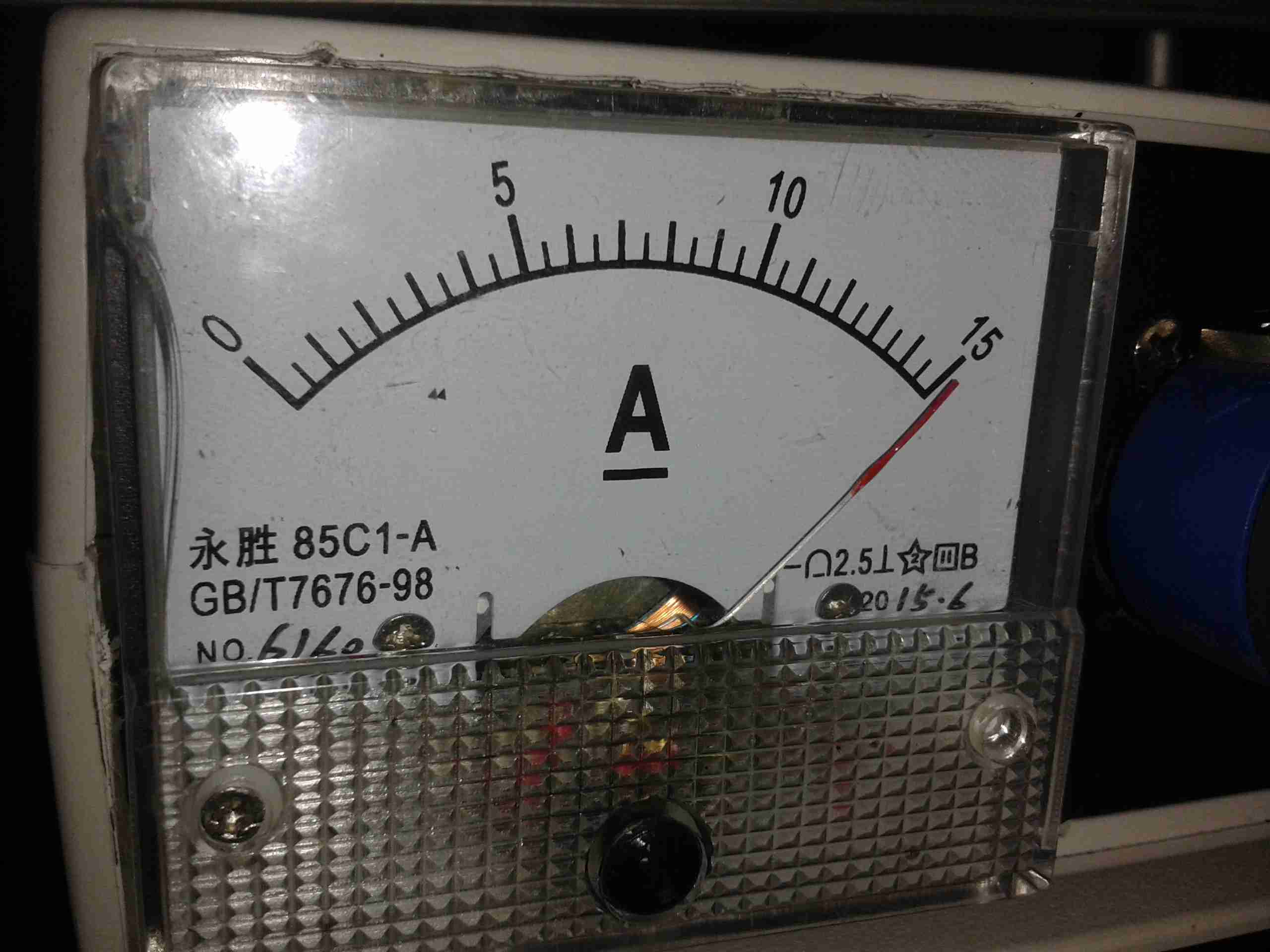
Full Load Test
Under a full load test for 1 hour, the fan didn’t even speed up past about 40% of full power. The very high airflow from these fans is doing an excellent job of keeping the supply cool. Previously the entire case was very hot to the touch, now everything is cool & just a hint of warm air exits the vents. As the fan never runs at full speed, the noise isn’t too deafening, and immediately spools back down to minimum power when the load is removed.
The power supplies I have recently built from surplus Cisco switch boards have started displaying a rather irritating problem – continual load of over 9A causes the supplies to shut down on overheat.
This was partially expected, as the original switches that these supplies came from are cooled by a monster of a centrifugal blower that could give a Dyson a run for it’s money. The problem with these fans is that they’re very loud, draw a lot of power (3-4A) and aren’t small enough to fit into the case I’ve used for the project.
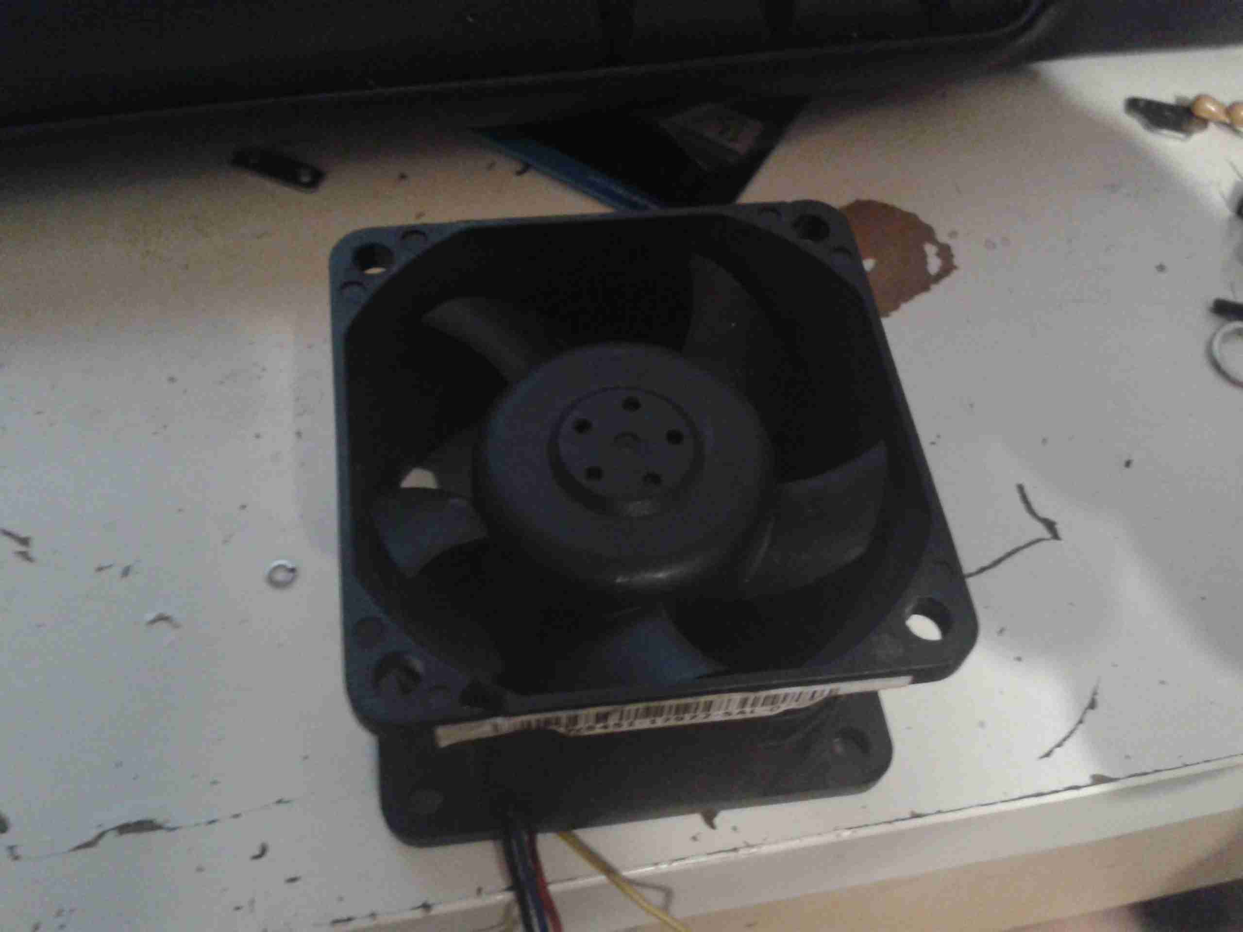
The solution of course, is a bigger fan – I’ve got some Delta AFB0612EHE server fans, these are very powerful axial units, shifting 60CFM at 11,000RPM, with a power draw of 1.12A.
They’re 60mm diameter, so only just fit into the back of the case – although they stick out of the back by 40mm.
Monster Fan
Here’s the fan, not the beefiest I have, but the beefiest that will fit into the available space.
These will easily take fingers off if they get too close at full speed, so guards will definitely be required.
To reduce the noise (they sound like jet engines at full pelt), I have ordered some PWM controllers that have a temperature sensor onboard, so I can have the fan run at a speed proportional to the PSU temperature. I will probably attach the sensor to the output rectifier heatsink, since that’s got the highest thermal load for it’s size.
This is the teardown of a Zebra P330i plastic card printer, used for creating ID cards, membership cards, employee cards, etc. I got this as a faulty unit, which I will detail later on.
This printer supports printing on plastic cards from 1-30mils thick, using dye sublimation & thermal transfer type printing methods. Interfaces supplied are USB & Ethernet. The unit also has the capability to be fitted with a mag stripe encoder & a smart card encoder, for extra cost.
Print Engine
On the left here is the print engine open, the blue cartridge on the right is a cleaning unit, using an adhesive roller to remove any dirt from the incoming card stock.
This is extremely important on a dye sublimation based printing engine as any dirt on the cards will cause printing problems.
Cards In Feeder
Here on the right is the card feeder unit, stocked with cards. This can take up to 100 cards from the factory.
The blue lever on the left is used to set the card thickness being used, to prevent misfeeds. There is a rubber gate in the intake port of the printer which is moved by this lever to stop any more than a single card from being fed into the print engine at any one time.
Card Feeder Belt
Here is the empty card feeder, showing the rubber conveyor belt. This unit was in fact the problem with the printer, the drive belt from the DC motor under this unit was stripped, preventing the cards from feeding into the printer.
Print Head
Here is a closeup of the print head assembly. The brown/black stripe along the edge is the row of thin-film heating elements. This is a 300DPI head.
Print Station
This is under the print head, the black roller on the left is the platen roller, which supports the card during printing. The spool in the center of the picture is the supply spool for the dye ribbon.
In the front of the black bar in the bottom center, is a two-colour sensor, used to locate the ribbon at the start of the Yellow panel to begin printing.
LCD PCB
Inside the top cover is the indicator LCD, the back of which is pictured right.
This is a 16×1 character LCD from Hantronix. This unit has a parallel interface.
LCD
Front of the LCD, this is white characters on a blue background.
Roller Drive Belts
Here is the cover removed from the printer, showing the drive belts powering the drive rollers. There is an identical arrangement on the other side of the print engine running the other rollers at the input side of the engine.
Mains Filter
Here the back panel has been removed from the entire print engine, complete with the mains input wiring & RFI filtering.
This unit has excellent build quality, just what is to be expected from a £1,200+ piece of industrial equipment.
Main Frame With Motors
The bottom of the print engine, with all the main wiring & PCB removed, showing the main drive motors. The left hand geared motor operates the head lift, the centre motor is a stepper, which operates the main transmission for the cards. The right motor drives the ribbon take up spindle through an O-Ring belt.
Feeder Drive Motor
Card feeder drive motor, this connects to the belt assembly through a timing belt identical to the roller drive system.
All these DC geared motors are 18v DC, of varying torque ratings.
Power Supply
Here is the main power supply, a universal input switch-mode unit, outputting 24v DC at 3.3A.
PSU Label
PSU info. This is obviously an off the shelf unit, manufactured by Hitek. Model number FUEA240.
Print Engine Rear
The PSU has been removed from the back of the print engine, here is shown the remaining mechanical systems of the printer.
Print Engine Components
A further closeup of the print engine mechanical bay, the main stepper motor is bottom centre, driving the brass flywheel through another timing belt drive. The O-Ring drive on the right is for the ribbon take up reel, with the final motor driving the plastic cam on the left to raise/lower the print head assembly.
The brass disc at the top is connected through a friction clutch to the ribbon supply reel, which provides tension to keep it taut. The slots in the disc are to sense the speed of the ribbon during printing, which allows the printer to tell if there is no ribbon present or if it has broken.
RFID PCB
Here is a further closeup, showing the RFID PCB behind the main transmission. This allows the printer to identify the ribbon fitted as a colour or monochrome.
The antenna is under the brass interrupter disc on the left.
I/O Daughterboard
The I/O daughterboard connects to the main CPU board & interfaces all the motors & sensors in the printer.
Main PCB
Here is the main CPU board, which contains all the logic & processing power in the printer.
CPU
Main CPU. This is a Freescale Semiconductor part, model number MCF5206FT33A, a ColdFire based 32-bit CPU. Also the system ROM & RAM can be seen on the right hand side of this picture.
Ethernet Interface
Bottom of the Ethernet interface card, this clearly has it’s own RAM, ROM & FPGA. This is due to this component being a full Parallel interface print server.
Ethernet Interface Top
Top of the PCB, showing the main processor of the print server. This has a ferrite sheet glued to the top, for interference protection.
Here is a label maker, bought on offer at Maplin Electronics. Full Qwerty keyboard with 1 line dot matrix LCD display visible here. Power is 4 AAA cells or a 6v DC Adaptor.
Rear
Rear cover removed. Battery compartment is on the left hand side, space for the tape cartridge on the right. Ribbon cable leading to the thermal print head is on the far right, with rubber tape drive roller.
PCB
PCB under the top cover with the main CPU, a MN101C77CBM from Panasonic. This CPU features 48K Mask ROM & 3K of RAM. Max clock frequency is 20MHz. 32kHz clock crystal visible underneath a Rohm BA6220 Electronic speed controller IC.
This is used to drive the printer motor at a constant accurate speed, to feed the tape past the thermal head. Miniature potentiometer adjusts speed.
Ribbon cable at the bottom of the board connects to the print head, various wiring at the left connects to the battery & DC Jack.
Printer Drive
Printer drive mechanism. Small DC motor drives the pinch roller though a gear train. DC Jack & reverse polarity protection diode is on the right.
This unit uses a centre negative DC jack, which is unusual.
Cartridge
Thermal tape cartridge, black text on white background.
Here are the internals of a cheap Microwave/Convection Oven combo. Electronics bay is pretty much the same as a standard microwave, with the magnetron, transformer & diode/capacitor voltage doubler, with the addition of an extra fan & a pair of nichrome elements to provide the convection oven function.
Convection Fan
Convection blower which keeps the cooking vapours & smoke away from the elements, & circulates the hot air around the cooking chamber. This is a 12v DC centrifugal type blower.
Convection Element
The elements are inside this steel shield, air duct extends from the centre.
Thermal Cutouts
This oven has a pair of thermal switches on the magnetron.
Capacitor & Diode
The usual capacitor/diode voltage doubler in the magnetron power supply. The transformer is visible to the left.
Controller
Electronic controller PCB. This has a pair of relays that switch the elements & the magnetron transformer.
Here is a cheap no brand hot laminator. This pulls the paper, inside a plastic pouch through a pair of heated rollers to seal it.
Heater
Top removed, heater assembly visible. PCB attached to the top cover holds LEDs to indicate power & ready status.
SwitchThermostat
Here is the thermostat & thermal fuse, the thermostat switching the indicator on the front panel to tell the user when the unit is up to temperature. This has a self regulating thermostat. Thermal fuse inside the heat resistant tubing is to protect against any failure of the heater.
Motor
5 RPM motor that turns the rollers through a simple gear system.
Here’s my prototype 455nm laser head, constructed from the front section of an Aixiz module threaded into a heatsink from an old ATX power supply. This sink has enough thermal mass for short 1W testing.
Connection
Connection to the laser diode at the back of the heatsink. Cable is heat shrink covered for strain relief, & hot glued to the sink for extra strain relief.
Beamshot 1
Looking down the beam, laser is under the camera. Operating around 1.2W here
Beamshot 2
Camera looking towards the laser. Again operating at ~1.2W output power.
Here is a Bosch 14.4v Professional cordless drill/driver, recovered from a skip!
It was thrown away due to a gearbox fault, which was easy to rectify.
Internals
Here is the drill with the side cover removed, showing it’s internal parts. The speed controller is below the motor & gearbox here. The unit at the top consists of a 12v DC motor, coupled to a 4-stage epicyclic gearbox unit, from which can be selected 2 different ratios, by way of the lever in the centre of the box. This disables one of the gear stages. There is a torque control clutch at the chuck end of the gearbox, this was faulty when found.
Motor
Here is the drive motor disconnected from the gearbox, having a bayonet fitting on the drive end.
Drive Gear
This is the primary drive gear of the motor, which connects with the gearbox.
Cooling Fan
The motor is cooled by this fan inside next to the commutator, drawing air over the windings.
Gearbox
This is the gearbox partially disassembled, showing the 1st & second stages of the geartrain. The second stage provides the 2 different drive ratios by having the annulus slide over the entire gearset, disabling it entirely, in high gear. The annulus gears are a potential weak point in this gearbox, as they are made from plastic, with all other gears being made of steel.
Charger
Here is the charging unit for the Ni-Cd battery packs supplied with the drill. The only indicator is the LED shown here on the front of the unit, which flashes while charging, & comes on solid when charging is complete. Charge termination is by way of temperature monitoring.
Transformer
Here the bottom of the charger has been removed, showing the internal parts. An 18v transformer supplies power to the charger PCB on the left.
Charger PCB
This is the charger PCB, with a ST Microelectronics controller IC marked 6HKB07501758. I cannot find any information about this chip.
Battery Pack Internals
Here is a battery pack with the top removed, showing the cells.
Temperature Sensor
This is the temperature sensor embedded inside the battery pack that is used by the charger to determine when charging is complete.
This is a 1500W hairdryer, death caused by thermal switch failure.
Switch
This is the switch unit. Attached are two suppression capacitors & a blocking diode. Cold switch is on right.
Heating Element
Heating element unit removed from housing. Coils of Nichrome wire heat the air passing through the dryer. Fan unit is on right.
Thermal Switch
Other side of the heating element unit, here can be seen the thermal switch behind the element winding. (Black square object).
Fan Motor
The fan motor in this dryer is a low voltage DC unit, powered through a resistor formed by part of the heating element to drop the voltage to around 12-24v. Mounted on the back of the motor here is a rectifier assembly. Guide vanes are visible around the motor, to straighten the airflow from the fan blades.
Fan
5-blade fan forces air through the element at high speed. Designed to rotate at around 13,000RPM.
Tip Jar
If you’ve found my content useful, please consider leaving a donation by clicking the Tip Jar below!
All collected funds go towards new content & the costs of keeping the server online.