While I was already well aware of the effects of petrol on silicone products – the stuff swells up & dissolves over a very short period of time, which makes it an unsuitable material for seals in a petrol fuel system.
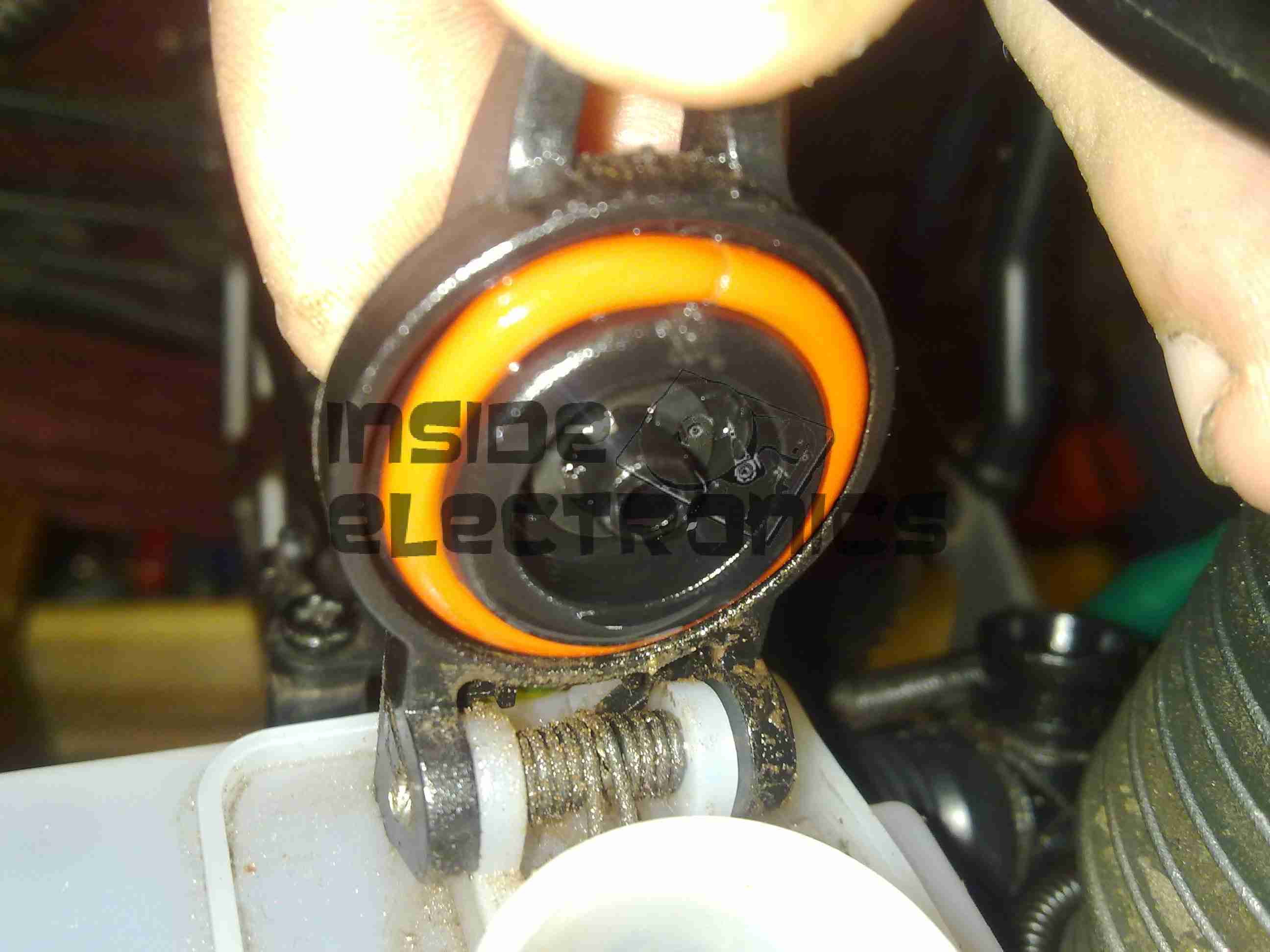
Fuel Tank Cap Seal
I wasn’t aware the O-Ring on the fuel tank cap of the Savage is silicone, as can be seen in the image above it has swelled up to much larger than it’s original size. It’s supposed to sit in the groove on the cap & fit into the filler neck when closed.
This was only from a couple of hours of petrol exposure, now the seal is such an ill fit that the cap will not close properly.
The solution here is to replace the ring with a Viton O-Ring, 2.5mm cross section, 23mm ID. I assume the fuel tank is made of polypropylene – this should stand up fine to the new fuel.
Another concern was the O-Rings on the carburettor needles, however these seem to be made of a petrol-resistant material already & are showing no signs of deterioration after 24+ hours of fuel immersion.
The O-Rings that seal the engine backplate to the crankcase also seem to be working fine with the new fuel.
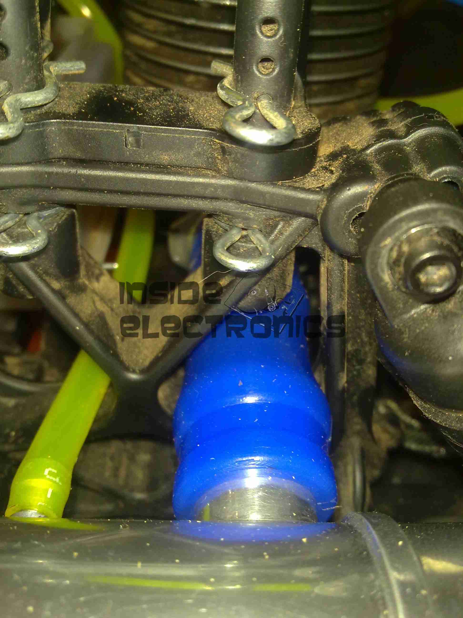
Another silicone part on the engine is the exhaust coupling, between the back of the cylinder & the silencer, I’m not aware of a suitable replacement as yet, although as it will mainly be exposed to the combustion products & not raw fuel, it may just survive the task.
Exhaust Coupling
The extra heat from burning petrol in one of these engines may also put a lot of stress on this component, if it eventually fails I may attempt a replacement with automotive hose – time will tell on this one.
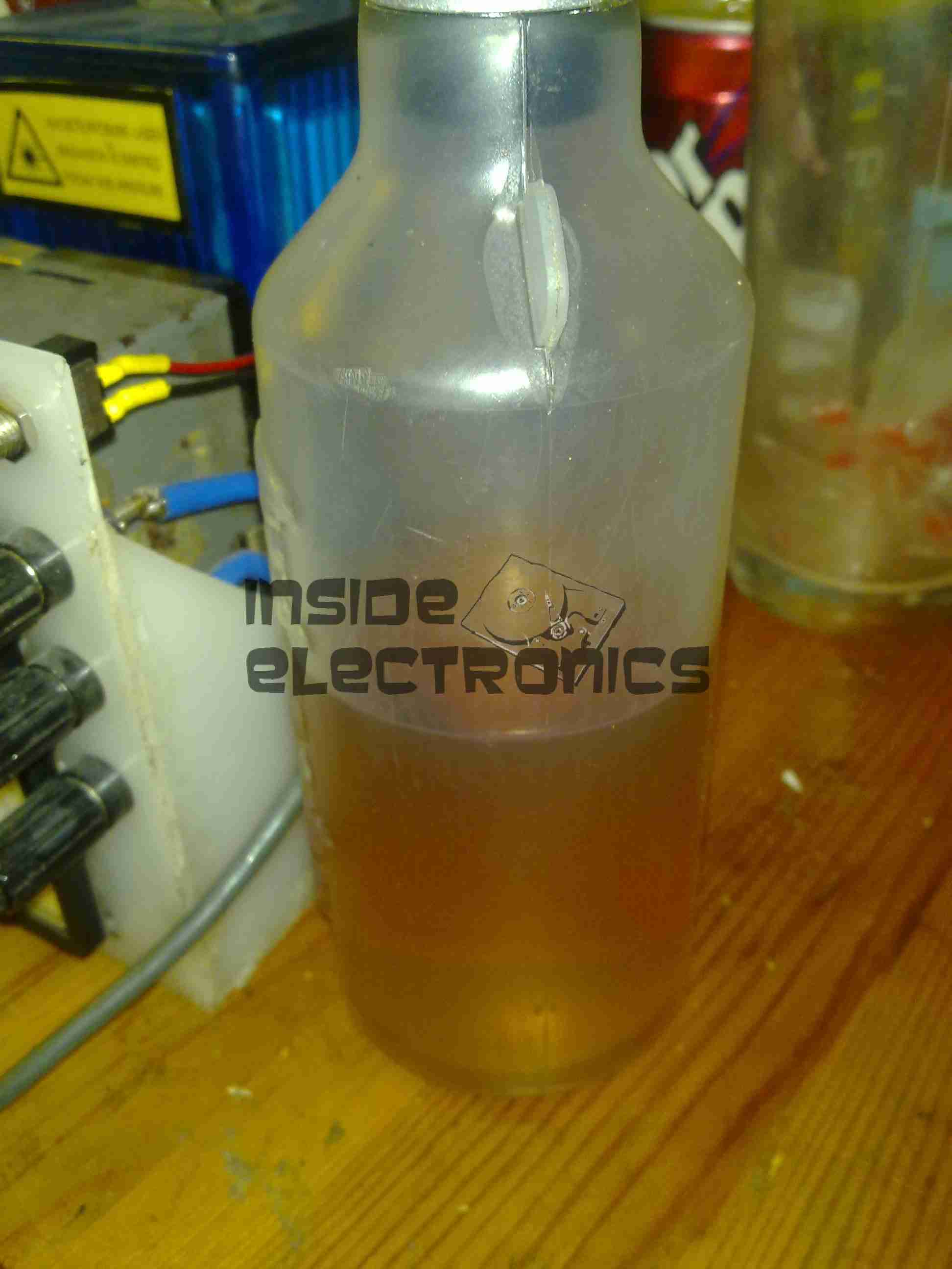
Fuel Bottle
I’m also not sure of the plastic that standard fuel bottles are made from – their resin identification number is 7, so it could be any special plastic, but I’m guessing it’s Nylon.
However according to the spec sheet for Nylon, it’s chemically compatible with petrol – yet the plastic appears to be getting softer with exposure, so it may be a special blend designed specifically for glow fuel.
Besides these small glitches, the engine is running well on it’s newly assigned diet of petrol, I’m currently running an 18:1 mix of petrol to oil (250ml oil to 4.5L of petrol), this seems to be providing more than adequate lubrication. While it smokes like a chimney, plenty of unburned oil is making it out of the exhaust, so the engine’s internals should have a liberal coating.
I’m yet to actually run the model out in open space so I can start tuning the mixture, but bench tests are promising.
This is the teardown of a Zebra P330i plastic card printer, used for creating ID cards, membership cards, employee cards, etc. I got this as a faulty unit, which I will detail later on.
This printer supports printing on plastic cards from 1-30mils thick, using dye sublimation & thermal transfer type printing methods. Interfaces supplied are USB & Ethernet. The unit also has the capability to be fitted with a mag stripe encoder & a smart card encoder, for extra cost.
Print Engine
On the left here is the print engine open, the blue cartridge on the right is a cleaning unit, using an adhesive roller to remove any dirt from the incoming card stock.
This is extremely important on a dye sublimation based printing engine as any dirt on the cards will cause printing problems.
Cards In Feeder
Here on the right is the card feeder unit, stocked with cards. This can take up to 100 cards from the factory.
The blue lever on the left is used to set the card thickness being used, to prevent misfeeds. There is a rubber gate in the intake port of the printer which is moved by this lever to stop any more than a single card from being fed into the print engine at any one time.
Card Feeder Belt
Here is the empty card feeder, showing the rubber conveyor belt. This unit was in fact the problem with the printer, the drive belt from the DC motor under this unit was stripped, preventing the cards from feeding into the printer.
Print Head
Here is a closeup of the print head assembly. The brown/black stripe along the edge is the row of thin-film heating elements. This is a 300DPI head.
Print Station
This is under the print head, the black roller on the left is the platen roller, which supports the card during printing. The spool in the center of the picture is the supply spool for the dye ribbon.
In the front of the black bar in the bottom center, is a two-colour sensor, used to locate the ribbon at the start of the Yellow panel to begin printing.
LCD PCB
Inside the top cover is the indicator LCD, the back of which is pictured right.
This is a 16×1 character LCD from Hantronix. This unit has a parallel interface.
LCD
Front of the LCD, this is white characters on a blue background.
Roller Drive Belts
Here is the cover removed from the printer, showing the drive belts powering the drive rollers. There is an identical arrangement on the other side of the print engine running the other rollers at the input side of the engine.
Mains Filter
Here the back panel has been removed from the entire print engine, complete with the mains input wiring & RFI filtering.
This unit has excellent build quality, just what is to be expected from a £1,200+ piece of industrial equipment.
Main Frame With Motors
The bottom of the print engine, with all the main wiring & PCB removed, showing the main drive motors. The left hand geared motor operates the head lift, the centre motor is a stepper, which operates the main transmission for the cards. The right motor drives the ribbon take up spindle through an O-Ring belt.
Feeder Drive Motor
Card feeder drive motor, this connects to the belt assembly through a timing belt identical to the roller drive system.
All these DC geared motors are 18v DC, of varying torque ratings.
Power Supply
Here is the main power supply, a universal input switch-mode unit, outputting 24v DC at 3.3A.
PSU Label
PSU info. This is obviously an off the shelf unit, manufactured by Hitek. Model number FUEA240.
Print Engine Rear
The PSU has been removed from the back of the print engine, here is shown the remaining mechanical systems of the printer.
Print Engine Components
A further closeup of the print engine mechanical bay, the main stepper motor is bottom centre, driving the brass flywheel through another timing belt drive. The O-Ring drive on the right is for the ribbon take up reel, with the final motor driving the plastic cam on the left to raise/lower the print head assembly.
The brass disc at the top is connected through a friction clutch to the ribbon supply reel, which provides tension to keep it taut. The slots in the disc are to sense the speed of the ribbon during printing, which allows the printer to tell if there is no ribbon present or if it has broken.
RFID PCB
Here is a further closeup, showing the RFID PCB behind the main transmission. This allows the printer to identify the ribbon fitted as a colour or monochrome.
The antenna is under the brass interrupter disc on the left.
I/O Daughterboard
The I/O daughterboard connects to the main CPU board & interfaces all the motors & sensors in the printer.
Main PCB
Here is the main CPU board, which contains all the logic & processing power in the printer.
CPU
Main CPU. This is a Freescale Semiconductor part, model number MCF5206FT33A, a ColdFire based 32-bit CPU. Also the system ROM & RAM can be seen on the right hand side of this picture.
Ethernet Interface
Bottom of the Ethernet interface card, this clearly has it’s own RAM, ROM & FPGA. This is due to this component being a full Parallel interface print server.
Ethernet Interface Top
Top of the PCB, showing the main processor of the print server. This has a ferrite sheet glued to the top, for interference protection.
This is the hydraulic system from an Audi TT that would power the soft top. Here is the hydraulic pump unit. Oil Tank is on the left. Power is 12v DC at ~20A
Cylinders
The pair of hydraulic cylinders that attached to the roof mechanism.
Limit Switch
One of the cylinders has a limit switch built in. The brass bolt coming out of the side of the head is one contact. The other contact is the cylinder body.
Hose
Marking on the hoses. This is Parker Polyflex hydraulic hose. 1/8″ ID.
Motor
Drive motor for the hydraulic pump. Standard DC permanent magnet motor.
Motor Suppression
Motor power terminals & suppression capacitors. As the reversing relays actually short the motor out when de-energized, there is a lot of arcing at the brushes without some suppression.
Reversing Relays
Reversing relay stack. Each relay is a SPDT configuration. The pair are arranged as a DPDT bank to reverse the motor, depending on which relay is energized.
Tank
Detail of the oil tank showing the level markings.
Power Valve
Solenoid valve on top of the unit. This valve provides full pump pressure to the cylinders when energized.
Tip Jar
If you’ve found my content useful, please consider leaving a donation by clicking the Tip Jar below!
All collected funds go towards new content & the costs of keeping the server online.