Posted on Leave a comment

HPI Savage Petrol Conversion – Fuel & Silicone – Chemical Compatibility

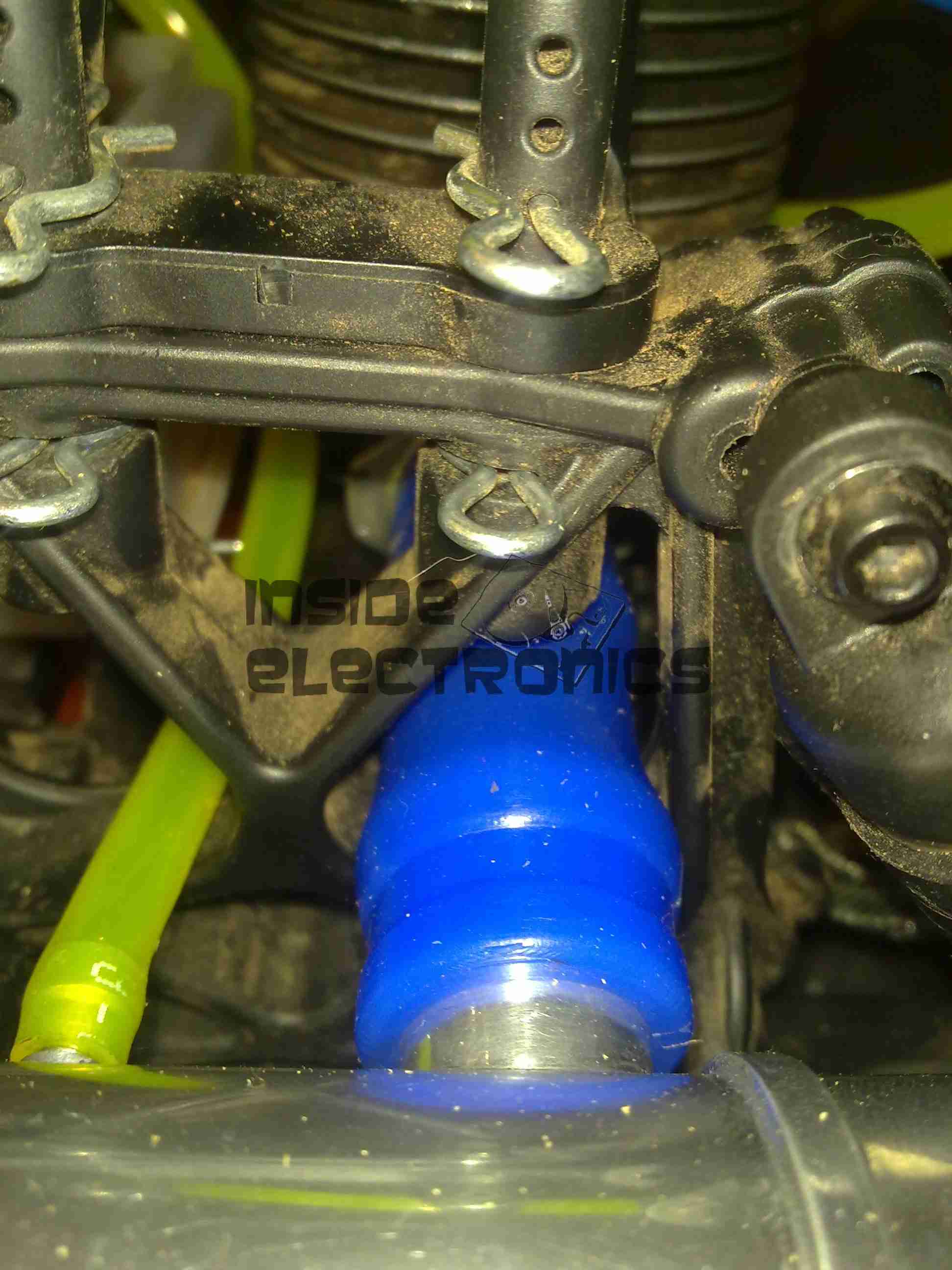
While I was already well aware of the effects of petrol on silicone products – the stuff swells up & dissolves over a very short period of time, which makes it an unsuitable material for seals in a petrol fuel system.

Fuel Tank Cap Seal
Fuel Tank Cap Seal

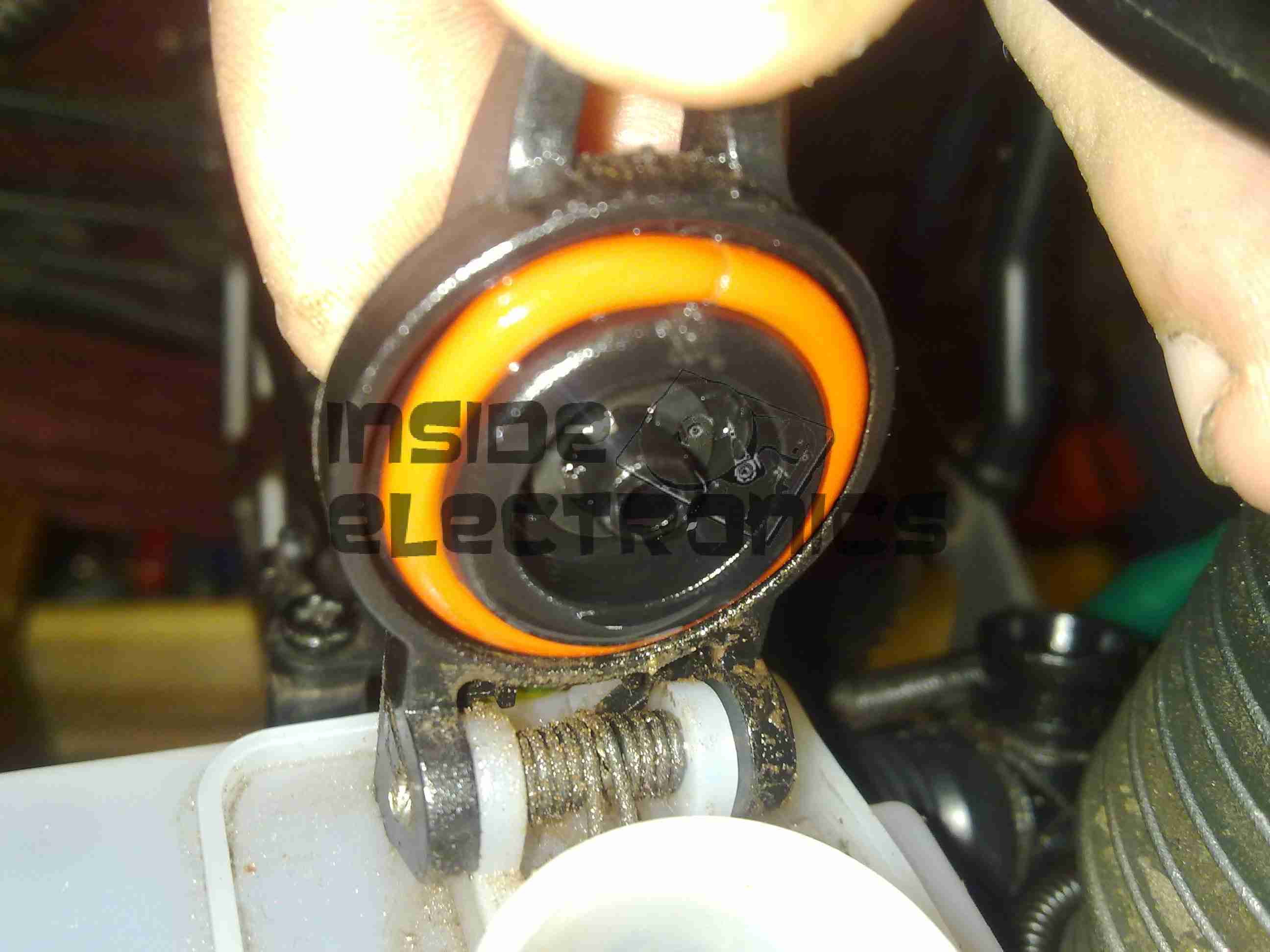
I wasn’t aware the O-Ring on the fuel tank cap of the Savage is silicone, as can be seen in the image above it has swelled up to much larger than it’s original size. It’s supposed to sit in the groove on the cap & fit into the filler neck when closed.
This was only from a couple of hours of petrol exposure, now the seal is such an ill fit that the cap will not close properly.

The solution here is to replace the ring with a Viton O-Ring, 2.5mm cross section, 23mm ID. I assume the fuel tank is made of polypropylene – this should stand up fine to the new fuel.

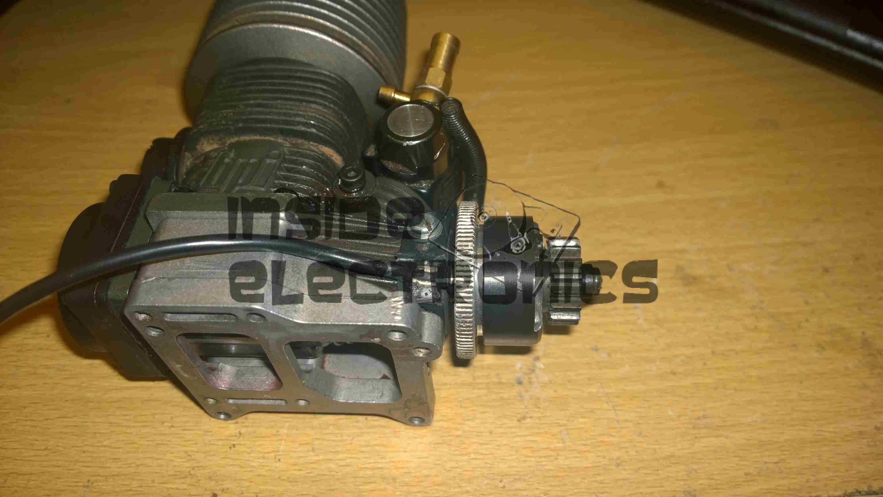
Another concern was the O-Rings on the carburettor needles, however these seem to be made of a petrol-resistant material already & are showing no signs of deterioration after 24+ hours of fuel immersion.
The O-Rings that seal the engine backplate to the crankcase also seem to be working fine with the new fuel.

Another silicone part on the engine is the exhaust coupling, between the back of the cylinder & the silencer, I’m not aware of a suitable replacement as yet, although as it will mainly be exposed to the combustion products & not raw fuel, it may just survive the task.

Exhaust Coupling
Exhaust Coupling

The extra heat from burning petrol in one of these engines may also put a lot of stress on this component, if it eventually fails I may attempt a replacement with automotive hose – time will tell on this one.

Fuel Bottle
Fuel Bottle

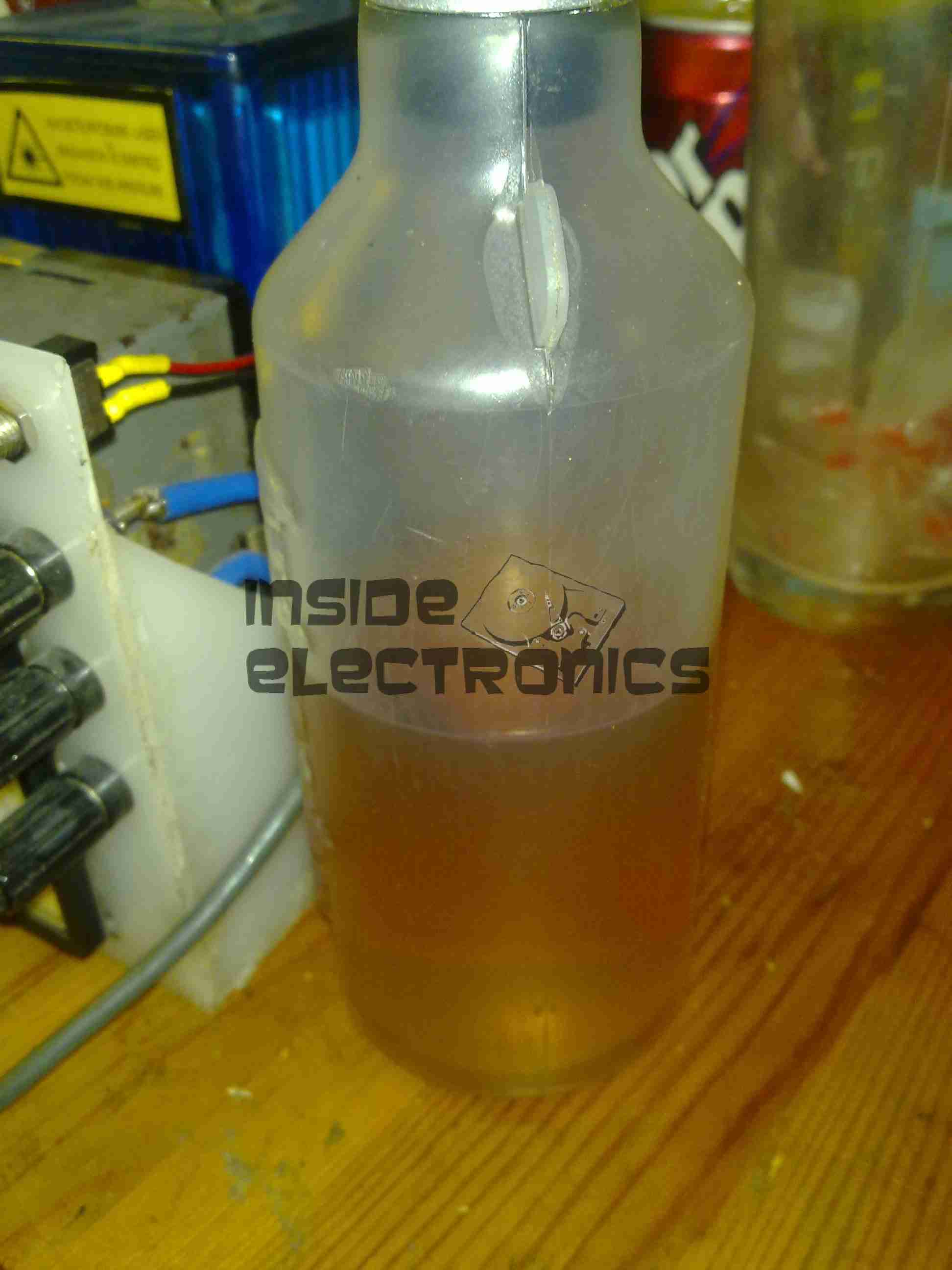
I’m also not sure of the plastic that standard fuel bottles are made from – their resin identification number is 7, so it could be any special plastic, but I’m guessing it’s Nylon.
However according to the spec sheet for Nylon, it’s chemically compatible with petrol – yet the plastic appears to be getting softer with exposure, so it may be a special blend designed specifically for glow fuel.


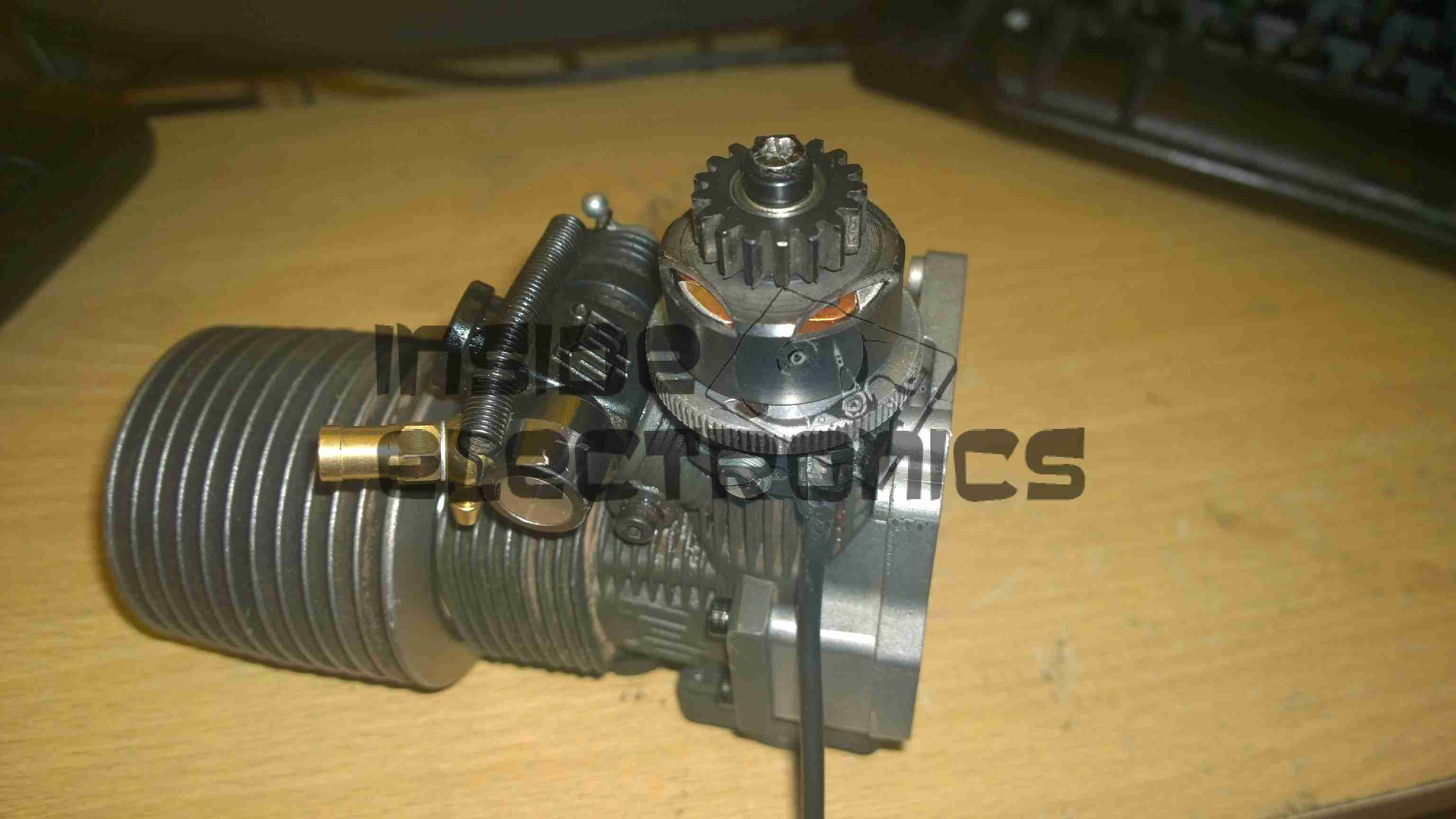
Besides these small glitches, the engine is running well on it’s newly assigned diet of petrol, I’m currently running an 18:1 mix of petrol to oil (250ml oil to 4.5L of petrol), this seems to be providing more than adequate lubrication. While it smokes like a chimney, plenty of unburned oil is making it out of the exhaust, so the engine’s internals should have a liberal coating.
I’m yet to actually run the model out in open space so I can start tuning the mixture, but bench tests are promising.

More to come!

Posted on Leave a comment

HPI Nitrostar F4.6 Ignition Conversion

As there was no other online example of someone converting a glow/nitro car engine onto CDI ignition, I thought I would document the highlights here.
The engine is currently still running on glow fuel, but when the required fuel lines arrive I will be attempting the switch over to 2-Stroke petrol mix. This should definitely save on fuel costs.

The engine in this case is a HPI NitroStar F4.6 nitro engine, from a HPI Savage X monster truck.

F4.6 Engine
F4.6 Engine

Above is the converted engine with it’s timing sensor. As The installation of this was pretty much standard, a complete strip down of the engine was required to allow the drilling & tapping of the two M3x0.5 holes to mount the sensor bracket to. The front crankshaft bearing has to be drifted out of the crankcase for this to be possible.

Ignition Hall Sensor

Detail of the ignition hall sensor. The bracket has to be modified to allow the sensor to face the magnet in the flywheel. Unlike on an Aero engine, where the magnet would be on the outside edge of the prop driver hub, in this case the hole was drilled in the face of the flywheel near the edge & the magnet pressed in. The Hall sensor is glued to the modified bracket with the leads bent to position the smaller face towards the back of the flywheel.
The clearance from the magnet to sensor is approx. 4mm.

Flywheel Magnet
Flywheel Magnet

Detail of the magnet pressed into the flywheel. A 3.9mm hole was drilled from the back face, approx 2mm from the edge, & the magnet pressed into place with gentle taps from a mallet & drift, as I had no vice to hand.
Initial timing was a little fiddly due to the flywheel only being held on with a nut & tapered sleeve, so a timing mark can be made inside the rear of the crankcase, across the crank throw & case to mark the 28 degree BTDC point, the flywheel is then adjusted to make the ignition fire at this point, before carefully tightening the flywheel retaining nut to ensure no relative movement occurs.
The slots in the sensor bracket allow several degrees of movement to fine adjust the timing point once this rough location has been achieved.

1/4"-32 Spark Plug
1/4″-32 Spark Plug

Definitely the tiniest spark plug I’ve ever seen, about an inch long. Some trouble may be encountered with this on some engines – the electrodes stick out about 2mm further into the combustion chamber than a standard glow plug does. This causes the ground electrode to hit the top of the piston crown. (This happens on the HPI NitroStar 3.5 engine). The addition of another copper washer under the plug before tightening should cure this problem.

RcExl CDI Ignition Module

Ignition module. Due to the depth of the plug in the heatsink head on these engines, I will have to modify the plug cap to straighten it out, as it will not fit in this configuration.
However, ignition modules are available from HobbyKing with straight plug caps, this makes modification unnecessary

The ignition & components used on this system were obtained from JustEngines.