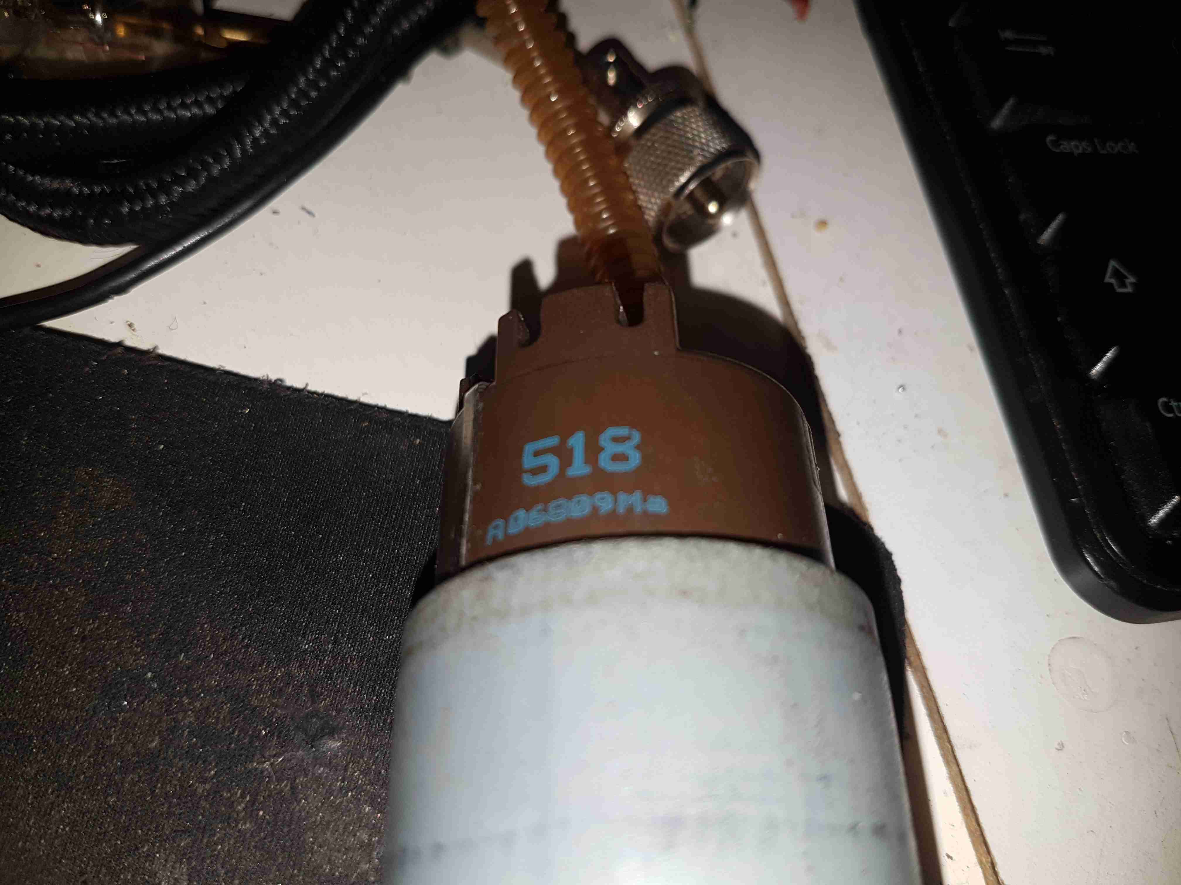
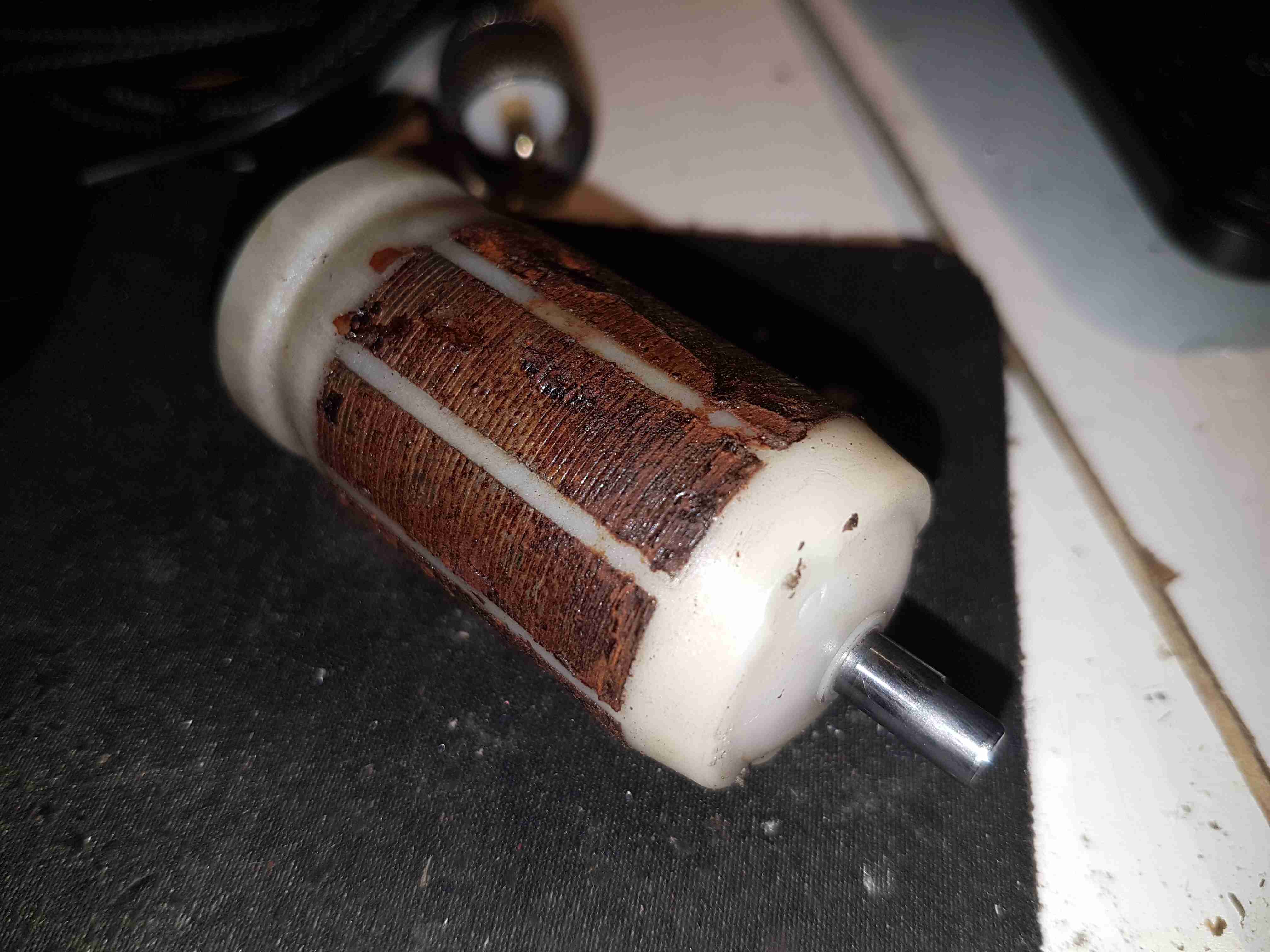
Here’s a destructive teardown of an automotive in-tank turbine fuel pump, used on modern Petrol cars. These units sit in the tank fully immersed in the fuel, which also circulates through the motor inside for cooling. These pumps aren’t serviceable – they’re crimped shut on both ends. Luckily the steel shell is thin, so attacking the crimp joint with a pair of mole grips & a screwdriver allowed me inside.
End Bell
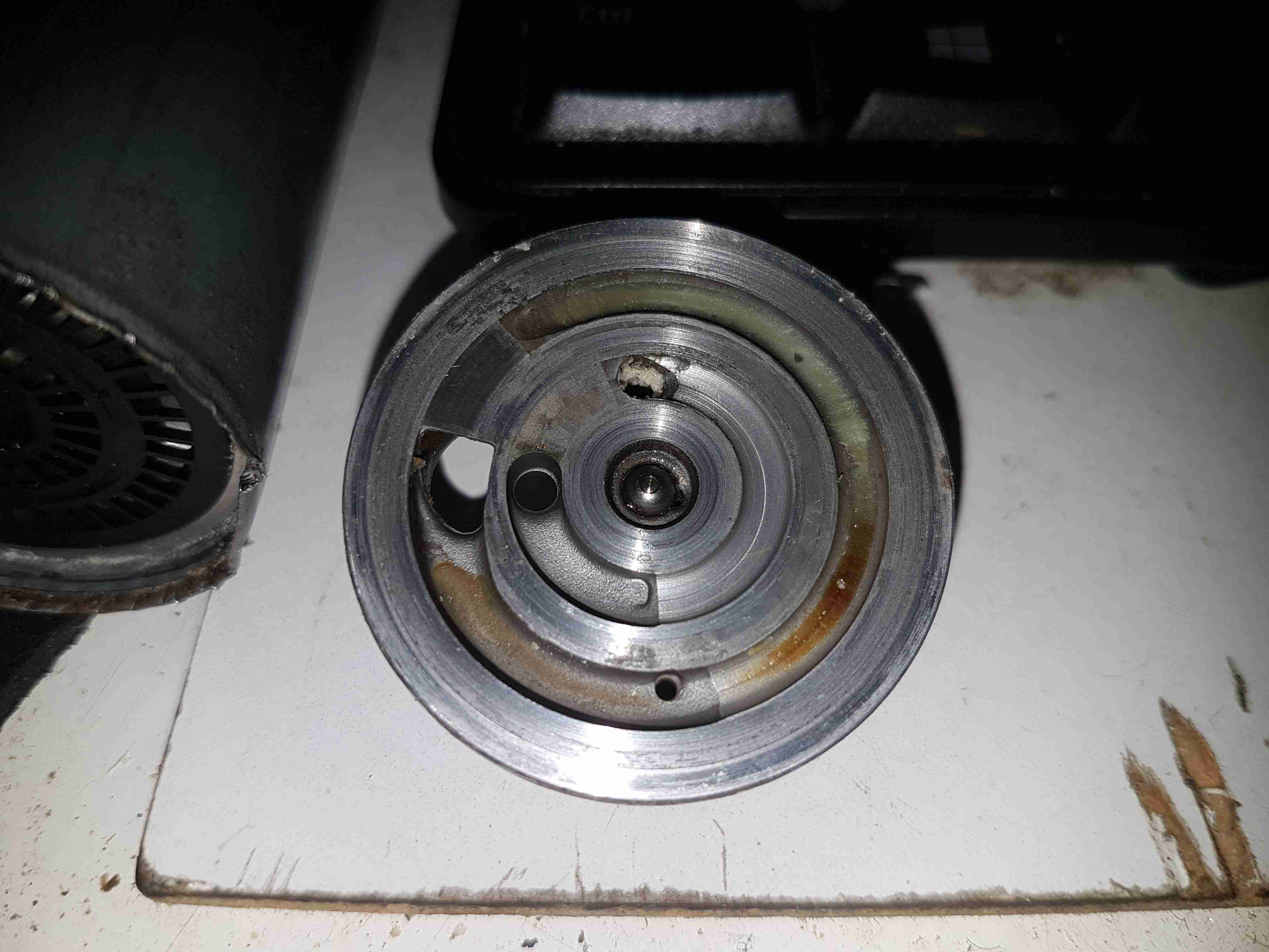
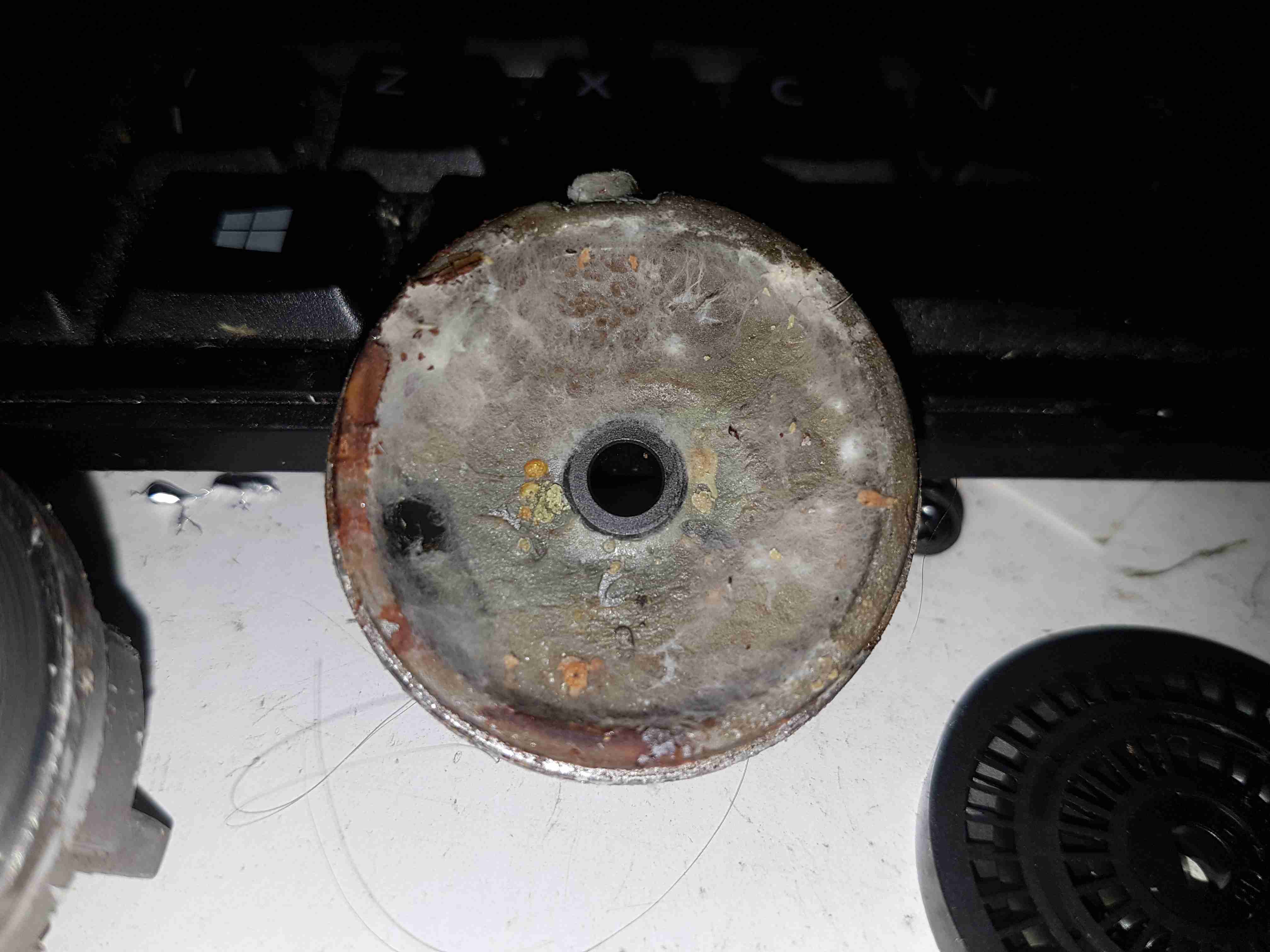
The input endbell of the pump has the fuel inlet ports, the channels are visible machined into the casting. There’s a pair of channels for two pump outputs – the main fuel rail to the engine, and an auxiliary fuel output to power a venturi pump. The fuel pump unit sits inside a swirl pot, which holds about a pint of fuel. These are used to ensure the pump doesn’t run dry & starve the engine when the tank level is low & the car is being driven hard. The venturi pump draws fuel from the main tank into the swirl pot. A steel ball is pressed in to the end bell to provide a thrust bearing for the motor armature.
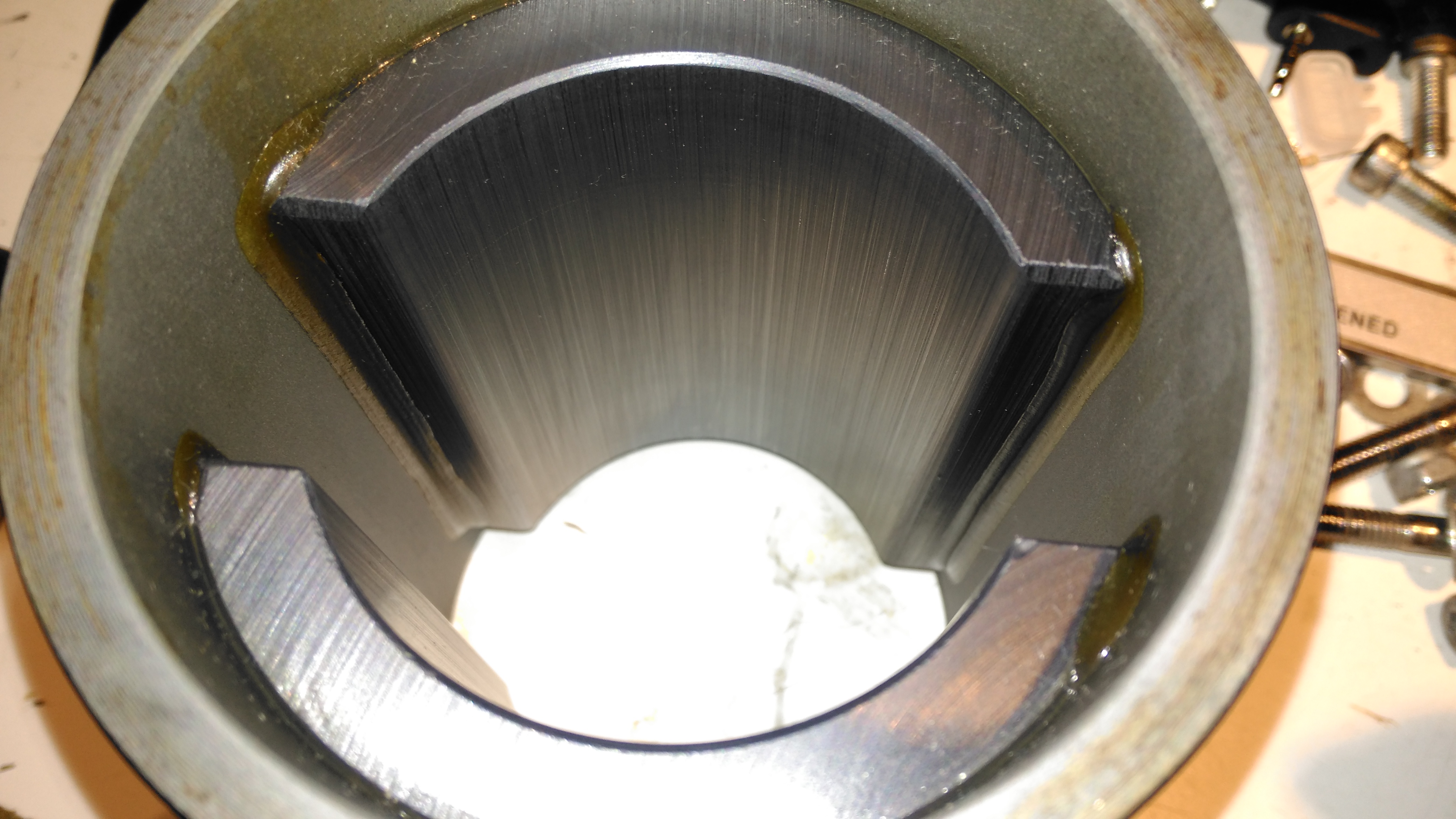
Turbine Impeller
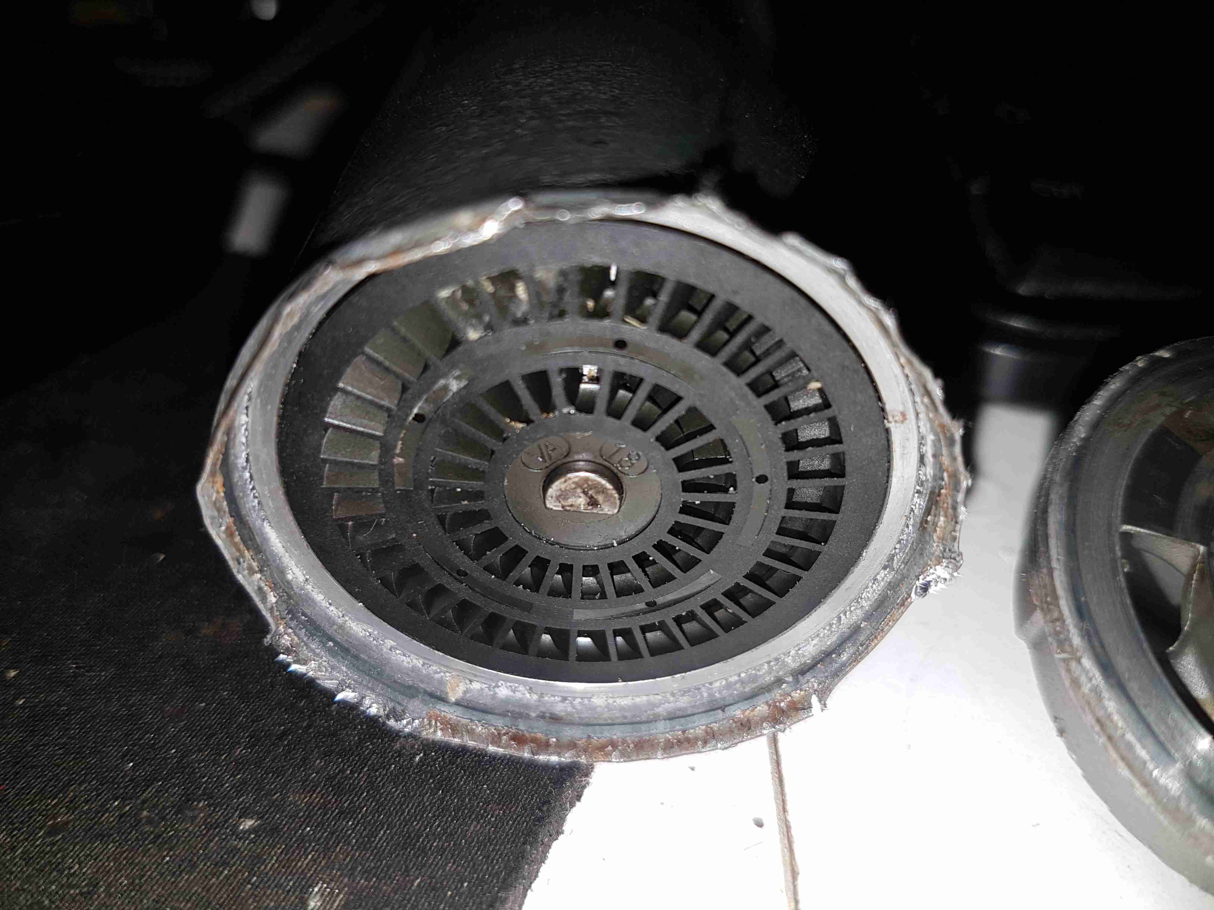
The core of the pump is this impeller, which is similar to a side-channel blower. From what I’ve been able to find these units supply pressures up to about 70PSI for the injector rail. The outside ring is the main fuel pump, while the smaller inner one provides the pressure to run the venturi pump.
Pump Housing
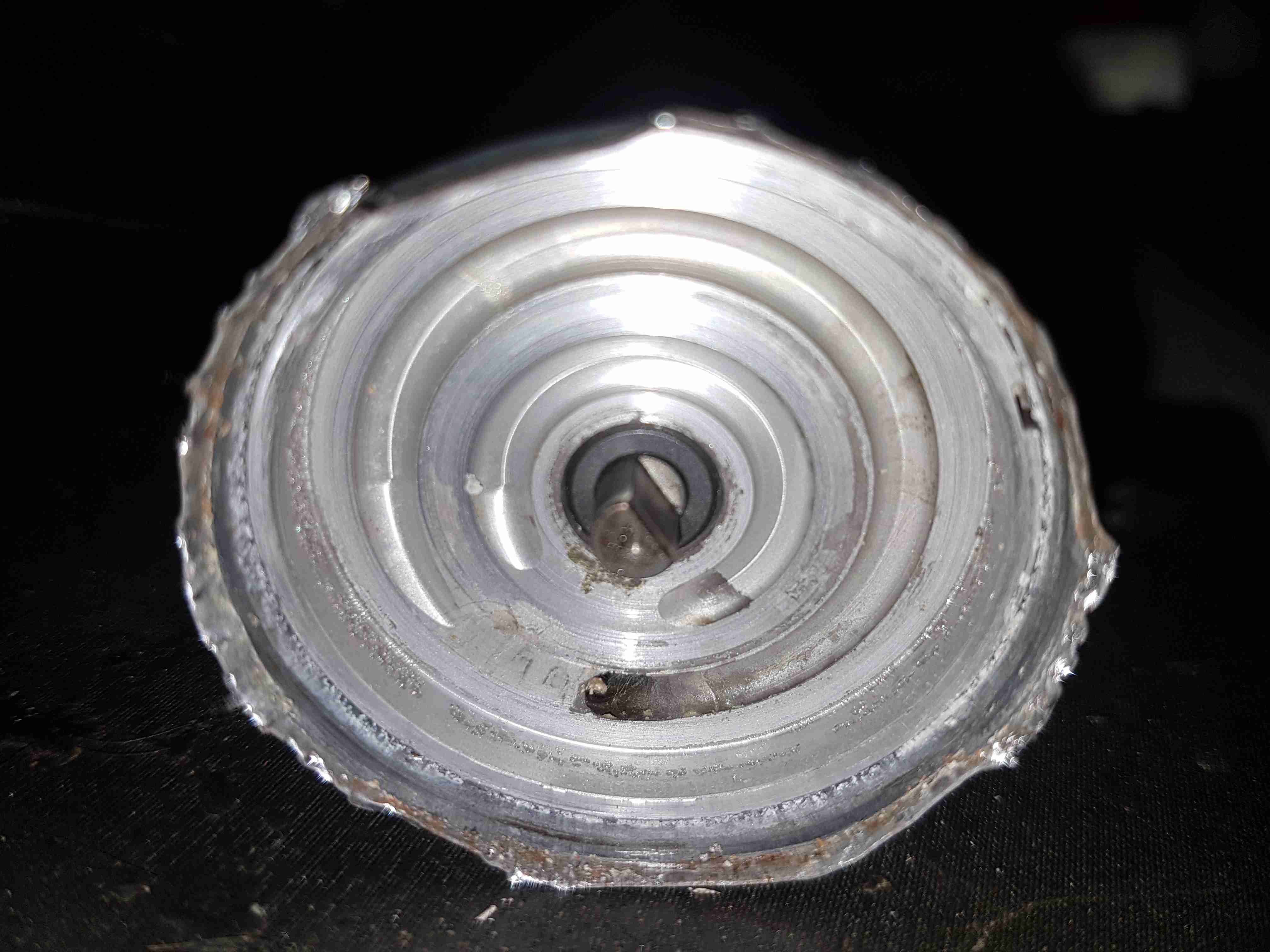
The other side of the machined pump housing has the main output channel, with the fuel outlet port at the bottom. The motor shaft is supported in what looks like a carbon bearing.
Midsection
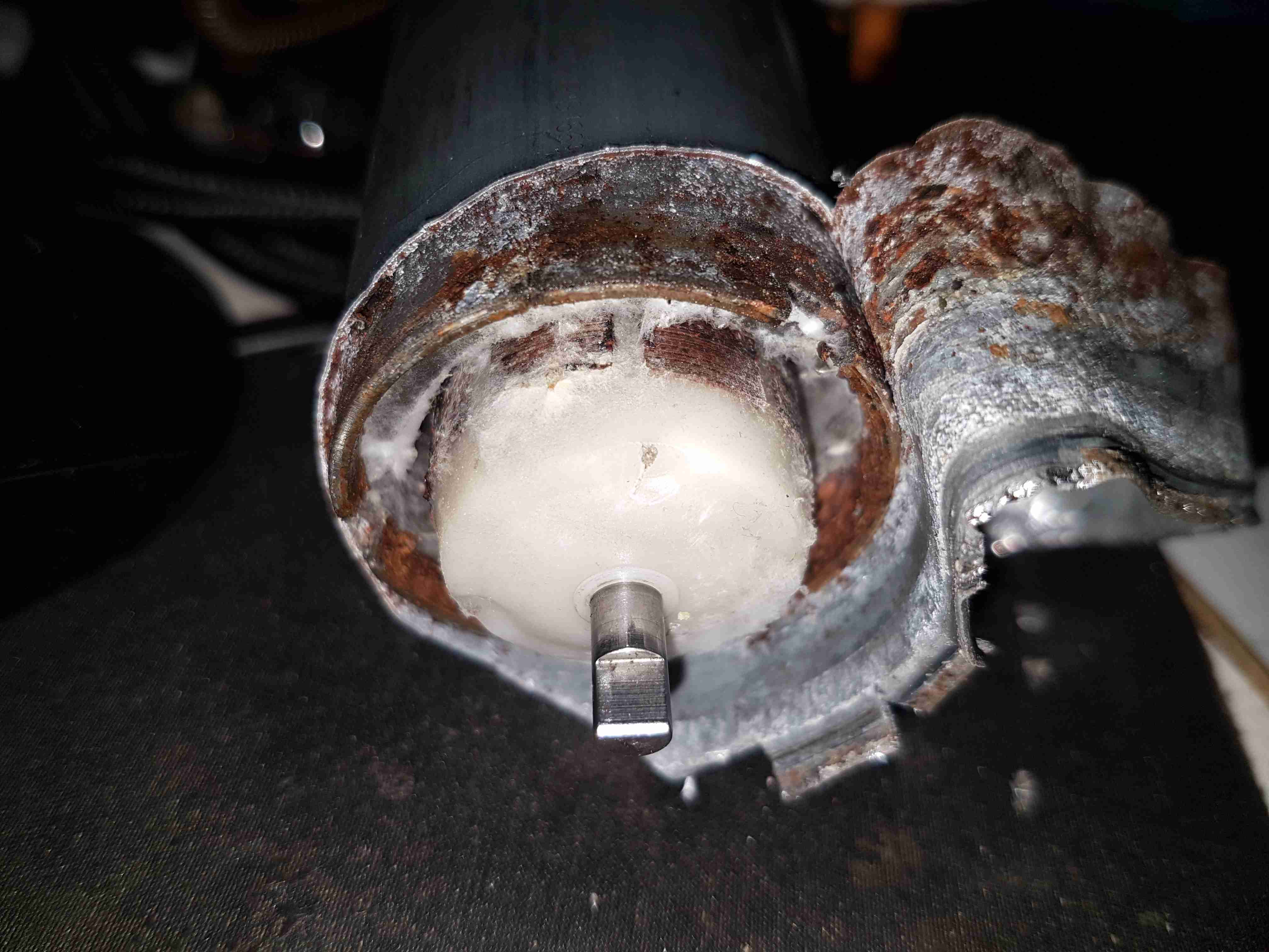
Removing the pump intermediate section with the bearing reveals quite a bit of fungus – it’s probably been happy sat in here digesting what remains of the fuel.
Armature Exposed
Some peeling with mole grips allows the motor to come apart entirely. The drive end of the armature is visible here.
Motor Can
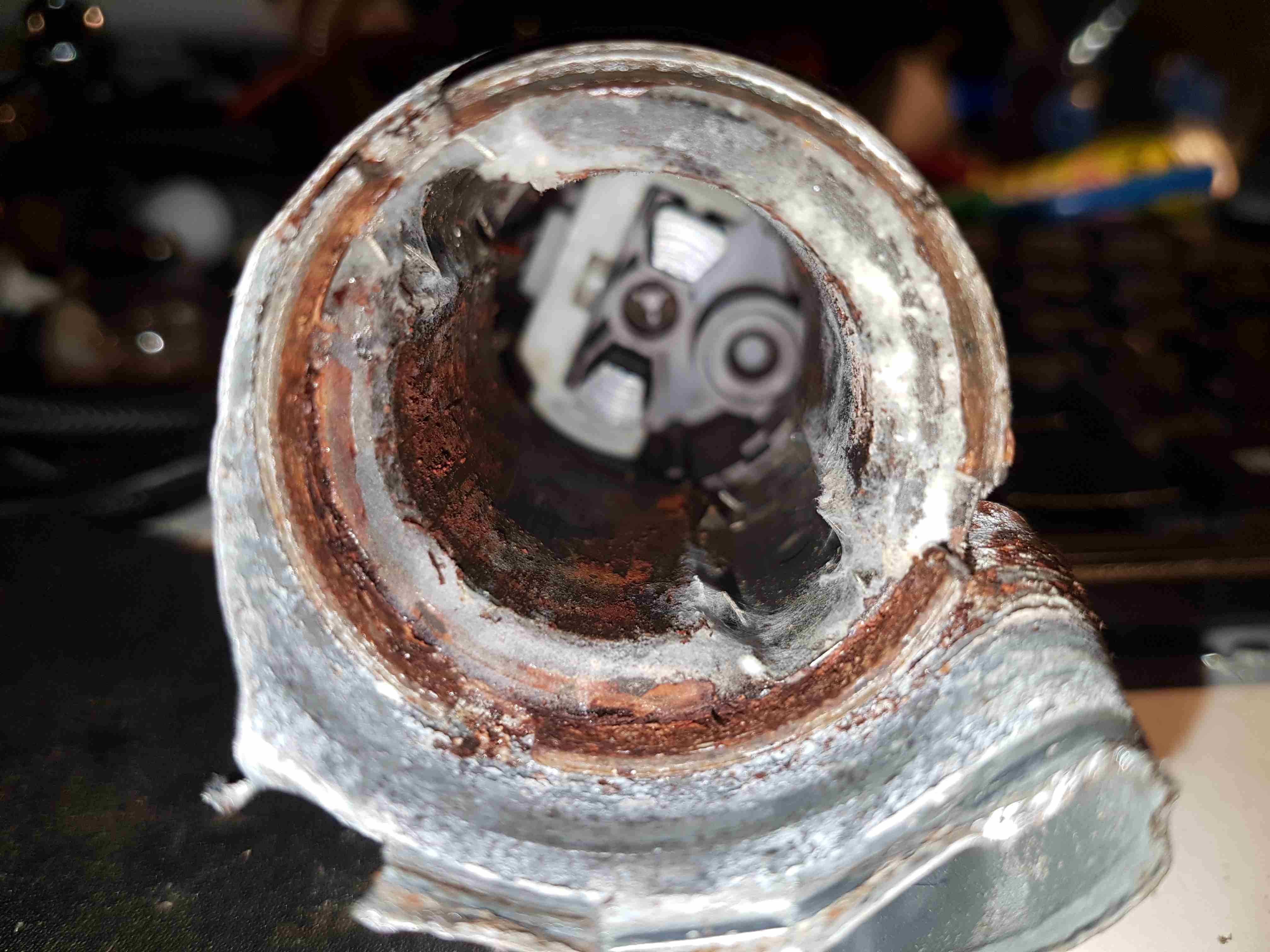
The outer shell of the motor holds yet more fungus, along with some rust & the pair of ceramic permanent magnets.
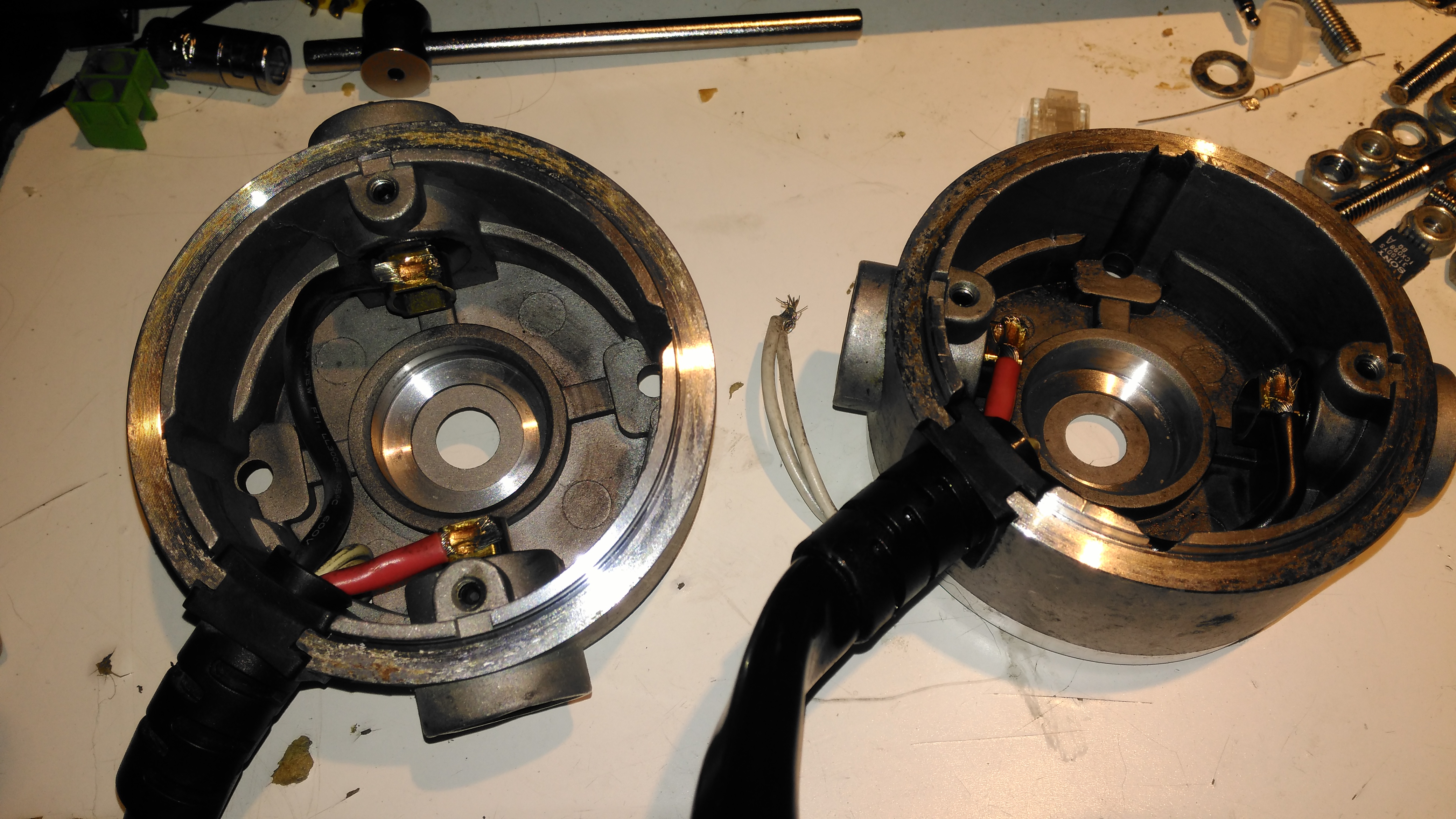
Brushes
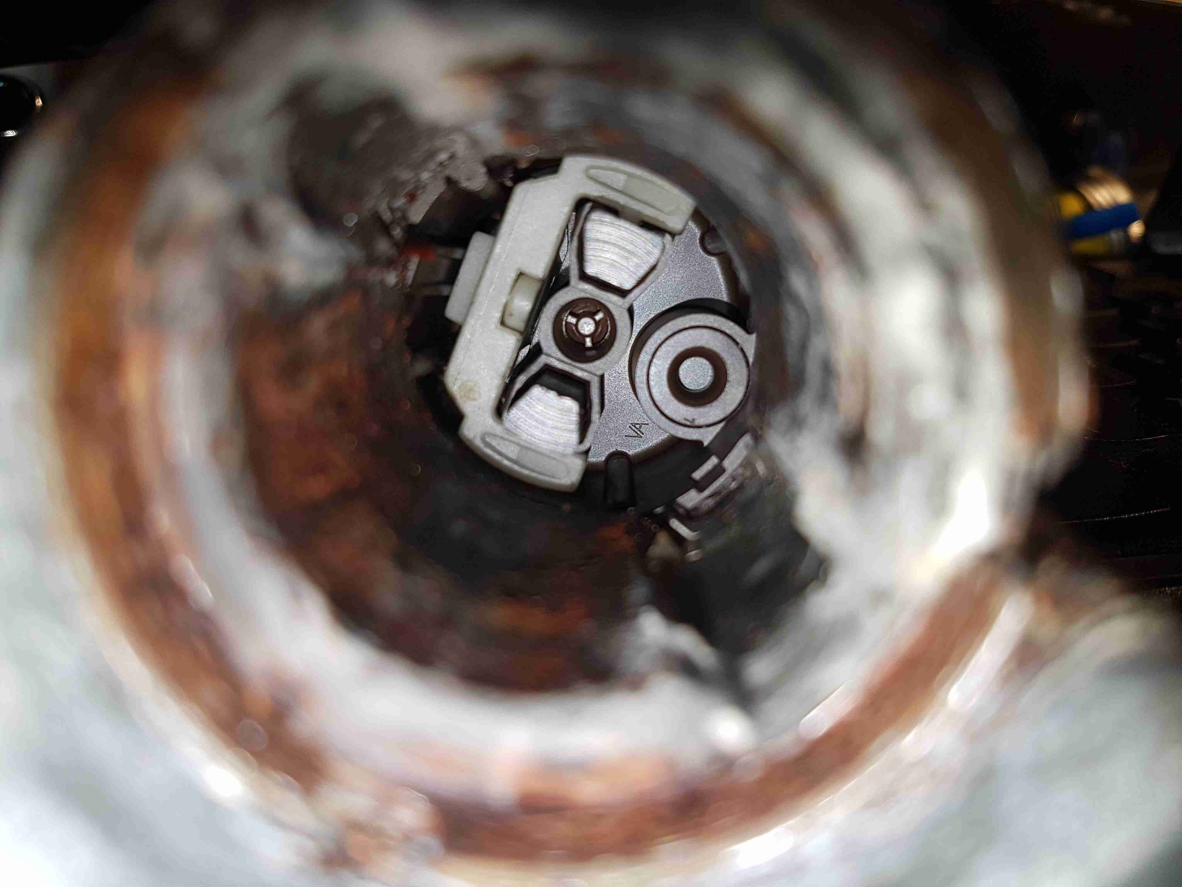
The other end of the pump has the brush assembly, and the fuel outlet check valve to the right. The bearing at this end is just the plastic end cap, since there are much lower forces at this end of the motor. The fuel itself provides the lubrication required.
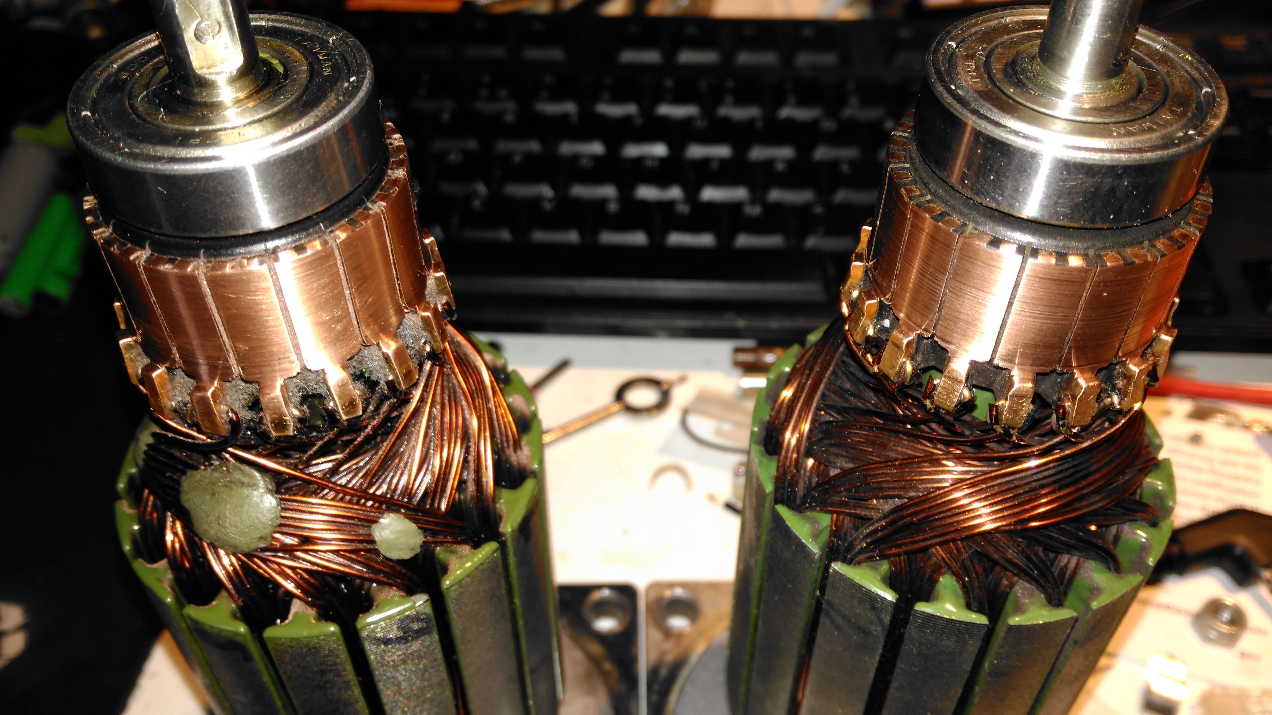
Potted Armature
With the armature pulled out of the housing, it’s clear that there’s been quite a bit of water in here as well, with the laminations rusting away. This armature is fully potted in plastic, with none of the copper windings visible.
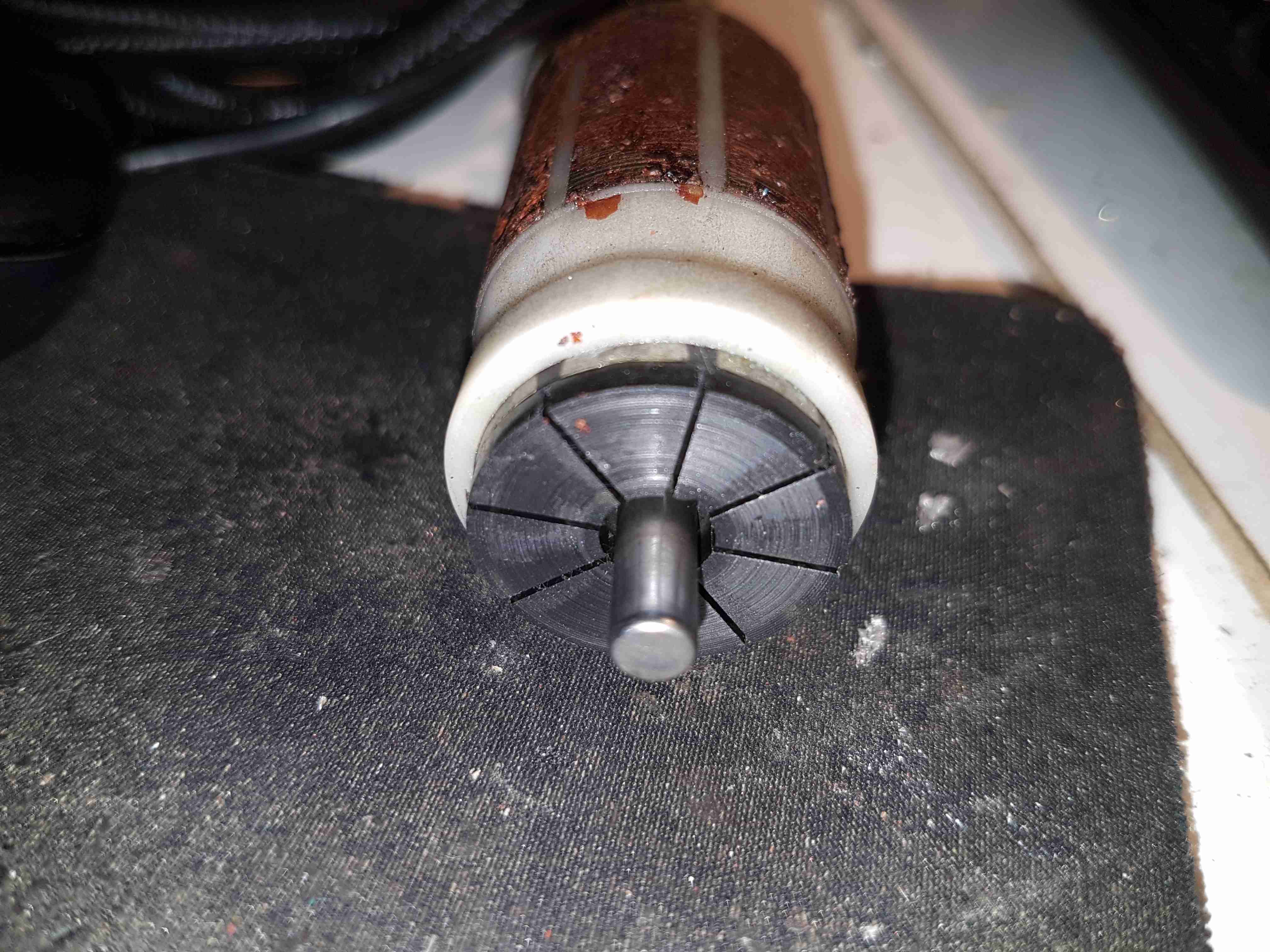
Carbon Commutator
The commutator in these motors is definitely a strange one – it’s axial rather than radial in construction, and the segments are made of carbon like the brushes. No doubt this is to stop the sparking that usually occurs with brushed motors – preventing ignition of fuel vapour in the pump when air manages to get in as well, such as in an empty tank.
The housing of the contaminated motor was left to soak in diesel for a few hours to loosen the grok, this has come very clean. I couldn’t have used a stronger solvent here – the magnets are glued in place in the steel housing, I certainly didn’t want them coming loose!
Brushboxes
Next into the diesel bath are the motor end bells with the brushgear. Attack with a stiff brush cleaned these up very well, some cotton buds served to clean out the brass brush holders.
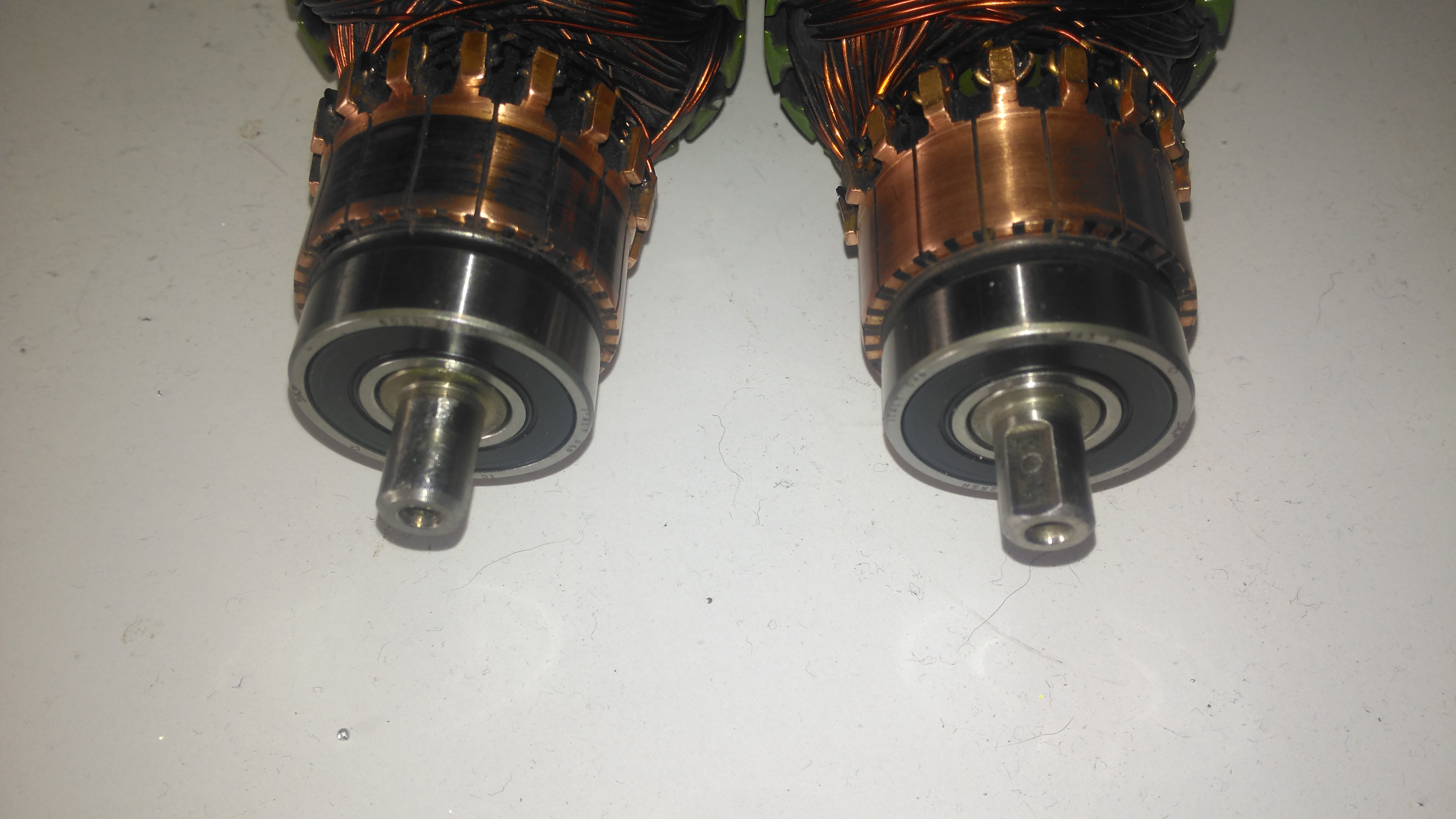
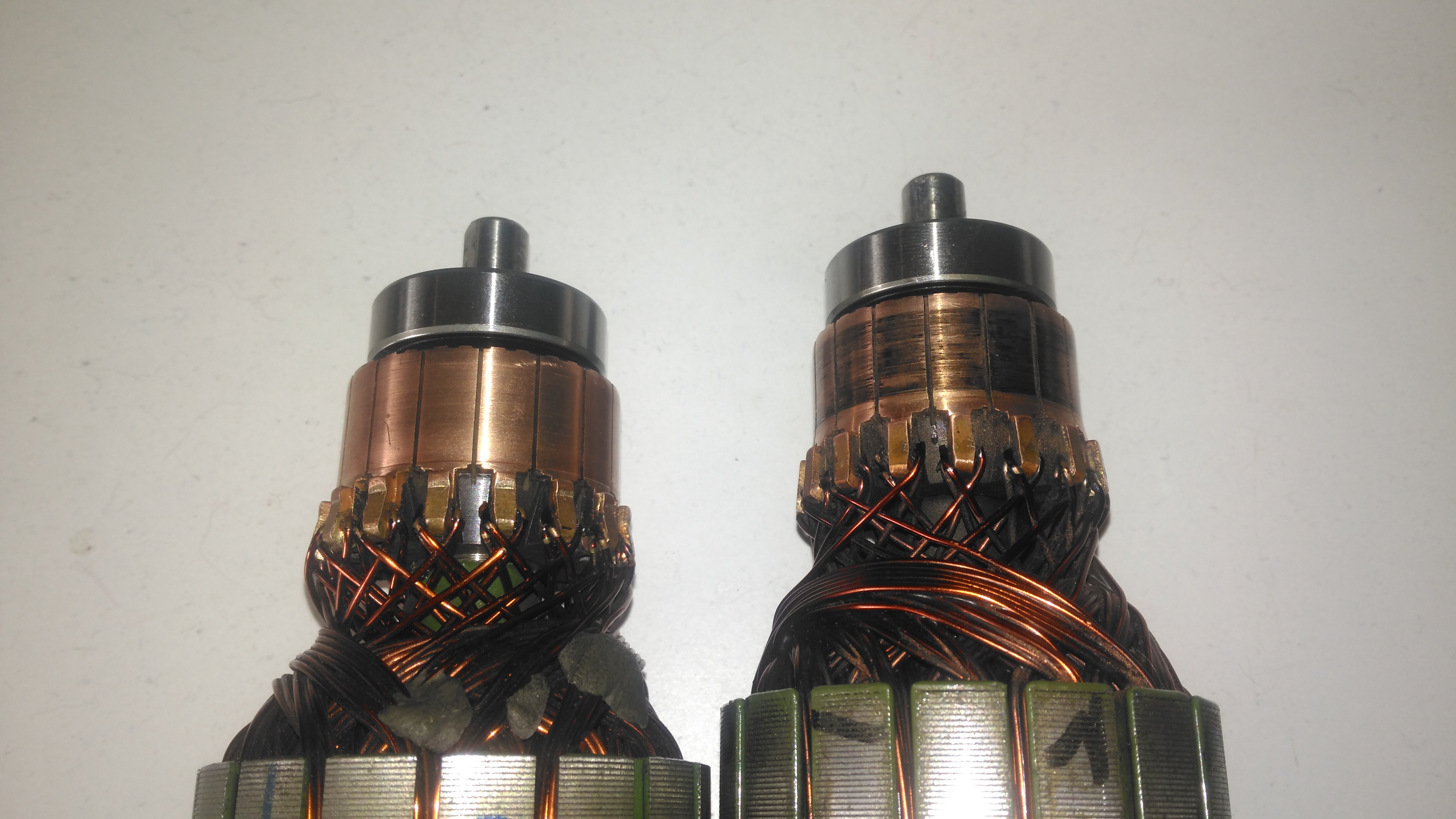
Armatures After Skimming
Here are both armatures, having had their commutators resurfaced. I’ve completely removed all traces of the wear caused by the contamination, luckly the commutator bars are very heavy on these motors so can take quite a bit of wear before there’s not enough left to skim. I’ve not yet pulled off the old bearings, but they are all going to be replaced with new SKF bearings, as they’ve been contaminated with grok over the years of use. I’m also going to uprate the front motor bearings to rubber sealed instead of metal shielded, to help keep lubricant out of the motors if the gearbox seals ever fail again.
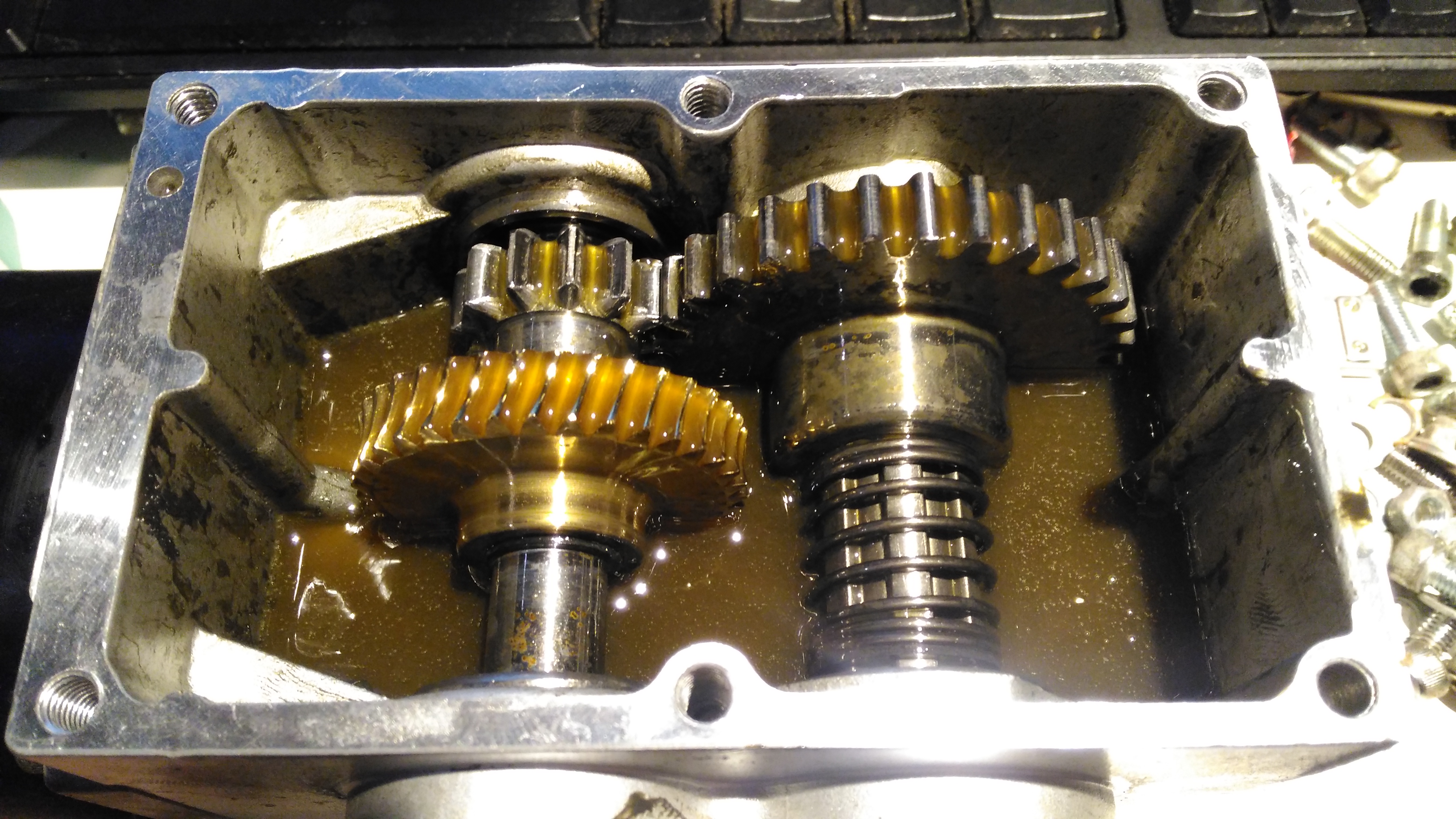
Gearbox
The gearboxes have been cleaned out with some elbow grease, assisted by a long soak in petrol, I’ve refilled them here with engine oil as temporary lube & to flush out the last remains of the old grease & solvent. The worm wheel in these boxes is bronze – so a GL4 gear oil will be required. (Some Extreme Pressure additive packs contain sulphur, and will readily attack copper alloys, such as brass & bronze).
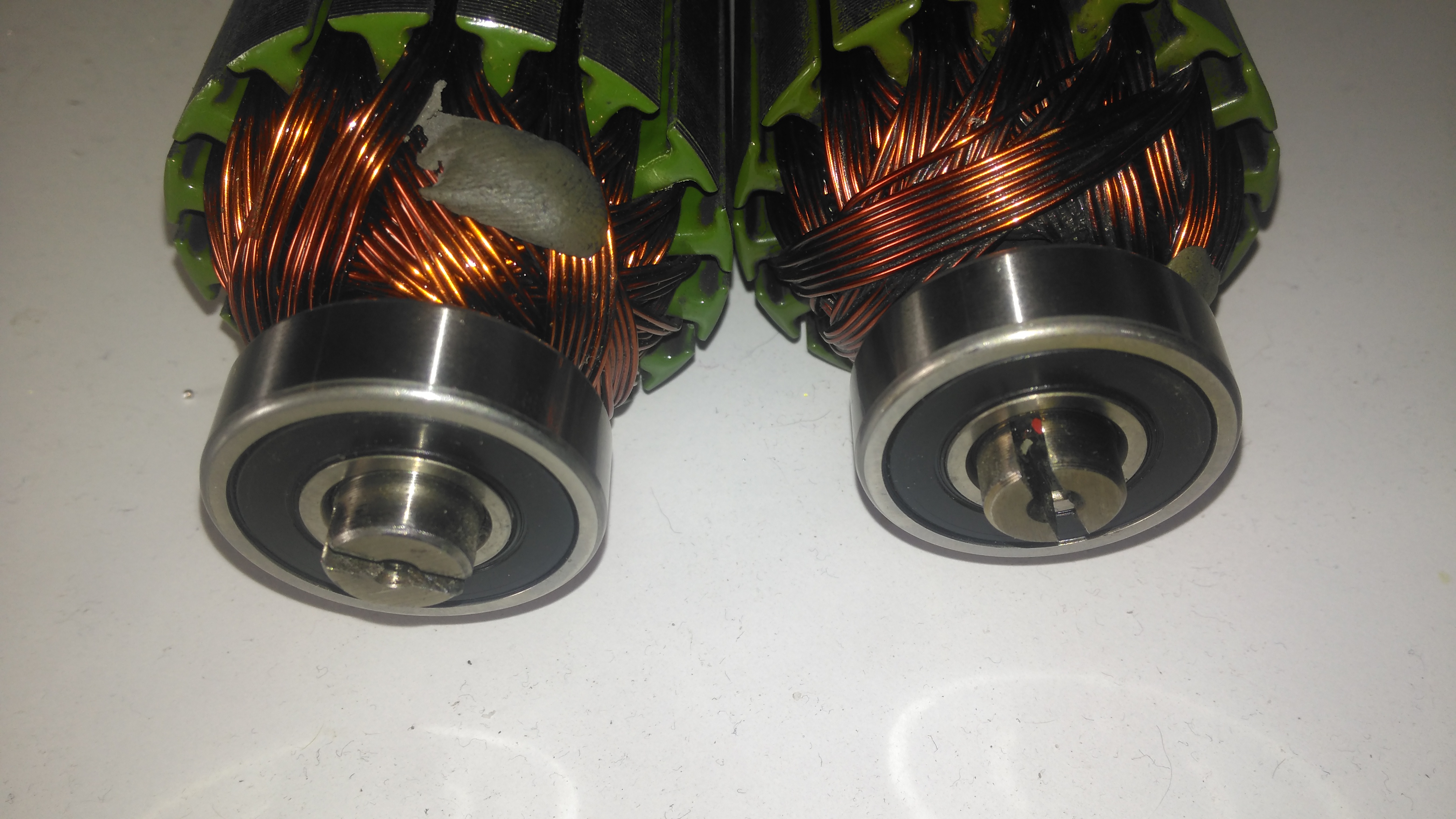
Commutator End Bearings
Here’s the armatures, after the new SKF sealed bearings have been fitted to the commutator end, above, and the drive end, below. These will cause some extra drag on the armatures, and slightly higher power consumption as a result, but keeping the crap out of the motors is slightly more important.
Drive End BearingsFresh Commutator Skim
The commutators have been lightly skimmed with abrasive cloth, and finished with 1500 grit emery. The armature on the right has been run for a short time to see how the new brushes are bedding in.
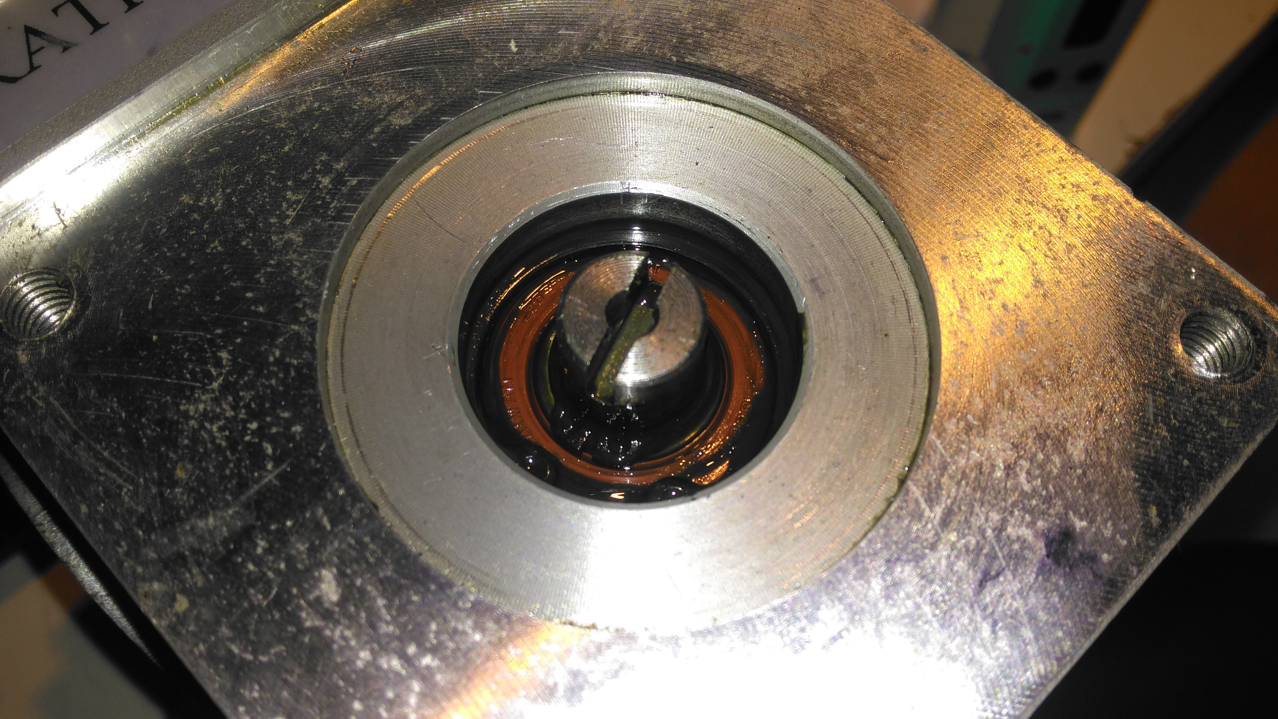
Old Seal Removed
Finally, the old oil seals are pulled from the gearboxes. The worm gear bearing on the inside is actually a sealed version, with the external oil seal providing some extra sealing. I haven’t changed the gearbox bearings, as they seem to be in good order, this might get done at some point in the future.
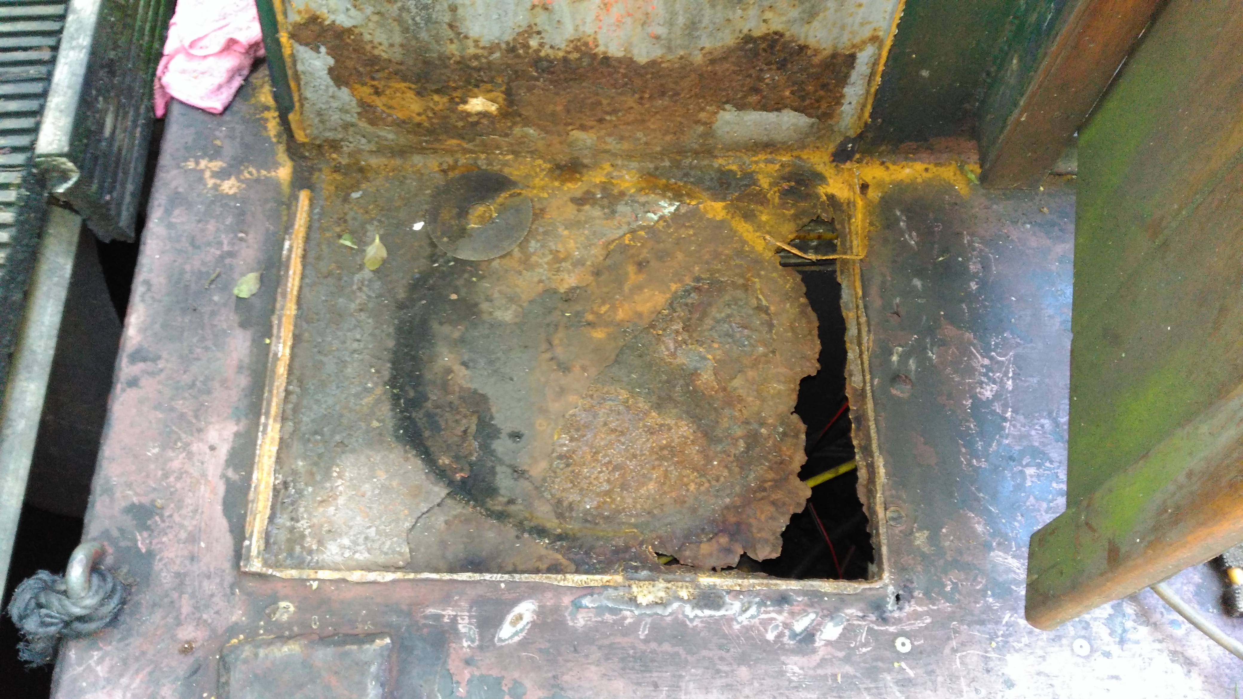
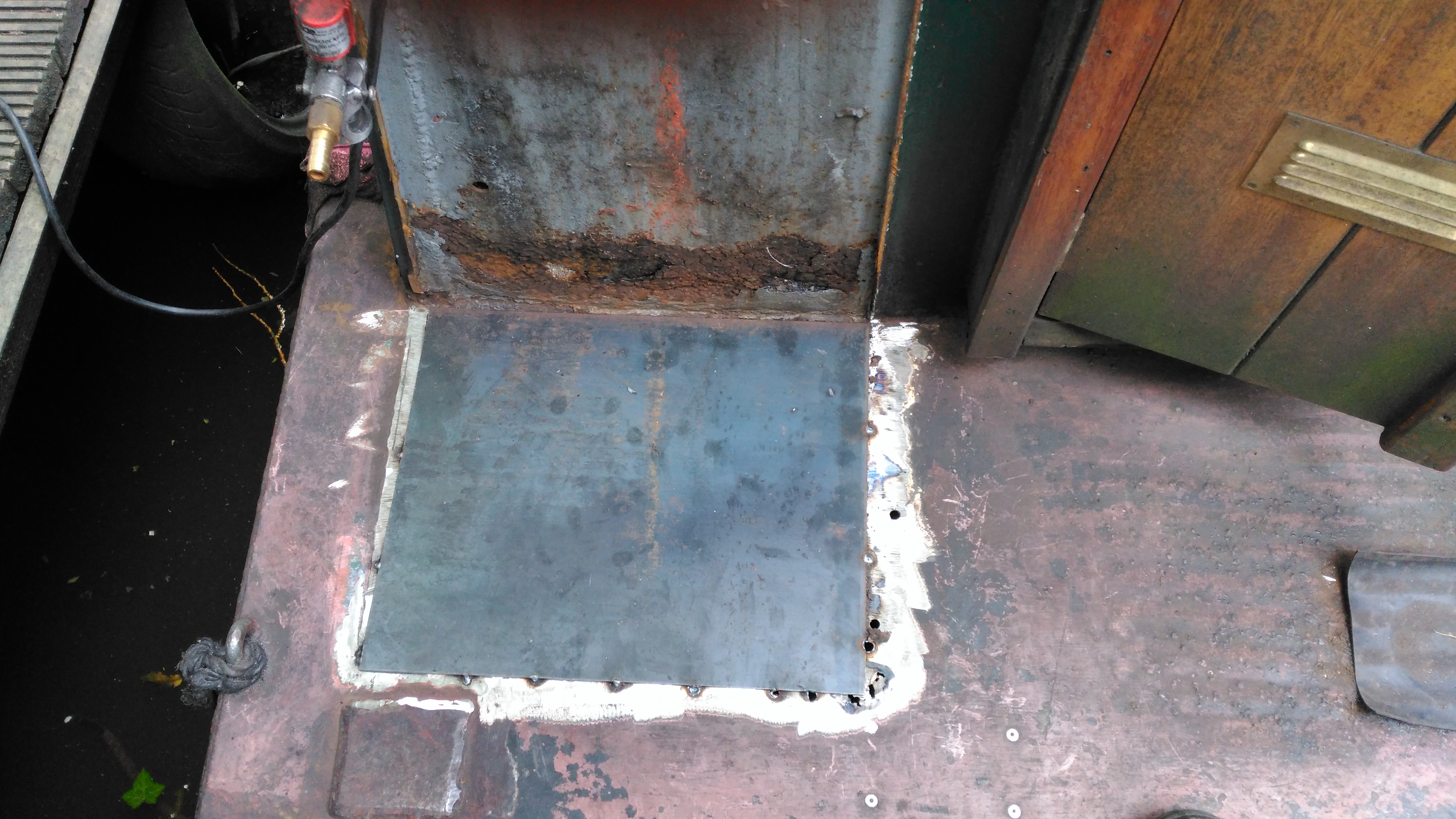
This is a part of the boat that hasn’t really had much TLC since we moved aboard, and finally it’s completely succumbed to corrosion, opening a rusty hole into the engine space below. I’ve already used a grinder to remove the rest of the locker – and even this had corroded to the point of failure all around the bottom just above the welds. The bulkhead forming the rear of the locker has also corroded fairly severely, so this will be getting cut out & replaced with a new piece of steel.
This was originally a 1/8″ plate, but now it’s as thin as foil in some places, with just the paint hiding the holes.
Replacement Steel
I’ve cut out as much of the corroded deck plate as possible – it’s supported underneath by many struts made of angle iron, and got the new 3mm replacement tacked in place with the MIG. I’ve not yet cut out the rotten section on the bulkhead, this will come after we’ve got the steel cut to replace it, as electrical distribution is behind this plate – I’d rather not have weather exposure to the electrical systems for long! Unfortunately more corrosion has showed itself around the edges of the old locker:
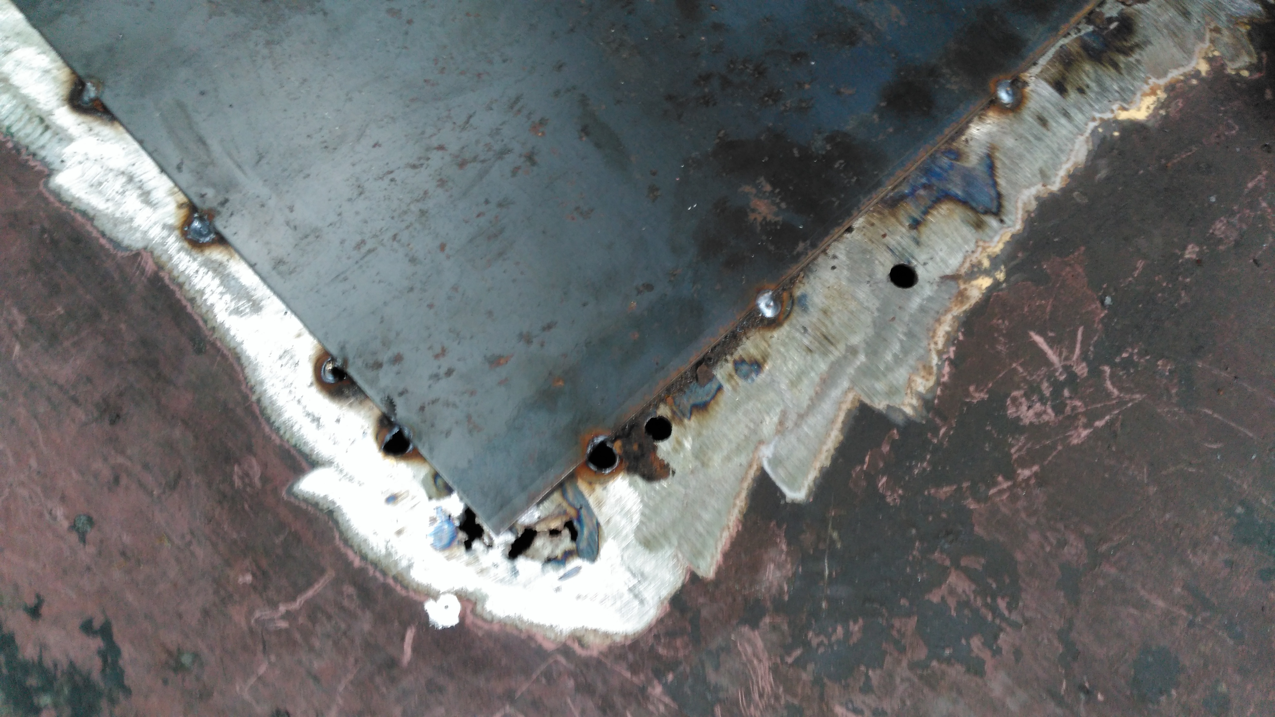
Thin Steel
Around the corner the steel has pretty much totally failed from corrosion coming from underneath – applying welding heat here has simply blown large holes in the steel as there’s nothing more than foil thickness to support anything.
Some more extensive deck replacement is going to happen to fix this issue, more to come when the steel comes in!
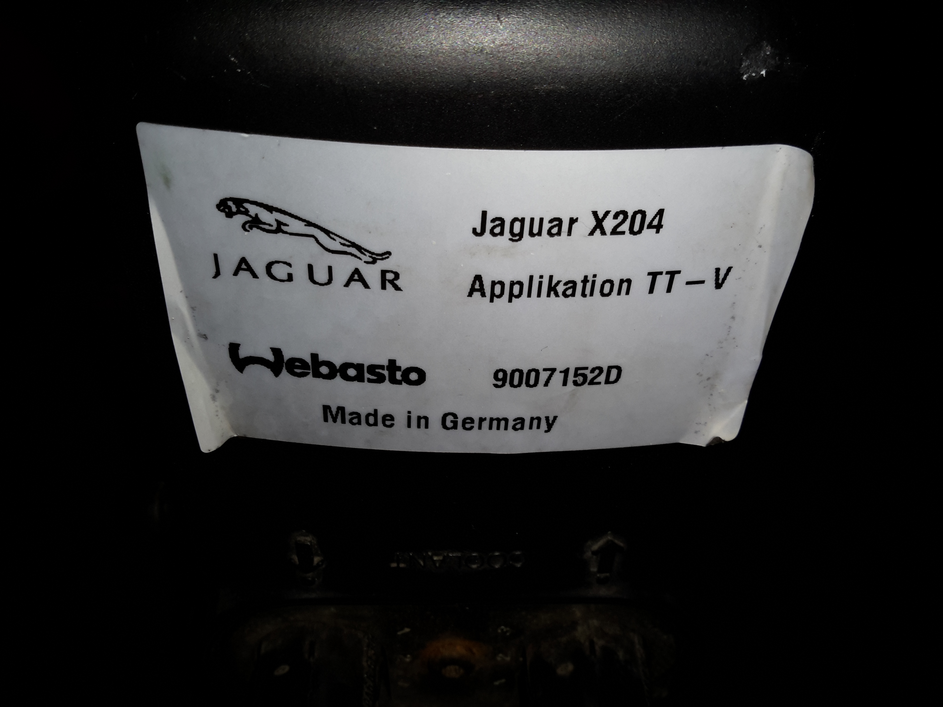
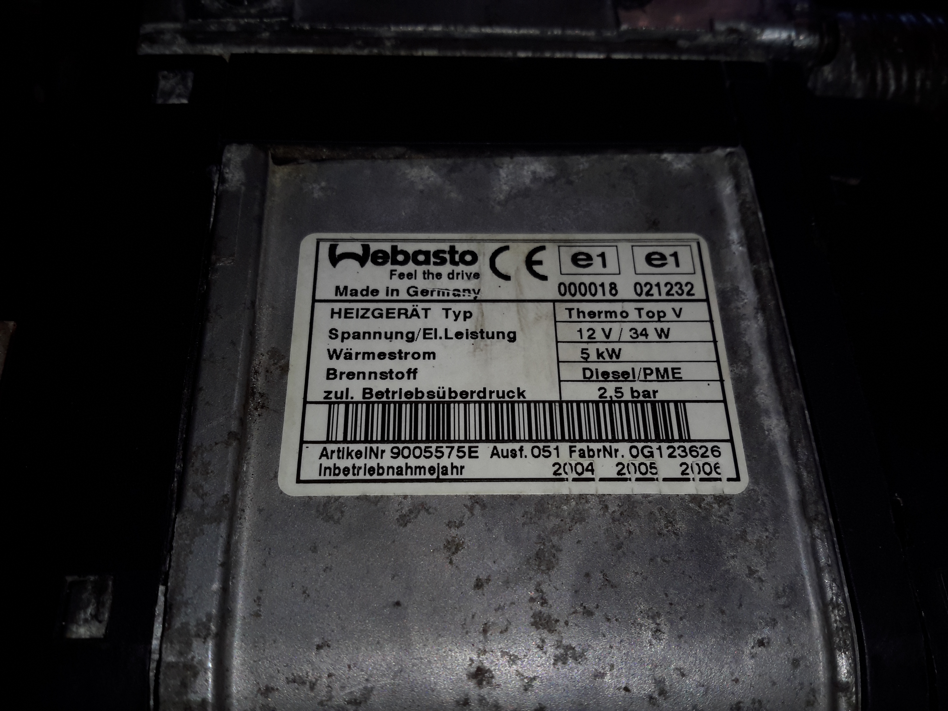
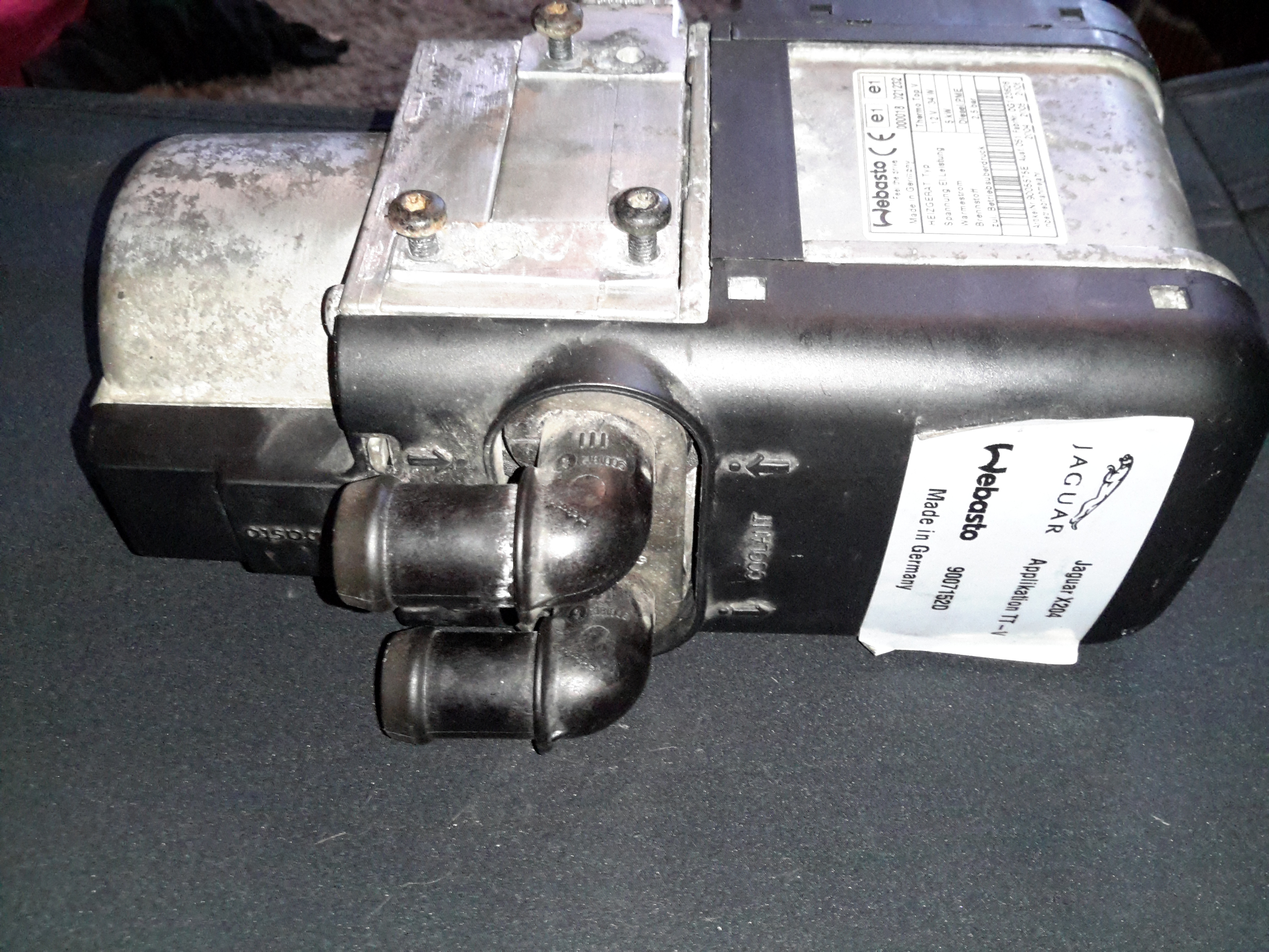
Here’s another Diesel-fired heater related project – these Webasto heaters are fitted to Jaguar S-Type cars as auxiliary heaters, since (according to the Jag manual), the modern fuel-efficient diesels produce so little waste heat that extra help is required to run the car’s climate control system. (Although this seems to nullify any fuel efficiency boost, as the fuel saved by not producing so much waste heat in the engine itself is burned in an aux heater to provide heat anyway). The unfortunate part is these units don’t respond to applying +12v to Pin 1 of the ECU to get them to start – they are programmed to respond to CAN Bus & K-Line Bus only, so they require a bit more effort to get going. They also don’t have a built-in water circulation pump unlike the Webasto Thermo Top C heaters – they expect the water flow to be taken care of by the engine’s coolant pump.
Webasto LabelWater Side
The water ports are on the side of this heater instead of the end, the heat exhanger is on the left. These hearers are fitted to the car under the left front wing, behind a splash guard. Pretty easy to get to but they get exposed to all the road dirt, water & salt so corrosion is a little problem. The fuel dosing pump is in a much more difficult spot to get at – it’s under the car next to the fuel tank on the right hand side. Access to the underside with stands is required to get at this.
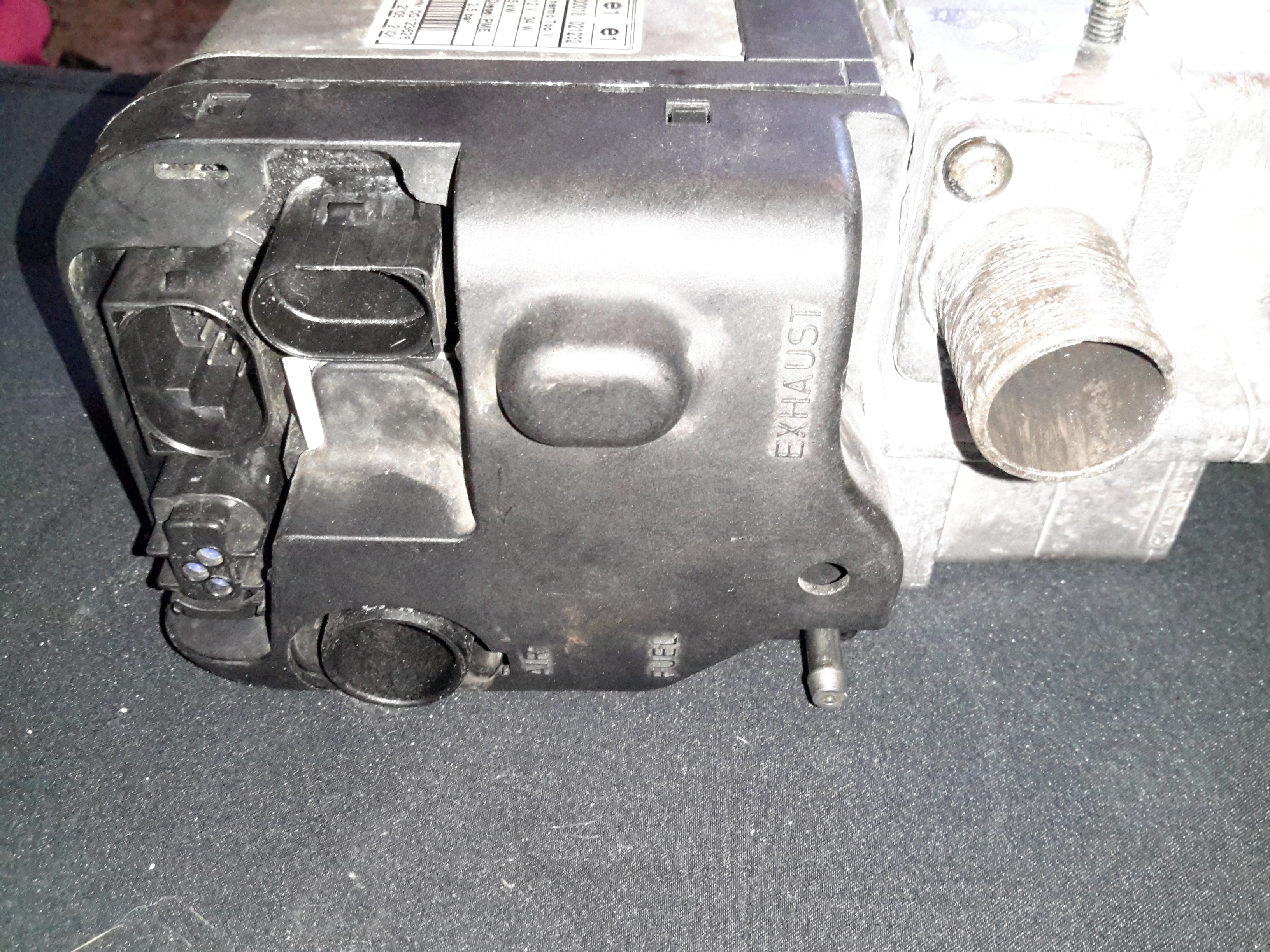
ECU Side
The ECU side has all the other connections – Combustion air, exhaust, fuel, power & control.
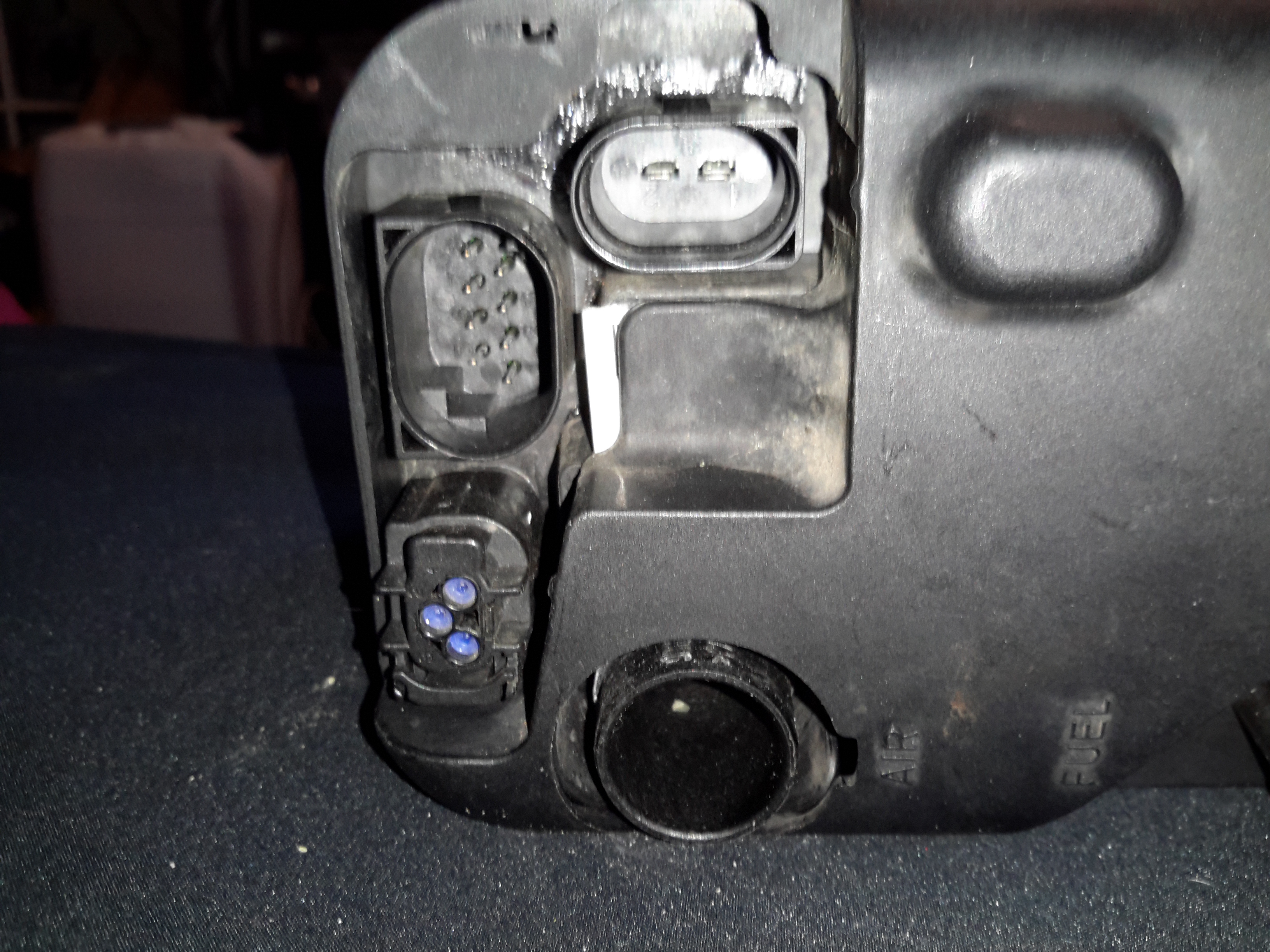
External Connectors
Only two of the external connectors are used on these heaters, the large two pin one is for main power – heavy cable required here as the current draw can climb to ~30A on startup while the glow plug fires. The 8-pin connector on the left is the control connector, where the CAN / K-Line / W-Bus buses live. The fuel dosing pump is also supplied from a pin on this connector. The small 3-pin under that is a blank for a circulation pump where fitted. Pinouts are here:
Pin
Signal
1
Battery Positive
2
Battery Negative
Pin Number
Signal
Notes
1
Telestart / Heater Enable
Would usually start the heater with a simple +12v ON signal, but is disabled in these heaters.
2
W-Bus / K-Line
Diagnostic Serial Bus Or Webasto Type 1533 Programmer / Clock
3
External Temp Sensor
4
CAN-
CAN Bus Low
5
Fuel Dosing Pump
Fuel Pump output. Connect pump to this pin & ground. Polarity unimportant.
6
Solenoid Valve
Fuel cutoff solenoid optionally fitted here.
7
CAN+
CAN Bus High
8
Cabin Heater Fan Control
This output switches on when heater reaches +50°C to control car heater blower
Pin
Signal
Notes
1
?
?
2
Circulation Pump +
3
Circulation Pump -
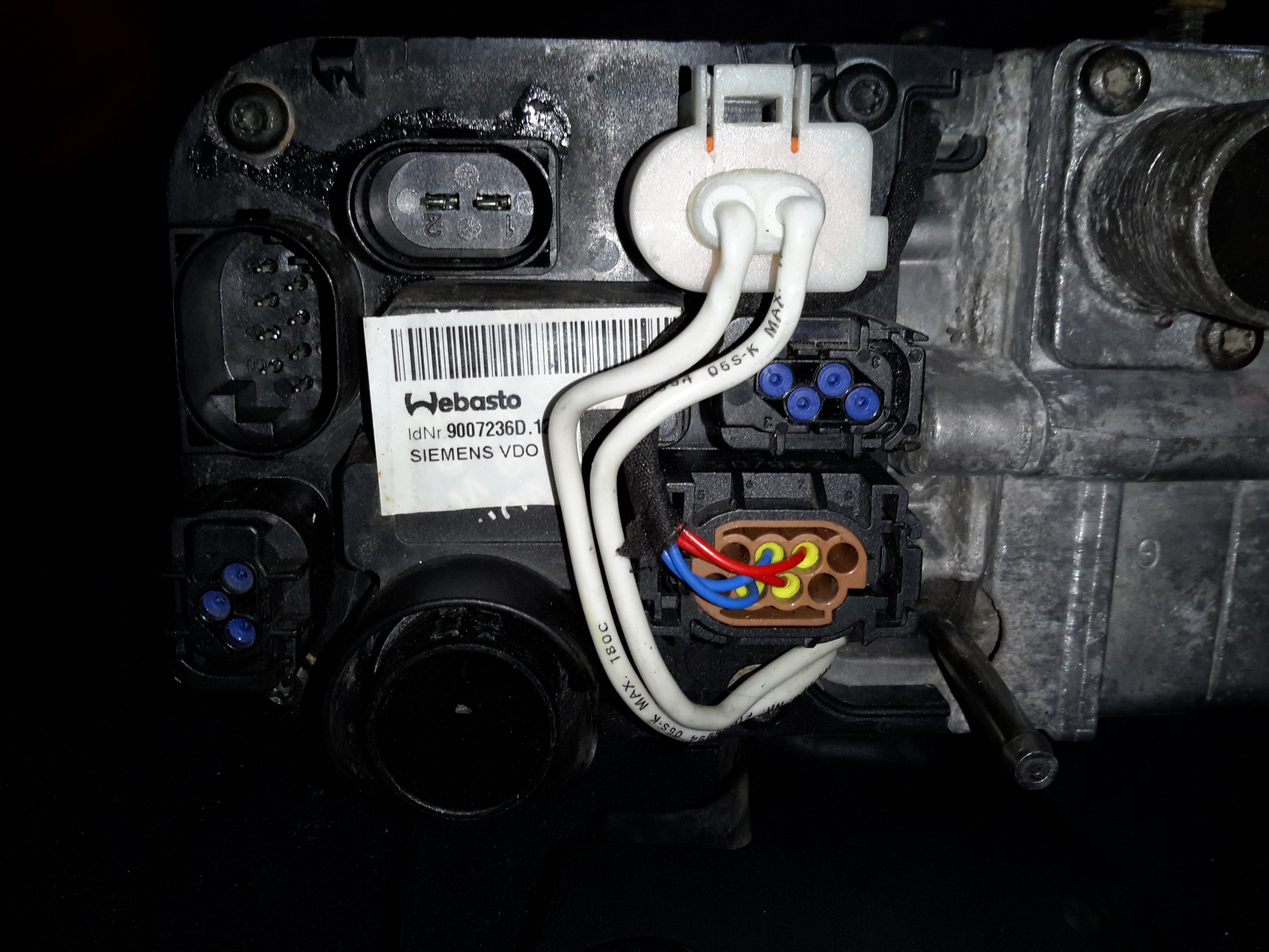
ECU Cover Removed
Removing the clipped-on plastic cover reveals the other ECU connectors. The large white one feeds the glow plug, & the large multi-pin below brings in the temp & overheat sensor signals.
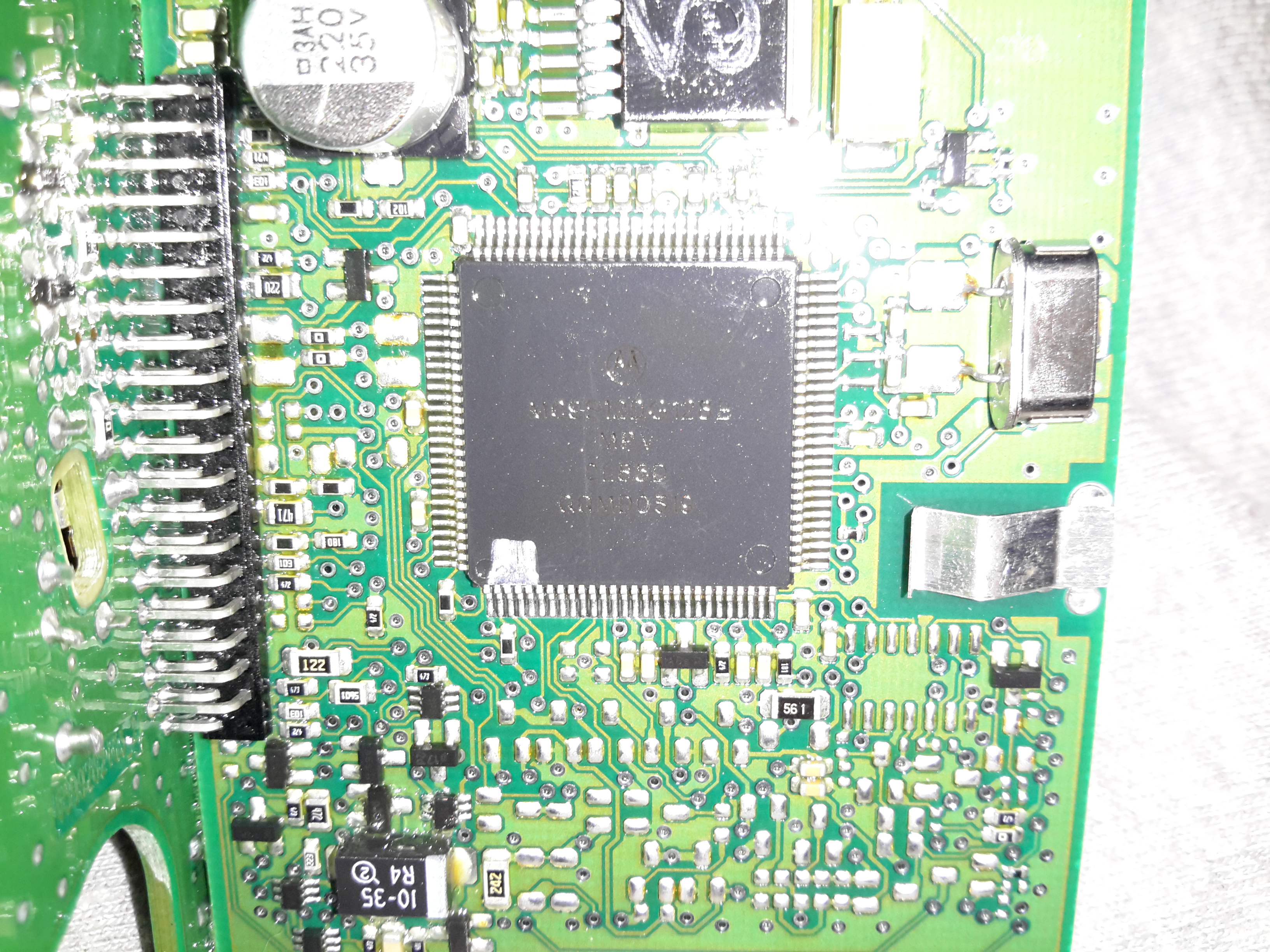
MC9S12DT128B Microcontroller
The heart of the ECU is a massive microcontroller, a Freescale MC9S12DT128B, attached to a daughterboard hooked into the ECU power board.
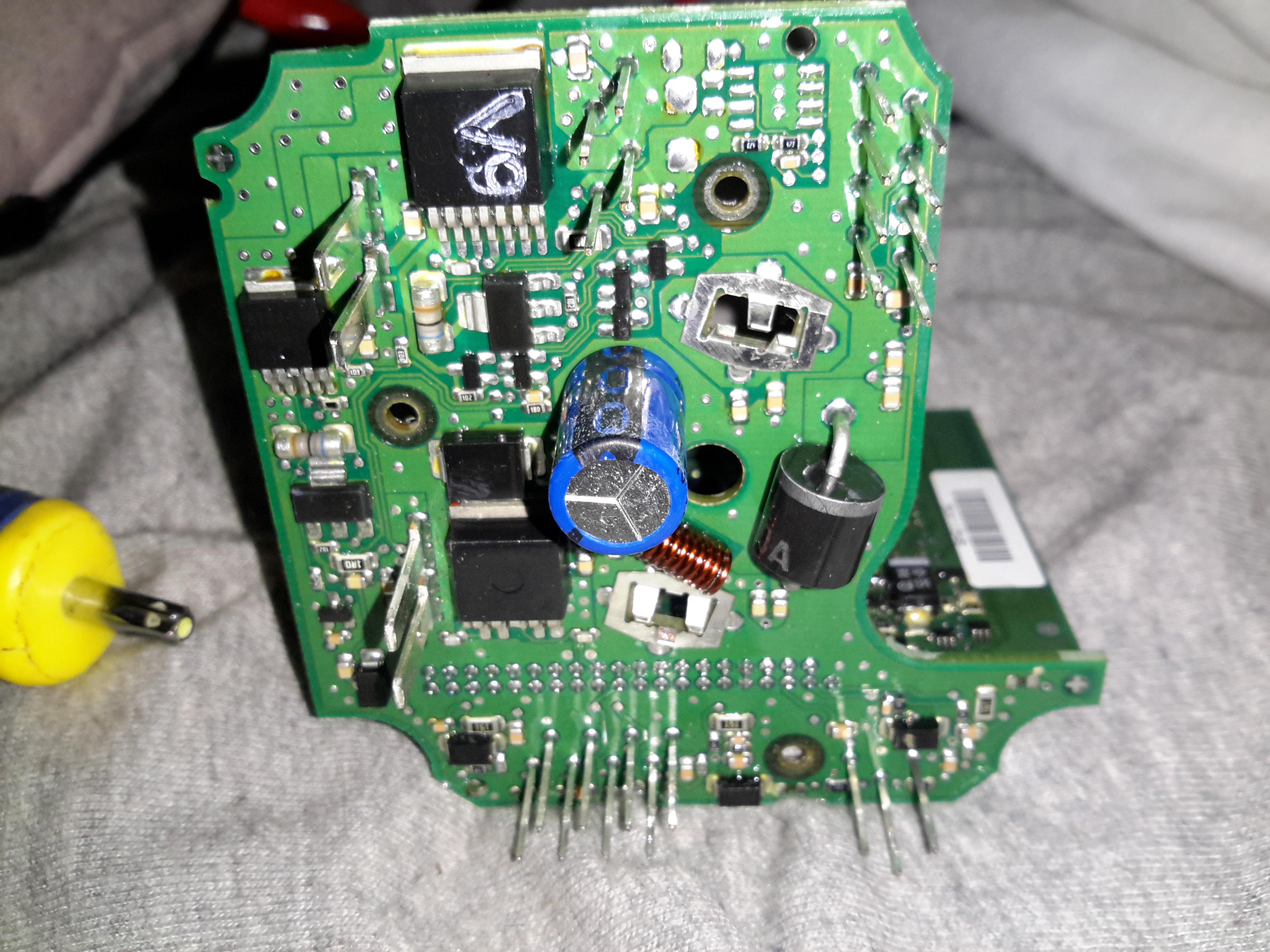
Power Section
The high power section is on the board just under the connectors, here all the large semiconductors live for switching the fan motor, glow plug, external loads, etc.
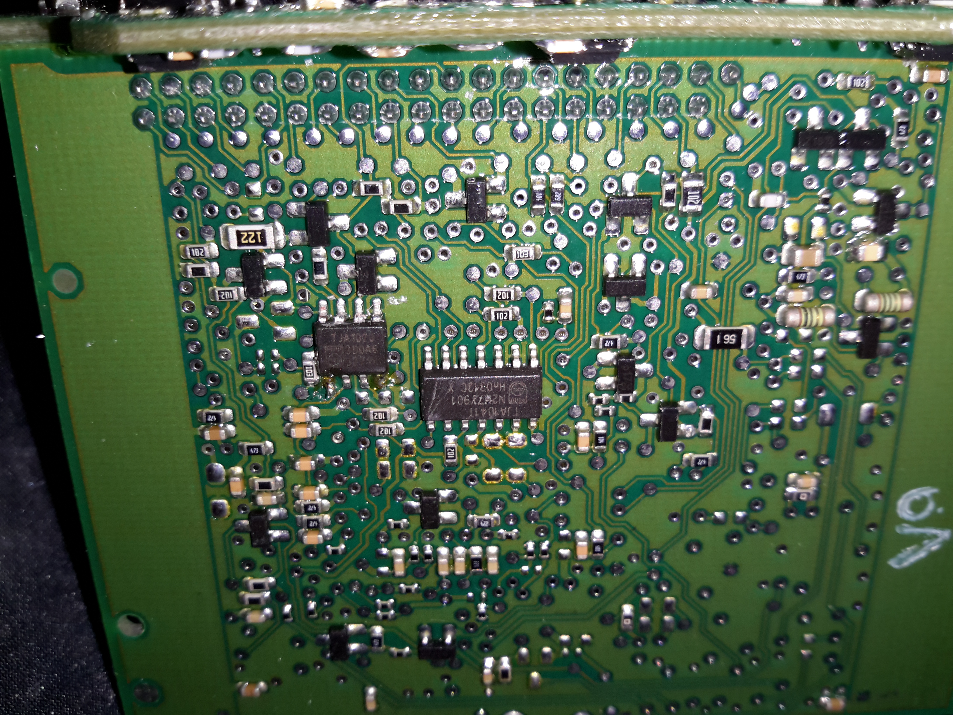
LIN & CAN Bus Transceivers
The bus transceivers are separate ICs on the control board, a TJA1041 takes care of the CAN bus. There’s also a TJA1020 LIN bus transceiver here, which is confusing since none of the Webasto documentation mentions LIN bus control.
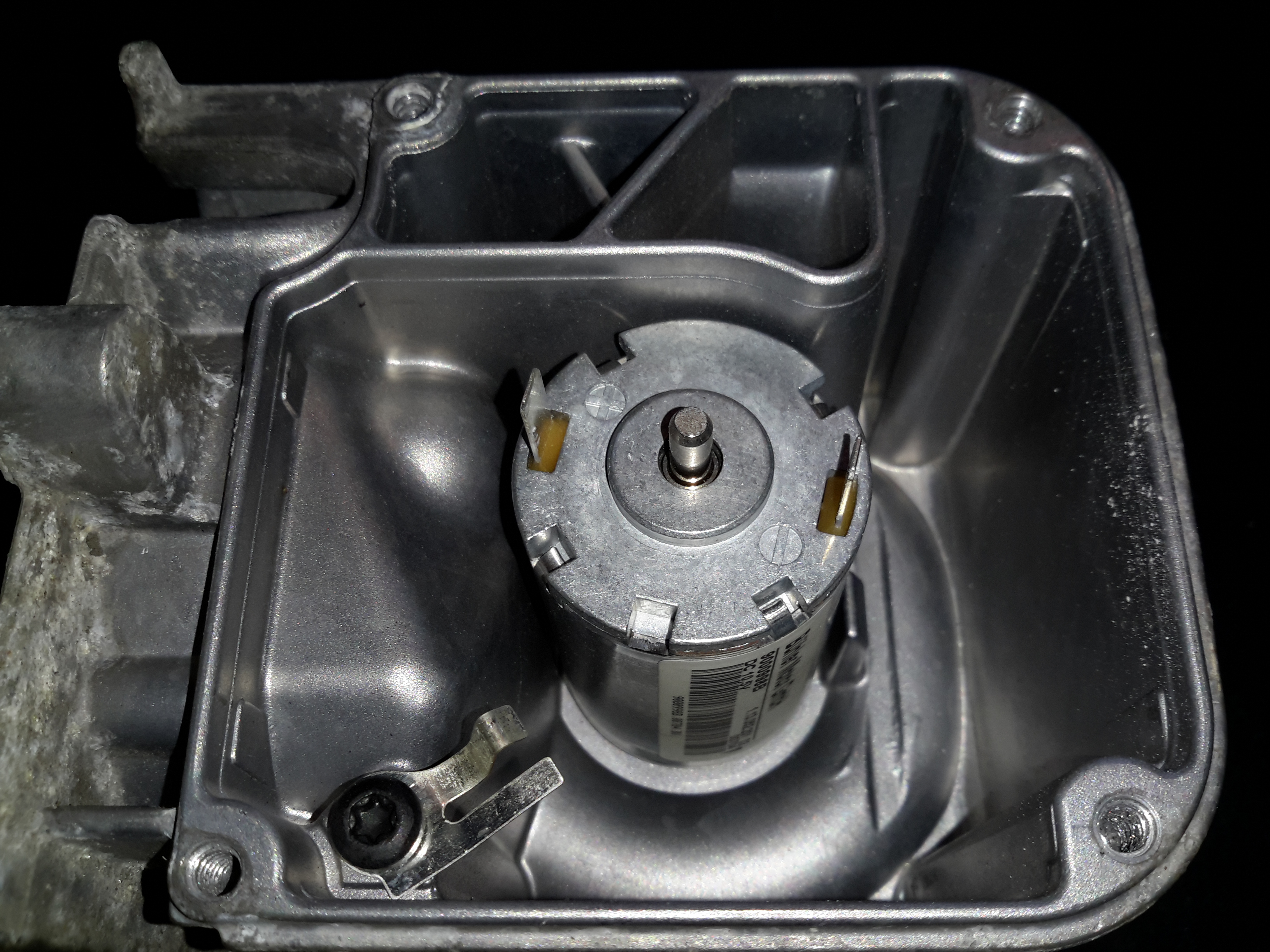
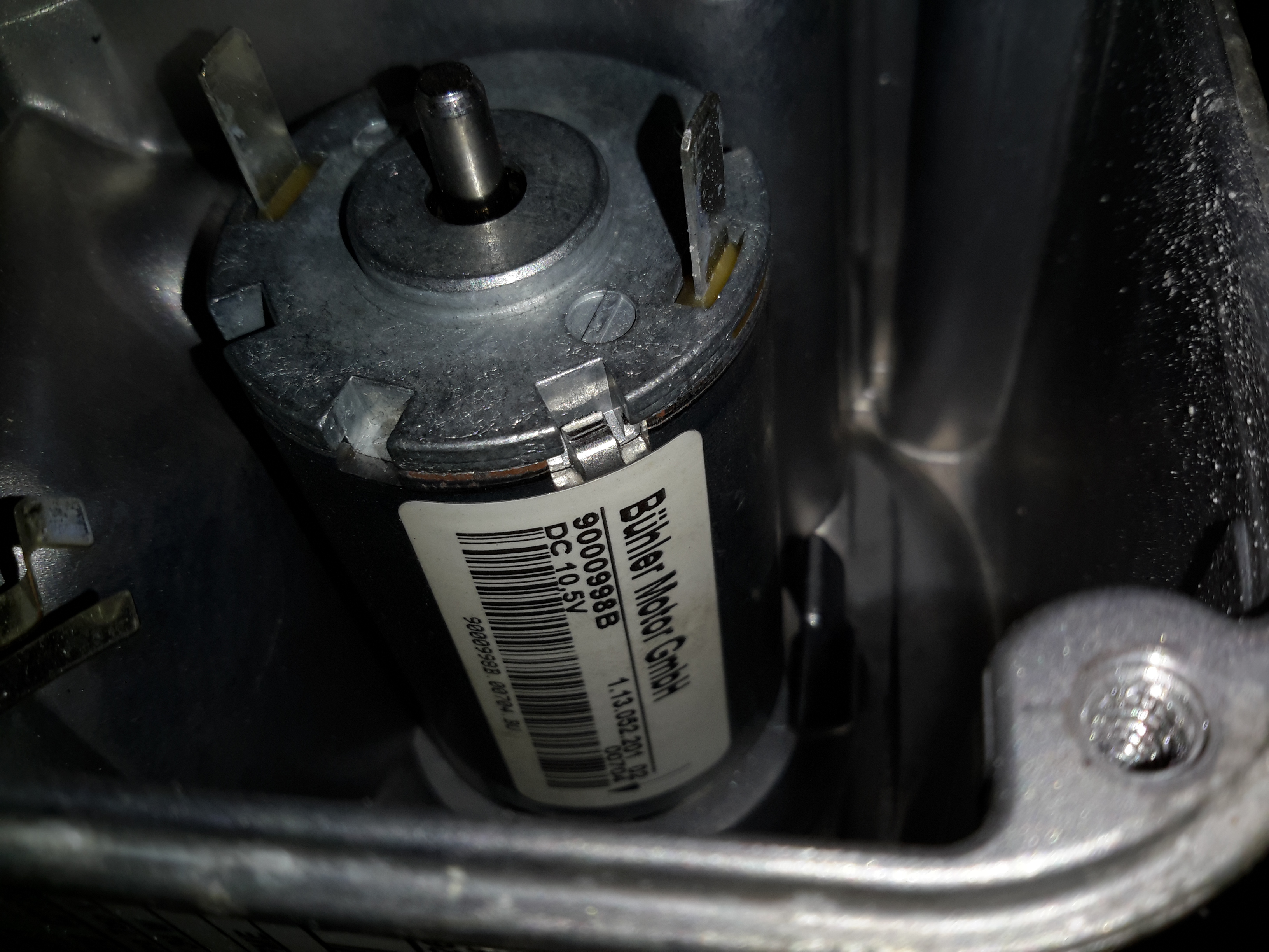
Combustion Fan Motor
The combustion fan motor is in the ECU compartment, nicely sealed away from the elements. There is no speed sensor on these blowers, unlike the Eberspacher ones.
Motor Details
The motor is a Buhler, rated at 10.5v.
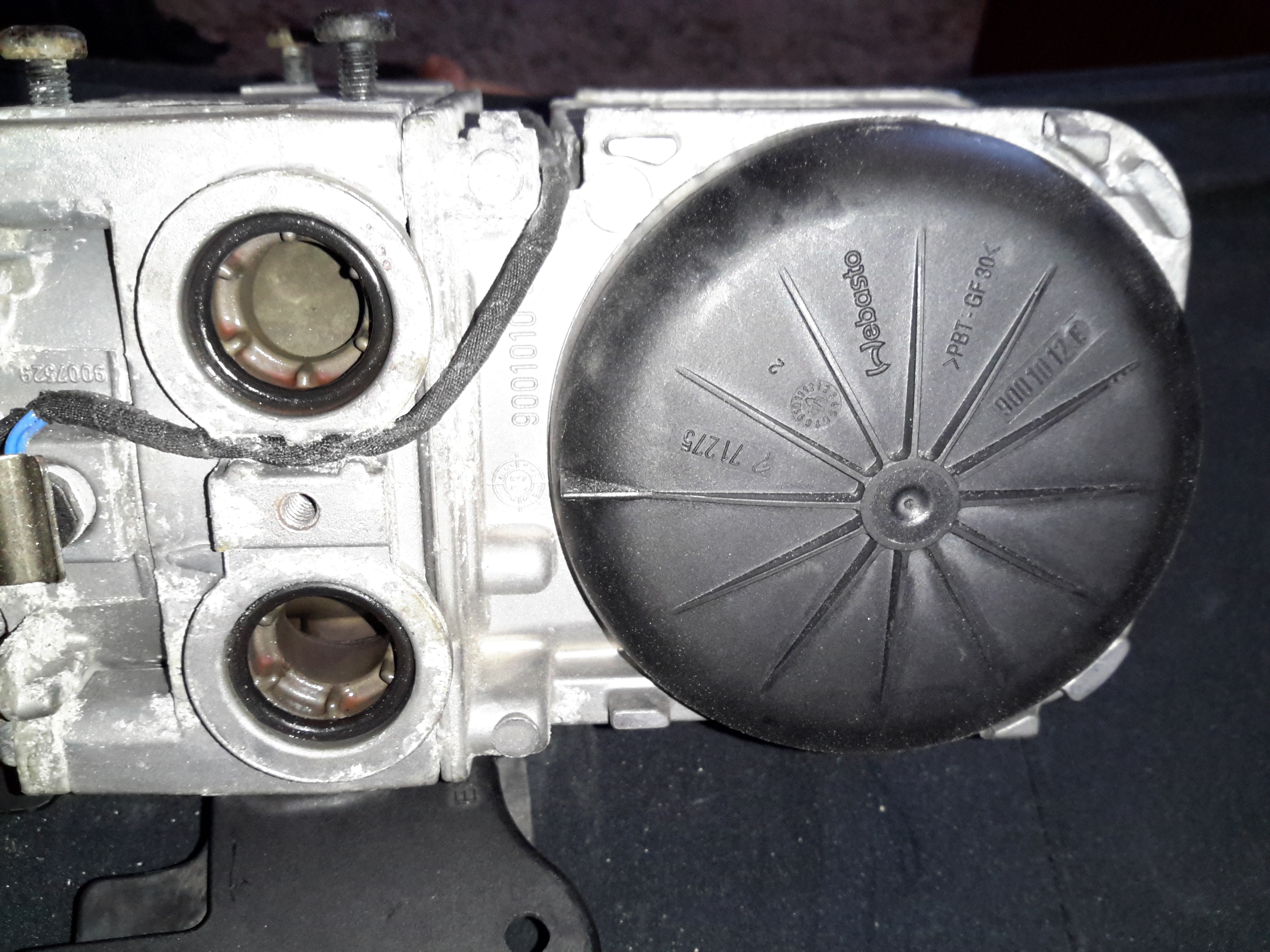
Water Ports & Combustion Fan Cover
Unclipping the cover from the other end reveals the combustion fan, it’s under the black cover. (These are side-channel blowers, to provide the relatively high static pressure required to run the burner).
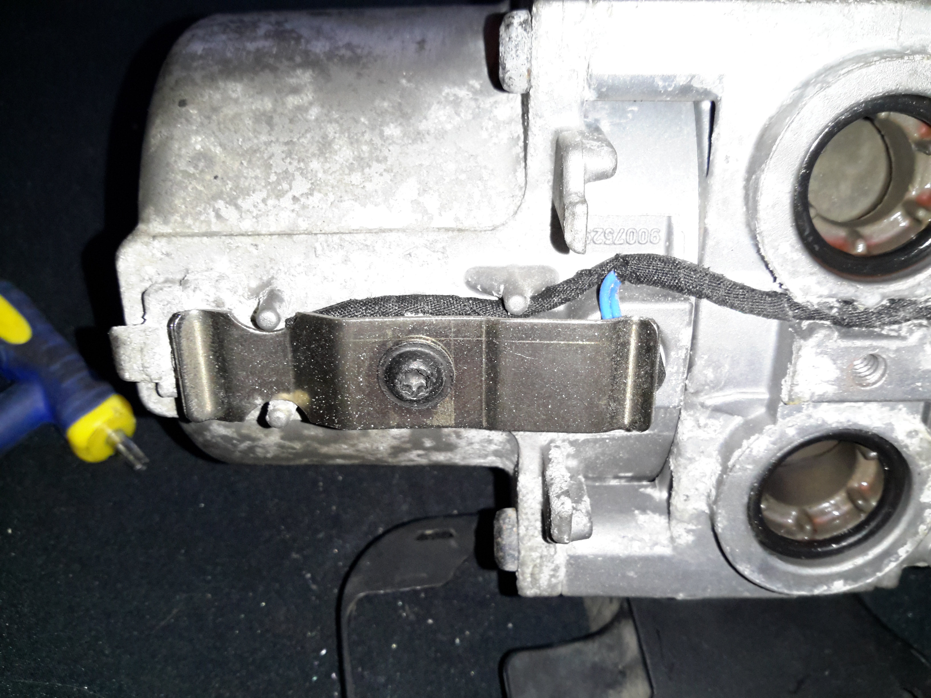
Sensor Clip
The overheat & temperature sensors are on the end of the heat exchanger, retained by a stainless clip.
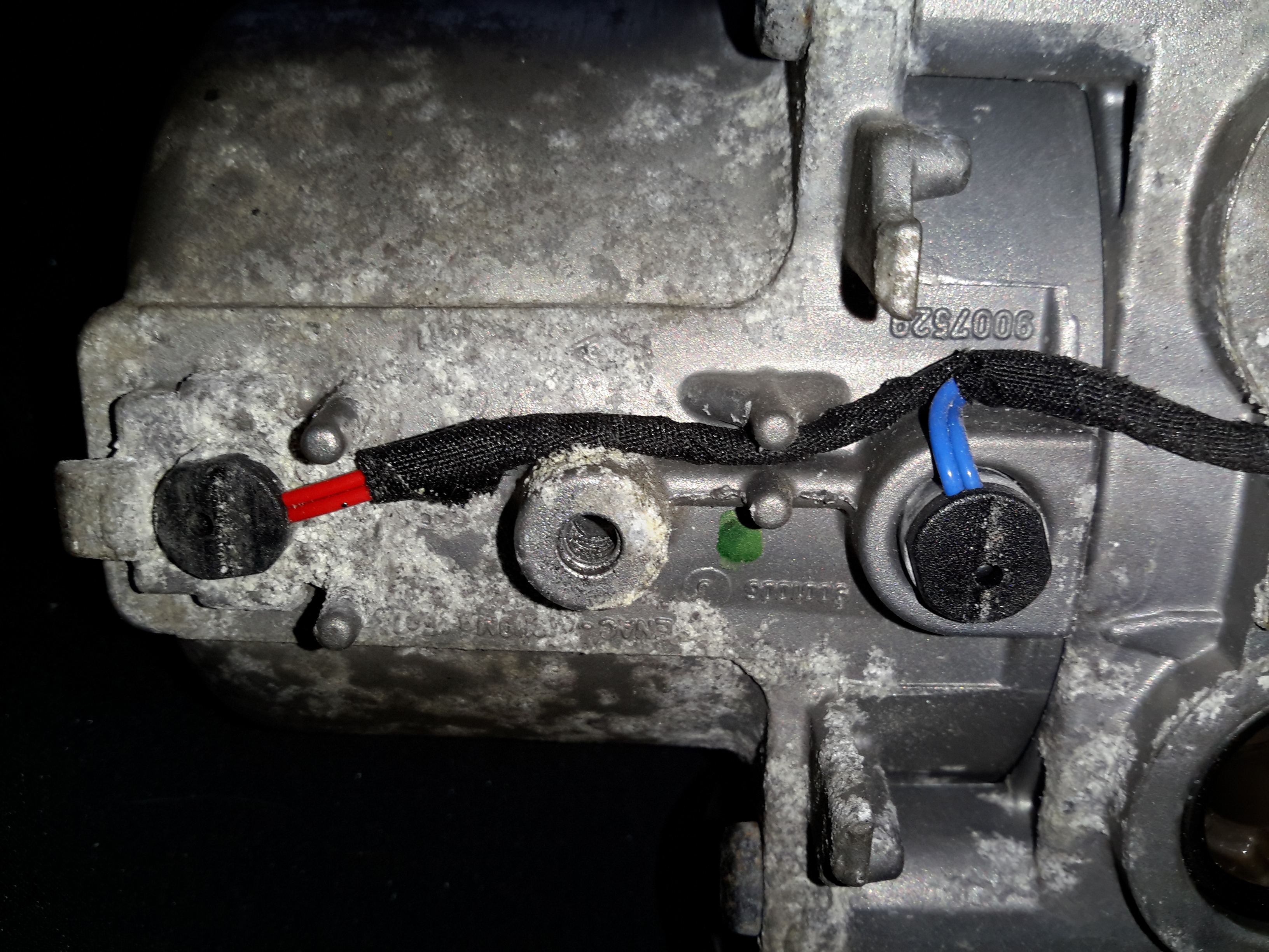
Temp & Overheat Sensors
With the clip removed, the sensors can be seen better. There’s some pretty bad corrosion of the aluminium alloy on the end sensor, it’s seized in place.
Burner
The heater splits in half to reveal the evaporative burner itself. I’ve already cleaned the black crud off with a wire brush here, doesn’t look like this heater has seen much use as it’s pretty clean inside.
Burner Chamber
Inside the burner the fuel evaporates & is ignited. There is a brass mesh behind the backplate of the burner to assist with vaporisation.
Glow Plug
The glow plug is fitted into the side of the burner ceramic here. This is probably a Silicon Carbide device. It also acts as a flame sensor when the heater has fired up. The fuel inlet line is to the left under the clamp.
Heat Exhanger
The hot gases from the burner flow into the heat exchanger here, with many fins to increase the surface area. There’s only a couple of mm coating of carbon here, after 10 years on the car I would have expected it to be much more clogged.
I’m currently waiting on some components to build an interface so I can get the Webasto Thermo Test software to talk to the heater. Once this is done I can see if there are any faults logged that need sorting before I can get this heater running, but from the current state it seems to be pretty good visually. More to come once parts arrive!
The full service manual for these heaters can be grabbed from here, along with the wiring details for the Jaguar implementation & the Thermo Test software for talking to them:
Here’s a very common chip used in older LCD monitors. This converts the incoming VGA signal into LVDS for the panel itself.
gmZAN3 Die
The gmZAN3 is a graphics processing IC for Liquid Crystal Display (LCD) monitors at XGA resolution. It provides all key IC functions required for the highest quality LCD monitors. On-chip functions include
a high-speed triple-ADC and PLL, a high quality zoom and shrink scaling engine, an on-screen display (OSD) controller and digital color controls.
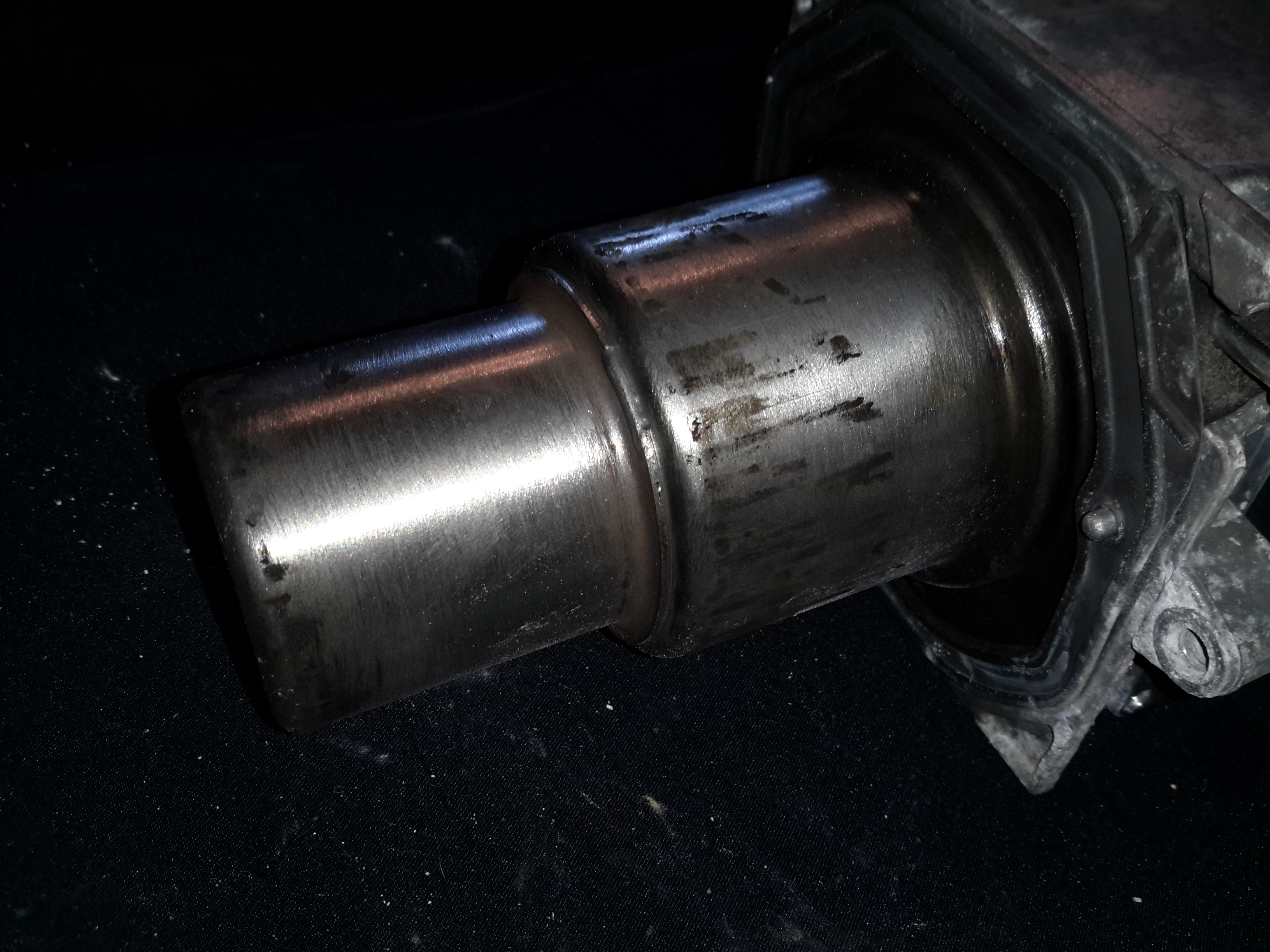
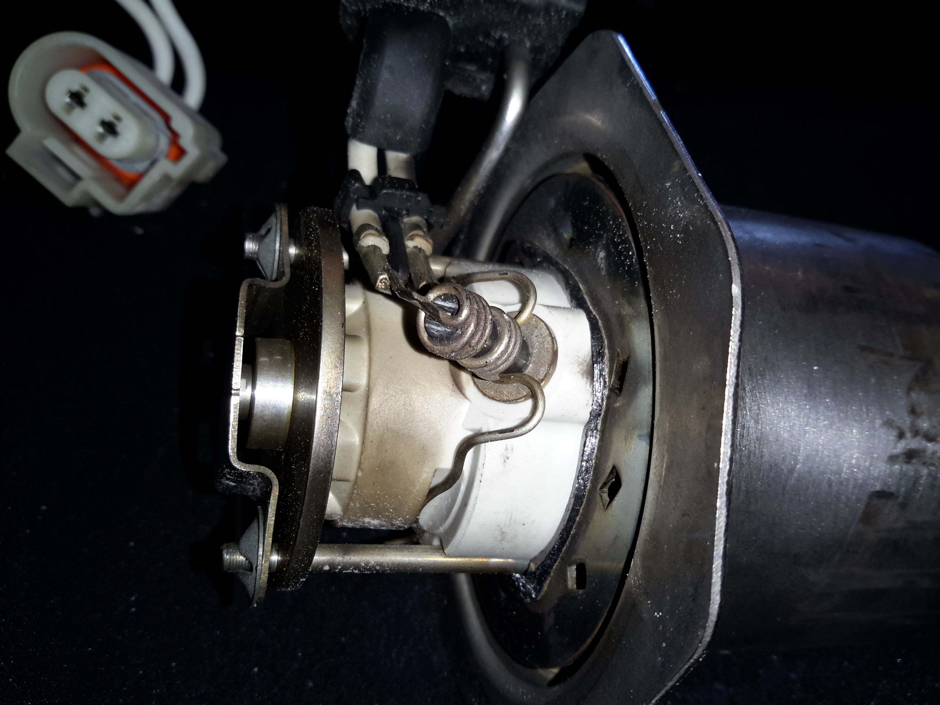
I wrote a few weeks ago about replacing the hot water circulating pump on the boat with a new one, and mentioned that we’d been through several pumps over the years. After every replacement, autopsy of the pump has revealed the failure mode: the first pump failed due to old age & limited life of carbon brushes. The second failed due to thermal shock from an airlock in the system causing the boiler to go a bit nuts through lack of water flow. The ceramic rotor in this one just cracked.
The last pump though, was mechanically worn, the pump bearings nicely polished down just enough to cause the rotor to stick. This is caused by sediment in the system, which comes from corrosion in the various components of the system. Radiators & skin tanks are steel, engine block cast iron, back boiler stainless steel, Webasto heat exchanger aluminium, along with various bits of copper pipe & hose tying the system together.
The use of dissimilar metals in a system is not particularly advisable, but in the case of the boat, it’s unavoidable. The antifreeze in the water does have anti-corrosive additives, but we were still left with the problem of all the various oxides of iron floating around the system acting like an abrasive. To solve this problem without having to go to the trouble of doing a full system flush, we fitted a magnetic filter:
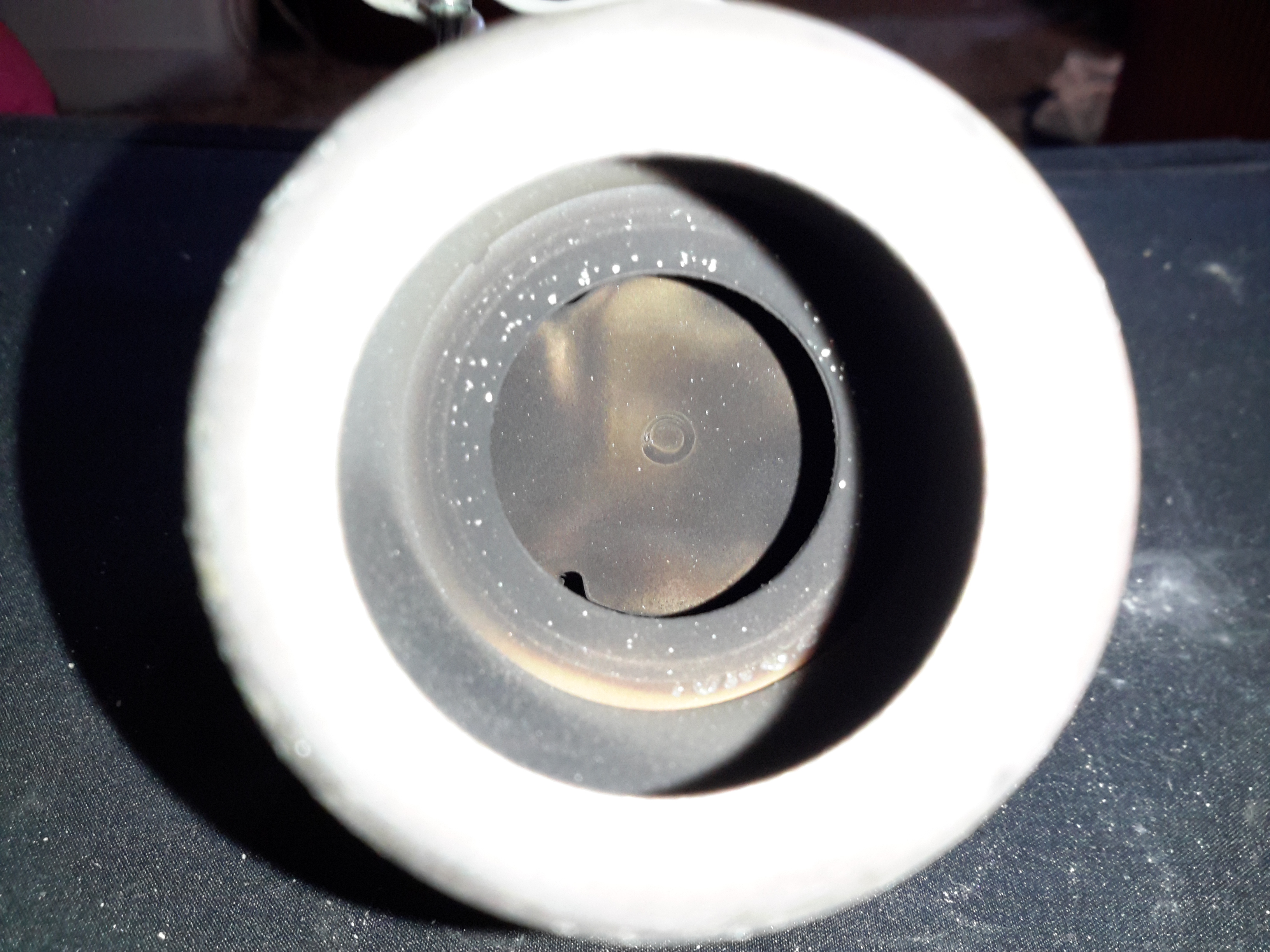
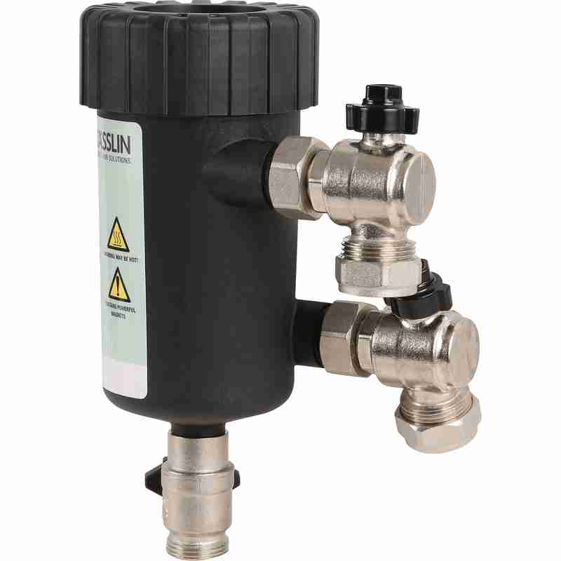
Mag Filter
This is just an empty container, with a powerful NdFeB magnet inserted into the centre. As the water flows in a spiral around the magnetic core, aided by the offset pipe connections, the magnet pulls all the magnetic oxides out of the water. it’s fitted into the circuit at the last radiator, where it’s accessible for the mandatory maintenance.
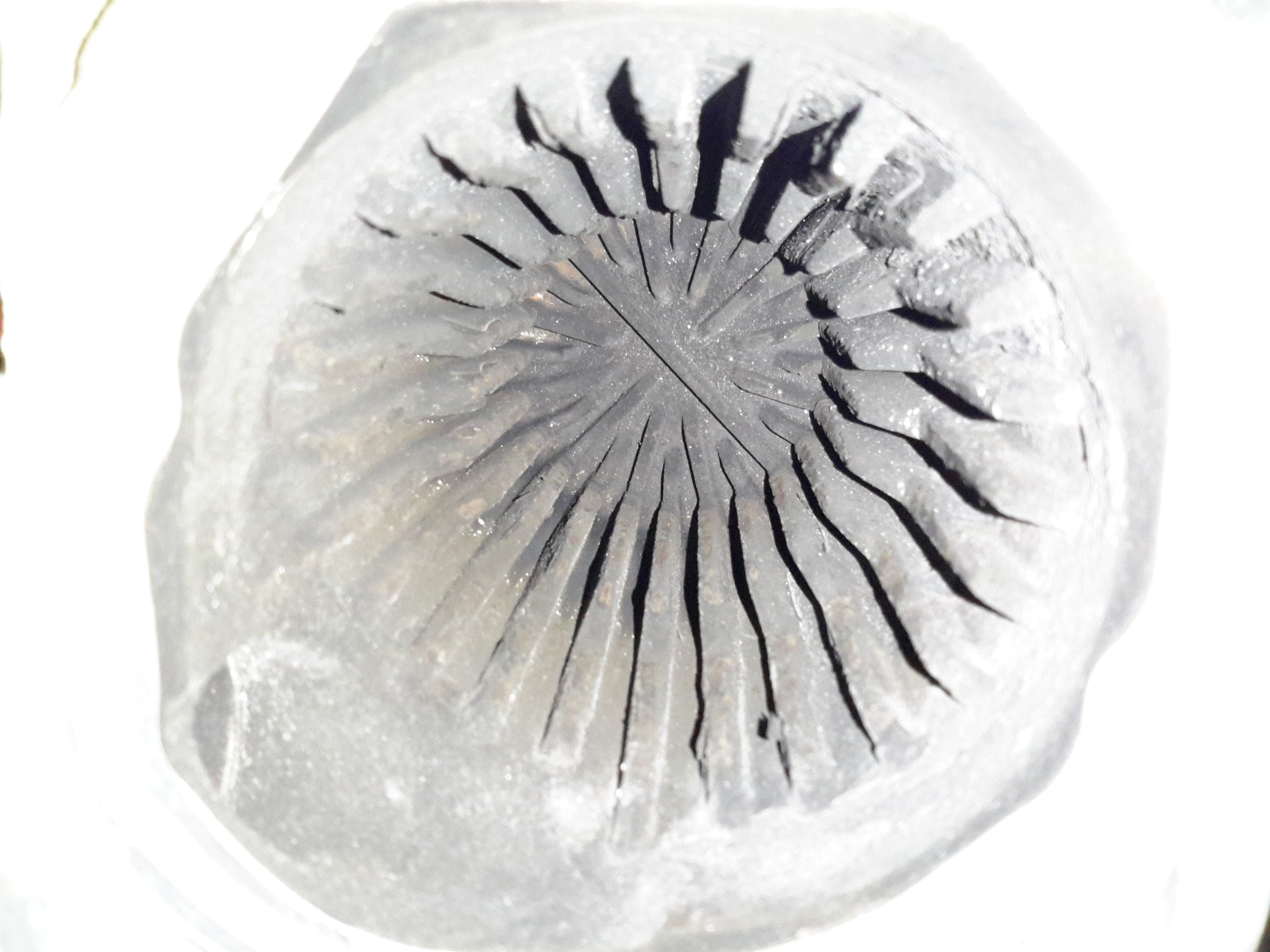
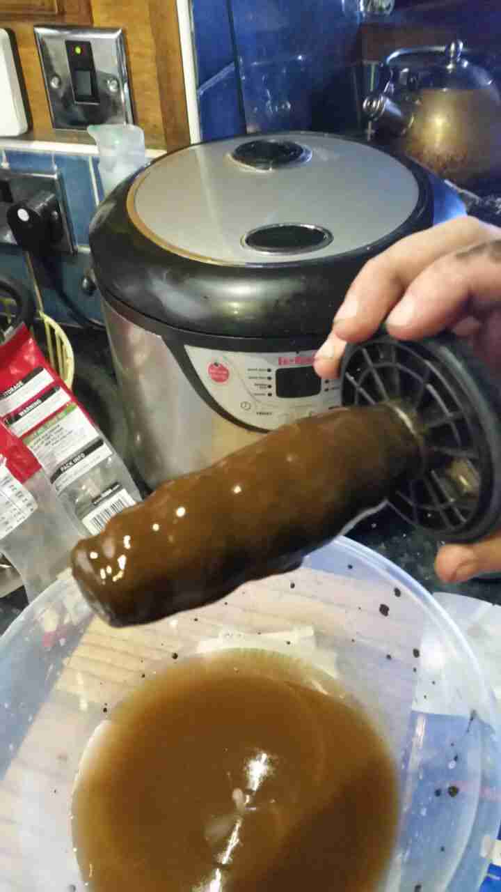
Sludge
Now the filter has been in about a month, I decided it would be a good time to see how much muck had been pulled out of the circuit. I was rather surprised to see a 1/2″ thick layer of sludge coating the magnetic core! The disgusting water in the bowl below was what drained out of the filter before the top was pulled. (The general colour of the water in the circuit isn’t this colour, I knocked some loose from the core of the filter while isolating it).
If all goes well, the level of sludge in the system will over time be reduced to a very low level, with the corrosion inhibitor helping things along. This should result in much fewer expensive pump replacements!
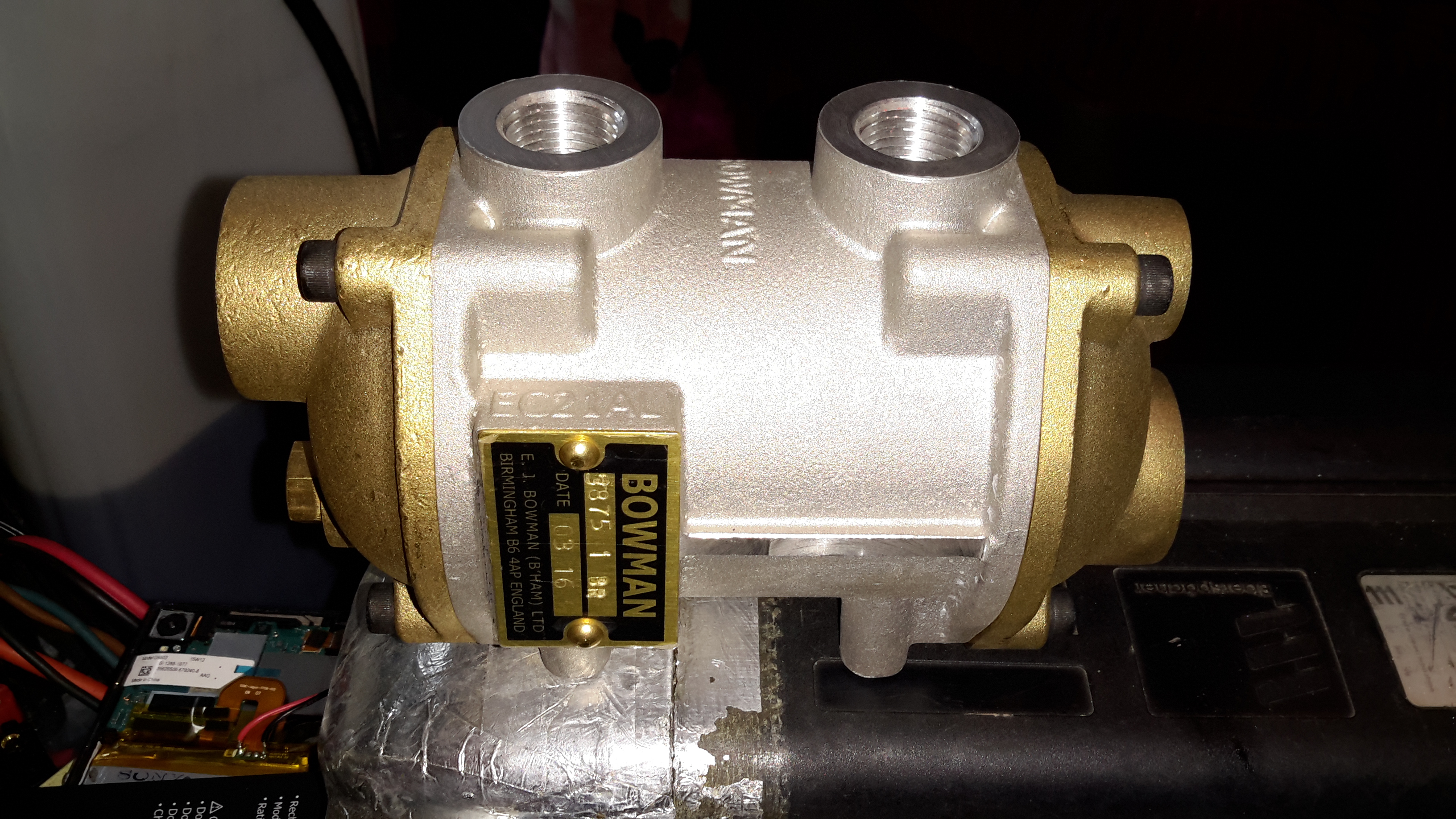
To solve some engine oil overheating problems on board nb Tanya Louise, we decided to replace the air-over-oil cooler, with an water-over-oil cooler, with separate cooling drawn straight from the canal, as the skin tanks are already overloaded with having to cope with not only cooling the engine coolant, but also the hydraulic system oil as well.
These units aren’t cheap in the slightest, but the construction quality & engineering is fantastic.
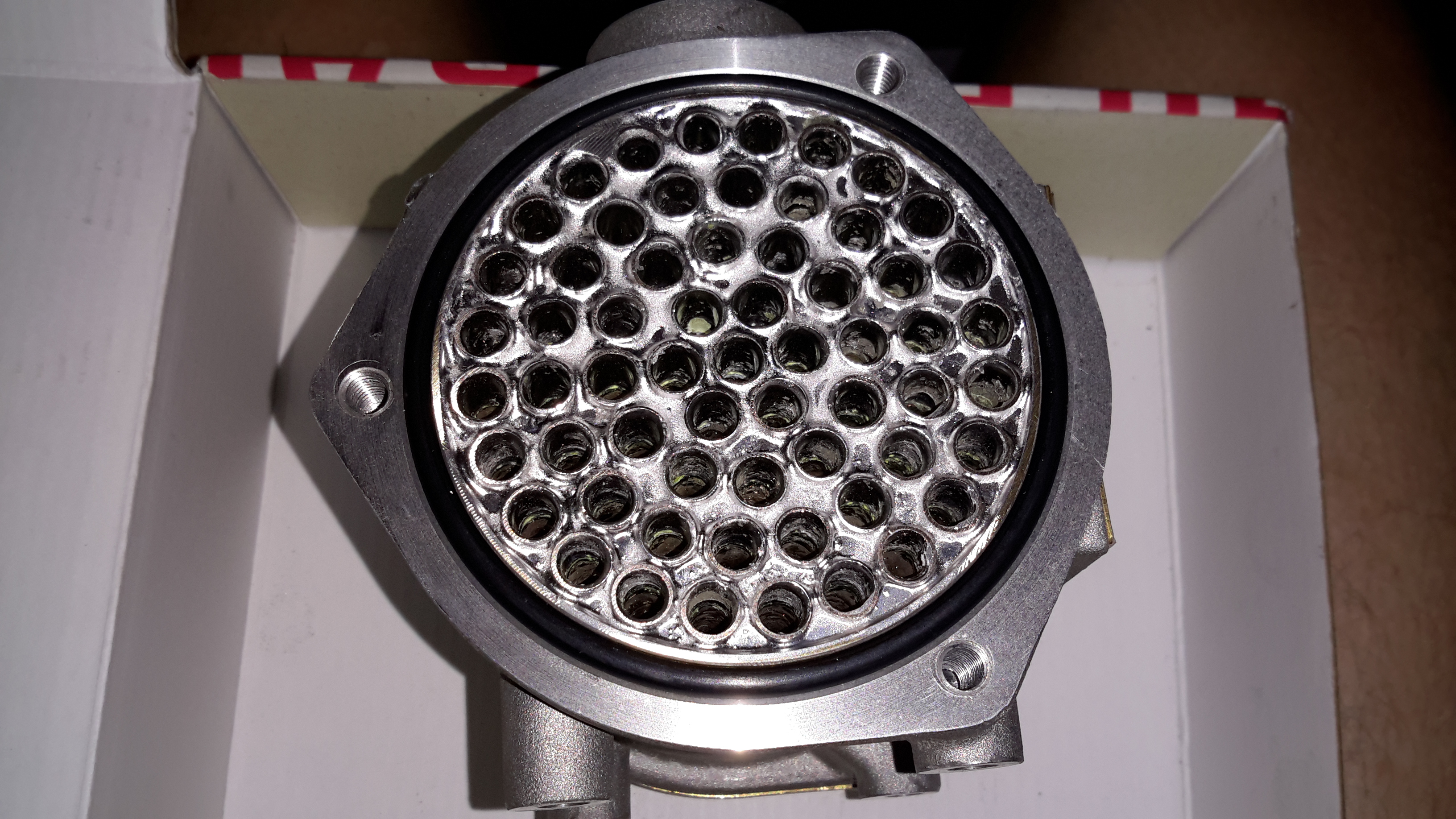
Tube End Plate
Unbolting the end cover reveals the brass tube end plate, soldered to all the core tubes in the cooler. An O-Ring at each end seals both the end cover & the interface between the tube plate & the outer casing.
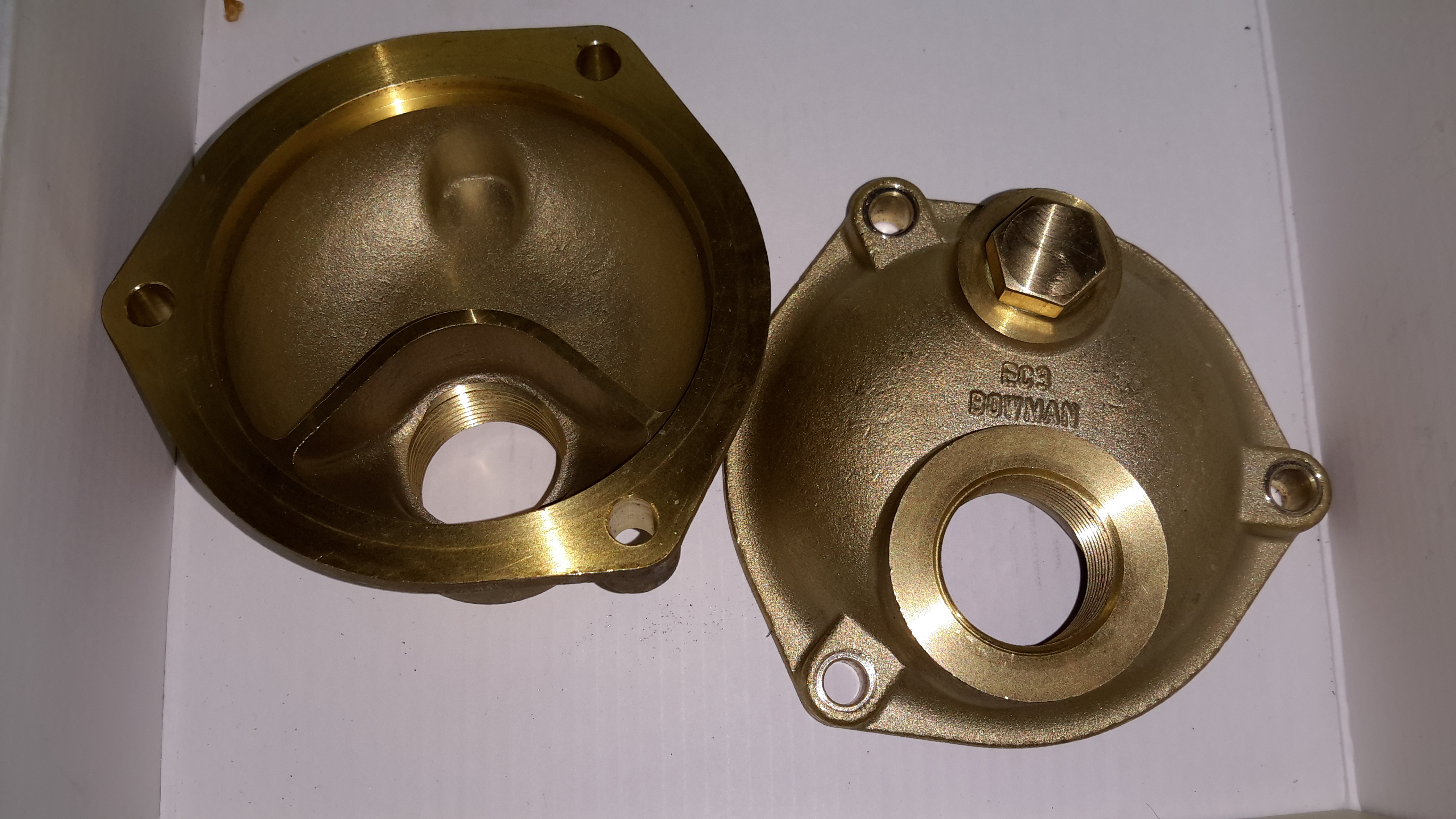
End Caps
The end caps have baffles cast in to direct the cooling water in a serpentine path, so the oil gets the best chance at dissipating it’s heat to the water.
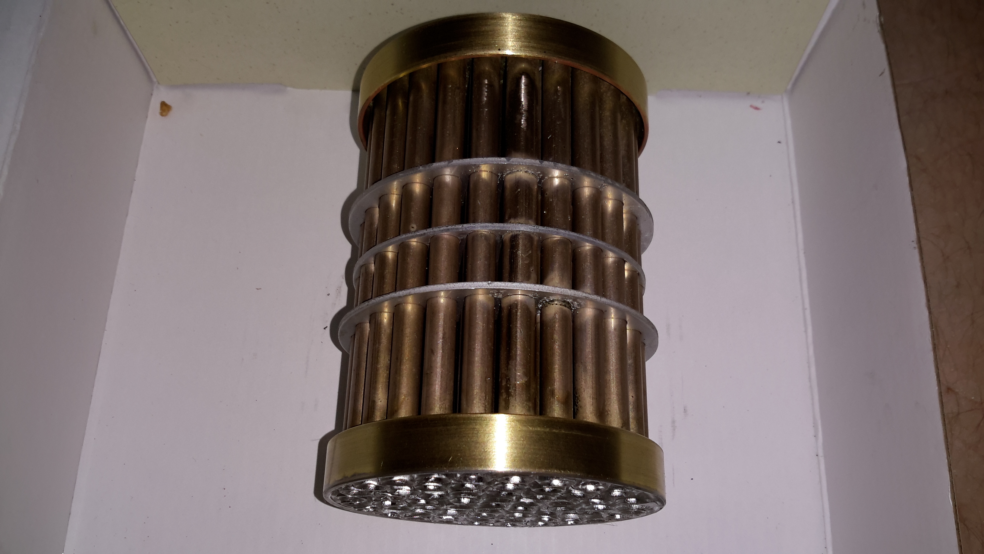
Tube Stack
The oil side of the system is on the outside of the tubes, again baffles placed along the stack direct the oil over the highest surface area possible.
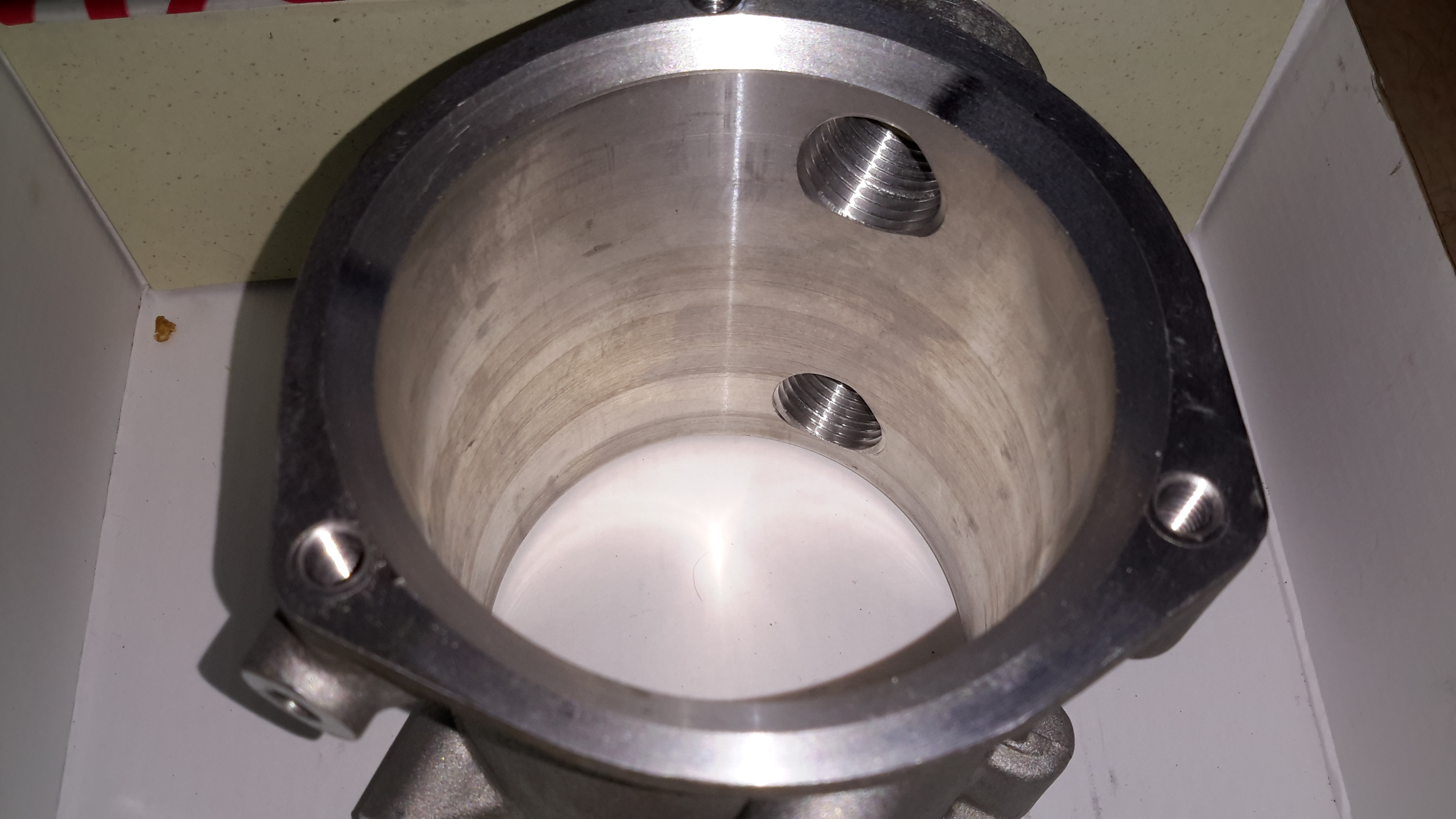
Outer Shell
The outer shell is just a machined alloy casting, with no internal features.
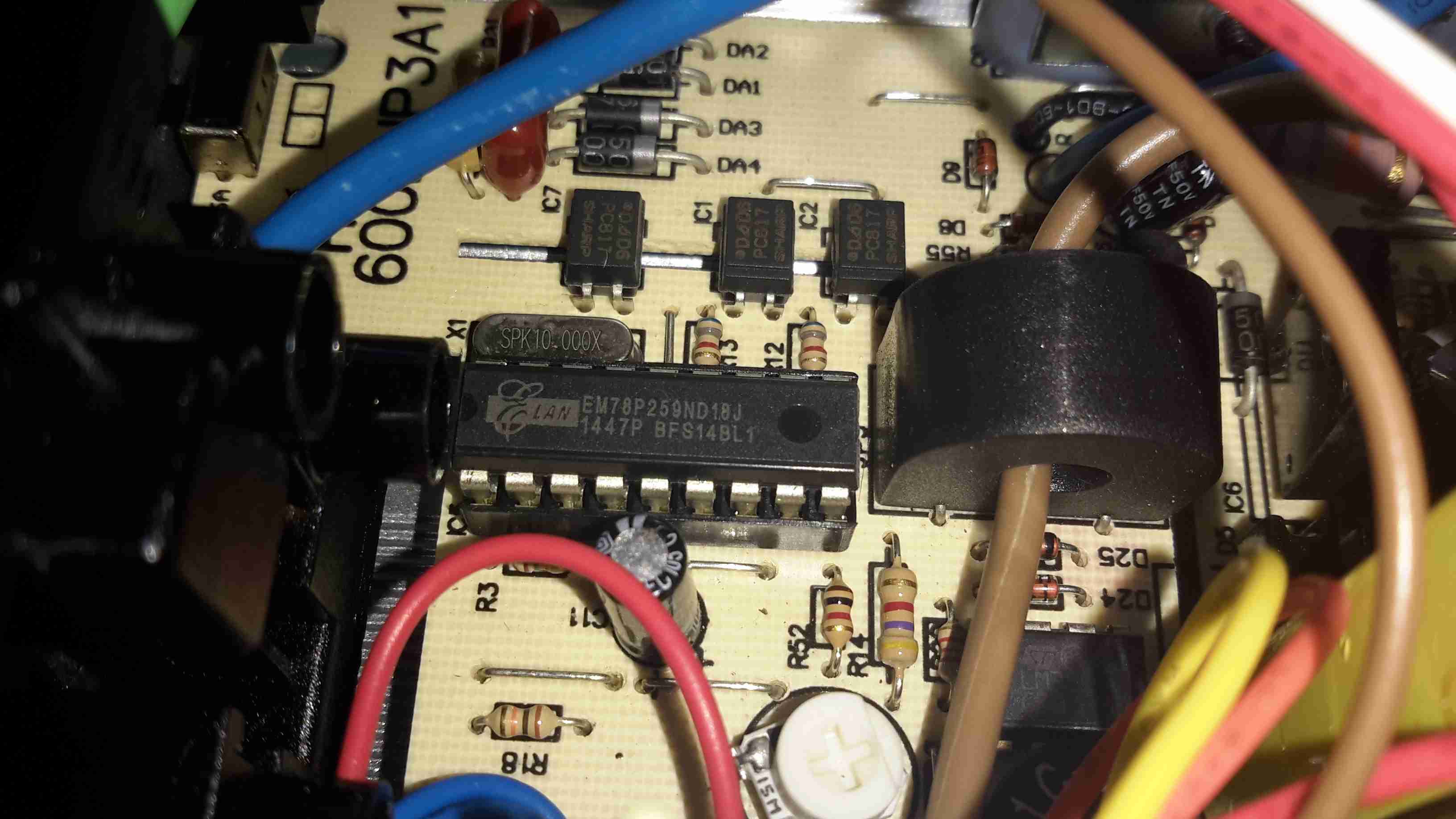
I’m no fan of power inverters. In my experience they’re horrifically inefficient, have power appetites that make engine starter motors look like electric toothbrushes & reduce the life expectancy of lead-acid batteries to no more than a few days.
However I have decided to do a little analysis on a cheapo “600W” model that Maplin Electronics sells.
Cover Removed
After a serious amount of metallic abuse, the bottom cover eventually came off. The sheet of steel used to close the bottom of the aluminium extrusion was wedged into place with what was probably a 10 ton hydraulic press.
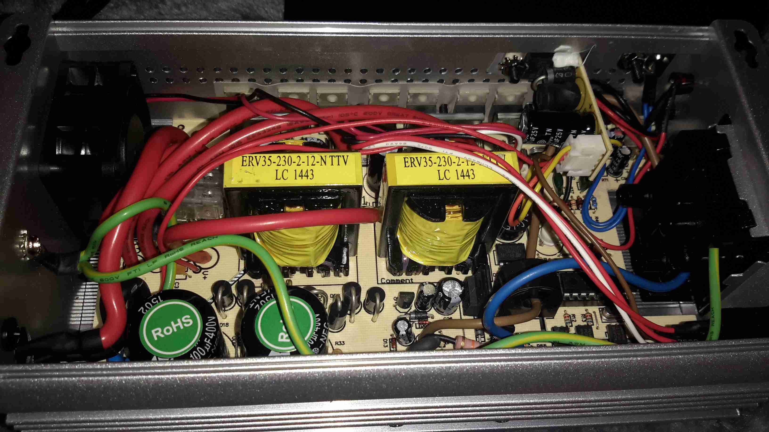
As can be seen from the PCB, there’s no massive 50Hz power transformer, but a pair of high frequency switching transformers. Obviously this is to lighten the weight & the cost of the magnetics, but it does nothing for the quality of the AC output waveform.
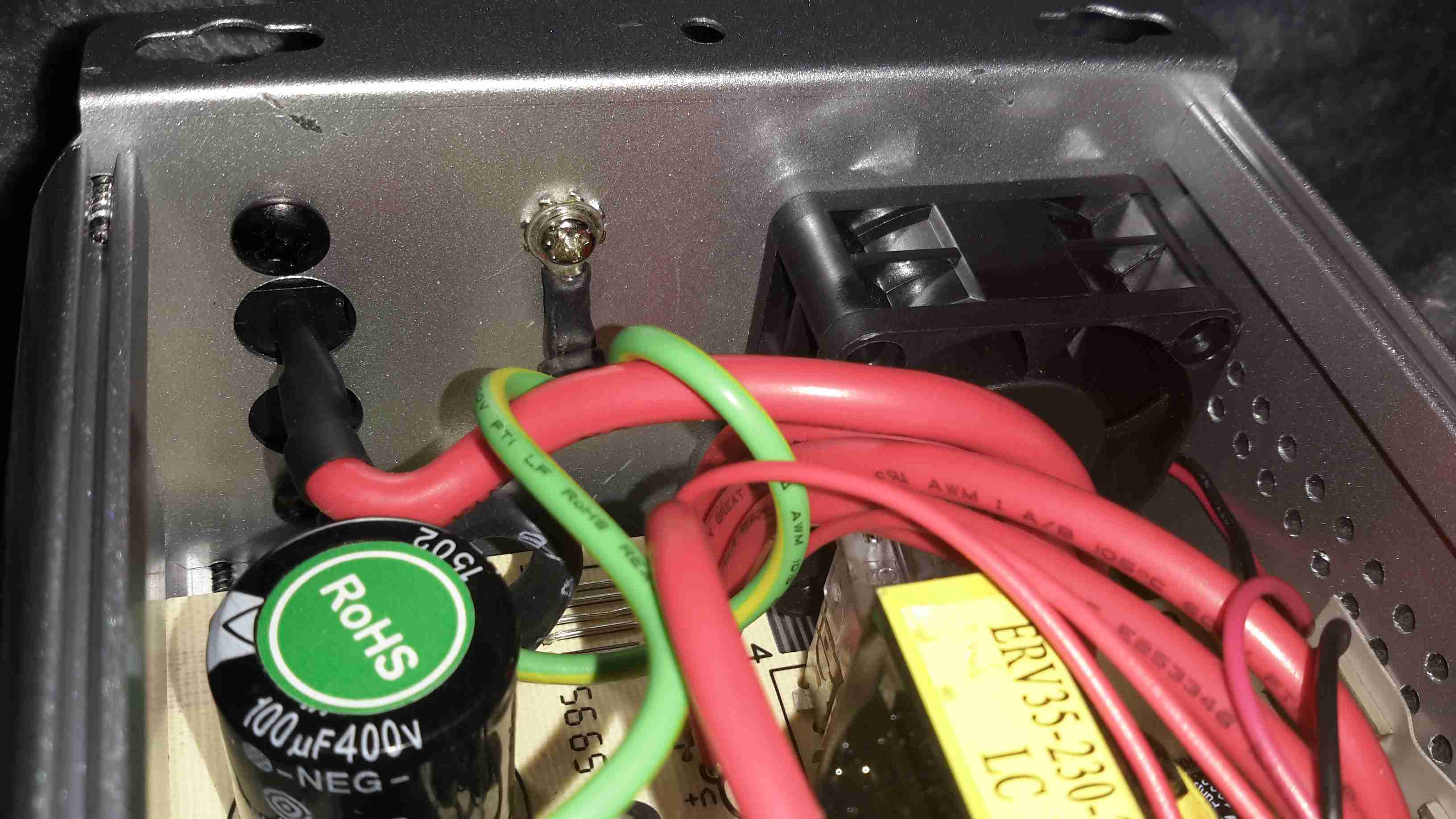
DC Input End
The 12v DC from the battery comes in on very heavy 8-gauge cables, this device is fused at 75A!
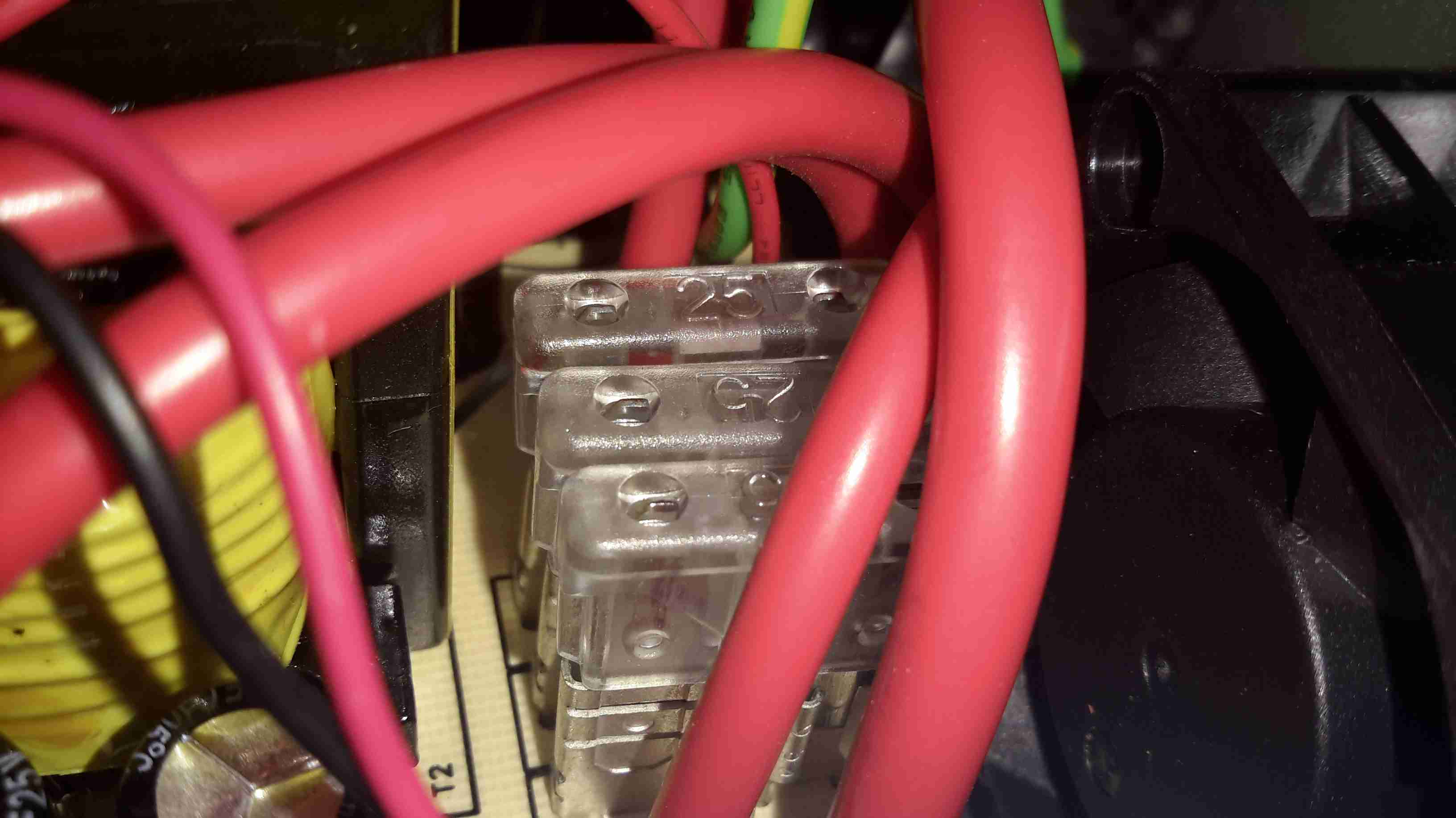
DC Fuses
Here’s the fusing arrangement on the DC input stage, just 3 standard blade-type automotive fuses. Interestingly, these are very difficult to get at without a large hammer & some swearing, so I imagine if the user manages to blow these Maplin just expect the device to be thrown out.
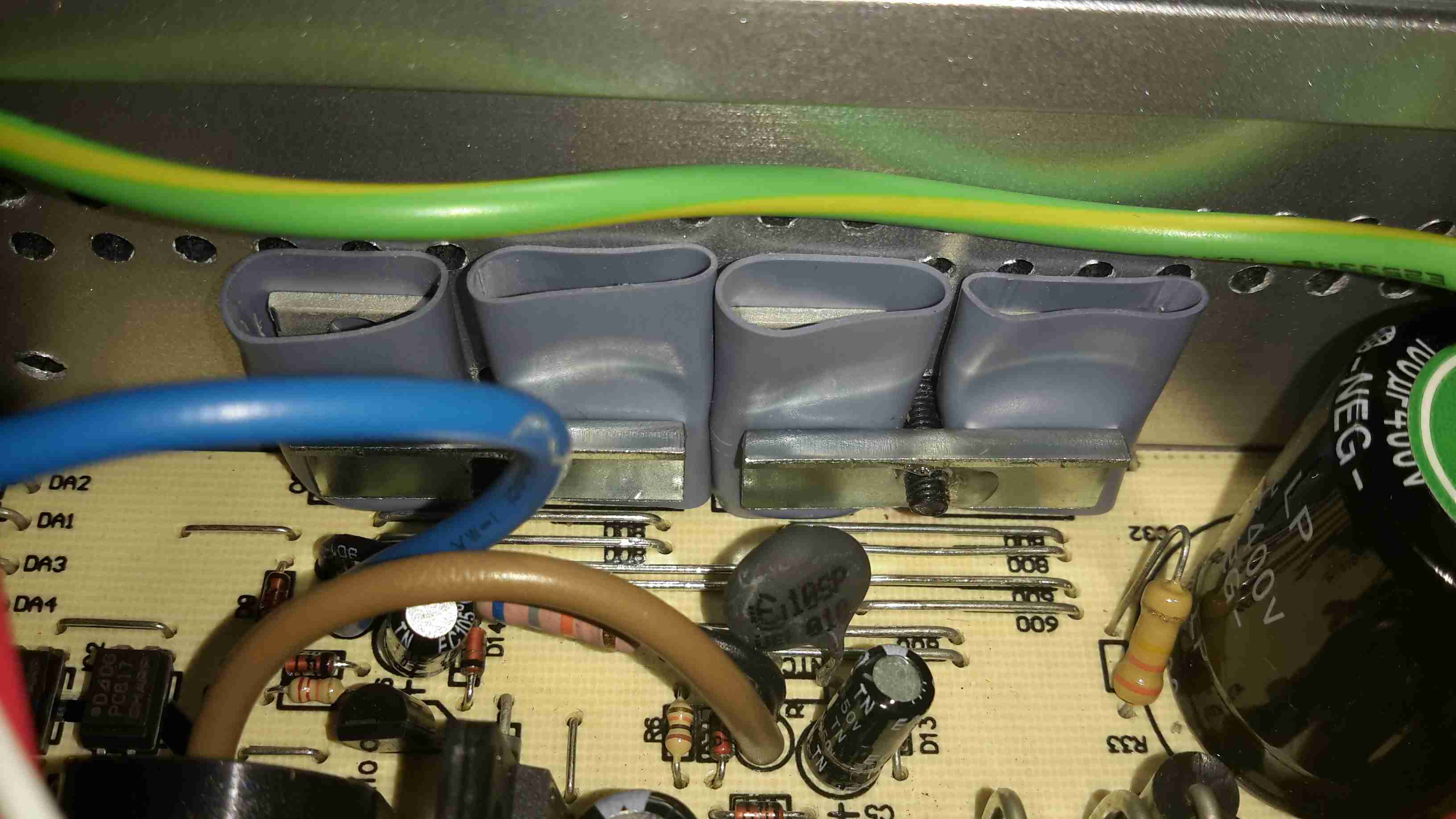
Input DC-DC Switching MOSFETs
On the input side, the DC is switched into the pair of transformers to create a bipolar high voltage DC supply.
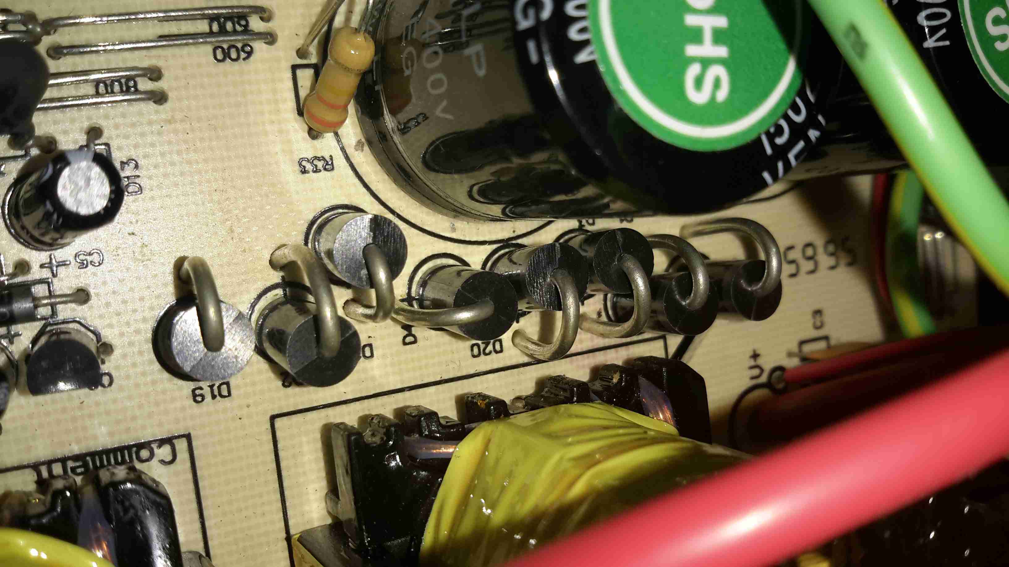
High Voltage Rectifiers
The large rectifier diodes on the outputs of the transformers feed into the 400v 100µF smoothing capacitors.
As mains AC is obviously a bipolar waveform, I’m guessing this is generating a ±150v DC supply.
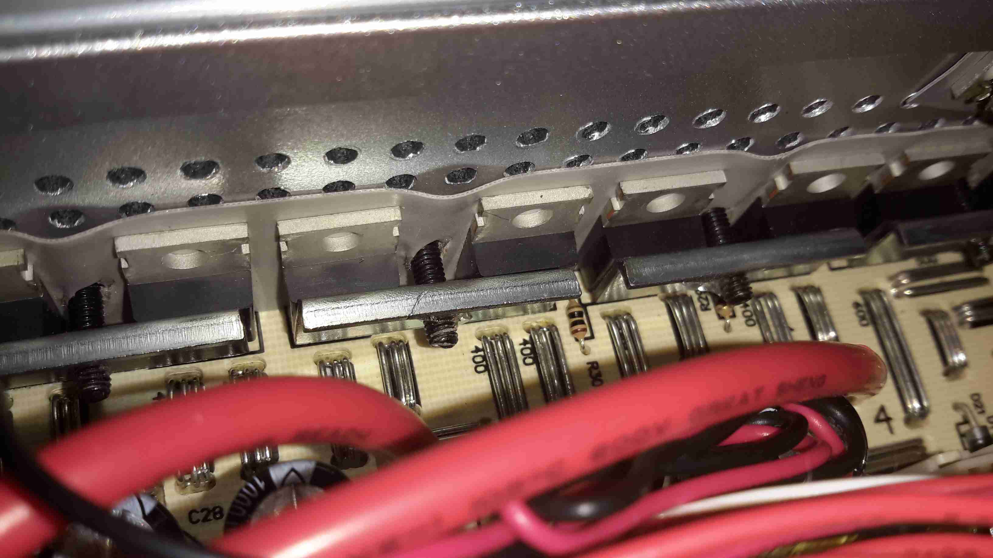
Output MOSFETs
After the high voltage is rectified & smoothed, it’s switched through 4 more MOSFETs on the other side of the PCB to create the main AC output.
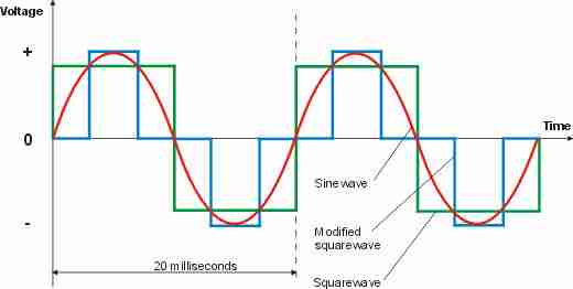
The label states this is a modified-sine output, so I’d expect something on the scope that looks like this:
Inverter Waveforms
Modified-sine doesn’t look as bad as just a pure square output, but I suspect it’s a little hard on inductive loads & rectifiers.
However, after connecting the scope, here’s the actual waveform:
Actual Waveform
It’s horrific. It’s not even symmetrical. There isn’t even a true “neutral” either. The same waveform (in antiphase) is on the other mains socket terminal. This gives an RMS output voltage of 284v. Needless to say I didn’t try it under load, as I don’t possess anything I don’t mind destroying. (This is when incandescent lamps are *really* useful. Bloody EU ;)).
About the only thing that it’s accurate at reproducing is the 50Hz output, which it does pretty damn well.
System Microcontroller
As is usual these days, the whole system is controlled via a microcontroller.
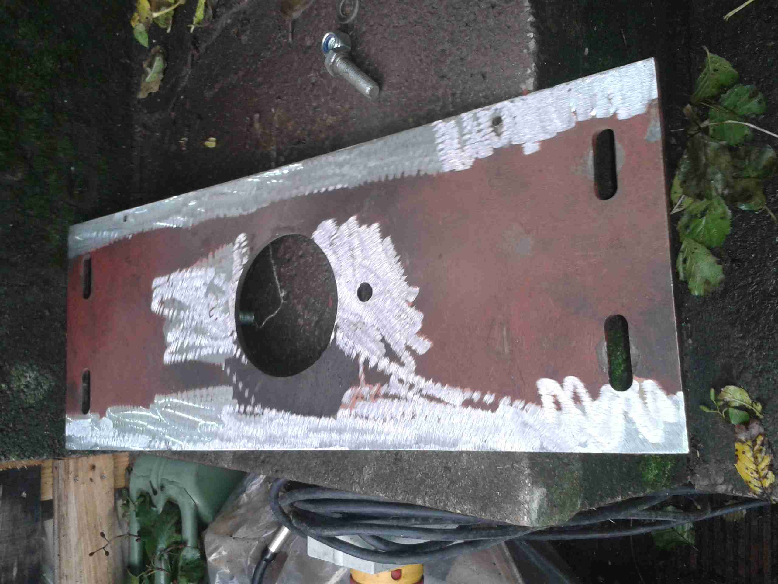
It’s time for the final part of getting the boat’s engine & drive back together, now I have the new coupling hub. I decided to address one of the issues with the pump mounting while I had everything in bits. When the hydraulic drive was installed, a custom plate was laser cut to fit the pump stack to, as we had no bellhousing with a standard mounting pattern.
Even though this plate is 10mm steel, under full load it actually bends – so to strengthen it along the long edge, I have welded a pair of ribs to the plate.
Pump Mounting Plate
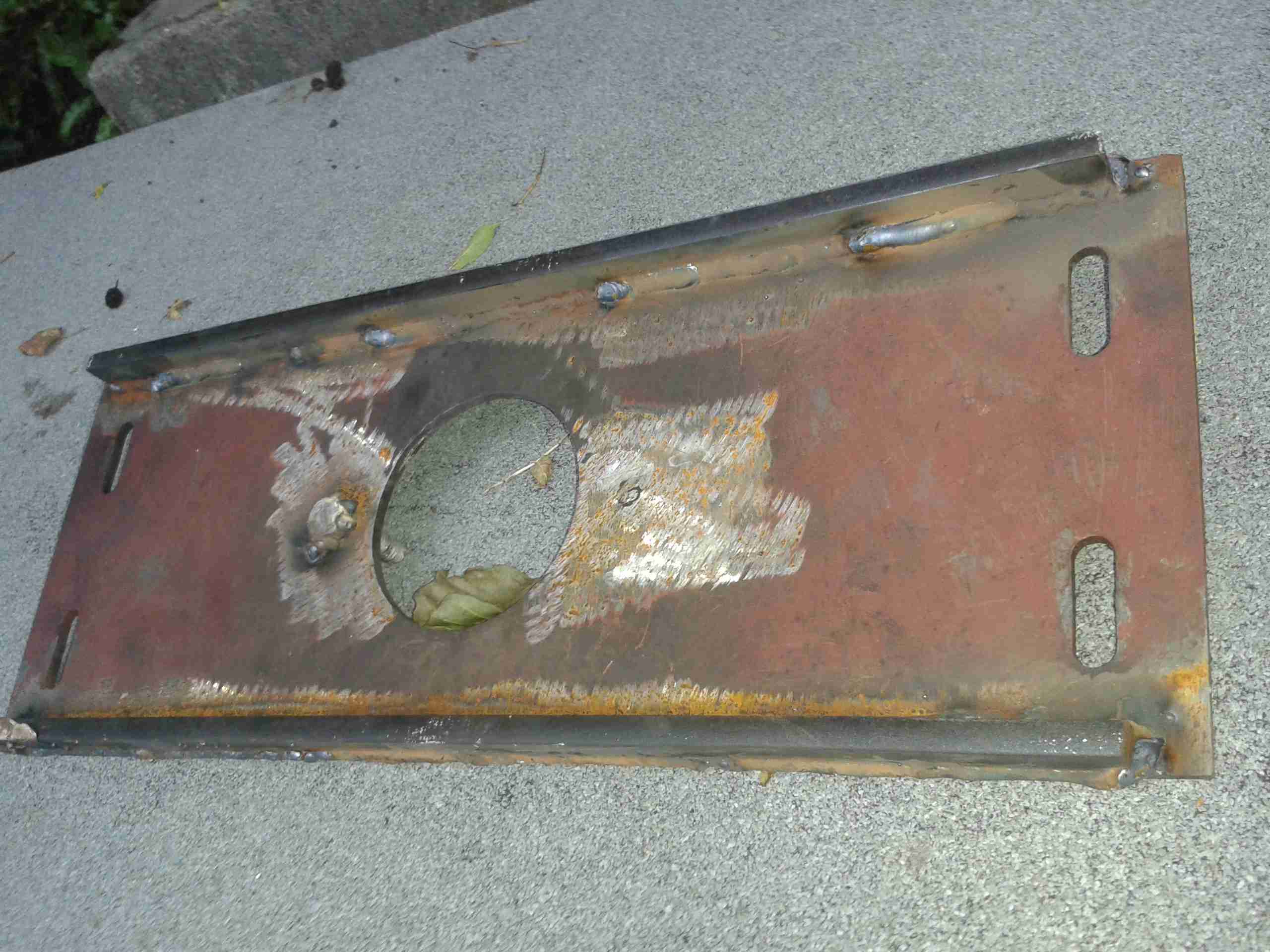
The mounting plate as removed from the mounting brackets. The slotted holes at the sides allow for some movement to adjust the position of the pump & flywheel coupling.
Prepared For Welding
I ground off the paint & grease with an abrasive disc, and am replacing one of the pump mounting studs while I’m at it.
Strengthening Ribs
Here’s the plate after welding. a pair of 10mm bars have been attached along the edges, this will give the mounting significantly more strength on the long axis & prevent any deformation.
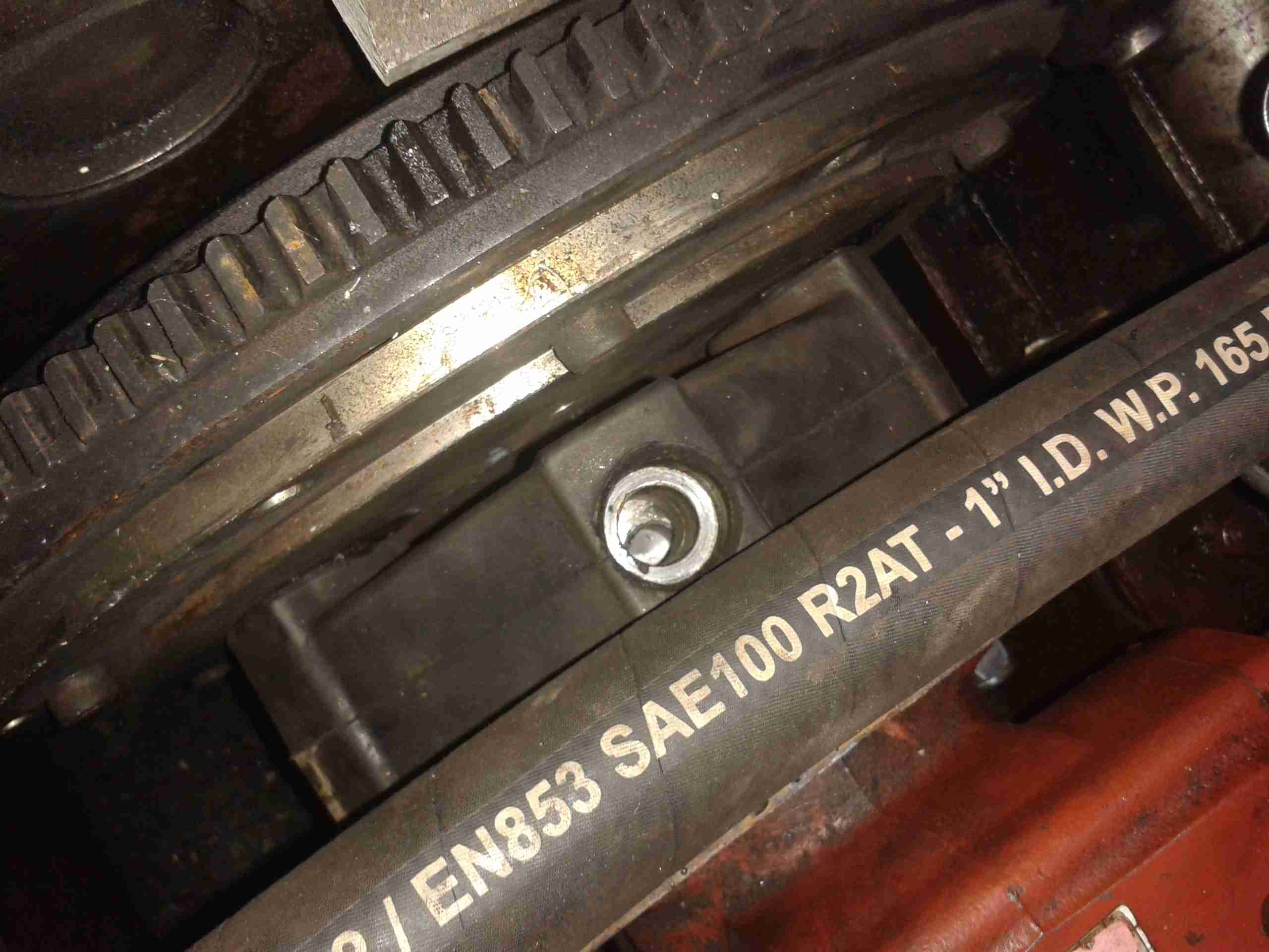
Pump On Hoist
Here the plate has been loosely mounted on it’s brackets, & I’ve got the pump stack with it’s associated tangle of hoses on the chain hoist. This unit is very heavy on it’s own – a 2 man job to lift it into place on it’s mounts – with the very stiff hydraulic hoses attached & filled with oil it’s absolutely unmanageable.
Lining Up The Mountings
Here the pump is being jostled into place. The central hole in the mounting plate is a very snug fit, if the pump doesn’t go in exactly straight it will jam & cause damage to both parts. The mating hole in the coupling hub can be seen here – it’s not quite lined up yet.
Almost There
We’ve got about 10mm to go before the pump is seated. It’s held in place with a pair of large studs & nuts.
Coupling Connected
Here the pump is fitted enough to get the main mounting bolts into the coupling. These are torqued down to 150ft/lbs – a difficult thing to do considering the restricted space in the engine bay.
Flush Mounting
The pump has been pulled down onto the plate evenly with the mounting studs, and is now completely flush with the plate. As can be seen, I didn’t bother tidying up the welds with a grinder, they aren’t in any visible place in normal operation, so it didn’t warrant the effort.
Pump Refitted
Finally, the control cable is reattached to the pump’s control lever & everything is installed! A short test trip proved that everything was stable & no undue movement of the pump or coupling was noticed.
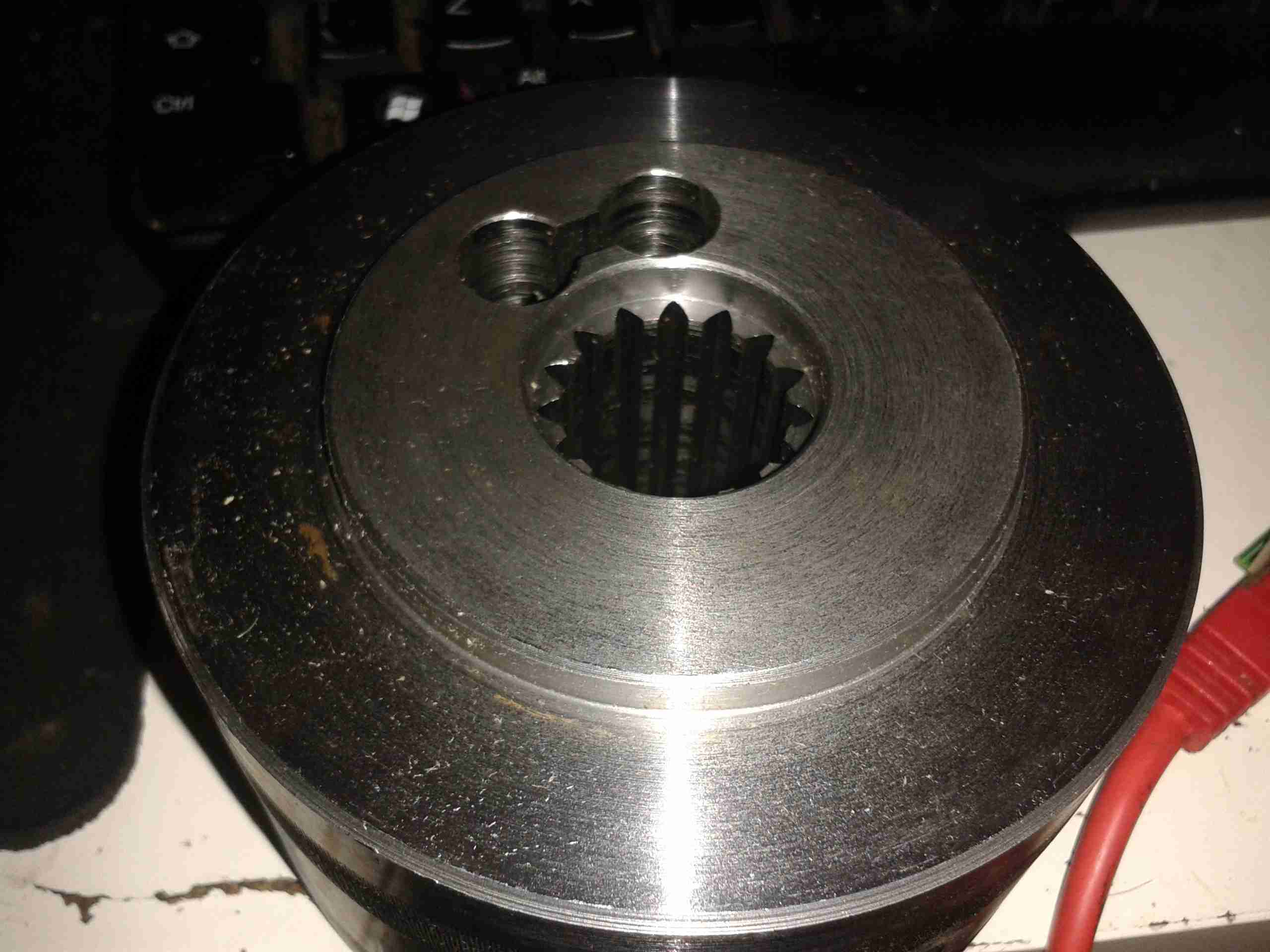
Time to get on with the job now the parts have arrived! Above is the new coupling hub, as can be seen compared to the old one that I previously posted about, this one has it’s full complement of splines.
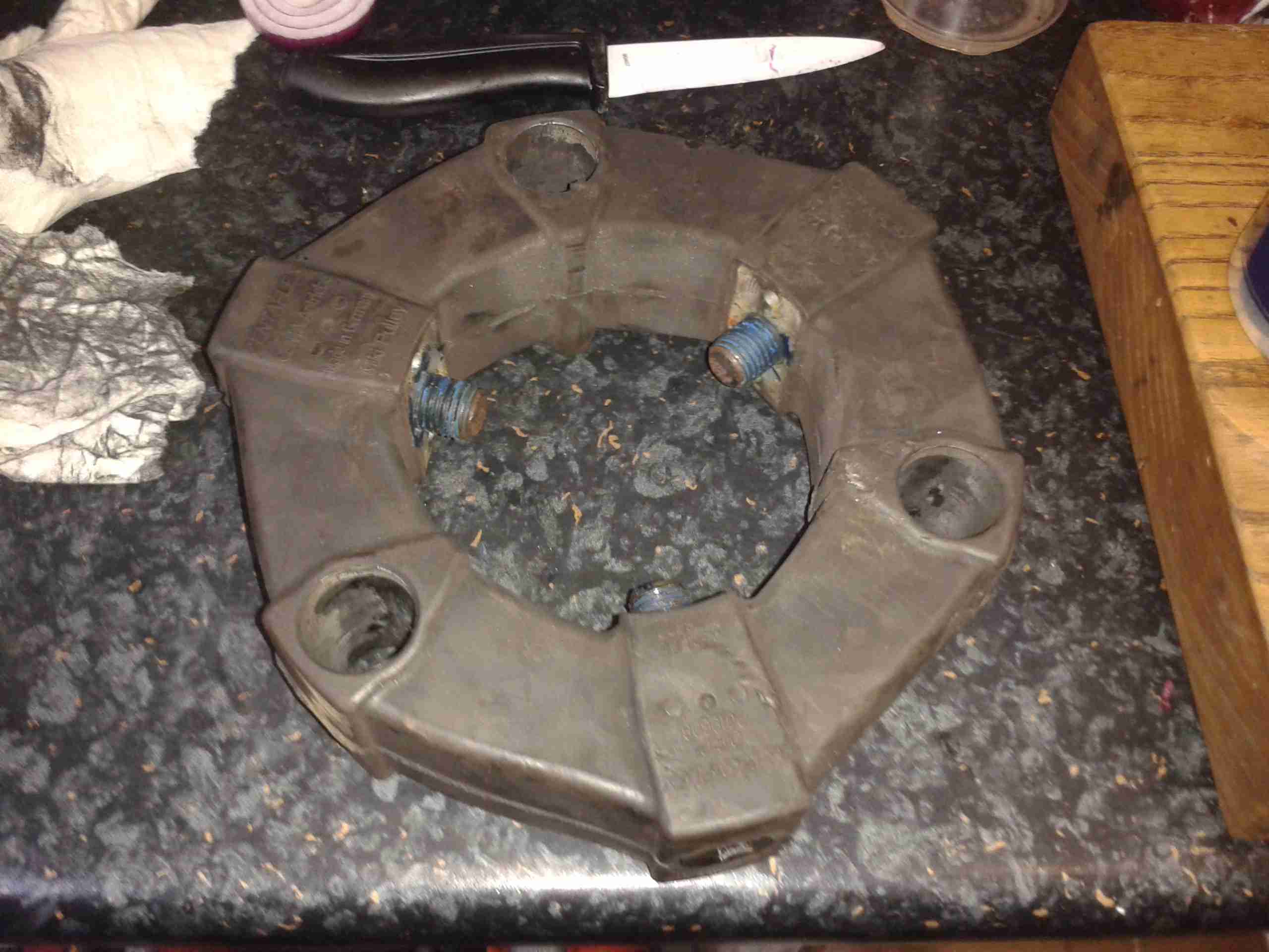
Rubber Element
The hub bolts into the centre of this rubber coupling, which itself locates on pins attached to the engine’s flywheel. This part wasn’t damaged so it’s being reused with the new hub.
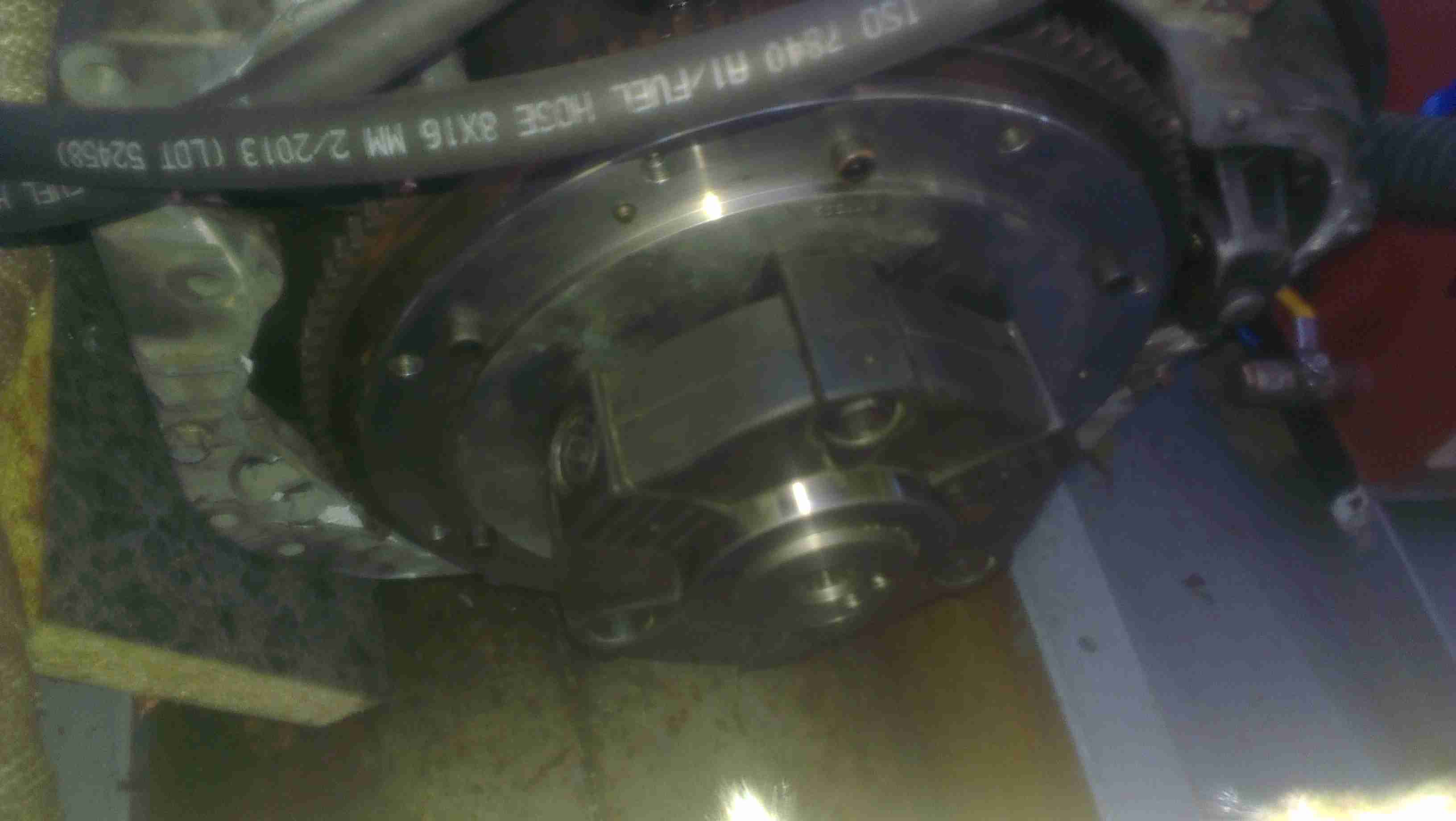
Hub Installed
Here’s the hub installed on the input shaft of the main hydraulic pump stack, the pair of holes on the side of the hub are for the grub screws that secure the coupling on the splines. These screws coming loose are what destroyed the old coupling.
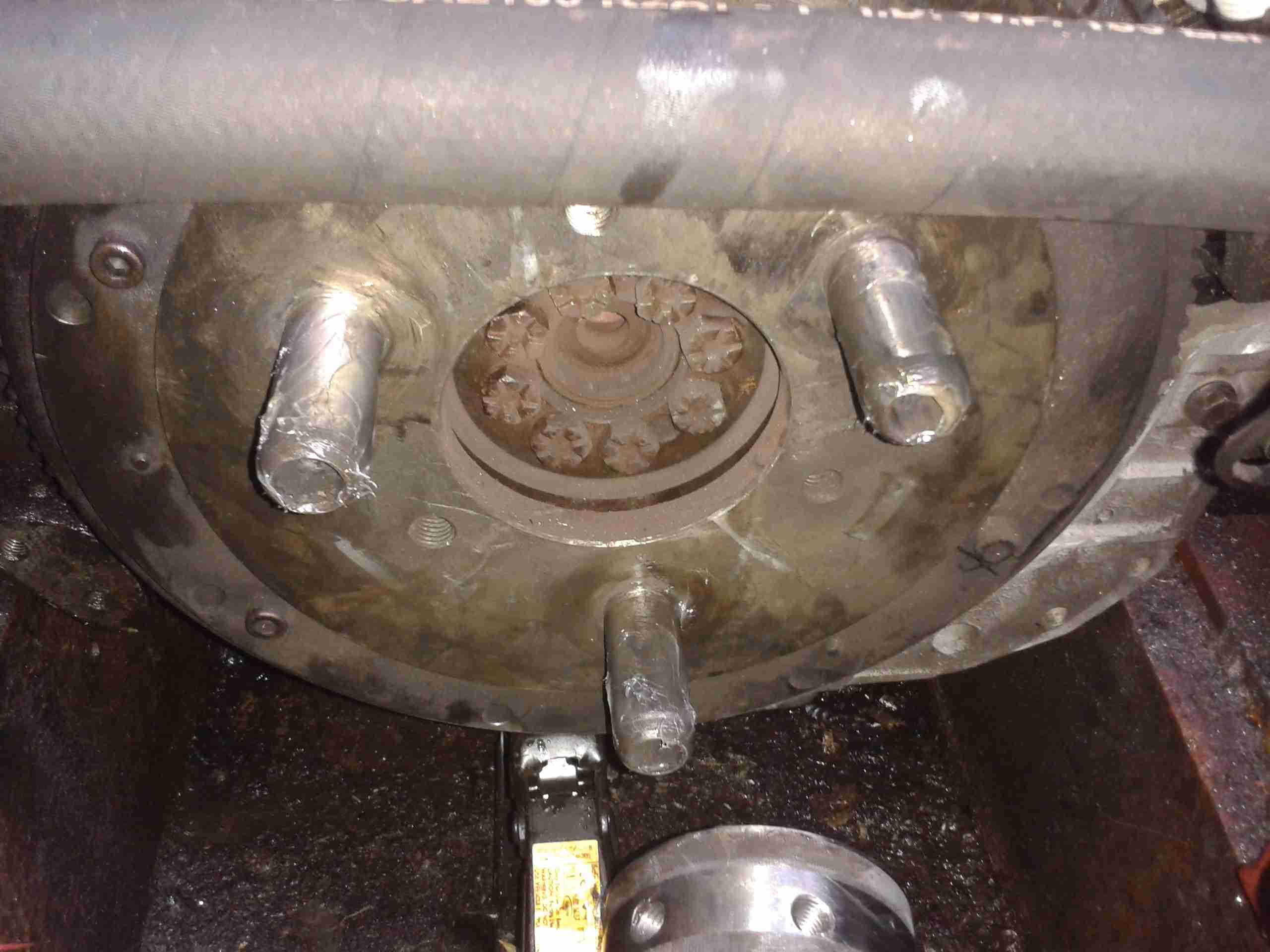
Flywheel
Here’s the engine flywheel, where the rubber coupling normally sits. The mounting pins have been greased ready to accept the rest of the coupling.
Doughnut
Here’s the rubber element mounted on the pins – there’s nothing holding it there in normal operation apart from the mating side of the coupling with the pump.
Unfortunately the weather here in Manchester has prevented us from getting any further – more t0 come when the rain stops!
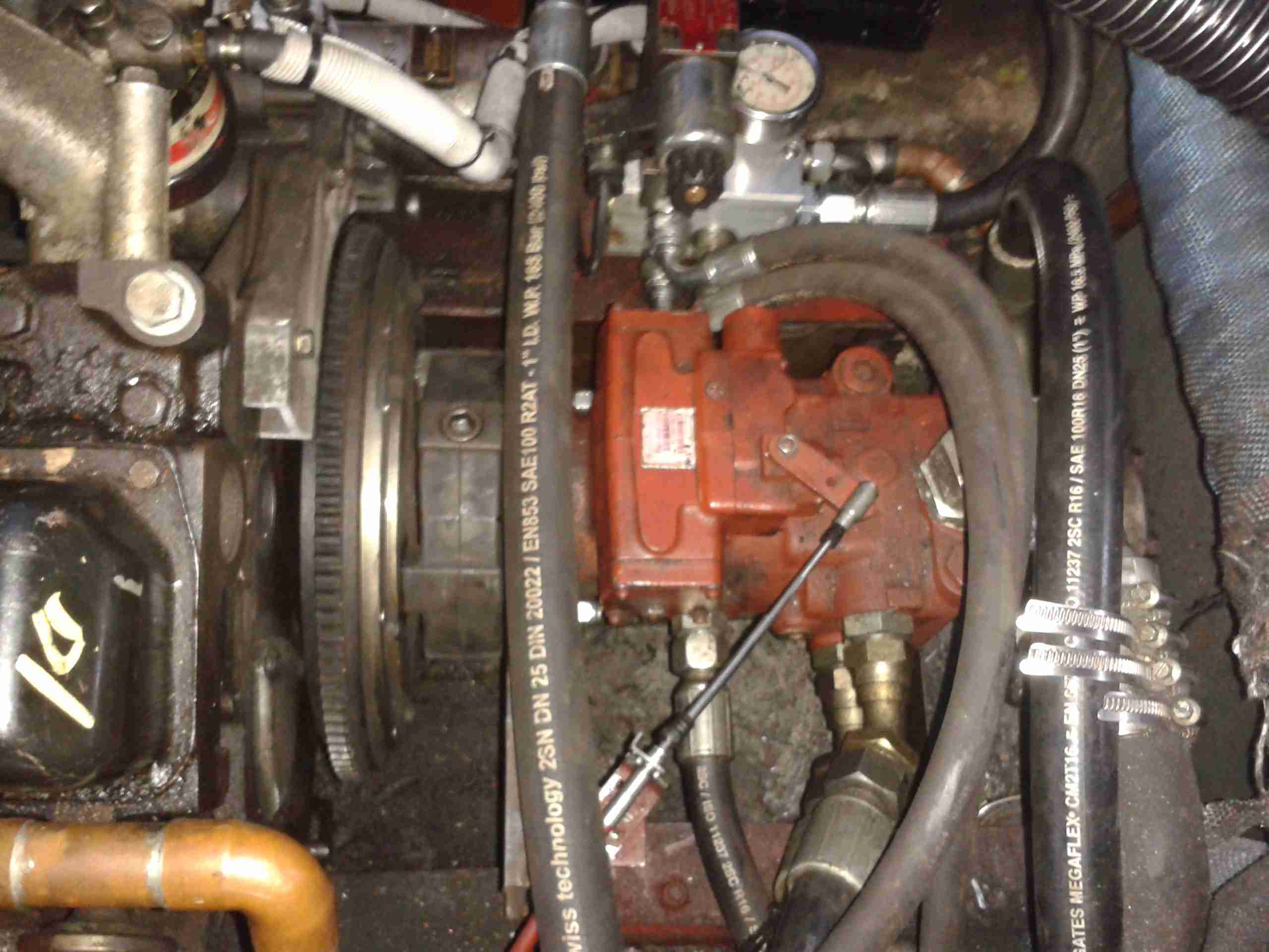
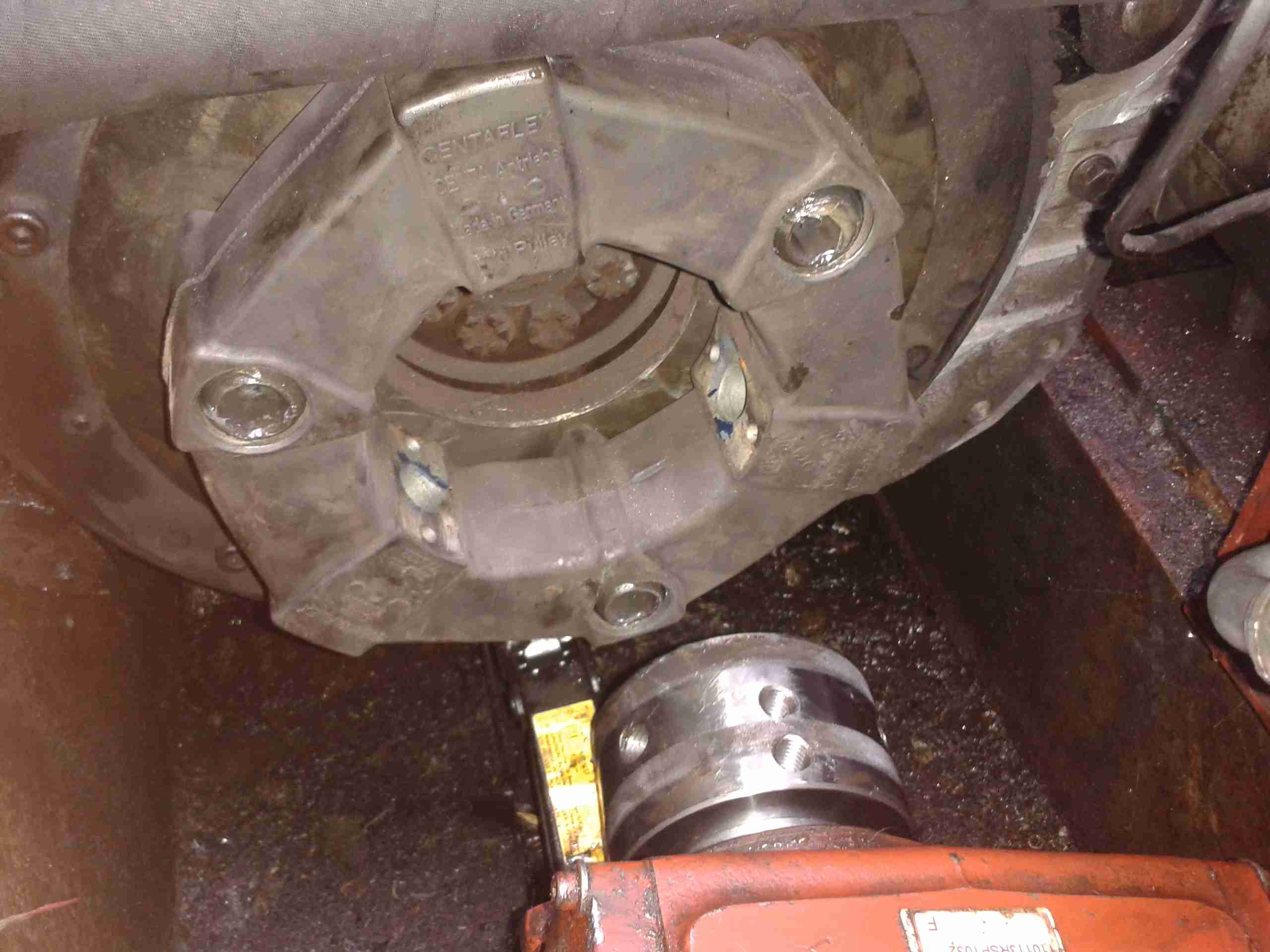
As I have posted about before, the main propulsion system onboard the boat is all hydraulic. To get the drive from the flywheel of the engine to the hydraulic pump stack, a custom drive plate was machined by Centa Transmissions over in Yorkshire, and a Centaflex A coupling was fitted to this.
Centaflex A Coupling
This coupling is a big rubber doughnut, bolted to a centre hub of steel. The steel hub is splined onto the input shaft of the hydraulic pump stack.
Pump Stack
The problem we’ve had is that to prevent the coupling from riding along the splines in operation, a pair of giant grub screws are provided in the side of the centre steel boss, that compress the splines to lock the device in place. These screws are a nightmare to get tightened down (the engineer from Centa who originally came to survey the system said we’d probably shear some tools off trying).
Because of this, the grub screws have loosened over the last 350-odd hours of running & this has had the effect of totally destroying the splines in the hub.
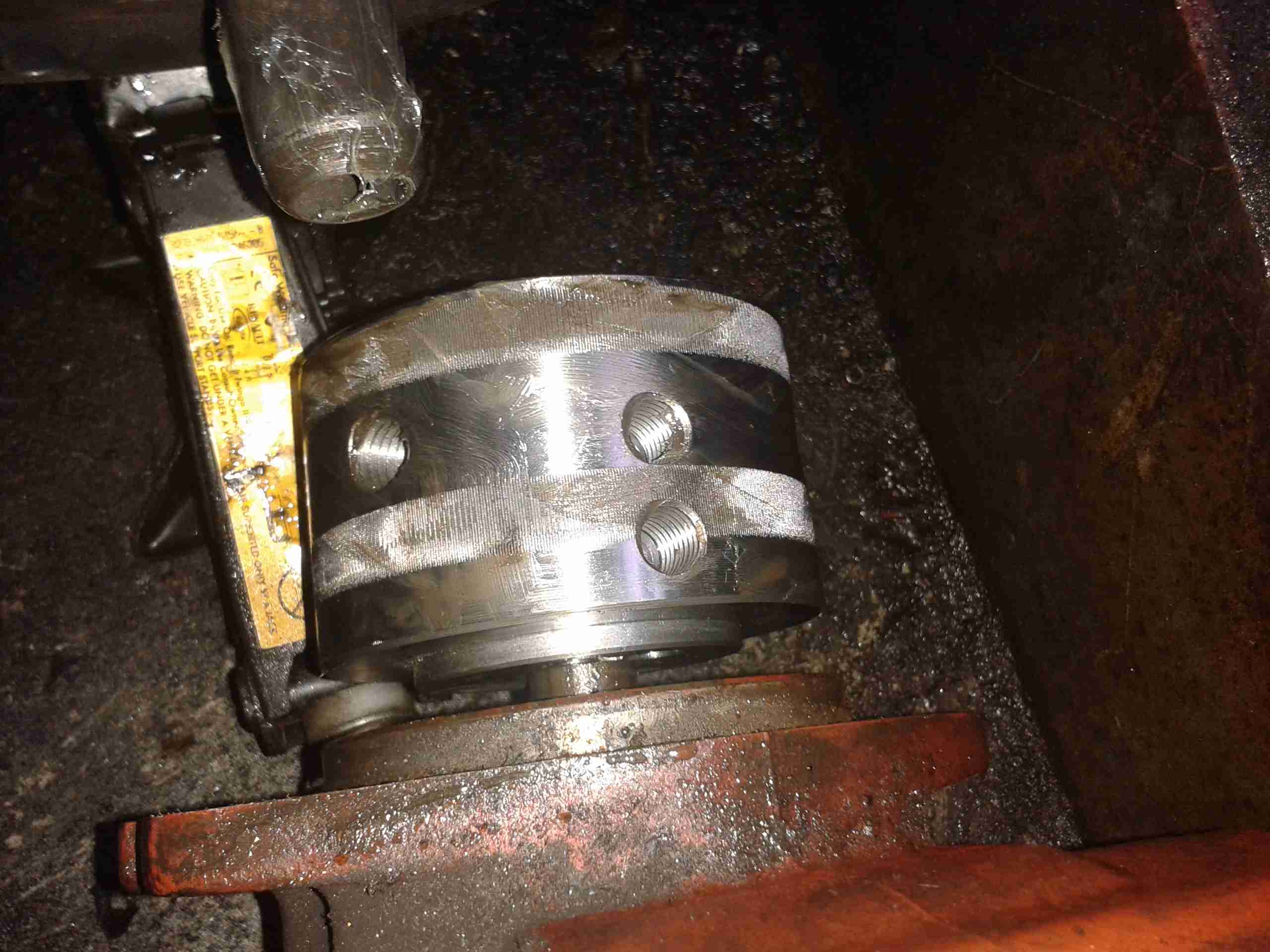
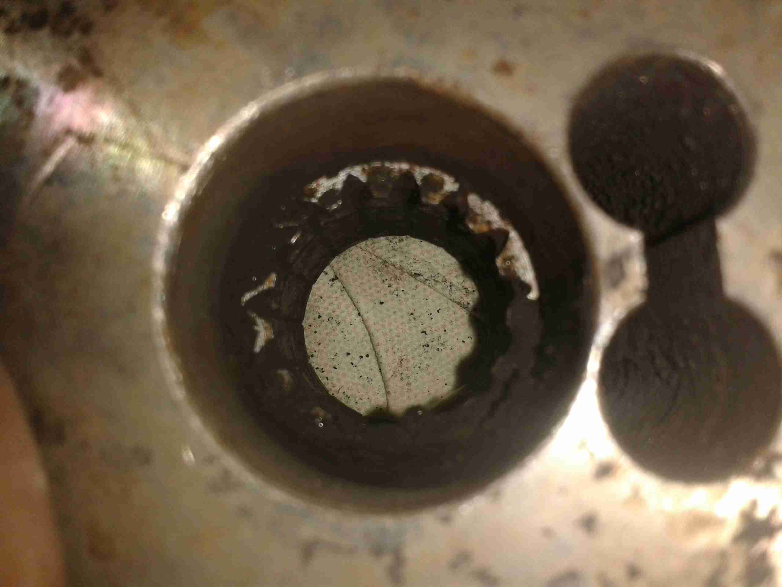
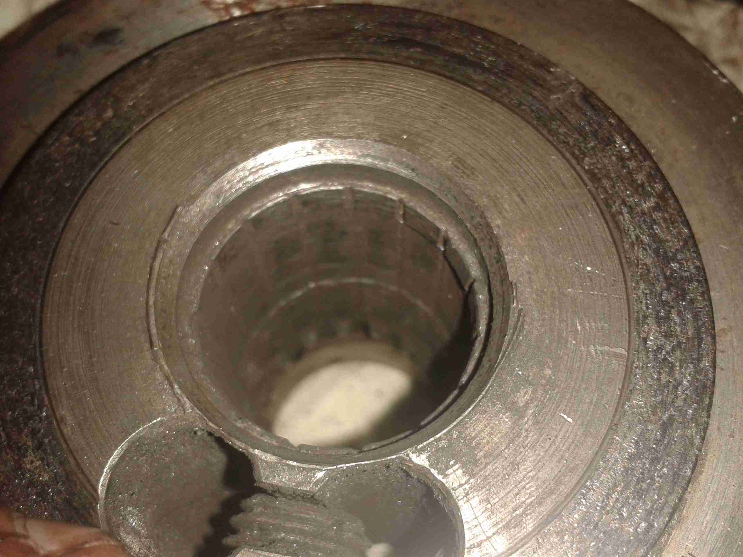
Spline Remains
Here’s the backside of the centre boss, with what remains of the splines, the figure-8 shaped gap on the right is where the securing grub screws deform the steel to lock the coupling into place.
No More Splines
Here’s the other side of the coupling, showing the damage. The splines have effectively been totally removed, as if I’d gone in there with a boring bar on the lathe. Luckily this part isn’t too expensive to replace, and no damage was done to the input shaft of the hydraulic pump stack (Mega ££££). Quite luckily, this damage got to the point of failure while running the engine on the mooring, so it didn’t leave us stranded somewhere without motive power.
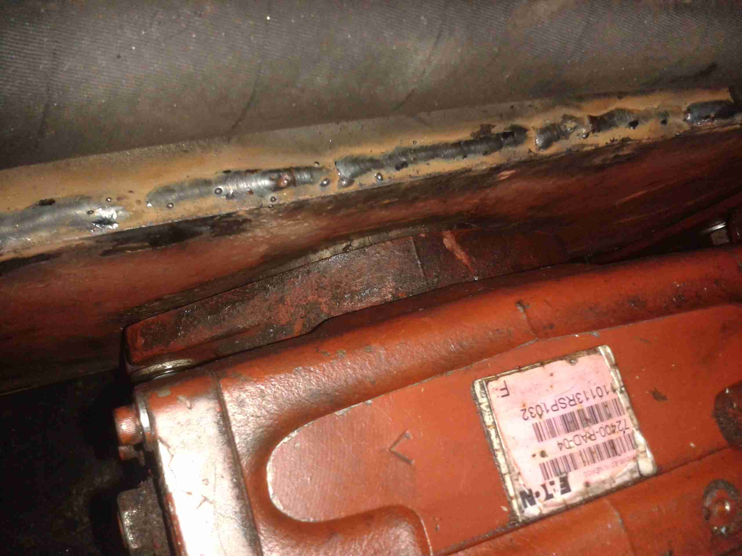
The boat being over 50 years old, there are some parts that are suffering from rather bad corrosion. The bow deck plate is about the worst, so this is being replaced in it’s entirety.
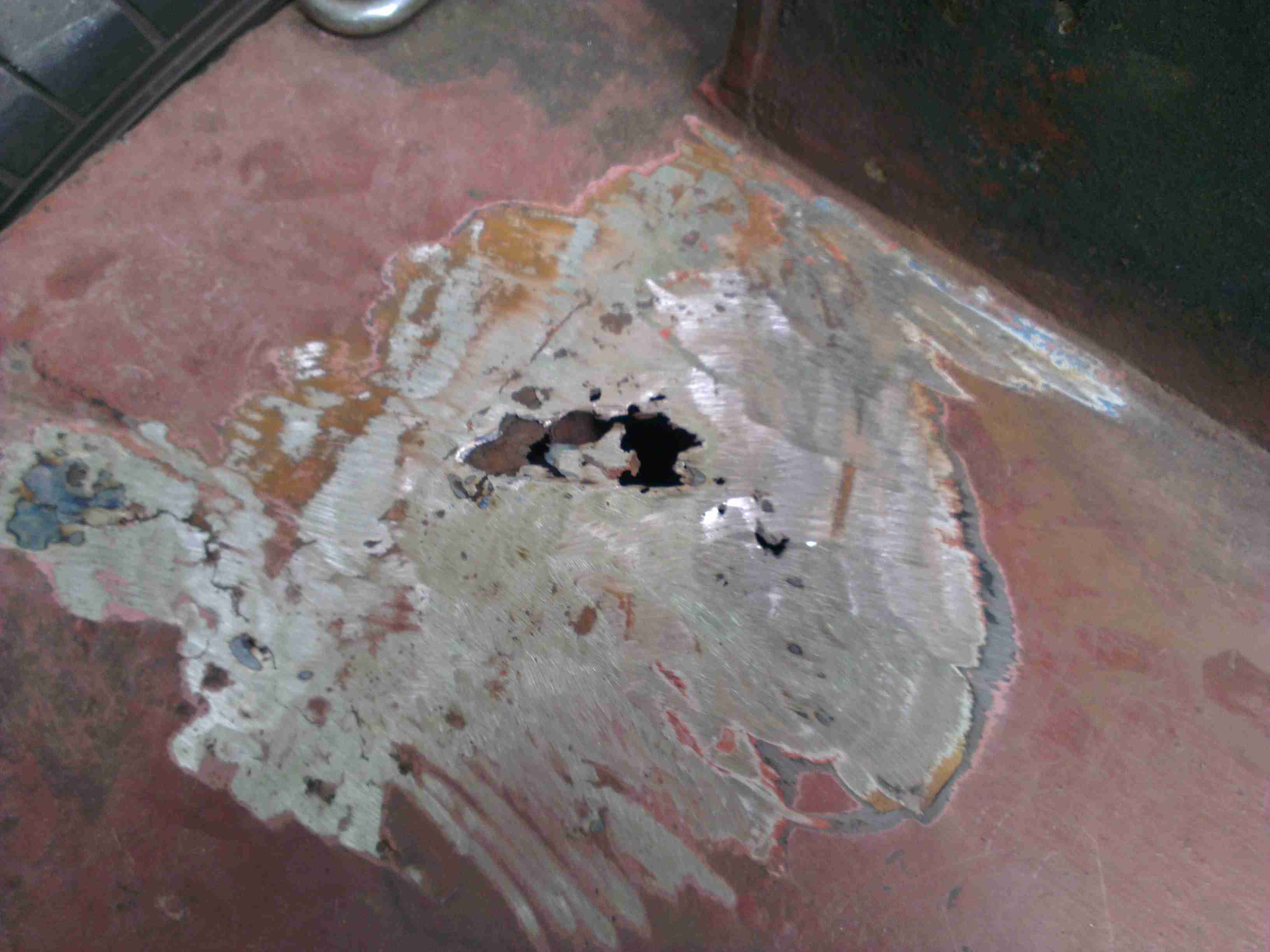
However a hole has developed in the stern deck, this has rusted from the inside out due to condensation in the engine bay.
After Grinding
After taking a grinder to the area, this is how it looks. The steel has gone from 1/4″ to paper thin, not surprising after 50 years or so!
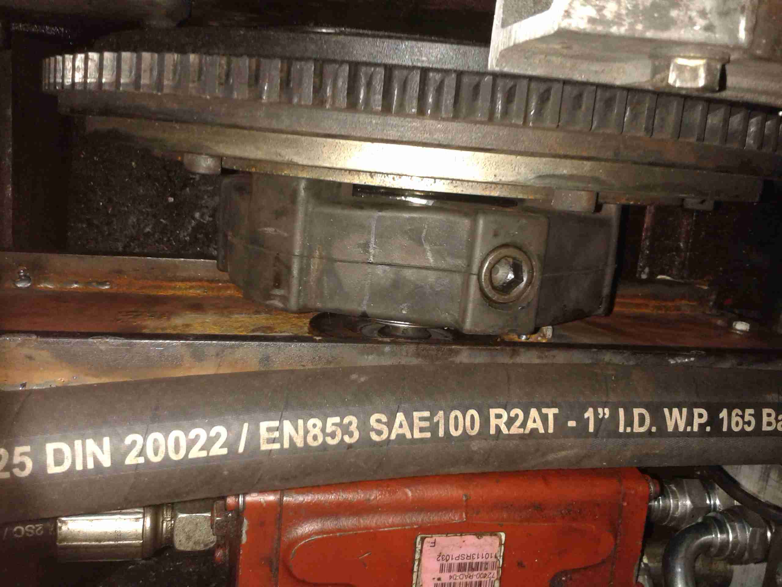
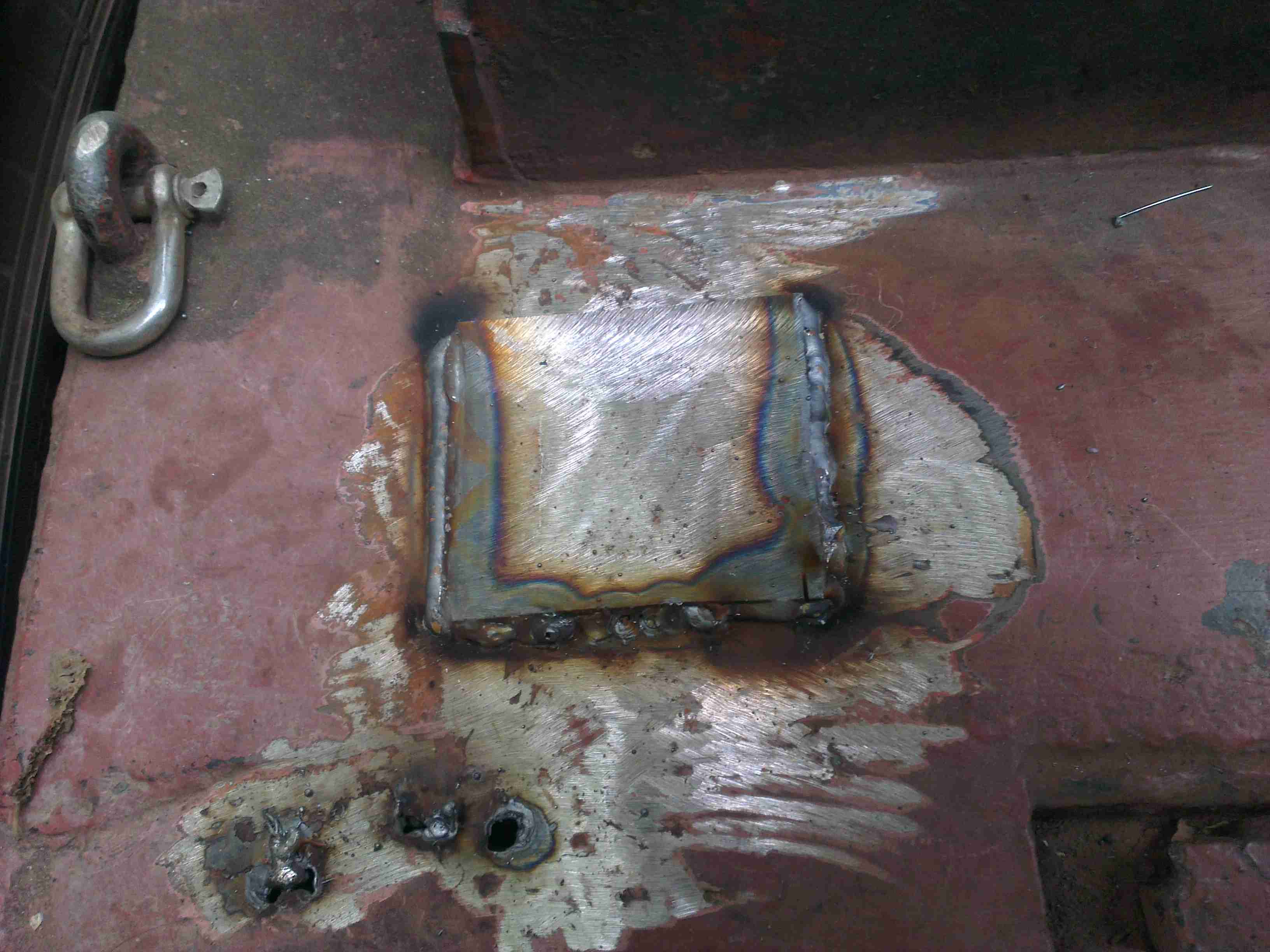
It would be a massive job to cut out the entire plate for replacement, so a patch was made from 5mm steel, and welded over the hole:
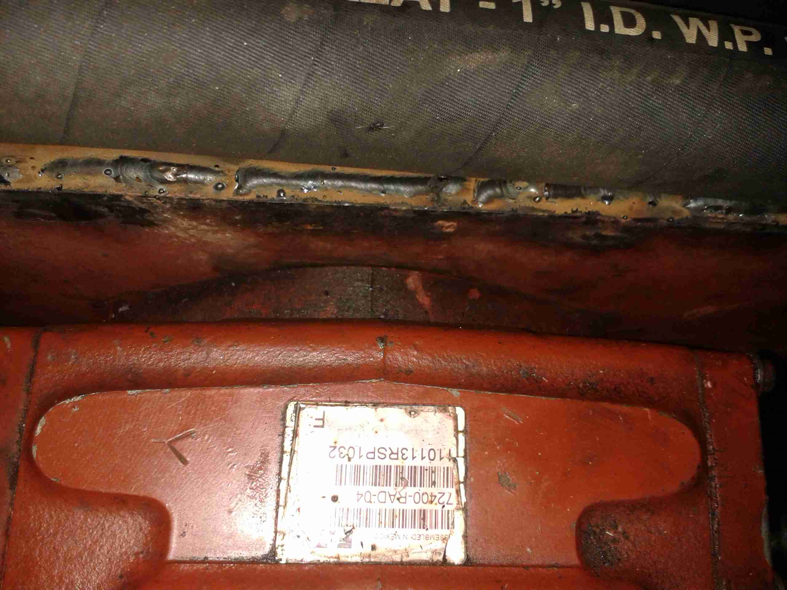
Patch
Here’s the patch partially welded. The holes closer to the bottom are another small area of damage, and another patch will have to be cut for this. It’s covering the deck drain channel so it’s frequently under water, so it’s inevitable that this section would corrode.
All that is left to do now is to finish off the welding, grind everything smooth & repaint.
To provide more run time with the conversion to petrol & spark ignition, I have also upgraded the on-board electronics supply to compensate for the extra ~650mA draw of the ignition module.
This modification is centred around a 3S Lithium-Polymer battery pack, providing a nominal 11.1v to a voltage regulator, which steps down this higher voltage to the ~6v required by the receiver & servo electronics.
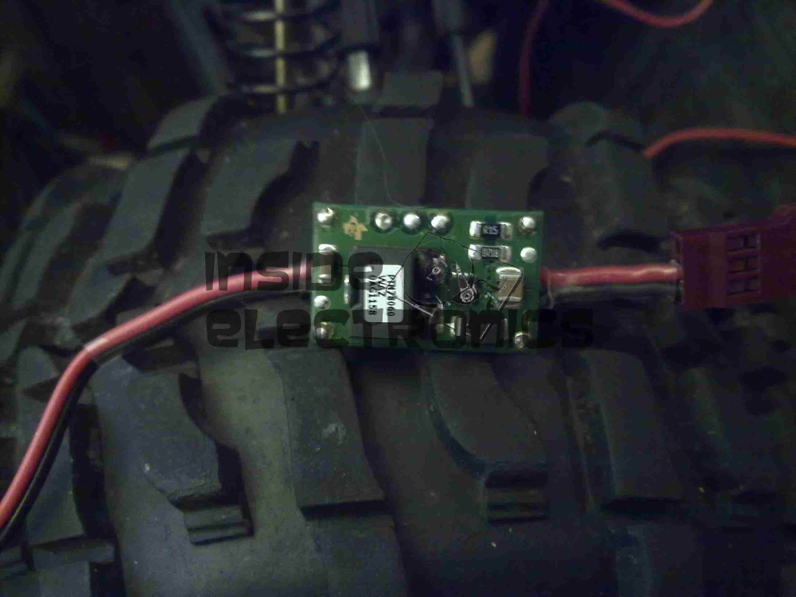
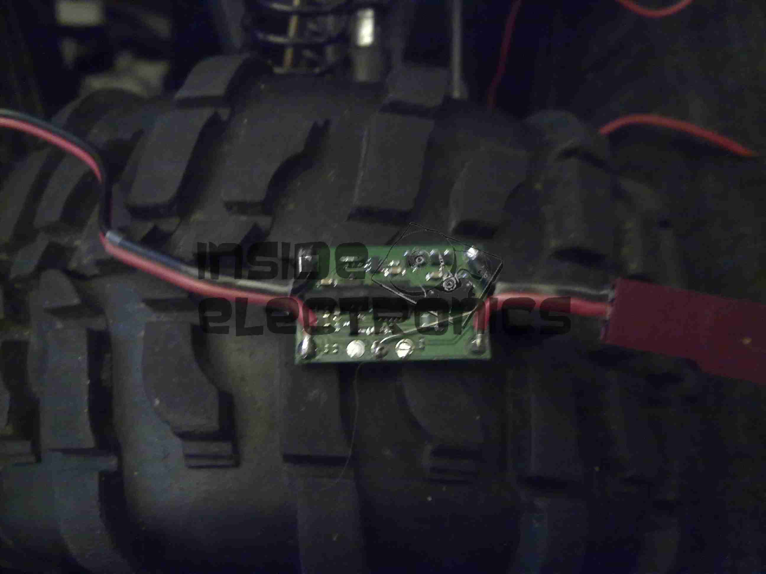
Power RegulatorPower Regulator
The regulator, shown above, is a Texas Instruments PTN78060WAZ wide-input voltage adjustable regulator. This module has an exceptionally high efficiency of ~96% at it’s full output current of 3A. The output voltage is set by a precision resistor, soldered to the back of the module, in this case 6.5v. Standard RC connectors are used on the regulator to allow connection between the power switch & the radio receiver.
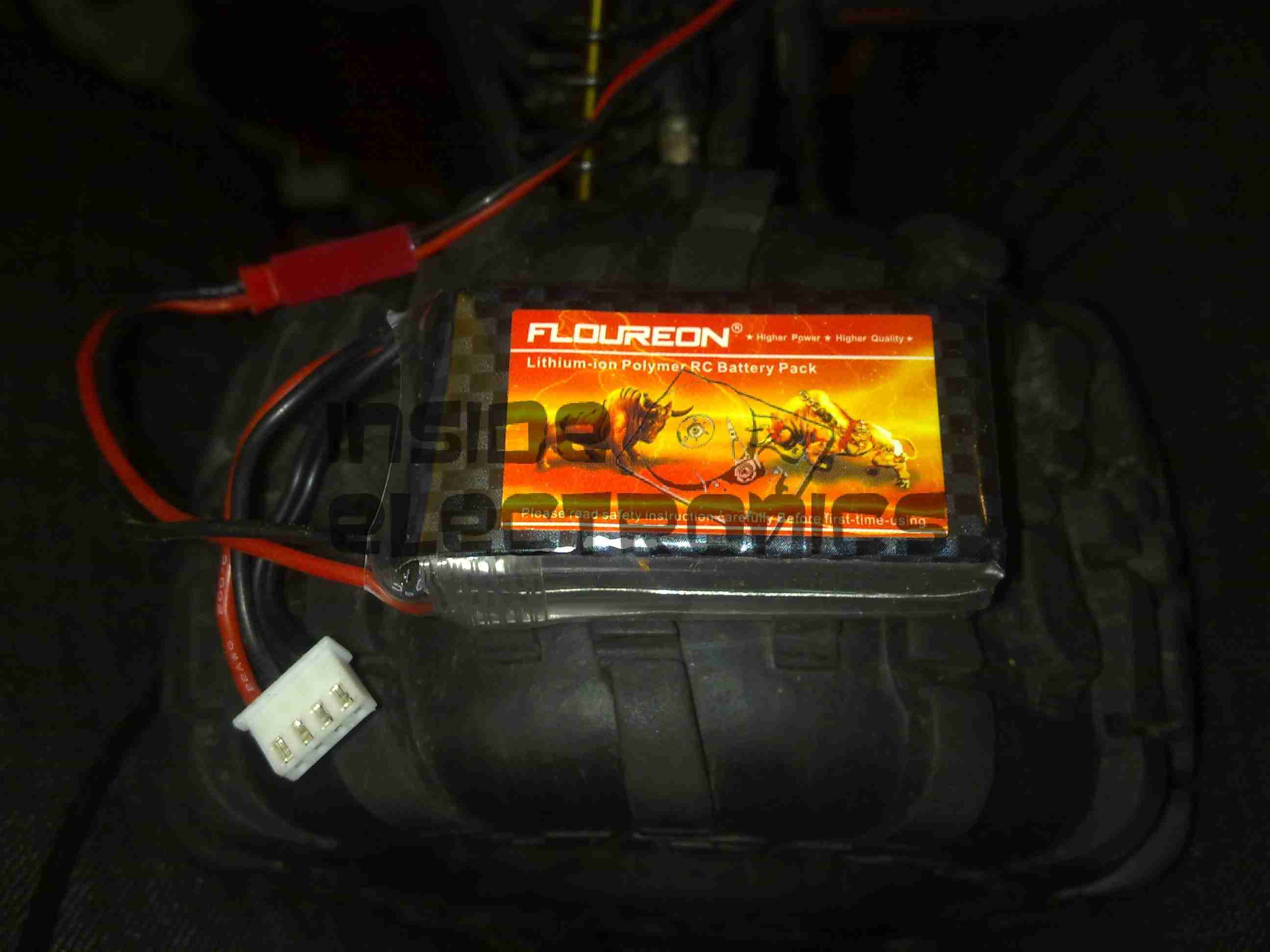
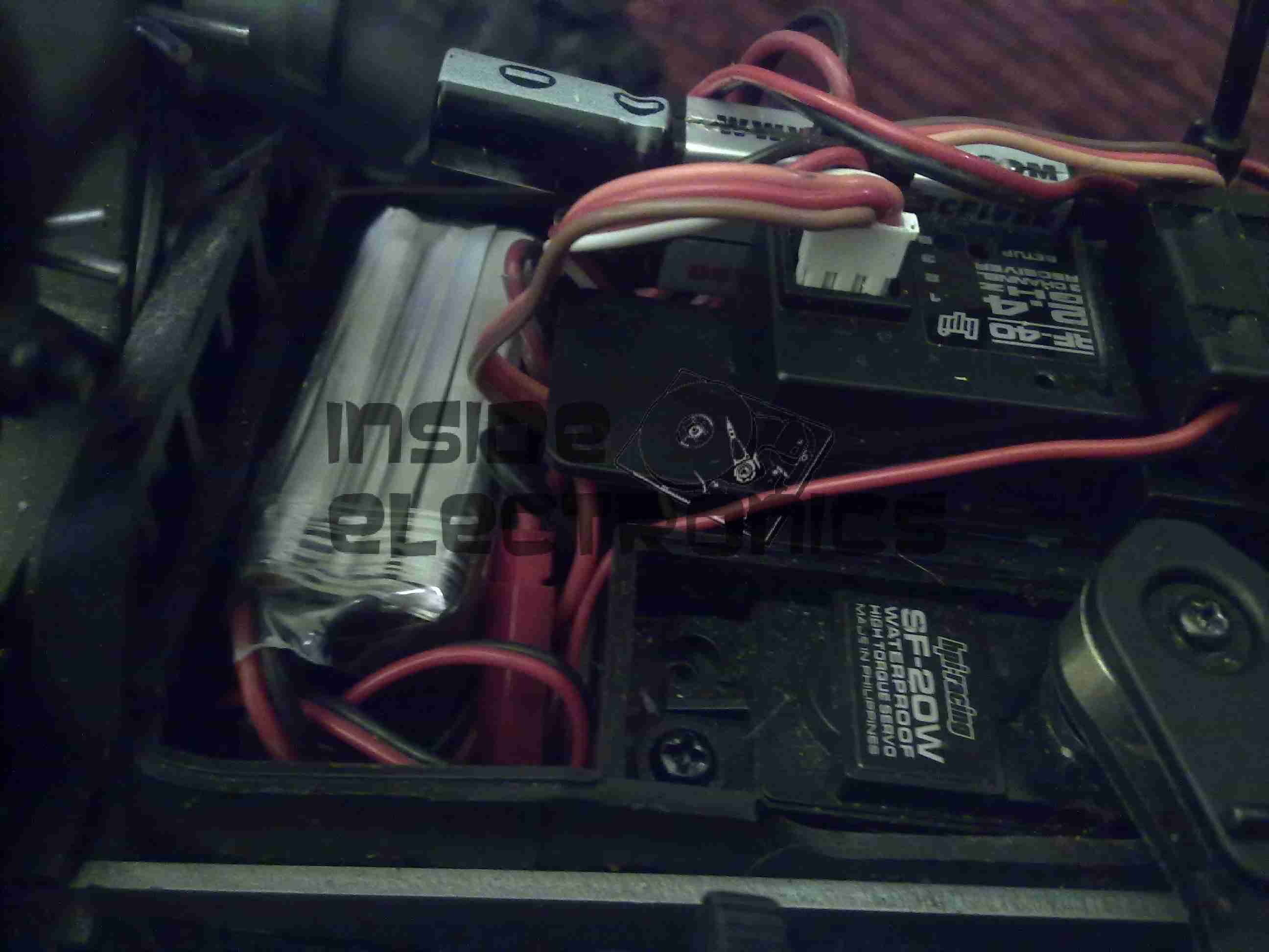
Receiver Box
Everything tucked away into place inside the receiver box. The 3S 1000mAh LiPo fits perfectly in the space where the original Ni-Mh hump pack was located.
The completely stable output voltage of the regulator over the discharge curve of the new battery gives a much more stable supply to the radio & ignition, so I should experience fewer dropouts. Plus the fact that the engine now relies on power from the receiver pack to run, it’s a built in fail safe – if the power dies to the receiver, the engine also cuts out.
While I was already well aware of the effects of petrol on silicone products – the stuff swells up & dissolves over a very short period of time, which makes it an unsuitable material for seals in a petrol fuel system.
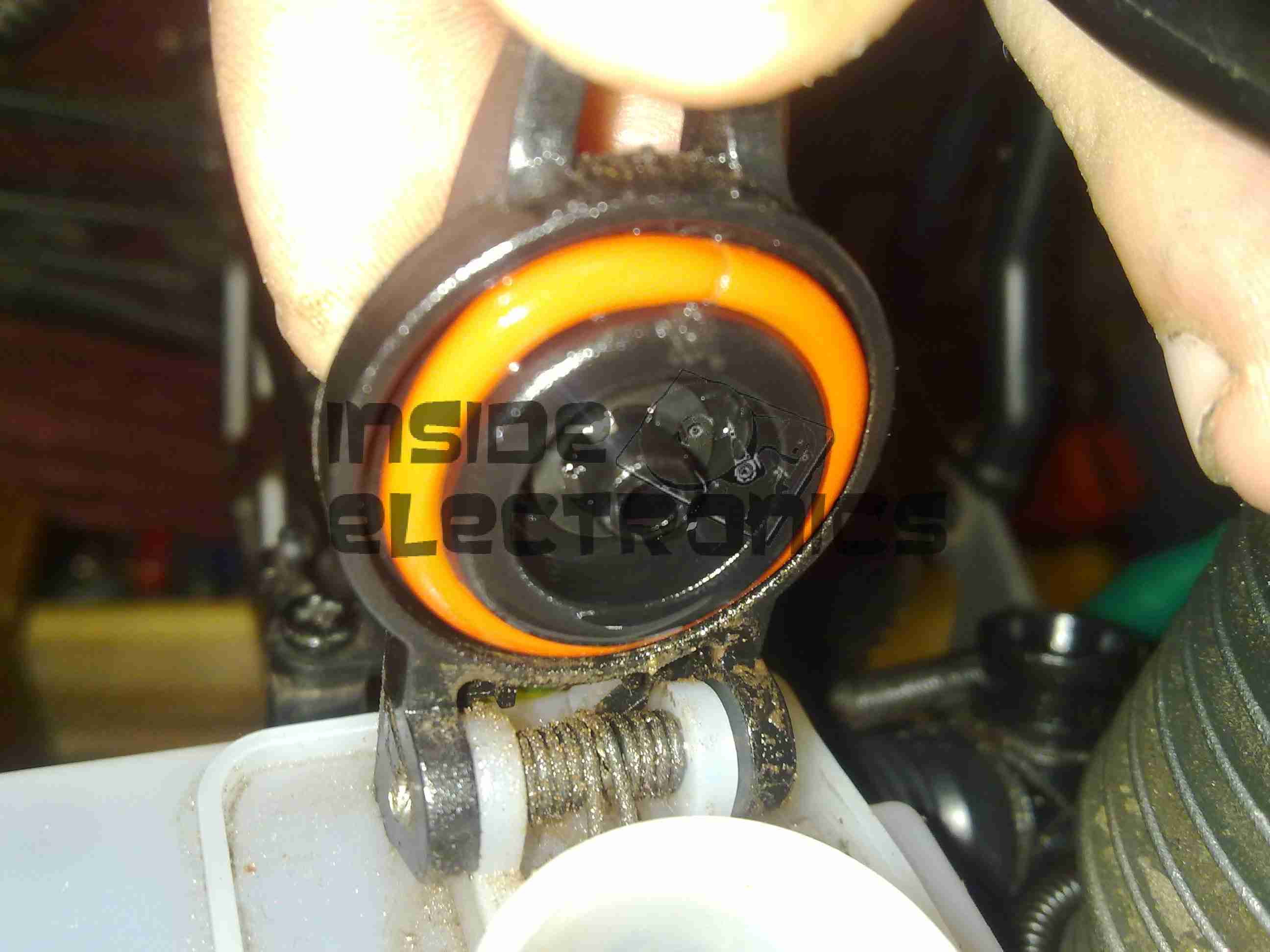
Fuel Tank Cap Seal
I wasn’t aware the O-Ring on the fuel tank cap of the Savage is silicone, as can be seen in the image above it has swelled up to much larger than it’s original size. It’s supposed to sit in the groove on the cap & fit into the filler neck when closed.
This was only from a couple of hours of petrol exposure, now the seal is such an ill fit that the cap will not close properly.
The solution here is to replace the ring with a Viton O-Ring, 2.5mm cross section, 23mm ID. I assume the fuel tank is made of polypropylene – this should stand up fine to the new fuel.
Another concern was the O-Rings on the carburettor needles, however these seem to be made of a petrol-resistant material already & are showing no signs of deterioration after 24+ hours of fuel immersion.
The O-Rings that seal the engine backplate to the crankcase also seem to be working fine with the new fuel.
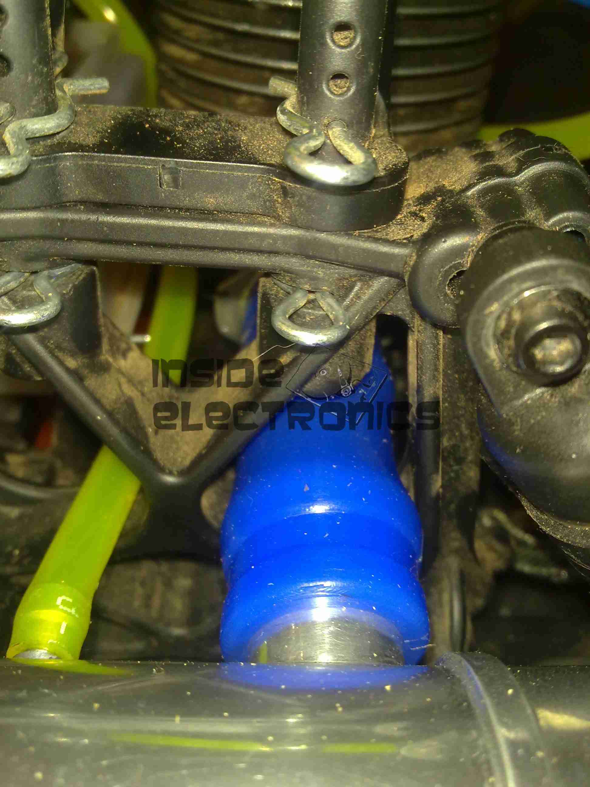
Another silicone part on the engine is the exhaust coupling, between the back of the cylinder & the silencer, I’m not aware of a suitable replacement as yet, although as it will mainly be exposed to the combustion products & not raw fuel, it may just survive the task.
Exhaust Coupling
The extra heat from burning petrol in one of these engines may also put a lot of stress on this component, if it eventually fails I may attempt a replacement with automotive hose – time will tell on this one.
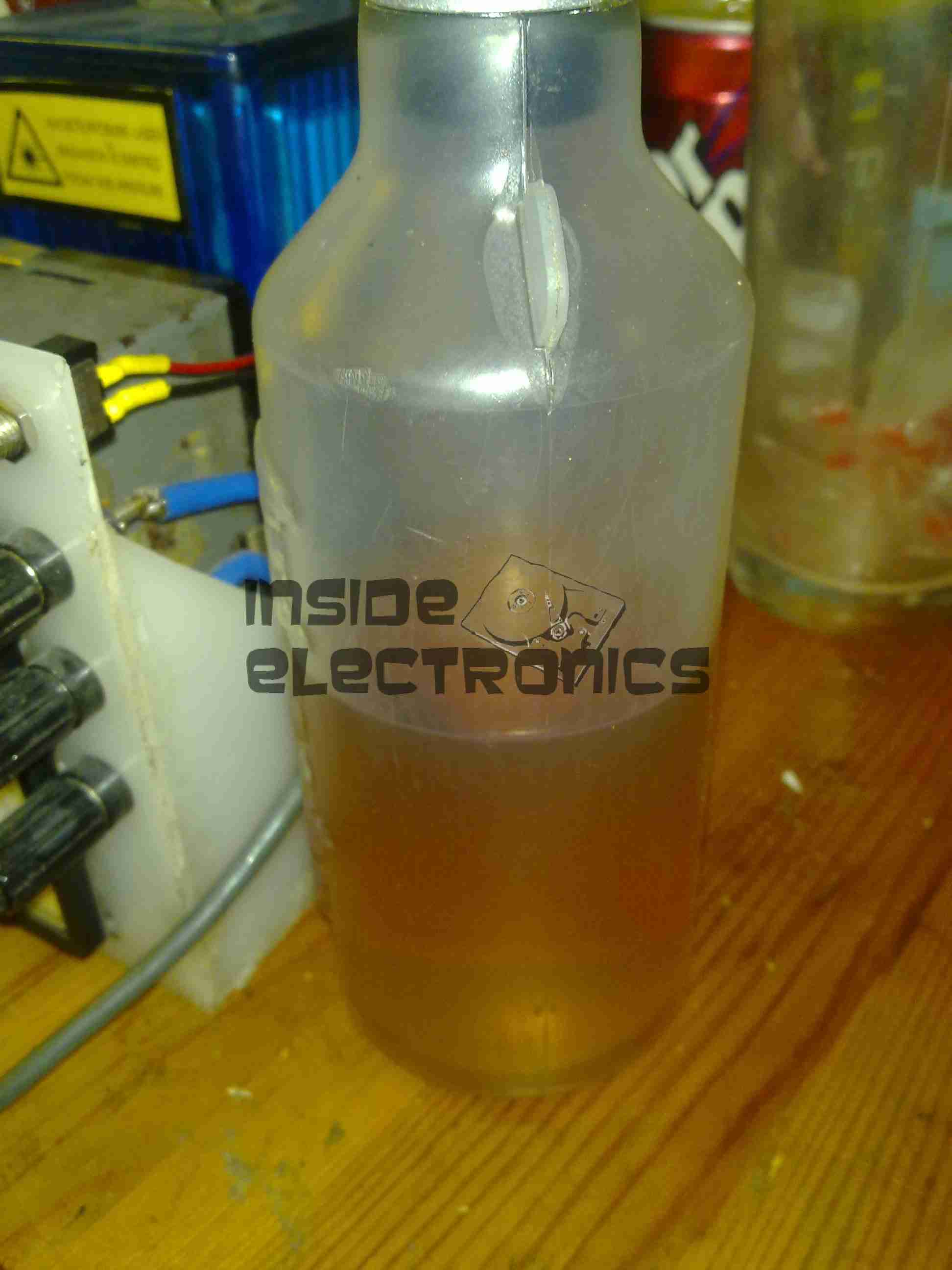
Fuel Bottle
I’m also not sure of the plastic that standard fuel bottles are made from – their resin identification number is 7, so it could be any special plastic, but I’m guessing it’s Nylon.
However according to the spec sheet for Nylon, it’s chemically compatible with petrol – yet the plastic appears to be getting softer with exposure, so it may be a special blend designed specifically for glow fuel.
Besides these small glitches, the engine is running well on it’s newly assigned diet of petrol, I’m currently running an 18:1 mix of petrol to oil (250ml oil to 4.5L of petrol), this seems to be providing more than adequate lubrication. While it smokes like a chimney, plenty of unburned oil is making it out of the exhaust, so the engine’s internals should have a liberal coating.
I’m yet to actually run the model out in open space so I can start tuning the mixture, but bench tests are promising.
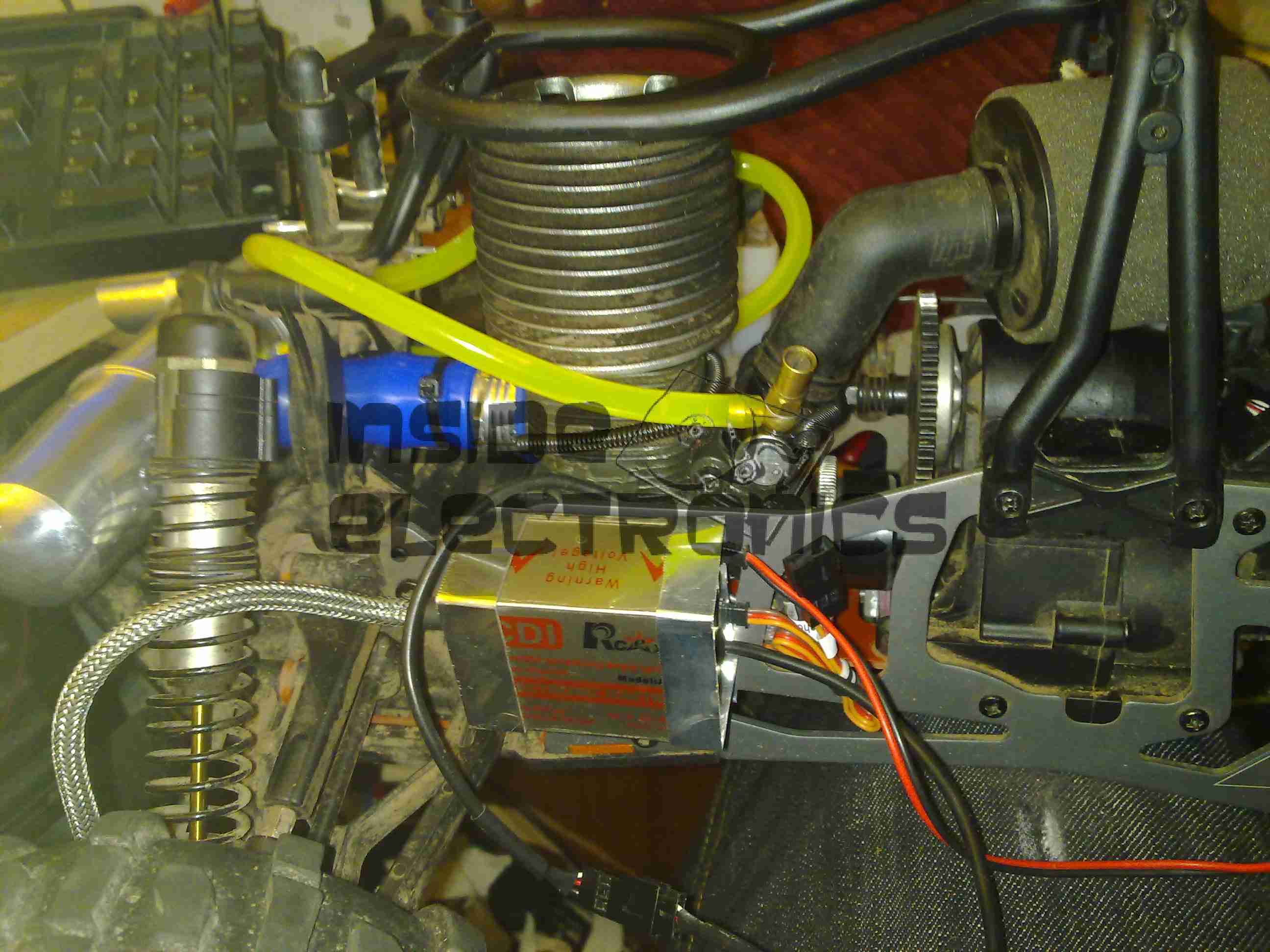
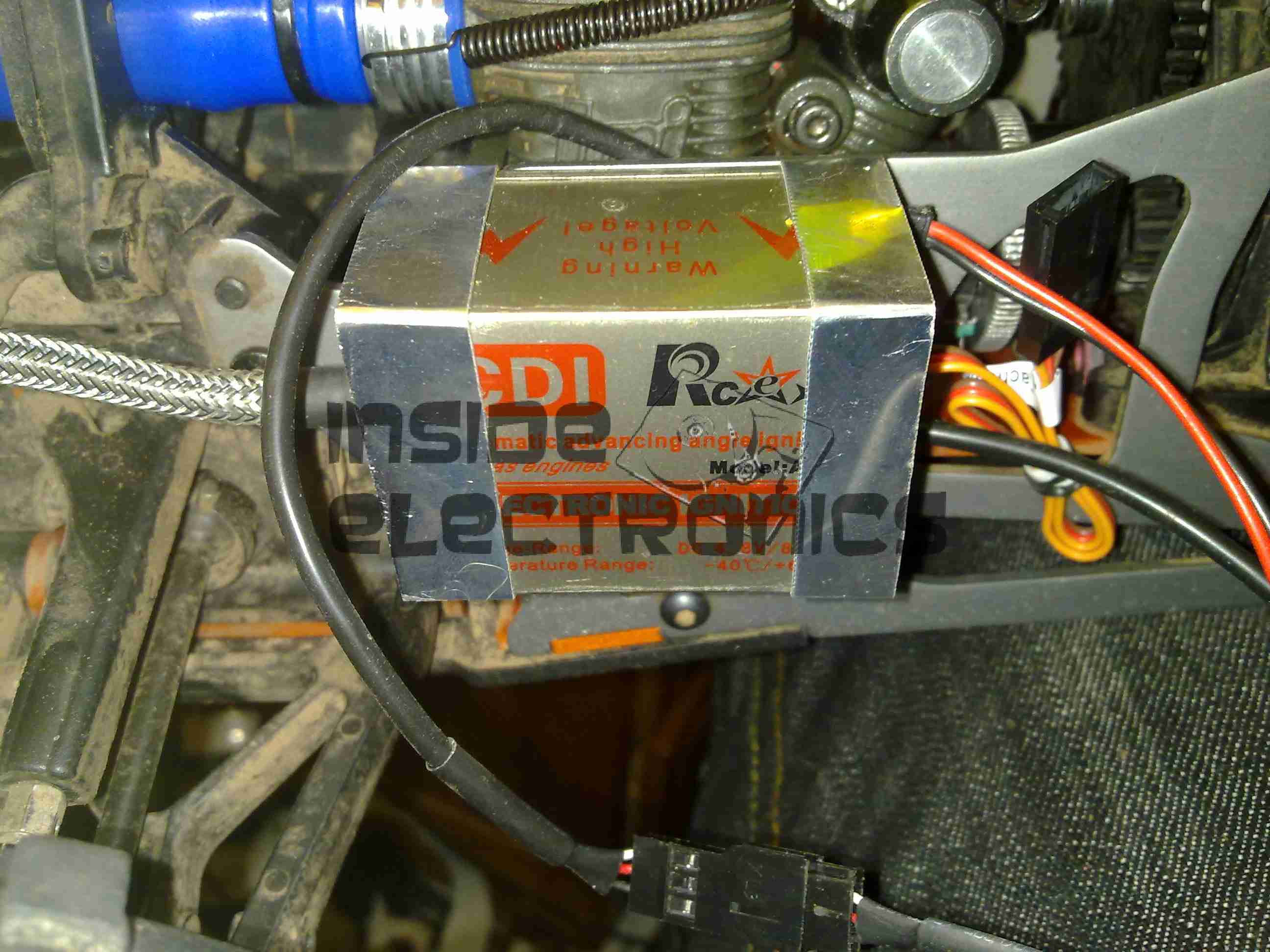
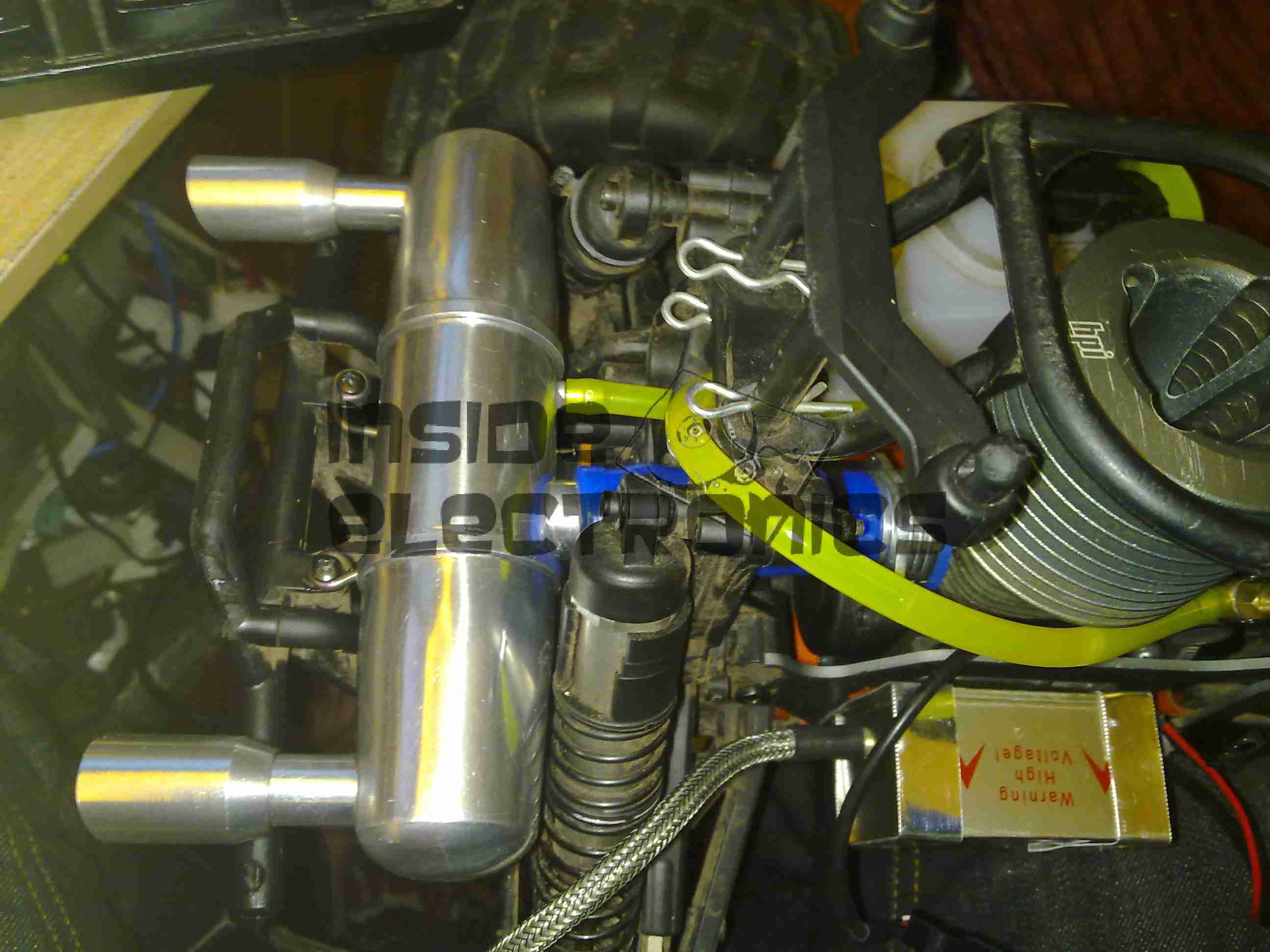
The engine now with it’s required ignition sensor, it is now mounted back on the chassis of the model. I have replaced the stock side exhaust with a rear silencer, so I could fit the ignition module in place next to the engine.
For the mounting, I fabricated a pair of brackets from 0.5mm aluminium, bent around the module & secured with the screws that attach the engine bed plate to the TVPs. The ignition HT lead can be routed up in front of the rear shock tower to clear all moving suspension parts, with the LT wiring tucked into the frame under the engine.
In this location the module is within the profile of the model chassis so it shouldn’t get hit by anything in service.
Rear Exhaust
New exhaust silencer fitted to the back of the model. This saves much space on the side of the model & allows the oily exhaust to be discharged away from the back wheel – no more mess to wipe up.
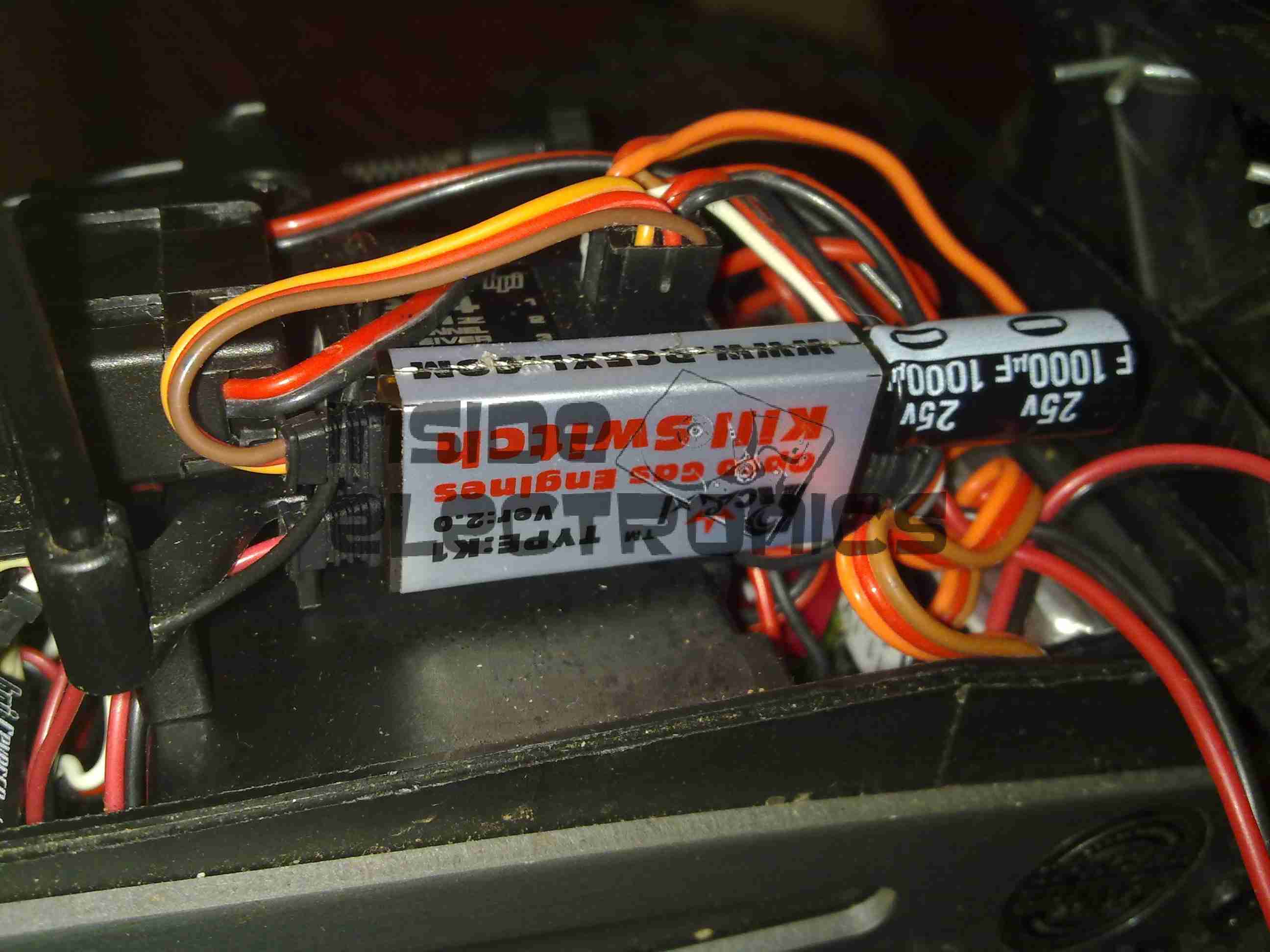
Kill Switch
The ignition switch fitted into the receiver box. This is wired into channel 3 of the TF-40 radio, allowing me to remotely kill the engine in case of emergency. I have fitted a 25v 1000µF capacitor to smooth out any power fluctuations from the ignition module.
The radio is running from a 11.1v 1Ah 3S LiPo pack connected to a voltage regulator to give a constant 6.5v for the electronics. I found this is much more reliable than the standard 5-cell Ni-MH hump packs.
Fuel Tank
The stock silicone fuel tubing has been replaced with Tygon tubing to withstand the conversion to petrol.
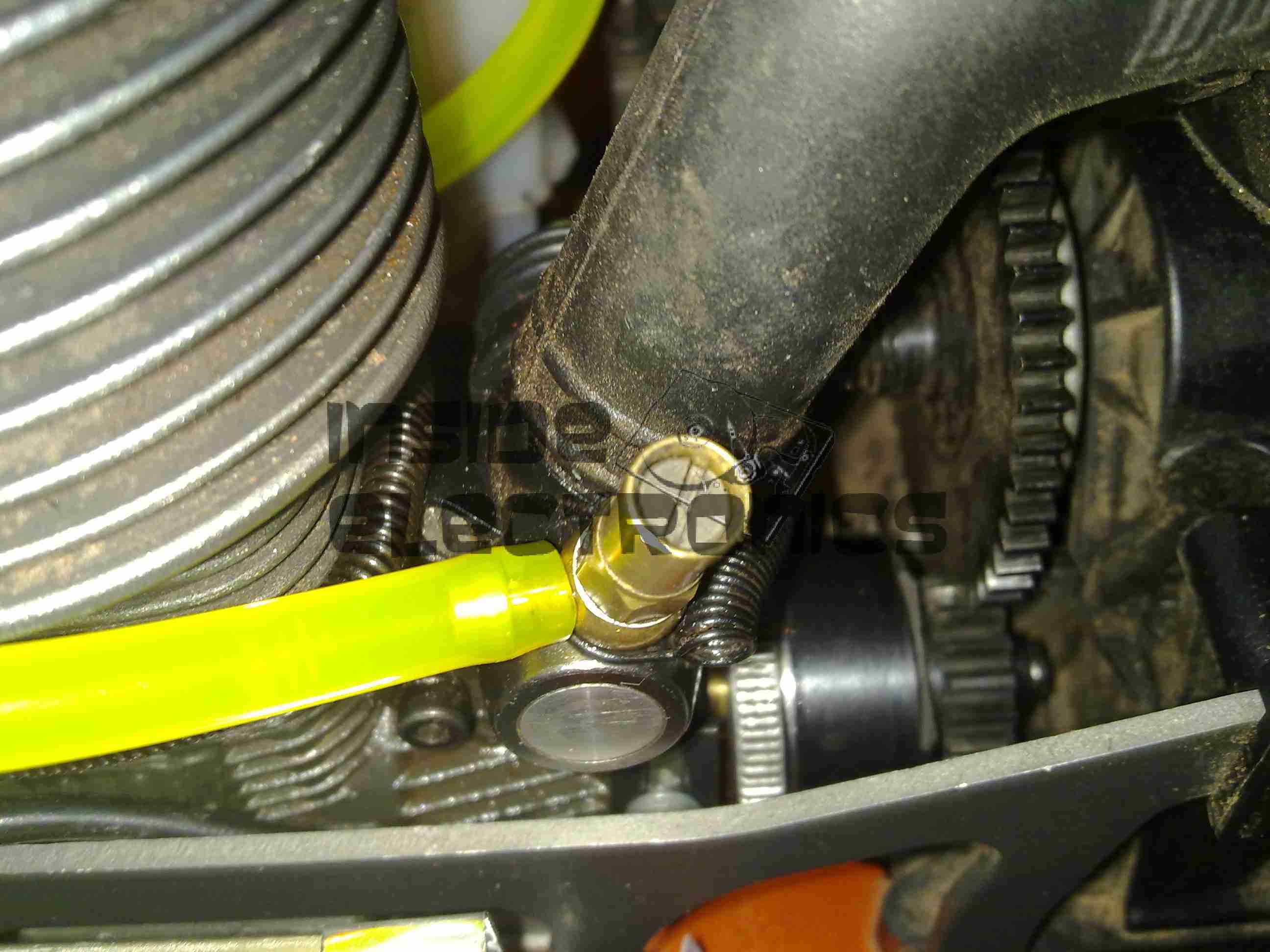
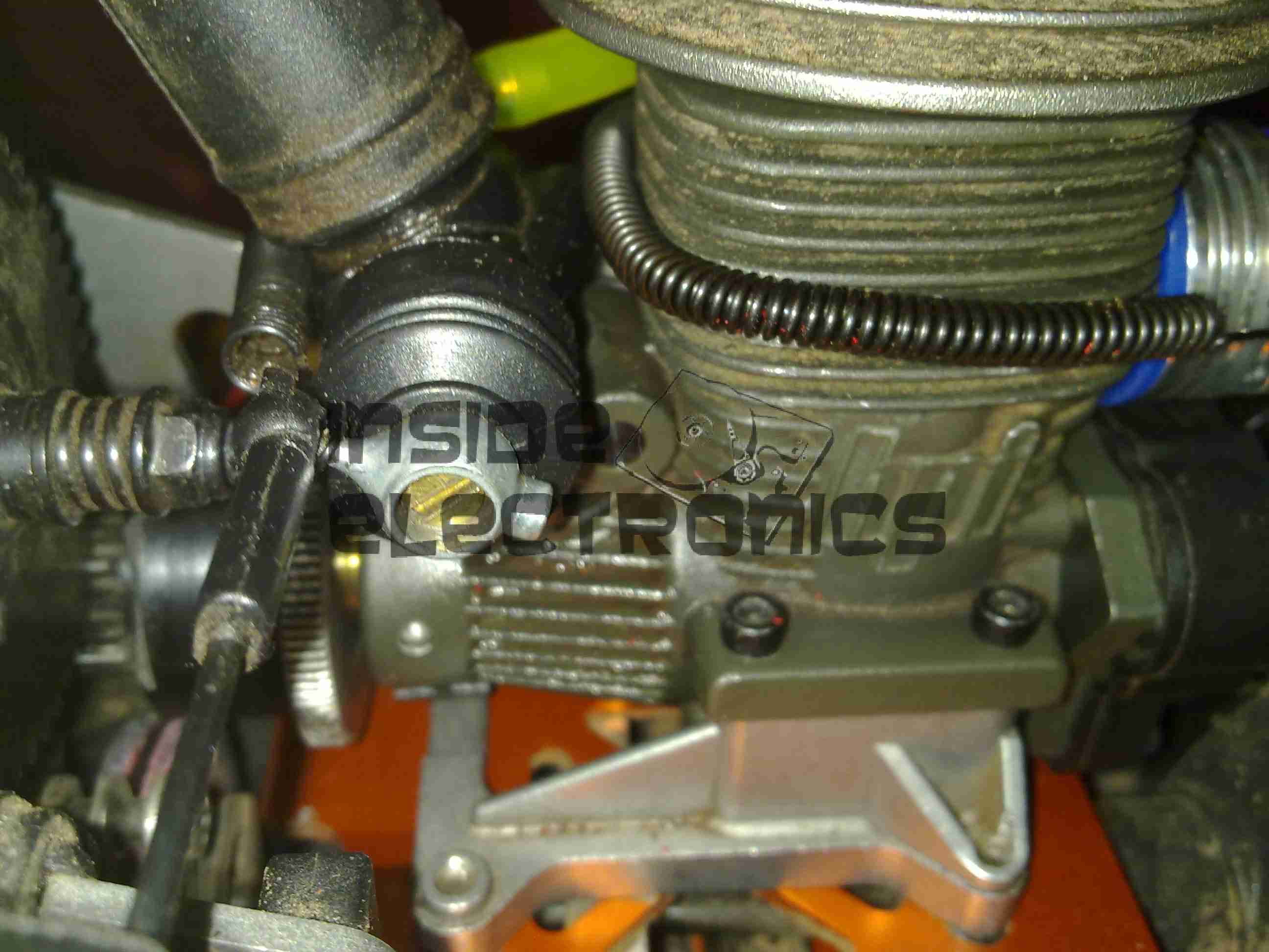
High Speed Needle
High speed needle tweaked to provide a basic running setting on petrol. This is set to ~1.5mm below flush with the needle housing.
Low Speed Needle
Low speed needle tweaked to provide a basic running setting on petrol. This is set to ~1.73mm from flush with the needle housing.
As petrol is a much higher energy density fuel, it requires much more air than the methanol glow fuel – ergo much leaner settings.
The settings listed should allow an engine to run – if nowhere near perfectly as they are still rather rich. It’s a good starting point for eventual tuning.
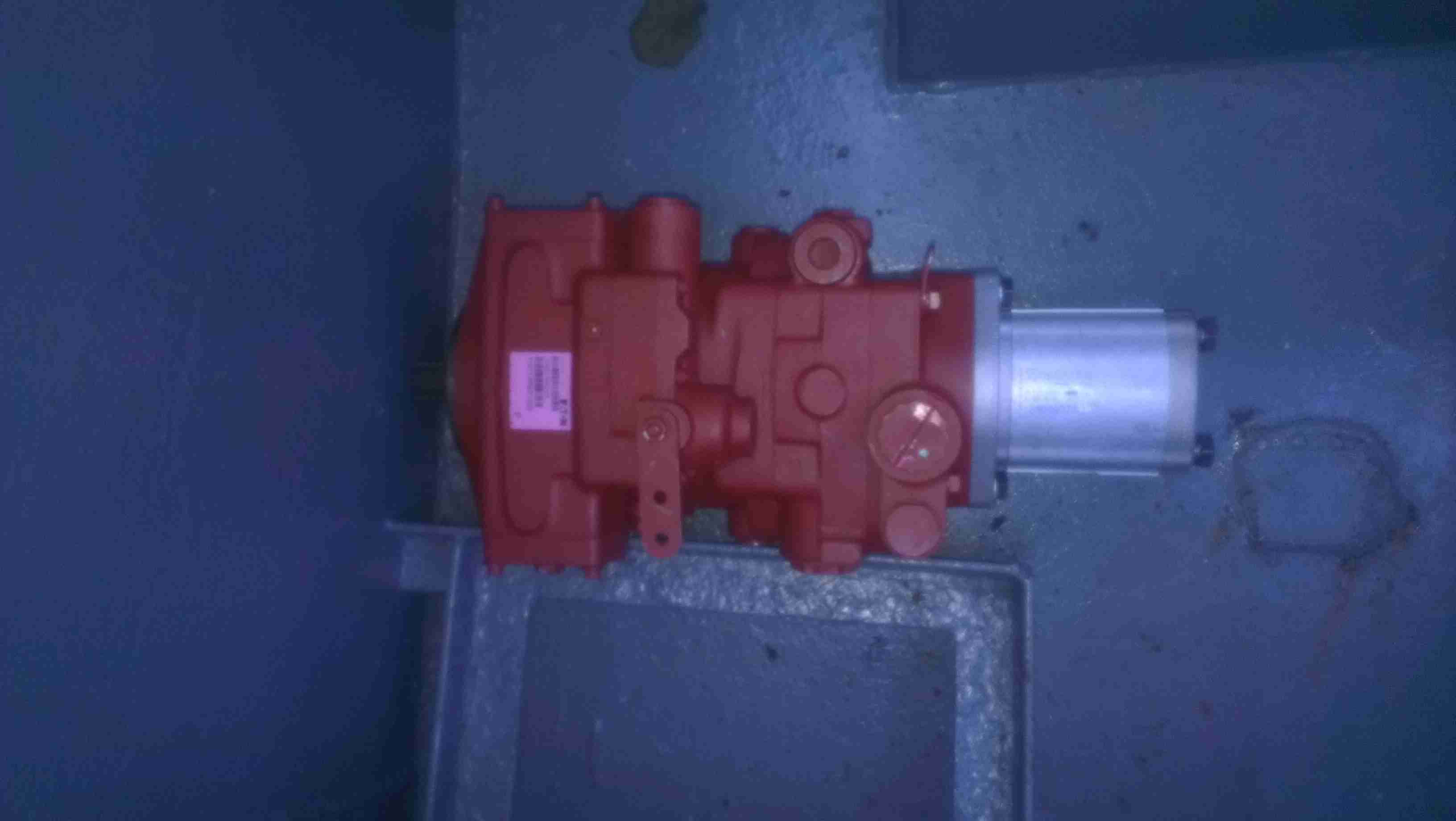
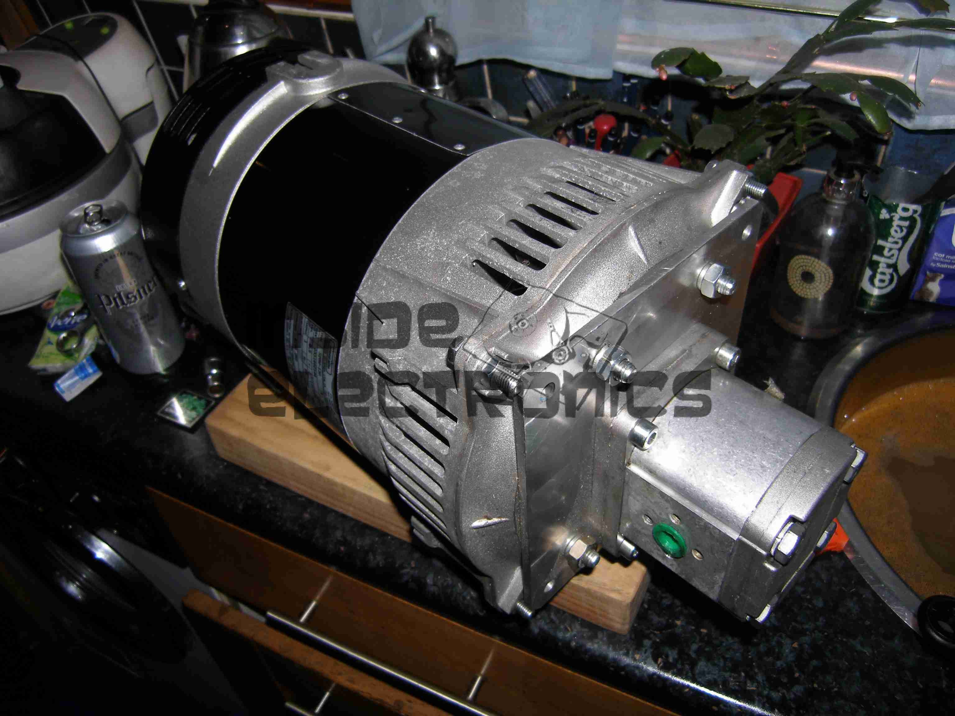
To accompany the previous two posts about hydraulic generators & their components, here is the actual generator unit itself.
Rated at 8.5kVa 230v AC, this will providea mains supply while the narrowboat is away from her home mooring.
This unit will be attached to the side of the hull in the engine room on rubber vibration isolation mounts, behind the main hydraulic oil tank & is driven from the small gear pump attached to the back of the main propulsion hydraulic pump unit.
Operating pressure is 175 bar, 21L/m flow rate to achieve the 3,000RPM rotor speed for 50Hz mains frequency.
While sourcing the main propulsion hydraulic system for nb Tanya Louise in the summer, we thought that it would be convenient to have an on board generator that didn’t require dragging off the boat & highly explosive petrol to operate.
As the hydraulics were already being fitted, we decided to add a hydraulically driven generator to solve this issue.
And this is where the problems began…
We were referred to Mike Webb of hydraulicgenerators.co.uk to supply the equipment required for this part of the project, this was to include the alternator itself, hydraulic motor to drive the alternator, the required adaptor plates to mate the motor to the generator head & a control valve block to regulate the oil flow & pressure to the motor.
After a phone call to Mike on 16-07-2013 to discuss our requirements, we settled on a system. I received the following E-Mail the next day from Mike:
Good morning, reference our conversation, Martin from BSP has given me details as to what he will be supplying, on that basis and in light of the special price I have offered, this is what I propose to supply,
1 off New 8kVa – 7kW Hydraulic driven generator 220v single phase 50hz c/w flow control valve, pressure relief valve and on/off solenoid valve, Martin did say that the engine idle is between 1000 and 1200 rpm and max speed is 3600 rpm, valves will be rated accordingly. I have the alternator and parts available now, in order for me to be able to offer this at a significantly discounted price of £ 1.200.00 nett, I will need to utilise the components I have in stock now, so I will need payment asap, delivery will be approx. 7 days, primarily due to the fact that the coupling is fabricated to suit, I can either deliver the unit to you when ready or BSP or hold onto it until everything else is in place. The alternator is a Meccalte S20W that I bought for another customer a few weeks ago, but he cancelled and I don’t have, at this time, anyone else interested in it, so either I do a deal with you at the above price or wait until someone else comes along and wants the unit.
With regards to installation, let me know if you need any help, but it would be best to install when the engine is being installed and the rest of the system hosed up, I assume BSP will be sorting this, in which case I’ll liase with Martin.
I trust that this meets with your approval and look forward to hearing from you.
At this point an order was placed with Mike, & the money transferred so he could begin building the unit for us. As can be seen from the E-Mail, a lead time of 7 days was stated.
After a few phone calls over the following month, firstly being told that the custom parts to mate the generator to the motor had not come back from the engineers, I sent another E-Mail to Mike on 10-09-2013, and got no reply.
Following another phone call, I was told that the generator had been shipped, however Mike would not give me any tracking details for the shipment, and would not initially tell me who it was shipped with.
Again the generator didn’t turn up.
More phone calls ensued & I was told at this point that the shipping company had been confused by the address given, shipped back to Mike. At this point I was informed that the shipping company had actually LOST it. Several more phone calls later I was promised that a replacement generator would now ship no later than 08-10-2013. A follow up E-Mail two days later also generated no reply.
At this point I was beginning to wonder if I would ever see the goods we had paid for, but finally a shipment arrived from Mike
~15-10-2013, over TWO MONTHSafter our promised delivery date. However, even having been delivered, all was not well with the goods.
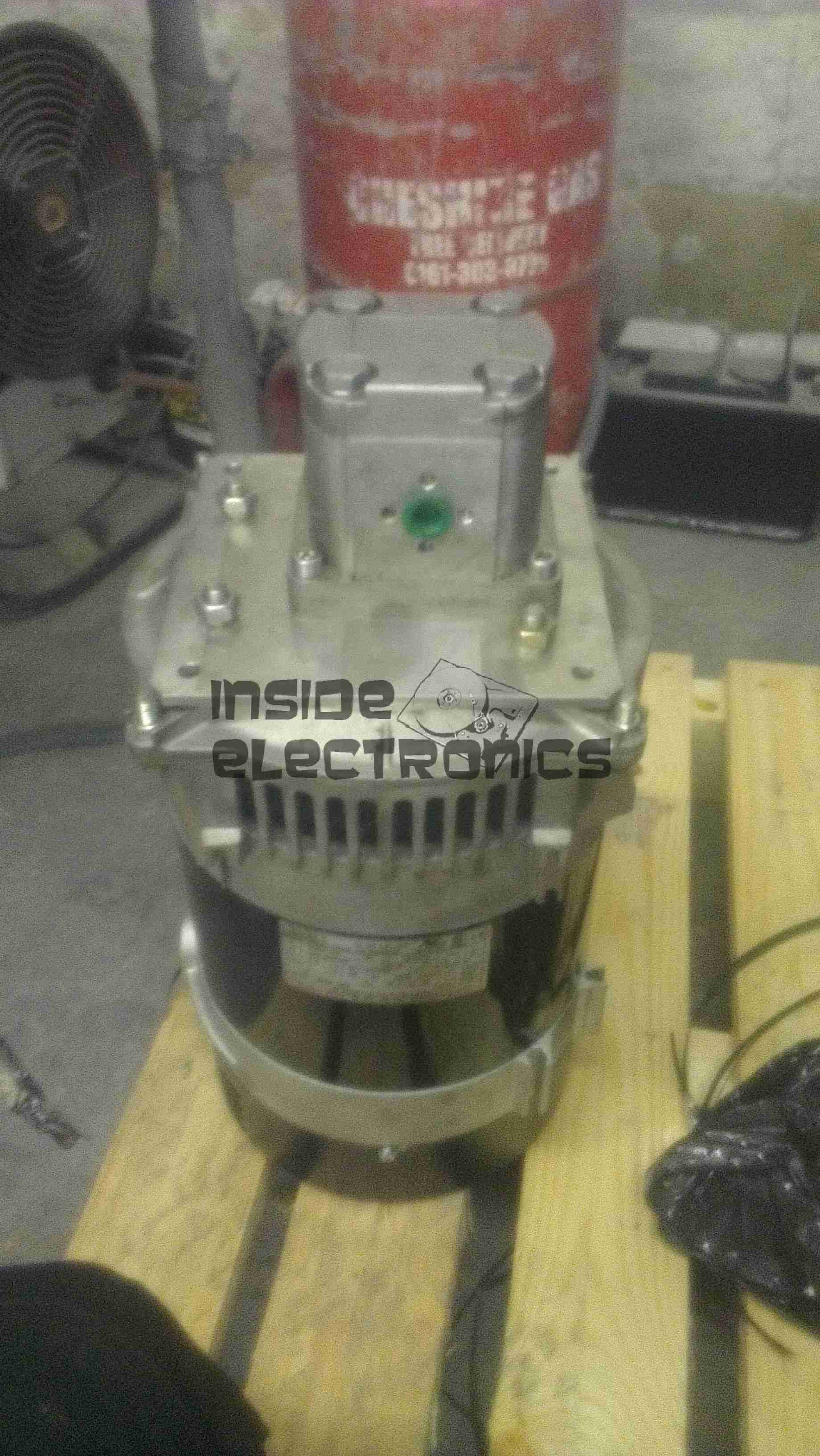
Generator Pallet
Above is the generator supplied. No mounting bracket, no integrated valve block, in short, nothing like what was described in Mike’s documentation & website. The original documentation is available here for reference: [download id=”5564″]
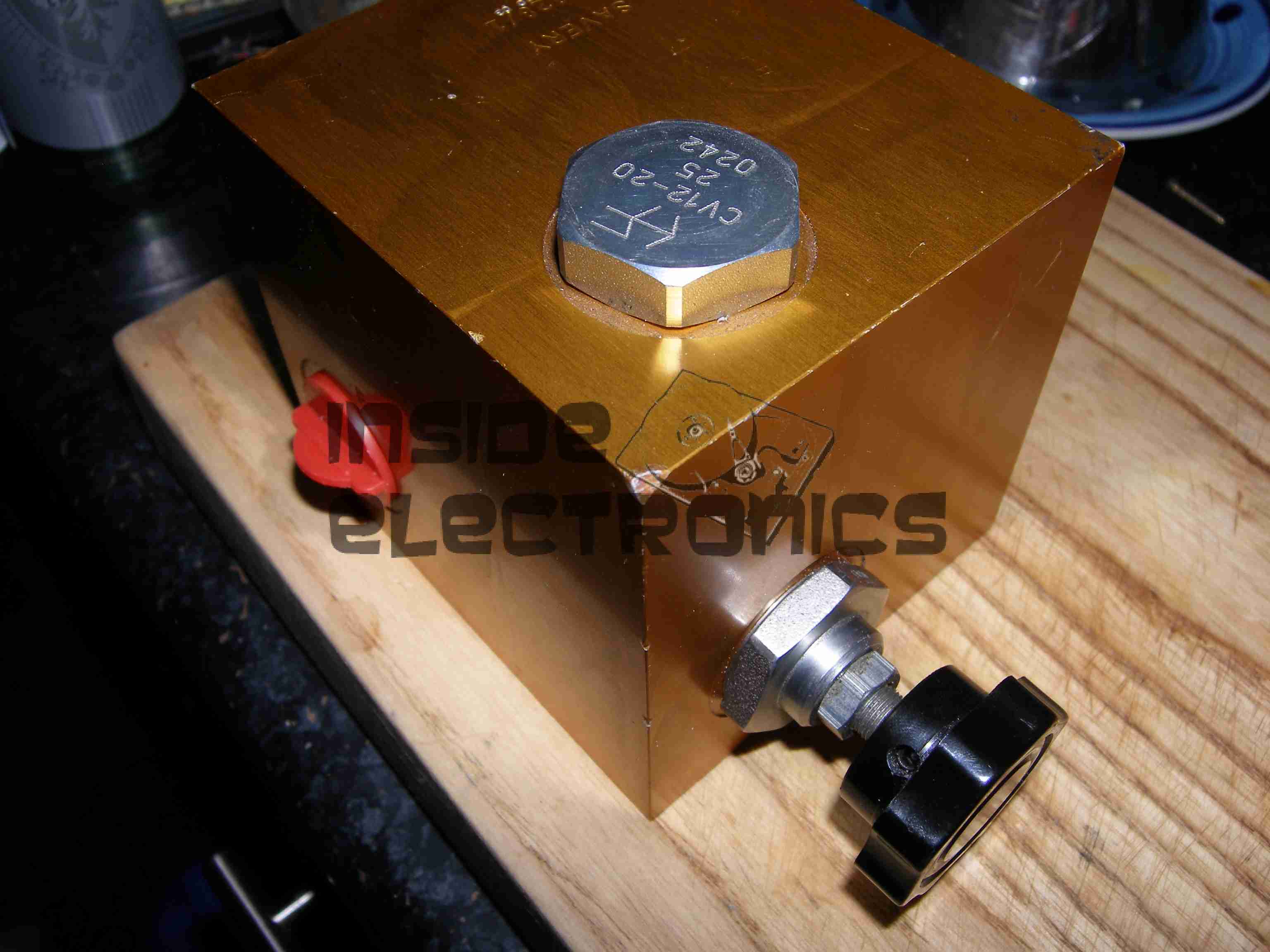
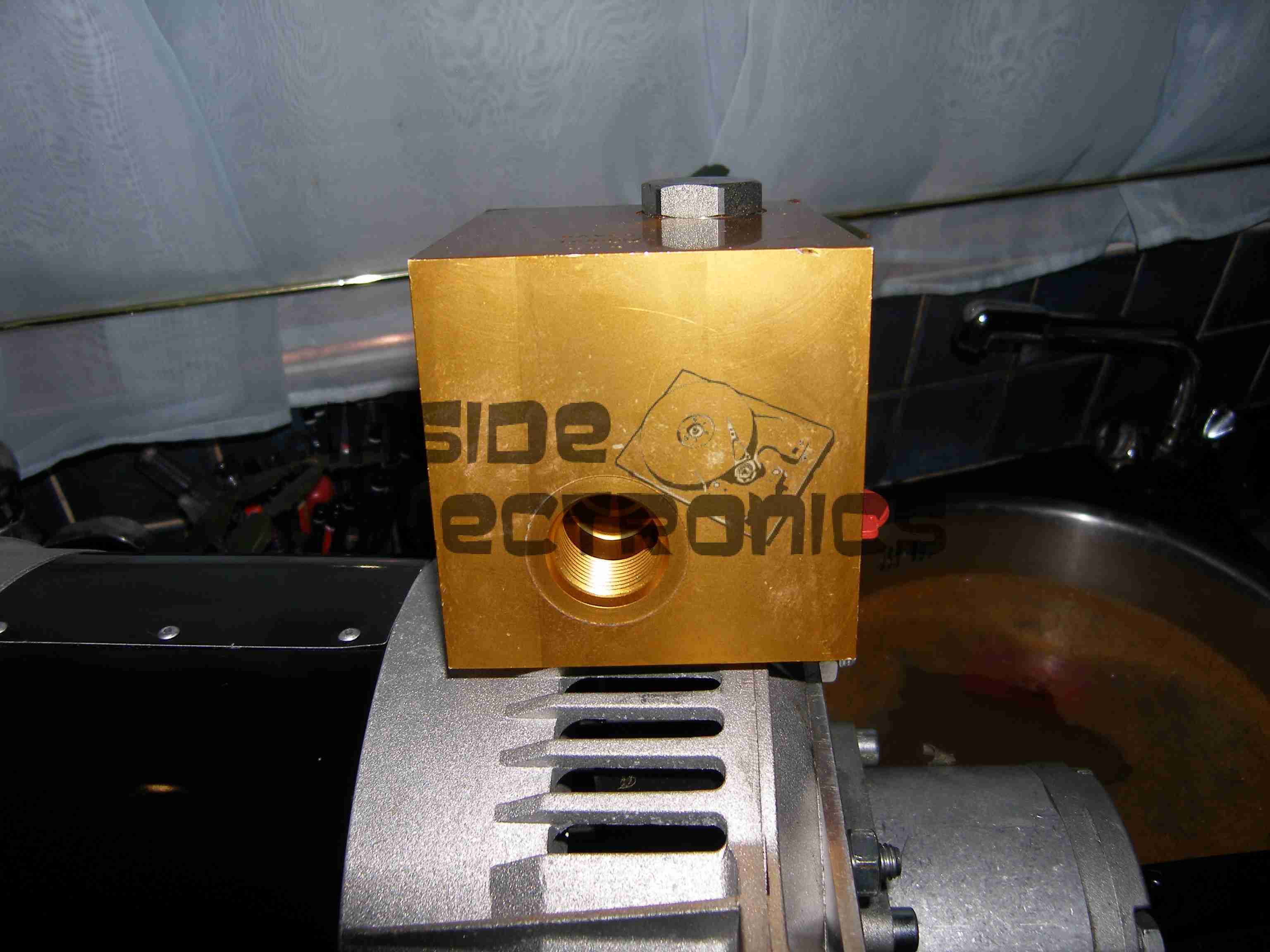
As can be seen, there is an open port on the side of the valve block. This is where the ON/OFF control solenoid valve is supposed to be located.
After several more unanswered E-Mails & phone calls, I had to get somewhat more forceful in my messages, as now Mike had begun outright lying about what was specified in the original order. In which that there was no solenoid valve required. So the following E-Mail was sent 21-10-2013:
Mike,
Having had a conversation with Martin, about him attempting to contact you regarding what you have supplied to us, I need this resolving ASAP now, as I am being held up by the fact that there is an open port on your valve block where the solenoid control valve is supposed to be located.
As it stands the valve block & therefore the generator you have supplied to us is useless for it’s intended purpose & I will be seeking legal advice on this matter if a resolution cannot be made this week, considering you have not replied to any E-Mail I have sent since the unit’s massively delayed arrived.
In your original correspondence it is certainly indicated that this valve was to be fitted, which was also Martin’s instruction to you.
I await your expedient response.
This threat of legal action actually spurred a response from Mike, who finally replied with the following on 25-10-2013:
Ben,
Sorry about all this, I have been away and down with a bug for the last week, I will sort this today and will have the required parts shipped to you on Monday for Tuesday delivery.
Regards
Mike
Another promise of a delivery date, so I waited a little longer, until the Friday of that week. Still no delivery. No surprise there then.
(I didn’t believe the story about illness either).
At this point I again attempted contact, but got nowhere, even with legal threats. So I’ve given up completely on this & been forced to source the parts elsewhere at extra cost.
This company is not the one to go to if you require a hydraulic generator unit for any application, as you’d be lucky to get any part of what you order on time, if at all.
Operations are run by an all out liar who seems to be happy to accept money but not ship the goods that had been paid for.
Mike having explained to me that the shipping company had lost a generator, and he would have to build me another one to replace it also does not make sense, as in the initial phone call & mail he stated that the Meccalte generator that we eventually received was a single unit that was specially ordered for another client, and the factory build date on the unit certainly gave away the fact that the generator head had been sat around for some considerable time before I came along & made a purchase.
Hopefully this post will get a high Google ranking, to ensure that anyone else who happens to be looking for a similar piece of equipment does not have the misfortune to trust this man.
We were referred to him on good faith & unfortunately in this case it did not go well.
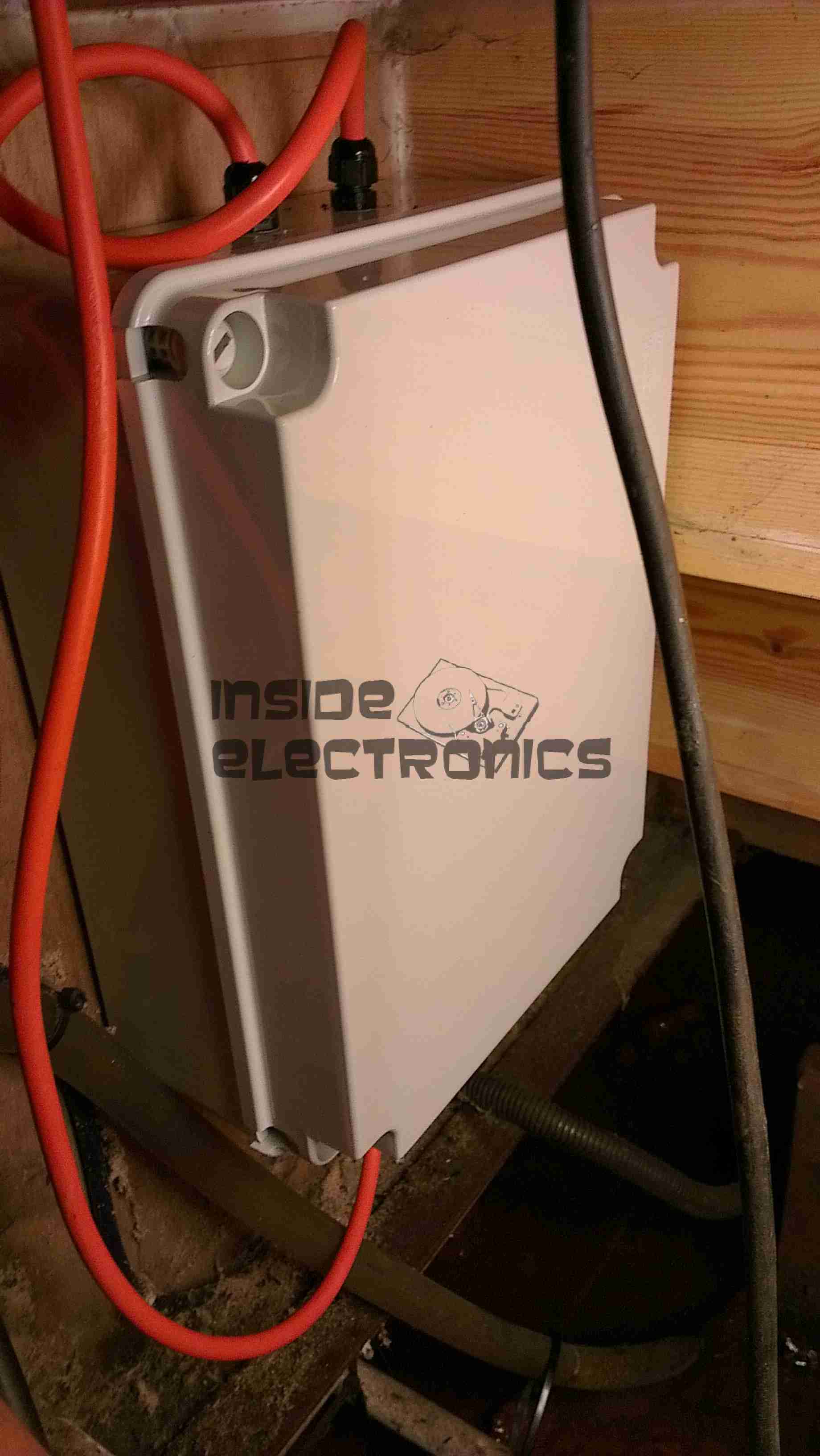
Here is the latest build & addition to the boat, in preparation for delivery of an 8kVa hydraulically driven generator unit – an automatic transfer switch.
Above can be seen the completed contactor unit, mounted in the engine bay.
This unit takes feeders from both the shore power socket & the generator unit & switches them independently through to the domestic 240v AC systems on board.
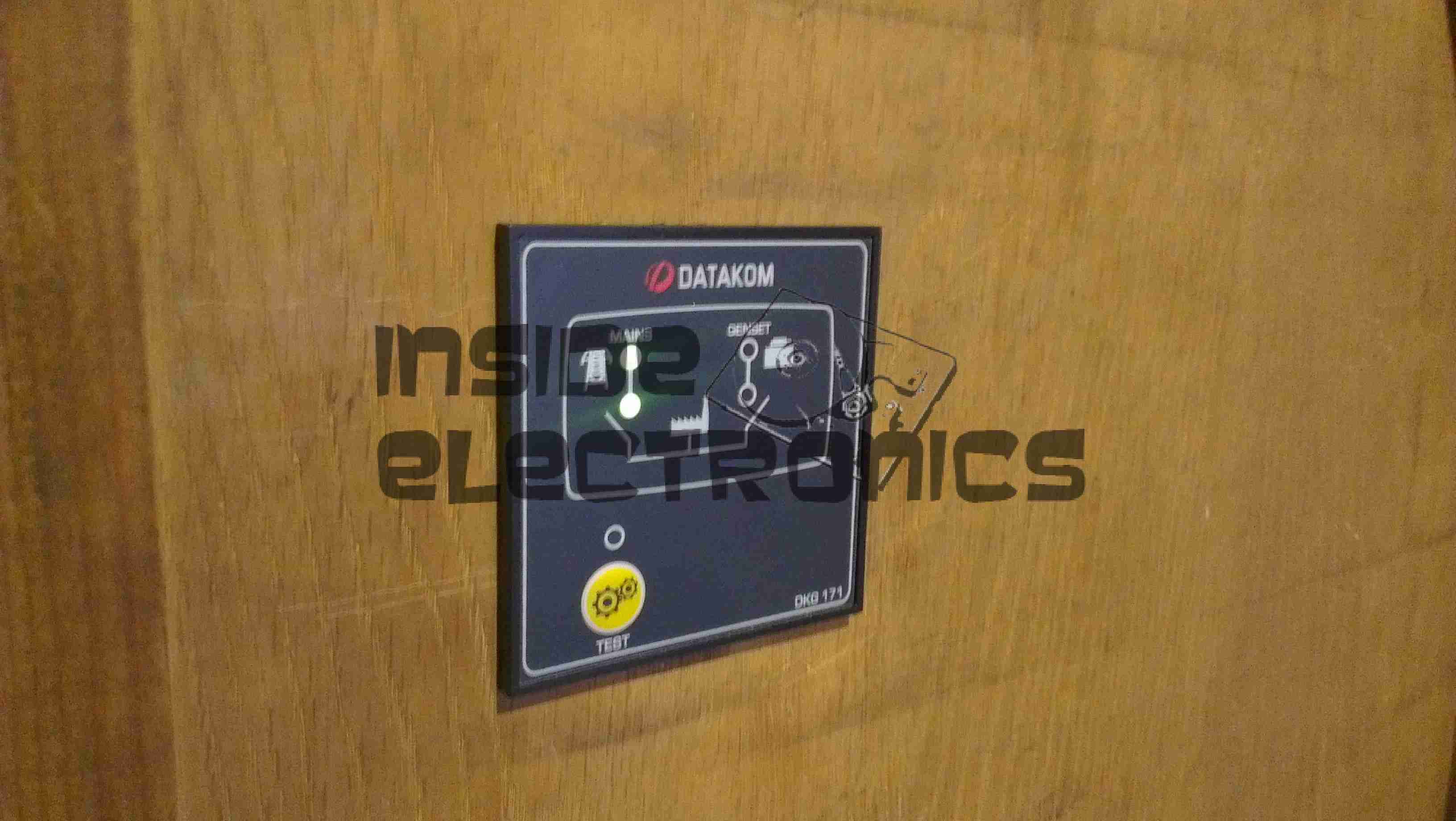
Contactor switching is done by a Datakom DKG-171 automatic generator controller.
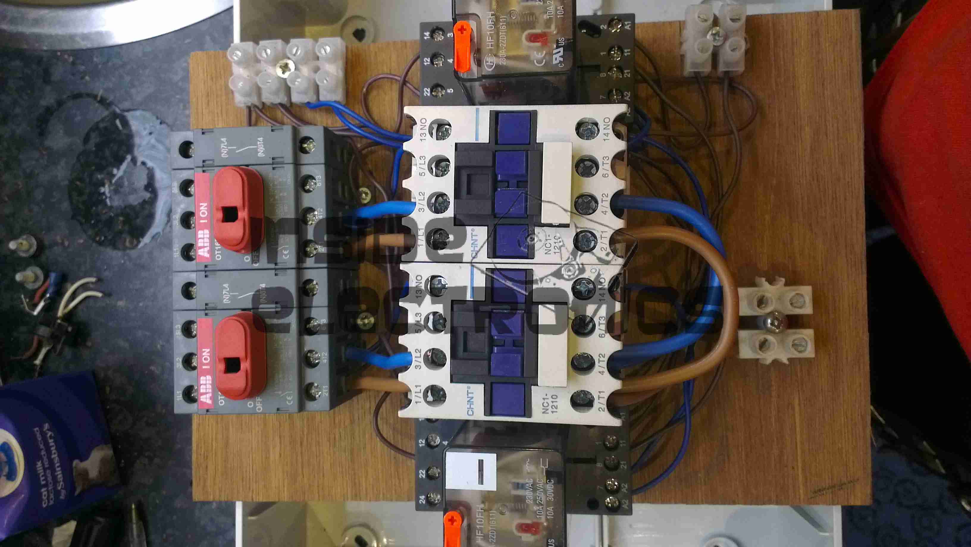
Switching Unit
Here are the contactors & isolators, before fitting to the wallbox. Power comes in one the left, through the large 25A isolating switches, before feeding to a pair of 30A contactors. The pair of outer relays next to the contactors are interlocks. These ensure that when one contactor is energized, the other is electrically locked out. Even if the interlock relay is manually operated with the orange flag visible on the top of the unit, they are wired to de-energize both contactors. This ensures that under no circumstances can both power sources be connected at the same time.
Panel Cutout
The generator controller requires a 68mmx68mm panel cutout for mounting. This was done in the main panel next to the electrical locker.
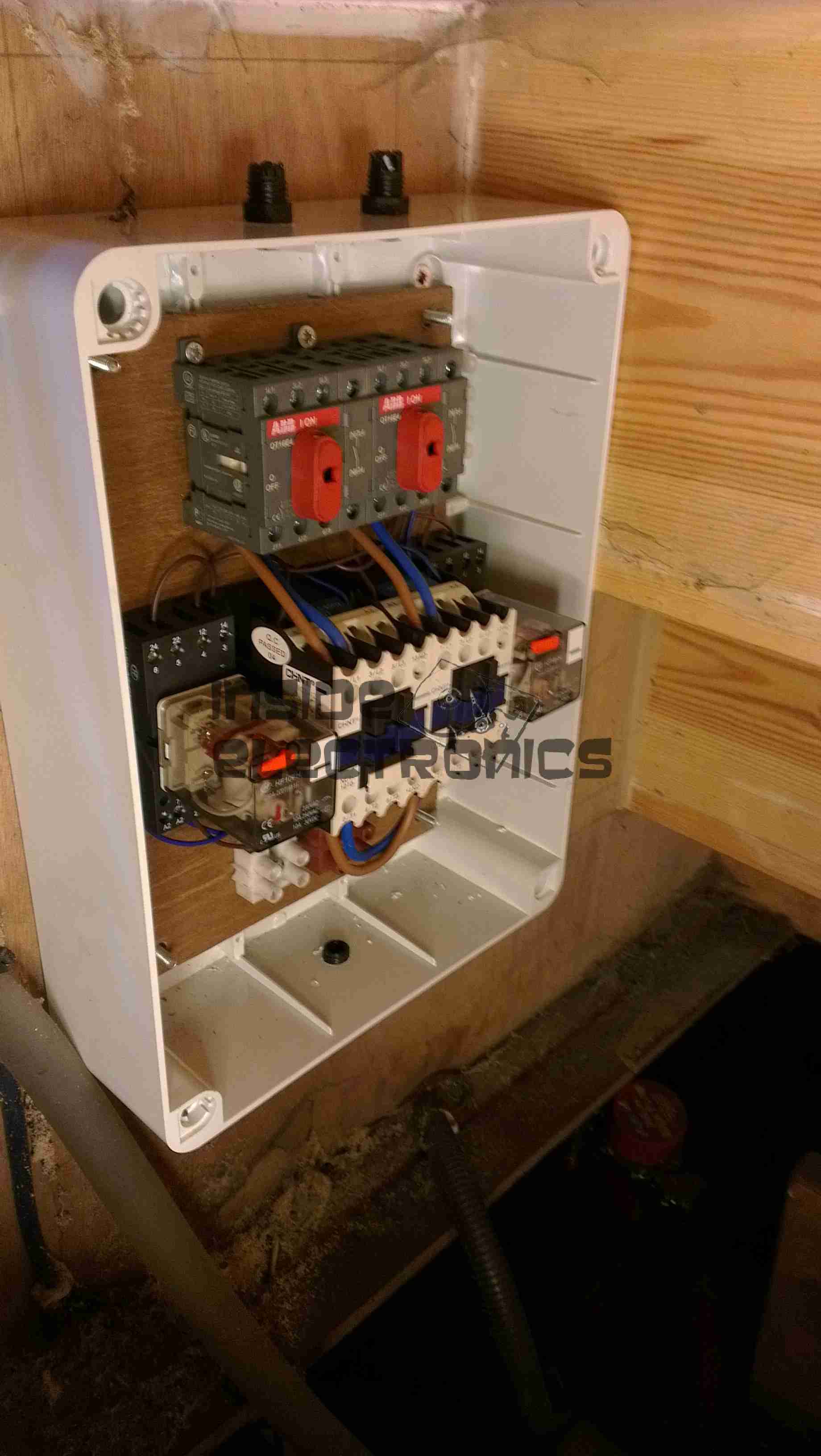
Box Fitted
Here the contactor board has been fitted into the wallbox & the cable glands fitted before wiring.
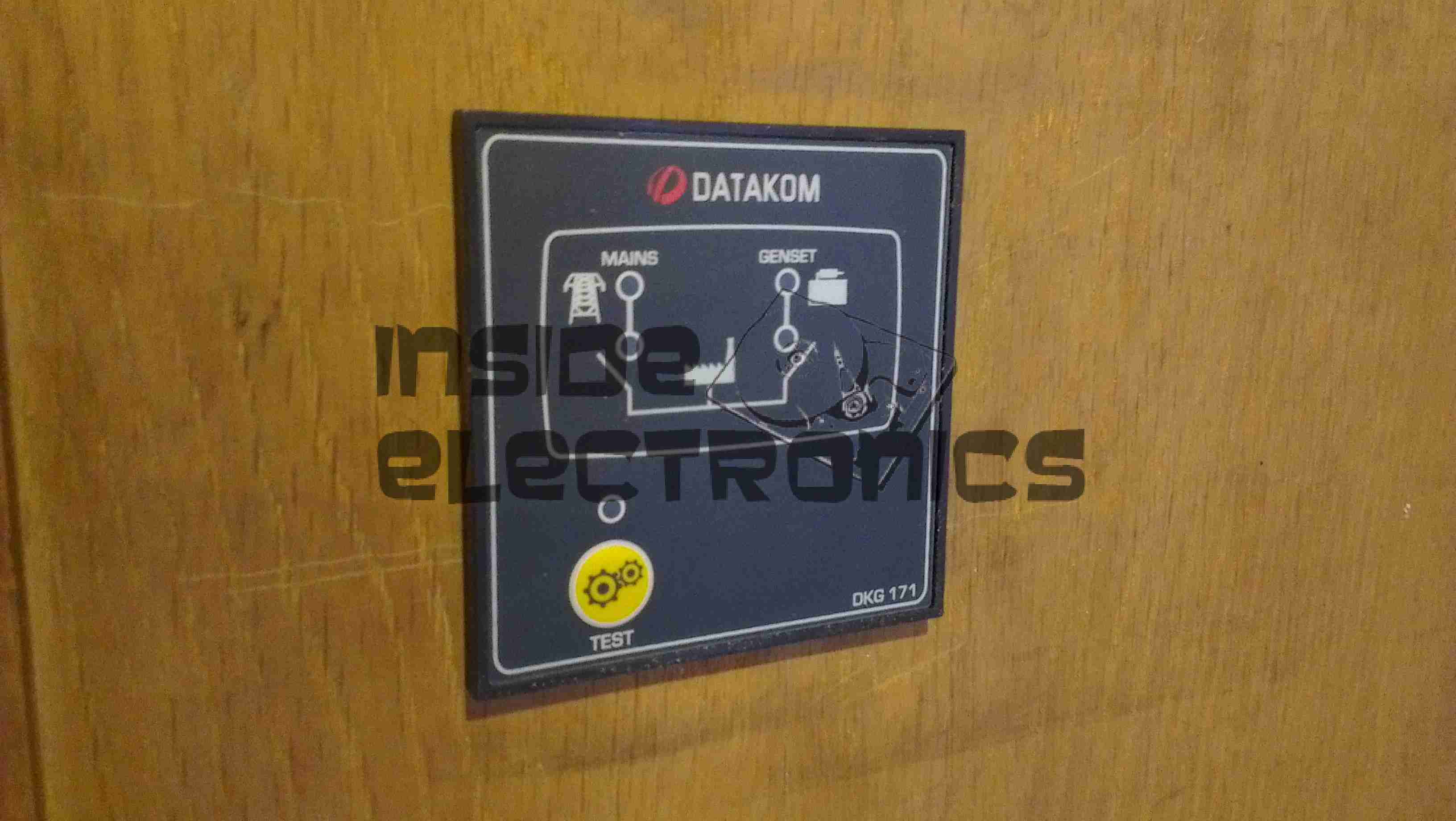
DKG-171System Online
The generator controller fitted & finally energized. The indicator LEDs on the front of the unit let the user know where power is currently being supplied from & which contactor is energized.
Finally, some protection for my Raspberry Pi! The PCB fit is slightly loose, but that was quickly sorted with the application of a couple of spots of hot glue in the corners.
Unfortunately, the case is a couple of mm too small to fit the main board from the Pico Projector inside, so I won’t be butchering that into the case with the Pi as yet. What is required is an interface to the display engine from the Pi’s DSI interface.
Pi Cased Up
The pi all boxed. up. The only thing that this case would now require is a lightpipe to direct the LED’s light to the openings in the case, as they are very difficult to see at present.
This is the teardown of a Zebra P330i plastic card printer, used for creating ID cards, membership cards, employee cards, etc. I got this as a faulty unit, which I will detail later on.
This printer supports printing on plastic cards from 1-30mils thick, using dye sublimation & thermal transfer type printing methods. Interfaces supplied are USB & Ethernet. The unit also has the capability to be fitted with a mag stripe encoder & a smart card encoder, for extra cost.
Print Engine
On the left here is the print engine open, the blue cartridge on the right is a cleaning unit, using an adhesive roller to remove any dirt from the incoming card stock.
This is extremely important on a dye sublimation based printing engine as any dirt on the cards will cause printing problems.
Cards In Feeder
Here on the right is the card feeder unit, stocked with cards. This can take up to 100 cards from the factory.
The blue lever on the left is used to set the card thickness being used, to prevent misfeeds. There is a rubber gate in the intake port of the printer which is moved by this lever to stop any more than a single card from being fed into the print engine at any one time.
Card Feeder Belt
Here is the empty card feeder, showing the rubber conveyor belt. This unit was in fact the problem with the printer, the drive belt from the DC motor under this unit was stripped, preventing the cards from feeding into the printer.
Print Head
Here is a closeup of the print head assembly. The brown/black stripe along the edge is the row of thin-film heating elements. This is a 300DPI head.
Print Station
This is under the print head, the black roller on the left is the platen roller, which supports the card during printing. The spool in the center of the picture is the supply spool for the dye ribbon.
In the front of the black bar in the bottom center, is a two-colour sensor, used to locate the ribbon at the start of the Yellow panel to begin printing.
LCD PCB
Inside the top cover is the indicator LCD, the back of which is pictured right.
This is a 16×1 character LCD from Hantronix. This unit has a parallel interface.
LCD
Front of the LCD, this is white characters on a blue background.
Roller Drive Belts
Here is the cover removed from the printer, showing the drive belts powering the drive rollers. There is an identical arrangement on the other side of the print engine running the other rollers at the input side of the engine.
Mains Filter
Here the back panel has been removed from the entire print engine, complete with the mains input wiring & RFI filtering.
This unit has excellent build quality, just what is to be expected from a £1,200+ piece of industrial equipment.
Main Frame With Motors
The bottom of the print engine, with all the main wiring & PCB removed, showing the main drive motors. The left hand geared motor operates the head lift, the centre motor is a stepper, which operates the main transmission for the cards. The right motor drives the ribbon take up spindle through an O-Ring belt.
Feeder Drive Motor
Card feeder drive motor, this connects to the belt assembly through a timing belt identical to the roller drive system.
All these DC geared motors are 18v DC, of varying torque ratings.
Power Supply
Here is the main power supply, a universal input switch-mode unit, outputting 24v DC at 3.3A.
PSU Label
PSU info. This is obviously an off the shelf unit, manufactured by Hitek. Model number FUEA240.
Print Engine Rear
The PSU has been removed from the back of the print engine, here is shown the remaining mechanical systems of the printer.
Print Engine Components
A further closeup of the print engine mechanical bay, the main stepper motor is bottom centre, driving the brass flywheel through another timing belt drive. The O-Ring drive on the right is for the ribbon take up reel, with the final motor driving the plastic cam on the left to raise/lower the print head assembly.
The brass disc at the top is connected through a friction clutch to the ribbon supply reel, which provides tension to keep it taut. The slots in the disc are to sense the speed of the ribbon during printing, which allows the printer to tell if there is no ribbon present or if it has broken.
RFID PCB
Here is a further closeup, showing the RFID PCB behind the main transmission. This allows the printer to identify the ribbon fitted as a colour or monochrome.
The antenna is under the brass interrupter disc on the left.
I/O Daughterboard
The I/O daughterboard connects to the main CPU board & interfaces all the motors & sensors in the printer.
Main PCB
Here is the main CPU board, which contains all the logic & processing power in the printer.
CPU
Main CPU. This is a Freescale Semiconductor part, model number MCF5206FT33A, a ColdFire based 32-bit CPU. Also the system ROM & RAM can be seen on the right hand side of this picture.
Ethernet Interface
Bottom of the Ethernet interface card, this clearly has it’s own RAM, ROM & FPGA. This is due to this component being a full Parallel interface print server.
Ethernet Interface Top
Top of the PCB, showing the main processor of the print server. This has a ferrite sheet glued to the top, for interference protection.
Tip Jar
If you’ve found my content useful, please consider leaving a donation by clicking the Tip Jar below!
All collected funds go towards new content & the costs of keeping the server online.