Posted on Leave a comment

Inductive Hour Counter / Tachometer – Petrol Engines

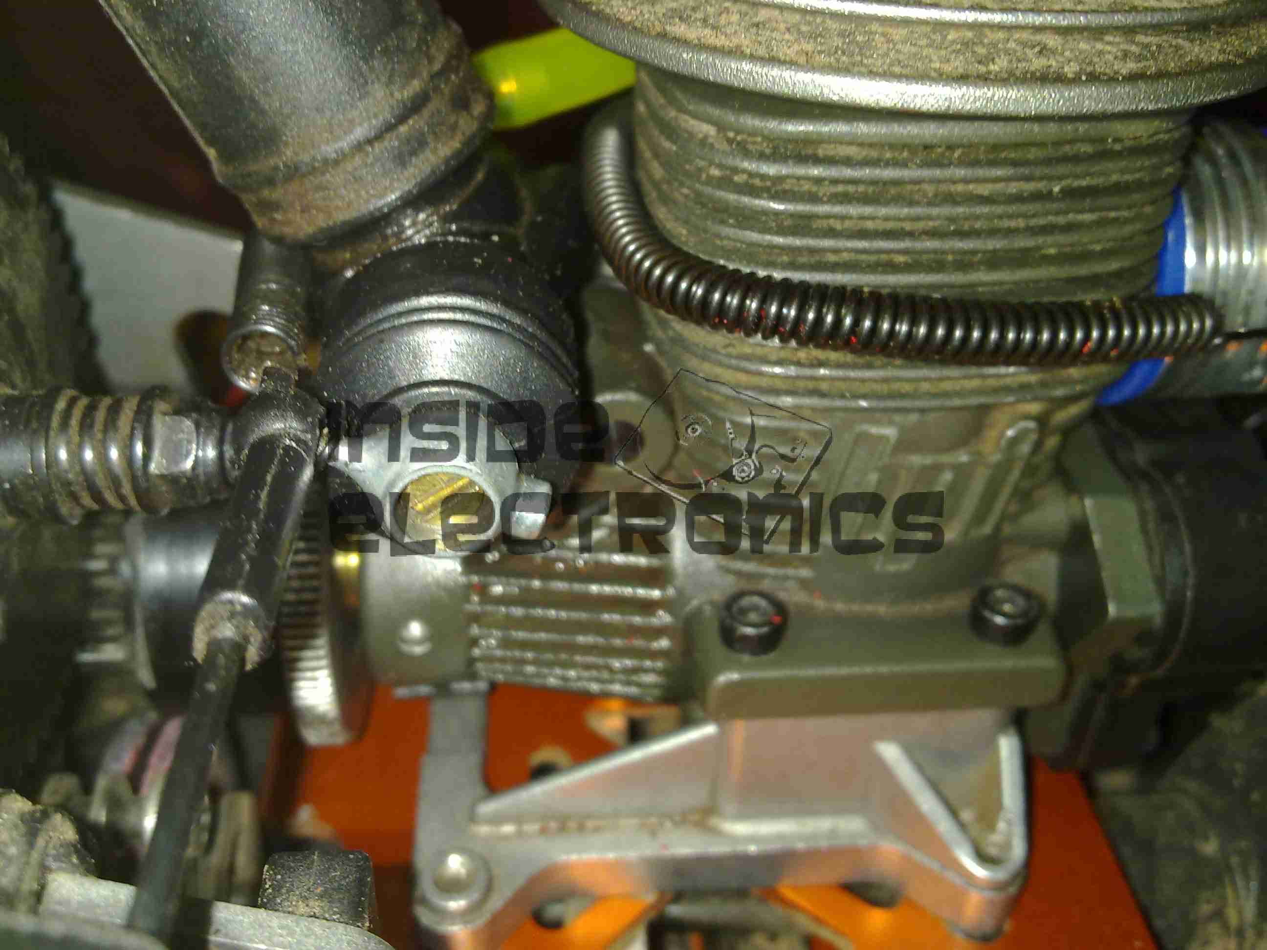
As one of my current projects involves a small petrol engine – a Honda GX35 clone, I figured an hour counter would be very handy to keep an eye on service intervals. (More to come on the engine itself later on). I found a device that would suit my needs on good old eBay.

Inductive Engine Monitor

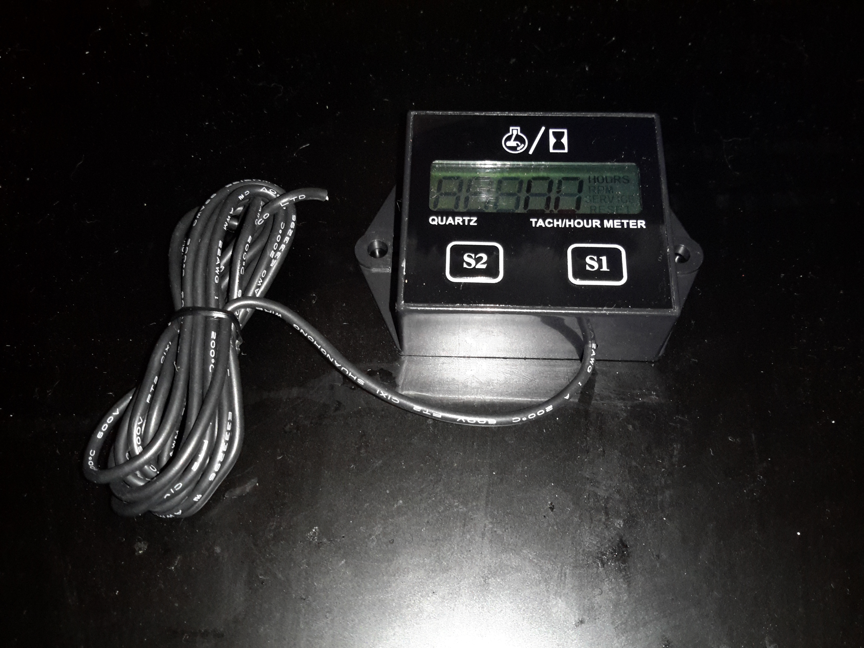
These engine monitors are pretty cheap, at about £4. The sensing is done by a single heat-resistant silicone wire, that wraps around the HT lead to the spark plug. The unit can be set for different firing intervals via the buttons. In the case of most single-cylinder 4-stroke engines, the spark plug fires on every revolution – wasted-spark ignition. This simplifies the ignition system greatly, by not requiring the timing signal be driven from 1/2 crankshaft speed. The second “wasted” spark fires into the exhaust stroke, so has no effect.

Internals
Internals

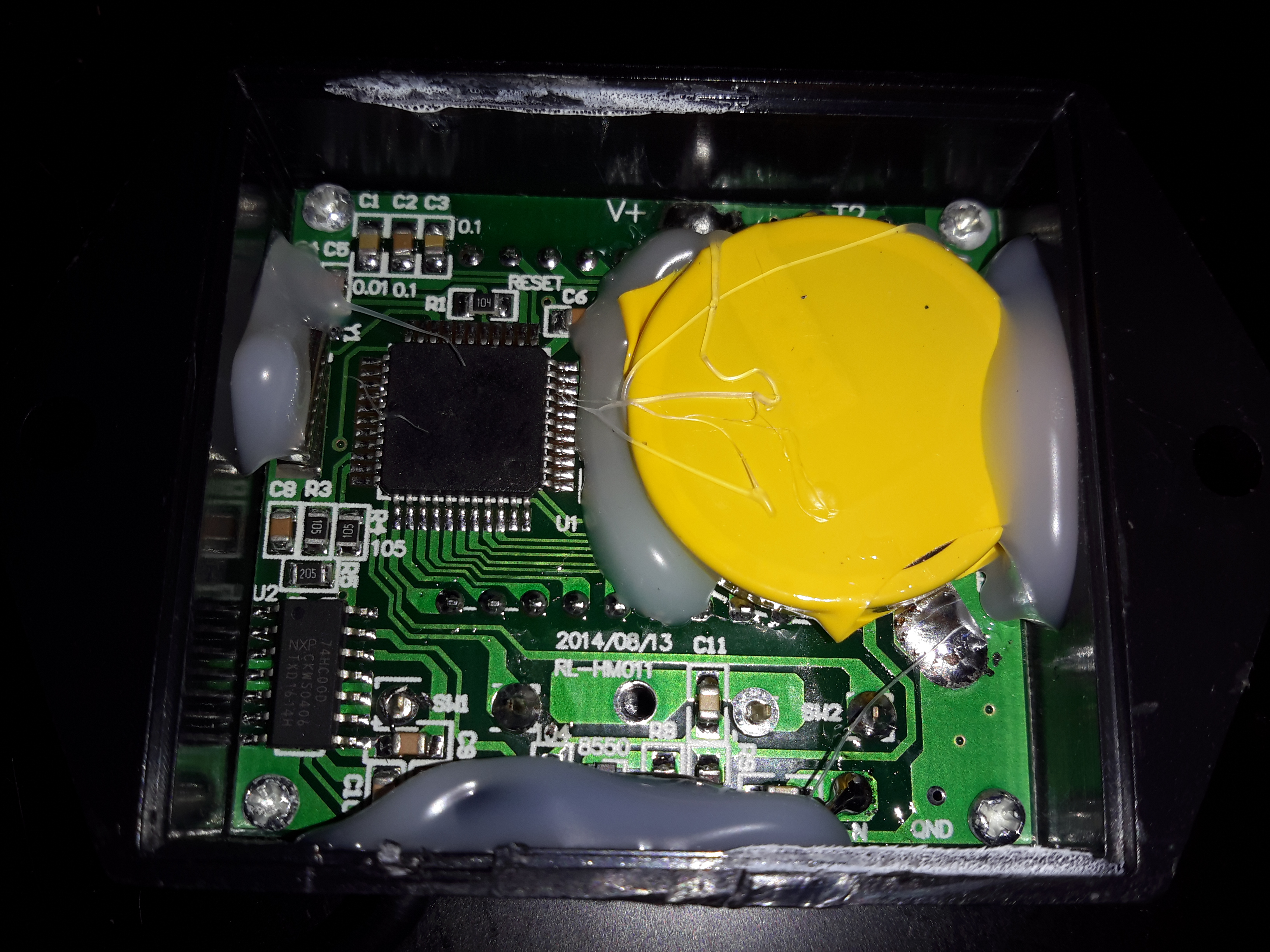
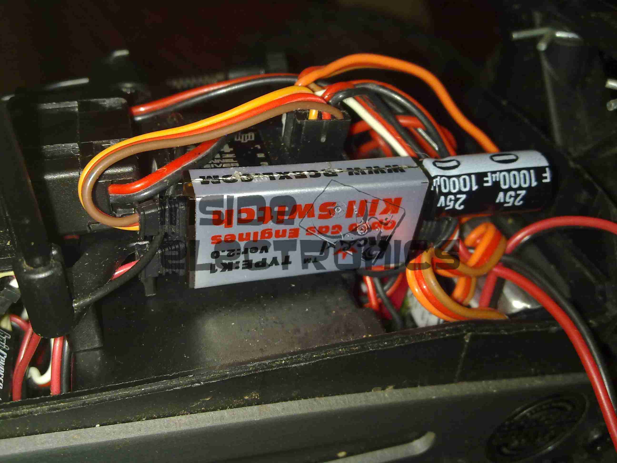
The back cover is lightly glued into place with a drop of cyanoacrylate in opposite corners, but easily pops off. The power is supplied by a soldered-in 3v Lithium cell. The main microcontroller has no number laser etched on to it at all – it appears it skipped the marking machine.

Input Filtering
Input Filtering

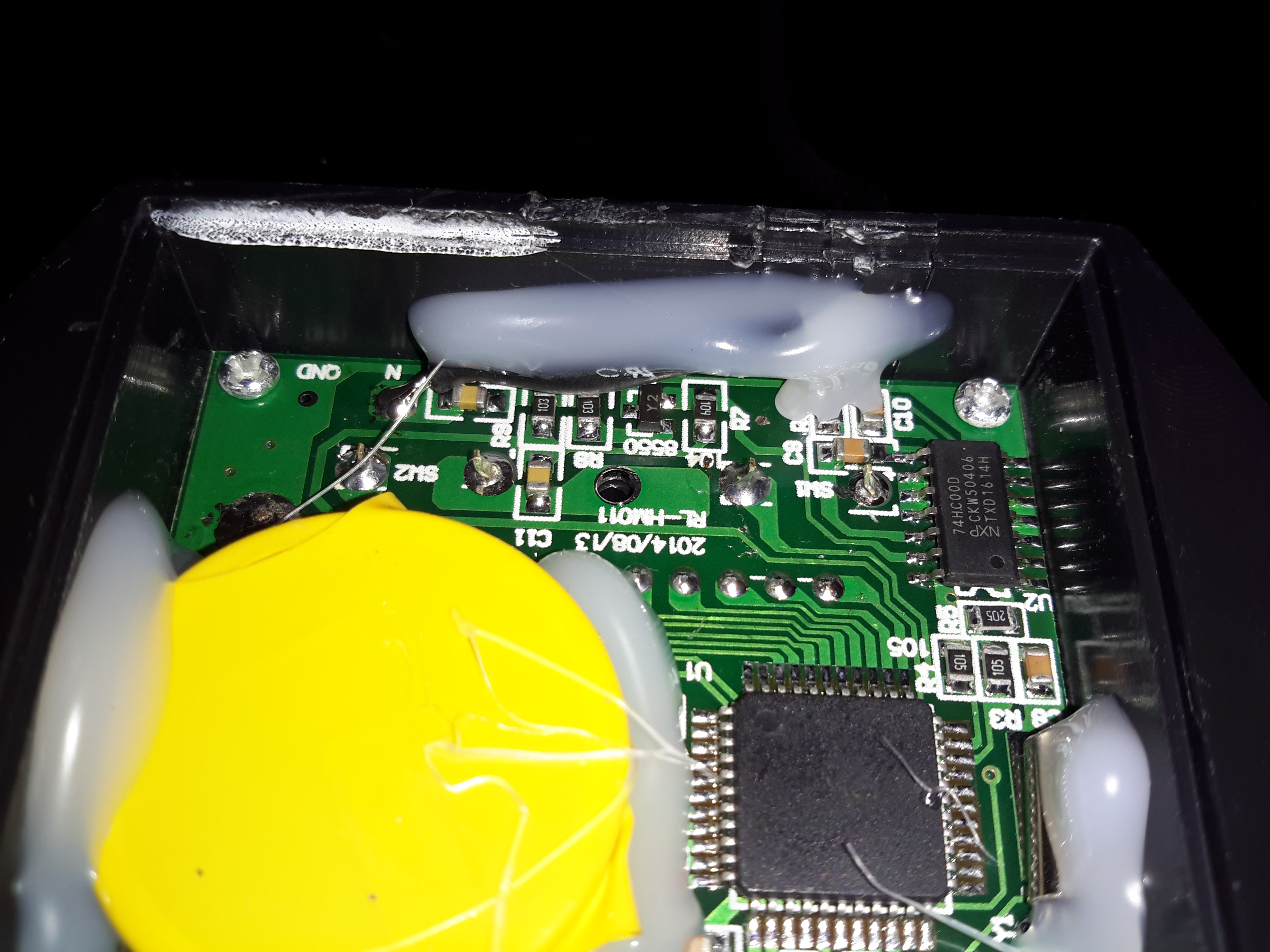
The input from the sensing wire comes in through a coupling capacitor & is amplified by a transistor. It’s then fed into a 74HC00D Quad 2-Input NAND gate, before being fed into the microcontroller.

Pickup
Pickup

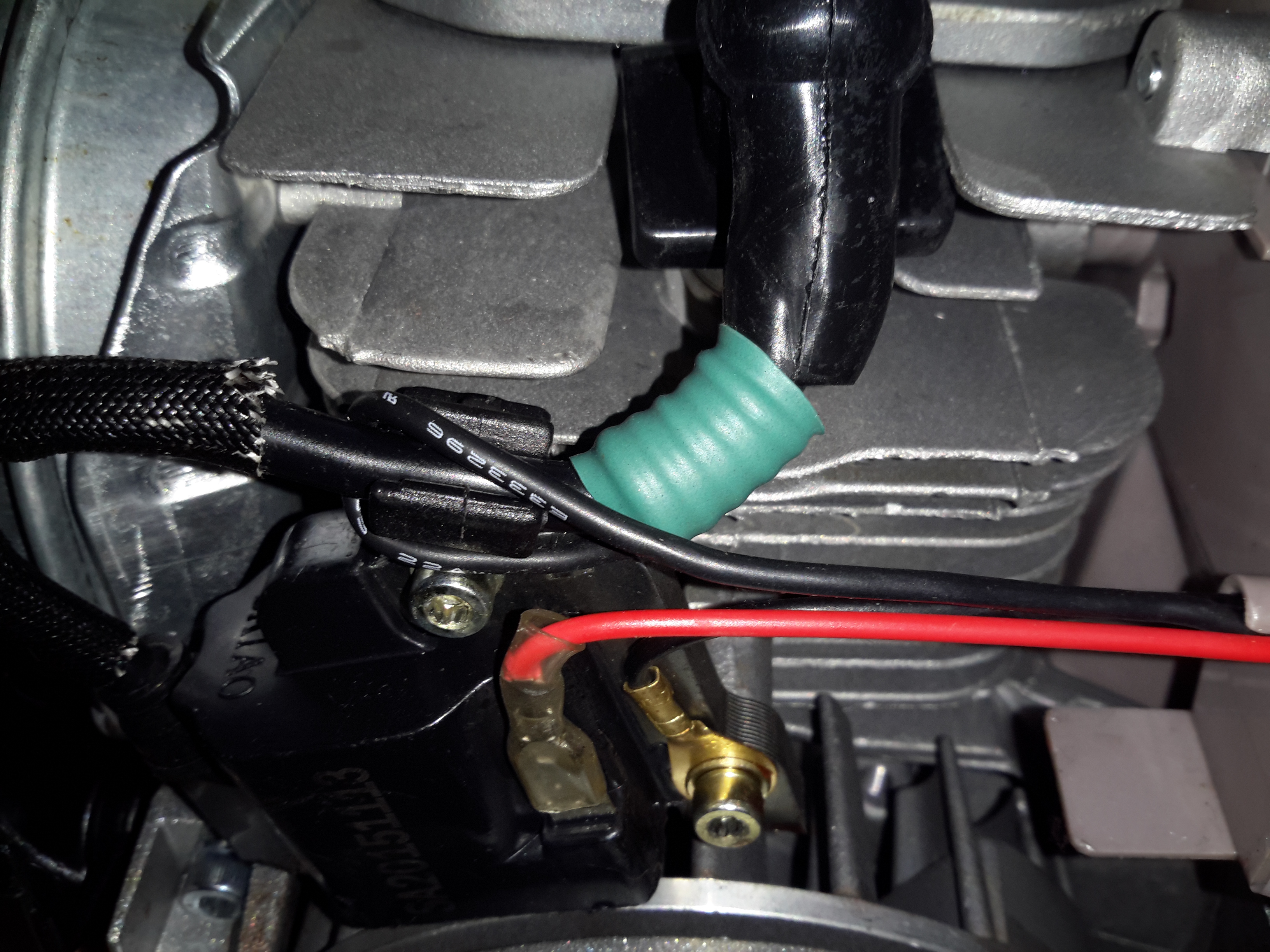
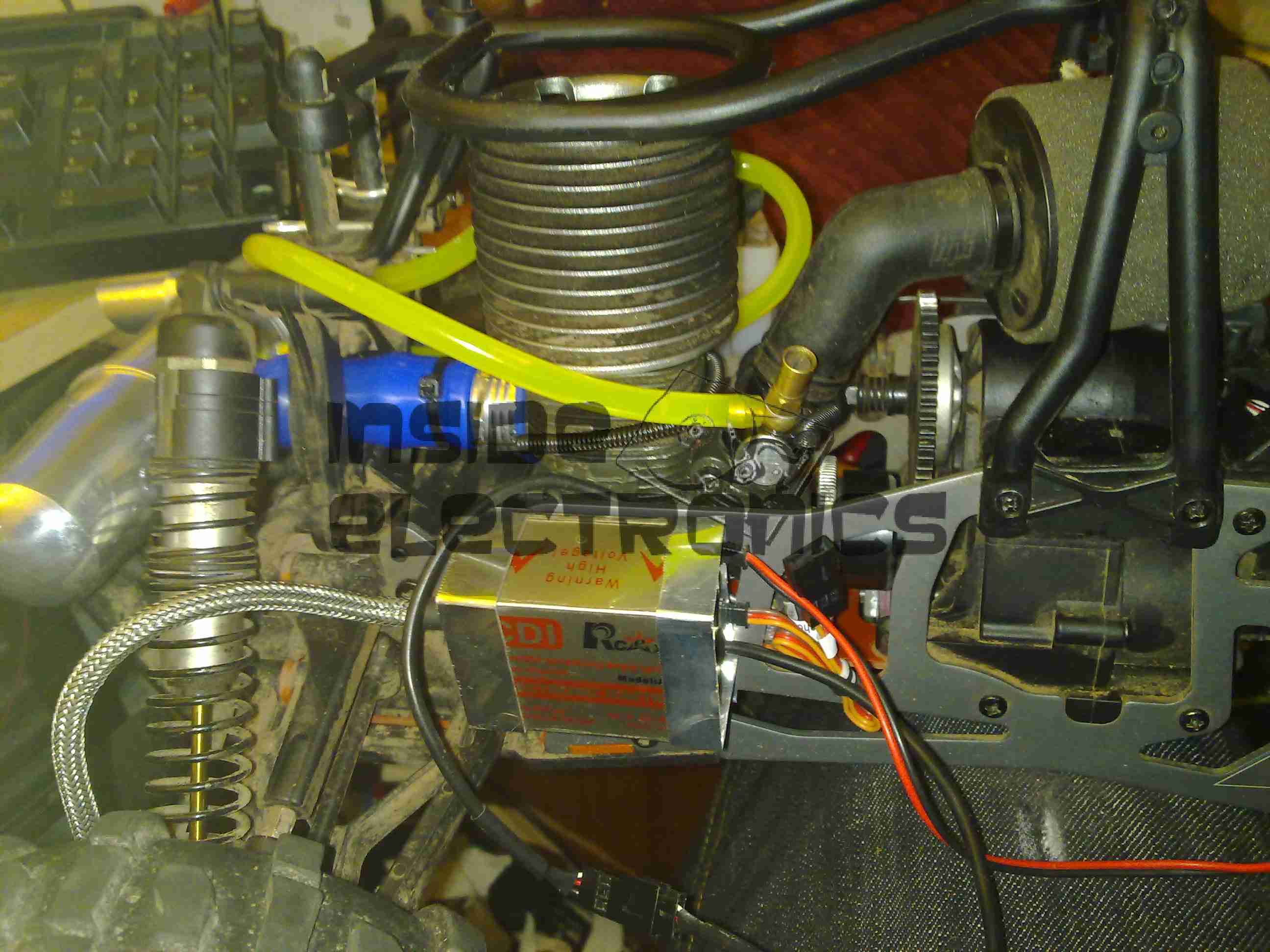
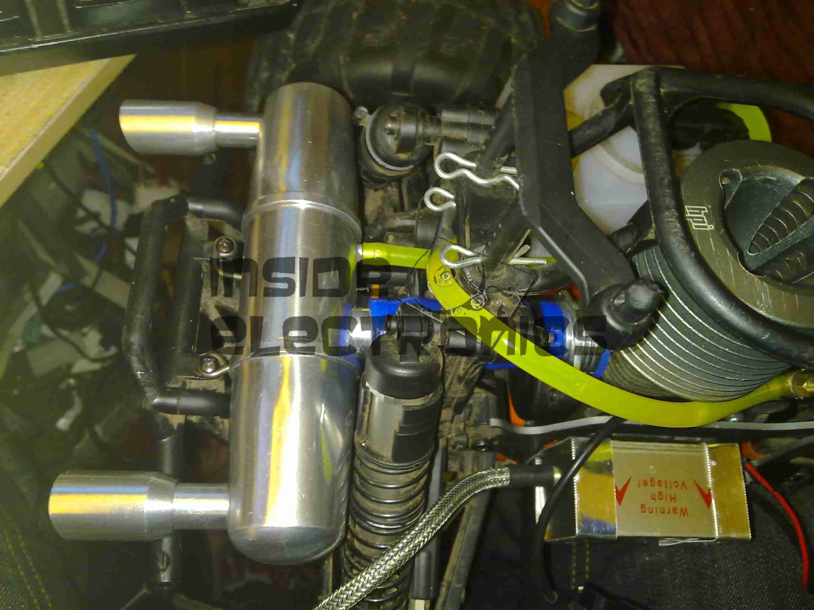
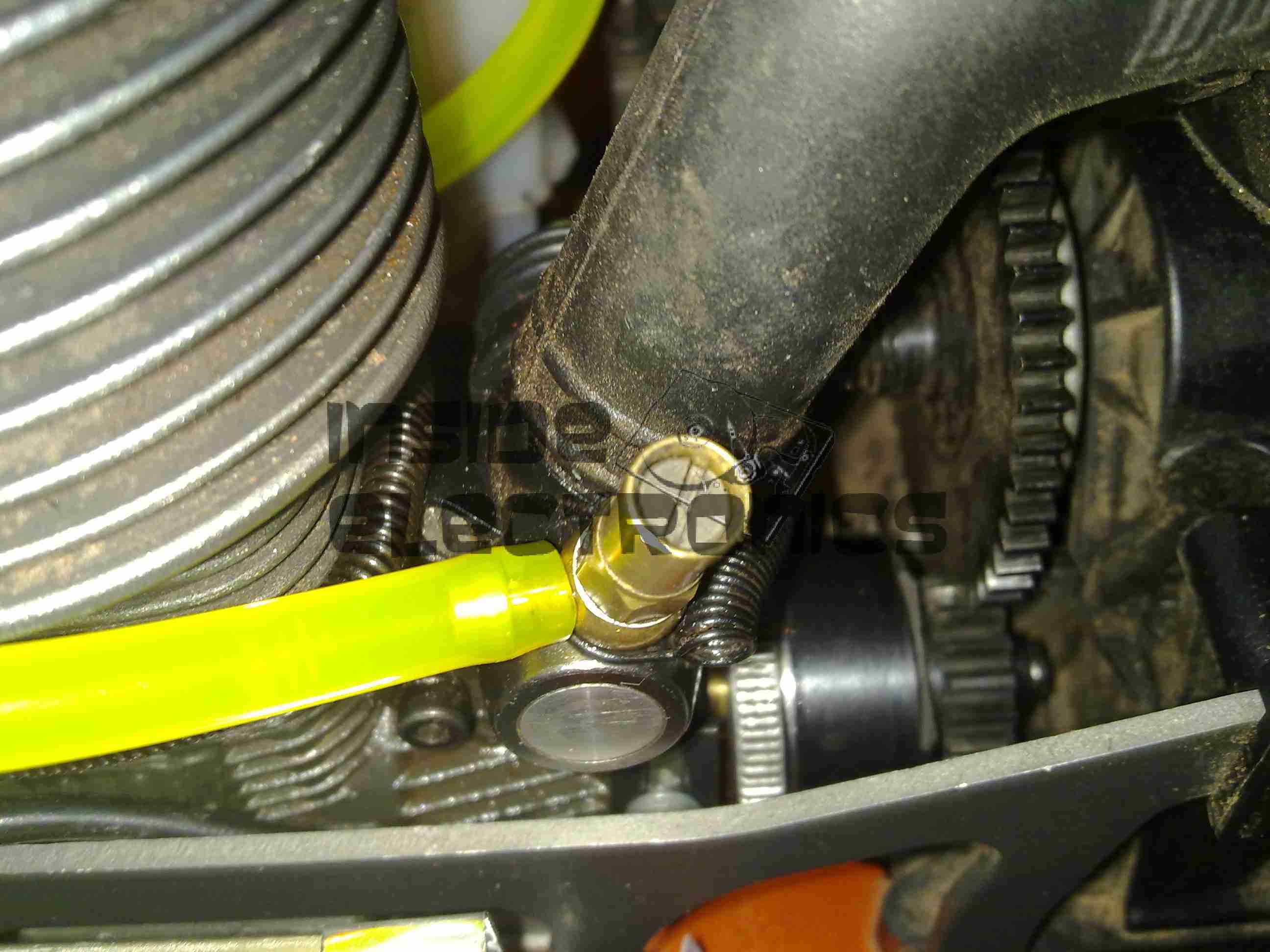
The pickup wire is simply wound around the spark plug lead. I’ve held it in position here with some heatshrink tubing. Heat in this area shouldn’t be an issue as it’s directly in the airflow from the flywheel fan.

Posted on Leave a comment

HPI Savage X 4.6 Ignition Conversion – Initial Carburettor Settings & Module Mountings

Ignition Module Mount
Ignition Module
Ignition Module

The engine now with it’s required ignition sensor, it is now mounted back on the chassis of the model. I have replaced the stock side exhaust with a rear silencer, so I could fit the ignition module in place next to the engine.
For the mounting, I fabricated a pair of brackets from 0.5mm aluminium, bent around the module & secured with the screws that attach the engine bed plate to the TVPs. The ignition HT lead can be routed up in front of the rear shock tower to clear all moving suspension parts, with the LT wiring tucked into the frame under the engine.
In this location the module is within the profile of the model chassis so it shouldn’t get hit by anything in service.

Rear Exhaust
Rear Exhaust

New exhaust silencer fitted to the back of the model. This saves much space on the side of the model & allows the oily exhaust to be discharged away from the back wheel – no more mess to wipe up.

Kill Switch
Kill Switch

The ignition switch fitted into the receiver box. This is wired into channel 3 of the TF-40 radio, allowing me to remotely kill the engine in case of emergency. I have fitted a 25v 1000µF capacitor to smooth out any power fluctuations from the ignition module.
The radio is running from a 11.1v 1Ah 3S LiPo pack connected to a voltage regulator to give a constant 6.5v for the electronics. I found this is much more reliable than the standard 5-cell Ni-MH hump packs.

Fuel Tank
Fuel Tank

The stock silicone fuel tubing has been replaced with Tygon tubing to withstand the conversion to petrol.

High Speed Needle
High Speed Needle

High speed needle tweaked to provide a basic running setting on petrol. This is set to ~1.5mm below flush with the needle housing.

Low Speed Needle
Low Speed Needle

Low speed needle tweaked to provide a basic running setting on petrol. This is set to ~1.73mm from flush with the needle housing.

As petrol is a much higher energy density fuel, it requires much more air than the methanol glow fuel – ergo much leaner settings.
The settings listed should allow an engine to run – if nowhere near perfectly as they are still rather rich. It’s a good starting point for eventual tuning.


Posted on Leave a comment

ICL Barcode Scanner

Top
Top

An ICL barcode scanner from the 80s is shown here. This is the top of the unit with cover on.

Cover Removed
Cover Removed

Plastic cover removed from the unit showing internal components. Main PSU on left, scan assembly in center. Laser PSU & Cooling fan on right. Laser tube at top.

Scan Motor
Scan Motor

Closeup of laser scan motor. This unit scans the laser beam rapidly across the glass plate to read the barcode.

Controller PCB
Controller PCB

View of the bottom of the unit, showing the controller PCB in the centre.

Scan Motor Driver
Scan Motor Driver

The 3-phase motor driver circuit for the scan motor. 15v DC powered.

Laser Unit
Laser Unit

This is the laser unit disconnected from the back of the scanner. HT PSU is on right hand side, beam emerges from optics on left.

Laser Unit Label
Laser Unit Label

This unit is date stamped 1987. The oldest laser unit i own.

Tube PSU
Tube PSU

Laser tube power supply. Input voltage: 24v DC. Output: 1.8kV 4mA.

Laser PSU Board
Laser PSU Board

Rear of HT PSU. Obviously the factory made a mistake or two 🙂

Laser Tube Mounting
Laser Tube Mounting

Top cover removed from the laser unit here shows the 1mW He-Ne tube. Manufactured by Aerotech.

Tube Label
AeroTech He-Ne Tube

Tube label. Manufactured July 1993. Model LT06XR.

Plasma
Plasma

Here the tube has been removed from it’s mount to show the bore down the centre while energized.

OC Mirror
OC Mirror

OC end of the tube shown here lasing.

Beam
Beam

Beam output from the optics on the laser unit.

Tube Optics
Tube Optics

Optics built into the laser unit. Simple turning mirror on adjustable mount & collimating lens assembly.

Scan Lines
Scan Lines

Kind of hard to see but the unit is running here & projecting the scan lines on the top glass.

Laser Tube Mounting
Laser Tube Mounting

Laser tube mounting. A combo of spring clips & hot glue hold this He-Ne tube in place