Here’s an oddity from the 1980’s – a CRT-based portable TV, with a very strangely shaped tube. Sony produced many types of flat CRTs back in the 80’s, with the electron gun at 90° to the curved phosphor screen.
Front Panel
The front panel has the display window, along with the tuning & volume indicators. Unfortunately since analogue TV transmissions have long been switched off, this unit no longer picks up any transmissions off the air, but it can be modified to accept a composite video input.
Back Panel
The back panel has the battery compartment & the tilt stand.
Certification
The certification label reveals this unit was manufactured in May 1984, 32 years ago!
Spec. Label
Rated at 6v, ~2.1W this device uses surprisingly little power for something CRT based.
Battery Holder
The battery holder is a little unique, this plastic frame holds 4 AA cells, for a 6v pack.
Battery Compartment
The battery holder slots into the back of the TV, there’s also an extra contact that the service manual mentions is for charging, so I assume a rechargeable 6v battery pack was also available.
Front Panel Removed
Removing a pair of pin-spanner type screws allows the front glass & screen printed CRT surround to be removed. Not much more under here other than the pair of screws that retain the CRT in the front frame.
Back Cover Removed
Here’s the back cover removed, after unscrewing some very small screws. As per usual with Sony gear, the electronics is extremely compacted, using many flat flex cables between the various PCBs. The main PCB is visible at the back, this has all the deflection circuitry, RF tuner, Video IF, Audio IF, video amplifier & composite circuitry.
CRT Electron Gun & Flyback Transformer
Lifting up the main board reveals more PCBs – the high voltage section for the CRT with the flyback transformer, focus & brightness controls is on the left. The loudspeaker PCB is below this. The CRT electron gun is tucked in behind the flyback transformer, it’s socket being connected to the rest of the circuitry with a flat flex cable.
CRT Rear
Here’s the back of the CRT, the phosphor screen is on the other side of the curved glass back. These tubes must require some additional deflection complexity, as the geometry will change as the beam scans across the screen. There’s a dynamic focus circuit on the schematics, along with extensive keystone adjustments.
Sony 02-JM Flat CRT
Here’s the tube entirely extracted from the chassis. The EHT connection to the final anode is on the side of the tube bell, the curved phosphor screen is clearly visible. The one thing I can’t find in this CRT is a getter spot, so Sony may have a way of getting a pure enough vacuum that one isn’t required.
I’d expect the vertical deflection waveforms to be vastly different on this kind of CRT, due to the strange screen setup. Not much of a beam movement is required to move the spot from the top to the bottom of the screen.
HV Module
No doubt to keep the isolation gaps large, all the high voltages are kept on a separate small PCB with the flyback transformer. This board generates the voltages for the electron gun filament, focus grid & the bias to set the beam current (brightness) as well.
Bare CRT
Here the deflection yoke has been removed from the CRT, showing the very odd shape better. These tubes are constructed of 3 pieces of glass, the bell with electron gun, back glass with phosphor screen & front viewing window glass. All these components are joined with glass frit.
Electron Gun
The electron gun in the neck looks to be pretty much standard, with all the usual electrodes.
Viewing Window
Here’s a view from the very top of the CRT, the curve in the screen is very obvious here. The electron beam emerges from the bell at the back.
FD-20 Schematic
Here’s the full schematic of the entire TV, I extracted this from a service manual I managed to find online.
More to come on hacking this unit to accept a standard composite video input, from something such as a Raspberry Pi!
Looking through eBay recently I came across a great deal on some Helium-Neon laser heads from Melles Griot. While definitely not new, these gas lasers are extremely long-lasting & I figured the tubes inside would make a nice addition to my laser collection. Doing some searching on the model number, these heads are rated at an optical output of 4mW, but depending on how much milage is on the tubes, the output may be a bit higher.
Data Label
I got a pair of the heads, this one was manufactured in July 1988, the other March 1989.
OC End / Classification Label
The OC end of the head has the laser classification label & the beam shutter. Once I’d tested the laser heads to make sure they survived the post intact, I set at extracting the plasma tubes from the aluminium housings.
The end caps are fibre-reinforced plastic & are secured with epoxy resin, so some heating & brute force released the caps from the housing, giving access to the laser tube itself.
Glue Holes
The laser tube is secured in these heads by hot glue – this was squirted into the housing via two rows of holes around the ends. (Some are secured with RTV silicone, which is substantially more difficult to remove).
Copper Tube
I’ve no photos of the actual extraction process as it’s difficult enough as is without at least 5 hands. A heat gun was used to warm up the housing until the glue melted enough to slide the tube out of the housing. Since everything was hot at this stage, a piece of copper tubing (above), was slipped over the OC mirror mount, so I could push the tube out of the housing while the glue was soft. This also protected the mirror from damage while the tube was being removed.
Extracted Tube
After a few minutes of gentle pushing while keeping the housing hot, the tube was released! It’s still pretty well covered in the remains of the hot glue, but this is easily removed once the tube cools down to room temperature with Isopropanol. The line of Kapton tape running down the tube to the cathode end is insulating a start tape electrode, which is supposed to make the laser strike faster on power-up. Instead of being metal though, the electrode appears to be a carbon-loaded plastic tape.
Start Tape & Adhesive
Here’s the HR end of the tube, which also serves as the high voltage anode electrode. The start tape is clipped onto the mirror mount, but all this will be removed.
OC End
The OC end of the laser, where the beam emerges. What I think is the mW rating of the tubes is written on the end cap, probably from when the tubes were manufactured.
Tube Energized
Applying power from a He-Ne laser PSU confirmed the tube still works!
Power for a He-Ne laser is provided by a special high voltage power supply and consists of two parts (these maximum values depend on tube size – a typical 1 to 10 mW tube is assumed):
Operating voltage of 1,000 to 3,000v DC at 3 to 8mA.Like most low current discharge tubes, the He-Ne laser is a negative resistance device. As the current *increases* through the tube, the voltage across the tube *decreases*. The incremental magnitude of the negative resistance also increases with decreasing current.
Starting voltage of 5 to 12 kV at almost no current.In the case of a He-Ne tube, the initial breakdown voltage is much greater than the sustaining voltage. The starting voltage may be provided by a separate circuit or be part of the main supply.Often, you may find a wire or conductive strip running from the anode or ballast resistor down to a loop around the tube in the vicinity of the cathode. (Or there may be a recommendation for this in a tube spec sheet.) This external wire loop is supposed to aid in starting (probably where a pulse type starter is involved). There may even be some statistical evidence suggesting a reduction in starting times. I wouldn’t expect there to be much, if any, benefit when using a modern power supply but it might help in marginal cases. But, running the high voltage along the body of the tube requires additional insulation and provides more opportunity for bad things to happen (like short circuits) and may represent an additional electric shock hazard. And, since the strip has some capacitance, operating stability may be impaired. I would probably just leave well enough alone if a starting strip is present and the laser operates without problems but wouldn’t install one when constructing a laser head from components.
With every laser I’ve seen using one of these strips, it has either had virtually or totally no effect on starting OR has caused problems with leakage to the grounded cylinder after awhile. Cutting away the strip in the vicinity of the anode has cured erratic starting problems in the latter case and never resulted in a detectable increase in starting time.
With a constant voltage power supply, a series ballast resistor is essential to limit tube current to the proper value. A ballast resistor will still be required with a constant current or current limited supply to stabilize operation. The ballast resistor may be included as part of a laser head but will be external for most bare tubes. (The exceptions are larger Spectra-Physics He-Ne lasers where the ballast resistors are also inside a glass tube extension, electrically connected but sealed off from the main tube.In order for the discharge to be stable, the total of the effective power supply resistance, ballast resistance, and tube (negative) resistance must be greater than 0 ohms at the operating point. If this is not the case, the result will be a relaxation oscillator – a flashing or cycling laser!
Power supply polarity is important for He-Ne tubes. Electrical behaviour may be quite different if powered with incorrect polarity and tube damage (and very short life) will likely be the result from prolonged operation.
The positive output of the power supply is connected to a series ballast resistor and then to the anode (small) electrode of the He-Ne tube. This electrode may actually be part of the mirror assembly at that end of the tube or totally separate from it. The distance from the resistors to the electrode should be minimized – no more than 2 or 3 inches.
The negative output of the power supply is connected to the cathode (large can) electrode of the He-Ne tube. This electrode may be electrically connected to the mirror mount at that end of the tube but is a separate aluminium cylinder that extends for several inches down the tube. CAUTION: Some He-Ne tubes use a separate terminal for the cathode and sometimes the anode as well, not the mirror mount(s). Powering one of these via the mirror mounts may result in lasing but will also result in tube damage.
Note: He-Ne tube starting voltage is lower and operating voltage is higher when powered with reverse polarity. With some power supply designs, the tube may appear to work equally well or even better (since starting the discharge is easier) when hooked up incorrectly. However, this is damaging to the anode electrode of the tube (and may result in more stress on the power supply as well due to the higher operating voltage) and must be avoided (except possibly for a very short duration during testing).
Every He-Ne tube will have a nominal current rating. In addition to excessive heating and damage to the electrodes, current beyond this value does not increase laser beam intensity. In fact, optical output actually decreases (probably because too high a percentage of the helium/neon atoms are in the excited state). You can easily and safely demonstrate this behaviour if your power supply has a current adjustment or you run an unregulated supply using a Variac. While the brightness of the discharge inside the tube will increase with increasing current, the actual intensity of the laser beam will max out and then eventually decrease with increasing current. (This is also an easy way of determining optimal tube current if you have not data on the tube – adjust the ballast resistor or power supply for maximum optical output and set it so that the current is at the lower end of the range over which the beam intensity is approximately constant.) Optical noise in the output will also increase with excessive current.
The efficiency of the typical He-Ne laser is pretty pathetic. For example, a 2 mW HeNe tube powered by 1,400 V at 6mA has an efficiency of less than 0.025%. More than 99.975% of the power is wasted in the form of heat and incoherent light (from the discharge)! This doesn’t even include the losses of the power supply and ballast resistor.
A few He-Ne lasers – usually larger or research types – have used a radio frequency (RF) generator – essentially a radio transmitter to excite the discharge. This was the case with the original He-Ne laser but is quite rare today given the design of internal mirror He-Ne tubes and the relative simplicity of the required DC power supply.
The vast majority of He-Ne tubes and laser heads you will likely come across will be basically similar to those described in the section: Structure of Internal Mirror He-Ne Lasers. However, when rummaging through old storerooms or offerings at hamfests or high-tech flea markets, you may come across some that are, to put it bluntly, somewhat strange or weird. I would expect that in most cases, these will be either really old, developed for a specific application, or higher performance lab quality models which are just not familiar to someone used to surplus specials. Consider these to be real finds if only for the novelty value! Refurbishing of the lab-grade lasers may be worth the effort and/or expense resulting in a truly exceptional (and possibly valuable) instrument. And, simply from an investment point of view, it is amazing what some old (and even totally useless dead) but strange lasers have fetched on places like Ebay Auction recently.
Really old He-Ne tubes are very likely to be non-functional as inadequate seals were probably used (Epoxied Brewster windows or mirrors) and would need to be re-gassed, at the very least.
Special purpose He-Ne lasers could come in a variety of shapes and sizes. I wouldn’t even know what to tell you to look for in this area!
High performance lab quality lasers will have external mirrors with fine adjustments, more sophisticated internal or external optics, power supplies with tweaks and monitoring meters or test points.
Here are some descriptions of what I and others have come across:
Segmented He-Ne Tubes
I have several medium power He-Ne tubes that do not have a single long bore (capillary) but rather it is split into about a half dozen sections with a 1 or 2 mm gap between them. Each of the short capillaries is fused into a glass separator without any holes. Two of these tubes look like the more common internal mirror He-Ne tubes except for the multiple segments as shown below:
The third has Brewster angle windows at both ends with an external (fixed) HR mirror and an external screw-adjustable OC mirror. The cathode is also in a side-tube rather than the more typical coaxial can type but is otherwise similar.
Only one of the 3 He-Ne tubes of this type that I have works at all and it has a messed up gas fill probably due to age despite its being hard sealed. Its output is perhaps 1 or 2 mW (where it should be around 20 mW). However, to the extent that it works, there doesn’t appear to be anything particularly interesting or different about its behaviour. Of the other two tubes, one has a broken off mirror (don’t ask) but before the mishap, did generate some decent power (perhaps 5 to 10 mW but still nowhere near its 20 mW rating) but erratically. I suspect this was due to a contaminated gas fill resulting in low gain rather than the segmented design since a couple of other similar length tubes of conventional construction behaved in a similar manner. The funky tube with the external mirrors was not hard-sealed at the Brewster windows and leaked over time.
The only obvious effect this sort of structure should have on operation would be to provide gas reservoirs at multiple locations rather than only at the cathode-end of the bore as is the case with most ‘normal’ He-Ne tube designs. I do not know whether this matters at all for a low current HeNe discharge. Therefore, the reason for the unusual design remains a total mystery. It may have been to stabilize the discharge, to suppress unwanted spectral lines, easier to maintain in alignment than a single long capillary, or something else entirely. Then again, perhaps, the person who made the tubes just had a spurt of excessive creativity. 🙂
I have also acquired a complete laser head with a similar tube, rated 25mW max with a sticker that says it did 22 mW at one time. It is unremarkable in most respects but does have a large number of IR suppression magnets arranged on 3 sides over most of the length of the tube. Currently, it does not lase because the gas is slightly contaminated but it is also misaligned. The discharge colour is along the lines of “Minor – Low Output” below:
Colour of He-Ne Laser Tube Discharge and Gas Fill
so there may be some hope.
Strange High Power He-Ne Laser
This is a on-going project on finding information and restoring a strange He-Ne laser acquired by: Chris Chagaris (pyro@grolen.com). Research to determine the specifications and requirements involved postings to sci.optics, email correspondence, and a bit of luck – seeing a photograph of the mysterious laser in a book on holography.
Here is the original description (slightly reformatted):
(From: Chris Chagaris (pyro@grolen.com).)
I have recently acquired what I have been told is a 35 mW Helium Neon laser head. However, it is unlike anything I have ever seen before. (See the diagram, below.)
It has no external markings except for “CAUTION LASER LIGHT” on one end and “DANGER HIGH VOLTAGE” on the other end.
The exterior is a grayish/green rectangular metal box 4″ x 4″ x 32″ long with a ventilated top and bottom. It has four adjustable metal feet on the bottom and a 1-3/8″ dia. x 7/8″ long silver bezel on the output end.
The resonator tube itself consists of a 2 mm I.D. capillary tube approximately 27″ long (with about 12 wiggler magnets along the axis).
Attached in the center is a glass reservoir that is 30 mm in diameter and about 13 inches long mounted underneath.
This large glass tube has what are some sort of filaments at each end with four electrodes on each. Only one side is connected to the input power wires (black and green) using only two of the electrodes.
The only other markings are on this reservoir, and from what I can make out are “SM-7225-2 HN-7175 10-15-6”.
A white input wire (anode?) runs to ballast resistors (25K) connected to electrodes near each end of the capillary tube.
A red input wire is connected to what looks like some sort of trigger transformer – one inch in diameter by 1-1/4 inches long with a 2-1/2″ long x 3/8″ core in the center (ferrite?).
The other two input terminals of this transformer are connected to the black input wire which is also grounded to the case.
The output of the trigger transformer is connected to two fuse clips externally attached 4-1/2 inches from each end of the capillary tube. There is about 300 ohms resistance between the input and output of this device.
Here is one reply Chris received by email from someone else named Marco. As you will see, this turns out to be a dead end.
(From: Marco.)
“Hi Chris,This seems to be a really old one, or from other location than west Europe, Japan, and the USA. The ‘SM’ could be an abbreviation for Siemens, they had manufactured lasers from 1966 to 1993; until last year Zeiss/Jena has taken over the production; and since 1997 Lasos has overtaken the production by a kind of management buy-out. You can send them the number, it will be possible that they know it. Contact Dr. Ledig. I will also look around if I can help you further.
He-Ne lasers with a heated filament are no longer built. To see if it still runs you can attach a 3.3 V supply to the filament and see if it glows red, not more, to much heat will destroy it. You could use transformers from tube amplifiers for the filament and an old He-Ne laser power supply for the anode.
This laser will need around 5,000 V and 10 mA I think. If you could only get a smaller power supply, you may not see any laser beam, but you can see if it will trigger.”
(From: Sam.)
Here are my ‘guesses’ about this device. (I have also had email discussions with Chris.)
I agree with much of what Marco had said.
This IS likely quite old. Unlike modern He-Ne lasers, it uses a heated cathode instead of the common aluminium ‘can’ cold cathode. Perhaps the last number is a date code: 10-15-6. The ‘6’ could either be the first part of a date that is rubbed off (e.g., ’68) or the last digit (’66, ’76). It is almost certainly before the mid seventies as He-Ne tubes I have seen from that era were very similar to modern ones in construction.
I expect the anode voltage (on the white wire) to be in the 2 kV to 3 kV range. Based on the diagram, the actual discharge length is about 12 to 14 inches in two sections, not the entire length of the capillary tube. The current may be higher than a modern tube because the bore is wider (2 mm). Perhaps, 10 to 15mA for each section (20 to 30mA total).
With the wide bore, it may be multimode, not TEM00.
A microwave oven transformer would be ideal for the main supply if it were not so dangerous. And it IS – don’t be tempted. A voltage doubled boosted tube type TV power transformer should be able to provide 1,000v AC resulting 2,800 V DC – this may be enough. At the expected current, an inverter might be tricky (at least for testing) as up to 100W may be required.
The trigger transformer probably operates like one for a large photo flash or flash lamp pumped laser. I would guess discharging a capacitor of a few µF at several hundred volts into it will work. However, if I were building the power supply, I might just ignore the trigger transformer and use a more conventional approach – a voltage multiplier or HV inverter. One less unknown to worry about. However, each of the two anodes would need to have its own feed from the starter.
With too small a power supply, there would likely be at least a flash of laser light at the instant that the discharge was initiated – if the tube is still functional. This would occur even if the power supply was inadequate to sustain the discharge.
I would power the filament from a low voltage transformer using a Variac and, as noted, not push it!
Unfortunately, Chris has determined that re-gassing will be required and he is equipped to do this but there will be some delay in the results…..
(From Chris (a few months later).)
Well, tonight while looking through the “Holography Handbook” I spied what looked suspiciously like that elusive laser I have. It said it was made by Jodon Engineering Associates of Ann Arbor, MI. I immediately called them and was fortunate to have the engineer (Bruce) who has built their tubes for the last 18 years answer the phone. I told him of my plight and read off the numbers that were on the plasma tube. Sure enough, it was one of their early lasers. They have been manufacturing He-Ne tubes since 1963. He provided me with many of the details that I had been searching for.
The laser is rated at 15 to 25 mW output.
The capillary tube is 2 mm in diameter.
The heated cathode requires 6.3 volts at 2.05 amps, (and, there are two sets, one is the spare), the getter assembly (a spare here too) can be fired using a variable supply rated at 6v DC @ 10 amps.
He wasn’t sure about the operating voltage but assured me that my variable 4,000 volt supply would be more than sufficient. The current requirements are 9 to 11mA on each leg (two anodes).
The optimal fill pressure with a 7:1 mix should be 1.85 torr.
He also explained the reason for the wiggler magnets along the capillary tube. These are used to suppress the 3.39 µm line which competes with the 632.8 nm line and can rob up to 25% of its power.
I explained that I planned on trying to re-gas this antique and he offered to help with what ever information I needed. It is truly refreshing to find someone in the industry that is willing to help the amateur without an eye on just making a profit.
I finally located a small supply of He-Ne gas, just yesterday. While visiting North Country Scientific to purchase a pair of neon sign electrodes (in Pyrex), I mentioned my need for a small amount of laser gas for my laser refurbishing project. (This was formally Henry Prescott’s small company that supplied all the hard to find components for the Scientific American laser projects.) Lo and behold, there on a shelf, covered with dust, were a few of the original (1964?) 1.5 liter glass flasks filled with the 7:1 He/Ne gas mix. He let them go at a very decent price!
(Hopefully, those tiny weeny slippery He atoms have not leaked out! — Sam)
Now, about the magnets:
The magnets are of rectangular shape, one inch long, 3/4 inch in width and 3/8 inch thick. There are a total of 26 magnets placed flat against the top (14) and flat against the bottom (12) of the plasma tube as viewed from the side. All but the ones on the very ends of the plasma tube are attached exactly opposite from one another, top and bottom.
They are placed with the long side (1″) parallel to the plasma tube with the north and south poles along this axis.
They appear to be of ceramic construction and not very powerful. Sorry, I don’t have any means of measuring the actual field strength.
The current status of this project is that the laser needs to be re-gassed. Chris is equipped to do this and has acquired the needed He-Ne gas mixture.
To be continued….
The Aerotech LS4P He-Ne Laser Tube
This is a 1970s He-Ne laser tube contributed by Phil Bergeron who also re-fired the getter (see below) before sending it to me. It was probably manufactured just before companies realized that putting the mirrors inside the gas envelope would work just fine and is best and cheapest. The construction of the LS4P is generally similar to that of modern tubes with a hollow cold cathode and narrow bore. However, it is basically a two-Brewster laser with mirrors sealed to short glass extensions that are the same diameter as the main tube. See below:
Aerotech LS4P He-Ne Laser Tube
The Brewster windows appear to be glued in place. The OC is a normal 7 or 8 mm diameter curved mirror glued to the inside of the output aperture plate – basically a metal washer. The HR is a square, almost certainly planar mirror, glued to the outside of a 4 screw adjustable mount of sorts. Why is the HR square? Probably because it was cut from a large coated plate, rather than being coated individually. Why 4 screws instead of 3, making mirror adjustment much more of a pain? Another unsolved mystery of the Universe. 🙂 Though it’s not obvious from the photo, the Brewster windows aren’t quite oriented the same – the angle differs by perhaps 5 degrees – so the gain is already slightly reduced from what’s possible. However, I have been assured that this laser did meet specifications when new. The output is still polarized – probably half way in between – but the polarization extinction ratio is certainly lower than it could be. If the laser is still under warranty, it might be worth complaining. 😉 As can be seen, this sample still lases after re-firing the getter and then letting it run for several hours to allow the cathode to adsorb remaining impurities. The re-firing was actually done using a can crusher demonstration apparatus and the remains of the getter coating can be seen as the ugly brown ring encircling the tube just to the left of the anode connection. I don’t know whether the getter coating was any the worse for wear after that exciting event as I was not present.
What’s a “can crusher”? 🙂 Basically an electromagnetic pulse (EMP) generator: Discharge a really large high voltage capacitor bank into a couple of turns of wire wrapped around the tube (in this case). Since the getter electrode in this tube is conveniently oriented as a ring around the bore and thus acts as the secondary of a transformer, the high current discharge induced enough current to heat the ring to heat it instantly. I wish I could have witnessed that!
The output is only about 2 mW though, when the spec is 4 mW. Spectral line measurements of the discharge in the bore suggest that it’s low on helium and low pressure in general. A helium soak may be in its future.
I have a most likely even earlier Aerotech tube which is constructed along the same lines as the LS4P except that:
It is nearly 3 times as long and twice the diameter.
It has a side-arm cathode.
The HR mirror is round instead of square.
The bore is segmented as described in the section: Segmented HeNe Tubes.
It doesn’t lase and has a very pink discharge – running it now to see if that helps but not much hope by the time it gets that far. The tube originally put out 22 mW according to a hand-written sticker. I had picked it up on eBay in a big blue case and substituted another only slightly newer hard-sealed Aerotech tube which at least lased – 6 mW, wow. 🙂 Its problem appears to be a bad recipe for the gas fill, mirrors, or both.
A Really Old He-Ne Laser
This one isn’t really that strange but it must be quite old. The American Optical Corporation model 3100 was a red (632.8 nm, the usual wavelength) HeNe laser that used an external mirror (Brewster window) tube with a heated filament for the cathode.
The cover on one unit bears a sticker from El Don Engineering, 2876 Butternut, Ann Arbor, Michigan 48104, Phone: 1-313-973-0330. The laser was serviced and repaired on 9/28/80 and its output was 2.3 mW, TEM00. Another one had “Tube No. 1170, 2.1 mW TEM00, Jan. 13, 1970”. I wonder if they still exist. 🙂
The AO-3100 appears to be made by Gaertner (whoever they are/were, their model number is not known).
The bore is about 2.5 mm in diameter which is extremely wide for a red He-Ne laser. I would have expected it to be multi-mode (not TEM00). However, both samples say TEM00 and they must know. The Brewster windows are Epoxy-sealed so needless to say, most of these lasers no longer work (aside from the slight problem that when I received the first tube from one, it was in pieces. While I never expected it to work, being intact would have been nicer.)
AO-3100 He-Ne Laser Plasma Tube
Above shows a (dead) tube removed from an AO-3100 laser. Note the wide but thin-walled bore.
Cathode in AO-3100 He-Ne Laser Plasma Tube
Above is a closeup of the filament and expired getter below it.
Not surprisingly, most of these lasers no longer lase or even light up since the tubes are soft-seal and long past their expiration dates. But if you happen to own a working time machine, it seems that Metrologic was supplying replacement tubes and power supplies for the AO-3100 as late as 1980. And, a bargain at only $225 and $100, respectively. You’ll have to pay with old bills though. 🙂
However, I now have obtained an AO-3100 that does still lase. More below.
Lasing specifications:
Wavelength: 632.8 nm.
Output power: 1 to 2 mW.
Beam diameter: Approximately 2 mm.
Divergence: Much less than 1mR (probably diffraction limited).
Transverse mode: TEM00.
He-Ne laser tube:
Bore diameter: 2.5 mm (~0.1″) ID, 3.5 mm (0.14″) OD.
Bore length: 380 mm (~15″).
Tube construction: All glass (seems like ordinary soft soda-lime type) except for Epoxy sealed Brewster windows – material unknown. The capillary is just a length of thin-walled glass tubing – not what you would expect in a self respecting HeNe tube (and this is one reason that bare tube didn’t survive mailing – that capillary is the only thing connecting the much heavier anode and cathode assemblies. Without being secured (in several places) to the mounting rail of the case, the tube would just about break from its own weight.
Electrodes: Each is located in a side-arm parallel to the main tube and joined to it between the Brewster window and narrow capillary). The cathode is a heated tungsten coil filament. The anode is just the getter support wire and the getter itself.
Resonator:
Distance between mirrors: 483 mm (approximately 19″)
Mirrors: Soft-coated optics. 🙁 I found out the hard way and ruined the HR mirror which was only crudded up initially but now is unusable from the front. Reflection through the glass is still fine and I’ve gotten it to lase weakly from that side with a one-Brewster HeNe tube but what is that good for?!
Resonator configuration: Nearly hemispherical with the bore near the front limiting the mode volume and assuring the TEM00 output. With the fixed diameter (non-tapered) bore, over half the possible gain is wasted since the mode volume is much smaller than the total volume of the bore. The mode diameter is about 2 mm at the output end but a small fraction of a mm at the other end.
Mirror radii of curvature: HR is planar, OC is 50 cm. The outer surface of OC is probably curved to compensate for the diverging beam of the hemispherical resonator.
Mirror mounts: Black anodized machined aluminum. Mirror optic (about 10 mm diameter) glued into threaded cylinder which screws into floating collar (sealed with plumber’s Teflon tape!). The collar presses against a resilient rubber O-ring and three setscrews adjust its position. This IS nice and stable but I wouldn’t want to be the person doing the initial alignment (though with the wide bore and/or ability to remove tube might not be that bad). A pair of rubber boots protect the Brewster windows and mirrors from the environment – somewhat.
Resonator frame: The tube itself is mounted on an extruded U-section plate in three places along the thin sections only. How this is expected to survive any bumps let alone the shipping gorillas is not clear, but apparently it does. See more, below. The power supply components are mounted to the underside of the plate.
Case: If the Spectra-Physics model 130 is the Sherman Tank of educational lasers, the AO model 3100 must be the donkey cart. 🙂 The top and bottom covers are made of about the thinnest sheet metal I’ve ever seen on a commercial product more expensive than a bread box. Bending it wouldn’t challenge a 90 pound weakling.
Laser head dimensions: Total length is 533 mm (21″) and spacing between the holes for the optics mounts is 521 mm (20.5″).
Starting voltage: Additional high voltage output of transformer feeds clips on the outside of tube capillary. There is no other starting circuitry.
I have acquired a sample of the AO-3100 that was quite battle weary but the tube did survive cross-county shipping. The case, on the other hand, looks like it lost a fight with one of those Sherman Tanks. 🙂 It was bent and dented in multiple places. How the tube didn’t turn to a million bits of glass is amazing.
The better thing about this laser is that the discharge colour of the old soft-seal tube looks pretty good and there is still a very distinct getter spot. A measurement of the ratio of the He 587.56 nm and Ne 585.25 nm spectral lines in the discharge show that they are about equal in intensity. This means that the He:Ne fill pressure is still decent, though compared to a barcode scanner He-Ne laser tube I tested, about 1/2 the helium intensity. A helium soak might be in its future.
After realigning the mirrors and cleaning the Brewster windows, I now have 0.35 mW of red photons squirting out the front of the laser. Probably only the front mirror was misaligned originally, but since I had to remove them both to get the rubber Brewster covers off, realignment of both were required. Fortunately, getting an alignment laser beam through the wide bore was straightforward. The HR mirror mount was then installed and adjusted to return the alignment beam cleanly through the bore. The OC mirror mount was then installed and that’s when it became clear that its alignment was way off. Now I wonder who did that. 🙂 Once the alignment screws were tweaked to center its reflected spot, a bit of fiddling resulted in a weak beam. Some mirror walking and Brewster cleaning helped, but it’s not finished.
The discharge colour appears to be improving as it is run as well but output power has been decreasing as it is run. I hadn’t realized that the spec’d lifetime is only around 100 hours – and I’ve put on 5 or 10 percent of that just testing it! It might be a power supply problem though since it produces a nice bright beam for an instant when started, but then settles down to perhaps 100 uW on a good day. I do turn it on for a few seconds almost everyday just to keep it happy.
The photos for “Gaertner/American Optical 3100 Helium-Neon Laser 2” in the Laser Equipment Gallery are of this laser in action. The colour rendition of my digital camera isn’t very good. The colour in the main bore and larger sections of tubing actual should look close to that in normal He-Ne lasers. But the cathode glow (the bright blob) is actually more yellow, (though not quite the yellow in these photos. 🙂 The double coiled glowing hot filament is clearly visible in Views 03 to 05. A careful examination of Views 03 and 06 reveals the scatter from the Brewster windows at each end of the tube. Note the large difference in scatter size due to the hemispherical resonator. View 07 shows that there is indeed a beam from this laser (if that wasn’t obvious from the Brewster windows), though due to its relatively low power, bore light is competing for attention.
I now run this laser for a short time on roughly a weekly basis just to keep it happy. I’ve never reinstalled the boots, so Brewster cleaning is required every few weeks. The maximum power is now only about 0.2 mW and seemed to be declining with extended run time. Once one realizes that the rated life is only 100 hours or so, it’s likely that the few hours I ran it sucked up a substantial percentage of its life. However, the short runs don’t seem to be hurting it much. This laser was acquired in July, 2005 and it had been over 2 years now without obvious degradation.
However, as of 2009, it lights up with an seemingly normal discharge colour but will not lase despite repeated B-window cleaning. It’s possible that the mirrors have become contaminated due to not being sealed, or even degraded since they are soft coated. Eventually, I’ll deal with that.
The Dual Colour Yellow/Orange He-Ne Laser Tube
Multiline operation is common in ion lasers where up to a dozen or more wavelengths may be produced simultaneously depending on the optics and tube current. However, most HeNe lasers operate at a single wavelength. The only commercial HeNe lasers I know of that are designed to produce more than one wavelength simultaneously are manufactured by Research Electro-Optics (REO). They have 1,152/3,390 nm and 1,523/632.8 nm models.
Through screwups in manufacturing (incorrect mirror formula, extra “hot” emission, etc.), an occasional He-Ne laser may produce weak lasing at one or more (“rogue”) wavelengths other than those for which it was designed. For red tubes, the most likely spurious wavelength is a deeper red at 640 nm since it is also a fairly high gain line. For a low gain yellow laser, orange is most likely since it is a relatively close wavelength and any goofup with the mirror reflectivities may allow it to lase.
I have a tube made by Melles Griot, model number 05-LYR-170, which is about 420 mm long and 37 mm in diameter and can be seen as the middle tube in the photo below:
Three He-Ne Tubes of a Different Colour Side-by-Side
Its only unusual physical characteristics are that the bore has a frosted exterior appearance (what you see in the photo is not the reflection of a fluorescent lamp but the actual bore). Apparently, larger Melles Griot He-Ne tubes are now made with this type of bore – it is centerless ground for precise fit in the bore support. I don’t know if the inside is also frosted; that is supposed to reduce ring artefacts. And, of course, the mirrors have a different coating for the non-red wavelengths.
According to the Melles Griot catalogue, this is a He-Ne laser tube operating at 594.1 nm with a rated output of 2 mW. However, my sample definitely operates at both the yellow (594.1 nm) and orange (604.6 nm) wavelengths (confirmed with a diffraction grating) – to some extent when it feels like it. The output at the OC-end of the tube is weighted more towards yellow and has a power output of up to 4 mW or more (you’ll see why I say ‘up to’ in a minute). The output at the HR-end of the tube has mostly orange and does a maximum of about 1 mW. Gently pressing on the mirrors affects the power output as expected but also varies the relative intensities of yellow and orange in non-obvious ways. They also vary on their own. The mirror alignment is very critical and the point of optimum alignment isn’t constant. In short, very little about this tube is well behaved. 🙂
Why there should be this much leakage through the HR is puzzling. The mirror is definitely not designed for outputting a secondary beam or something like that as there is no AR coating on its outer surface. Thus, that 1 mW is totally wasted. Perhaps, this was an unsuccessful attempt to kill any orange output from the OC. The OC’s appearance is similar to that of a broadband coated He-Ne HR – light gold in reflection, blue/green in transmission. The HR appears similar to one for a green He-Ne laser – light metallic green in reflection, deep magenta in transmission. (However, it’s hard to see the transmission colour in the intact tube. The OC may be more toward deep blue and the HR may be more toward purple.)
As would be expected where two lines are competing for attention in a low gain laser like this, the output is not very stable. As the tube warms up and expands – or just for no apparent reason – the power output and ratio of yellow to orange will gradually change by a factor of up to 10:1. Very gently pressing on either mirror (using an insulated stick for the anode one!) will generally restore maximum power but the amount and direction of required pressure is for all intents and purposes, a random quantity. If the mirror adjuster/locking collar is tweaked for maximum output at any given time, 5 minutes later, the output may be at a minimum or anywhere in between.
I surmise – as yet unconfirmed – that at any given moment, the yellow and orange output beams will tend to have orthogonal polarizations. But, as the distance between the mirrors changes, mode cycling will result in the somewhat random and unpredictable shifting of relative and total output power as the next higher mode for one colour competes with the opposite polarized mode of the other. Is that hand waving or what? 🙂
A few strong magnets placed along-side the tube reduce this variation somewhat. I’m hoping that adding some thermal control (e.g., installing the tube in an aluminium cylinder or enclosed case) may help as well. I was even contemplating the construction of a servo system that would dither the cathode-end mirror mount to determine the offset direction that increases output and adjusts the average offset to maximize the output. This might have to be tuned for yellow or orange – an exclusive OR, I don’t know if maximizing total optical power will also maximize each colour individually.
Using an external red HR or OC (99 percent) mirror placed behind the tube’s HR mirror, I was able to obtain red at 632.8 nm as well as a weak output at the other orange line (611.9 nm), and at times, all four colours were lasing simultaneously. 🙂
(From: Steve Roberts.)
Ah, the Melles Griot defects… These show up from time to time and are highly prized in the light show community for digitizing stations and personal home lumia displays.
The yellow/orange combo is not a goof. I’ve seen a 7 mW version of that that was absolutely beautiful, but rejected because it was too hot. It’s probably slight differences in the length of the tube or bore size. They cut them for a given mode spacing, but fill them all at once with the same gas mixture. A few companies do make dual line tubes, but you can imagine the initial cost is murder.
I used to have a short tube that switched from red (632.8 nm) to orange (611.9 nm) that appeared brighter then the red when it felt like it.
I sometimes wonder if there are a few more He-Ne transitions we don’t know about. I know they exist in ion lasers. I have seen a 575 nm yellow line in krypton that’s not on the manufacturer’s data and a red in Kr that is between 633 and 647 nm. I had that red in my own laser. 575 nm is preferred for show lasers because it doesn’t share transitions with 647 nm like 568 nm does.
When I was interviewing at AVI in Florida they used 4 colour 4 scan pair projectors for digitizing – 6 mW of yellow, 5 mW of green, and 8 mW of red, all from He-Ne lasers. The blue came up from an ILT ion laser in the basement to each of the four stations via optical fiber. The guy who owned AVI said if you call Melles Griot and ask nicely they will grade some tubes for you for a slight extra cost. Methinks they make all the special colours up and tune them in power somehow, so they can make a price differential, those lines should be consistent by now.
Every two years of so it seems Melles Griot cleans out their scrap pile, and somebody always seems to get there hands on them, grades them and sells em.
(From: Daniel Ames (Dlames2@aol.com).)
The yellow and orange He-Ne energy transitions are very similar and possibly competing with each other, especially if the optics are questionable. I have learned that Melles Griot and other He-Ne laser manufacturers sometimes suffer from costly mistake on a batch of tubes due to the optics being incorrectly matched to the tube and/or the optics themselves not being correct for the desired output wavelength. One such batch was supposed to be the common red (632.8 nm) but the optics actually caused the gain of the orange to be high enough that the output contained both red and orange (611.9 nm). Then I believe they are rejected and tossed out, only to be saved by professional dumpster divers to show up on eBay or elsewhere. Actually, these misfits such as the yellow/orange tube can be quite fascinating. It would be interesting to shine a 632.8 nm red He-Ne laser right through the bore of that tube while powered and see what colour the output is. I have been told that if you shine a red He-Ne through a green He-Ne that it will cause the green wavelength to cease. I have not had this opportunity to try this, so I do not know for sure what really happens, maybe the red just overpowered the green beam. This could be verified with 60 degree prism or diffraction grating on the beam exiting the opposite end of the green tube. Happy beaming. 🙂
(From: Sam.)
I have tried the experiment of shining a red He-Ne laser straight down the bore of a green He-Ne laser (my green One-Brewster tube setup). I could detect no significant effect using a low power (1 or 2 mW) laser. This isn’t surprising given that the intracavity power of the green laser was probably in the hundreds of mW range so the loss from the red beam would be small in a relative sense. However, wavelength competition effects are quite real as evidenced from experiments with the two colour 05-LYR-170 tube.
The Weird Three-Color PMS He-Ne Laser Head
I picked up a surplus PMS (now Research Electro-Optics) LHYR-0100M HeNe laser head (with power supply) on eBay for a whopping $30 including shipping. This model supposedly produces a pure yellow (594.1 nm) multimode beam with a minimum power output of 1 mW. See REO LHYR-0100M. But mine is happily outputting the yellow (594.1 nm) and two orange (604.6 and 611.9 nm) lines (determined by splitting the beam with a diffraction grating, something I routinely do with all newly acquired He-Ne lasers!).
Its actual total power output after warm up is over 2.50 mW. The 594.1 nm (most intense, LG01/TEM01* doughnut) and 604.6 nm (LG01/TEM01* or TEM10 depending on its mood) are relatively stable but the 611.9 nm (least intense, TEM01) visibly fluctuates. Nonetheless, overall power stability and mode cycling behaviour are similar to that of a typical medium power red (632.8 nm) HeNe laser, which contrasts dramatically with the very unstable yellow/orange Melles Griot laser described above. REO does have a couple of dual wavelength He-Ne laser heads listed but nothing like this. They are 1,152/3,391 nm and 1,523/632.8 nm.
There is also an additional 2 pin connector on this laser head. The resistance between pins is about 20 ohms and I assume it to be a heater on the OC mirror, though driving it with about 10 V had no detectable effect whatsoever. (This is supposedly used to prevent the formation of “colour centers” in the mirror coating. Many older PMS lasers have the heaters and I’ve never seen any noticeable effect on any of those I’ve tested either!)
However, I wonder if there is also some screwup in the REO model descriptions as the size of this laser head actually matches that of the REO LHYR-0200M, being almost 17″ in length rather than the 13″ listed for the LHYR-0100M. I kind of doubt that shorter length can be accounted for by dramatic improvements in HeNe laser technology since my sample was manufactured (1988), though I suppose that’s a possibility. But the electrical specifications of the two lasers are supposed to be identical, which doesn’t make sense and I don’t believe in coincidences. 🙂 And the output power of my sample peaks at 6.5 mA which isn’t consistent with the specs for either the LHYR-0100M or LHYR-0200M which are both 5.25 mA.
I’ve since tested a pair of PMS/REO mode LHOR-0150M laser heads. Both of these produce relatively stable triple wavelengths, though the “colour” balance differs:
Head 1: 3.4 mW total in the approximate ratio 18:16:34 (594:605:612 nm).
Head 2: 4.4 mW total in the approximate ratio 84:35:28 (594:605:612 nm).
The ratios change somewhat during mode sweep but not anything sudden or dramatic, and generally not noticeable with an actual measurement.
I’ve also seen several double-ended LHOR tubes with similar characteristics, in addition to the one with the strange 609.0x nm line, below.
The Weird Four-Color REO He-Ne Laser Tube
(With contributions from: Sean Reeber and Steve Roberts.)
And this one is only supposed to be 611.9 nm orange. However, it’s doing stable 604.6 nm (orange toward yellow), 594.1 nm (yellow), AND a wavelength that few if any people have ever seen in a He-Ne laser, which appears to be between 608.9 and 609.1 nm (orange). The tube is labelled LTOR-0150ODE, which would normally mean 1.5 mW (rated) 611.9 nm (orange). But we know and love PMS/REO – many of their “other colour” He-Ne tubes are not what they are spec’d to be. This is a bare tube which by design (I assume) has about equal output from both ends. (Confirmed because both ends have the strange extra optic glued to the mirror glass, presumably to correct divergence.) Originally, it was misaligned, so the total output power was only about 2 mW consisting of the three common lines – 611.9, 604.6, and 594.1 nm. (Already out of spec but not unusual for REO.) After aligning the OC mirror with a car key (!!), it now produces almost 4 mW total output from both ends. AND a lasing line popped up between 611.9 and 604.6 nm. At first I thought it was simply an artefact of the diffraction grating since it was too unstable to really analyze in detail. But then it came on and stayed on for almost an hour during which photos could be taken of the lasing line spectrum and the wavelength could be measured precisely. The wavelength of the mystery line has now been determined in several ways:
A diffraction grating was used to project the beam onto a white wall and the spots were photographed. Care was taken to assure that both the beam and camera were perpendicular to the wall. See below:
Projection of Diffracted Beam of Weird Four Line REO He-Ne Laser Tube
The position scale is in pixels with the centroids of each spot also labelled. The wavelength of the mystery line was calculated based on interpolating between the spots of known wavelength. Using 604.6 and 611.9 nm or 594.1 and 611.9 nm result in values within less than 0.01 nm of each-other. Result: 609.05 nm.
Also using a diffraction grating but measuring the distance of the spots on the wall using a tape measure. Result: 609.09 nm. With the known parameters, this was computed using the exact difrraction grating equation.
Someone with another REO tube used a USB spectrometer (what a concept!) as shown below:
Spectrum of REO He-Ne Tube Producing Five Lines including One Near 609 nm
This may be one of the “three mirror cavity” assemblies described in the section: The PMS/REO External Resonator Particle Counter He-Ne Laser. As can be seen, there are hints of a few other lines, which would be expected with that tube but none in close proximity to the mystery line. Result: 608.9 nm. Although such spectrometers aren’t always very precise, they are linear so estimating the unknown wavelength based on known ones is accurate. And prior to knowing this result, placing the cursor over it resulted in a similar value.
It’s difficult to argue with the spectrometer, especially using the known wavelengths for the nearby lines as calibration references.
A search of the NIST database and other sources has shown that there is a transition at 609.5 nm between the 2P4 to 1S4. This is not out of the question, though I do believe my measurements to have an uncertainly of less than 0.2 nm. However, if it is indeed 609.6 nm then there is another mystery: 2S4 is the lower lasing level for 632.8 nm (common red). But there is normally no lasing at 632.8 nm for 2 of these lasers! (Though 632.8 nm can be produced using external mirrors.) So, if that wavelength is accurate and originates there, it may be another Raman transition. The source of the peculiar lasing line is unknown. It has not turned up in a literature search for lasing wavelengths so far. However, in “Gas Lasers”, edited by Masamori Endo, Robert F. Walter, pg. 501, there is a diagram with a radiative decay transition at 609.6 nm. This should not be a lasing line though. See link for the graph from “Gas Lasers” Gas Lasers: The Helium-Neon Energy Level Diagram. But a lasing line at around 610 nm using 2P4 to 1S4 does turn up elsewhere.
Could there actually be two lines near 609 nm and the one seen here is previously undiscovered? 🙂 While this is hardly likely based on the amount of research done in the 1960s on finding every HeNe line that could lase, it’s not totally out of the question. It is far enough from the 609.6 nm knwon line to rule this out with a high degree of certainty. Perhaps ~609 nm has been seen by many researches who never measured it precisely assuming it was the 609.6 nm line.
Another possibility is that the mystery line is from some gas contamination. Here are some possible emission lines close to the unknown lasing line:
N II = 608.654.
Ar I = 609.0785 (!!).
O IV = 609.253.
Xe I = 609.338.
Xe II = 609.350.
Ne I = 609.616.
The most likely is argon, with its emission line at 609.0785 nm, within +/-0.1 nm of the mystery line. It could be that REO used neon intended for NE2 indicator lamps, which apparently may have 0.5% Ar to reduce the starting voltage. Or, perhaps they added Ar for that purpose figuring it would make no difference in lasing – which would be true in most cases, and any additional lines would go unnoticed by 99.9% of users.
Stay tuned. The jury is still out on this one. 🙂
The Ancient Hughes He-Ne Laser Head
These old laser heads have been showing up in various places including eBay with one particular model number being: 3184H. See below:
Hughes Model 3184H He-Ne Laser Head
. They date from the 1970s, some possibly quite early in the decade. Their external appearance is unremarkable – a heavy gold-coloured cylinder about 12.25 inches long and 1.75 inches in diameter, with end-plates each attached with 4 cap screws. Power connections to most are via a pair of rather thin red and green wires (with red being the positive input), though later ones may use an Alden cable. There is a 30K ohm, 5 W metal film internal ballast resistor which by itself is insufficient for stable operation with most power supplies – an external ballast of 50K to 75K is required. The power supply that appears to be intended to drive this laser head has a 60K ballast on board.
But the remarkable thing about these laser heads revolves around what is inside: A two-Brewster He-Ne laser tube! Except for some very early units, the tips of the 2-B tube extend to very nearly touch the mirror plates. On some early ones, the tube is about an inch shorter. (I don’t know if this is just a physical difference or whether the newer tubes are actually slightly higher power.) So, these are really external mirror lasers in a nice compact stable package. See below:
View Inside Hughes Model 3184H He-Ne Laser HeadView Inside Hughes Model 3184H He-Ne Laser Head
The end-plates press against aluminium gaskets which allow for mirror adjustment as well as providing a mostly decent environmental seal. The mirror glass is held in place in the end-plate with an aluminium ring press-fit against a rubber cushion. Note the threaded inserts to provide steel-on-steel contact for the adjustment screws. The Brewster window and potting material can be seen within the massive aluminium cylinder – the wall thickness of the sections near each end is at least 5/16ths inch! It’s actually made up of 3 pieces (in addition to the end-plates) press-fit together along with a rubber O-ring and an additional rubber ring (maybe just squirted in before completing the press-fit) for sealing. The center section has thinner walls and I found out that clamping it in a vice will crunch the tube. 🙁 But at least the broken heads still make decent hammers. 🙂 The actual tube is the typical Hughes-style but with B-windows at both ends. Although the potting material is soft rubber and not RTV, it appears to mostly fill the inner space, just allowing the Brewster stem at the anode/wiring-end of the tube to poke out and nearly covering the cathode-end, so removing the tube intact would be a challenge. More below.
Several other models may also contain 2-B tubes like this including the 3072H, 3176H, 3178H, 3193H, and 3194H.
Unfortunately, dating from the 1970s, most samples are deader than the standard door nail. They might light up but don’t lase. I acquired two of these awhile ago. One, from 1976, appeared to have approximately the correct discharge colour (as best as I can determine viewing it from the end) and the tube voltage seemed reasonable. But, no red photons no matter what I’ve tried. Another, from 1979, did start a couple years ago, though the discharge colour and tube voltage characteristics were obviously wrong. But now it only flashes, indicating that it’s nearly up to air. However, several of the oldest lasers, dating from the early 1970s, have survived and lase and even produce an output power not much different than what was measured in 1973, the last time they were tested! The beam is TEM00 with low divergence and less scatter than many modern He-Ne lasers. I suspect that for those fortunate individuals, the Brewster windows were optically contacted instead of being sealed with Epoxy.
One of the working heads I tested outputs about 3.5 mW at 6.5mA with an operating voltage to the head of about 1,610v. The test power in 1973 was 3.4mW. Based on the 4 in the model number and a CDRH sticker rating of 6.5mW, I suspect that the rated output power is actually 4 mW. Power continues to increase slightly above 6.5mA. This may mean that either the optimal current is higher, or more likely, that the tube is low on helium or has some other slight gas fill problem, or it’s just high mileage. (Although the power supply that apparently went with these heads is not very well regulated, its behaviour suggests that 6.5mA is correct.) Due to the way the tube is potted inside the metal cylinder, there is no way to easily assess the discharge spectrum to evaluate the gas fill without test instruments.
The mirrors appear to be hard-coated with the HR being flat and the OC having an RoC of about 30 cm. This results in a nearly hemispherical resonator with a mirror spacing just under 30 cm, confirmed by the very small spot visible on the HR mirror when the laser is operating. The OC is AR coated on its outer surface (though it is not as robust as modern AR coatings), and on most of the laser heads, the HR is fine-ground on its outer surface.
Interestingly, the bore of the 3184H appears to be tapered and is wider at the OC-end than at the HR-end. This makes sense to more closely match the mode volume of the hemispherical resonator and thus increase the gain slightly. A tapered bore was apparently an optimization that was popular in the early days of He-Ne lasers but went out of fashion due to its higher cost compared to using a uniform size capillary tube for the bore. I’ve only come across a tapered bore (or at least noticed it) in one modern-style He-Ne laser tube, a Melles Griot 05-LHP-170, manufacturing date unknown but it has a serial number of 675P – sounds kind of old! With this asymmetry, the HR and OC cannot simply be swapped without likely seeing a severe penalty in output power. It also would likely not be advantageous to use a confocal or any other symmetric configuration. However, going to a long-radius hemispherical resonator might work even better than the existing arrangement.
With 4 screws holding the end-plates in place against the aluminium gasket, mirror adjustment is somewhat awkward but with persistence, optimal alignment including mirror walking can be performed relatively quickly. However, the aluminium gasket isn’t ideal, so for testing, I’ve replaced it with a rubber O-ring to provide some real compliance. That is, until I decide what to do with the 2-B tube inside! 🙂
There apparently were some of these for other wavelengths. I’ve found a (dead) sample of a 3176 that was probably for 1,152 nm as the mirrors are highly transparent at all visible wavelengths but without the greenish tint typical of 1,523 nm mirrors. I suppose it’s possible someone replaced the mirrors but they appear to be original.
Where one is really determined to get the tube out, here is more info on what’s involved. But why bother? Aside from aesthetics, it’s perfectly happy in there and very well protected. The risk of destroying the tube may not be worth the rewards. The press-fit end-sections must be pulled straight out (not twisted) with something along the lines of a gear puller as they are a very tight metal-to-metal press fit with ridges all around. Or, they can be carefully cut off with a metal cutting lathe or band saw. But serious vibrations will likely destroy the tube. Then, the rubber potting material would have to be chipped/gouged/cut/sliced away to actually extract the tube. Then all the remnents of the rubber stuff must be removed from the tube.
Having said that, I was able to get the end-sections off of a dead laser head without serious tools. (I’m not about to risk a good one!) Since the center section has a slightly larger outside diameter than the end-sections, an aluminium He-Ne laser head clamp tightened just snug around the end-section provided a way of pressing on the center section to pull the end-sections free. Four clearance holes were drilled in a 1/2″ thick piece of aluminium plate and 4-40 screws were then passed through these holes and threaded into the laser head. By carefully tightening these screws in a cyclic manner (e.g., 1,2,3,4,1,2…), the end-section could be pulled out about 1/8″. Once this was done, the He-Ne head clamp was removed and shorter screws were used to attach the 1/2″ plate directly to the head. With the plate clamped in a vice, the entire head could be worked back and forth until it came free. (Alternatively spacer plates and/or shorter screws could be added/substituted to continue the original process until the end-section comes free.) This was not fun, a set of screws survived for only about one end-section, and as noted, this is really only the beginning of the tube extraction process. I have not yet attempted to go any further. But someone else has succeeded in removing one of these tubes intact. Apparently it wasn’t much fun.
I’ve recently come across a 3170H, which is similar in construction to the heads described above – but on steroids. It is 22-3/4″ long by 2-1/4″ diameter with a thick-walled cylinder for its entire length. The mirror adjustments are equally mediocre with the same aluminium foil seals. The 2-B tube inside is about 22″ from Brewster tip to Brewster tip. It had a manufacturing date of 1978. Unfortunately, the HV cable was cut flush with the body of the cylinder, so there was no chance of being able to safely apply power, but using an Oudin coil, it does ionize with possibly decent colour. It must have been good for 10 or 15 mW.
And I was given a 3178H that is under 9 inches in length with an Alden cable coming out the side instead of the red and green wires, but is otherwise identical to the 3184H. See below:
Hughes 3178H He-Ne Laser Head on Original Mount with 3598H Power Supply
It produces over 1mW at 6.5mA (a bit under 0.9mW on 5mA), which is probably close to the power when new.
The PMS/REO External Resonator Particle Counter He-Ne Laser
This is a particle counter assembly labelled: ULPC-3001-CPC, 18861-1-16 with the actual He-Ne laser tube labelled: LB/5T/1M/E(HS), PMS-4877P-3594. The unit is shown in PMS/REO ULPC-3001 Particle Counter HeNe Laser Assembly. When I found it on eBay, the listing was for a One-Brewster tube. However, this one is really strange. For one thing, it is not a Brewster tube but rather a somewhat normal internal mirror He-Ne laser tube. Well, at least normal by PMS/REO standards – mostly metal with Hughes-style glasswork at the anode-end. Except it is a very multimode tube having an output that is rather high (greater than 7.5 mW) for its length (11 inches between mirrors) and power requirements 1,900 V/5.25mA. That would be only modestly interesting. But there is an additional mirror beyond the OC (inside in the area between the two red dots next to the red sticker at the left) which forms an external resonant cavity with the (internal) OC mirror. The external HR mirror is actually coated on the end of a transparent crystal about 1 cm in length, mounted by a pair of electrodes attached to opposite sides which most likely is piezo-electrically active and probably changes length when a voltage is applied to it. A photodiode is mounted beyond the crystal (far left in photo). The signal from the photodiode shows resonance effects at several relatively low frequencies (two dominant ones are around 175 and 350 kHz). The waste beam from the He-Ne laser HR mirror can actually be seen to flicker and become much lower in power at the resonance points. The crystal and photodiode may be used to dither the output so that the effects of the inherent laser noise are eliminated. I doubt its supposed to be a very high frequency because the wires to the electrodes are not shielded. It might also be used in a feedback loop at low frequencies.
PMS has a patent for this setup – U.S. Patent #4,594,715: Laser With Stabilized External Passive Cavity. By linearly oscillating the external mirror at a modest frequency (enough to produce a few cm/sec of movement), the resulting Doppler broadening of the wavelength spectrum will be sufficient to effectively decouple the external cavity from the active cavity. This gets around the stability issues present with open cavity (e.g., Brewster window) particle counter designs. There is a great deal of information in the patent on this and other principles of operation.
Any hapless particles that may pass through the beam in the cavity between the OC of the HeNe laser tube and the external mirror will result in scatter detectable from the side. A large reflector and aspheric lens collects the side-scatter and focuses it on another photodiode (under yellow CAUTION sticker). There is a preamplifier in the box.
It gets better. Viewing the waste beam out the unused HR-end of the tube (far right) with a diffraction grating reveals that the tube is lasing on the normal red line, but also on both of the HeNe orange lines (604.6 nm and 611.9 nm), three other red lines (629.4 nm, 635.2 nm, and 640 nm), *and* on the very rare Raman shifted red line at 650 nm. And there may be others but it’s difficult to resolve them since the beam is multimode and the spectra cannot be focused to small spots. Here’s a photo of spectrum:
Lasing Lines of PMS/REO External Particle Counter He-Ne Laser 1
From left to right, the wavelengths are: 604.6 nm, 611.9 nm, 629.4 nm, 632.8 nm, 635.2 nm, 640 nm (very weak), and 650 nm. The 650 nm is actually probably the second strongest after 632.8 nm. How many 7 line He-Ne lasers have you seen? 🙂 This is similar but even better than what I’ve observed in my experiments using external mirrors with normal internal mirror He-Ne laser tubes although this one seems particularly stable with little obvious variation in the intensities of the lines, at least over a period of a few minutes. Obtaining the 650 mm line is particularly unusual, especially since it is so stable. These non-632.8 nm lines are probably not an objective of the design but are just an interesting artefact.
In fact, testing much later with a Rees laser spectrum analyzer, a weak line at around 652 nm is also present some of the time. See the section:
I have estimated the reflectivities for the three mirrors which are in this laser. These values are based on measurements of the output power of the He-Ne laser tube without the external mirror (about 8 mW after warm up) and the assumption that the internal OC is about 99 percent:
                                            Power with external HR?
    Mirror Description     Reflectivity         No         Yes
  ----------------------------------------------------------------------
    HeNe laser tube HR     99.99%             0.9 mW     1.00 mW
    HeNe laser tube OC     99% (assumed)      8.00 mW   80.00 mW
    External HR            99.9%                --       0.09 mW
The “Power” refers to the optical power passed by the specified mirror depending on whether the external HR mirror is present and aligned. In the case of the He-Ne laser tube OC with the external HR, this is the circulating power in the external cavity which is what’s available for the particle scatter. Note that the circulating power inside the He-Ne laser tube is around 10 WATTS but isn’t accessible.
I obtained another particle counter assembly with an internal mirror He-Ne laser tube and external resonator. However, there were some differences, most notably an electronics PCB attached to the back of the resonator, and possibly a PZT instead of EO device for cavity length dithering. The tube in this one must be soft-sealed as it arrived with a putrid blue/pink discharge requiring more than a week of run time to clean up until the output power levelled off at about 1.2 mW (50 percent higher than the other laser). It then produced 6 of the same 7 lines through the HR (all but 604 nm). The 650 nm Raman line had been growing steadily during cleanup and is as intense or perhaps even more intense than the 633 nm line. It is also rock stable which is supposed to be impossible. The 640 nm line is very weak, possibly as a result of mode competition with the Raman line but that’s just a wild guess. 🙂 There is also a very weak output at around 652 nm – probably another Raman line or something more exotic. But it is only there sporadically. See below:
Lasing Lines of PMS/REO External Particle Counter He Ne Laser 2
Too bad the colour rendition of the digital camera is so poor.
And here are some comments on particle counter technology:
(From: Phil Hobbs (pcdh@us.ibm.com).)
There exist particle counters using external resonant cavities, and also intracavity Nd:YAG setups. Intracavity measurements *look* as though they give you amazing sensitivity, but they usually don’t. Not only is the circulating power amazingly sensitive to temperature gradients and tiny amounts of schlieren from air currents, but the signal you get is wildly non-linear and highly position-dependent. Intracavity measurements are a great way to lose sleep and hair. Passive cavities are usually much better, and non-resonant multipass cells are better still.
The Ohmeda Raman Gas Analyzer REO One-Brewster Laser
This unit is somewhat similar to a particle counter in that there is a very high-Q 1-B He-Ne laser tube with a second HR mirror some distance away. In between is a space for an absolute filtered unknown gas to pass through with 8 “viewing ports” – 4 on each side. Sensitive photon counting detectors would normally go behind individual narrow band filters, each with a different center wavelength.
Raman spectroscopy is used to identify gases by passing a laser beam through the unknown sample. Raman scattering results in a shift toward longer wavelengths depending on the atomic/molecular composition of the gas. By measuring the intensity of the Raman scatter at several longer wavelengths, the gas composition can be determined. For these units, the relevant gases were apparently N2, O2, and N2O based on “linearization constants” printed on a label on the lasers.
To get any sort of sensitivity, the beam must be high power since a very small percentage of photons actually undergo the Raman shift. For the Ohmeda unit, this is achieved by utilizing the intracavity power between 2 super polished HR mirrors and super-polished Brewster window. While I don’t know for sure what the intracavity power should be, based on tests of the mirror reflectivities and output power with an external OC mirror with known reflectivity, it is at least several watts and could be over 100W when using the original exteranl HR mirror!
The relevant patents include:
U.S. Patent #RE34,153: Molecular Gas Analysis by Raman Scattering in Intracavity Laser Configuration
U.S. Patent #5,818,579: Raman Gas Analysis System with Cavity/Boss Assembly for Precision Optical Alignment
U.S. Patent #5,912,734: Raman Gas Analysis System with Ball and Socket Assembly for Precision Optical Alignment
The first one describes the principles of Raman spectroscopy though the actual drawings do not correspond to the Ohmeda laser assembly. But the other two have diagrams which closely match the specimens I have, though I’m not sure which they are.
A photo of a mostly complete unit is shown below:
Ohmeda Raman Gas Analyzer Assembly
The metal He-Ne laser tube can be seen poking out the left side with the red cap covering its internal HR mirror. The brick power supply is behind it. The tuning prism assembly is at the right, partially hidden by an absolute filter and one of the detector PCBs. That elaborate set of filters and desiccant containers is designed to eliminate *all* particles and condensible vapours from the laser cavity, which must remain perfectly clean. I’m not really sure why the heatsink is clamped to the laser tube. It doesn’t get *that* hot. 🙂
The laser tube, Brewster prism, and external mirror are probably made by REO, Inc.. (Other parts of the assembly may be made by REO as well.) The tube looks like a slightly shorter version of the REO/PMS tunable 1-B tubes, but its internal HR mirror is coated so that in conjunction with the HR mirror at the other end of the cavity, the reflectance for 632.8 nm is maximized. Using a 60 cm RoC OC mirror with a reflectance of approximately 98 percent at 632.8 nm, the laser produces about 5.4 mW, multimode. I assume that with an optimal OC mirror, the power would be somewhat higher. (This test was done without the Brewster prism assembly. There would be some loss with the prism present in the cavity.)
At 5 mW – implying 250mW of intracavity power with the 98 percent OC – the waste beam is about 5 uW and the reflectivity of the internal HR mirror is thus about 99.998 percent. There is very little scatter visible on the B-window under these conditions. (I did have to clean it, but there is a handy access port that can be used for this purpose.) If there were no other losses, putting a similar HR at the other end would result in 125 W of intracavity power! Of course, this is impossible as there ARE other losses, but it is likely to be several watts and perhaps much more. With an SP-084 HR, the output from this mirror was about 0.5 mW and the output from the internal HR was 32uW corresponding to about 1.5W of intracavity power. Not too shabby. But with the REO HR (and Brewster prism), the waste beam power for 633nm was a whopping 122uW implying about 6 WATTs inside. Not too shabby at all. 🙂 I have cleaned the Brewster prism with no significant change in performance. However, a careful cleaning of all three surfaces would almost certainly improve things some more, especially for this case. Interestingly, with the REO mirrors, the beams exiting the laser appears to close to, if not pure, TEM00.
When used in the normal way, there is a 632.8 nm narrow band filter between the external mirror and a silicon photodiode. So, that is almost certainly used to monitor the power transmitted by that mirror, and by inference, intracavity power.
The 632.8 nm intracavity power would no doubt be greater without the prism but that’s where it gets interesting. With the prism in place, the wavelength is tunable with both orange wavelengths being easily selectable for 2 of the lasers. (The 604.6 nm orange line is not present in Laser 3 for unknown reasons, but probably due to mirror reflectivities.)
Here are the stats for three similar laser assemblies with different dates of manufacture:
               Power from    <------- External Mirror ------->   Intracavity
   Wavelength  Internal HR     Type     Reflectivity    Power       Power
 -----------------------------------------------------------------------------
    632.8 nm      864 uW      REO HR        ???        147 uW        ???
    611.9 nm    2,080 uW       "   "        ---         29 uW        ---
    604.6 nm        0 uW       "   "        ---          0 uW        ---
There were three measured parameters hand-printed on the tube casings of these lasers, but without units: “S”, “T”, and “Laser Power”. Note that S and T have approximately the same ratio as my measured 632.8 nm output power for the internal and external HR mirrors, respectively. While it’s not known what these stand for, if the units of these parameters are mW, then this suggests that when new with perfectly clean optics surfaces, the performance at 632.8 nm may be 3 to 4 times what I’ve measured so far! (There would also be an increase in 611.9 nm output but since significant power is being coupled out of the cavity, the difference won’t be nearly as dramatic.) It’s also not known what the parameter Laser Power means since nowhere would there be an output where this could be measured.
But these 1-B tubes are considerably shorter than PMS/REO tunable 1-B lasers tubes – 10.25 inches versus 13 inches from internal mirror to B-window. The relative length of the bore discharge differs by a larger relative amount: approximately 8.75 versus 11.5 inches or about 1.3:1. So, their gain will be much lower. And, there is an additional optical surface in the intracavity beam path compared to the tunable laser system since a (2-surface) Brewster prism is used rather than (1-surface) Littrow prism. Thus, even the performance I’ve measured is rather impressive, especially for Laser 3’s orange output (which is really just an accident of the mirror coatings, and not something that was designed in).
Also note that Laser 3 has a different part number than Lasers 1 and 2. I have no idea what differences there may be in the laser part of the system, if any. There is no obvious physical difference.
The orange 611.9 nm beam on Laser 3 when peaked is doughnut mode with a distinct hole in the middle (LG01/TEM01*). There is also an annoying amount of mode-hopping, so adjusting for maximum power is sometimes a challenge as the power jumps around. On Laser 2, the orange beam is TEM00.
I did not test Lasers 2 or 3 with non-REO mirrors, thus the exact reflectivity and intracavity power is not known. Note how the relative mirror reflectivities for these lasers are all different. This may be the reason of a total lack of 604.6 nm orange for Laser 3. Now, Laser 3 was originally sick with a pink discharge and no lasing and had to be run for 100 to 200 hours to recover anything. But since it’s total power out of both ends is greater than the others at both 632.8 and 611.9 nm, I doubt low gain to be the cause, though that’s still a possibility. Also note that 2+ mW of 611.9 nm orange from a tube of this length with mirrors not optimized for that wavelength is already somewhat impressive. And, the power is actually slightly higher than listed above since that is only the last time all 4 measurements were made.
(PMS/REO tubes are soft-sealed since that results in minimal stress on the B-window and higher Q. However, this does mean they should be run periodically. I later found that Laser 2 had a mild case of low poweritis but it’s not clear if extended run time will clear it up.)
I do not know what the reflectivity of the internal HR is at 604 nm and 611.9 nm so the intracavity power is not known for these wavelengths either. The purpose of the Brewster prism is no doubt to select only one of the possible wavelengths, which based on the specifications of the filter between the external mirror and photodiode, is no doubt 632.8 nm. The very nice behaviour on the orange lines is thus simply an artefact of the mirrors being so highly reflective at 632.8 nm. But note how the power balance between the two mirrors seems to be more or less reversed for Lasers 1 and 2. So, although the internal mirror for both lasers is not AR coated and the external mirror is, the coating formulas appear to have been interchanged.
It would be quite risky to try to run the laser with only the external REO HR but no prism as the mirror glass is glued in place. While the plate that it’s glued to could be mounted directly on the adjustable mount, the mirror would be very exposed and susceptible to damage. So, I’m probably not going to attempt that.
Here are how the 8 filters intercepting Raman light from the side of the lasers were labeled and the 633 nm line selection filter in front of the photodiode:
I’m deducing the center wavelength based on the part number and observations of visible light transmittance for those in the 600 to 700 nm range. I don’t think the exact location of the side mirrors matters except to the extent that it matches up with the appropriate sensor channel.
While these center wavelengths would suggest a rather large wavelength shift, this apparently is the case for gases. But wouldn’t there also have to be a 632.8 nm rejection filter in front of the detectors or else that would overwhelm the small Raman signal?
While I had expected the photosensors to be PhotoMultiplier Tubes (PMTs) as in the similar Raman system using an argon ion laser, these are most likely Avalanche PhotoDiodes (APDs). They are in TO18 cans clamped to a ThermoElectric Cooler (TEC, Peltier device) on a large heatsink. Inside the can, there is a little gold coloured block perhaps 1.5 mm square, with a 0.5 mm blue dot in the middle, which I presume is the active area. The APD is probably a S9251-05 (or very similar), one of the Hamamatsu S9251 Series Avalanche Photodiodes. There’s a fair amount electronics to go with them, though nothing obviously recognizable.
The REO One-Brewster Particle Counter HeNe Laser
This unit is physically similar to the external resonator assembly described in the section: The PMS/REO External Resonator Particle Counter He-Ne Laser, above. A photo is shown below:
REO LS27 Particle Counter He-Ne Laser Assembly
But this one has a one-Brewster He-Ne laser tube with internal and external HRs. (Actually, “LS27″ was on the tube itself; the entire assembly has no number.) I’ve since discovered that on PMS particle counter that uses this or a very similar assembly is the PMS Micro Laser Particle Counter Turbo 110, whatever that it. At least, a photo of the insides of one shows something that looks like this laser!
The particle stream passes through the intracavity beam. An elaborate gas flow system maintains positive pressure of clean filtered gas to prevent contamination of the Brewster surface and external HR mirror by the separate gas stream containing the particles being counted. Having been manufactured in 1996, the 1-B design may pre-date the external resonator design.
The tube is labelled Model: SB/1M, Serial Number: PMS-4638P-2296, and is physically similar to the one described in the section: The Ohmeda Raman Gas Analyzer REO One-Brewster Laser. The glass end of the tube can be seen near the middle of the photo with the Brewster window hidden by a cylindrical dust cover sealed with O-rings that can be pulled back for cleaning. Unlike any of the other PMS/REO lasers (except for the LSTP tunables), this laser also has 3 ceramic magnets glued to the side of the tube, and they do increase the output power by about 5 percent. There are 2 magnets opposite each other near the cathode-end and 1 near the anode-end. The second magnet near the cathode seems superfluous since its effect is minimal but might help a tiny bit. (They may not have put a second magnet near the anode because it would have been dangerously close to the anode connection!)
The power supply is a Voltex brick (which someone had cut all the wires off of, literally 1/4” from the brick. But with wire extensions carefully spliced and insulated, it still works!). The power supply is labelled and set for 5mA for some reason (perhaps for maximum life), compared to the usual 5.25mA or 5.5mA of the other PMS/REO tubes.
With the external HR in place, lasing is mostly on the normal 632.8 nm (red) with a small percentage of several other lines:
   Wavelength   "Color"   Percent
 ----------------------------------
    611.9 nm    orange       3%
    629.4 nm      red        5%
    632.8 nm      red       80%
    635.2 nm      red        8%
    640.1 nm   deep red      4%
For particle counting, only the total intracavity power matters, not the wavelength. Thus, there is no tuning prism in this unit.
The photodetector appears to be identical to the one in the external resonator system (including the safety label), probably using an avalanche photodiode since there is a 200v DC power supply attached to it. A reflector and big fat focusing lens directs flashes from any particles unlucky enough to pass through the intracavity beam into the photodetector. The only other sensor is a photodiode mounted on the tube’s HR mirror, presumably to monitor waste beam power.
As with one of the Ohmeda tubes, this one was also weak at first with an excessively pink slightly dim discharge. But it eventually recovered (though there were a few bumps in the way) with extended run time as the discharge now looks normal (salmon color and bright, possibly near-new and slightly overfilled) and the waste beam power has increased to something very respectable. (See the section: REO One-Brewster Tube – Very Low Output.) So far, the only sick soft-seal tubes that seem to consistently recover to near-new performance with extended run time (as long as there is no contamination from really annoying things like H2 and water vapor) are those from REO. Some other manufacturers’ tubes may improve somewhat, but not to this extent, and others simply get worse.
To determine the actual reflectivity of the mirrors and thus the intracavity power, I subsituted a 60 cm RoC, 99%@633nm mirror for the external HR. Rather than attempt to remove the REO mirror itsefl, I simply unscrewed the mounting plate and substituted an instant adjustable mount of my own. 🙂 By measuring the output power from the OC, and knowing its reflectivity, the intracavity power could be calculated. The ratio of the waste beam power from the internal HR to intracavity power represents the transmission (ignoring losses) of the internal HR or Ti. Then, the transmission of the external HR or Te is just the ratio of external to internal waste beam power times Ti. This all went smoothly with the results shown below:
               Power from    <------- External Mirror ------->   Intracavity
   Wavelength  Internal HR     Type     Reflectivity    Power       Power
 -----------------------------------------------------------------------------
    632.8 nm       2 uW      60 cm OC    99.0%        1,300 uW      0.13 W
     "    "       86 uW       REO HR     99.9959%       246 uW      6.0  W
     "    "      165 uW        "  "       "   "         472 uW     10.7  W
(The last entry is after the full recovery.)
Based on the 60 cm OC’s measured reflectivity of 99% and the waste beam power from the internal HR of 2 uW with an intracavity power of 0.13 W, it is allowing only 1 part in 65,000 of the intracavity beam to excape for a reflectivity of around 99.99846%, Wow! If the external HR were that good, the intracavity power would be even higher.
The Keuffel and Esser 71-2615 Autocollimating Alignment Laser
(Perhaps this section would be more at home in the chapter: Laser Instruments and Applications. But since it has a vintage HeNe laser and didn’t seem to fit any category there, here it is!)
So someone sent me this “thing”:
The common autocollimator is an optical instrument for measuring extremely small angular deviations using a point light source, collimating telescope, and beamsplitter to enable the reflection of the light source to be viewed from the side on a graticule. A Web search for “autocollimator” should provide hours of bedtime reading on this subject. 🙂
The autocollimating alignment laser uses, well, guess what, a laser for the light source and a pair of split photodiodes in place of a human observer. Such instruments can supposedly measure down to arc-seconds.
The Keuffel and Esser 71-2615 is LARGE (over 20 inches long) and MASSIVE (over 10 pounds). And I thought that Metrologic military HeNe laser made a good hammer! 🙂 It is all precision machined and must have cost a fortune new. The thing is also beautiful, with an exterior that is very nicely chrome plated..
The beam out the front is about 1/2″ in diameter, only a few hundred uW, rated 1 mW max. The connector on the back has 4 pins that test as diodes.
> I did a brief patent search but didn’t find anything relevant. Here is a discussion on the USENET newsgroup sci.optics precipitated by my request for info (loosely based on the description above).
(From: Wade Kelman.)
It’s absolutely worthless, and you should send it to me. I’ll throw it out for you. 🙂
Actually, I think you have an alignment telescope that is accurate to a fraction of an arc-second, much better than the visual kind that use reticles for alignment.
I’m surprised that the K&E – Brunson – Cubic Precision Web site doesn’t have information on this. Or, you could just call them and ask about it.
(From: Adam Norton.)
What you have is an electronic autocollimator used to measure angle deviation of the reflected beam in the arc-second range. Along with tooling mirrors, penta prisms and such, it is used to do optical alignment, check machine tool way flatness & perpendicularity, surface plate flatness, shaft straightness, etc. In crappy used condition these are worth about $1K (check out ebay). If you had (or could make) the readout, you might get much more. Please do not disassemble as that will ruin the alignment.
(From: Sam.)
I wonder if this was an one of those ideas that never really caught on. There are others out there on eBay and elsewhere, but little (easily located) information.
I did find 5 photodiode outputs on the back that respond to reflected light. I couldn’t tell if they were sensitive to slight misalignment though. That would be my next experiment. I wonder what’s needed for the readout? Just some op-amps and meters for X and Y?
(From: Adam Norton.)
I replied to the original post before seeing this branch of the thread. This is definitely an idea that has caught on. Check out the Brunson Instruments Web site (which acquired the Cubic Precision/K&E line). Also look at Davidson Optronics and Moeller-Wedel.
To get a signal from the quadrant detector that is proportional to angle and insensitive to reflectance or beam power you need to use the following formulas: Q1, Q2, Q3, Q4 are the signals from the four quadrants:
   X = [(Q1+Q2) - (Q3+Q4)]/(Q1+Q2+Q3+Q4)
   Y = [(Q1+Q4) - (Q3+Q2)]/(Q1+Q2+Q3+Q4)
Older systems used to do this all with analog amplifiers. On-Track technologies among others sell such amplifiers.
(From: Sam.)
This one uses a pair of split detectors so the denominators of the above equations should only have two terms, but would be otherwise similar.
(From: Phil Hobbs.)
In analog, you can do it right down to the shot noise, which typically means something in the hundreds of picoradians rms. Just needs a mildly modified laser noise canceler. See, for example: Ultra-sensitive laser measurements without tears.
Of course, in real life the accuracy will be limited by stray fringes and QE drift in the diodes, but you really can see very very small angular movements this way.
(From: Sam.)
OK, I know you told me not to disassemble the thing. But I may want to do that since the laser tube is very weak – about 30 microwatts out the front and getting weaker with run-time. So, it’s end-of-life and is unlikely to get better under any conditions. I assume it should be close to 1 mW when new.
If it were just weak but stable, then the sensitivity would be lower but it will still work so it could be left alone. But it’s getting worse. It’s clearly an old laser which really needed to be run periodically to maintain its health and was not. (I even found a pic in an auction for one with a notice to this effect.) That would date it to no later than 1980 or so. Soft seal tubes like that went away by 1980. Well, this has probably sat unused for years, if not decades! (However, it seems the tube must have been replaced around 1986, see below.)
It looks like there are 4 setscrews around the perimeter at several locations that do the alignment and lock the laser in place, though not having seen a diagram, there could be others further forward. Originally, I thought the setscrews were covered with hard Epoxy but it turns out that is just a crust over the top, and poking through it with an awl allows these caps to be popped out. Then, there is only some goopy tar-like stuff, for reasons unknown other than to discourage such tampering! 🙂
If only 2 of the setscrews were removed, the alignment would be maintained, though of course a modern replacement tube – assuming one could be made to fit at all – will also not have the exact alignment of the original. But a jig could be made to adjust it.
Any suggestions other than simply use it or sell it as-is?
It’s not a big deal either way. The only reason I have this at all is curiosity! 🙂
(From: Adam Norton.)
I do not know what this looks like on the inside, but given how stable this thing has to be, I would imagine practically everything would be potted in place inside. If you can replace the laser, trying to align it parallel to the outside housing within a fraction of an arc second might be very tricky. If you can not do that accurately, the gadget still might be useful to measure changes in angle.
(From: Sam.)
That’s my feeling. It was useless they way it was with the power declining toward zero the more it was run.
Fortunately, there is no potting anywhere, though some assemblies were locked in place with some globs of Epoxy.
The setscrews seem to adjust the rear of the laser, the front of the laser, and the beam expander position, which makes sense.
I’ve got the front and rear sections out now.
The front section has the output collimating lens and beamsplitter and photodiode assembly.
The rear section has the laser tube and rear laser mirror. The front laser mirror is still stuck inside. Go figure.
This uses a two-Brewster laser tube with external mirrors. What I haven’t figured out yet is hot to get the remaining section with the front laser mirror and expanding lens out. It’s about as inaccessible as possible, more than 10 inches in from either end, and doesn’t seem to want to move, though I may just need a bigger pry bar. 🙂
I’ve also removed the diverging lens and spatial filter assembly.
Unfortunately, so far I have been unable to remove the final remaining piece which holds this as aligns it with the HeNe laser. This also retained the output mirror and mount from the HeNe laser.
Nothing has been damaged so far so it should go back together.
I’ll have to replace the laser tube with a modern internal mirror linearly polarized laser tube and arrange to mount it in a similar way. The polarization is needed to optimally separate the outgoing and return beams via a polarizing beamsplitter and Quarter-Wave Plate (QWP).
BTW, the date on the laser tube is 1986. My guess is that it was replaced in 1986 and they used an original design tube, since by then, internal mirror polarized HeNe lasers were widely available and a lot cheaper and less finicky than this contraption. (It was almost recent enough that a red diode laser could have been used but probably not quite.)
It’s a custom Hughes two-Brewster HeNe laser tube, a model 3183M. This is short, about 8 inches from tip to tip. Perhaps “M” stands for modified? The mirrors are in massive stainless steel mounts and 1/2″ or more in diameter mirrors – unusually large for such a laser. Why? The Radius of Curvatures (RoCs) are 30 cm for the OC and planar for the HR.
I was able to remove the mirror mount deep inside the big cylinder with a hex driver extended with 3/8″ copper pipe. 🙂 What was left inside – the mounting plate for the spatial filter/beam expander, electrical connector for the photodiodes, and the OC-end of the HeNe laser – finally yielded to a scrap HeNe cylinder pounded by a 5 pound hammer. 🙂 There appears to be some glue residue that was holding it in place, perhaps the last defense against revealing its secrets. Being able to lay out the parts on the bench will make it a lot easier to realign.
Using a Melles Griot 05-LHP-605 laser head with just the front end-cap removed, it was quite straightforward to install and align the expanding lens and spatial filter to the axis of the main cylinder. The inside diameter of the 05-LHP-605 cylinder is about the same as that of the original laser, so it is a snug fit to the mounting plate at the front. The expanding lens was screwed to the mounting plate snug enough that it would not move on its own, but could be pushed around with the 4 setscrews around the perimeter of the mounting plate. The laser and mounting plate were slid into the main cylinder and then the beam was aligned with its optical axis using the setscrews. After pulling it back out, the spatial filter could be screwed in place and adjusted to cleanly pass the beam. With the 05-LHP-605, the output beam is only about 7 mm in diameter – around half of that with the original laser.
So, I need to find a short polarized HeNe laser tube with a wide beam. A standard cylinder diameter will fit. The trick will be matching the beam diameter so that the expander works correctly and results in a large diameter final beam. I suspect the Hughes has a rather wide beam diameter and possibly a wide divergence as well with its 30 cm RoC OC and planar HR. That is similar to what the gold-cylinder Hughes lasers use. But it may be tough to test since it’s so near dead that getting it lasing would be a major issue. Since the axial position of the collimating lens is slightly adjustable, the divergence won’t be a big issue. But the laser beam diameter will be proportional to the final beam diameter, and finding a modern tube with sufficiently wide beam may prove challenging.
The Melles Griot 05-LHP-605 I used for testing, about 1 mW, could work. But the divergence and beam diameter result in a final beam that is too narrow for the collimating lens of the autocollimator (about half the original). This would probably be acceptable but not optimal. Matching this may be the hardest part of this retrofit.
A suitable normal tube might be the 05-LHP-410 which has a relatively wide beam (0.85 mm). But I’ve never seen one of those.
Linearly polarized barcode scanner HeNe laser tubes may also be suitable Possibilities include the 05-LHP-004 and 05-LHP-690 but their beams are closer to 0.5 mm so the final beam diameter wouldn’t be much better. But polarized barcode scanner tubes aren’t common.
An alternative could be a diode laser. But matching the beam quality of any HeNe would be a challenge.
Far East HeNe Laser Tubes 1
These are from a Chinese company called Artworldcn Enterprise Limited. Navigating this Web site is shall we say, challenging, so here’s a direct link to Artworldcn’s HeNe Laser Product Page, which has some basic specifications. (There used to be a jumbled mess at the bottom of that page supposed to be an ASCII diagram of an early RF-excited HeNe laser and was copied directly out of this chapter of Sam’s Laser FAQ! But they neglected to also copy the HTML formatting specifying a fixed-width font, so it was totally unrecognizable (except to me! If you’re at all curious, check out the diagram in the section: Early Versus Modern HeNe Lasers.)
The chart on that Web page includes the following information:
        Cavity  Total     Tube    Working   Trigger  Working  Output   Diver-
 Model  Length  Length  Diameter  Current   Voltage  Voltage  Power    gence
-------------------------------------------------------------------------------
  150   140 mm* 150 mm*  28 mm     3 mA      4 kV    1.3 kV   0.8 mW
  180   180 mm  190 mm   28 mm     4 mA      4 kV    1.4 kV   1.2 mW
  200   200 mm  210 mm   30 mm     4 mA      5 kV    1.5 kV   1.4 mW
  230   230 mm  240 mm   35 mm     4 mA      5 kV    1.5 kV   1.5 mW  1.25 mR*
  250   250 mm  260 mm   36 mm     4 mA      5 kV    1.5 kV    2 mW
  280   280 mm  290 mm   36 mm     5 mA      5 kV    1.5 kV    3 mW
  300   295 mm* 305 mm*  36 mm     5 mA      5 kV    1.5 kV    5 mW    3 mR*
  320   320 mm  320 mm   36 mm     5 mA      5 kV    1.5 kV    5 mW
  350   350 mm  360 mm   36 mm     5 mA      5 kV    1.5 kV    7 mW
  400   400 mm  410 mm   36 mm     5 mA      5 kV    1.5 kV    8 mW
  450   450 mm  460 mm   39 mm     5 mA      5 kV    1.5 kV   10 mW
  480   480 mm  490 mm   39 mm     5 mA      5 kV    1.5 kV   12 mW
(The voltage specs for all these tubes are rather suspect since the values don’t change much with output power and I haven’t measured them even for the tubes I’ve tested. Values denoted with “*” were measured; all others from their Web site. This doesn’t mean they are accurate, just that I haven’t measured them.)
Model 150: The first tube I tested was the model 150 (150 mm, ~6 inch tube), similar in performance to a common barcode scanner tube. The construction of this (as well as the others) is, well, strange as shown below:
Artworldcn 150 mm He-Ne Laser Tube
As can be seen, the actual tubes they are shipping bear little resemblance to what’s on their Web site. The entire tube is made of glass except for the mini-adjustable mirror mounts, which are similar to those used in Hughes-style tubes except that they have 4 slotted-head screws instead of 3 hex-head screws. Who uses slotted head screws in precision devices any more? And at least one screw head was already broken! The mirror substrates appear to be attached via a thin layer of glass frit, not the bead that’s present on virtually all “normal” tubes. Only the anode uses the mirror mount for the electrical connection; the cathode (which is a normal aluminium cylinder, partially hidden behind the label) has its own terminal via a glass-to-metal feed-through. And to make sure people don’t do something stupid, the cathode mirror mount normally has heat shrink over it to prevent its use as the negative electrical connection (removed for the photos). Electrically, the tube behaves normally and should run on a typical He-Ne laser power supply for 0.5 to 1 mW lasers. The specs call for 3mA at 1.3 kV with a 4 kV start.
The output by eye at least is close to TEM00 with a very low M-Squared. So, as a pointer, alignment laser, or barcode scanner, it would be fine. Using a diffraction grating, the only wavelength present appears to be 632.8 nm (at least in the visible). That’s the good news, and without actually making measurements, it appears like any other HeNe laser tube of similar size and output power. However, with respect to modes and polarization, this is about the most cantankerous small HeNe laser I’ve ever seen.
The first thing I noticed after admiring the most artistic (some would say primitive) glass work 🙂 was that there is no AR coating on the OC mirror, none, not even a puny attempt at an AR coating. I’ve never heard of any production HeNe laser lacking an AR coating on its OC. Even the 45 year old Spectra-Physics 115 laser had one! Second, as evidenced by the absense of any ghost beams, neither mirror substrate is wedged. So, there will be back-reflections from the outer surfaces of both mirror substrates directly into the laser cavity. I fully expected these back-reflections to make a mess of the tube behavior, and indeed they do. But I was not expecting it to be nearly as strange as reality, or reality to be so strange. 😉
Using a polarizer with a PC data acquisition system from a cold start to almost 30 minutes, the behaviour is extremely bizarre. See:
Mode Sweep of Artworldcn 150 mm He-Ne Laser Tube During Warmup
. This was taken after optimizing alignment (see below) so the total range of the vertical axis is approximately 1 mW. Virtually all common He-Ne laser tubes of this length (about 150 mm) go through a predictable mode sweep with two orthogonal polarizations (here called S and P) alternating as the tube expands and the longitudinal modes drift through the neon gain curve. Compare this to plots for a typical tube of similar size and output power in
Mode Sweep of Melles Griot 05-LHR-006 He-Ne Laser Tube During Warmup
. Adjacent modes are orthogonally polarized and the power in each mode goes to exactly zero for a portion of the mode sweep cycle in such a short tube. Even those tubes that are “flippers” generally produce a repeatable pattern, although it might change from flip to non-flip behaviour at some point during warmup. But this tube tends to favour one polarization for a few minutes mode sweeping within it alone except for some random burps of the other polarization, and then slowly shifting over to where the other polarization dominates. Within each of these extended temporal regions, one polarization has the most power with occasional dips, while the orthogonal polarization only shows low level twitching and bumps. So it behaves like a poorly polarized tube for awhile (many mode sweep cycles) and then the polarization changes. A few flips can be seen (vertical green lines) but for the most part, the modes change smoothly, so it is not strictly speaking, a flipper. However, even though the total power output doesn’t vary that much, it does so in such a way that there is a noticeable discrepancy in the shape of the plots of the P and S polarized modes, especially over a short time period. With normal tubes, they are virtually mirror images of each-other. Yet another very unusual characteristic of this tube.
On a Scanning Fabry-Perot Interferometer (SFPI) the behavior is even more striking. It was necessary to add an ND1 filter to minimize back-reflections from the SFPI before the display settled down, but that’s not unusual, and this could also be largely avoided by positioning the SFPI far away from the laser and aligning it slightly off-center. At first, with no polarizer, the display appeared as though it could pass for a normal tube, with the modes happily drifting through the neon gain curve. I wouldn’t have given the display on the SFPI a second glance if this were a common tube. But knowing that there was already something very peculiar about this tube, using the polarizer oriented to pass the most power, the display was essentially unchanged from what it looked like with no polarizer – for awhile. Only linearly polarized He-Ne lasers behave like that. But then the modes gradually disappeared and it was necessary to reorient the polarizer to get back a similar display. I’ve have never seen this type of behaviour in literally hundreds of He-Ne lasers tubes I’ve tested.
As a test, I put a drop of alcohol first on the HR and then on the OC mirrors. There was little effect with the HR, but the output power in one polarized mode instantly increased dramatically when done on the OC. This was too fast to be a thermal effect, so perhaps an AR coating alone would be enough to make the tube behave. However, while my quick alcohol drop test showed that something changed, it was not clear if behavior was actually significantly improved. And, putting a glass plate at a very slight angle against the OC with some water to index match didn’t seem to help, so it’s quite possible that other more fundamental modifications would be required.
This sample was also originally annoyingly weak (about 0.4 mW, well below spec) and that of course presented an irresistible challenge. However, it turned out to be rather easy to realign the OC mirror (cathode-end) by adjusting those antique slotted-head screws to boost the power output to over 1 mW. But just when I thought the situation couldn’t get any worse, as a result of the optimization, a rogue mode appeared on the SFPI which wasn’t there before! (And to confirm that I hadn’t simply missed something, misaligning the mirrors makes them disappear, perhaps that’s why it was adjusted to be so weak!) The rogue mode can be seen during part of what passes for a mode sweep cycle on this tube as shown in
Longitudinal Modes of Artworldcn 150 mm He-Ne Laser Tube
. The Free Spectral Range (FSR) of this SFPI is 2 GHz. The longitudinal mode spacing of this tube is about 1.034 GHz based on a measured mirror spacing of 14.5 cm. I believe the two tallest peaks on the left photo correspond to the normal (expected) TEM00 modes. Based on the 2 GHz FSR of the SFPI, the tallest and next tallest to the right of it would be just about 1.034 GHz apart. The rogue mode is to the right of one of the main modes, usually but not always the largest one, about 125 MHz higher in frequency than the mode it’s hugging (based on the direction of drift of the peaks on the display during mode sweep). At first I thought it was a longitudinal mode. A measurement of the beat frequencies, if any, would prove conclusively that the mode is indeed adjacent, and not aliased as a result of to the 2 GHz FSR of the SFPI (due, for example, to some other lasing line that’s not supposed to be there, perhaps IR). And with a Thorlabs DET210 detector (1 GHz bandwidth), there could be no doubt: A beat of around 125 MHz was indeed present for a portion of the time, coming and going as expected. A rogue longitudinal mode would seem to be essentially impossible as there is no way for there to be any reflections inside the cavity at a shorter distance than the mirrors. It would have to be approximately 15.6 mm closer based on the 125 MHz difference. So, could it be a higher order spatial mode? This would seem to be the most likely explanation. And it gets even weirder. Looking closely at the SFPI plots, the rogue mode turns out to actually be a pair of modes, confirmed by their beat frequency to be about 15 MHz apart! At first everything appeared totally perplexing, but assuming these are higher order spatial modes not visible even by careful inspection of the beam profile, it begins to make sense, as they would totally scramble the SFPI display, which generally assumes a TEM00 beam.
As an aside, the cavity geometry of this tube is backwards from nearly all others: The OC is planar and the HR is curved with a RoC measured to be unbelievably long at around 1 meter based on reflecting a parallel beam from outside. With that RoC, Matlab produces a frequency offsets for the first higher order spatial mode that is close to 125 MHz. The fact that it’s split could perhaps be due to some asymmetry in alignment.
The main reason that multi-spatial mode operation was the first thing to suspect was the nearly perfect the beam profile. In fact, it may even look better than a more normal short barcode scanner tube. Now in all fairness to Artworldcd, their Web site does say: “Wavelength 632.8nm multi made,long operating time warranty time 1year”. OK, so perhaps they need an English translator in addition to some tube redesign. 🙂
Here’s a summary of observations and peculiarities:
There is no AR coating on either mirror.
There is no wedge on either mirror substrate. This was determined by lack of ghost beams.
The OC is planar and the HR is curved, around 1 m RoC based on how it expands a parallel beam reflecting from the outside.
The beam is a very nice Gaussian TEM00 by eye at least at 20+ feet. However, there are probably higher order spatial modes present at times.
The wavelength appears to be only 632.8 nm (except for the multiple modes of various types). There are no other visible wavelengths detectable using a diffraction grating. I doubt any IR lasing wavelengths to be present with such a short tube.
The output tends to favor one polarization for awhile, then slowly switches to the orthogonal polarization.
Within each region, the longitudinal mode amplitude fluctuates in a quasi-periodic manner with bumps probably corresponding to the normal mode sweep power variation.
There are short term variations in total power so that the amplitude of the two orthogonal polarized modes are not mirror images of each-other.
Index-matching to the external surface of the OC mirror to minimize reflections has some effect but doesn’t make tube behave. Index-matching to the outer surface of the HR mirror has little or no effect.
On the SFPI, a rogue mode can be seen approximately 125 MHz higher in frequency than the normal longitudinal mode it is near. This separation has been confirmed with a fast photodiode by observing the beat frequency on an oscilloscope. It is assumed that this is a higher order spatial mode confusing the SFPI.
The rogue mode is actually a split mode, found by careful inspection of the SFPI display. The separation of the pair has been determined to be around 15 MHz by measuring the distance between null points of the 125 MHz signal envelope. Using my high resolution SFPI, there are also hints of additional small modes very close to the large ones, all assumed to be higher order spatial modes.
Thus, aside from the multitude of unknowns, everything is obvious. 😉
I’ve since tested 2 other samples of this same model tube. The serial numbers of two of them are 746 and 1,375, acquired from the company within the last month (April, 2011), so these were likely current production. The third one had no SN label. Even assuming they started at SN1, at most 1,375 had been built to date. Each of the three have unique personalities but generally similar overall behavior. The second tends to remain much more polarized before swapping polarizations while the third produces spikes of the opposite polarization that are fairly regular until it switches polarization and then does the opposite. SNs 746 and 1,375 both had similar higher order spatial modes displayed on the SFPI, while the unmarked tube appeared to be pure TEM00. However that tube was running at slightly lower output power (0.8 versus 1 mW). The alignment screws were too well sealed to attempt to boost it, where higher order spatial modes would be more likely. There are no obvious physical differences but a slightly narrower bore can’t be ruled out.
Some aspects of the glass-work are rather crude. For example, the orientation of the tip-off with respect to the cathode terminal differs on all three. And the bore end inside near the cathode-end of the tube has probably been cut by scoring and snapping, not with a diamond saw as there are obvious chunks missing on some places.
So, as noted, using a tube like this for pointing or alignment or anything else that depends solely on the appearance of the beam should be fine. And, I’ve been told that it isn’t too bad for demonstrating the basic principles of a Michelson interferometer. But anyone hoping to build a stabilized HeNe laser or do serious interferometry or holography – or even to explain what longitudinal modes are all about in a classroom – could end up totally frustrated.
But this is a cute little tube! It’s possible that only minor modifications would be required to eliminate all these deficiencies, starting with the use of wedged substrates for both mirrors and AR coating of the OC mirror. Using a slightly narrower bore possibly in conjunction with a different RoC for the HR mirror would suppress the higher order spatial modes. (A mirror with that large an RoC is probably the same one they use for their other longer He-Ne laser tubes. They then control the reflectivity with the planar OC.) But why not simply copy the relevant parameters from a common 6 inch barcode scanner tube? All of these changes should have only a modest impact on manufacturing cost. Then the tube would not only be cute, but might actually work well and be rather boring like all the others. 😉
From what I’ve determined, these tubes are less than half the price of those of similar output power and size from companies like Melles Griot or JDS Uniphase. So there should be some room for well justified added cost while still being much less expensive than the others.
I’ve since done tests of two other higher power tubes as shown below:
Several Artworldcn He-Ne Laser Tubes
The results were totally unremarkable. 🙂 The longer tubes in the photo are rated 1.5 mW and 5 mW.
Model 230: As with the model 150, there is no AR coating on the OC. The output is a nice low divergence beam which appears to be pure TEM00 with a measured output power after a brief warm-up of 2.4 mW. Other than some instability when two modes approach equal amplitude, the mode sweep behaviour was textbook in nature with no evidence of higher order spatial modes. In the instability region, the modes would bounce up and down, with a possible mode flip. This sort of behaviour is not unusual even in some high quality He-Ne laser tubes, though it is generally not present with most.
Model 300:
Again, no AR coatings. This one is highly multimode (not TEM00) which explains its relatively short length compared to common 5 mW (rated) tubes from other manufacturers. The output power after warmup is over 6.25 mW in an interesting beam. 🙂
Bendix JL-1 RF-Excited HeNe Laser
This one is truly ancient, certainly before 1965, perhaps much earlier. It was probably one of the first educational lasers ever sold. The laser head is covered in amber Plexiglas with the plasma tube clearly visible. The wavelength was probably common 633 nm red with an output power of 1 or 2 mW at most. It has huge bulbs holding the Brewster windows, possibly “repurposed” chemistry lab-wear based on the printing visible on them. There is an impedance matching coil inside the case with an RF connector on the back side. Regrettably, I have not seen the RF exciter. While one would assume that the tube is up to air after almost 50 years, this may not be the case. It is hard-sealed – no Epoxy anywhere. The glass is thin, no getter, no metal inside tube at all, nothing passes through its wall. So, while it may not lase due to He depletion either from use (RF tends to suck He out of thin-walled tubes) or from age, it may still be gas intact and retained its Ne. In that case, a He soak for 6 or 7 weeks (1 day for every year of age) should restore it to like-new condition. 🙂 Stay tuned.
Here are some photos (coming soon):
Overall View of Bendix JL-1 RF-Excited He=Ne Laser
Overall back of Bendix JK-1 Showing RF connector and warning labels
Closeup of Bendix JL-1 HR-End Showing Mirror with Adjustment Knob
Closeup of Bendix JL-1 OC-End Showing Mirror with Adjustment Knob and Optics Holder View 1
Closeup of Bendix JL-1 OC-End Showing Mirror with Adjustment Knob and Optics Holder View 2
Closeup of Bendix JL-1 HR-End of Tube
Closeup of Bendix JL-1 OC-End of Tube
Closeup of Bendix JL-1 Label
Melles Griot Dual Output Green He-Ne Laser Tube
This is probably another “oops”. 🙂 It’s supposed to be a Melles Griot 05-LGR-024, a short green (543.5 nm) tube with a spec’d output of 0.2 mW and TEM00 beam profile. However, someone at the Melles Griot factory must have been smoke’n sump’n that day and stuck OC mirrors on both ends. So, it actually produces 0.3 to 0.4 mW from each end and the beam profiles are multi-spatial mode, something along the lines of TEM11. (The total output power is much higher than the spec because it is a new tube and probably since it is multimode.) Optically, the mirrors are the same, both nearly planar by eye, but actually behaving concave using an external red laser reflected from them, which results in a focus at 3 or 4 meters. My assumption is that they actually have a normal positive Radius of Curvature (RoC) internally but it is masked by a curved outer surface, which is AR-coated and difficult to see let alone actually measure. With two curved mirrors, the intra-cavity mode volume would be incorrect thus resulting in multiple spatial modes. The mirror coatings have virtually the same reflectivity at 543.5 nm, but at 633 nm, the OC is around 6 percent while the HR is around 21 percent. This of course makes no difference for a green laser, but does support the hypothesis that they are from different batches. Thus, it probably wasn’t entirely the fault of the assembler. More likely, there were a few OCs accidentally mixed in the the box labeled “Green HRs”. (I know that at least 3 of these tubes were manufactured.)
Russian (USSR) OKG-13 He-Ne Laser Head
This one is either really ancient, or Russian technology was backward for far longer than could be imagined. The OKG-13 is a HeNe laser head containing a two-Brewster plasma tube with heated filament/cathode and huge (~30 mm diameter) external mirrors. The casing bears some similarity to that of the much larger and very ancient Perkin Elmer HeNe lasers.
Here is a rough translation of the general specifications for the OKG-13:
And a similarly rough translation of the description:
“The device OKG-13 is a generator of continuous coherent radiation in the visible part of the spectrum and is designed for use in automatic control systems along the line of for precision optical measurements.”
The tube itself appears to be of coaxial construction, with the single filament off to one side, but it is not a side-arm tube. The Brewster windows are attached to rather large bulbs at each end but the bore itself is narrow like that of a modern HeNe laser. The use of a heated filament/cathode went out of fashion 🙂 for most USA HeNes in the late 1960s, though some legacy designs may have persisted into the early 1970s. I have yet to find anything on this laser head assembly that would provide an indication of the manufacturing date. There may be one on the actual glass tube but for reasons that will become clear, I have no current plans to remove it even for inspection or photos. The only label attached to the exterior has the OKG-13 model and a stamped serial number, but no date or date code.
I acquired this laser head on eBay of course, shipped all the way from the Ukraine. 🙂 Here are some photos from the auction (courtesy of Electronics Parts Choice maintained by eBay seller ID: zorolan). These show the laser head in the condition it was received:
Back View of OKG-13 He-Ne Laser Head
Above shows the HR-end with the huge mirror secured by a locking ring. This is normally prevented from turning with a small screw, but once removed, the locking ring is easily unscrewed to remove the mirror and access the Brewster window. The ballast block visible on the right attached to the fat white anode wire contains three 20K ohm power resistors. The two thinner white wires are for the filament/cathode.
Left Side View of OKG-13 He-Ne Laser Head
Above shows the laser head with the OC mirror removed. The huge size of the mirror glass and coating seems a bit excessive since the intra-cavity beam has a diameter of less then 1.5 mm. The The ballast block with can be seen behind the head. Alignment appears is done by adjusting the centering of the tube at the front and back using two sets of 4 headless screws that push on it from the side, seen locked down with red adhesive. (There are also two sets of 4 larger screws that appear to serve no purpose other than filling 8 holes. They may have been originally intended to lock the adjustment screws in position but their heads are too small for that.) The red label says “OKG-13” with a serial number stamped below it. There is no other information on the outside of the head, though some lettering can be seen through the holes on the glass tube itself.
Brewster Window and OC Mirror of OKG-13 He-Ne Laser Head
Above shows the huge angled glass plate attached with green Epoxy (or the Russian equivalent). There is some sort of boot made of a soft white material surrounding the window assembly.
When 9 V was applied to the filament leads, the filament immediately lit up nice bright orange indicating that the tube was at least not up to air. Using a variable He-Ne laser power supply, it was easy to initiate a discharge but the color was (not unexpectedly) sickly pink/blue. And at first, I was not optimistic about the chances for a miraculous recovery. However, within a few minutes, there was a very obvious improvement. And within less than an hour, the discharge looked relatively normal with a bright salmon complexion. And even though the OC mirror is in rather poor condition with numerous scratches, careful cleaning of the Brewster window at that end of the head resulted in weak lasing. Initially between 25 and 50 µW. (Since these may be soft-coated mirrors, there may be no practical way to clean them.) I did not remove the mirror at the HR-end because it did not appear to have ever been disturbed. The OC mirror had been removed for the auction photos – I would not prop up a mirror like that up intentionally!
Of course, a dirty laser would never be happy, so it got a nice scrub and massage! Paint touchup and detailing will come later. 😉
OKG-13 He-Ne Laser Head After Cleanup
Above shows the side and end views, as well as a closeup through one of the ventilation holes of the doubly-coiled filament powered with no discharge present (which would obscure it).
It was obvious that much more power was possible as the power nearly doubled when run at 6 mA rather than the spec’d 5mA current.
After several hours, the output power has increased to a peak of over 250 µW at 5 mA, but with a 15 percent mode sweep variation. A maximum power of 340 µW could be reached at around 8 mA.
I’m thinking of building a power supply with a fail-safe circuit preventing the HV from being applied unless there is filament current. The tube would light and lase on a modern power supply without the filament being hot, but that would probably destroy the tube rather quickly from sputtering. In the meantime, it’s using my He-Ne laser power supply protection widget simply to monitor the filament voltage directly from the tube’s filament leads. This will instantly shut off the He-Ne laser power supply if the filament voltage either increases significntly or goes away entirely.
Since a proper cleaning of the OC-end Brewster window was never performed, it seemed like a perfect excuse to remove the OC mirror and test the laser with an external mirror.
Using a randomly selected external mirror that was laying around (45 cm, 98.5%), it was possible to get over 0.53 mW easily. Thus, the plasma tube is still in at least decent, if not very healthy condition. Cleaning of the window could now be done while lasing using a generic grocery paper towel :), acetone, and cotton swabs. In fact, the window was already quite clean and the power only increased perhaps 5 percent.
But when the original mirror was replaced, the output power had increased to almost 0.4 mW! I don’t think this was due to the Brewster cleaning but simply the luck of the draw on the orientation and position of the mirror. The Russian mirror may simply be too far gone to either achieve optimal output power or consistent results. It is extremely sensitive as to position in the holder. (More so than can simply be accounted for by the associated change in alignment.) The coating quality may also be inferior. If I knew it was hard-coated, proper cleaning might help. But attempting to clean a soft-coated mirror with almost anything will damage or destroy it. Unfortunately, no modern mirror would fit without looking like it had been replaced.
By fiddling with the mirror and tube alignment via the centering screws, it’s now possible to get 0.35-0.4 mW sustained, with it actually peaking at almost 0.45 mW when warming up.
OKG-13 He-Ne Laser Head Lasing
Above shows the laser spewing forth coherent 633 nm photons in normal and subdued lighting. It is running on a Melles Griot 05-LPM-379 He-Ne laser power supply using the original 60K ohm ballast. A separate supply provides the 9v DC for the filament. Since the OKG-13 came from almost the other side of the World, I figure it’s acceptable to have the beam pointing to the left, violating my usual rule for laser head direction. 😉 (The real reason is so the label would be right-side-up.)
However, running it any more may be counterproductive. It’s not known what the life expectancy is of a tube like this. It may be as low as a hundred hours or more likely, several thousand. But not the 10K or 20K hours of a modern tube. The power had declined by a couple percent without doing anything. It’s not clear if that’s a tube life problem, or simply alignment changing slightly due to thermal cycling. Although the pieces seem to be locked tightly together, torquing the mirror locking ring does affect the power slightly.
The person who sold me the OKG-13 laser (eBay seller ID: zorolan) was kind enough to send me a scan of the operation manual. But unfortunately, it is – no surprise – in Russian. 🙁 🙂 From what I can deduce looking at the specifications, a photo of the laser head and power supply, and a diagram of the internal construction of the laser head, it’s for a slightly newer model as that diagram lacks any reference to connections for the heated filament. See below:
Internal Construction of OKG-13 Laser Head from Operation Manual
(The curvature of the mirrors is greatly exaggerated and some other details do not match my laser head either, but it’s better than nothing.) And there may be a date (for the manual at least) in there – 1979 – but that’s quite questionable as some of the other date listings don’t make sense. That peculiar value of “0,6328 mkilometre” for the wavelength appears to have originated as “0,6328 mkm” in the manual. Perhaps mkm could be interpreted as a “thousand-thousandth” of a meter (1 micron) rather than a thousandth of a kilometer (1 meter). 🙂 Google does find a few papers that reference the OKG-13 (and other OKG) He-Ne lasers. One has a publication date of 1975 suggesting that the OKG-13 is likely from much earlier. But the others are much more recent suggesting that the OKG lasers may be or may have been very common. Unfortunately, I am unable to access the full text of these papers (probably also in Russian anyhow!).
If anyone is even moderately fluent in technical Russian and willing to do at last a partial translation of the manual, please contact me via the Sci.Electronics.Repair FAQ Email Links Page.
Russian Two-Brewster HeNe Laser Plasma Tube
This tube is also from Russia (I assume the USSR, though I don’t know that for sure). It too has a hot cathode/filament, but it is somewhat longer than the tube in the OKG13, above – about 10.5 inches tip-tip. See below:
Russian Two-Brewster He-Ne Laser Plasma Tube 1
The anode is on the left, though for some reason, it’s not a simple wire electrode as in most other tubes of this type. The cathode/filament is on the right along with a pair of getters. It is not known if the getters have not ever been fired, or are simply exhausted but only leaving a clear residue. This sample appears to be brand new, but it has leaked so a refill would be required to make it work. Just add gas. 😉
The for which this tube is intended uses a three-bar resonator that mounts inside an oversize cylinder as shown below:
Russian He-Ne Laser Using Two-Brewster Plasma Tube 1
The resonator assembly appears to simply slip inside secured by screw caps at each end. Nothing else is known about the laser at this time.
Bausch and Lomb He-Ne Laser
This one is old. It’s built on a wooden base with wooden end-plates, which gives new meaning to the term “optical breadboard”. 🙂 See below:
Bausch and Lomb He-Ne Laser
And yes, that skinny thing is the laser tube with not much of a gas reservoir. 🙁 It has internal Epoxy-sealed mirrors and is sort of RF-excited as there are no electrodes in the tube and is held in place with a spring behind the its back-end. There is a rock, well actually a small white pellet of something inside the tube, put there on purpose since it’s in the extension partially pinched off from the main part of the tube to prevent it from migrating and blocking the bore.
(From: Bob Arkin.)
The white rock was a dessicant to remove water vapor from the crappy Epoxy sealed windows. So, it is a sort of very limited getter. (The Optics Technology brand He-Ne lasers had carbon chunks instead.)
The power supply uses an bridge rectifier, SCR, and automotive-style induction coil to ionize the gas 120 times per second using two pieces of copper foil wrapped around the tube near the ends. A fluorescent lamp ballast inductor limits current. So it’s a pulsed He-Ne. 🙂 The connections to the tube are simply pieces of foil. Originally they were copper but my replacements are aluminum. So be it. It is way beyond any hope of lasing but the power supply does work resulting in a blue-white discharge.
The instruction manual (courtesy of Meredith Instruments) may be found at Vintage Lasers and Accessories Brochures and Manuals under “Bausch and Lomb”. The only “instructions” are pretty much to plug it in. (There is no power switch.) If it doesn’t lase, replace the tube. 🙂 However, there is a schematic.
More to come.
ENL-911 Two-Brewster HeNe Laser Head
This one also must be really old as the two-Brewster plasma tube has a hot filament. The markings on the glass are “ENL-911”. See below:
ENL-911 Two Brewster Hot Filament He-Ne Laser Plasma Tube
As can be seen, it has a narrow bore like a modern tube and a small gas reservoir at one end. The single ballast resistor is only 15K ohms, so, there must be additional ballast in the mating power supply. There is also a lone magnet near the center glued to the bore, purpose unknown. For IR suppression, there are normally multiple magnets with opposite polarities all along the bore. Its purpose must not be to attract debris being in exactly the worst place for that. 😉 The mirror plates were missing but one of the rings to which they would attached can be seen at the upper left. The laser head has a connector identical to that used on some other more conventional Oriel He-Ne lasers but that may just be a coincidence as there is no other evidence to suggest this is an Oriel laser. There are no markings on the head cylinder.
I later acquired a similar laser head that was more complete so details of the mirror and mounts could be documented.
ENL-911 Two Brewster Hot Filament He-Ne Laser Head Mirror Mounts
The HR mirror is small and planar while the OC mirror is much larger and curved. Mirror adjustments are via the 3 screws with a rubber ring providing the compliance force. There doesn’t appear to be anything at either end preventing accidental twiddling and total loss of alignment. Although there is no model label on this laser, it is clearly of similar construction with identical wire colours. 🙂 However, it is not identical. For one thing, the cylinder has holes which the ENL911 lacked. And the tube has gas reservoirs at both ends while the ENL911 only has one at the cathode-end. Sorry, no exploded view of this one, some set screws glued or rusted in place so disassembly would be a major effort. 🙂 There was no detectable filament glow when powered at up to 9 V so I’m assuming it is up to air.
(Portions from: Bob Arkin.)
These are from a long defunct company called “Eletro-Nuclear Laboratories, Inc.”. There were two models, this uses a single ended tube. There was also a double ended tube with the hot cathode in the middle. The single magnet was indeed for IR suppression.
The power supply had the cathode lead out as two wires from a center tapped filament transformer with a wirewound adjustable Ohmite to set the filament temperature. So the plug had two pins for the cathode, one for the anode, and two used as a jumper to kill the PS circuit if no head was plugged in. And, yes, there was a limiting resistor in the power supply and just a single resistor thrown onto the tube as a ballast.
For accurate measurements, you’ll need an optical instrument such as a monochromator or spectrophotometer or optical spectrum analyzer. But to simply see the complexity of the discharge spectrum inside the bore of a He-Ne laser tube, it’s much easier and cheaper.
(Spectra for various elements and compounds can be easily found by searching the Web. The NIST Atomic Spectra Database has an applet which will generate a table or plot of more spectral lines than you could ever want.)
Instant Spectroscope for Viewing Lines in He-Ne Discharge
It is easy to look at the major visible lines. All it takes is a diffraction grating or prism. I made my instant spectroscope from the diffraction grating out of some sort of special effects glasses – found in a box of cereal, no less! – and a monocular (actually 1/2 of a pair of binoculars).
If you missed the Kellogg’s option, diffraction gratings can be purchased from places like Edmund Scientific. You don’t need anything fancy – any of the inexpensive ‘transmission replica gratings’ on a flat rigid substrate or mounted between a pair of plane glass plates will be fine. In a pinch, a CD disc or other optical media will work but only as a reflection grating so mounting may be a problem. A spectroscope can also be made with a prism of course but a diffraction grating is likely to be less expensive and better for this application since it is much lighter and easier to mount.
The plasma tube of a bare He-Ne laser is an ideal light source since it provides its own slit as the glow discharge is confined to the long narrow capillary bore. However, this approach can also be used with other lasers as long as the beam can be focused to a spot on a wall or screen. This will produce a ‘bright spot spectra’ instead of politically correct lines but you can’t have everything. 🙂
The diffraction grating can be used by itself but the additional optics will provide magnification and other benefits for people with less than perfect eyeballs.
Glue the diffraction grating to a cardboard sleeve that can be slipped over the (or one) objective of a monocular, binocular, or small telescope – or the telephoto lens of your camera. Orient it so that the dispersion will be vertical (since your slit will be horizontal).
Operate the HeNe tube on a piece of black velvet or paper. This will result in optimum contrast. This is best done in a darkened room where the only source of light is the laser tube itself. Just don’t trip and zap yourself on the high voltage!
A diffraction grating produces several images. The zero’th order will be the original image seen straight ahead. The important ones are the first order spectra. Tip the instrument up or down to see these. The dispersion direction – order of the colours – will depend on which way it is tipped.
Any distance beyond the closest focus of your instrument will work but being further away will reduce the effective width of the ‘slit’ resulting in the ability to distinguish more closely spaced lines.
The shear number of individual spectral lines present in the discharge is quite amazing. You will see the major red, orange, yellow, and green lines as well as some far into the blue and violet portions of the spectrum and toward the IR as well.
Bright Line Spectra of Helium and Neon
All of those shown will be present as well as many others not produced by the individual gas discharges. There are numerous IR lines as well but, of course, these will not be visible.
Place a white card in the exit beam and note where the single red output line of the He-Ne tube falls relative to the position and intensity of the numerous red lines present in the gas discharge.
As an aside, you may also note a weak blue/green haze surrounding the intense main red beam (not even with the spectroscope). This is due to the blue/green (incoherent) spectral lines in the discharge being able to pass through the output mirror which has been optimized to reflect well (>99 percent) at 632.8 nm and is relatively transparent at wavelengths some distance away from these (shorter and longer but you would need an IR sensor to see the longer ones). Since it is not part of the lasing process, this light diverges rapidly and is therefore only visible close to the tube’s output mirror.
Dynamic Measurement of Discharge Spectra
The following is trivial to do if you have a recording spectrometer and external mirror He-Ne laser. For an internal mirror He-Ne laser tube, it should be possible to rock one of the mirrors far enough to kill lasing without permanently changing alignment. If you don’t have proper measuring instruments, don’t worry, this is probably in the “Gee wiz, that’s neat but of marginal practical use” department. 🙂
(From: George Werner (glwerner@sprynet.com).)
Here is an effect I found many years ago and I don’t know if anyone has pursued it further.
We had a recording spectrometer in our lab which we used to examine the incoherent light coming from the laser discharge. This spectrum when lasing was slightly different from the spectrum when not lasing, which one can expect since energy levels are redistributed. As with most detectors, ours used a chopper in the spectrometer light beam and a lock-in amplifier.
Instead of putting the chopper in the path of light going to the spectrometer, I put it in the path of the internal laser beam, so that instead of an open/closed signal going to the amplifier it was a lasing/not-lasing signal. What was recorded then was three kinds of spectrum lines: some deflected positive in the normal way, others deflected negative, and the third group were those that were unaffected by chopping, in which case when we passed over the line we only saw an increase in the noise level. Setting up such a test is easy. The hard part is interpreting the data in a meaningful way.
Other Colour Lines in Red He-Ne Laser Output
When viewing spectral lines in the actual beam of a red He-Ne laser, you may notice some very faint ones far removed from the dominant 632.8 nm line we all know and love. (This, of course, also applies to other colour He-Ne lasers.)
For He-Ne lasers, the primary line (usually 632.8 nm) is extremely narrow and effectively a singularity given any instrumentation you are likely to have at your disposal. Any other lines you detect in the output are almost certainly from two possible sources but neither is actual laser emission:
Plasma discharge – there are many strong emission lines in the actual discharge – and none of them are actually at the 632.8nm lasing wavelength! These extend from the mid-IR through the violet.Close to the output mirror, you may see some of this light seeping through especially at wavelengths in the green, blue, and violet, for which the dielectric mirrors are nearly perfectly transparent. However, such light will be quite divergent and diffuse and won’t be visible at all more than a couple of inches from the mirror.
Superradiance – As we know, He-Ne lasers can be made to operate at a variety of wavelengths other than the common 632.8nm red. The physics for these is still applicable in a red He-Ne tube but the mirrors do not have the needed reflectivity at these other wavelengths and therefore the resonator gain is too low to support true laser action. However, stimulated emission can still take place in superradiance mode – one pass down the tube and out, exiting easily for the green wavelength in particular since the dielectric mirrors are quite transparent in that region of the spectrum.The result will be a weak green beam that can sometimes be observed with a spectroscope in a very dark room room. It isn’t really quite as coherent or monochromatic as the beam from a true green He-Ne laser and probably has much wider divergence but nonetheless may be present. It may be easier to see this by using your spectroscope to view the bright spot from the laser on a white card rather than by deflecting the beam and trying to locate the green dot off to one side.Note: I have not been able to detect this effect on the short He-Ne tubes I have checked.
Since the brightness of the discharge and superradiance output should be about the same from either mirror, using the non-output end (high reflector) should prove easier (assuming it isn’t painted over or otherwise covered) since the red beam exiting from this mirror will be much less intense and won’t obscure the weak green beam.
Note that argon and krypton ion lasers are often designed for multiline output where all colours are coherent and within an order of magnitude of being equal to each other in intensity or with a knob to select an individual wavelength. Anything like this is only rarely done with He-Ne lasers because it is very difficult (and expensive) due to the low gain of the non-red lines.
For a classroom introduction to lasers, it would be nice to have a safe setup that makes as much as possible visible to the students. Or, you may just want to have a working He-Ne laser on display in your living room! Ideally, this is an external mirror laser where all parts of the resonator as well as the power supply can be readily seen. However, realistically, finding one of these is not always that easy or inexpensive, and maintenance and adjustment of such a laser can be a pain (though that in itself IS instructive).
The next best thing is a small He-Ne laser laid bare where its sealed (internal mirror) He-Ne tube, ballast resistors, wiring, and power supply (with exposed circuit board), are mounted inside a clear Plexiglas case with all parts labelled. This would allow the discharge in the He-Ne tube to be clearly visible. The clear insulating case prevents the curious from coming in contact with the high voltage (and line voltage, if the power supply connects directly to the AC line), which could otherwise result in damage to both the person and fragile glass He-Ne tube when a reflex action results in smashing the entire laser to smithereens!
A He-Ne laser is far superior to a cheap laser pointer for several reasons:
The discharge and mirrors are clearly visible permitting the lasing process to be described in detail. Compared to this, a diode laser pointer is about as exciting as a flashlight even if you are able to extract the guts.
The beam quality in terms of coherence length, monochromaticy, shape, and stability, will likely be much higher for the He-Ne laser should you also want to use it for actual optics experiments like interferometry. (However, the first one of these – coherence length – can actually be quite good for even the some of the cheap diode lasers in laser pointers.)
For a given power level, a 632.8nm He-Ne laser will appear about 5 times brighter than a 670 nm laser pointer. 635 nm laser pointers are available but still more expensive. However, inexpensive laser pointers with wavelengths between 650 and 660 nm are becoming increasingly common and have greater relative brightness.
Important: If this see-through laser is intended for use in a classroom, check with your regulatory authority to confirm that a setup which is not explicitly CDRH approved (but with proper laser class safety stickers) will be acceptable for insurance purposes.
For safety with respect to eyeballs and vision, a low power laser – 1 mW or less – is desirable – and quite adequate for demonstration purposes.
The He-Ne laser assembly from a barcode scanner is ideal for this purpose. It is compact, low power, usually runs on low voltage DC (12 V typical), and is easily disassembled to remount in a demonstration case. The only problem is that many of these have fully potted “brick” type power supplies which are pretty boring to look at. However, some have the power supply board coated with a rubbery material which can be removed with a bit of effort (well, OK, a lot of effort!).
He-Ne Tube and Power Supply
For example, this is from a hand-held barcode scanner. A similar unit was separated into its component parts:
Melles Griot He-Ne TubeHe-Ne Laser Power Supply IC-I1
The power supply includes the ballast resistors. These could easily be mounted in a very compact case (as little as 3″ x 6″ x 1″, though spreading things out may improve visibility and reduce make cooling easier) and run from a 12v DC, 1 A wall adapter. Used barcode scanner lasers can often be found for $20 or less.
An alternative is to purchase a 0.5 to 1 mW He-Ne tube and power supply kit. This will be more expensive (figure $5 to $15 for the He-Ne tube, $25 to $50 for the power supply) but will guarantee a circuit board with all parts visible.
The He-Ne tube, power supply, ballast resistors (if separate from the power supply), and any additional components can be mounted with standoffs and/or cable ties to the plastic base. The tube can be separated from the power supply if desired to allow room for labels and such. However, keep the ballast resistors as near to the tube as practical (say, within a couple of inches, moving them if originally part of the power supply board). The resistors may get quite warm during operation so mount them on standoffs away from the plastic. Use wire with insulation rated for a minimum of 10 kV. Holes or slots should be incorporated in the side panels for ventilation – the entire affair will dissipate 5 to 10 Watts or more depending on the size of the He-Ne tube and power supply.
When attaching the He-Ne tube, avoid anything that might stress the mirror mounts. While these are quite sturdy and it is unlikely that any reasonable arrangement could result in permanent damage, even a relatively modest force may result in enough mirror misalignment to noticeably reduce output power. And, don’t forget that the mirror mounts are also the high voltage connections and need to be well insulated from each other and any human contact! The best option is probably to fasten the tube in place using Nylon cable ties, cable clamps, or something similar around the glass portion without touching the mirror mounts at all (except for the power connections).
Provide clearly marked red and black wires (or binding posts) for the low voltage DC or a line cord for AC (as appropriate for the power supply used), power switch, fuse, and power-on indicator. Label the major components and don’t forget the essential CDRH safety sticker (Class II for less than 1 mW or Class IIIa for less than 5 mW).
See:
Sam’s Demo He-Ne Laser
Above, as an example (minus the Plexiglas safety cover), contructed from the guts of a surplus Gammex laser (probably part of a patient positioning system for a CT or MRI scanner). The discrete line operated power supply is simple with the HV transformer, rectifier/doubler, filter, multiplier, and ballast resistors easily identified. This would make an ideal teaching aid.
Rather than having a see-through laser that just outputs a laser beam (how boring!), consider something that would allow access to the internal cavity, swapping of optics, and modulation of beam power. OK, perhaps the truly ultimate demo laser would use a two-Brewster tube allowing for interchangeable optics at both ends, be tunable to all the He-Ne spectral lines, and play DVD movies. 🙂 We’ll have to settle for something slightly less ambitious (at least until pigs fly). Such a unit could consist of the following components:
One-Brewster He-Ne laser tube or head. This can be something similar to the Melles Griot 05-LHB-570 tube or the Climet 9048 head which contains this tube. These have a Brewster window at one end and an internal HR mirror with a 60 cm Radius of Curvature (RoC) at the other. Their total length is about 10.5 inches (260 mm).
Adjustable mirror mount with limited range to permit easy mirror tweaking but with minimal chance of getting alignment really messed up. A basic design using a pair of plates with X and Y adjustment screws and a common pivot with lock washers for the compliance springs would be adequate.
Interchangeable mirrors of RoC = 60 cm and reflectance of 98% to 99.5% (OC) and 99.999% (HR in place of OC to maximize internal photon flux). These may be salvaged from a dead 3 to 5 mW He-Ne laser tube. Those from a tube like the Spectra-Physics 084-1 would be suitable. It would be best to install the mirrors in protective cells for ease of handling.
Baseplate to mount the laser and optics with the internal HR of the one-Brewster tube/head about 60 cm from the external mirror to create a confocal cavity – about one half of which is external and accessible. An option would be to put the external mirror mount on a movable slide to allow its position to be changed easily.
Power supply with adjustable current and modulation capability. This would provide the ability to measure output power versus current and to use the laser as an optical transmitter with a solar cell based receiver.
Plexiglas box to house and protect the laser and power supply (as well as inquisitive fingers from high voltage) with part of one side open to allow access to the internal photons.
Everything needed for such a setup is readily available or easily constructed at low cost but you’ll have to read more to find out where or how as each of the components are dealt with in detail elsewhere in Sam’s Laser FAQ (but I won’t tell you exactly where – these are all the hints you get for this one!).
A system like this could conceivably be turned into an interactive exhibit for your local science museum – assuming they care about anything beyond insects and the Internet these days. 🙂 There are some more details in the next section.
Guidelines for a Demonstraton One-Brewster He-Ne Laser
The following suggestions would be for developing a semi-interactive setup whereby visitors can safely (both for the visitor and the laser) adjust mirror alignment and possibly some other parameters of laser operation. The type of one-Brewster (1-B) He-Ne laser tube like the Melles Griot 05-LHB-570. Note that the 05-LHB-570 is a wide bore tube that runs massively multi (transverse) mode with most mirrors configurations unless an intracavity aperture is added. This is actually an advantage for several reasons:
The multi-transverse mode structure is interesting in itself and provides additional options for showing how it can be controlled.
Mirror alignment is easier and the tube will lase over a much wider range of mirror orientation.
Output power is higher for its size and power requirements.
Here are some guidelines for designing an interactive exhibit:
Mount the 1-B tube in a clear plastic (Plexiglas) enclosure with some ventilation holes to allow for cooling but make sure any parts with high voltage (anode, ballast resistors if not insulated) are safely protected from the curious. Provide a small hole lined up with the Brewster window for the intracavity beam. However, even if the B-window is at the cathode-end of the tube, don’t allow it to be accessible as the first fingerprint will prevent lasing entirely.
Put the power supply in a safe place inside another clear plastic box if desired. I’d recommend controlling it with a time switch that will turn it on for perhaps 10 minutes with a push of a button. This is a tradeoff between wear from running the laser all the time and wear from repeated starts. Don’t forget the fuse!!!
Orient the tube so the B-windows is either on the side or facing down. This will minimize dust collection and permit the rig to operate for many hours or days without the need for even dusting.
Use an output mirror with an RoC from 50 cm to planar and reflectivity of 98 to 99.5 percent at 632.8 nm. The specific parameters and distance will affect the beam size, mode structure, and output power. A shorter RoC will limit the distance over which lasing will take place but will be somewhat easier to align.
Use a decent quality mirror mount like a Newport MM-1 for the output mirror. Once it’s secured, arrange for the adjustment screws to be accessible to visitors but limit the range of rotation to less than one turn and mark the location of each screw where lasing is peaked. That way, no amount of fiddling will lose lasing entirely.
The distance between the mirror and tube can be fixed or adjustable:
For a fixed location, a distance of a few inches between the laser enclosure and mirror mount is recommended. This is enough space to install an aperture or Brewster plate. Or a hand to show that the beam is only present with the resonator is complete, not just a red light inside! But, it’s short enough that alignment is still easy.
For added excitement, put the mirror mount on a precision rail to permit the distance to be varied from 0 to at least 45 cm from the B-window. Then, it will be possible to see how the mode structure changes with distance. This will depend on the RoC of the mirror as well.
Another option is to provide various things like an iris diaphragm, thin wires and/or a cross-hair, adjustable knife edge, Brewster plate that can be oriented, etc. However, some care will be needed in making these useful without a lot of hand holding.
Weatherproofing a He-Ne Laser
If you want to use a He-Ne laser outside or where it is damp or very humid, it will likely be necessary to mount the tube and power supply inside a sealed box. Otherwise, stability problems may arise from electrical leakage or the tube may not start at all. There will then be several additional issues to consider:
Heat dissipation – For a small He-Ne tube (say 1 mW), figure this is like a 10 to 15 W bulb inside a plastic box. If you make the box large enough (e.g., 3″ x 5″ x 10″), there should be enough exterior surface area to adequately remove the waste heat.
Getting the beam out – A glass window (e.g., quality microscope slide) mounted at a slight angle (to avoid multiple reflections back to the He-Ne tube output mirror) is best. However, a Plexiglas window may be acceptable (i.e., just pointing the laser at a slight angle through the plastic case). A Brewster angle window should be used only if the He-Ne tube is a linearly polarized type (not likely for something from a barcode scanner) and then the orientation and angle must be set up for maximum light transmission.
Condensation on the optics and elsewhere – This may be a problem on exposed surfaces if they are colder than the ambient conditions. Let the entire laser assembly warm up before attempting to power it up!
Effects of Magnetic Fields on He-Ne Laser Operation
If you open the case on a higher power (and longer) He-Ne laser head or one that is designed with an emphasis on precision and stability, you may find a series of magnets or electromagnetic coils in various locations in close proximity to the He-Ne tube. They may be distributed along its length or bunched at one end; with alternating or opposing N and S poles, or a coaxial arrangement; and of various sizes, styles, and strengths.
Magnets may be incorporated in He-Ne lasers for several reasons including the suppression of IR spectral lines to improve efficiency (such as it is!) and to boost power at visible wavelengths, to control its polarization, and to split the optical frequency into two closely spaced components. There are no doubt other uses as well.
The basic mechanism for the interaction of emitted light and magnetic fields is something called the ‘Zeeman Effect’ or ‘Zeeman Splitting’. The following brief description is from the “CRC Handbook of Chemistry and Physics”:
“The splitting of a spectrum line into several symmetrically disposed components, which occurs when the source of light is placed in a strong magnetic field. The components are polarized, the directions of polarization and the appearance of the effect depending on the direction from which the source is viewed relative to the lines of force.”
Magnetic fields may affect the behaviour of He-Ne tubes in several ways:
He-Ne tubes with long discharge paths will tend to amplify the (generally unwanted) IR wavelengths (probably the one at 3.39µm which is one of the strongest, if not the strongest of all lines) at the expense of the visible ones. The purpose of these magnets is to suppress spectral lines that do not contribute to the desired lasing wavelength (usually the visible red 632.8nm for these long tubes). As a result of the Zeeman Effect, if a gas radiates in a magnetic field, most of its spectral lines are split into 2 or sometimes more components. The magnitude of the separation depends on the strength of the magnetic field and as a result, if the field is also non-uniform, the spectral lines are broadened as well because light emitted at different locations will see an unequal magnetic field. These ‘fuzzed out’ lines cannot participate in stimulated emission as efficiently as nice narrow lines and therefore will not drain the upper energy states for use by the desired lines. The magnitude of the Zeeman splitting effect is also wavelength dependent and therefore can be used to control the gain of selected spectral lines (long ones are apparently affected more than short ones on a percentage basis).The Doppler-broadened gain bandwidth of neon is inversely related to wavelength. At 632.8nm (red) it is around 1.5 to 1.6 GHz; at 3,391nm (the troublesome IR line), it is only around 310MHz. A magnetic field that varies spatially along the tube will split and move the gain curves at all wavelengths equally by varying amounts depending on position. However, a, say, 100 or 200MHz split and shift of the gain curve for the 632.8nm red transition won’t have much effect, but it will effectively disrupt lasing for the 3,391nm IR transition.Without the use of magnets, the very strong neon IR line at 3.39µm would compete with (and possibly dominate over) the desired visible line (at 632.8nm) stealing power from the discharge that would otherwise contribute to simulated emission at 632.8 nm. However, the IR isn’t wanted (and therefore will not be amplified since the mirrors are not particularly reflective at IR wavelengths anyhow). Since the 3.39nm wavelength is more than 5 times longer than the 632.8 nm red line, it is affected to a much greater extent by the magnetic field and overall gain and power output at 632.8nm may be increased dramatically (25 percent or more). The magnets may be required to obtain any (visible) output beam at all with some He-Ne tubes (though this is not common).
The typical higher power Spectra-Physics He-Ne laser will have relatively low strength magnets (e.g., like those used to stick notes to your fridge) placed at every available location along the exposed bore along the sides of the L-shaped resonator frame. They will alternate N and S poles pointing toward the bore. Interestingly, on some high mileage tubes, brown crud (which might be material sputtered off the anode) may collect inside the bore – but only at locations of one field polarity (N or S, whichever would tend to deflect a positive ion stream into the wall). The crud itself doesn’t really affect anything but is an indication of long use. And on average, tubes with a lot of brown crud may be harder to start, and require a higher voltage to run, and have lower output power.
I do not know how to determine if and when such magnets are needed for long high power He-Ne tubes where they are not part of an existing laser head. My guess is that the original or intended positions, orientations, and strengths, of the magnets were determined experimentally by trial and error or from a recipe passed down from generation to generation, and not through the use of some unusually complex convoluted obscure theory. 🙂
The only thing I can suggest other than contacting the manufacturer (like any manufacturer now cares about and supports He-Ne lasers at all!) is to very carefully experiment with placing magnets of various sizes and strengths at strategic locations (or a half dozen such locations) to determine if beam power at the desired wavelength is affected. Just take care to avoid smashing your flesh or the He-Ne tube when playing with powerful magnets. Though the magnets used in large-frame He-Ne lasers with exposed bores aren’t particularly powerful, to produce the same effective field strength at the central bore of an internal mirror He-Ne tube may require somewhat stronger ones, though even these needn’t be the flesh squashing variety. And, magnets that are very strong may affect other characteristics of the laser including polarization, and starting and running voltage. Enclosing the He-Ne tube in a protective rigid sleeve (e.g., PVC or aluminium) would reduce the risk of the latter disaster, at least. 🙂 If there is going to be any significant improvement, almost any arrangement of 1 or 2 magnets should show some effect.
There may be an immediate effect when adding or moving a magnet. However, to really determine the overall improvement in (visible) output power and any reduction in the variation of output power with mode sweep, the laser should be allowed to go through several mode sweep cycles for 3.39 µm. These will be about 5.4 times the length of the mode sweep for 632.8 nm.
CAUTION: For soft-seal laser tubes in less than excellent health (i.e., which may have gas contamination), changing the magnet configuration near the cathode may result in a slow decline in output power (over several hours) which may or may not recover. I have only observed this behaviour with a single REO one-Brewster tube, but there seems to be no other explanation for the slow decline to about half the original power, and then subsequent slow recovery with extended run time after the magnets were removed entirely. Possibly simply leaving the magnets in the new configuration would have eventually resulted in power recovery, but at the time the trend was not encouraging.
“They’ve pretty much nailed the 3.39 micron problem on red He-Ne tubes these days so magnets really aren’t needed on them. Even the new green tubes don’t have much of a problem – especially since the optic suppliers have perfected the mirror coatings. All of the good green mirrors are now done with Ion Beam Sputtering (IBS), as opposed to run-of-the-mill E-Beam stuff.However, you’ll probably see a benefit from magnets to suppress the 3.39µm line on the older He-Ne tubes.”
While most inexpensive He-Ne tubes that produce linearly polarized light do so because of an internal Brewster plate and lasers with external mirrors have Brewster windows on the ends of the plasma tube, it is also possible to affect the polarization of the beam with strong magnets again using the Zeeman Effect.Where the capillary of the plasma tube is exposed as with many older lasers, and the magnets can be placed in close proximity to the bore, their strength can be much lower. A few commercial lasers (like the Spectra-Physics model 132) offered a polarization option which adds a magnet assembly alongside the tube. In this case, what is required is a uniform or mostly uniform field of the appropriate orientation rather than one that varies as for IR spectral line suppression though both of these could be probably be combined. However, the polarization purity with this approach never came anywhere close to that using a simple Brewster window or plate, found in all modern polarized He-Ne lasers.Also see the section: Unrandomizing the Polarization of a Randomly Polarized HeNe Tube.
Two-frequency He-Ne lasers are used in precision interferometers for making measurements to nanometer accuracy. With these, the Zeeman effect is exploited to split the output of a single frequency He-Ne laser into a pair of closely spaced optical frequencies so that a difference or “split” frequency can be obtained using a fast photodiode. The most common are axial Zeeman lasers that use a powerful magnetic field oriented along the axis of the tube. For these, the “split” frequency is typically between 1.5 and 7.5 MHz (though it could be much lower but not much higher). Transverse Zeeman lasers use a moderate strength field oriented across the tube and have split frequencies in the 100s of kHz range. To stabilize these lasers, either a heater or piezo element is provided to precisely control cavity length.
In principle, varying fields from electromagnets could be used for intensity, polarization, and frequency modulation. I do not know whether any commercial He-Ne lasers have been implemented in this manner.
But if magnets were not originally present, the only situation where adding some may make sense is for older longer or “other colour” He-Ne tubes where a series of weak magnets may actually boost output power by 10 to 25 percent or more. On the other hand, most non-Zeeman stabilized He-Ne lasers do NOT like magnets at all. Even a relatively weak stray magnetic field from nearby equipment may result in a significant change in behaviour. However, unless ferrous metals are used in the laser’s construction, any change will likely not be permanent.
Typical Magnet Configurations
Here are examples of some of the common arrangements of magnets that you may come across. In addition to those shown, magnets may be present along only one side of the tube (probably underneath and partially hidden) or in some other peculiar locations. I suspect that for many commercial He-Ne lasers, the exact shape, strength, number, position, orientation, and distribution of the magnets was largely determined experimentally. In other words, some poor engineer was given a bare He-Ne tube, a pile of assorted magnets, a roll of duct tape, and a lump of modelling clay, and asked to optimize some aspect(s) of the laser’s performance. 🙂
Transverse (varying field) – These will most likely be permanent magnets in pairs, probably several sets.Polarity may alternate with North and South poles facing each other across the tube forming a ‘wiggler’ so named since such a they will tend to deflect the ionized discharge back and forth though there may be no visible effects in the confines of the capillary:
                   N      S      N      S      N      S      N
             ||===================================================||
             ||======. .=================================. .======||
                   S |||  N      S      N      S      N  |_| S
                     '|'                                 '|'
For some including the Spectra-Physics 120, 124, 125, and 127, the magnets are actually below and on one side. The objective is usually IR (3.39µm) suppression and the magnets are generally relatively weak (refrigerator note holding strength). Alternatively, North and South poles may face each other:
                   N      S      N      S      N      S      N
             ||===================================================||
             ||======. .=================================. .======||
                   N |||  S      N      S      N      S  |_| N
                     '|'                                 '|'
With either of these configurations, after long hours of operation, there may be very pronounced brown deposits inside the bore that correlate with the pole positions.
Transverse (uniform field). Here, the objective is to achieve a constant field throughout the entire discharge:
                   N      N      N      N      N      N      N
             ||===================================================||
             ||======. .=================================. .======||
                   S |||  S      S      S      S      S  |_| S
                     '|'                                 '|'
This configuration is found in two very different situations. Strong magnets were used in laser like the Spectra-Physics 132P to polarize the beam. Weaker magnets are used in transverse Zeeman two-frequency He-Ne lasers.
Axial – These will most likely be permanent magnet toroids (similar to magnetron magnets), though an electromagnetic coil (possibly with adjustable or selectable field strength) could also be used. Thus, the North and South poles will be directed along the tube axis:
                        +--+      +--+      +--+      +--+
                      N |  | S  N |  | S  N |  | S  N |  | S
                        +--+      +--+      +--+      +--+
            ||======================================================||
            ||====. .========================================. .====||
                  |||   +--+      +--+      +--+      +--+   |_|
                  '|' N |  | S  N |  | S  N |  | S  N |  | S '|'
                        +--+      +--+      +--+      +--+
Other axial configurations with opposing poles or radially oriented poles may also be used or there may be a single long solenoid type of coil or cylindrical permanent magnet as for a two-frequency laser interferometer.
In the first He-Ne lasers (see the diagram below), exciting the gas atoms to the higher energy level was accomplished by coupling a radio frequency (RF) source (i.e., a radio transmitter) to the tube via external electrodes. Modern He-Ne lasers almost always operate on a DC discharge via internal electrodes.
Early He-Ne lasers were also quite large and unwieldy in comparison to modern devices. A laser such as the one depicted above was over 1 meter in length but could only produce about 1 mW of optical beam power! The associated RF exciter was as large as a microwave oven. With adjustable mirrors and a tendency to lose helium via diffusion under the electrodes, they were a finicky piece of laboratory apparatus with a lifetime measured in hundreds of operating hours.
In comparison, a modern 1 mW internal mirror He-Ne laser tube can be less than 150 mm (6 inches) in total length, may be powered by a solid state inverter the size of half a stick of butter, and will last more than 20,000 hours without any maintenance or a noticeable change in its performance characteristics.
The following applies to most of the inexpensive internal mirror low to medium power (0.5 to 5 mW) HeNe tubes available on the surplus market. Depending on the original application, the actual laser tube may be enclosed inside a laser head or arrive naked. 🙂
This fabulous ASCII rendition of a typical small He-Ne laser tube should make everything perfectly clear. 🙂
The main beam may emerge from either end of the tube depending on its design, not necessarily the cathode-end as shown. (For most applications it doesn’t matter. However, when mounted in a laser head, it makes sense to put the anode and high voltage at the opposite end from the output aperture both for safety and to minimize the wiring length.) A much lower power beam will likely emerge from the opposite end if it isn’t covered – the ‘totally reflecting’ mirror or ‘High Reflector’ (HR) doesn’t quite have 100 percent reflectivity (though it is close – usually better than 99.9%). Where both mirrors are uncovered, you can tell which end the beam will come from without powering the tube by observing the surfaces of the mirrors – the output-end or ‘Output Coupler’ (OC) mirror will be Anti-Reflection (AR) coated like a camera or binocular lens. The central portion (at least) of its surface will have a dark coloration (probably blue or violet) and may even appear to vanish unless viewed at an oblique angle.
For a diagram with a little more artistic merit, see below:
Typical He-Ne Laser Tube Structure and Connections
. And, for a diagram of a complete laser head:
Typical He-Ne Laser Head
(Courtesy of Melles Griot) and actual structure below:
X-ray View of Melles Griot 05-LHR-911 He-Ne Laser Head
. For some photos, see below:
Typical Small to Medium Size Melles Griot He-Ne Laser Tubes
The ratings are guaranteed output power. These tubes may produce much more when new. Another type of construction that is relatively common is shown below
Hughes Style He-Ne Laser Tube
and a photo:
Hughes 3227-HPC He-Ne Laser Tube
These are probably disappearing though as Melles Griot bought the Hughes He-Ne laser operation and is converting most to their own design but many still show up on the surplus market, including newer ones with the Melles Griot label. Another design that is similar is below:
NEC Style He-Ne Laser Tube
Some specifications for various NEC He-Ne lasers can be found at SOC under “Gas Lasers”. Most common higher quality He-Ne tubes will be basically similar to one of these two designs though details may vary considerably. Most have an outer glass envelope but a few, notably some of those from PMS/REO, may be nearly all metal (probably Kovar but with an aluminium liner which is the actual cathode) with glasswork similar to that of Hughes or NEC at the anode-end.
Tubes up to at least 35 mW are similar in design but proportionally larger, require higher voltage and possibly slightly higher current. and of course, will be more expensive.
On most He-Ne laser tubes, the anode (+) end consists of a small cylindrical metal electrode with a mirror attached to it. However, on a few (usually Hughes-style), the anode may be a wire fused into the glass with the mirror mount separate from it.The discharge at this end produces little heat or damage due to sputtering.
On most He-Ne laser tubes, the cathode (-) end is also a cylindrical metal electrode with a mirror attached to it but in addition, there is a large cylindrical aluminium can in electrical contact and this is the actual cathode, extending a substantial fraction of the length of the tube. The main exceptions are Hughes-style He-Ne laser tubes where the cathode can is separate from the mirror mount at the cathode-end of the tube. CAUTION: Attaching the negative lead of the power supply to the mirror mount instead of the proper terminal will result in irreversible damage to the tube in a very short time.This is a ‘cold’ cathode – there is no need to heat it (like the ones in the electron guns of a CRT) for proper operation and no warmup period is required before the tube can be started. The discharge is distributed over the entire area of the can thereby spreading the heat and minimizing damage due to sputtering which results from positive ion bombardment. For this reason, although the laser may appear to work (in fact, starting tends to be easier) a He-Ne tube should not be run with reverse polarity for any length of time (e.g., more than a minute or so, preferably a lot less) since damage to the anode (now acting as a cathode) and its mirror would likely result. The can-shaped structure is also called a ‘hollow cathode’ for obvious physical reasons – it is a tube electrode that is large in diameter and hollow like a piece of pipe – and because the plasma discharge flows inside of it. It operates in the abnormal glow current density gas discharge region (should you care). The surface of the cathode can is also not pure aluminum as it appears, but is processed with a very thin layer of oxide which eventually gets depleted, and this is the main determination of tube life. Hollow cathodes are usually used where a tube needs lots of slow moving electrons to excite the gas. They are currently used mainly in HeNe lasers but have been applied to other types of gas lasers having modest current requirements.Very old He-Ne lasers (and some others, old and new, like argon ion) use a heated filament which also acts as the cathode instead of the cold cathode design. This structure can be much smaller than the cold cathode but the added complexities of manufacture, the additional power supply, and the need for a warm up period have dedicated it only to those applications where there is no other choice. A very few, very tiny He-Ne laser tubes, use a small ring-shaped cathode made of either zirconium (expensive) or aluminium. These were likely designed for special applications, presumably requiring very small size or fast turn-on response (due to the reduced capacitance). The examples of these He-Ne tubes I’ve seen are about 5″ long by 1/2″ in diameter. Life expectancy using the aluminium version (at least) is probably quite limited due to sputtering (since the electrode is very close to the bore, which promotes this due to the increased field gradient).
The major discharge is forced to take place inside a thick glass capillary tube with an inner bore of 0.5 to 1.5 mm depending on the power of the tube. This concentrates the discharge forcing operation in the most common and desirable TEM00 mode. Note that the appearance of the capillary viewed through the side is misleading due to the magnification of the thick glass – it is actually only about one half to two thirds as large as it looks!On some (mostly larger) He-Ne tubes, the bore may be ground (but not polished) on the outside, inside, or both:
Outside ground: The reason is quite simple and low-tech: The bore may be off to one side in the raw capillary enough to affect beam centering. So, it is centerless ground for precise fit in the bore support and there’s no added benefit to justify the cost of polishing it.
Inside ground: There are several possible reasons for this:
Beam quality – There is a statistically significant reduction in diffraction rings (stray light) around the main beam with a frosted bore ID, though some designs are more susceptible to this than others. However, sometimes requirements for a particular spot size or output power limit options and the frosting will help.
Off axis stimulated emission suppression – A rough interior minimizes reflections from the bore walls which steal power from the beam along the axis. This is particularly true of the 3.391 µm IR transition and may partially account for the lack of magnets (to suppress this line) on modern high power He-Ne lasers.
Promote return to the ground state – The added surface area may speed up depopulation of the energy state reached after stimulated emission by increased collisions with the tube walls.
Note that since the frosting process is done chemically (hydrofluoric acid etch?), the bore will become marginally wider and care must be taken that this doesn’t result in multimode (non-TEM00) operation if it goes too far!
Some older He-Ne lasers were built with a tapered bore – one that was wider at one end than the other. I’ve seen this in the circa 1970s Hughes 3184H as well as in a Melles Griot 05-LHP-170 tube of modern design (but serial number 675P – sounds kind of old!). The rationale is to match the bore to the lasing mode volume. So, if the resonator is near-hemispherical with a narrow intracavity beam at the flat mirror and a wider one at the curved mirror, the bore would be designed to more-or-less follow that profile to optimize gain. This was apparently all the rage early in the history of He-Ne lasers but has fallen out of favour because (1) it never did provide that much benefit and (2) manufacturing a tapered bore is much more expensive.
There have been some experimental He-Ne lasers built with an elliptical or rectangular bore to get around the limits on power imposed by small bore tubes. (Normally, gain is inversely proportional to bore size so just using a large bore doesn’t work.) Apparently, such lasers have generated over 300 mW with a highly multiple transverse mode beam in a package the size of a PC tower but were never developed commercially.One recent paper on such a laser is: “High power He-Ne laser with flat discharge tube”, Yi-Ming Ling, Journal of Physics D: Applied Physics, Volume 39, Issue 9, pp. 1781-1785, May, 2006.
Abstract:”A high-power He-Ne laser with a flat discharge tube has been realized. Its output power can be enhanced by increasing the transverse size of the discharge tube. This high-power flat He-Ne laser tube of 1.4m discharge length can achieve above 180 mW of output power at a wavelength of 632.8 nm. Its optimum discharge parameters and the gain characteristics are investigated experimentally. The experiments indicate that the optimum current increases with decreasing total gas pressure. But the increase in the optimum current is almost independent of the gas mixture ratio. The increase in the gain coefficient at the axis of the discharge tube with discharge current is not obvious. The boost in laser output power is mainly caused by the expansion of the lasing gain region. To achieve the higher output power, four of the laser tubes mentioned above are placed into one laser box. The laser beams are coupled into a quartz optic fibre and the output power from the end of the optic fibre can reach above 480 mW. This high-power He-Ne laser has been used in a clinical application, photodynamic therapy (PDT) of cancer, and its effective rate is above 90% in 183 clinical cases. The structure, characteristics and applications of this high-power flat He-Ne laser are introduced and discussed in this paper.”
Wow! 480 mW at 633 nm (even if it is an ugly beam)! 🙂
An outer glass envelope of much larger diameter than the capillary provides a substantial gas reservoir. While the helium-neon gas mixture doesn’t get used up, some unavoidable adsorption (sticking of the gas molecules to the glass and metal parts), gas being buried under sputtered metal, and leakage does occur. Having a larger gas supply minimizes any effects on performance.
He-Ne tubes used in barcode scanners tend to use a simpler (possibly cheaper) design. Some typical examples below:
A typical small barcode scanner tube is shown below:
Uniphase He-Ne Laser Tube with External Lens
. That negative lens is used in the barcode application to expand the beam at a faster rate than with the bare tube. A second positive lens about 4 inches away is then used to recollimate the beam. (In many cases, the required curvature is built into the output mirror but not here. The lens was removed by soaking the end of the tube in acetone overnight.)
CAUTION: While most modern He-Ne tubes use the mirror mounts for the high voltage connections, there are exceptions and older tubes may have unusual arrangements where the anode is just a wire fused into the glass and/or the cathode has a terminal separate from the mirror mount at that end of the tube. Miswiring can result in tube damage even if the laser appears to work normally.
Gas Fill and Getter
In order for an He-Ne laser to operate efficiently (as such things go) or at all, there must be a very precise and pure mixture of helium and neon gas in the tube. The total amount of gas in a typical 1 mW He-Ne tube is much less than 1 cubic cm if it were measured at normal atmospheric pressure. It fills the tube only because the pressure is very low. However, with this small amount of gas, it doesn’t take much contamination or leakage to ruin the tube.
The gas fill consists of a mixture of helium and neon in the proportions of about 7:1 (He:Ne) at a pressure of 1.5 to 5 Torr (millimeters of mercury – 1 Torr is approximately 1/760th of standard atmospheric pressure). Note the large amount of helium even though it is the neon that actually emits the coherent light.
Some He-Ne tubes will have a ring or rectangular shaped metal structure (probably attached to the cathode) holding a spongy substance in its U-shaped cross-section, or it may just be a piece of metal coated on its outer surface. This is called the ‘getter electrode’. After the tube has been pumped down and sealed, it is heated by RF induction causing the spongy stuff to decompose and release a highly reactive metal like barium – the actual getter – which may be visible as a metallic or dark coloured spot on the glass near the getter electrode. However, some getter materials are perfectly transparent.The getter material is then available to chemically combine with residual oxygen and other unwanted gas molecules that may result from imperfect vacuum pumps and contamination on the tube’s glass and metal structures (e.g., from the surface as well as in fine cracks and other nooks and crannies). It will also mop up any intruder molecules that may diffuse or leak through the walls of the tube during its life. Helium and neon are noble gases – they ignore the getter and the getter ignores them. :-)Should the getter spot (if visible) turn to a milky white or red powdery appearance, it is exhausted and the tube is probably no longer functional.If you had grown up during the vacuum tube age, the getter would be familiar to you since nearly all radio and TV tubes had very visible silvery getters (and CRTs still do).The getter electrode can be seen in photos:
Typical Small to Medium Size Melles Griot He-Ne Laser Tubes
However, no getter spots are visible. I have found many tubes where there is a getter electrode present but the getter spot is undetectable. Some modern getters use a zirconium based material which is colourless as opposed to old style getters which were barium based with a very visible spot. (Really long life He-Ne tubes like those from Hewlett-Packard actually use a zirconium cathode. They are rated for a 100,000 hour life!) It’s also possible that the getter was included as insurance and never activated. I suppose that modern vacuum systems and processing methods are so good and hard-seal tubes don’t really leak, so there is not as much need for a getter as there used to be.
Note that a high mileage He-Ne (or other gas discharge) tube may exhibit metallic deposits (usually) near electrodes which look similar to the getter spot. However, these are due to sputtering and won’t change appearance if there is a leak! The tube is usually near death at this point in any case.
Mirrors in Sealed He-Ne Tubes
The mirrors used in lasers are a bit more sophisticated than your bathroom variety:
The mirrors are not silvered or aluminized (metal coated) but are a type called ‘dielectric’. They are made by depositing many alternating layers of hard but transparent materials having different indexes of refraction. The thickness of each is precisely 1/4 the wavelength of the laser light inside the material (632.8 nm being the most common for a He-Ne laser). This results in reflection by interference with very high (>99.9%) efficiency – much greater than for even the best metal coated mirrors. However, note that for a sufficiently long He-Ne tube (one with high enough gain), it would be possible to use a pair of freshly coated or protected aluminium mirrors though performance would be pretty terrible. And, getting a useful beam out of such a laser would be difficult because aluminized mirrors tend to not be even partially transparent! I’ve gotten a 10″ long He-Ne tube with an internal HR and Brewster window at the other end to lase using the aluminized mirror from a barcode scanner – just barely. But the first He-Ne laser would not have been possible without dielectric mirrors despite its length since the wide bore resulted in very low gain.
The mirrors may be perfectly flat (planar) or one or both may be spherical (concave with respect to the inside of the cavity) with a typical Radius of Curvature (RoC = 2 * the focal length) ranging from approximately the length of the cavity (L) to 2 or 3 times L. (Positive RoC means a concave mirror. Curved mirrors result in an easier to align more stable configuration but may be more expensive than planar mirrors to manufacture. A planar-planar narrow bore He-Ne laser would be virtually impossible to align and would change behaviour due to any unequal thermal expansion. Most or all of the tubes I’ve dissected have at least one curved mirror, usually with an RoC somewhat longer than the distance between the mirrors. Some will also have some ‘wedge’ (where the outer surface is angled slightly with respect to the beam axis to minimize instability resulting from reflections directly back into the resonator.I have also come across He-Ne laser output mirrors with a slight *negative* RoC – they are convex rather than concave with respect to inside the cavity. At first I thought these were a mistake, coating the wrong sides of the mirror glass or something like that. But the slightly convex curvature does indeed result in a stable resonator configuration and actually has a slightly lower divergence than a similar concave mirror when tested in my one-Brewster external mirror He-Ne laser (though I can’t tell if this might also have been more due to the curvature of the outer surface). I have since found a sample of a HeNe laser tube (probably from a barcode scanner) that had such a mirror, though it’s certainly not a common configuration.You may be able to tell which type you have by looking at a reflection off of the inner surfaces of the mirrors at each end (assuming the one at the non-output end is not painted or covered). Assuming the outer surfaces are flat, a concave mirror will reduce the size of the reflection very slightly compared to a planar mirror. If wedge is present, the reflections from the front and back (interior) surface of the mirror will shift apart as you move further away (though this may be tough to see on the Anti Reflection (AR) coated output mirror since the reflection from the AR coated surface will be very weak). To further complicate matters, the front (outer) surface of the mirror at the output-end of the tube may be ground to a (slight) convex or concave shape as well resulting in either a positive lens which aids in beam collimation or a negative lens with increases the divergence.
One of the mirrors will be nearly totally reflecting and the other will only be partially reflecting at the laser wavelength. These are called the High Reflector (HR) and Output Coupler (OC) respectively. Note that the HR isn’t perfect – there will be a low intensity beam exiting from that end of the tube as well as from the OC end assuming it is not covered with paint or tape.Since the reflection peaks at a single wavelength, this type of mirror actually appears quite transparent to other wavelengths of light. For example, for common He-Ne laser tubes, the mirrors transmit blue light quite readily and appear blue when looking down the bore of an UNPOWERED (!!) tube. Blue light from the electrical discharge will also pass out of the mirrors as a diffuse glow when running. No, you don’t have a blue He-Ne laser!
The OC mirror will have an Anti-Reflection (AR) coating for the lasing wavelength. With red (632.8 nm) He-Ne lasers, this will usually have a blue or purple appearance. The HR mirror in most tubes is polished flat with no AR coating, but occasionally will be painted over or covered with opaque tape. Higher quality tubes will have the HR glass slightly “wedged” to avoid a reflection from its outer surface going back into the tube and affecting lasing. (This can be detected easily by the presence of a very weak ghost beam at a slight angle to the already weak waste beam.) However, the HR mirror on some tubes may be fine ground or frosted.
The mirrors usually don’t have any ‘user’ adjustments. However, the cylindrical mirror mount stems are almost always mounted by thinner sections of metal tubing (usually a gap in the cylinder but sometimes between the stem and end-cap) so slight changes to alignment may be possible with appropriate fixtures. I do not recommend this without special precautions because:
Grabbing the high voltage electrodes is not likely to be pleasant and dropping the tube doesn’t do it any good.
The most likely result of a random attempt at alignment will be total loss of lasing.
It is too easy to break the seal if you get carried away after (2).
There should be no reason for the alignment to have changed unless you whacked the tube – it was set at the factory. But due to the way some tubes are constructed, it can creep with multiple thermal cycles over the years. If you suspect an alignment problem, it is easy to check. Then, you can decide if attempting an adjustment is worth the risks.
However, long high power tubes (i.e., 20mW and up) may require fixtures to maintain mirror alignment even when the mirrors are internal. For example, they may need to be securely mounted in their mating laser head cylinders. Such tubes will not be stable by themselves because thermal expansion will result in enough change in alignment to significantly alter beam power – even to the extent of extinguishing the beam entirely at times! There may even be a ‘This Side Up’ indication (not related to the orientation for linearly polarized tubes) on the He-Ne tube or laser head as gravity affects this as well (the alignment and thus power, not the gas, electrons, ions, or light!) and can significantly affect operation. I do not know if this latter sort of behaviour is common or only likely with tubes that are marginal in some way. But, there will always be at least a small change in power with orientation for longer tubes.
The main beam will emerge from the partially reflecting mirror but this may be at either end of the tube depending on model. For example, where the tube is enclosed in a metal barrel, the HV connections will be to the anode end and the beam will exit from the cathode end. With this arrangement, the positive output of the power supply and ballast resistor can be very close to the tube anode. The entire barrel (cathode) can be connected to earth ground for safety.There is a slight benefit to having the output coupler mirror at the anode-end of the tube due to the typical long-radius hemispherical cavity configuration. With the bore running almost to the mirror mount, more of the mode volume is inside the bore and thus the gain will be slightly higher. But the difference is only really significant for “other colour” He-Ne laser tubes which have very low gain and these are more likely to use anode-end output configuration.
Unlike common metal coated mirrors, these dielectric types are not perfectly reflective. Thus, there will be a weaker beam visible from the non-output end of the tube if that mirror is not covered (blocked or painted over). One use of this is to permit monitoring of laser power for purposes of optical power regulation or other closed loop applications.
Mirror Reflectances for Some Typical He-Ne Lasers
Here are some (approximate) typical OC reflectances for red (632.8 nm) He-Ne lasers determined by measuring the actual transmission (R = 100 – T) of a red He-Ne laser beam through the optic with a simple photodiode based laser power meter:
OC from 0.5 mW, 12.5 cm Melles Griot model 05-LHR-002-246 internal mirror He-Ne tube: 99.3 percent.
OC from 2.25 mW, 26 cm Spectra-Physics model 084-1 internal mirror He-Ne tube: 99 percent.
OC from 20 mW, 75 cm Aerotech model unknown internal mirror He-Ne tube: 97.7 percent.
OC from 50 mW, 177 cm Spectra-Physics model 125 large frame external mirror He-Ne laser: 99.4 percent.
The HRs in all cases showed greater than 99.9 percent reflectivity (T less than 0.001 – virtually undetectable on my fabulous meter).
Due to the behaviour of the photodiode at low light levels, the absolute precision of the readings is somewhat questionable. However, the relative reflectivities of these mirrors is probably reasonably accurate. Note, in particular, the high R of 99.4% for the very long external mirror laser compared to the low R of 97.7% (T of 2.3%) for a shorter internal mirror tube. I expect that in addition to the length of the bore, part of this difference is due to the absence of Brewster window losses in the internal mirror tube resulting in a higher gain so that more energy can be extracted via the OC on each pass.
Mirrors for non-red He-Ne lasers must be of even higher quality due to the lower gain on the other spectral lines. The OC will also have higher reflectivity for this reason. For green He-Ne tubes (which have the lowest gain of all the visible He-Ne wavelengths), the transmission is about 1/10th that of a similar length red tube. For example, the reflectivity of a typical green He-Ne tube OC is 99.92 to 99.95 percent (.08 to .05 percent transmission) at 543.5 nm.
Notes on making these measurements:
Position the sensor far enough from the laser that it doesn’t see a significant amount of bore light (incoherent glow from the discharge).
Block ambient illumination from falling on the sensor.
Orient the mirror being tested at a very slight angle so light doesn’t bounce back to the laser’s output mirror.
Assure that the sensor sees only the main beam and not any of its (possibly multiple) reflections from the mirror surfaces.
Take a reading with the sensor blocked (the ‘dark current’) and then subtract it from the actual measurements.
Average several readings of both the laser and transmitted power to minimize the error introduced due to power variations from mode cycling.
More About He-Ne Dielectric Mirrors
In the mid 1980s, before Ion Beam Sputtered (IBS) coatings really made their commercial debut, some mirrors were still Epoxied (soft-sealed), particularly those with a lot of coating layers (like 20 or 30), mostly green, yellow, and IR He-Ne lasers. These tubes need sharp cutoffs (to kill lasing on unwanted wavelengths) and/or ultra high reflectivity (due to their very low gain) in the coatings – which means a lot of layers. The packing density on Electron-Beam (E-Beam) coatings is not great, so water molecules get into all the layers. When you hard-seal the mirror by heating the frit, the water comes out and cracks the coating (called a ‘crazed’ mirror). Another problem with mega-stack E-Beam coatings is that the transmittance curve can shift as much as 10 nm (to longer wavelengths – the layers get thicker) during the oven cycle (again a water-thing). If you have to, say, highly reflect at 594.1 nm (for a yellow output tube) and highly transmit beyond 604.6 nm (to kill the orange and red), and your coating shifts 10 nm in the oven cycle, another batch of tubes ends up in the dumpster. 🙁 No! Send the my way. 🙂
Ion Beam Sputtered (IBS) coatings have a much higher packing density, so they withstand the (i.e., 450 °C) frit sealing temperatures and don’t even shift 1 nm. Nowadays, everything is hard sealed, with the exception of the high-end (long precision) Brewster tubes. Hard-sealing a BK-7 window puts a lot of stress on it, and that just isn’t acceptable on the high-Q tubes. So, those get fused silica windows optically contacted (lapped and polished surfaces that are vacuum tight.) (In fact, with this type of seal, if there is no adhesive present, the windows can be easily removed from your dead, leaky, or up-to-air tubes by heating the Brewster stem and window with a heat gun. The window can then be popped off with your thumbnail!)
Random and Linear Polarized He-Ne Tubes
Most common He-Ne laser tubes are randomly polarized since for many applications the polarization of the beam doesn’t matter. As noted elsewhere, the term “random” here really doesn’t mean that the polarization is necessarily jumping around to totally arbitrary orientations. In fact, such behaviour would be rather unusual, though lasers from some manufacturers do exhibit somewhat erratic mode flipping. It really just means that nothing special is done to control the polarization. The typical He-Ne laser will lase on several longitudinal modes (how many will depend on tube length of the resonator). For red (633 nm) He-Ne lasers, adjacent modes will generally have orthogonal to polarizations. Each of the modes will change their relative intensities periodically over time as the laser cavity changes length due to thermal expansion.
“Random polarized” is actually a poor choice of terminology since most random polarized He-Ne lasers do NOT exhibit random and/or high speed fluctuations in polarization. Rather there are generally two polarization axes that are orthogonal to each-other and the output power slowly varies between the two axes as the tube cavity length changes due to temperature and the lasing modes drift under the neon gain curve. (In fact, the tube used in a stabilized He-Ne laser must be a random polarized tube!). For most common tubes, the orientation of these polarization axes is determined by slight asymmetries in the tube geometry and/or mirror coatings (sometimes deliberate but most often simply as a result of manufacturing tolerances) and are fixed for the life of the tube. Lasers from Melles Griot, JDS Uniphase, and Siemens/LASOS generally have well behaved polarization. However, where there is virtually no asymmetry, the polarization axes could jump around, rotate, or perform some other acrobatics. 😉 Research Electro-Optics random polarized He-Ne lasers have somewhat unstable polarization behaviour due to (REO claims) their high quality ion beam sputtered mirror coatings which have virtually no asymmetry. Whether this is true, I can’t say. A Metrologic metal-ceramic tube was found to have unstable mode behaviour as well and its mirrors are probably nothing to write home about. However from a test using a Melles Griot plasma tube with two perpendicular windows in place of internal mirrors, the orientation of the external mirrors had no impact on the polarization axes and the modes were well behaved. Only the tube orientation mattered even though the intra-cavity mode volume was no where even near the capillary wall. I attribute this to very slight orientation preferences in the windows – when photons make hundreds of passes, even small anisotropies can be significant.
For the special case of a short tube where only two modes fit under the gain curve (typically 5 or 6 inches in length) at the instants when they are equal, the output will appear to be non-polarized (constant intensity as an external polarizer is rotated in the beam) but as the modes shift under the gain curve, one or the other polarization will dominate and for a portion of the entire cycle, the tube will be pure linearly polarized in each of these axes. For longer tubes, there will be much less of an effect because there will be multiple modes with both polarizations at all times.
The main physical effect resulting in a particular polarization direction being favoured in a random polarized He-Ne tube is a slight preferred axis in the dielectric mirror coatings or in subtle aspects of the geometry of the tube due to manufacturing tolerances. Where these effects are very small or cancel, the resulting polarization axes may indeed not be restricted to a fixed orientation, but this tends to be less common. Most often, the polarization axes are fixed for the life of the tube. It’s possible to design a tube with a known orientation for the polarization axes as REO has done for their stabilized He-Ne lasers, but this turns out to be more complex and expensive, so usually it’s left up to natural selection. 🙂
Most linearly polarized He-Ne laser tubes are similar to their randomly polarized cousins but include a Brewster plate or window inside the cavity which results in slightly higher gain for the desired polarization orientation. Such tubes produce a highly polarized beam with a typical ratio of 500:1 or more between the selected and orthogonal polarization. External mirror He-Ne lasers almost always use Brewster windows and so are inherently linearly polarized. A strong transverse magnetic field can also be used to force linear polarization and indeed, long before I observed this phenomenon, some commercial He-Ne lasers offered a “polarization option” which was a set of magnets to be placed next to the bore.
Another way to force linear polarization in a He-Ne laser (or any other low gain laser) is to add a mirror at 45 degrees reflecting to the actual HR mirror, which is then at 90 degrees to the optic axis (facing sideways). The 45 degree mirror will have a slight polarization preference (or can be designed that way) so its reflectance will be extremely high at the desired polarization and slightly lossy at the unwanted one. Like the Brewster plate, this is enough to force linear polarization in low gain lasers. The undesirable losses from the extra mirror bounce may be less than the losses through a less than perfect Brewster plate or one with a slight orientation error, which is particularly important for “other colour” He-Ne lasers, especially green, which has the lowest gain. However, this approach is much less common than using a Brewster plate (even for green). I’ve only seen it in PMS green He-Ne laser heads. Based on a test of the mirrors from a broken tube, the reflectance of the 45 degree mirror was about 99.997% for the preferred polarization orientation and 99.9% at the unwanted one. The 90 degree mirror had a reflectance of about 99.997% regardless of polarization. This difference in loss is far less than for a Brewster window but is still more than adequate for the green laser, though probably not for a higher gain red one. And the one PMS polarized yellow He-Ne laser head I’ve had used a Brewster plate. For more info, see: U.S. Patent #6,567,456: Method and Apparatus for Achieving Polarization in a Laser using a Dual-Mirror Mirror Mount.
Linearly polarized He-Ne lasers tended to be used in older laser printers (since the external modulator often required a polarized beam) and older LaserDisc players (because the servo and data recovery optics required a polarized beam). Randomly polarized lasers were used in older barcode scanners since polarization doesn’t matter there. Note the use of “older”. Nowadays, this equipment all use diode lasers which are inherently polarized. I’ve heard of people retrofitting such equipment to use diode lasers without much difficulty, but your mileage may vary. 🙂
More on Random Polarized He-Ne Lasers
As noted above, the term “random polarized” doesn’t mean that the polarization is necessarily jumping around at random, but rather that nothing special is done to control polarization. Only natural sources of light such as incandescent lamps produce anything approaching true random polarization since each of the emitters (e.g., atoms, etc.) is oscillating more or less independently of its neighbours in both polarization and wavelength (or frequency). Thus the resulting net polarization will be varying on a time scale of femtoseconds (10-15 seconds) and testing with a polarizer will simply show a uniformly non-polarized source – the intensity of the light that passes through the polarizer will be independent of its orientation.
However, the output of a laser consists of one or more “lasing lines” which correspond to those optical frequencies which match a cavity resonance (“cavity mode”) AND where the round trip net gain within the laser cavity is greater than one. These are the longitudinal (or axial) modes of the laser and each one will have a specific polarization and optical frequency. The cavity modes are spaced at a distance of f=c/2L (called the “Free Spectral Range” or FSR, where f is optical frequency, c is the speed of light, and L is the distance between the mirrors). For the typical He-Ne laser, there are between 1 or 2 (for a 15 cm 1 mW tube) and 10 or 12 (for a 1 meter 35 mW tube) present at any given time.
Mode Sweep of 8 mW Random Polarized He-Ne Laser
The image above illustrates this for a medium size laser.
For the red (632.8 nm) He-Ne laser, unless something specific is done to control the polarization inside the laser tube, adjacent longitudinal modes will usually be orthogonally polarized (the red and blue lines in the diagram, above). The orientation of their two axes will be determined by some very slight asymmetries in the tube’s construction or mirror coatings, and will usually remain fixed for the life of the tube. For reasons that are not clear, in Melles Griot tubes at least, one of the two axes often tends to line up approximately with the exhaust tip-off even though nothing special is done to make this happen and there is no obvious structural characteristic of the tube to cause it. The polarization axes can also be forced to be at a particular orientation, though some tubes using this technique may have other quirks. Melles Griot, JDS Uniphase, and Siemens/LASOS tubes usually (but not always) have well behaved polarization. But symmetry is desirable in some tubes such as those found in HP/Agilent Zeeman-split lasers. These tubes are normally installed in an axial magnetic field and then they are extremely well behaved. But without the magnet, the polarization, while not exactly totally random, does behave rather strangely. And REO claims their mirrors are so good and symmetric that they have problems with polarization and had to implement an more complex scheme to force the polarization axes to be have a fixed orientation for their stabilized He-Ne lasers.
Should the temperature of the laser cavity change, the distance between the mirrors increases or decreases resulting in a shift in the position of the cavity modes. For most He-Ne lasers, this happens inadvertently as a result of the heating caused by the bore discharge during warmup. But it can also be caused by changes in ambient temperature as well as heating or cooling intentionally applied, usually for the purposes of laser stabilization. For the most common situation, as the tube warms up and the cavity expands, longitudinal modes will drift through the neon gain curve, disappearing at one end (longer wavelength, lower optical frequency) as the gain falls below the lasing threshold, and being replaced at the other end (shorter wavelength, higher optical frequency) as the gain there rises above the lasing threshold. The total output power in each of the two polarization axes will correspond to the sum of the power in its lasing modes. The total output power of the laser is the sum of the output power in both polarizations. In most real He-Ne lasers, the variation versus time as the tube warms up – called “mode sweep” or “mode cycling” – is smooth and occurs on a time scale of seconds to hours depending on how close the tube is to thermal equilibrium, being fastest just after the laser is turned on. The modes are not jumping around on a time scale of nanoseconds as has been suggested by at least one major supplier of He-Ne lasers! 🙂 However, depending on the size of the laser, there can be high frequency variations in power in each polarization, or in a combination of the two observed with a high speed photodetector and oscilloscope. More on this below.
There are several specific cases depending on the length of the laser cavity. To simplify the explanation, it is assumed that the laser tube has been rotated in its mounts so that the natural polarization axes are at 0 and 90 degrees. In addition, the second order ripple and noise in the output from imperfect power supplies or other external factors are assumed to be small (which is typically the case). Also, fine points like mode pulling (which shift the modes very slightly in position, a small fraction of 1 percent) are ignored. So, the FSR (Free Spectral Range or cavity mode spacing) is equal to the longitudinal (or axial) mode spacing of the lasing lines. And the lasers are assumed to be well behaved and not be “flippers” or “stutterers” or have other pathologic disorders:
1 or 2 longitudinal modes are present simultaneously (typical 0.5 to 1 mW laser with a cavity length of 12 to 15 cm): During mode sweep, the output will smoothly go through the following sequence (and everything in between):
Pure linearly polarized at 0 degrees.
Non-polarized where the power in both axes is the same.
Pure linearly polarized at 90 degrees.
Non-polarized where the power in both axes is the same.
Pure linearly polarized at 0 degrees.
And so forth.
Here, the term “non-polarized” means that rotating a polarizer in the beam will result in no variation of optical power passing through it. But the beam in this case actually consists of the two CW longitudinal modes with orthogonal linear polarization, and equal and constant amplitude. (This is totally unlike a natural non-polarized light source whose output consists of a superposition of a nearly infinite number of independent emitters with arbitrary polarization.)
Note that the axis of polarization is NOT rotating – power is simply shifting back and forth between the two fixed orthogonal polarization axes.
If the output is passed through a polarizer oriented at 0 or 90 degrees, the optical power will be seen to vary smoothly from 0 to to approximately the rated power of the laser in a cycle lasting a few seconds to hours depending on how close the tube is to thermal equilibrium. Aside from this slow variation, the output will be CW with no high frequency oscillation or noise – a pure single optical frequency. However, if a polarizer is oriented at an angle other than 0 or 90 degrees, whenever both modes are present, a high speed photodiode and oscilloscope (or frequency counter or RF spectrum analyzer) would show a beat signal between the two lasing modes at a frequency equal to the longitudinal mode spacing (around 1 GHz for a short tube like this). If the polarizer is at 45 degrees, when both modes are equal in power, the beat would have a peak-to-peak amplitude of double the average power passing through the polarizer.
Longitudinal Modes of Typical Random Polarized 1 mW HeNe Laser
Above is a diagram for this size laser showing the relationship of the neon gain curve, cavity modes, and lasing modes. The Power Point show [download id=”5604″] demonstrates the effect of changing cavity length on the lasing modes. The longitudinal mode spacing and thus the beat frequency (if present) is 1.063 GHz in this example. Specifically note that at no time are more than 2 modes present and they are always orthogonally polarized. (In real life, the motion is continuous, but I didn’t have enough patience to generate an infinite sequence of slides!)
Plot of Mode Sweep of Typical 1 mW Random Polarized He-Ne Laser Tube
Above shows the appearance of mode sweep using a dual polarization detector for a typical 12 cm random polarized He-Ne laser tube. The red and blue plots are the optical power for the two polarization axes. The green plot is the total optical power. Each polarization has exactly 0 power for a approximately 1/3rd of each cycle. (The plot has it slightly raised above 0 so that the green total power curve can be distinguished from the top of the mode it’s sitting on, but it really would be almost precisely 0 in real life, limited mainly by the quality of the polarizer in front of each detector.)
2 or 3 longitudinal modes are present simultaneously (typical 2 to 3 mW laser with a cavity length of 20 to 25 cm): During mode sweep, the output will smoothly go from the case where 2 modes are oscillating to where 3 modes are oscillating and and repeat.During the time while only 2 modes are oscillating, the output through a polarizer oriented at 0 or 90 degrees will be varying slowly with no high frequencies present as with the shorter laser, above.During the time while 3 modes are oscillating, one of the axes will have 2 modes of the same polarization (but spaced by twice the distance between longitudinal modes) and the other will have only a single mode which is pure CW. For the axis with 2 modes, a polarizer will show a beat at one half the longitudinal modes spacing of the laser. For the axis with a single mode, there will be no beat. If the polarizer is oriented at 45 degrees (or any angle other than 0 or 90 degrees) there will always be a beat at a frequency equal to the longitudinal mode spacing, or one half of it, or both (1.5 GHz and 750 MHz). However, this does NOT mean the polarization is jumping around; only that the power is varying in each of the polarization axes or when combined with the polarizer due to the way the E/M waves add up.
Longitudinal Modes of Typical Random Polarized 3 mW HeNe Laser
Above is a diagram for this size laser showing the relationship of the neon gain curve, cavity modes, and lasing modes. [download id=”5602″] demonstrates the effect of changing cavity length on the lasing modes. Unlike the 1 mW laser, above, when a longitudinal mode of the 3 mW laser is near the center of the gain curve, there can be modes on both sides of it (3 modes total).
Plot of Mode Sweep of Typical 3 mW Random Polarized He-Ne Laser Tube
Above shows the appearance of mode sweep using a dual polarization detector for a typical 22.5 cm random polarized He-Ne laser tube. The red and blue plots are the optical power for the two polarization axes. The green plot is the total optical power.
For both of these cases, exactly two modes can be maintained by a feedback circuit with one on either side of the neon gain curve to implement a stabilized He-Ne laser. Under these conditions, both of the polarizations are pure single modes with a constant CW output. They are a very pure single optical frequency with ultra-long coherence length when one of them is selected with a polarizer.
4 or more longitudinal modes are present simultaneously (typical 5 mW or higher power laser with a cavity length of 30 cm or more): During mode sweep, the output will smoothly go from the case where n modes are oscillating to where n+1 modes are oscillating and repeat.Where 4 or more modes are oscillating, the output through a polarizer will show a beat at all times regardless of orientation since there are always at least 2 modes present even at 0 and 90 degrees.
Mode Sweep of 8 mW Random Polarized He-Ne Laser
is a diagram for a laser where 5 modes are present showing the relationship of the neon gain curve, cavity modes, and lasing modes. [download id=”5606″] demonstrates the effect of changing cavity length on the lasing modes. The longitudinal mode spacing and thus the beat frequency is 373 MHz in this example. Depending on the position with respect to the neon gain curve and orientation of a polarizer, the beat frequency will be at a combination of the longitudinal mode spacing (373 MHz), and 1/2, 1/3, 1/4, and 1/5 of it (186.50 MHz, 124.33 MHz, and 93.25 MHz, and 74.60 MHz, although the last one will not “appear” in the slide show due to the discrete frames skipping over a very small region where 6 modes are present).
Plot of Melles Griot 05-LHR-151 He-Ne Laser Head During Warmup (Polarized)
Above shows the appearance of mode sweep using a dual polarization detector for a typical 325 mm random polarized He-Ne laser tube. The red and blue plots are the optical power for the two polarization axes. Since multiple longitudinal modes are present at all times, the power variation in each polarization axis is small and the variation in total power is even smaller. As the length of the laser is increased, these power variations become still smaller.
For extremely low power tubes with a cavity length less than 8 or 9 cm, there will never be more than 1 lasing mode present at any time and during a portion of the mode sweep, there may be exactly 0 modes and no beam at all. There will never be any beat frequency detectable in the output. Since two adjacent modes are needed to force orthogonal polarizations and that never occurs, these tubes may lase with the same polarization each time the single mode appears, or the polarization may come up randomly one way or the other (but will remain the same while it’s present). So perhaps, such tubes can be truly called random polarized. 🙂 However, they are now almost non-existent.
Finally, for most linearly polarized He-Ne lasers, a Brewster plate or Brewster window(s) within the laser cavity provide enough gain asymmetry to force the polarization to be in one plane only. The polarization purity is usually very high – 500:1 or more. Everything above about mode sweep still applies except that all the longitudinal modes have the same polarization. So the diagrams, Power Power shows, and plots will look identical except that all the modes would be the same colour. 🙂 A polarizer will not affect the relative amplitude of the modes, only the intensity and angle of the linearly polarized beam. And whenever more than 1 longitudinal mode is present, there will be a beat signal detectable using a fast photodiode which will contain one or more frequencies depending on the possible distances between all the lasing modes.
So what this all shows is that random is all in the eyes of the polarized beholder. 🙂
More on Mode Cycling in Short He-Ne Lasers
As noted, a randomly polarized He-Ne laser doesn’t really produce arbitrary polarization but the individual longitudinal modes may switch polarizations as the tube warms up and expands. Where the distance between the mirrors is small – 5 or 6 inches as is the case with small He-Ne laser tubes, only two adjacent modes will fit under the inhomogeneously Doppler-broadened gain curve of neon. With only two active modes, effects of mode changes may be obvious even without anything more than Mark-I eyeballs and a polarizing filter but fancy equipment may be needed to fully characterize what’s going on.
Our testing suggested that adjacent modes always have orthogonal polarization – (lets go with S and P designations). BUT, in some two-mode tubes, a given mode doesn’t always REMAIN S or P as it changes in frequency (it flips polarization). In “flippers”, certain frequencies only support one polarization. If this frequency range is around the centre of the gain curve, most power will be of one polarization regardless of temperature (so it appears to be linearly polarized). (However, the extinction ratio varies over time, and is generally poor).
Here’s a test setup that shows what’s going on if you have access to some nice instrumentation: Send the beam from a two mode, randomly polarized He-Ne tube (Example: 05-LHR-006) into a Scanning Fabry-Perot Interferometer. (SFPIs are generally exorbitantly priced, but you can build one if so inclined. Put a polarizer in the beam path, aligned to maximize P polarization (or S polarization, doesn’t matter). Normally, the P mode will remain P polarization at all frequencies under the gain curve. So as the frequency changes (due to cavity length changes with temperature), the P mode will trace out a nice pretty sort of bell-shaped curve with a width of about 1.6 GHz FWHM. Bottom line, you can get P-polarized light at every frequency under the gain curve.
In a ‘flipper’, your curve has missing sections. In other words, there are some frequencies where you cannot get P polarization. When the observed, P mode reaches one of these frequency ranges, it will flip and become S-polarized. When the flip occurs, the other, formerly S mode, turns into a P. If you’re just looking at one polarization (as the experiment describes), the observed P mode disappears and pops up again at a frequency delta equal to the longitudinal mode spacing (where the S mode used to be). Some call it mode hop, but it really isn’t, because both modes are still there. Both modes still have, and always had, orthogonal polarization – they just swapped. Some tubes flip at one point under the gain curve, some flip many times under the gain curve.
This has to do with gain asymmetry. What brought it to our attention, is that when the polarizations flip, you get high frequency ‘noise’ if you have polarization sensitive components in your beam path. Solutions are to specify a laser that doesn’t flip, go to a three mode (longer) laser, go to non-polarization sensitive optics all the way through the beam delivery/detection train, or put a bandwidth filter on your detector.
A magnetic field will sometimes make a flipper stop, and sometimes make a non-flipper start – but not always. Sans magnetic field, over time (several thousand operating hours) our test population suggested that flippers always flip, non-flippers always behave.
There is more on flippers below.
He-Ne Mode Flipper Observations
The longitudinal modes of a He-Ne laser tube sweep through the gain curve as the resonator heats and expands. On a random polarized red (632.8 nm) tube, adjacent modes tend to be orthogonally polarized due to non-linear mode competition (or something). With well behaved tubes, once a mode starts lasing with a given polarization as it exceeds threshold on one side of the gain curve, that polarization is fixed until the mode ceases lasing on the other side of the gain curve. The Power Point show [download id=”5602″] demonstrates the effect of changing cavity length on the lasing modes in a well behaved 2 to 3 mW random polarized tube.
A “flipper” tube is one where the polarization orientation of adjacent longitudinal modes swap places at a fixed location on the neon gain curve as the modes sweep through it. Some will flip at multiple locations on the gain curve but this is less common. The Power Point show [download id=”5608″] demonstrates the effect of changing cavity length on the lasing modes in a classic 2 to 3 mW flipper tube.
The issue of why some tubes are flippers is apparently one of those grand mysteries of the Universe that even the Ph.D. types at major laser companies have been pondering for eons without resolution, as it’s still not always possible to manufacture a tube that is guaranteed to be well behaved. 🙂 Flipper behaviour may not be detected where the laser is simply used as a source of photons for the same reason that polarization effects of normal mode sweep tend to be minimal since the total power doesn’t vary that much. However, polarization flips will introduce short noise spikes. And if there are any polarization sensitive optical elements (intentional or not), significant sudden power fluctuations will also be evident in the polarized beam(s).
As with random polarized HeNe lasers not being random at all, flipper behaviour is also mostly deterministic in that for a given tube, flipping will usually always occur at the same place(s) in the mode sweep, but there are exceptions.
Plot of Melles Griot 05-LHR-640 He-Ne Laser Tube During Warmup (Polarized)
Above is of a normal short He-Ne laser tube showing the two polarized modes. Note that the amplitude of each one varies smoothly with no discontinuities.
Plot of “Flipper” Aerotech OEM1R He-Ne Laser Head During First Part of Warmup
Above is a closeup of the mode cycles for a classic case of flipperitis. Note the perfectly vertical edges on the red and blue plots. Based on laser theory, the flips probably require 100s of nanoseconds, but as a practical matter, they are instantaneous.
Plot of “Flipper” Aerotech OEM1R He-Ne Laser Head During First Part of Warmup (Combined)
Above is the same location but with the two plots superimposed. Ignoring colour (red or blue) and tracing the continuous lines would result in the normal mode cycling behaviour. And this tube is peculiar in that it eventually reverts to normal behaviour once close to thermal equilibrium as shown below:
Plot of “Flipper” Aerotech OEM1R He-Ne Laser Head at Transition to Normal Behaviour (Combined)
And this sequence from flipper to normal is totally repeatable if the laser is turned off and allowed to cool down and then turned back on.
Mode Sweep of Melles Griot 05-LHR-038 “Flipper” He-Ne Laser Tube
Above shows another classic case of flipperitis but where the laser always flips so the plot has pretty much the same appearance all the time except for the length of the mode sweep cycles. There are some tiny blips just before the flip and at two other locations during the mode sweep cycle but these do not result in flips. Such blips are generally not present in well behaved lasers unless they are thinking about being naughty. 🙂
Mode Sweep of Melles Griot 05-LHR-121 “Flipper” He-Ne Laser Head
Above shows yet another example where the laser always flips. Note that something really peculiar is occurring just before the flip occurs. Apparently, it’s attempting to maintain the normal shape with the double bump but cannot and then flips. Compare this to the expected shape of the modes which is shown below:
Mode Sweep of Melles Griot 05-LHR-120 He-Ne Laser Tube
for a physically identical normal bare tube. (Whether a head or tube is irrelevant.). Small bumps and dips are also evident at other locations but do not result in flips. The general shape of the normal mode sweep can be seen in the bad laser but it is distorted.
While I haven’t seen any discussion of flipper theory, here are some thoughts.
In the absence of external influences like magnetic fields, the mode orientation in a laser will be determined by at least two factors:
Resonator orientation preference: Since the modes in most random polarized He-Ne laser tubes will tend to be polarized at a fixed pair of orientations with respect to the physical tube (i.e., the exhaust tip-off), this implies some asymmetry in the construction which favours gain at these orientations. If a tube were perfectly symmetric, the modes could appear at arbitrary orientations but this is very rare. In most cases, they are fixed for the life of the tube.
Polarization birefringence: Many types of dielectric mirror coatings are not perfectly symmetric with a very slightly higher gain for light polarized at one specific orientation compared to that 90 degrees from it. A certain amount of asymmetry can be tolerated but if it becomes excessive, once the “wrong” polarized mode amplitude becomes large enough, its polarization flips. Since there are two mirrors, the relative orientation would be an important factor. If their birefringence axes were orthogonal, there would be no preference. If they were lined up, it would a maximum. Since no effort is made to orient the mirrors when they are attached to the tube, this could be a source of the behavioural differences between tubes.
Since a transverse magnetic field can also introduce a polarization preference, it is possible to cause a well behaved He-Ne laser tube to exhibit flipper behaviour by the careful placement of s strong magnet near the tube. I’ve demonstrated this with a normal Uniphase 098 laser. With no magnet, the mode sweep is perfectly ordinary with no tendency to flipping. By placing a single rare earth magnet next to the tube near the middle, it can be made to turn into a flipper with a mode plot very similar to that of a natural flipper. With too weak a magnetic field, there is no effect or a sort of shortened aborted flipping. With too strong a magnetic field, the polarization becomes locked to the magnetic field and the output ends up being linearly polarized.
For that peculiar tube above which reverts to normal behaviour at the very end of the warm-up period, a very weak magnetic field will cause it to continue to flip after the point of transition where flipping ceases under normal conditions.
Plot of “Flipper” Aerotech OEM1R He-Ne Laser Head with Various Magnetic Fields Applied (Combined)
Above shows the effect of a rare earth magnet at 4 orientations about 4 inches from the center of the laser head compared with no magnetic field. The magnetic field axis was horizontally aligned with one of the polarization axes of the laser. The magnet was rotated 90 degrees approximately every 30 seconds. The first and last orientation shows a mode sweep pattern that is relatively normal. They probably differ slightly because the magnet wasn’t in exactly the same position. The tube was allowed to completely warm up with the magnets in the last orientation with no significant change in the plot, even after the transition point where the tube reverts from flipper to normal behaviour with no magnetic field A closeup is shown below:
Plot of “Flipper” Aerotech OEM1R He-Ne Laser Head with Magnetic Field Induced Somewhat Normal Behaviour (Combined)
While very different than the mode plot of the tube after warm-up with no magnetic field, the flips are gone (no vertical jumps) and it’s relatively well behaved.
Conversely, it should be theoretically possible to suppress flipper behaviour with a suitably placed magnet. Getting this to work is more problematic since the magnetic field has to exactly counteract the natural polarization birefringence. But I was able to somewhat do this with my flipper head so that the mode sweep became well behaved. This was more finicky than going the other way. Almost any magnetic field did disrupt the normal flipper behaviour. But getting it to be really well behaved was more difficult.
Of course, a magnetic field will also introduce other effects due to Zeeman splitting which may be detrimental depending on the application.
Note that mirror alignment which may affect the resonator orientation preference had no effect on flipper behaviour, at least for the one sample I tested. Pressing on the mirror mount of my flipper tube in any direction would reduce the output power significantly due to changing mirror alignment. But the mode flips still occurred, and appeared to be at approximately the same location on the gain curve.
Some observations and questions:
One of the polarization axes tends to be aligned with tip-off in many tubes. Why? This isn’t always the case but seems to occur more often than not and thus something more than random chance is going on. Is it some sort of stress introduced during pinch-off, or some phenomenon that is due to something during pump-out and bake?
Short barcode scanner tubes with 8mR divergence I tested were almost all flippers. It has been suggested that the non-flippers were selected for more critical applications but I kind of doubt this as such tubes are rarely used for things like stabilized lasers where this would be important. I would expect that it is more likely to be back-reflections from the highly curved outer surface of the output mirror but could it be some other aspect of their design?
Some model tubes are consistently well behaved. For example, I can’t recall ever seeing a Spectra-Physics 088 that was a flipper.
Will polarization axes remain with tube if it is rotated relative to the mirrors?
Will the relative orientation of the mirrors affect polarization or flipping if one is rotated with respect to the other?
Speculation:
No asymmetry: Polarization can be at any orientation at random. Very rarely, if ever seen with He-Ne lasers.
Small assymetry: Normal case. Polarization will always be at fixed orientation and 90 degrees to it. Alternating modes will have orthogonal polarization.
Moderate asymmetry: Flipper. Mirror or tube will slightly favor one polarization orientation. When a mode starts with orthogonal polarization, it will progress until the lower energy state is one where the polarization flips.This state can be forced from (2) by a small transverse magnetic field.
Large asymmetry: Polarized tube, Brewster plate.This state can be forced from (2) or (3) by a large transverse magnetic field.
I now have been able to borrow a dual perpendicular window HeNe (gain) tube and was hoping to shed light (no pun…) on some of these issues by constructing a setup similar to the one described in the section: Transverse Zeeman Laser Testbed 1. This enabled the tube or one of the mirrors to be rotated without affecting alignment. The tube is longer than I’d like – about 14 inches resulting in a mirror spacing of about 16 inches – so it was necessary to really kill the gain with low reflectance mirrors and/or an aperture to get only 2 or 3 modes oscillating. But it should have been adequate to answer some of these questions. However, the somewhat unexpected result turned out to be that the polarization always remained with the tube regardless of mirror orientation even if the intracavity beam was much smaller than the bore so that any imperfections in its shape should not have had any effect. I attribute this to a very small amount of asymmetry in the transmission through the perpendicular windows. It might be AR coating or stress birefringence, distortion, or even the windows not being mounted quite perfectly perpendicular. With the intracavity photons traversing the windows an average of perhaps 100 times, even a minuscule asymmetry would be amplified into something significant. So on to Plan B, putting everything inside the gas envelope and doing away with the perpendicular windows entirely. Unfortunately, implementation of Plan B is currently not a funded project. 🙁 🙂
Polarization of Longitudinal Modes in He-Ne Lasers
It is well known that adjacent longitudinal modes in red (632.8 nm) He-Ne lasers (at least) tend to be orthogonally polarized as discussed above. This is a weak coupling as a magnetic field, Brewster plate, or even some asymmetry in the cavity can affect it or kill it entirely. And some lasers will cause the polarization to suddenly flip as modes cycle through the gain curve. However, the majority of modern well designed red He-Ne lasers will exhibit this phenomenon.
This is not necessarily true of “other colour” He-Ne tubes. My informal tests suggest that in general it is *not*. Long green (543.5 nm), short and long yellow (594.1 nm), and medium length orange (611.9 nm) random polarized He-Ne laser heads all exhibited varying degrees of erratic behaviour with respect to polarization. Usually, modes when part of the way through the gain curve and then either flipped abruptly or oscillated between polarizations for a short time and then flipped. The long yellow head liked to have pairs of adjacent modes with the same polarization but exhibited the flipper behaviour as well. However, adding a modest strength magnet near the long green seemed to force it to behave with adjacent modes having orthogonal polarization. I have no idea if this is significant or the long green He-Ne was simply a cooperating sample.
But what is the underlying cause?
(From: A. E. Siegman (siegman@stanford.edu).)
The reason that He-Ne lasers can run – more accurately, like to run – in multiple axial modes is associated with inhomogeneous line broadening (See section 3.7, pp. 157-175 of my book) and “hole burning” effects (Section 12.2, pp. 462-465 and in more detail in Chapter 30) in the Doppler-broadened laser transitions commonly found in gas lasers (though not so strongly in CO2) and not in solid-state lasers.
The tendency for alternate modes to run in crossed polarizations is a bit more complex and has to do with the fact that most simple gas laser transitions actually have multiple upper and lower levels which are slightly split by small Zeeman splitting effects. Each transition is thus a superposition of several slightly shifted transitions between upper and lower Zeeman levels, with these individual transitions having different polarization selection rules (Section 3.3, pp. 135-142, including a very simple example in Fig. 3.7). All the modes basically share or compete for gain from all the transitions.
The analytical description of laser action then becomes a bit complex – each axial mode is trying to extract the most gain from all the sub-transitions, while doing its best to suppress all the other modes – but the bottom line is that each mode usually comes out best, or suffers the least competition with adjacent modes, if adjacent modes are orthogonally polarized.
There were a lot of complex papers on these phenomena in the early days of gas lasers; the laser systems studied were commonly referred to as “Zeeman lasers”. I have a note that says a paper by D. Lenstra in Phys. Reports, 1980, pp. 289-373 provides a lengthy and detailed report on Zeeman lasers. I didn’t attempt to cover this in my book because it gets too complex and lengthy and a bit too esoteric for available space and reader interest. The early (and good) book by Sargent, Scully and Lamb has a chapter on the subject. You’re probably aware that Hewlett Packard developed an in-house He-Ne laser short enough that it oscillated in just two such orthogonally polarized modes, and used (probably still uses) the two frequencies as the base frequencies for their precision metrology interferometer system for machine tools, aligning airliner and ship frames, and stuff like that.
(From: Sam.)
Indeed, HP has several models of two-frequency He-Ne lasers but the ones I’m familiar with actually use an external magnet to create Zeeman splitting. Rather than two longitudinal modes, a PZT or heater is used to adjust cavity length so that only a single mode is oscillating, which is split by the Zeeman effect. Then, the difference frequency (in the low MHz range) is used in the measurement system as a reference and possibly for stabilizing the (optical) frequency.
The Spectra-Physics model 117A frequency stabilized He-Ne laser is designed more like what you are describing – two modes, no magnets. A heater is used to adjust cavity length in a feedback loop using a pair of photo diodes to monitor the two orthogonal polarized modes. However, I would assume that based on its description, the desired operating conditions would be for it to run with a single mode (which it can with carefully controlled cavity length). The Coherent and Melles Griot stabilized He-Ne lasers are similar.
Power Requirements for He-Ne Lasers
Power for a He-Ne laser is provided by a special high voltage power supply (see the chapter: HeNe Laser Power Supplies and consists of two parts (these maximum values depend on tube size – a typical 1 to 10 mW tube is assumed):
Operating voltage of 1,000v to 3,000v DC at 3 to 8mA. Like most low current discharge tubes, the He-Ne laser is a negative resistance device. As the current *increases* through the tube, the voltage across the tube *decreases*. The incremental magnitude of the negative resistance also increases with decreasing current.
Starting voltage of 5 to 12 kV at almost no current.In the case of a He-Ne tube, the initial breakdown voltage is much greater than the sustaining voltage. The starting voltage may be provided by a separate circuit or be part of the main supply.Often, you may find a wire or conductive strip running from the anode or ballast resistor down to a loop around the tube in the vicinity of the cathode. (Or there may be a recommendation for this in a tube spec sheet.) This external wire loop is supposed to aid in starting (probably where a pulse type starter is involved). There may even be some statistical evidence suggesting a reduction in starting times. I wouldn’t expect there to be much, if any, benefit when using a modern power supply but it might help in marginal cases. But, running the high voltage along the body of the tube requires additional insulation and provides more opportunity for bad things to happen (like short circuits) and may represent an additional electric shock hazard. And, since the strip has some capacitance, operating stability may be impaired. I would probably just leave well enough alone if a starting strip is present and the laser operates without problems but wouldn’t install one when constructing a laser head from components.With every laser I’ve seen using one of these strips, it has either had virtually or totally no effect on starting OR has caused problems with leakage to the grounded cylinder after awhile. Cutting away the strip in the vicinity of the anode has cured erratic starting problems in the latter case and never resulted in a detectable increase in starting time.
With a constant voltage power supply, a series ballast resistor is essential to limit tube current to the proper value. A ballast resistor will still be required with a constant current or current limited supply to stabilize operation. The ballast resistor may be included as part of a laser head but will be external for most bare tubes. (The exceptions are larger Spectra-Physics He-Ne lasers where the ballast resistors are also inside a glass tube extension, electrically connected but sealed off from the main tube.In order for the discharge to be stable, the total of the effective power supply resistance, ballast resistance, and tube (negative) resistance must be greater than 0 ohms at the operating point. If this is not the case, the result will be a relaxation oscillator – a flashing or cycling laser!
Power supply polarity is important for He-Ne tubes. Electrical behaviour may be quite different if powered with incorrect polarity and tube damage (and very short life) will likely be the result from prolonged operation.
The positive output of the power supply is connected to a series ballast resistor and then to the anode (small) electrode of the He-Ne tube. This electrode may actually be part of the mirror assembly at that end of the tube or totally separate from it. The distance from the resistors to the electrode should be minimized – no more than 2 or 3 inches.
The negative output of the power supply is connected to the cathode (large can) electrode of the He-Ne tube. This electrode may be electrically connected to the mirror mount at that end of the tube but is a separate aluminium cylinder that extends for several inches down the tube. CAUTION: Some He-Ne tubes use a separate terminal for the cathode and sometimes the anode as well, not the mirror mount(s). Powering one of these via the mirror mounts may result in lasing but will also result in tube damage.
Note: He-Ne tube starting voltage is lower and operating voltage is higher when powered with reverse polarity. With some power supply designs, the tube may appear to work equally well or even better (since starting the discharge is easier) when hooked up incorrectly. However, this is damaging to the anode electrode of the tube (and may result in more stress on the power supply as well due to the higher operating voltage) and must be avoided (except possibly for a very short duration during testing).
Every He-Ne tube will have a nominal current rating. In addition to excessive heating and damage to the electrodes, current beyond this value does not increase laser beam intensity. In fact, optical output actually decreases (probably because too high a percentage of the helium/neon atoms are in the excited state). You can easily and safely demonstrate this behaviour if your power supply has a current adjustment or you run an unregulated supply using a Variac. While the brightness of the discharge inside the tube will increase with increasing current, the actual intensity of the laser beam will max out and then eventually decrease with increasing current. (This is also an easy way of determining optimal tube current if you have not data on the tube – adjust the ballast resistor or power supply for maximum optical output and set it so that the current is at the lower end of the range over which the beam intensity is approximately constant.) Optical noise in the output will also increase with excessive current.
The efficiency of the typical He-Ne laser is pretty pathetic. For example, a 2 mW He-Ne tube powered by 1,400 V at 6 mA has an efficiency of less than 0.025%. More than 99.975% of the power is wasted in the form of heat and incoherent light (from the discharge)! This doesn’t even include the losses of the power supply and ballast resistor.
A few He-Ne lasers – usually larger or research types – have used a radio frequency (RF) generator – essentially a radio transmitter to excite the discharge. This was the case with the original He-Ne laser but is quite rare today given the design of internal mirror He-Ne tubes and the relative simplicity of the required DC power supply.
Operating Regions of a He-Ne Laser Tube
There are several distinct operating regions for a He-Ne plasma discharge as a function of tube current each of which has its own properties. The following summary is partially extracted from the He-Ne Laser Manual by Elden Peterson and is mostly just for curiosity sake as there is little reason to run a He-Ne laser tube at anything other than close to the nominal current (which results in maximum power output and rated life) listed in the tube specifications except possibly to implement low level modulation for laser communications. However, some manufacturers do run their tubes at lower current when maximum power isn’t needed, possibly to extend life.
Dropout: Below this current, no stable discharge is possible. While increasing ballast resistance (up to 150K to 200K) may reduce the dropout current somewhat, there will come a point where no amount of ballast resistance will be enough. The typical value will be 1/2 to 2/3 of the nominal operating current when the tube is new but this will be affected by the tube and wiring capacitance as well as the condition of tube (age if soft seal; how much it’s been used) and probably other factors. Running the laser at or below dropout will result in a relaxation oscillator which is hard on tubes and power supplies and should be avoided.
Plasma oscillation: Slightly above dropout current there may be a regime where there are oscillations in tube current and thus modulation of output power. Increasing the ballast resistance (cathode and/or anode) may eliminate this phenomenon.
Nominal: The output power will be maximum and the tube will run happily with the recommended ballast resistance. A few tenths of a mA on either side of nominal won’t cause any harm and only minimal reduction in output power (it’s a smooth maximum). Between dropout and nominal, output power will increase, but not in proportion to current and not linearly. The usable output power variation (e.g., for modulation purposes) is usually in the 15 to 25 percent range.Most healthy tubes will still produce a substantial fraction of their maximum output power even just above the dropout current. However, in rare instances (and probably with a large ballast resistor to push down the stable current as far as possible and/or where the tube low gain due to contamination or end-of-life), lasing will actually cease above the dropout current.
Single frequency noise: At a current level a mA or so above nominal, the plasma will begin to oscillate, generally at a few MHz. This will result in both an oscillation in output power (as high as 20 or 30 percent but generally just a few percent) as well as in the current itself.Between nominal and the onset of single frequency noise, output will decrease somewhat, but again not in proportion (or inverse proportion) to current. Attempting to modulate current symmetrically around the nominal current will result in a sort of rectification or absolute value effect on the variation in output power.
Broadband noise: Raising the current still further will result in the generation of broadband optical noise which is quite disorganized and random like white noise.
Cessation of output: Raising the current even further will result in a total loss of optical output at the lasing wavelength. The only light will be from the very bright plasma discharge. This point is typically reached at a current of 2 to 3 times nominal. It’s interesting to try the experiment – your laser will be happy again once the current is reduced assuming it hasn’t been left in this state for too long. However allowing the tube cook at these currents will shorten its life (and possibly that of your power supply as well) but what will probably die first (and quite quickly) is the ballast resistance unless its power dissipation rating is much higher than required at the nominal current! And if the power supply and ballast resistors don’t die, the tube may crack. In any case, extended operation at these excessive currents should be avoided.
Note that the visual effect of increasing current from dropout to cessation of output will just be a smooth increase and then decrease in coherent optical output power. To detect the single frequency or broadband noise will require a sensor and oscilloscope with a bandwidth of at least a few MHz.
I’ve also seen lasers where single frequency noise occurred close to the dropout current and below the point of maximum output power. However, this was only present with some high mileage tubes in HP-5517 lasers so it’s not clear whether this should be listed as a separate regime, or just a special case of a particular tube and power supply combination.
Also of note is that the He-Ne laser power supply itself will contribute to optical ripple and noise. A DC input switchmode (inverter) power supply will have ripple at the switching frequency. This is typically in the range of 1 to 5 percent of the operating current and will result in an optical power variation of a few tenths of a percent. An AC input linear power supply will have some ripple at 1X or 2X of the line frequency (with some harmonics) even with a regulator. An AC input switcher (most bricks) will have both types of ripple. Special low noise power supplies are available for critical applications. However, for most common uses, the additional cost is not justified.
He-Ne Tube Dimensions, Drive, and Power Output
A large number of factors interact to determine the design of a modern He-Ne laser. Beam/bore diameter, bore length, gas fill pressure, voltage, current, and mirror design, are all critical in determining how much output power will be produced – or whether a given tube will lase at all. Hundreds (at least) of technical papers and entire phone book size volumes filled with equations have no doubt been written on these topics and we can’t hope to do anything serious in a few paragraphs, but at least, may be able to give you a feel for some of the relationships among power output, bore dimensions, gas pressure, and drive requirements in particular.
You have probably wondered why the beam from a typical He-Ne laser (without additional optics) is so narrow. Is it that making a tube with larger mirrors would be more costly?
No, it’s not cost. Even high quality and very expensive lab lasers still have narrow bores. The very first He-Ne lasers did use something like a 1 cm bore but their efficiency was even more mediocre than modern ones. A wide bore tube would actually be cheaper to manufacture than one requiring a super straight narrow capillary. However, it wouldn’t work too well.
A combination of the current density needed in the bore, optimal gas pressure, gain/unit length in the bore, the bore wall itself aiding in the depopulation of lower energy states, and the desire for a TEM00 (single transverse mode) beam (there are multimode tubes that have slightly wider bores), all interact in the selection of bore diameter.
In fact, there is a mathematical relationship between bore size, gas pressure, and tube current resulting in maximum power output and long life.
The optimal pressure at which stimulated emission occurs in a He-Ne laser is inversely proportional to bore diameter. According the one source (Scientific American, in their Amateur Scientist article on the home-built He-Ne laser), the pressure in Torr is equal to 3.6 divided by the ID of the bore. I don’t know whether this exact number applies to modern internal mirror tubes but it will likely be similar. Power output decreases on either side of the optimal pressure but a laser with a low loss resonator may still produce some output above twice and below half this value.
Thus, as the bore diameter is increased, the optimal pressure drops. Aside from having fewer atoms to contribute to lasing resulting in a decrease in gain, below a pressure of about .5 to 1 Torr, the electrons can acquire sufficient energy (large mean-free-path?) to cause excessive sputtering at the electrodes. This will bury gas atoms under the sputtered metal (which may also coat the mirrors) leading to a runaway condition of further decreasing pressure, more sputtering, etc. Even with the large gas reservoir of your typical He-Ne tube (which IS the main purpose of all that extra volume), there may still be some loss over time. A drop in gas pressure after many hours of operation is one mechanism that results in a reduction in output power and eventual failure of He-Ne tubes.
As a result, the maximum bore diameter you will see in a commercial He-Ne laser will likely be about 2 mm ID (for those multimode tubes mentioned above where the objective is higher power in a short tube). Most are in the 0.5 to 1.2 mm range. This results in high enough pressure to minimize sputtering, maximize life, provide maximum power output, and optimal efficiency (to the extent that this can be discussed with respect to He-Ne lasers! Well, ion lasers are even worse in the efficiency department so one shouldn’t complain too much. Since total resonator gain is proportional to bore length and approximately inversely proportional to bore diameter (since the optimal pressure increases resulting in a higher density of lasing atoms), this favours tubes with long narrow bores. But these are difficult to construct and maintain in alignment. Wide bore tubes have lower gain but a higher total number of atoms participating with potentially higher power output at the optimal pressure and current density. Everything is a tradeoff!
However, all this does provide a way of estimating the power output and drive requirements of a He-Ne tube or at least comparing tubes based on dimensions. Assuming a tube with a particular bore length (L) is filled to the optimum pressure for its bore diameter (D), power output will be roughly proportional to D * L, discharge voltage will be roughly proportional to L (probably minus a constant to account for the cathode work function), and discharge current will be roughly proportional to D. (Note that D instead of the cross-sectional area is involved because the optimal pressure and thus density of available lasing atoms is inversely proportional to D.)
So, do the numbers work? Well, sort of. Here are specifications for some selected Melles Griot red He-Ne tubes rearranged for this comparison:
   Total    Bore      Bore    --- Ratio of ---  Discharge  Discharge   Output
   Lgth   Lgth (L)  Dia. (D)  L   D   (D * L)    Voltage    Current    Power
 ------------------------------------------------------------------------------
   135 mm   80 mm    .46 mm   1   1     1         900 V      3.3 mA     .5 mW
   177 mm  115 mm    .53 mm   1.4 1.15  1.6     1,130 V      4.5 mA    1.0 mW
   255 mm  190 mm    .72 mm   2.4 1.57  3.7     1,360 V      6.5 mA    2.0 mW
   370 mm  300 mm    .80 mm   3.8 1.7   6.4     1,800 V      6.5 mA    5.0 mW
   440 mm  365 mm    .65 mm   4.6 1.4   6.4     2,150 V      6.5 mA     10 mW
   930 mm  855 mm   1.23 mm  11.1 2.7  29.9     4,500 V      8.0 mA   25-35 mW
(Bore length was estimated since the cathode-end of the capillary is not visible without X-raying the tube or by optically determining its position through the mirror!)
The general relationships seem to hold though large tubes seem to produce higher output power than predicted possibly constant losses represent a smaller overhead. As noted elsewhere there is also a wide variation even for tubes with similar physical dimensions. Oh well…
Note that there are some multi-mode (non-TEM00) He-Ne tubes with wider bores and a different mirror curvature that produce up to perhaps twice the power output for a given tube length. However, with multiple transverse modes, these are not suitable for many applications like interferometry and holography. They are also not very common compared to single-mode TEM00 He-Ne tubes.
Higher Power He-Ne Laser?
(From: Chris Leubner (cdleubner@ameritech.net).)
The most powerful He-Ne laser I have ever seen was 160 mW of real power and was the only time I’ve ever seen a He-Ne laser burn anything before with raw beamage. It would slowly burn electrical tape placed in the beam and felt warm on your skin. It was made of two almost 6 foot long Spectra-Physics model 125 tubes hooked electrically to separate power supplies and optically in series in a custom made double-wide sized 125 head. Sadly, it doesn’t work any more and is currently resting peacefully in the NTC laser department’s laser graveyard. 🙁
(From: Steve Roberts.)
I’ve seen a normal SP-125 break 160 mW on its own. Two tubes at only 160 mW sounds like it was misaligned, not that I’d like to try to align that one! 🙂
The current record is for a Chinese researcher using 2 tubes with a flattened elliptical profile in a V fold resonator to get 330+ mW into a fiber. The beam shape and divergence from this are not what you would expect from a typical He-Ne laser, even one that runs multi (transverse) mode. Remember that a He-Ne laser’s power is limited by collisions with the tube wall returning Ne atoms to the ground state, so using a flattened tube means more wall area, hence more power. Optimal gas pressure is a function of bore diameter as well. So you’re limited to about a 1 meter tube in most cases by other optics reasons and sputtering. With collisions with the wall increased by a larger wall surface area, what the folks in China did is try tubes with different cross sections. To get enough length they folded the resonator using a 3 optic V-fold. You don’t want to see the beam profile. It’s nasty! It looks kind of like this: <{[=]}>. And the divergence is high as the optics need to fill that whole lasing volume.
Please note, however, that going to a large rectangular or star shaped tube is not possible due to some quirks in the plasma at the pressure required for He-Ne laser operation. Details are in a 1996 issue of Review of Scientific Instruments. A few years ago, Cornell University attempted to sell the rights to the unit in the United States, on behalf of the Chinese Inventor. U.S. patent and marketing were assigned to a group that sadly dropped the ball. At the time, the picture of the unit looked like one of those old foldaway sewing machines like my mum used to have, an ornamental blue box about the size of a PC Tower turned on its side with 4 wooden legs.
In the early days, very long He-Ne lasers were constructed in an attempt to obtain higher power. But optimal gas-fill and bore diameter weren’t known, and mirrors weren’t as good as they are now. Aligning multiple segments with a long narrow bore needed for best gain would have been virtually impossible in any case. Thus, such experimental lasers probably had mediocre performance.
(From: Sam.)
Using a folded resonator, high power He-Ne lasers could be constructed in compact packages but the initial machining and/or alignment would be a real treat. I’ve seen a spec sheet for some with up to 55 mW of output power using a mono-block folded resonator with a volume of 326x280x95 mm (about 13″x10″x4″). I can’t imagine this being cost effective though except maybe for space applications where money is no object!
Boosting the Power Output of a He-Ne Laser?
Unfortunately, given the existing laws of physics, there usually isn’t much you can do to increase the output power of a He-Ne laser above its specified ratings. Unlike an ion laser where higher tube current usually increases power output (at the expense of tube life), boosting current to a He-Ne tube beyond the optimal amount actually *decreases* power output. Options like Q-switching don’t exist for He-Ne lasers.
For an internal mirror He-Ne tube, mirror alignment, power supply current, and dirt on the output mirror, can affect output power. If these are optimal, there is only one other possibility that might do something but mostly for longer He-Ne tubes (above 5 mW). That is to add a series of magnets of alternating polarity along the tube as close to the bore as possible (which usually isn’t very close for a typical modern He-Ne tube) to suppress the IR wavelengths which otherwise compete for power with the desired visible (e.g., 632.8 nm) ones. This would require experimentation and a laser power meter to determine what, if any improvement, is possible. Magnets could make things worse particularly if you are dealing with a linearly polarized tube since the magnets will also tend to affect the polarization and may compete with the existing polarization orientation. See the sections starting with: Magnets in High Power or Precision HeNe Laser Heads.
For an external mirror He-Ne laser, in addition to the magnets, there may be options with respect to the optics. Playing with mirror curvature and reflectivity may permit output power to be traded off against mode structure, ease of alignment, and stability. However, this isn’t something you will be able to do by trial and error (unless you have a HUGE budget and unlimited time on your hands!). Is probably safe to assume the manufacturer know what they were doing when the laser was designed – unless it was someone’s Master’s Thesis project. 🙂
Bare He-Ne Tubes and Laser Heads
What you have may be a ‘bare’ tube or it may be encased in a cylindrical or rectangular laser head – or something in between:
Bare tubes require clip-on connections to the power supply or high voltage connector and an external ballast resistor.
Advantages: Less expensive, discharge is fully visible resulting in an interesting display.
Disadvantages: Fragile, exposed high voltage terminals, need to provide your own mounting, wiring, and ballast resistor.
Laser heads should plug right into a suitable power supply with no fuss, mess, or unexpected Zaps. 🙂
Advantages: High voltage safely insulated, wiring is already done for you, generally very high quality, relatively robust, easily mounted, may include beam shutter and mounting holes or bezels to permit the accurate attachment and alignment of additional optical components.
Disadvantages: More expensive, discharge not readily visible, repairs to wiring (unlikely to be needed) difficult, tube replacement may not be possible (at least not easily and/or non-destructively) if mounted using large amounts of RTV silicone or something similar.
Most laser heads include the ballast resistor since it needs to be close to the He-Ne tube anode anyhow (though you may still need additional resistance to match the tube to your power supply). The ballast resistor may be potted into the end cap with the HV cable, a wart attached to the He-Ne tube, or a separate assembly. There may be an additional ballast resistor (e.g., 10K) in the cathode circuit as well.
The majority of laser heads use a He-Ne laser tube with the output beam emerging from the cathode-end of the tube so there is little or no voltage present on the exposed terminals if the output end-cap is removed. However, some laser heads will place the anode and ballast resistors at the output-end. This is particularly true of some “other colour” He-Ne lasers (e.g., yellow and green) since there are some subtle advantages to this arrangement in terms of output power for a given tube size. But, in some cases, it’s just to be able to install a stock tube.
The high voltage cable will likely use an ‘Alden’ connector which is designed to hold off the high voltages with a pair of keyed recessed heavily insulated pins. This is a universal standard for small to medium size He-Ne laser power supplies (the longer fatter pin is negative). Typical cable length is from 6 inches to 6 feet.
Internal wiring may be via fat insulated cables or just bare metal (easily broken) strips. Take care if you need to disassemble one of these laser heads (the round ones in particular) as the space inside may be quite cramped.
CAUTION: The case, if metal, of the laser head may be wired to the cathode of the HeNe tube and thus the negative of the Alden connector and power supply. This is not always the situation but check with an ohmmeter and keep this in mind when designing a power supply or modulation scheme. The case should always be earth grounded for safety if at all possible (or else properly insulated). DO NOT assume that a commercial power supply is designed this way – check it out and take appropriate precautions.
Note: Depending on design, the laser tube itself may be mounted inside the laser head in a variety of ways including RTV Silicone (permanent and almost impossible to remove), hot-melt glue (permanent but removable), or 3 or 4 set screws at two locations (front and rear) around the outside of the housing. The latter approach permits precise centering of the beam but don’t over-tighten the screws or you WILL be sorry! (Since RTV silicone has some compliance, very SLIGHT adjustment of alignment may still be possible even if mounted this way – don’t force it, however.)
In addition to the ballast resistor, anode, and cathode connections, most Melles Griot and many other heads include a “start tape” which is a fine wire runs from the anode along the tube and terminates in a fine wire which circles the tube near near the cathode (but obviously not close enough to short to it. Its function is to reduce starting time and improve starting reliability. There may be other variations on this scheme. In my experience, the benefits of the start tape are undetectable and it is more likely to cause problems (from insulation breakdown) than solve them. But, apparently, statistically, it’s supposed to help achieve the spec’d start time (usually to be 1 second or less).
Some He-Ne laser heads include what appears to be a heater coil on the OC mirror mount, but only if the OC is at the cathode-end of the tube. This is presumably to reduce warmup time. Where the OC is at the anode-end of the tube, the ballast resistors would provide this function. (Typical resistance: 31 ohms, coil fed from an 8v AC source fed on separate wires from a step-down transformer.) Some large laser heads like the Spectra-Physics model 127 have a cover which includes heating elements for this purpose.
The output end of the laser head will often include an end-cap with a shutter and mounting holes for accessories like lenses, filters, and fiber couplers. Sometimes, there will be an internal angled window to protect the tube itself from dust and debris. In some cases, this will also be a neutral density filter to cut down on output power. Why would this be needed? The customer’s specifications probably called for a maximum power rating for some regulatory reason (for their particular application). Since there is no way to change the output power of a He-Ne laser electrically over a wide range, an easy solution is to just cut it down with a filter. That way, even a lively batch of tubes can be used – the manufacturer doesn’t have to construct weak tubes on purpose.For example, I found that some recent samples of the popular Melles Griot 05-LHR-911 He-Ne laser head, rated at 1 mW minimum power output, were all made with neutral density filters to assure that the maximum power output was less than 1.5 mW. With the filters removed, it jumped to between 1.8 and 2.1 mW! Apparently, the filters were individually selected to get the lasers as close as possible to 1.5 mW without exceeding it since their attenuations were not all the same and the weakest laser in the batch (with the filter) actually ended up having the hottest tube.
If you have a laser head that is missing the Alden connector, replacements should be available from the major laser surplus suppliers or salvage one from another (dead) head. I also have many available. Where the end-cap on a cylindrical laser head is also missing, there are no readily available commercial sources – fabricate one from a block of wood and paint it black or find some other creative solution. A suitable ballast resistance must also be installed between the positive power supply output and the He-Ne tube anode.
The cylindrical head serves another purpose besides structural support and protection. This is the distribution of heat and equalization of thermal gradients. Thus, removing a long He-Ne tube in particular from its laser head may result in somewhat random or periodic cycling of power output due to convection and other non-uniform cooling effects.
Often, particularly inside equipment like barcode scanners, you will see something in between: A He-Ne tube wrapped in several layers of thick aluminium foil probably to help distribute and equalize the heating of the tube for the reason cited above. However, I haven’t really noticed any obvious difference in stability when this wrap was removed. Spectra-Physics is very fond of this but others may have copied it to sell compatible tubes.
He-Ne Tube Seals and Lifetime
Neon signs last a long times – years – how about He-Ne laser tubes?
The operating lifetime of a typical He-Ne laser tube is greater than 15,000 hours when used within its specified ratings (operating current, proper polarity, and not continuously restarting). Under these conditions, end-of-life occurs when the oxide “pickling” layer of the cathode can gets depleted. Larger diameter (1.5 or 2 inch) tubes last the longest – up to 50,000 hours or more. Small diameter (0.75 or 1 inch) tubes have the shortest lifetime – 10,000 hours or so. Since even 10,000 hours is still very long – over 1 year of continuous operation – He-Ne laser lifetime is not a major consideration for most hobbyist applications. Chances are that even a surplus laser will still have thousands of hours of life remaining.
However, the shelf life of the tube depends on types of sealing method used in the attachment of the optics. There are two types of internal mirror He-Ne tubes:
Most modern He-Ne tubes (possibly all tubes manufactured in the last 15 years) are ‘hard sealed’ – the mirrors are fused to their respective mounts by a special glass ‘frit’ – sort of like solder for glass! These seals do not leak – at least not on any time scale that matters. Thus the shelf life of hard sealed tubes is essentially infinite. So, if you are buying a used He-Ne laser – even if it is 10 years old – it’s life expectancy will depend on how much it had been used or abused. If the output is near or exceeds the original specifications, it likely has a lot of life left.The frit is basically powdered low melting point glass mixed with a liquid to permit it to be spread like soft putty or painted on. The frit can be fired at a low enough temperature that the mirror mount or glass mirror itself is not damaged, there is virtually no distortion introduced by the process, and manufacturing is greatly simplified compared to using normal (high temperature) glass or ceramic joints. Some tubes use frit seals at other locations in addition to the mirrors (like the end-caps) rather than glass-to-metal seals. The same process is used for other permanently sealed tubes like those in internal mirror argon ion lasers as well as some xenon flash lamps and similar devices.Note that the electrical connections on those tubes that don’t use the mirror mounts will generally be glass-metal seals which do not leak. Mirrors can’t use glass-metal seals since they require high temperatures to make which would distort or totally destroy the mirrors. You can tell if a seal is frit or Epoxy by how easily it scratches: Frit is like glass and requires something hard to make a mark while Epoxy can be scratched with a good solid fingernail. Another way to tell is the colour: Frit is generally grey or tan while Epoxy is clear or white.Should you care, the metal parts of the tube are likely made from Kovar, an alloy commonly used with frit seals since there is a very good CTE (Coefficient of Thermal Expansion) match of the Kovar to the frit glass.CAUTION: The frit seal is thin and relatively fragile, even more so than the fragile optical glass, so avoid placing any stress on the mirrors!
Older tubes are usually soft=sealed – the mirrors are just glued (often with some type of Epoxy) to the metal (or in really old cases, glass) mounts. This adhesive leaks over time and such tubes usually have a shelf life of a only few years – they fail by just sitting around doing nothing. This means that a bargain tube may not be such a bargain if it is beyond its expiration date (yes, just like dates on milk containers) as it may have a very limited life, be hard to start, weak or erratic, or may not work at all. You probably won’t see any of these – at least not in a working condition. Any tube manufactured before 1980 or so is almost certainly soft-sealed is very unlikely to produce a beam (though the tube may light up with a too pink or blue discharge colour). However, some tubes apparently survive for much longer than others. And, I have one really old laser – probably from the late 1960s – whose tube is still serviceable, at least to some extent. Shelf life of soft-sealed tubes is limited by diffusion of the Helium atoms out and air leakage in, water vapour from Epoxy seals, etc. Helium atoms are slippery little devils and diffuse through almost anything. In the case of He-Ne tubes, diffusion takes place mostly through the Epoxy adhesive used to mount the mirrors in non-hard sealed tubes (not common any more) and through the glass itself but at a much much slower rate. Most of the contamination of air leakage will be cleaned up by the getter (if present) until it is exhausted. However, hydrogen may appear, probably from dissociated water vapour (the getter will clean up the O2) and hydrogen (1) kills lasing at very low concentrations and (2) appears virtually impossible to remove. The discharge spectrum will reveal much about the gaseous health of a He-Ne laser tube. CAUTION: Take care in attempting to clean the Brewster windows or mirror mounts of soft-sealed He-Ne or ion laser tubes with alcohol or other solvents as the result may be immediate air leakage and a dead tube. The failure mechanism for this isn’t clear – after all, it can take weeks to loosen up these optics by soaking when trying to salvage them for some other use. However, there is anecdotal evidence to suggest that instant tube death may result from such cleaning attempts. So, to be safe, avoid getting the area of the sealing adhesive wet with solvent.
A very few tubes apparently have frit at one end and a soft-seal at the other so check both ends. This probably applies only to some low gain “other colour” He-Ne lasers with a mirror that would be affected by even the relatively low temperature at which the frit melts.
Note that other parts of most tubes (except for Brewster windows, if present) use glass-to-metal seals but since these must be manufactured at high temperature, they are not an option for delicate optics. The very best tubes with one or two Brewster windows do not use frit because even at the low temperature at which it is fired, there may still be some unavoidable stresses introduced – these tubes continued to be soft-sealed even after frit was common but now use optical contacted seals. With optical contacted seals, the two pieces are ground and polished optically flat and brought together under clean room conditions. The resulting seal is gas-tight. Just a bit of Epoxy is used for mechanical stability but it doesn’t do the sealing.
The He-Ne gas doesn’t ‘wear out’. A He-Ne tube, when properly connected has a substantial portion of its power dissipated by the bombardment of positive ions at the cathode (the big can electrode) which is made large to spread the effect and keep the temperature down and is “pickled” (coated) to reduce its work function. Hook a tube up backwards and you may damage it in short order and excessive current (operating current as well as initial starting current from some high compliance power supplies) can degrade performance after a while. Electrode material may sputter onto the adjacent mirrors (reducing optical output or preventing lasing entirely) or excessive heat dissipation may damage the electrodes or mirrors directly.
As the tube is used (many thousands of hours or from abuse), operating and starting voltages may be affected as well – generally increasing with the ultimate result being that a stable discharge cannot be initiated or maintained with the original power supply.
Typical failure mechanism in a He-Ne is cathode sputtering — seldom gas leakage in the newer (like since 1983) tubes. Shelf life is stated to be about 10 years, but it’s not uncommon at all to see He-Ne lasers built in the early 1980’s that still meet full spec.
Interesting lifetime note – it used to be that you left a He-Ne ‘on’ at all times to prolong life. Since hard-sealing, you should turn it off while not in use. If it’s a 20,000 hour tube, and you only turn it on for a few hundred hours a year, it will last a heck of a long time. Not uncommon at all for the He-Ne to outlive several power supplies. The larger diameter tubes tend to last longer, but it also depends on fill pressure and operating current (higher fill-pressure tubes last longer). The typical 5 mW red HeNe will commonly live to 40k to 50k operating hours.
As for cathode sputtering, the tube has an aluminium cathode that is ‘pickled’ during the production process to add a layer of oxidation about 200 microns thick. The oxidation layer prevents aluminium from being bombarded away from the cathode during plasma discharge. As the tube ages, the oxide layer is depleted until aluminium is exposed. Sputtered aluminium can stick to the mirror, causing power decline, or to the inside of the glass envelope, causing the discharge to arc internally. This arcing, if allowed to continue for a period of time, will also cook the power supply. A tube with no oxidation layer on the cathode will die in about 200 hours of use. OR, once the oxidation layer is depleted, the tube will die in about 200 hours. This is why a He-Ne life curve is usually pretty flat, then quickly degrading to nothing over about a 200 hour period.
An Older He-Ne Laser Tube
The Spectra-Physics 084 (SP-084) was popular for applications like barcode scanners. It was rated at 2 to 3 mW when new. Several shots of one are shown below:
Photos of Spectra-Physics Model 084-1 He-Ne Laser Tube
Construction of Spectra-Physics Model 084-1 He-Ne Laser Tube
While the main glass tube and end-plates use glass-to-metal (hard) seals, the mirrors appear to be Epoxied in place (soft sealed). Thus, one would expect these tubes to leak over time. However, out of 31 that I have tested, 20 appear to be nearly as good as new showing only slight leakage which their getters have taken care of nicely and no detectable reduction in power output. (Of the others, 7 had weak or no output but most could be at least partially revived. The remainder were totally dead.)
As is typical of Spectra-Physics internal mirror He-Ne tubes, these have thick glass walls (at least compared to tubes from most other manufacturers). For the barcode scanner application (at least) there was an outer wrap (removable) of several layers of thick aluminium foil, apparently for thermal stabilization but it would also reduce electrical noise emissions and light spill from the discharge. (The foil wrap also seems to be common with more modern Spectra-Physics He-Ne barcode scanner tubes when not installed in cylindrical laser heads.) A 100K ohm ballast resistor stack in heat shrink tubing was attached with a clip and RTV Silicone to the anode end-plate stud, and both ends were capped with rubber covers for protection (of the tube and user).
The SP-084-1 is about 9-1/2″ (241 mm) by 1″ (25.4 mm) in diameter with a bore length of 5.5″ (140 mm). Its output is a TEM00 beam about 0.8 mm in diameter exiting through a hole in the cover on the cathode-end of the tube. Power supply connections are made to a stud on the anode end-plate and the exhaust tube on the cathode end-plate. Their optimal operating point is around a tube current of 5 mA resulting in a total operating voltage (across tube + Rb) of about 1.9 to 2.0 kV using the 100K ballast.
Note from the diagram that unlike modern tubes where the mirrors are on mounts that can be adjusted (by bending) after manufacturer, alignment of the SP-084-1 would appear to be totally fixed. Some possible ways of setting alignment might be:
The mirrors were just glued in place expecting alignment to be adequate (but the end-plates do not appear to be specially machined).
The mirrors were aligned at installation using external optics but before the tube had been pumped down and filled with helium and neon.
The manufacturing process provided a means of adjusting the mirrors after filling but before the glue had fully set or by softening it with heat.
There was some means of distorting the end-plates (but this doesn’t seem likely given their thickness).
From appearances, I would guess (2). Since the mirrors are slightly curved (non-planar), their position could be used to adjust alignment slightly – and some were attached very visibly off-center to compensate for end-plates fused to the glass tube at a slight angle.
He-Ne Laser Pointers
While modern laser pointers fit comfortably on a keychain and can be had for $1 or less if you know where to look, the first laser pointers were, well, HUGE and at least several hundred dollars. 🙂 One of the earliest laser pointers using a He-Ne laser tube I’ve seen (dating from the late 1970s) was about 12 inches long by 1-3/4″ in diameter (just like a common He-Ne laser head). The name on it is Bergen Expo Systems, Inc. and it is a model LP6-227 should you want to order one. 🙂 The date of manufacture was 1978. This pointer was tethered via a six foot cord to a separate high voltage power unit.
Bergen He-Ne Laser-Based Laser Pointer
The beam on/off button on the side not surprisingly didn’t control the power supply but rather moved a sliding shutter. The actual manufacturer was probably Spectra-Physics as the tube inside was an SP-084 (a common barcode scanner type). It also has the funny 3 pin power supply connector mainly used by Spectra-Physics, though some other Bergen pointers have used the standard 2-pin Alden connector. I don’t have the power supply so can’t say what it looked like. But I’ll bet there was a luggable battery-powered version!
More recent He-Ne laser-based laser pointers became more compact and could typically be powered either from a pair of internal 9 V (“transistor”) batteries or a DC wall adapter. The circuitry was often set up so the both batteries could be inserted in either direction and still work correctly. But they never achieved keychain status, unless they were keys for elephants. 🙂 I have He-Ne laser pointers badged Kodak, Hitachi, and others. They typically output almost 1 mW. Battery life is, well, short. 🙂 A cutaway view of one such unit is shown below:
Draper “Linear 1” He-Ne Laser Pointer
It is about 6 inches in length with the laser tube being just over 5 inches long. The He-Ne laser power supply PCB extends the length of the unit with the pot core inverter transformer at one end and the HV components running to the other end. Note the copper strap “start” electrode surrounding the tube!
It was still possible (in 2010) to buy a He-Ne laser in a compact package through Industrial Fiber-Optics (who acquired the Metrologic line of educational lasers). The Metrologic model 811 (red, $399) or 815 (green, $750) is not much over 1″ x 2″ x 7″ and houses a 5 or 6 inch He-Ne laser tube with HV power supply built-in. However, these are still tethered to either a DC wall adapter or box with several 9 V batteries. As of 2014, these were being phased out due to lack of demand and parts inventory!
There’s not much interest in these as pointers any more, though they still are useful as compact lasers for alignment and other optics lab applications. But they are still very cute. 🙂
He-Ne Lasers using External Mirrors
While most of what you will likely come across are the common internal mirror He-Ne tube, having the optics external to the tube is essential for some applications.
High performance He-Ne lasers may have Brewster angle windows on the tube for use with external mirrors. Some He-Ne tubes have an internal HR and a Brewster window at the other end for an external OC. Small He-Ne tubes of this type are shown below:
He-Ne Laser Tube with Two Brewster Windows Mounted in Home-Built ResonatorHe-Ne Laser Tube with Internal HR and Single Brewster Window with External OC
With either of these arrangements, if the HR is coated for broad band reflectivity, it may be possible to select among at least some of the possible He-Ne wavelengths (red, orange, yellow, green, maybe even IR) by just replacing the OC optic.Note that the intensity of the light between the mirrors of an He-Ne laser may be on the order of 100 times (or more) that of the output beam. Some instruments for making scattering measurements or related applications actually take advantage of this by using this only the ‘internal’ beam. Such a device could be constructed using an He-Ne tube with at least one external mirror with optical sensors to observe only the scattered light from the side. In addition, the amount of attenuation due to the dust will affect the output beam intensity amplified by the gain of the resonator and this behaviour can also be used in conjunction with various types of studies. By using these techniques, many of the benefits of a 1W laser (for example) are available with only a 10 mW tube and at much lower cost. Such a laser is also much safer to use since that 1W beam is in a sense, virtual – if anything of substantial size intercepts it (like an unprotected eyeball), lasing simply ceases without causing any harm. Melles Griot and others offer Brewster window He-Ne tubes rated up to 30 mW or more of output power and 60 Watts of intra-cavity power! As a rough estimate, a He-Ne tube capable of n mW of normal output will be able to do 1000*n mW of circulating power with high quality HRs at both ends. Modern one-Brewster He-Ne tubes for particle scattering or particulate monitoring applications may provide as much as 100 Watts of intra-cavity power using super-polished mirror substrates for the two HRs with ion beam sputter coatings and an optically contacted fused silica Brewster window. (The mirrors are about 15 times the cost of those used in common He-Ne lasers. Don’t ask about the total tube price!) A photo of one such tube is shown below:
Melles Griot 05-LHB-568 Ultra-High-Q One Brewster He-Ne Laser Tube
The “32” was the measured intra-cavity power for this sample.As noted, the best of these tubes will have optically contacted Brewster windows (rather than frit seals, more on this below). As frit cools, some stresses may build up which can distort the window ever so slightly reducing the tube’s performance where hundreds or thousands of passes through the window are involved. Optical contacting uses lapped and polished surfaces to form a glass-to-glass vacuum-tight seal. Adhesive is only really needed for mechanical protection – it doesn’t hold the vacuum. Soft-seal windows don’t have the distortion problem but do leak over time.
“Brewster window terminated He-Ne tubes are mostly sold into particle counter applications, where the user pulls an air stream through the cavity. With ultra low-loss ($$$) High Reflecting mirrors on both ends, massively multimode, you can develop 10 to 20 Watts of internal cavity power, we’ve seen as high as 30 Watts. Selling prices for new tubes is upwards of a thousand bucks in volume quantity (tubes only). The high-end models have an optically contacted Brewster window. There are not too many double-Brewster He-Ne laser tubes made any more, mostly on a special order basis. They’re not that hard to align, if you know some tricks.”
There are also a few He-Ne tubes with at least one non-angled AR coated window rather than a Brewster window. Such tubes can be used with external mirrors and polarization optics. In addition to laser education, these can be useful where there is a need for an external device to adjust the polarization angle of the laser itself.
A One-Brewster He-Ne Laser Tube
I was given a CLIMET 9048 He-Ne laser head which contains a Melles Griot He-Ne tube with a normal HR mirror at one end but with a frit-sealed Brewster window instead of an OC mirror at the other end. In this case, it is the cathode-end which is nice since there is no high voltage to deal with near the Brewster window. But identical tubes also come with the Brewster window at the anode-end but why anyone would want this escapes me. 🙂
The tube is a Melles Griot model 05-LHB-570. It has an internal HR mirror and Brewster window at the other end of the tube. The HR is similar to those on other Melles Griot tubes (including the use of a locking collar) though the somewhat more silvery appearance of its surface may indicate that it is coated for broadband reflectivity and/or perhaps for higher reflectivity than ordinary HRs. (The mirror reflectivity of the HR on at least some versions of the 05-LHB-570 is greater than 99.9% from 590 to 680 nm but I don’t think this one, which is quite old, has these characteristics.) The total length is about 265 mm (10.5 inches) from the HR mirror to the Brewster window. There is also a power sensor inside the head for (I assume) monitoring what gets through the HR mirror (untested).
CLIMET 9048 One-Brewster He-Ne Laser Head
Above shows the aluminium cylinder with its mounting flange at the Brewster window end, ballast resistor, and Alden connector. The other black wire attaches to the solar cell power sensor.
These one-Brewster He-Ne tubes are generally used in applications like particle counting which requires high photon flux to detect specks of dust or whatever. Access to the inside of the resonator is ideal since with appropriate highly reflective mirrors at both ends, several WATTs of “virtual” circulating power can be produced inside the cavity of this He-Ne laser. Thus, for these applications, they have the benefits of a high power laser without the cost or safety issues. There are even He-Ne tubes similar to this that will do up to 45W using super high quality mirrors and Brewster window. And, of course, they are also super expensive. Of course, you can’t siphon off all that power – only be extremely envious and frustrated that it is trapped in there – but also safe from any sneak attacks on an unsuspecting eyeball. 🙂
A rig similar to the one from which the Climet 9048 was removed is a model 8654, whatever that means. It is shown below:
There really isn’t much inside – just some passages for the particle-containing gas which is directed to through the intracavity beam at one focus of a large aspheric lens which directs any scattered light onto a Photo Multiplier Tube (PMT). The PMT is inside the black box at the lower left with its high voltage power supply above in the front view. The three-screw (sort of) adjustable mount for the external HR mirror is visible in the rear view. What’s interesting is that there is really nothing physical to protect either the B-window or mirror from contamination by the flowing gas, except presumably by the flow pattern and pressure. There are separate compartments for the B-window and mirror, but they aren’t sealed. However, it appears that during operation, those compartments are provided with a flow of higher pressure gas, filtered by the large canister visible in the photos. But, how they are expected to remain clean when the thing is shut down is a mystery. It is a particle counter after all. Aren’t particles basically dust? 🙂 OK, well, part of the secret is that apparently these things are intended to be looking at really clean air without many particles. A typical use would be in a semiconductor Fab Class 10 cleanroom – 10 or fewer particles (2 microns or larger) per cubic foot. This isn’t your normal room air, which would be Class 10000 to Class 100000! 🙂 Even so, the recommended service interval printed on the label is only 6 months.
With its wide bore, this tube has an optimal operating point (maximum power) of about 7.5 to 8mA at about 1kV (though the recommended current is actually 6.5mA). This may just be a peculiarity of the sample I tested.
I have constructed a simple mirror mount so that various mirrors could be easily installed and there is easy access to the inside of the cavity.
He-Ne Laser Tube with Internal HR and Single Brewster Window with External OC
Using various mirrors, both from deceased He-Ne lasers as well as from laser printers and barcode scanners, output power reached more than 3 mW and the circulating power inside the resonator peaked at over 1W (but not with the same mirrors). With optimum high quality mirrors, it should be capable of more power in both areas. Photos of this laser are shown in
Sam’s External Mirror Laser Using One-Brewster He-Ne Laser Head.
I have attempted to get wavelengths other than boring 632.8 nm red out of this and similar 1-B tubes. However, all attempts have failed but one – installing a somewhat larger 05-LHB-670 in place of the dead tube of a PMS/REO tunable He-Ne laser. (This 1-B tube did 7.5 mW with the same OC mirror as used above. The 1-B tube in the Climet head probably wouldn’t have enough gain.) The HR mirror on the tuning prism is broadband coated for 543.5 to 632.8 nm. In this case, I was able to convince just a few 611.9 nm orange photons to cooperate and lase. However, the only way to collect them was from the reflections off the Brewster surfaces of the tube or prism, or from the HR mirror of the 1-B tube. The total orange power was around 225 microwatts – 50uW from the HR mirror, 65uW reflected from the Brewster prism, and 110uW reflected from both surfaces of the tube’s Brewster window. When 633 nm was selected, the output from the HR mirrors was about 350uW (I didn’t measure the red power from the Brewster reflections).
H. Weichel and L.S. Pedrotti put out a good summary paper which includes the equations used in the design process of a gas laser. In particular, section V tells you how to calculate mode radius at any point, given mirror curvature, spacing and wavelength. If you know that, the aperture size (the capillary bore usually) and the magic number for the ratio between the two, you can design a TEM00 gas laser. Using a He-Ne tube with a Brewster window, you could do some fun stuff with predicting aperture sizes and locations to force TEM00 operation.
The paper was published by the Department of Physics, Air Force Institute of Technology, Wright-Patterson Airforce Base, OH. The title is “A Summary of Useful Laser Equations — an LIA Report”. Don’t know where you’d find it, but the Laser Institute of America (LIA) might be a good start.
Parallel Plate He-Ne Laser Tube
When He-Ne lasers were becoming really popular in the late 1970s, efforts were under way to reduce costs. Not surprising, huh? 🙂 IBM reported on a novel approach using moulded parallel plates which had some similarity to flat panel display fabrication. See:
As with *any* laser, proper precautions must be taken to avoid any possibility of damage to vision. The types of He-Ne lasers mostly dealt with in this document are rated Class II, IIIa, or the low end of IIIb (see the section: Laser Safety Classifications. For most of these, common sense (don’t stare into the beam) and fairly basic precautions suffice since the reflected or scattered light will not cause instantaneous injury and is not a fire hazard.
However, unlike those for laser diodes, He-Ne power supplies utilize high voltage (several kV) and some designs may be potentially lethal. This is particularly true of AC line powered units since the power transformer may be capable of much more current than is actually required by the He-Ne laser tube – especially if it is home built using the transformer from some other piece of equipment (like an old tube type console TV or that utility pole transformer you found along the curb) which may have a much higher current rating.
The high quality capacitors in a typical power supply will hold enough charge to wake you up – for quite a while even after the supply has been switched off and unplugged. Depending on design, there may be up to 10 to 15 kV or more (but on very small capacitors) if the power supply was operated without a He-Ne tube attached or it did not start for some reason. There will likely be a lower voltage – perhaps 1 to 3 kV – on somewhat larger capacitors. Unless significantly oversized, the amount of stored energy isn’t likely to be enough to be lethal but it can still be quite a jolt. The He-Ne tube itself also acts as a small HV capacitor so even touching it should it become disconnected from the power supply may give you a tingle. This probably won’t really hurt you physically but your ego may be bruised if you then drop the tube and it then shatters on the floor!
However, should you be dealing with a much larger He-Ne laser, its power supply is going to be correspondingly more dangerous as well. For example, a 35 mW He-Ne tube typically requires about 8 mA at 5 to 6 kV. That current may not sound like much but the power supply is likely capable of providing much more if you are the destination instead of the laser head (especially if it is a home-made unit using grossly oversized parts)! It doesn’t take much more under the wrong conditions to kill.
After powering off, use a well insulated 1M resistor made from a string of ten 100K, 2 W metal film resistors in a glass or plastic tube to drain the charge – and confirm with a voltmeter before touching anything. (Don’t use carbon resistors as I have seen them behave funny around high voltages. And, don’t use the old screwdriver trick – shorting the output of the power supply directly to ground – as this may damage it internally.)
And only change electrical connections or plug/unplug connectors with power OFF, being aware of the potential for stored charge. In particular, the aluminium cylinder of some HeNe laser heads is the negative return for the tube current via a spring contact inside the rear end-cap. So, pulling off the rear end-cap while the laser is powered will likely make YOU the negative return instead! You will probably then bounce off the ceiling while the laser bounces off the floor, which can easily ruin your entire day in more ways than one. 🙁 🙂 This connection scheme is known to be true for most JDS Uniphase and many Melles Griot laser heads, but may apply to others as well.
Now, for some first-hand experience:
(From: Doug (dulmage@skypoint.com).)
Well, here’s where I embarrass myself, but hopefully save a life…
I’ve worked on medium and large frame lasers since about 1980 (Spectra-Physics 168’s, 171’s, Innova 90’s, 100’s and 200’s – high voltage, high current, no line isolation, multi-kV igniters, etc.). Never in all that time did I ever get hurt other than getting a few retinal burns (that’s bad enough, but at least I never fell across a tube or igniter at startup). Anyway, the one laser that almost did kill me was also the smallest that I ever worked on.
I was doing some testing of AO devices along with some small cylindrical HeNe tubes from Siemens. These little coax tubes had clips for attaching the anode and cathode connections. Well, I was going through a few boxes of these things a day doing various tests. Just slap them on the bench, fire them up, discharge the supplies and then disconnect and try another one. They ran off a 9 VDC power supply.
At the end of one long day, I called it quits early and just shut the laser supply off and left the tube in place as I was just going to put on a new tube in the morning. That next morning, I came and incorrectly assumed that the power supply would have discharged on it own overnight. So, with each hand I stupidly grab one clip each on the laser to disconnect it. YeeHaaaaaaaaa!!!!. I felt like I had been hid across my temples with a two by four. It felt like I swallowed my tongue and then I kind of blacked out. One of the guys came and helped me up, but I was weak in the knees, and very disoriented.
I stumbled around for about 15 minutes and then out of nowhere it was just like I got another shock! This cycle of stuff went on for about 3 hours, then stopped once I got to the hospital. I can’t even remember what they did to me there. Anyway, how embarrassing to almost get killed by a HeNe laser after all that other high power stuff that I did. I think that’s called ‘irony’.
Comments on HeNe Laser Safety Issues
(Portions from: Robert Savas (jondrew@mail.ao.net).)
A 10 mw HeNe laser certainly presents an eye hazard.
According to American National Standard, ANSI Z136.1-1993, table 4 Simplified Method for Selecting Laser Eye Protection for Intrabeam Viewing, protective eyewear with an attenuation factor of 10 (Optical Density 1) is required for a HeNe with a 10 milliwatt output. This assumes an exposure duration of 0.25 to 10 seconds, the time in which they eye would blink or change viewing direction due the uncomfortable illumination level of the laser. Eyeware with an attenuation factor of 10 is roughly comparable to a good pair of sunglasses (this is NOT intended as a rigorous safety analysis, and I take no responsibility for anyone foolish enough to stare at a laser beam under any circumstances). This calculation also assumes the entire 10 milliwatts are contained in a beam small enough to enter a 7 millimeter aperture (the pupil of the eye). Beyond a few meters the beam has spread out enough so that only a small fraction of the total optical power could possible enter the eye.
There are ANSI, OSHA, FDA (CDRH), NRPB, and military standards. The CDRH (Center for Devices and Radiological Health is part of the Food and Drug Administration and is the most relevant regulatory organization in the USA for commercial and scientific lasers. The complete CDRH document may be found at: Performance Standard for Light Emitting Products.
As of Summer 2007, there is an updated “ANSI Z136.1 (2007) Safe Use of Lasers” which among other things substitutes Class 3R for Class 3A, add Classes 1M and 2M, changes some of the control measures and terminology, and more. Nothing earth shattering though. I have not yet seen a full copy. However, there is a summary article in the June 2007 Photonics Spectra magazine. And a narrated slide show of the changes can be found in the Laser Institute of America ANSI Z.136.1 Presentation. However, without details or access to the full document, it’s an excellent cure for insomnia at best. 🙂 Also see: Wikipedia: Laser Safety, which includes many references and some links.
The best discussion of the various classifications, plus general treatment of the topic, is a book by Sliney and Wolbarsht, “Safety with Lasers and Other Optical Sources”, Plenum Press, New York. While they will agree with each other in most respects, some differences will result in a particular laser changing classes depending on which standard is used. The major criteria are summarized below.
Note: I may use Class 1 and Class I, Class 2 and Class II, Class 3 and Class III, and Class 4 and Class IV interchangeably. They are equivalent.
The following is based on material from the University of Waterloo – Laser Safety Manual.
All lasers are classified by the manufacturer and labelled with the appropriate warning labels. Any modification of an existing laser or an unclassified laser must be classified by the Laser Safety Officer prior to use. The following criteria are used to classify lasers:
Wavelength. If the laser is designed to emit multiple wavelengths the classification is based on the most hazardous wavelength.
For continuous wave (CW) or repetitively pulsed lasers the average power output (Watts) and limiting exposure time inherent in the design are considered.
For pulsed lasers the total energy per pulse (joule), pulse duration, pulse repetition frequency and emergent beam radiant exposure are considered.
Lasers are generally classified and controlled according to the following criteria:
Class I lasers – Lasers that are not hazardous for continuous viewing or are designed in such a way that prevent human access to laser radiation. These consist of low power lasers or higher power embedded lasers (e.g., laser printer or DVD burner).
Class II visible lasers (400 to 700 nm) – Lasers emitting visible light which because of normal human aversion responses, do not normally present a hazard, but would if viewed directly for extended periods of time. This is like many conventional high intensity light sources.
Class IIa visible lasers (400 to 700 nm) – Lasers emitting visible light not intended for viewing, and under normal operating conditions would not produce a injury to the eye if viewed directly for less than 1,000 seconds (e.g., bar code scanners).
Class IIIa lasers – Lasers that normally would not cause injury to the eye if viewed momentarily but would present a hazard if viewed using collecting optics such as a magnifier or telescope).
Class IIIb lasers – Lasers that present an eye and skin hazard if viewed directly. This includes both intrabeam viewing and specular reflections. Class IIIb lasers do not produce a hazardous diffuse reflection except when viewed at close proximity.
Class IV lasers – Lasers that present an eye hazard from direct, specular and diffuse reflections. In addition such lasers may be fire hazards and produce skin burns.
Here is another description, paraphrased from the CORD course: “Intro to Lasers”. (Cord Communications. Lasers.) It relates the laser classifications to common laser types and power levels:
Class I – EXEMPT LASERS, considered ‘safe’ for intrabeam viewing. Visible beam.Maximum power less than 0.4 uW for long term exposure (greater than 10,000 seconds). Looking at a Class I laser will not cause eye damage even where the entire beam enters the eye and it is being stared at continuously.A laser may also be labeled as Class I if it is entirely enclosed and not accessible without disassembly using tools. Thus, a DVD burner with a 150 mW laser diode (normally a Class IIIB laser) would still be considered Class I.
Class II – LOW-POWERED VISIBLE (CW) OR HIGH PRF LASERS, won’t damage your eye if viewed momentarily. Visible beam.Maximum power less than 1 mW for HeNe laser.
Class IIIa – MEDIUM POWER LASERS, focused beam can injure the eye.HeNe laser power 1.0 to 5.0 mW.
Class IIIb – MEDIUM POWER LASERS, diffuse reflection is not hazardous, doesn’t present a fire hazard.Visible Argon laser power 5.0 mW to 500 mW.
Class IV – HIGH POWER LASERS, diffuse reflection is hazardous and/or a fire hazard.
The classifications depend on the wavelength of the light as well and as noted, there may be additional considerations for each class depending on which agency is making the rules. For example, the NRPB (British) adds a requirement for Class IIIa that the power density for a visible laser not exceed 25 W/m2 which would thus bump some laser pointers with tightly focused beams from Class IIIa to Class IIIb. For more information on laser pointer safety and the NRPB classifications, see the NRPB Laser Pointer Article.
In the US, start with the Center for Devices and Radiological Health (CDRH), part of the Food and Drug Administration (FDA). See the section: Regulations for Manufacturers of Lasers and Laser Based Equipment for more info on how to find the relevant guidance documents.
Here is a table of the CDRH classification and labeling requirements for commercial laser products:
  Class   Max Power (mW)       Logotype             Warning Label Text
 -----------------------------------------------------------------------------
    I       <,= 0.39         None Required          None Required

   IIa    > 0.39 to 1.0      None Required          None Required
                         (Exposures < 1,000 s)

   II        <,= 1              CAUTION             Laser Radiation - Do not
                                                     stare into beam

  IIIa       <,= 5              CAUTION             Laser Radiation - Do Not
                         (Irradiance < 2.5 mW/cm2)    Stare into Beam or
                                                     View Directly with
                                                     Optical Instruments

                                CAUTION             Laser Radiation - Avoid
                        (Irradiance >,= 2.5 mW/cm2)  Direct Eye Exposure

  IIIb      <,= 500             DANGER              Laser Radiation - Avoid
                                                     Direct Exposure to Beam

   IV        > 500              DANGER              Laser Radiation - Avoid
                                                     Eye or Skin Exposure to
                                                     Beam
Here are some excerpts from the Center for Devices and Radiological Health (CDRH) regulation 21 CFR 1040.10 and 21 CFR 1040.11, the standard classification for lasers are as follows with some additional comments by Wes Ellison (erl@sunflower.com):
Class I laser productsNo known biological hazard. The light is shielded from any possible viewing by a person and the laser system is interlocked to prevent the laser from being on when exposed. (large laser printers such as the DEC LPS-40 had a 10 mW HeNe laser driving it which is a Class IIIb laser, but the printer is interlocked so as to prevent any contact with the exposed laser beam, hence the device produces no known biological hazard, even though the actual laser is Class IIIb. This would also apply to CD/DVD/Blu-ray players and recorders (which might have Class IIIb laser diodes of 100 mW or more) and small laser, as they are Class I devices).
Class II laser productsPower up to 1 milliwatt. These lasers are not considered an optically dangerous device as the eye reflex will prevent any occular damage. (I.e., when the eye is hit with a bright light, the eye lid will automatically blink or the person will turn their head so as to remove the bright light. This is called the reflex action or time. Class II lasers won’t cause eye damage in this time period. Still, one wouldn’t want to look at it for an extended period of time.) Caution labels (yellow) should be placed on the laser equipment. No known skin exposure hazard exist and no fire hazard exist.
Class IIIa laser productsPower output between 1 milliwatt and 5 milliwatt. These lasers can produce spot blindness under the right conditions and other possible eye injuries. Products that have a Class IIIa laser should have a laser emission indicator to tell when the laser is in operation. They should also have a Danger label and output aperture label attached to the laser and/or equipment. A key operated power switch SHOULD be used to prevent unauthorized use. No known skin hazard of fire hazard exist.
Class IIIb laser productsPower output from 5 milliwatts to 500 milliwatts. These lasers are considered a definite eye hazard, particularly at the higher power levels, which WILL cause eye damage. These lasers MUST have a key switch to prevent unauthorized use, a laser emission indicator, a 3 to 5 second time delay after power is applied to allow the operator to move away from the beam path, and a mechanical shutter to turn the beam off during use. Skin may be burned at the higher levels of power output as well as the flash point of some materials which could catch fire. (I have seen 250 mW argons set a piece of red paper on fire in less than 2 seconds exposure time!) A red DANGER label and aperture label MUST be affixed to the laser.
Class IV laser productsPower output >500 milliwatts. These CAN and WILL cause eye damage. The Class IV range CAN and WILL cause materials to burn on contact as well as skin and clothing to burn. These laser systems MUST have:A key lockout switch to prevent unauthorized use Inter-locks to prevent the system from being used with the protective covers off, emission indicators to show that the laser is in use, mechanical shutters to block the beam, and red DANGER labels and aperture labels affixed to the laser.
The reflected beam should be considered as dangerous as the primary beam. (Again, I have seen a 1,000 watt CO2 laser blast a hole through a piece of steel, so imagine what it would do to your eye !)
Registration of laser systemsAny laser system that has a power output of greater than 5 milliwatts MUST be registered with the FDA and Center for Devices and Radiological Health if it has an exposed beam, such as for entertainment (I.E. Laser light shows) or for medical use (such as surgery) where someone other than the operator may come in contact with it. (This is called a ‘variance’ and I have filled them out and submitted them and they ARE a royal pain in the backside!)
Sometimes, you will come across a laser subassembly that has a sticker reading something like: “Does not Comply with 21 CFR”. All this means is that since the laser was mounted inside another piece of equipment and would not normally be exposed except during servicing, it does not meet all the safety requirements for a laser of its CDRH classification such as electrical interlocks, turn-on delay, or beam shutter. This label doesn’t mean it is any more dangerous than another laser with similar specifications as long as proper precautions are taken – such as adding the missing features if using the laser for some other purpose!
(From: Johannes Swartling (Johannes.Swartling@fysik.lth.se).)
It is not the laser in itself that is given a class number, but the whole system. A system which is built around a very powerful laser can still be specified as Class I, if there is no risk of injury when operating the system under normal conditions. For example, CD players are of class I, but the (IR) laser diode may in itself be powerful enough to harm the eye. CD players are designed so that the laser light won’t escape the casing.
When it comes to laser safety and exposure levels the regulations are fairly complicated and I will not go into details. Basically, there are tables with ‘safe’ levels of exposures. The exposure has to be calculated in a certain way which is unique to each case, depending on among other things: laser power, divergence, distance, wavelength, pulse duration, peak power, and exposure time.. Although it is true that near infrared lasers are potentially more dangerous than visible because you can’t see the radiation, it is incorrect to say that it must be, say, Class III. The level of exposure may be so low that it can be a Class I (note that Class II lasers are always visible though, so infrared lasers are either of Class I or Class III or higher).
(From: John Hansknecht (vplss@lasersafetysystems.com).)
OSHA STD-01-05-001 – PUB 8-1.7 – Guidelines for Laser Safety and Hazard Assessment is an “open source” release of the ANSI Z136.1-1986 standard. It is not as up to date as the present ANSI standard (ANSI Z136.1-2015), but it’s close. The ANSI standard is considered to be the authoritative guide for safe work practices and would be a better source than a University safety manual. The key point to understand is if a laser accident ever occurs and a lawsuit ensues, the lawyers will be checking to see if the facility was following the “recognized best work practices”.
Hobbyist Projects and Laser Safety Classifications
While many of the partial circuits and complete schematics in this document can and have been used in commercial laser products, important safety equipment has generally been omitted to simplify their presentation. These range from simple warning labels for low power lasers (Class I, II, IIIa) to keyswitch and case interlocks, beam-on indicators, and other electrical and mechanical safety devices for higher power lasers. Laser safety is taken very seriously by the regulatory agencies. Each classification has its own set of requirements.
The following brief summary is just meant to be a guide for personal projects and experimentation (non-commercial use) – the specifics for each laser class may be even more stringent:
For diode lasers and HeNe lasers outputting 5 mW or less (Classes 1, II, IIIa), packaging to minimize the chances of accidental exposure to the beam and standard laser warning labels should be provided.
Where the case can be opened without the use of tools, interlocks which disable the beam are essential to prevent accidental exposure to laser radiation (Class IIIa and above). Their activation should also remove power and bleed off any dangerous voltages (ALL HeNe and argon/krypton lasers).
A beam-on indication is highly desirable especially for lasers emitting invisible IR (or UV).
Aside from their essential safety function, laser warning or danger stickers DO add something in the professional and high-tech appearance department. Companies selling laser accessories will likely offer genuine CDRH approved stickers. If you are selling any laser based equipment, you’ll need them (and a lot more). For hobbyist, some semi-standard unofficial samples can be found in the next section.
A helium-neon (henceforth abbreviated HeNe) laser is basically a fancy neon sign with mirrors at both ends. Well, not quite, but really not much more than this at first glance (though the design and manufacturing issues which must be dealt with to achieve the desired beam characteristics, power output, stability, and life span, are non-trivial). The gas fill is a mixture of helium and neon gas at low pressure. A pair of mirrors – one totally reflective (called the High Reflector or HR), the other partially reflective (called the Output Coupler or OC) at the wavelength of the laser’s output – complete the resonator assembly. This is called a Fabry-Perot cavity (if you want to impress your friends). The mirrors may be internal (common on small and inexpensive tubes) or external (on precision high priced lab quality lasers). Electrodes sealed into the tube allow for the passage of high voltage DC current to excite the discharge.
Note that a true laser jock will further abbreviate “HeNe laser” to simply “HeNe”, pronounced: Hee-nee. Their laser jock colleagues and friends then know this really refers to a laser! 🙂 While other types of lasers are sometimes abbreviated in an analogous manner, it is never to the same extent as the HeNe.
I still consider the HeNe laser to be the quintessential laser: An electrically excited gas between a pair of mirrors. It is also the ideal first laser for the experimenter and hobbyist. OK, well, maybe after you get over the excitement of your first laser pointer! 🙂 HeNe’s are simple in principle though complex to manufacture, the beam quality is excellent – better than anything else available at a similar price. When properly powered and reasonable precautions are taken, they are relatively safe if the power output is under 5 mW. And such a laser can be easily used for many applications. With a bare HeNe laser tube, you can even look inside while it is in operation and see what is going on. Well, OK, with just a wee bit of imagination! 🙂 This really isn’t possible with diode or solid state lasers.
I remember doing the glasswork for a 3 foot long HeNe laser (probably based on the design from: “The Amateur Scientist – Helium-Neon Laser”, Scientific American, September 1964, and reprinted in the collection: “Light and Its Uses” [5]). This included joining side tubes for the electrodes and exhaust port, fusing the electrodes themselves to the glass, preparing the main bore (capillary), and cutting the angled Brewster windows (so that external mirrors could be used) on a diamond saw. I do not know if the person building the laser ever got it to work but suspect that he gave up or went on to other projects (which probably were also never finished). And, HeNe lasers are one of the simplest type of lasers to fabricate which produce a visible continuous beam.
Some die-hards still construct their own HeNe lasers from scratch. Once all the glasswork is complete, the tube must be evacuated, baked to drive off surface impurities, backfilled with a specific mixture of helium to neon (typically around 7:1 to 10:1) at a pressure of between 2 and 5 Torr (normal atmospheric pressure is about 760 Torr – 760 mm of mercury), and sealed. The mirrors must then be painstakingly positioned and aligned. Finally, the great moment arrives and the power is applied. You also constructed your high voltage power supply from scratch, correct? With luck, the laser produces a beam and only final adjustments to the mirrors are then required to optimize beam power and stability. Or, more, likely, you are doing all of this while your vacuum pumps are chugging along and you can still play with the gas fill pressure and composition. What can go wrong? All sorts of things can go wrong! With external mirrors, the losses may be too great resulting in insufficient optical gain in the resonant cavity. The gas mixture may be incorrect or become contaminated. Seals might leak. Your power supply may not start the tube, or it may catch fire or blow up. It just may not be your day! And, the lifetime of the laser is likely to end up being only a few hours in any case unless you have access to an ultra-high vacuum pumping and bakeout facility. While getting such a contraption to work would be an extremely rewarding experience, its utility for any sort of real applications would likely be quite limited and require constant fiddling with the adjustments. Nonetheless, if you really want to be able to say you built a laser from the ground up, this is one approach to take! (However, the CO2 and N2 lasers are likely to be much easier for the first-time laser builder.)
However, for most of us, ‘building’ a HeNe laser is like ‘building’ a PC: An inexpensive HeNe tube and power supply are obtained, mounted, and wired together. Optics are added as needed. Power supplies may be home-built as an interesting project but few have the desire, facilities, patience, and determination to construct the actual HeNe tube itself.
The most common internal mirror HeNe laser tubes are between 4.5″ and 14″ (125 mm to 350 mm) in overall length and 3/4″ to 1-1/2″ (19 mm to 37.5 mm) in diameter generating optical power from 0.5 mW to 5 mW. They require no maintenance and no adjustments of any kind during their long lifetime (20,000 hours typical). Both new and surplus tubes of this type – either bare or as part of complete laser heads – are readily available. Slightly smaller tubes (less than 0.5 mW) and much larger tubes (up to approximately 35 mW) are structurally similar (except for size) to these but are not as common.
Much larger HeNe tubes with internal or external mirrors or one of each (more than a *meter* in length!) and capable of generating up to 250 mW of optical power have been available and may turn up on the surplus market as well (but most of these are quite dead by now). The most famous of these (as lasers go) is probably the Spectra-Physics model 125A whose laser head is over 6 feet in length. It was only rated 50 mW (633 nm), but new samples under optimal conditions may have produced more than 200 mW. Even more powerful ones have been built as research projects. I’ve seen photos of a Hughes HeNe laser with a head around 8 feet in length that required a 6 foot rack-mount enclosure for the exciter.
Monster Vintage Hughes HeNe Laser System
Its output power is unknown, but probably less than that of the SP-125A. The largest single transverse mode (SM, with a TEM00 beam profile) HeNe lasers in current production by a well known manufacturer like Melles Griot are rated at about 35 mW minimum over an expected lifetime of 20,000 hours or more, though new samples may exceed 50 mW. However, HeNe lasers rated up to at least 70 mW SM and 100 mW MM are available. Manufacturers include: CDHC-Optics (China), Spectral Laser (Italy), and PLASMA, JSC (Russia). However, the lifetime over which these specifications apply is not known and may be much shorter.
Highly specialized configurations, such as a triple XYZ axis triangular cavity HeNe laser in a solid glass block for an optical ring laser gyro, also exist but are much much less common. Most HeNe lasers operate CW (Continuous Wave) producing a steady beam at a fixed output power unless the power is switched on and off or modulated (or someone sticks their finger in the beam and blocks it!). (At least they are supposed to when in good operating condition!) However, there are some mode-locked HeNe lasers that output a series of short pulses at a high repetition rate. And, in principle, it is possible to force a HeNe laser with at least one external mirror to “cavity dump” a high power pulse (perhaps 100 times the CW power) a couple of nanoseconds long by diverting the internal beam path with an ultra high speed acousto-optic deflector. But, for the most part, such systems aren’t generally useful for very much outside some esoteric research areas and in any case, you probably won’t find any of these at a local flea market or swap meet, though eBay can’t be ruled out! 🙂
Nearly all HeNe lasers output a single wavelength and it is most often red at 632.8 nm. (This color beam actually appears somewhat orange-red especially compared to many laser pointers using diode lasers at wavelengths between 650 and 670 nm). However, green (543.5 nm), yellow (594.1 nm), orange (604.6 and 611.9 nm), and even IR (1,152, 1.523, and 3,921 nm) HeNe lasers are available. There are a few high performance HeNe lasers that are tunable and very expensive. And, occasionally one comes across laser tubes that output two or more wavelengths simultaneously. Although some tubes are designed this way, it is more likely to be a ‘defect’ resulting from a combination of high gain and insufficiently narrow band optics. Such tubes tend to be unstable with the relative power varying among the multiple wavelengths more or less at random.
Note that the single wavelength described above usually consists of more than one longitudinal mode or lasing line (more on this later). However, some HeNe lasers are designed to produce a highly stable single optical frequency or two closely spaced optical frequencies. These are used in scientific research and metrology (measurement) applications, described in more detail below.
Current major HeNe laser manufacturers include Melles-Griot, JDS Uniphase, and LASOS. This is far fewer than there were only a few years ago. So, you may also find lasers from companies like Aerotech, Hughes, Siemens, and Spectra-Physics that have since gotten out of the HeNe laser business or have been bought out, merged, or changed names. For example, the HeNe laser divisions of Aerotech and Hughes were acquired by Melles Griot; Sieman’s HeNe laser product line is now part of LASOS; and Spectra-Physics which was probably the largest producer of HeNe lasers from the very beginning gradually eliminated all HeNe lasers from its product line over the last few years. HeNe tubes, laser heads, and complete lasers from any of these manufacturers are generally of very high quality and reliability.
HeNe lasers have been found in all kinds of equipment including:
Consumer: Supermarket checkout UPC and other barcode scanners. early laser printers, early LaserDisc players.
Advertising/entertainment: Holography, small laser shows.
Measurement: Optical surveying, interferometric metrology and velocimetry, other non-contact measurement and monitoring, ring laser gyro.
Construction: Laser level, tunnel boring, alignment of saw mill wood cutting, general surveying.
Industrial: Automotive and other alignment; parts detection, counting, and positioning; particle counting.
Biotechnology: Blood cell analysis (cytometry), laser induced fluorescence of everything from whole cells to single DNA bases, laser tweezers, confocal microscopy, Raman spectroscopy, anesthesia and other gas analysis.
Medical/surgical: Patient positioning systems for diagnostic and treatment machines, alignment of high power CO2 and YAG treatment lasers and pointing beams.
Nowadays, many of these applications are likely to use the much more compact lower (drive) power solid state diode laser. (You can tell if you local ACME supermarket uses a HeNe laser in its checkout scanners by the color of the light – the 632.8 nm wavelength beam from a HeNe laser is noticeably more orange than the 660 or 670 nm deep red from a typical diode laser type.)
Melles Griot (now part of IDEX Optics and Photonics Marketplace. Catalogs used to include several pages describing HeNe laser applications. I know this was present in the 1998 catalog but has since disappeared and I don’t think it is on their Web site.
Since a 5 mW laser pointer complete with batteries can conveniently fit on a keychain and generate the same beam power as an AC line operated HeNe laser almost half a meter long, why bother with a HeNe laser at all? There are several reasons:
For many applications including holography and interferometry, the high quality stable beam of a HeNe laser is unmatched (at least at reasonable cost, perhaps at all) by laser diodes (though this is apparently changing at least for some diode lasers. See the section: Holography Using Cheap Diode Lasers. In particular, the coherence length and monochromicity of even a cheap HeNe laser are excellent and the beam profile is circular and nearly ideal Gaussian TEM00 so that simple spherical optics can be used for beam manipulation. Bare edge emitting laser diodes (the only visible type currently available) on the other hand always produce a wedge shaped beam and have some amount of astigmatism. Correcting this to the equivalent quality of a HeNe laser is difficult and expensive.
As noted in the chapter: Diode Lasers, it is all too easy to ruin them in the blink of an eye (actually, the time it takes light to travel a few feet). It would not take very long to get frustrated burning out $50 diodes. So, the HeNe laser tube may be a better way to get started. They are harder to damage through carelessness or design errors. Just don’t get the polarity reversed or exceed the tube’s rated current for too long – or drop them on the floor! And, take care around the high voltage!
Laser diode modules at a wavelength of 635 nm (close to the 632.8 nm wavelength of red HeNe lasers) may still be somewhat more expensive than surplus HeNe tubes with power supplies. However, with the increasing popularity of DVD players and DVDROM drives, this situation probably won’t last long.
However, the market for new HeNe lasers is still in the 100,000 or more units per year. What can you say? If you need a stable, round, astigmatism-free, long lived, visible 1 to 10 mW beam for under $500 (new, remember!), the HeNe laser is still the only choice.
I thought this would be of interest, as it’s from a drive circa 2001, (DVD-CD-RW).
It’s the biggest & most complex optical block I’ve ever seen, with totally separate beam paths for the IR CD beam & the visible DVD beam. It also combines the use of bare laser diodes & combined diode/photodiode array modules for the pickup.
Cover Removed
Here’s a look at the optics inside the sled, on the left is a bare laser diode & photodiode array, for the CD reading, and the bottom right has the DVD combined LD/PD array module. The beam from the CD diode has to pass though some very complex beam forming optics & a prism to fold it round to the final turning mirror to the objective lens at top center.
There are also two separate photodiodes which are picking up the waste beam from the prisms, most likely for power control.
Here’s the teardown of the projector itself! On the right is the info label from the projector, which covers the flex ribbon to the VGA/composite input board below.
This unit is held together with Allen screws, but is easy to get apart.
PicoP Display Engine
Here’s the insides of the projector, with just the top cover removed. The main board can be seen under the shielding can, the Micro HDMI connector is on the left & the MicroUSB connection is on the right. The USB connection is solely for charging the battery & provides no data interface to the unit.
On top of the main board is the shield can covering the PicoP Display Engine driver board, this shield was soldered on so no peek inside unfortunately!
Laser Module
The laser module itself is in the front of the unit, the laser assemblies are closest to the camera, on the left is the Direct Doubled Green module, in the centre is the blue diode, and the red diode on the right. Inside the module itself is an arrangement of mirrors & beamsplitters, used to combine the RGB beams from the lasers into a single beam to create any colour in the spectrum.
Module Innards
Here is the module innards revealed, the laser mounts are at the top of the screen, the green module is still mounted on the base casting.
The three dichroic mirrors in the frame do the beam combining, which is then bounced onto the mirror on the far left of the frame, down below the MEMs. From there a final mirror directs the light onto the MEMs scanning mirror before it leaves through the output window.
A trio of photodiodes caters for beam brightness control & colour control, these are located behind the last dichroic turning mirror in the centre of the picture.
Green Module Cavity
This is inside the green laser module, showing the complexity of the device. This laser module is about the size of a UK 5p coin!
Green Module Labeled
And here on the left is the module components labelled.
Main PCB Top
Here is the main PCB, with the unit’s main ARM CPU on the right, manufactured by ST.
User buttons are along the sides.
Main PCB Bottom
Other side of the main board, with ICs that handle video input from the HDMI connector, battery charging via the USB port & various other management.
A quick post documenting a DPSS laser module i salvaged from a disco scanner. Estimated output ~80mW
Diode Connection
Connection to the 808nm pump diode on the back of the module. There is a protection diode soldered across the diode pins. (Not visible). Note heatsinking of the module.
Driver PCB
Driver PCB. This module was originally 240v AC powered, with a transformer mounted on the PCB with a built in rectifier & filter capacitor. I converted it to 5v operation. Emission LED on PCB.
Here’s my prototype 455nm laser head, constructed from the front section of an Aixiz module threaded into a heatsink from an old ATX power supply. This sink has enough thermal mass for short 1W testing.
Connection
Connection to the laser diode at the back of the heatsink. Cable is heat shrink covered for strain relief, & hot glued to the sink for extra strain relief.
Beamshot 1
Looking down the beam, laser is under the camera. Operating around 1.2W here
Beamshot 2
Camera looking towards the laser. Again operating at ~1.2W output power.
An ICL barcode scanner from the 80s is shown here. This is the top of the unit with cover on.
Cover Removed
Plastic cover removed from the unit showing internal components. Main PSU on left, scan assembly in center. Laser PSU & Cooling fan on right. Laser tube at top.
Scan Motor
Closeup of laser scan motor. This unit scans the laser beam rapidly across the glass plate to read the barcode.
Controller PCB
View of the bottom of the unit, showing the controller PCB in the centre.
Scan Motor Driver
The 3-phase motor driver circuit for the scan motor. 15v DC powered.
Laser Unit
This is the laser unit disconnected from the back of the scanner. HT PSU is on right hand side, beam emerges from optics on left.
Laser Unit Label
This unit is date stamped 1987. The oldest laser unit i own.
Rear of HT PSU. Obviously the factory made a mistake or two 🙂
Laser Tube Mounting
Top cover removed from the laser unit here shows the 1mW He-Ne tube. Manufactured by Aerotech.
AeroTech He-Ne Tube
Tube label. Manufactured July 1993. Model LT06XR.
Plasma
Here the tube has been removed from it’s mount to show the bore down the centre while energized.
OC Mirror
OC end of the tube shown here lasing.
Beam
Beam output from the optics on the laser unit.
Tube Optics
Optics built into the laser unit. Simple turning mirror on adjustable mount & collimating lens assembly.
Scan Lines
Kind of hard to see but the unit is running here & projecting the scan lines on the top glass.
Laser Tube Mounting
Laser tube mounting. A combo of spring clips & hot glue hold this He-Ne tube in place
Tip Jar
If you’ve found my content useful, please consider leaving a donation by clicking the Tip Jar below!
All collected funds go towards new content & the costs of keeping the server online.
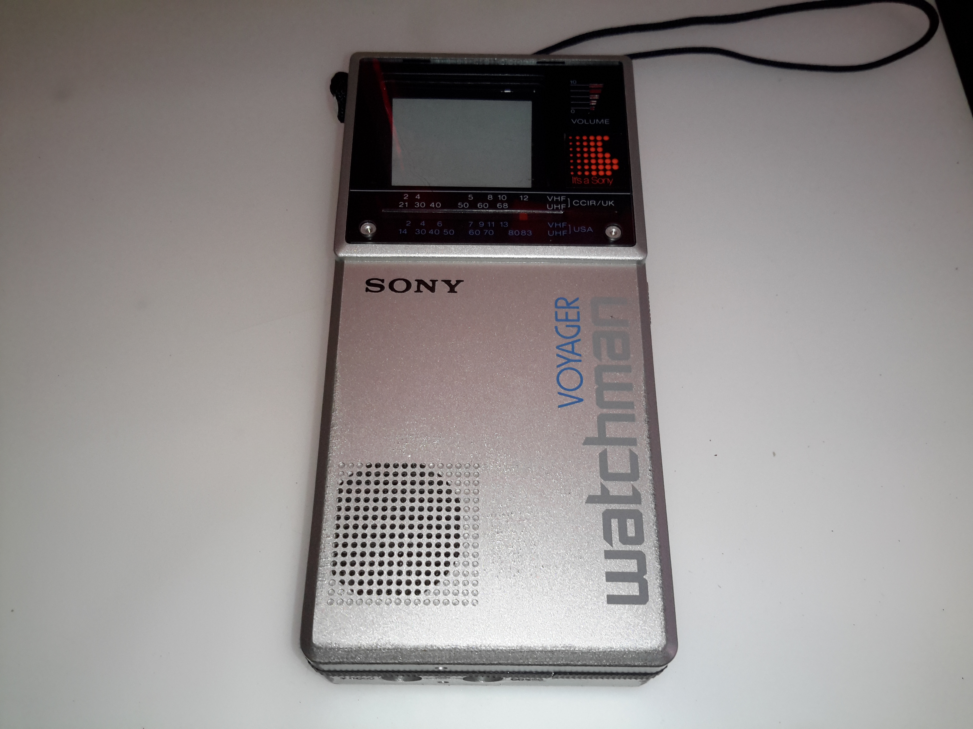
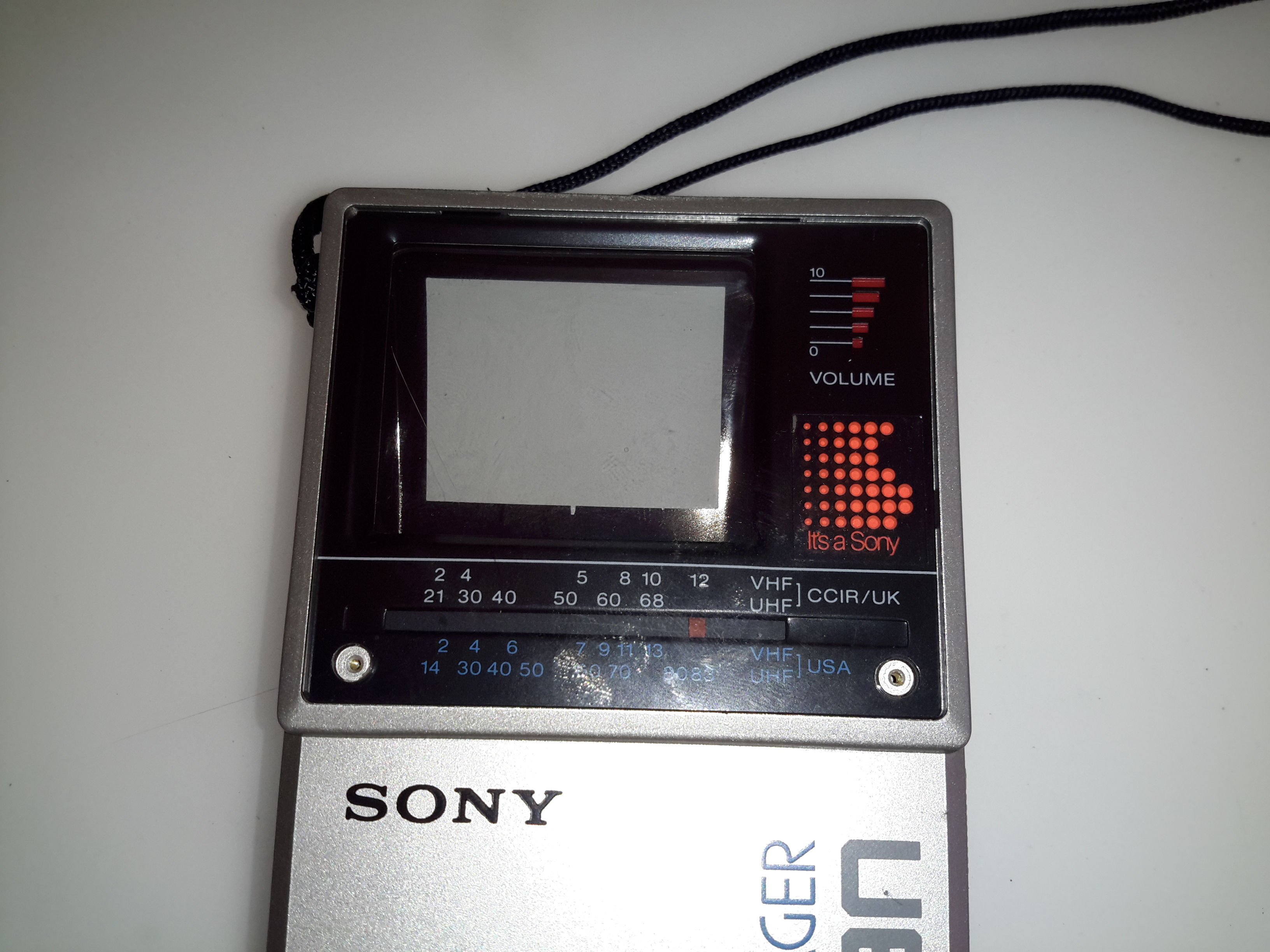
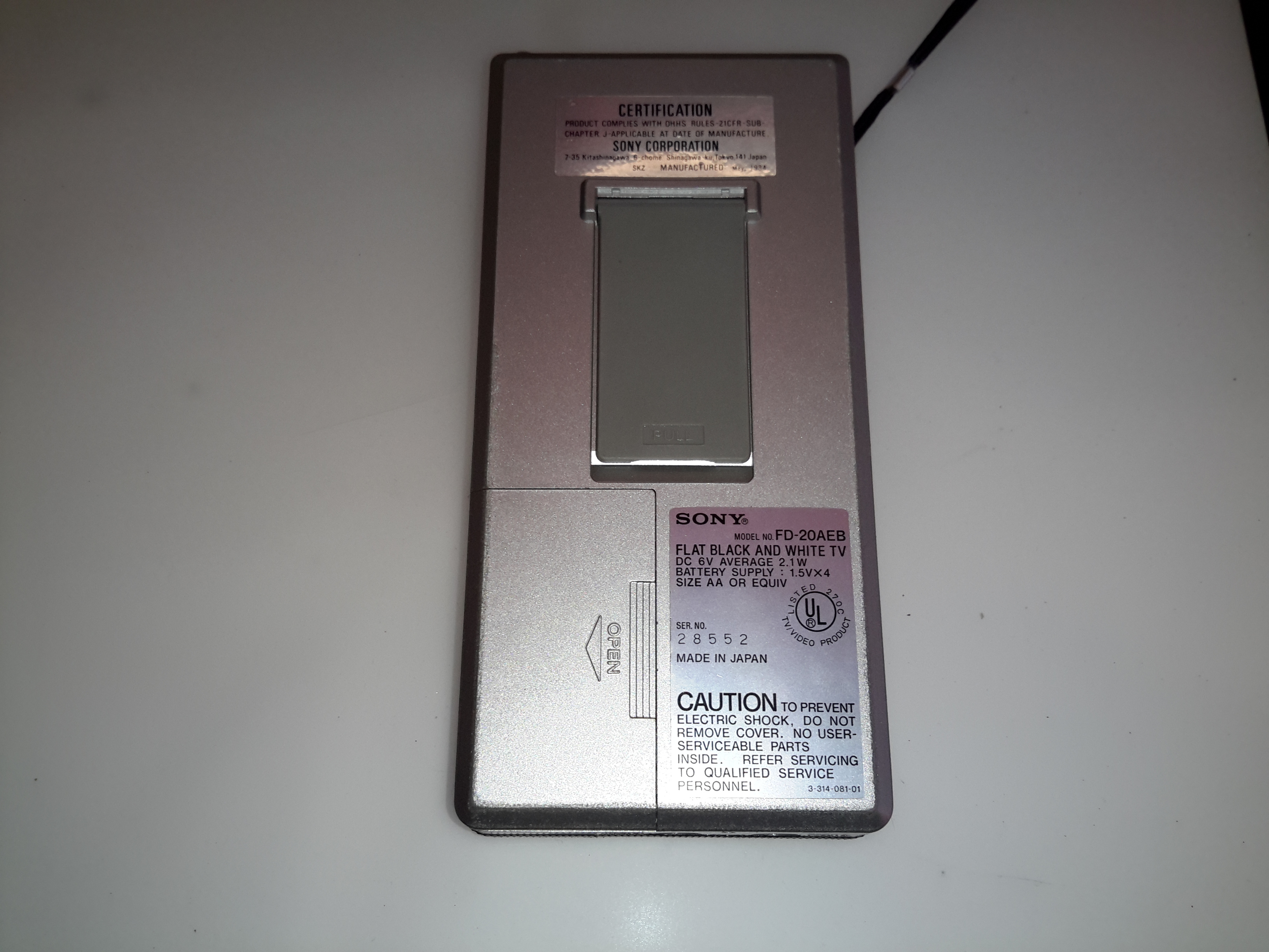
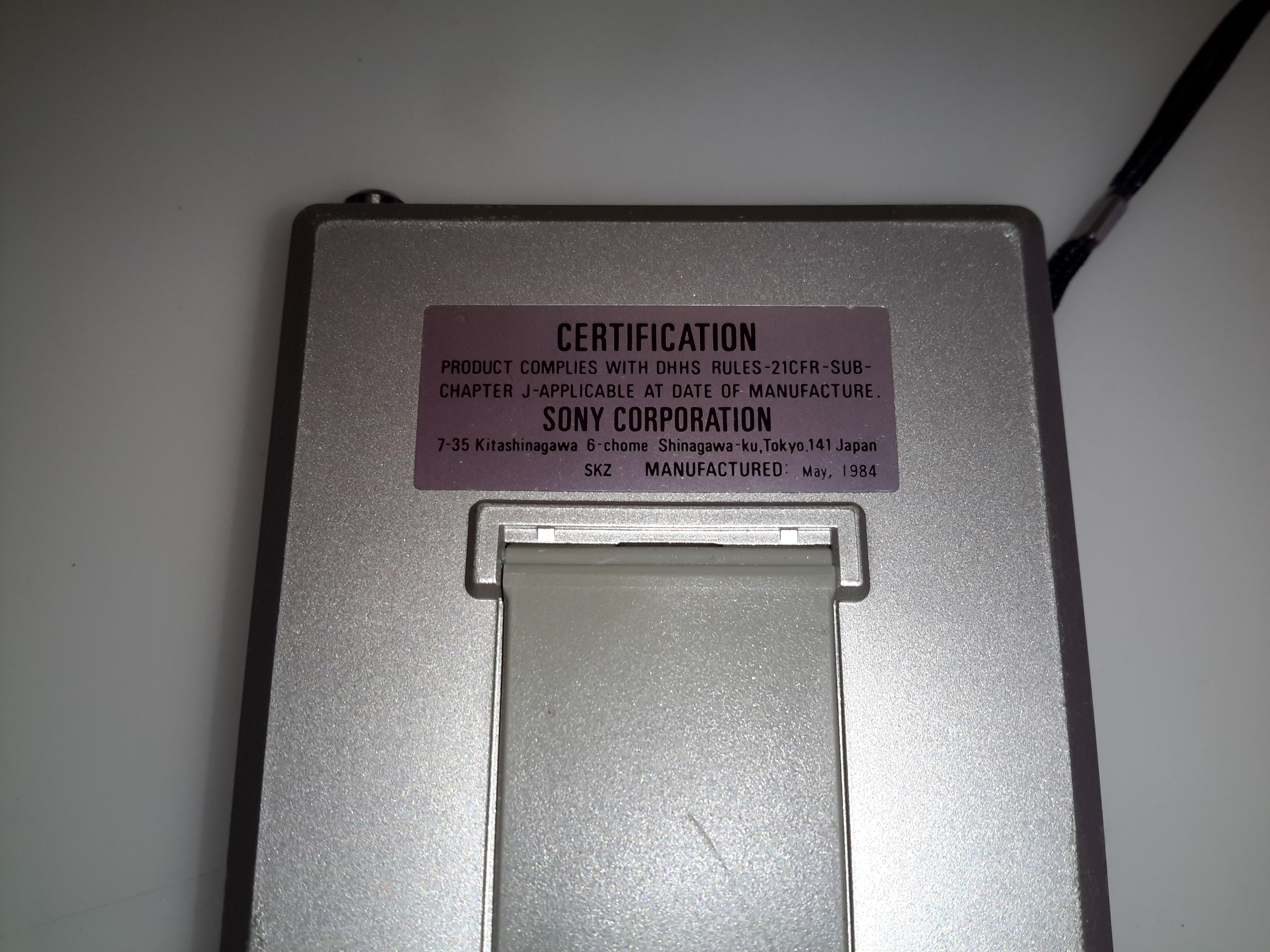
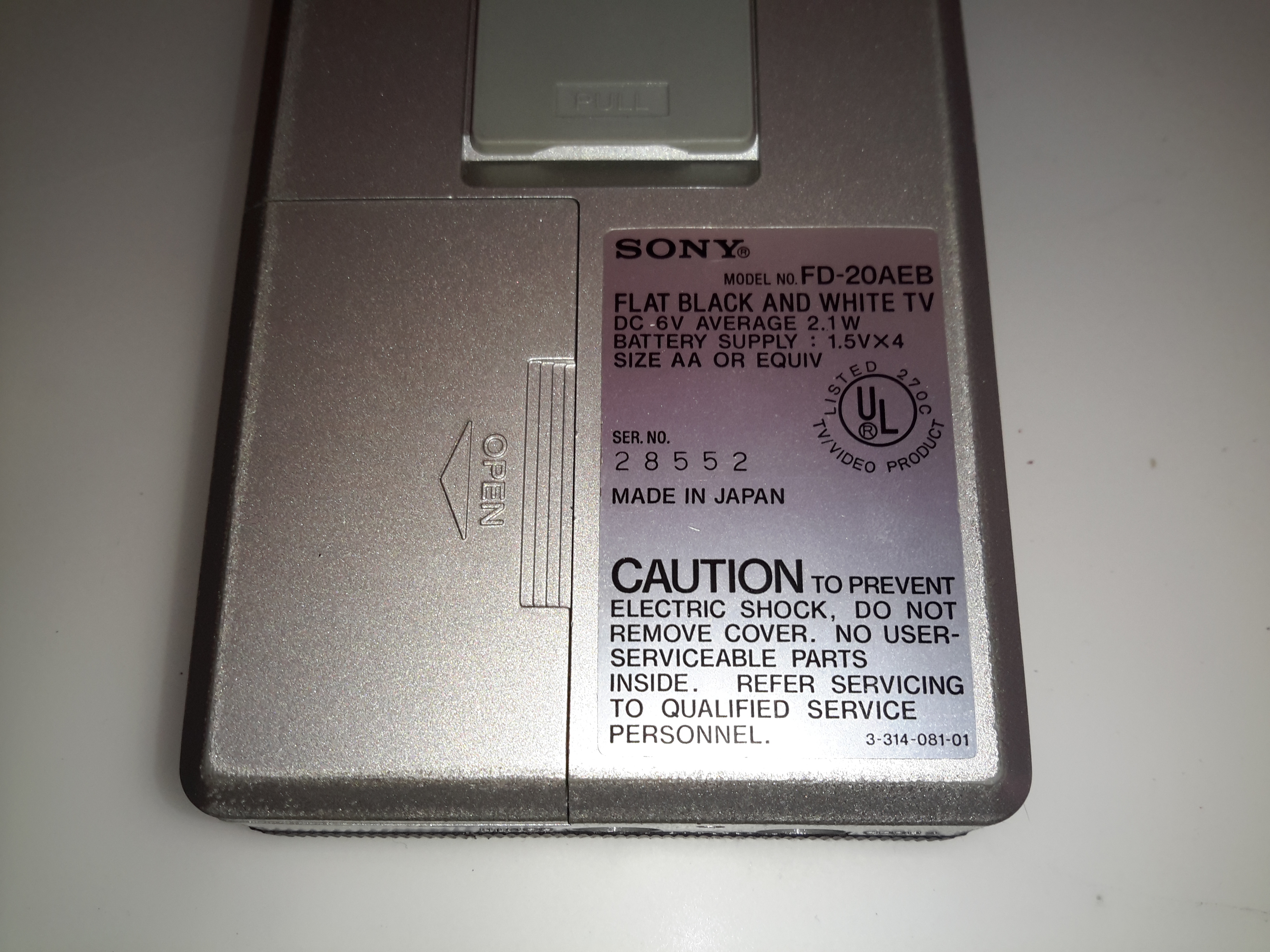
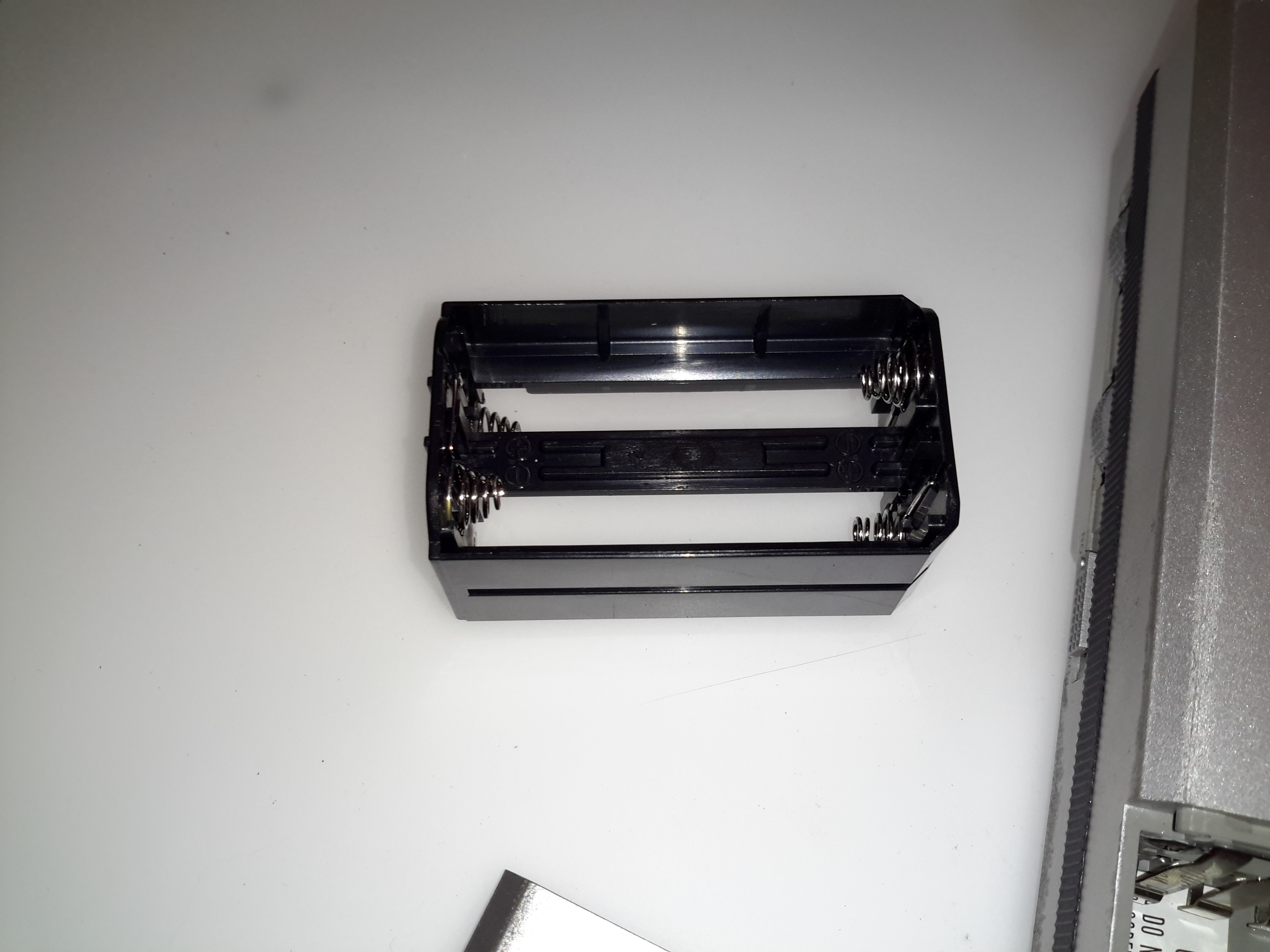
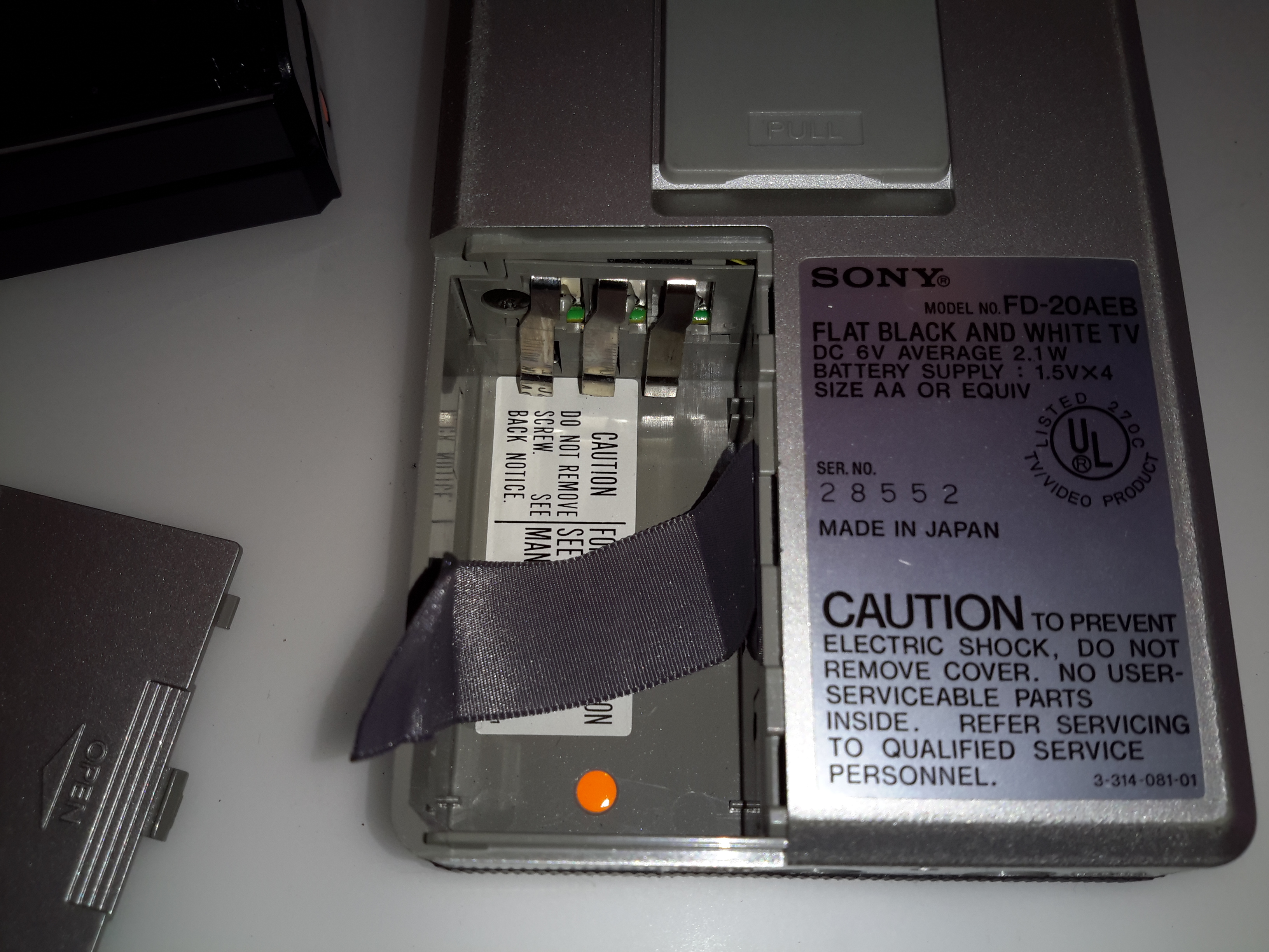
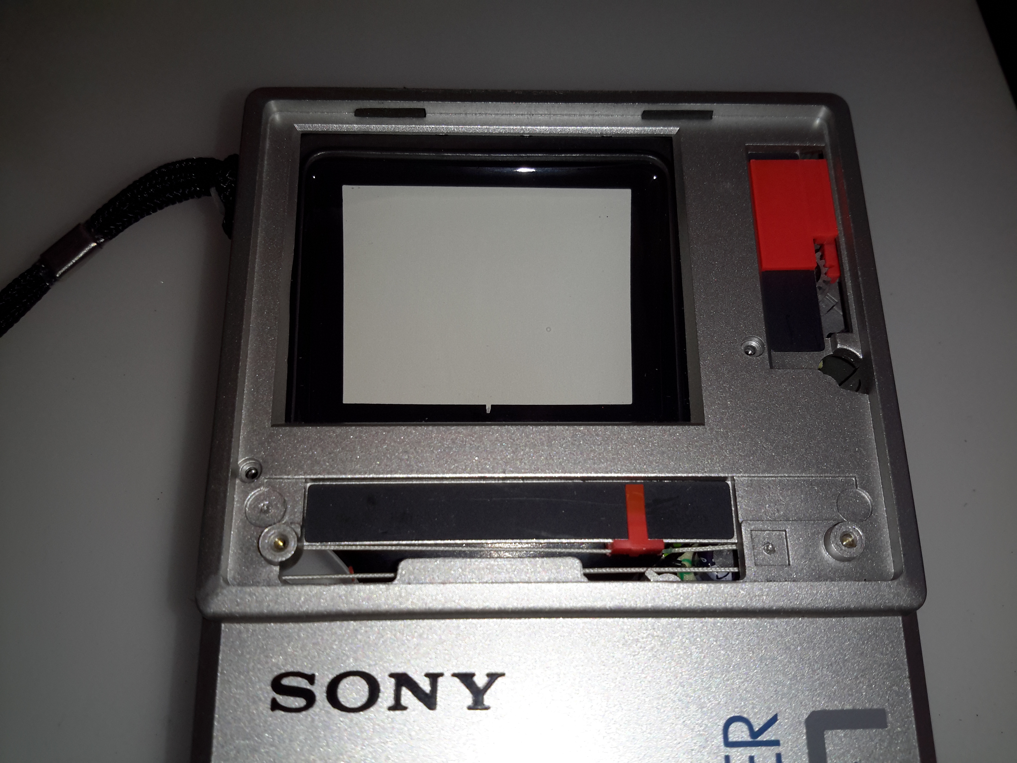
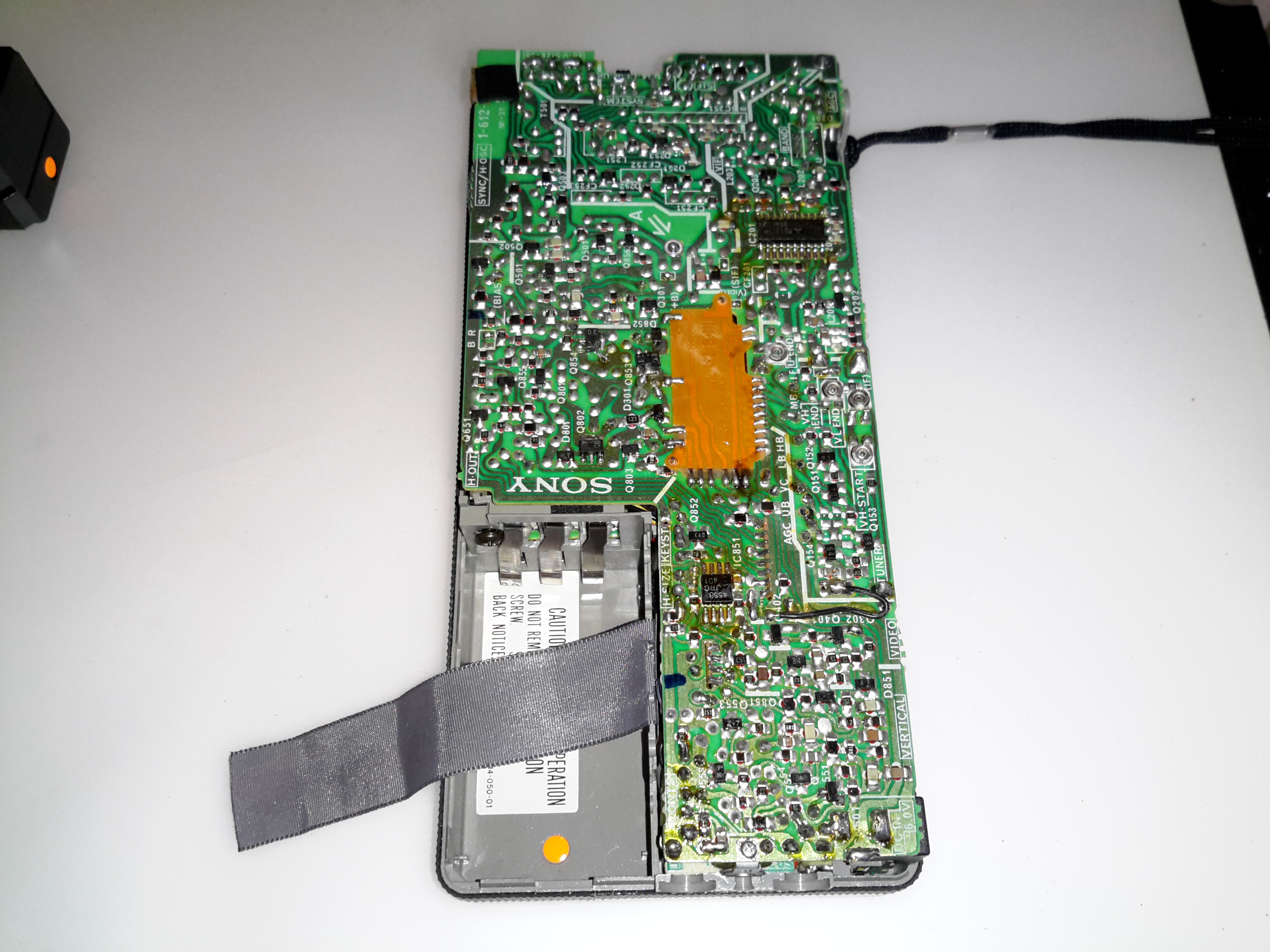
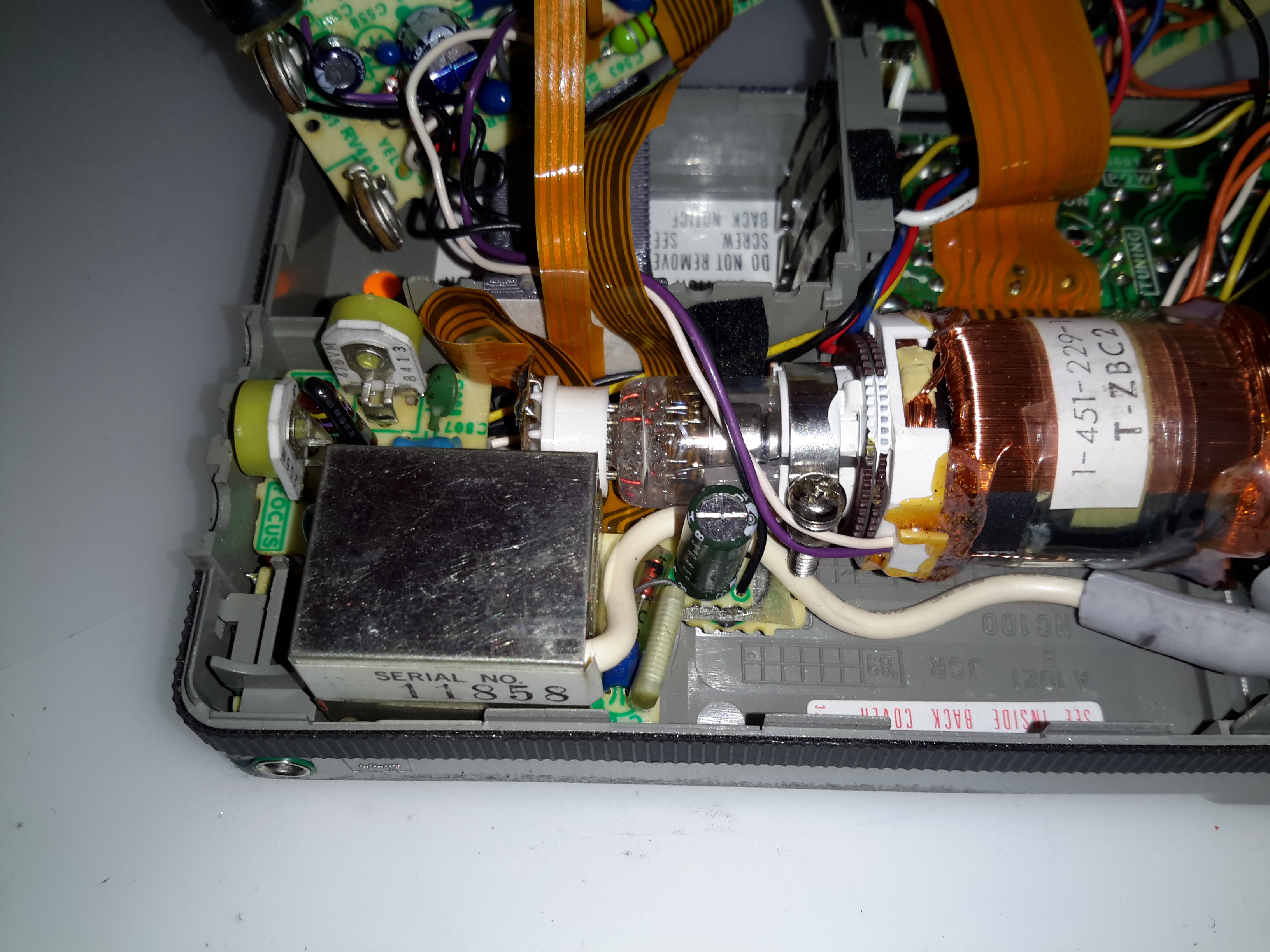
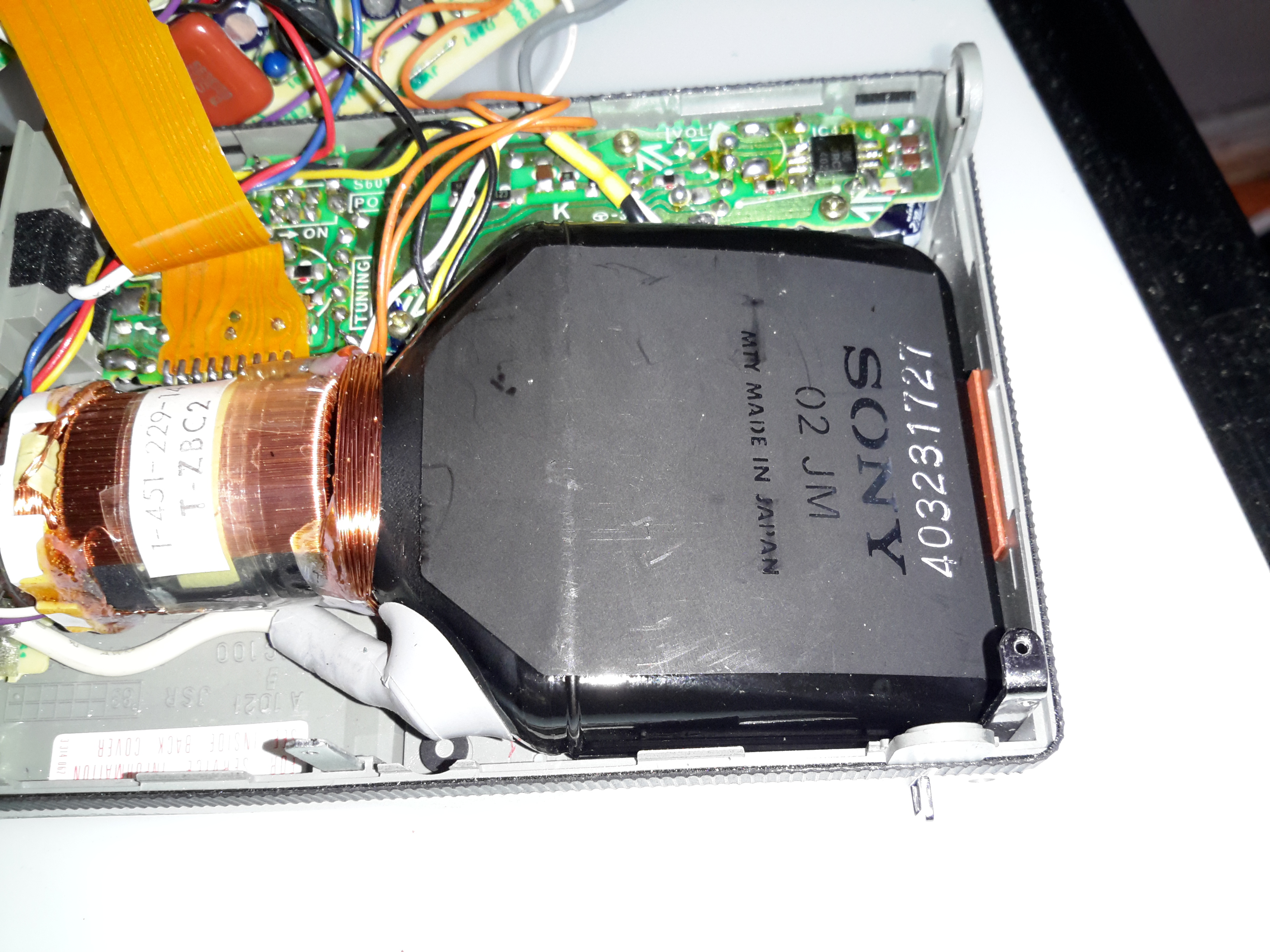
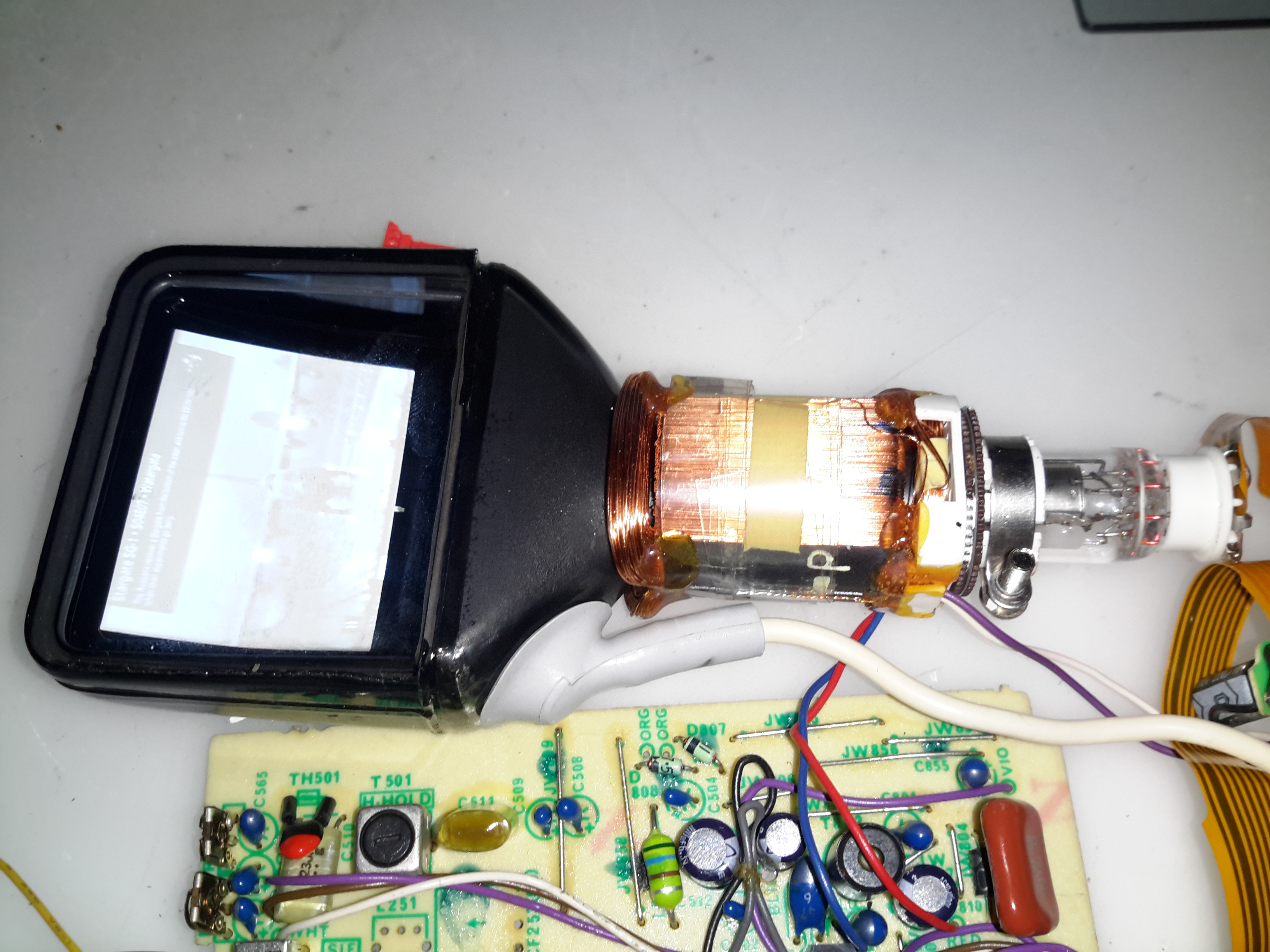
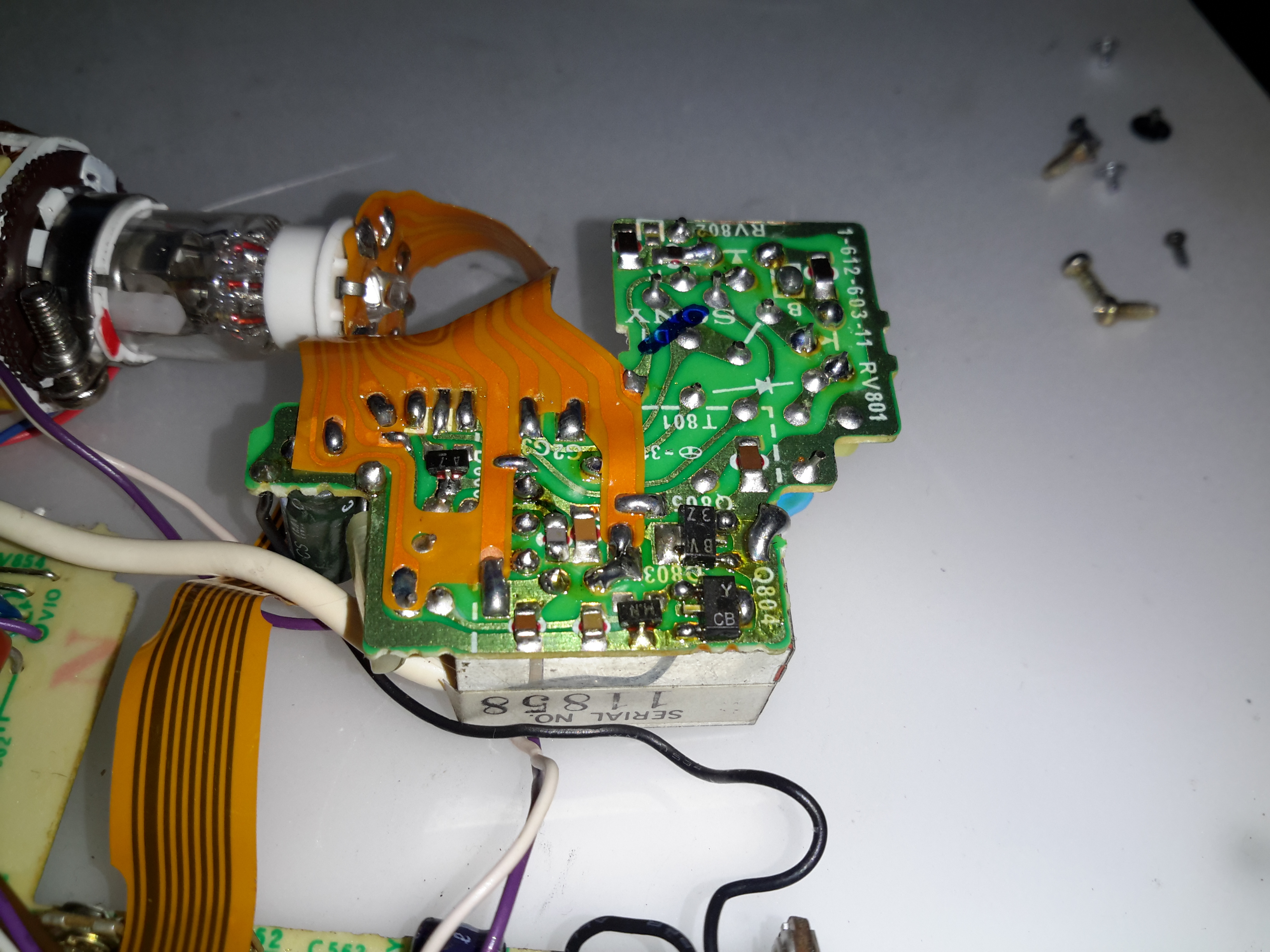
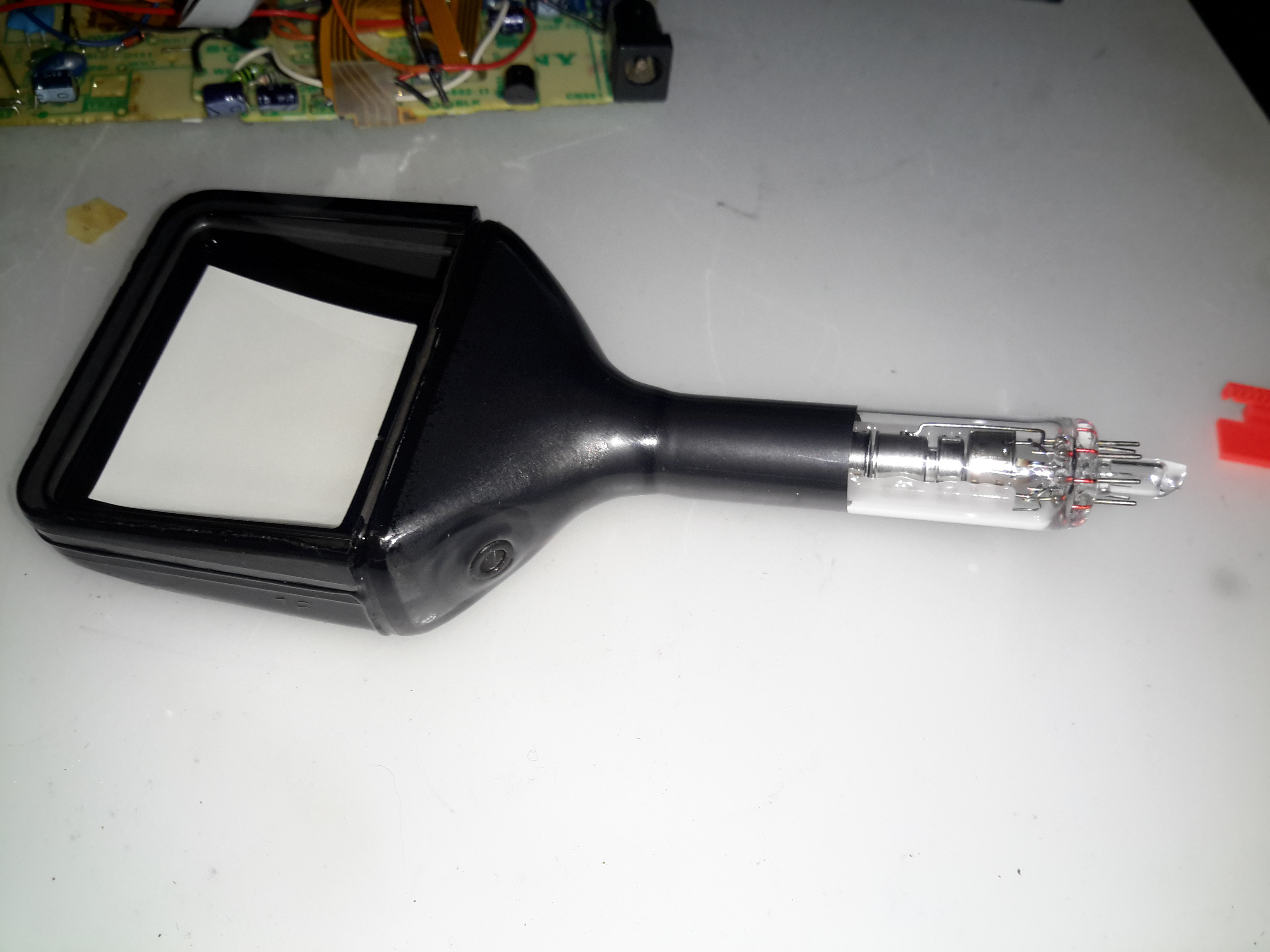
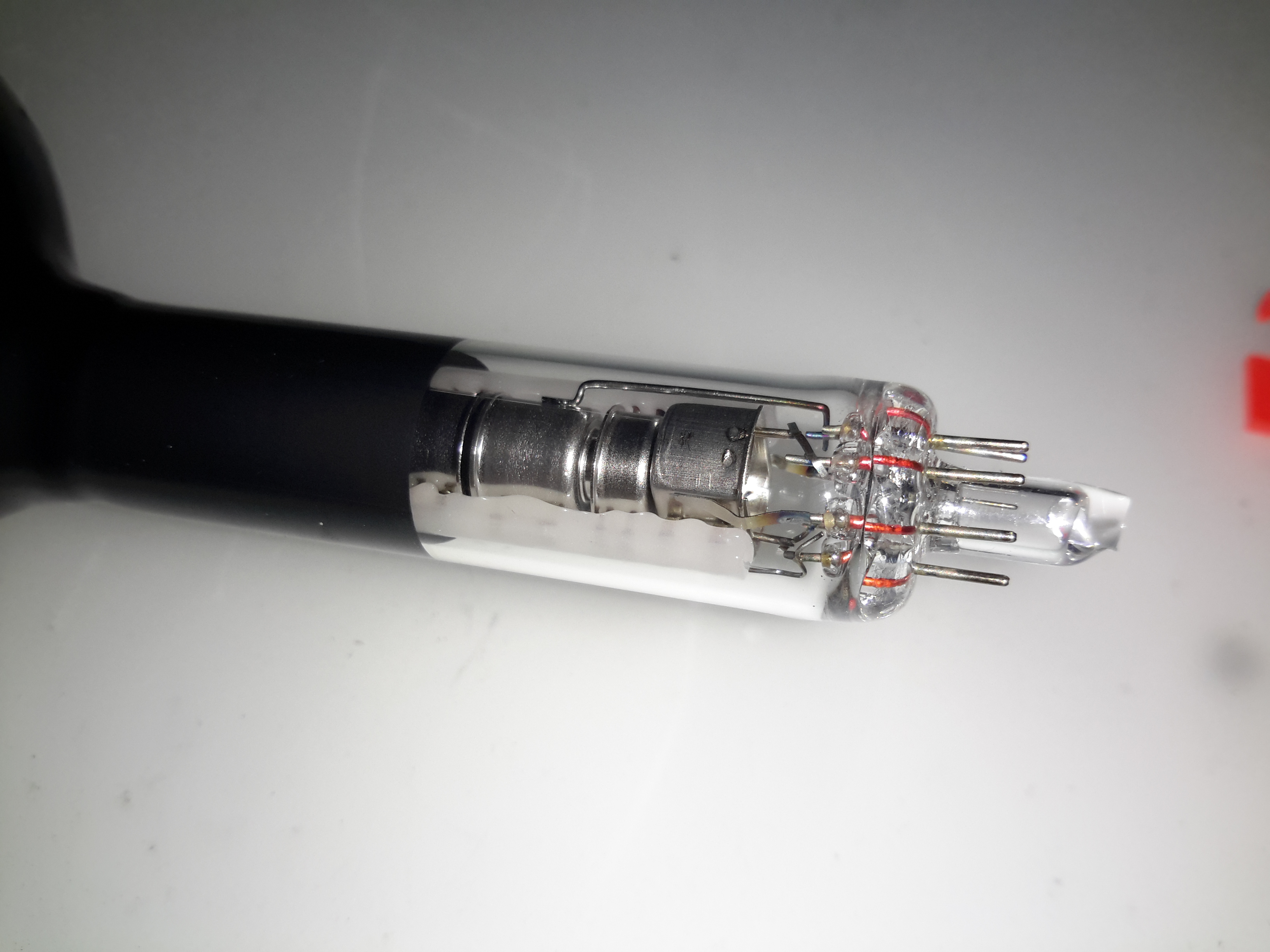
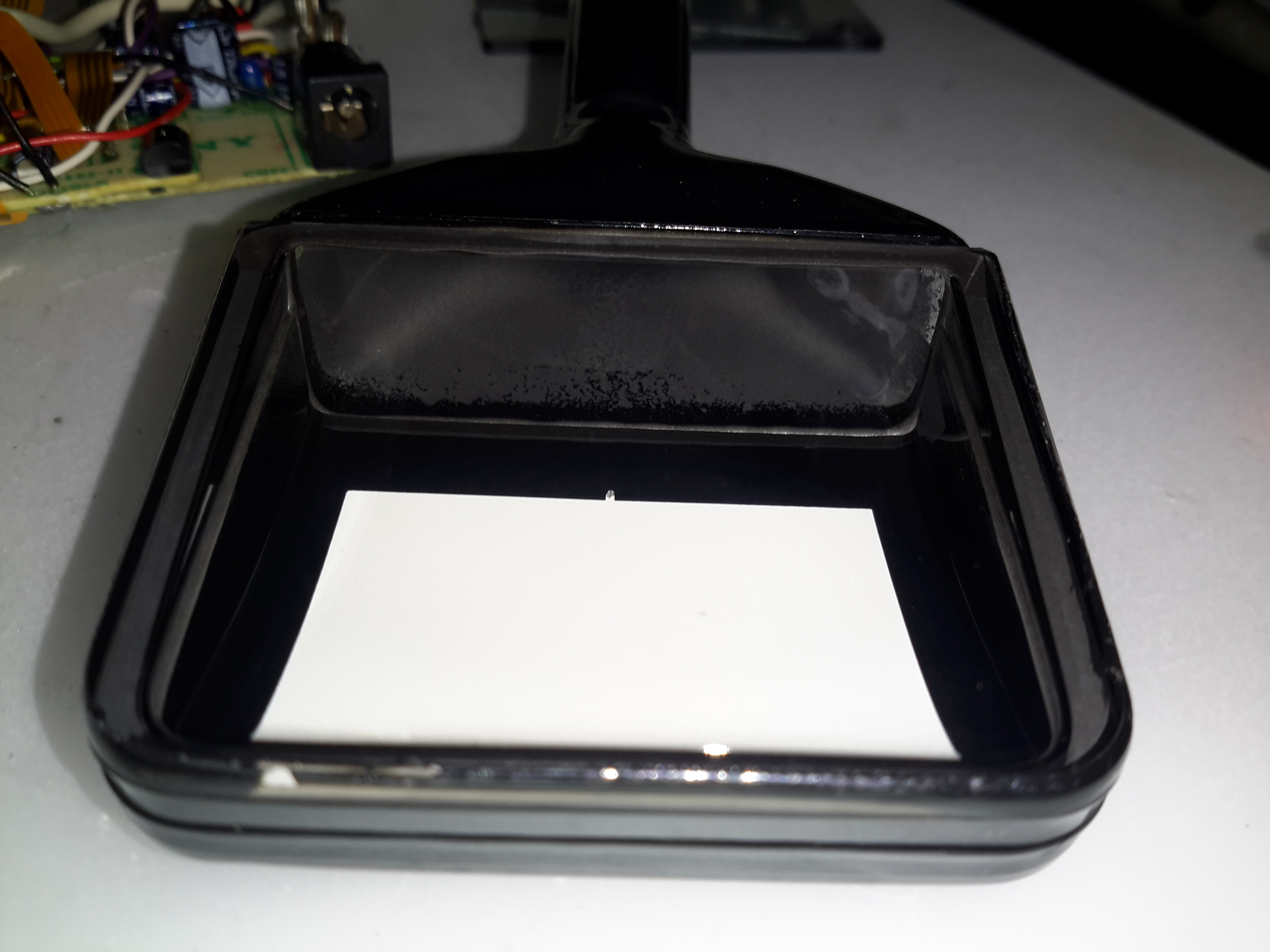

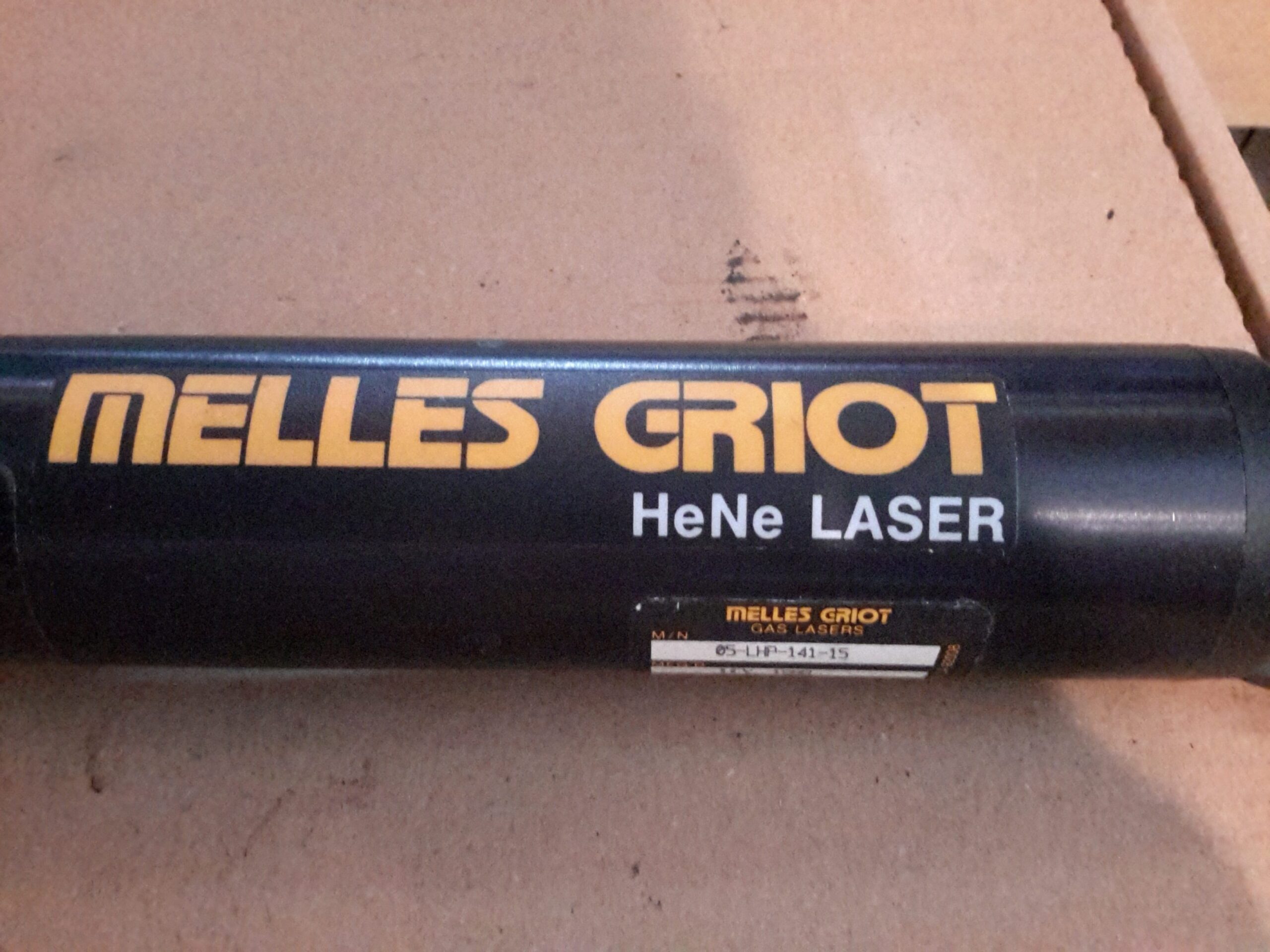
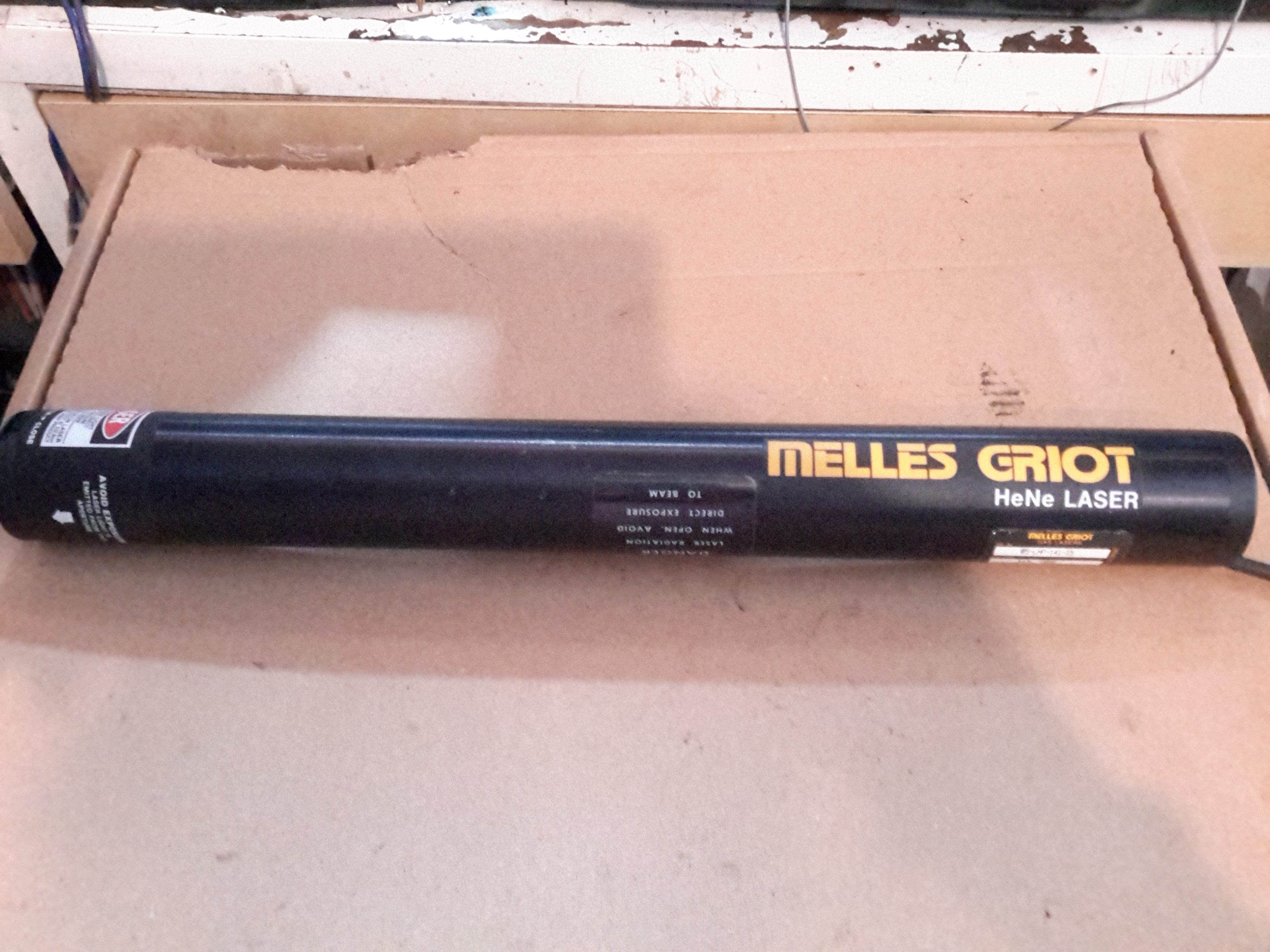
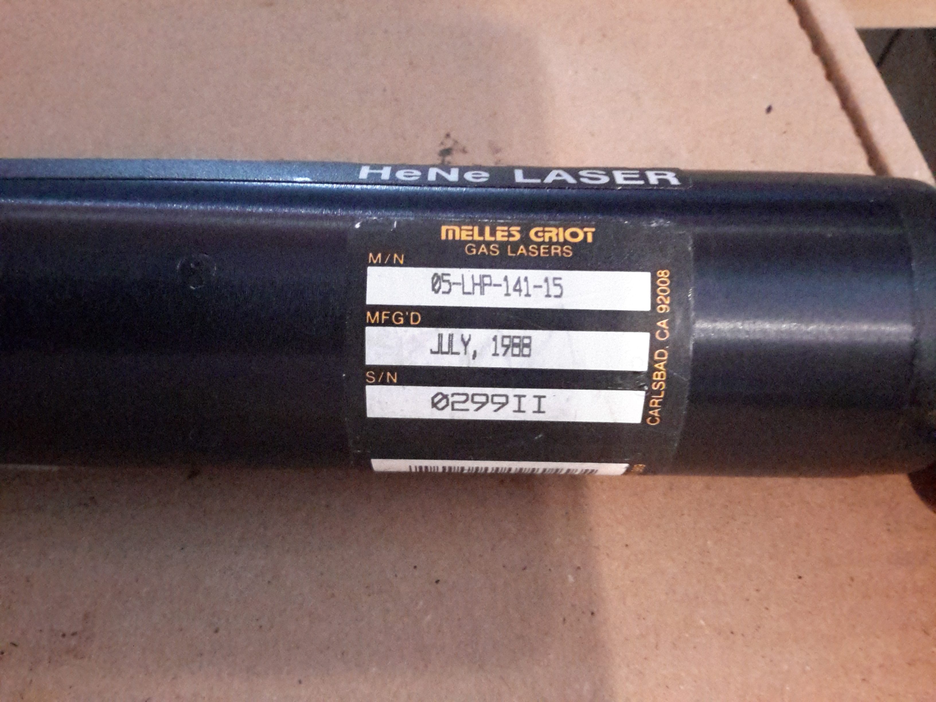
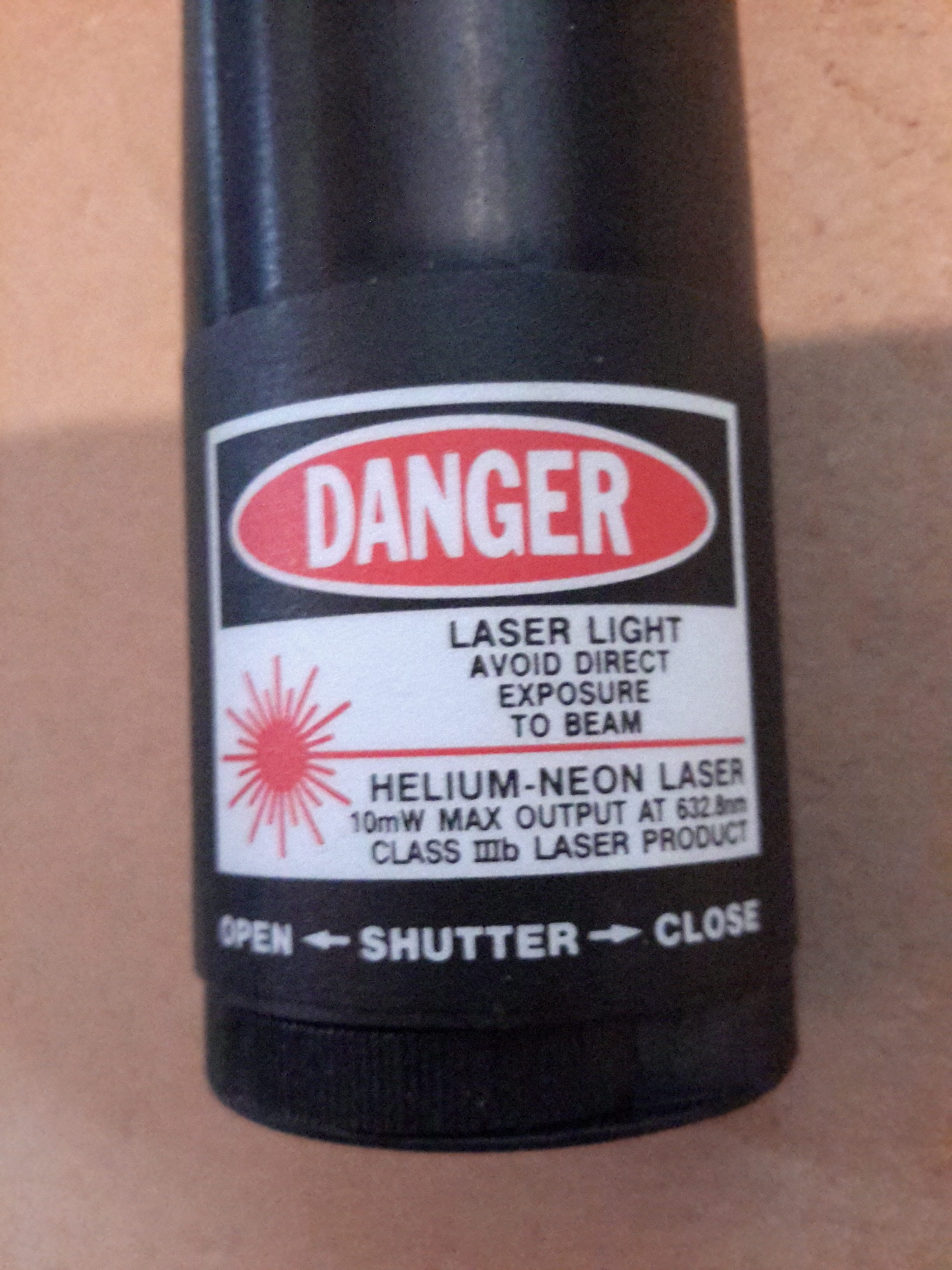
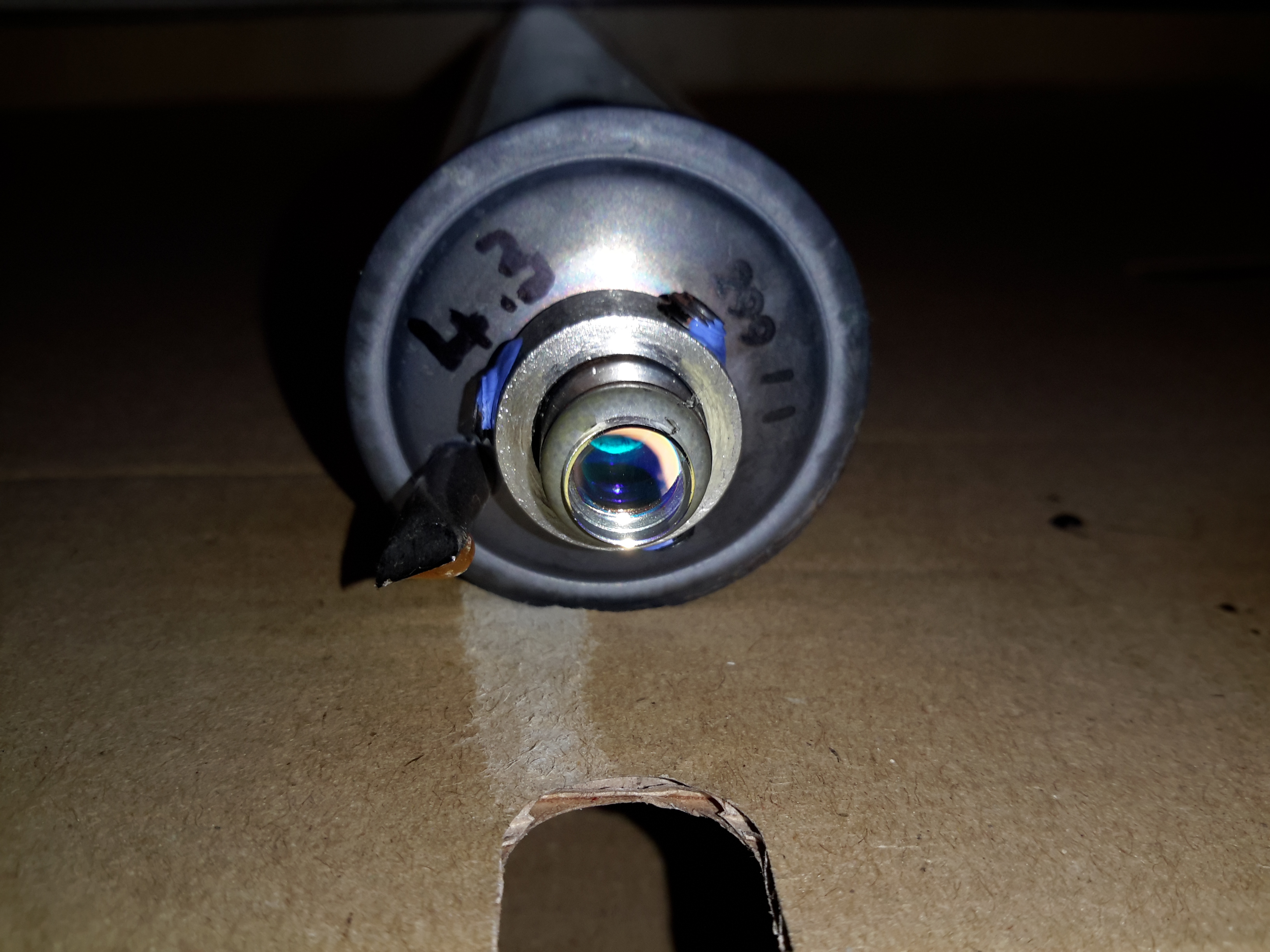
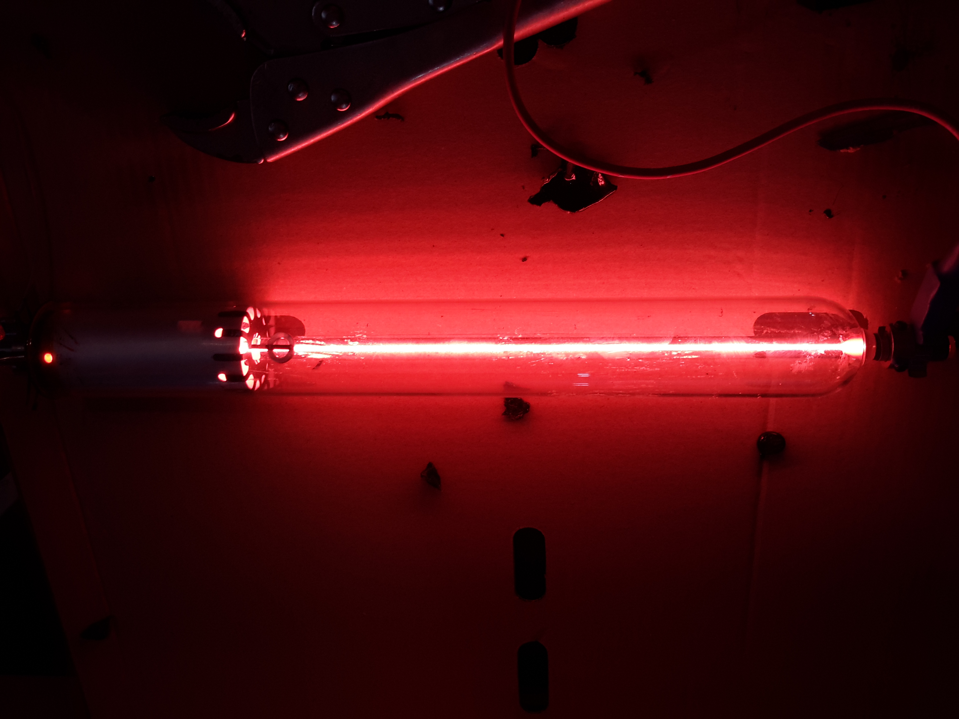
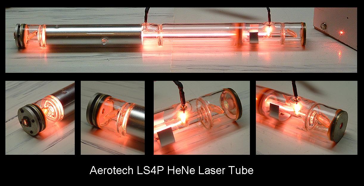
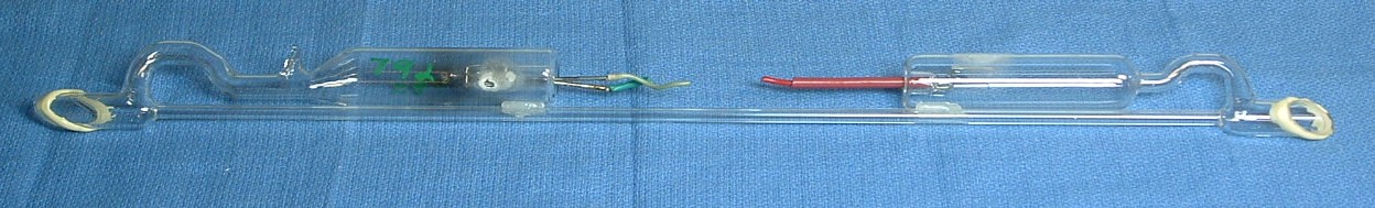
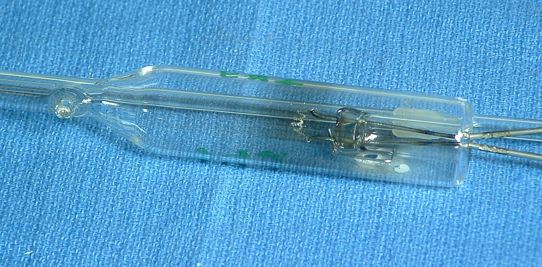
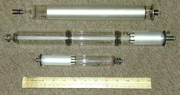
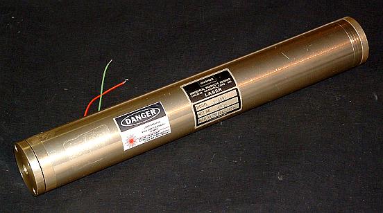
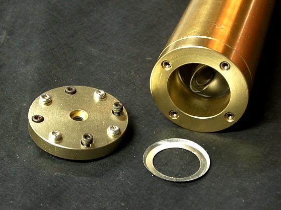
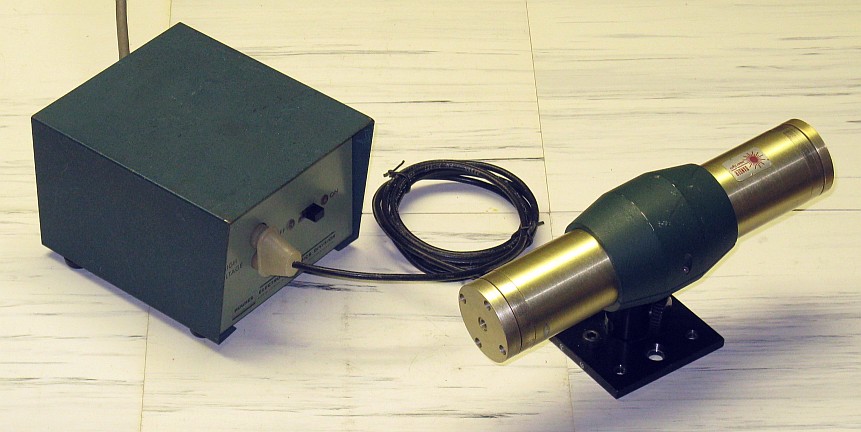
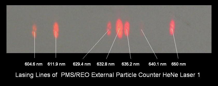
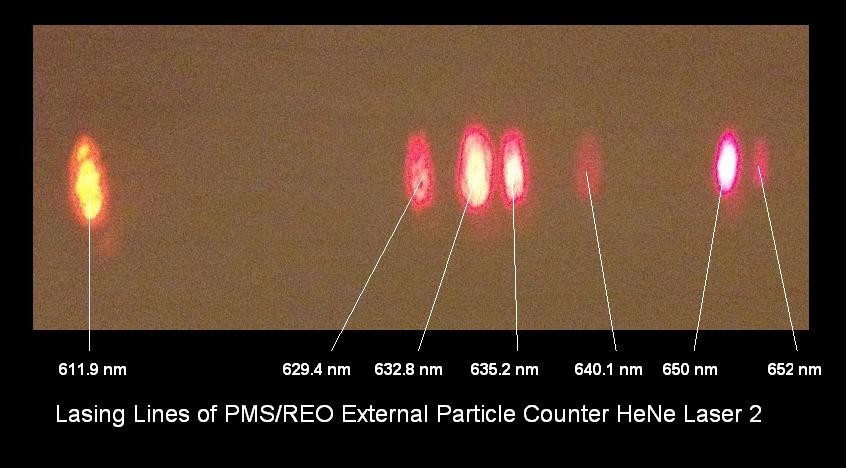
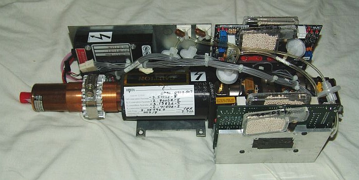
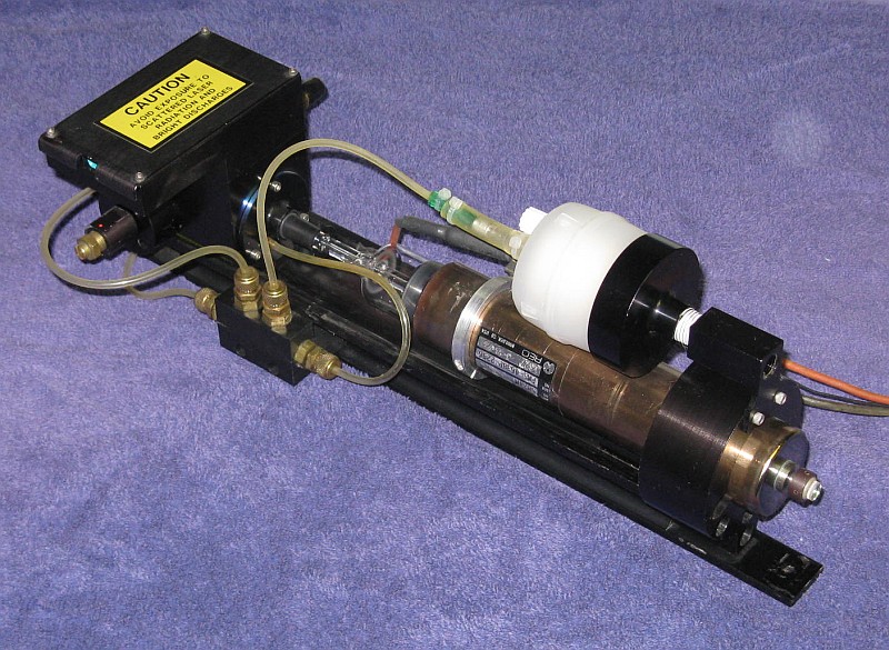
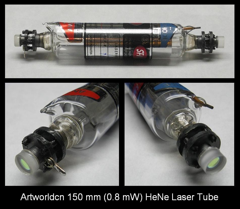
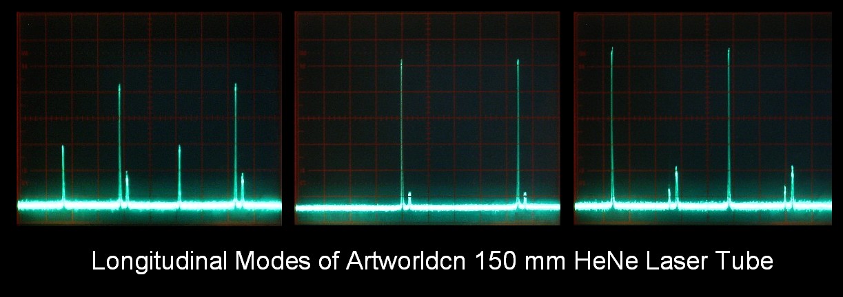
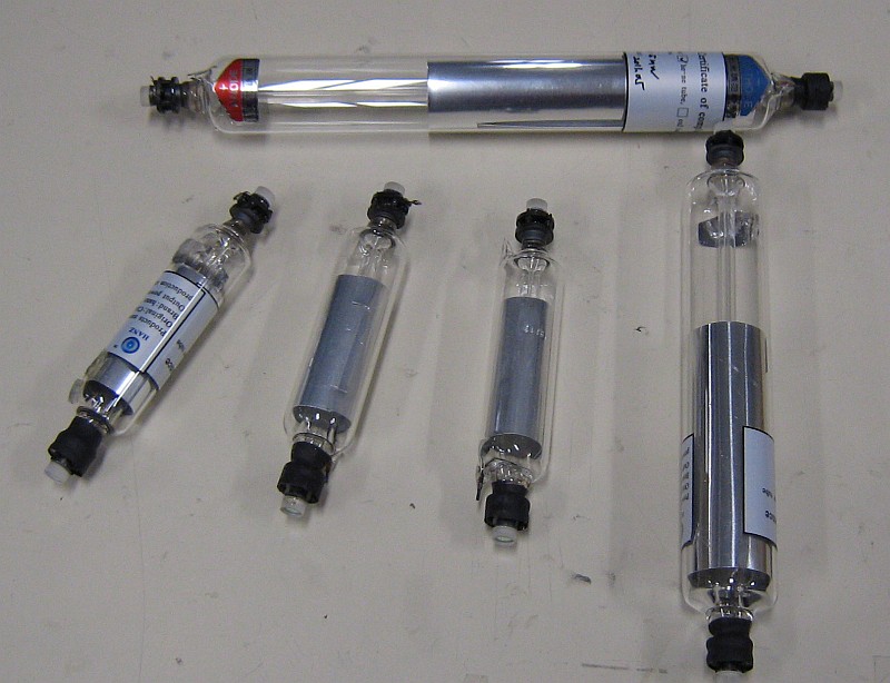
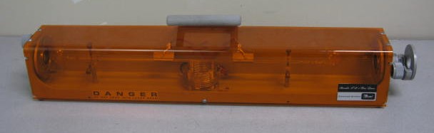
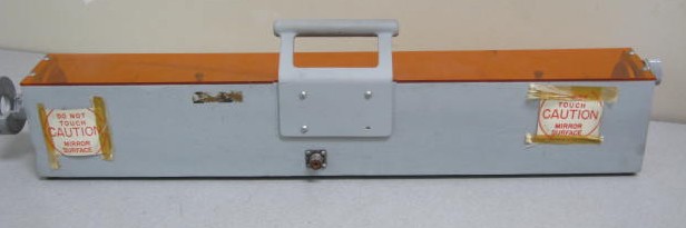

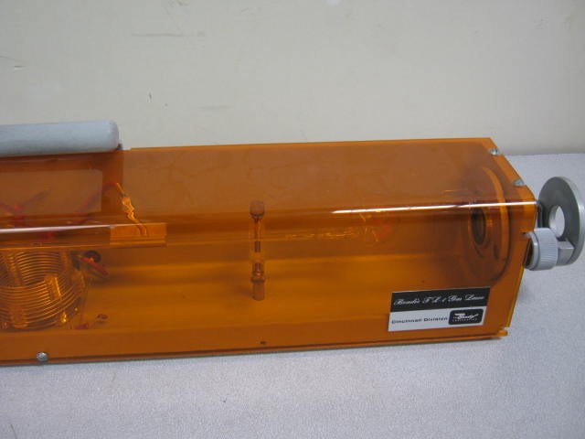
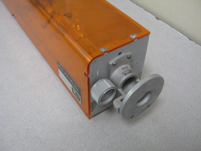
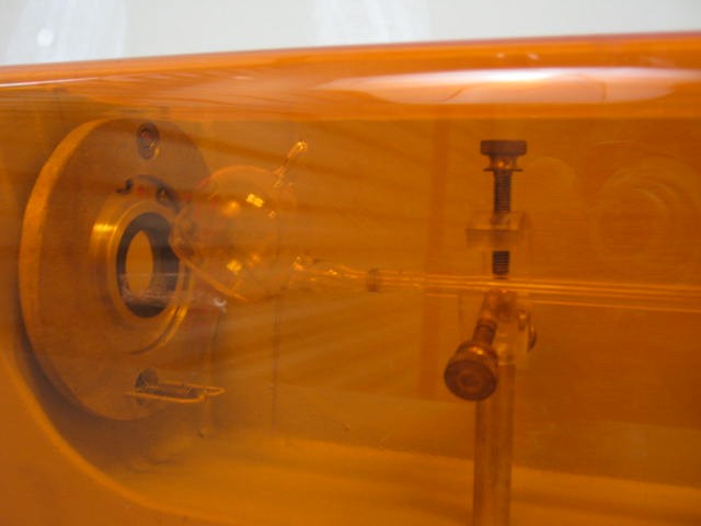
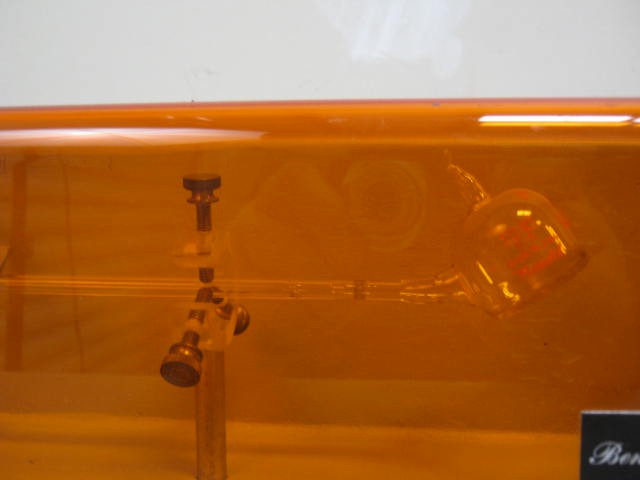
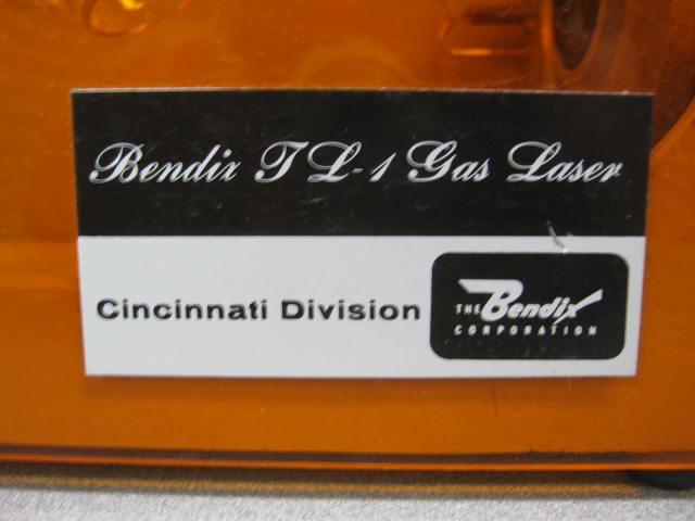
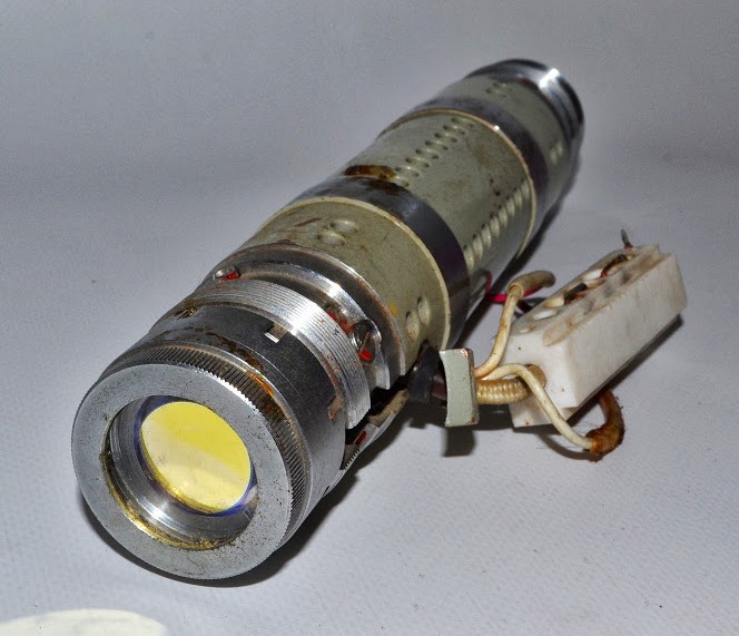
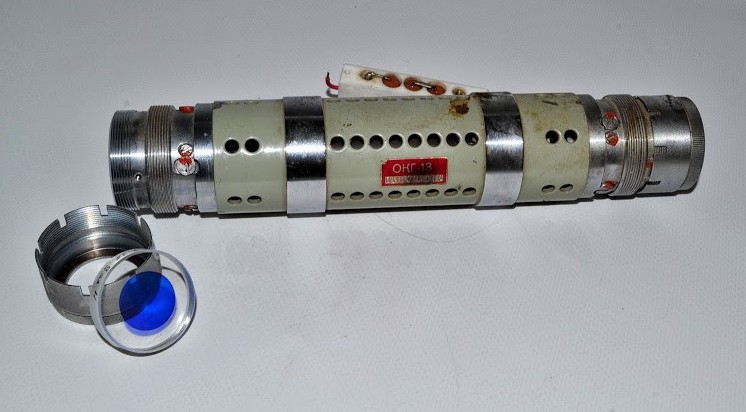
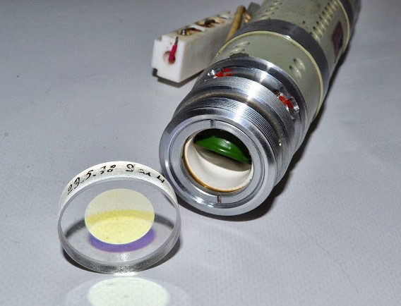
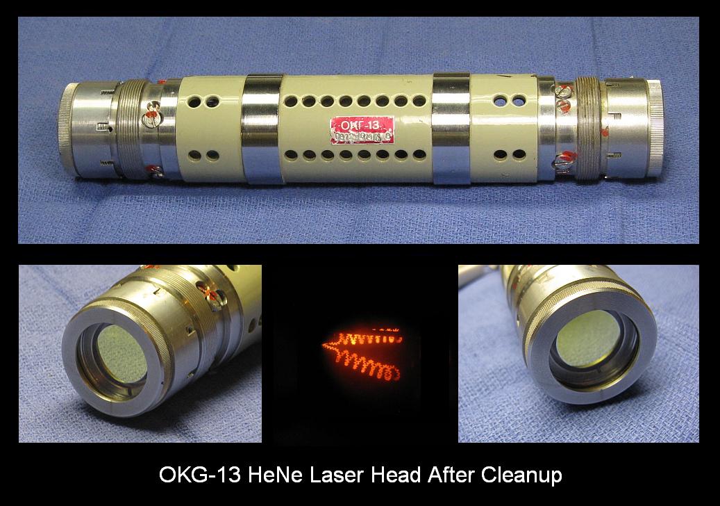
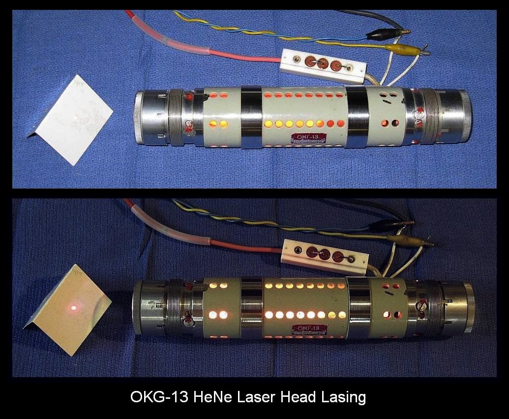
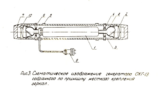
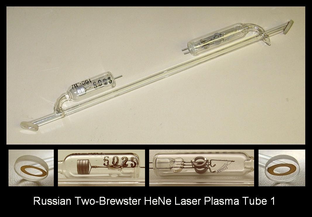
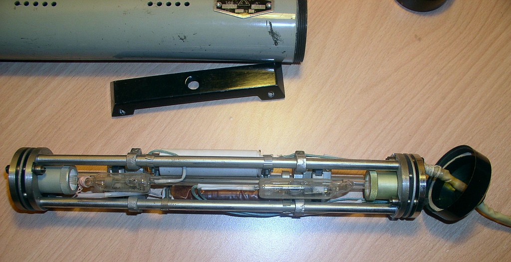
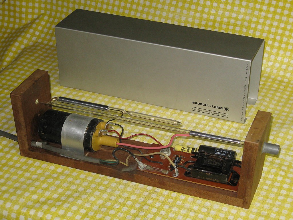
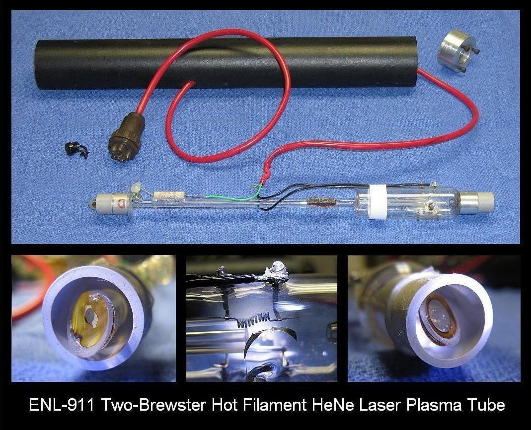
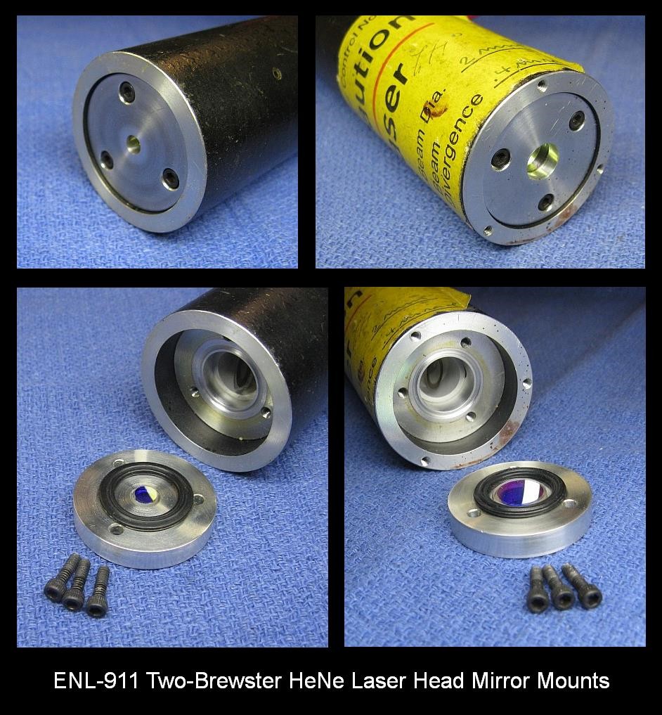
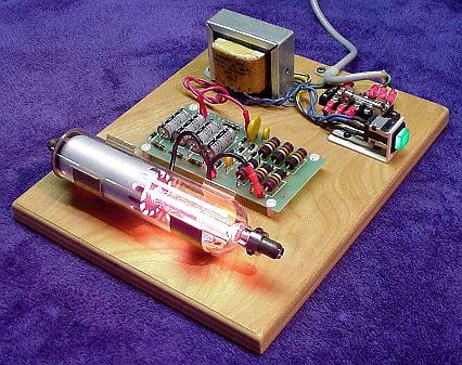

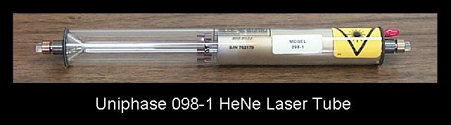
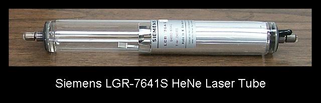
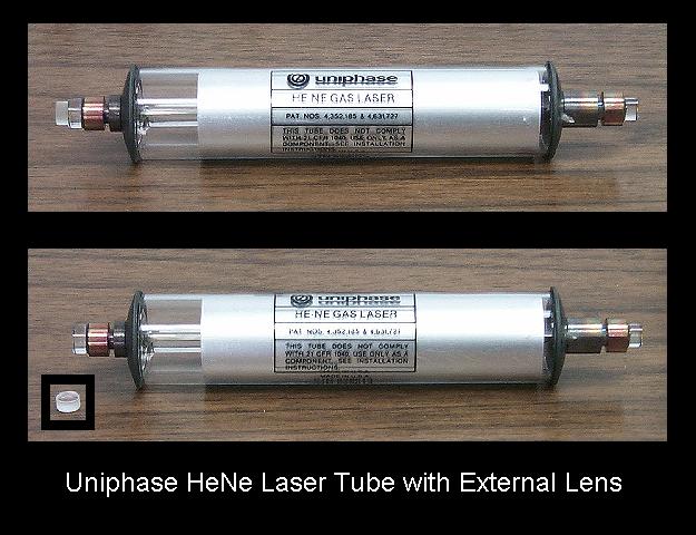
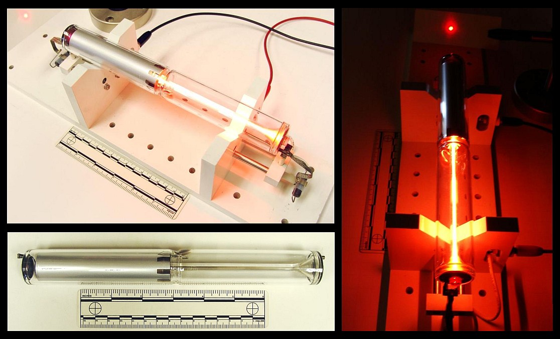
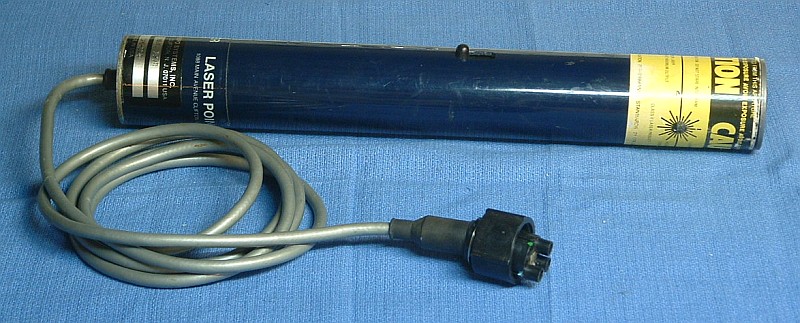
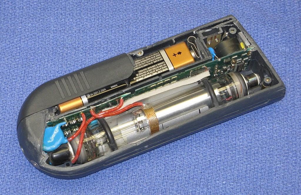
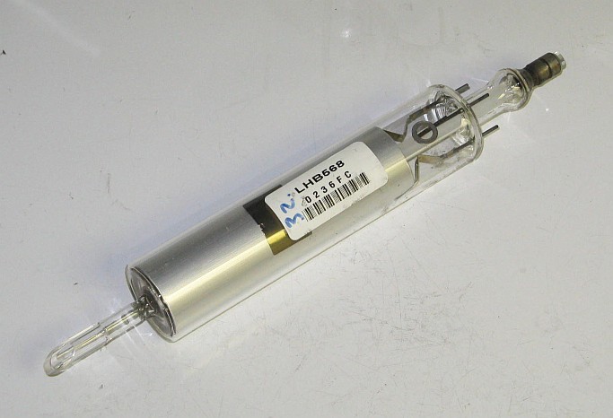
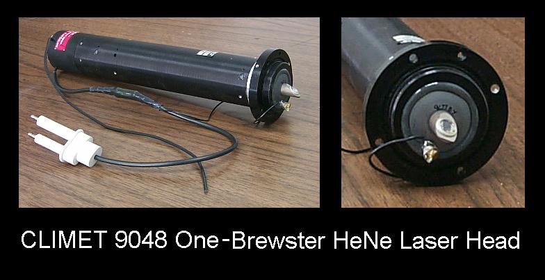
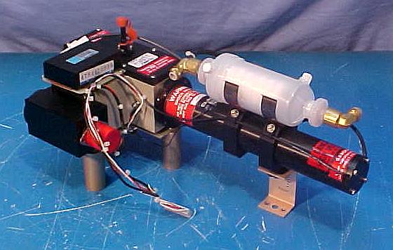
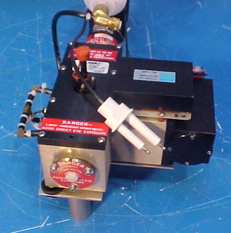
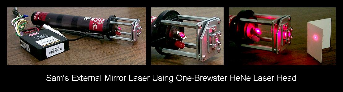
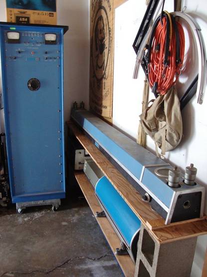


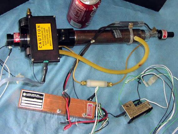