Posted on 5 Comments

Jaguar S-Type Aux Heater / Webasto Thermo Top V Part 1 – Teardown & Cleaning

Jag Label
Jag Label

Here’s another Diesel-fired heater related project – these Webasto heaters are fitted to Jaguar S-Type cars as auxiliary heaters, since (according to the Jag manual), the modern fuel-efficient diesels produce so little waste heat that extra help is required to run the car’s climate control system. (Although this seems to nullify any fuel efficiency boost, as the fuel saved by not producing so much waste heat in the engine itself is burned in an aux heater to provide heat anyway). The unfortunate part is these units don’t respond to applying +12v to Pin 1 of the ECU to get them to start – they are programmed to respond to CAN Bus & K-Line Bus only, so they require a bit more effort to get going. They also don’t have a built-in water circulation pump unlike the Webasto Thermo Top C heaters – they expect the water flow to be taken care of by the engine’s coolant pump.
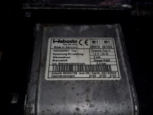
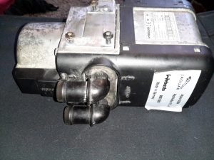
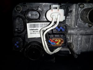
Webasto Label
Webasto Label
Water Side
Water Side

The water ports are on the side of this heater instead of the end, the heat exhanger is on the left. These hearers are fitted to the car under the left front wing, behind a splash guard. Pretty easy to get to but they get exposed to all the road dirt, water & salt so corrosion is a little problem. The fuel dosing pump is in a much more difficult spot to get at – it’s under the car next to the fuel tank on the right hand side. Access to the underside with stands is required to get at this.
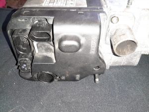
ECU Side
ECU Side

The ECU side has all the other connections – Combustion air, exhaust, fuel, power & control.
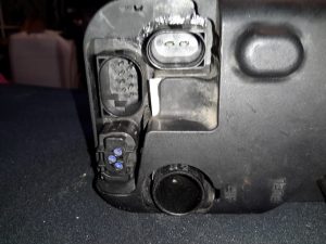
External Connectors
External Connectors

Only two of the external connectors are used on these heaters, the large two pin one is for main power – heavy cable required here as the current draw can climb to ~30A on startup while the glow plug fires. The 8-pin connector on the left is the control connector, where the CAN / K-Line / W-Bus buses live. The fuel dosing pump is also supplied from a pin on this connector. The small 3-pin under that is a blank for a circulation pump where fitted. Pinouts are here:

PinSignal
1Battery Positive
2Battery Negative
Pin NumberSignalNotes
1Telestart / Heater EnableWould usually start the heater with a simple +12v ON signal, but is disabled in these heaters.
2W-Bus / K-LineDiagnostic Serial Bus Or Webasto Type 1533 Programmer / Clock
3External Temp Sensor
4CAN-CAN Bus Low
5Fuel Dosing PumpFuel Pump output. Connect pump to this pin & ground. Polarity unimportant.
6Solenoid ValveFuel cutoff solenoid optionally fitted here.
7CAN+CAN Bus High
8Cabin Heater Fan ControlThis output switches on when heater reaches +50°C to control car heater blower
PinSignalNotes
1??
2Circulation Pump +
3Circulation Pump -
ECU Cover Removed
ECU Cover Removed

Removing the clipped-on plastic cover reveals the other ECU connectors. The large white one feeds the glow plug, & the large multi-pin below brings in the temp & overheat sensor signals.
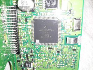
MC9S12DT128B Microcontroller

The heart of the ECU is a massive microcontroller, a Freescale MC9S12DT128B, attached to a daughterboard hooked into the ECU power board.
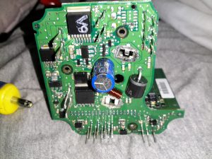
Power Section
Power Section

The high power section is on the board just under the connectors, here all the large semiconductors live for switching the fan motor, glow plug, external loads, etc.
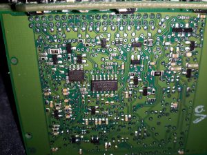
LIN & CAN Bus Transceivers

The bus transceivers are separate ICs on the control board, a TJA1041 takes care of the CAN bus. There’s also a TJA1020 LIN bus transceiver here, which is confusing since none of the Webasto documentation mentions LIN bus control.
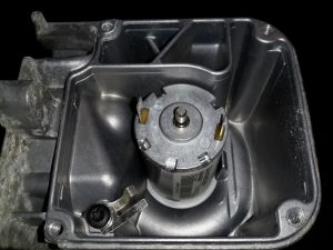
Combustion Fan Motor

The combustion fan motor is in the ECU compartment, nicely sealed away from the elements. There is no speed sensor on these blowers, unlike the Eberspacher ones.
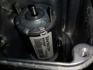
Motor Details
Motor Details

The motor is a Buhler, rated at 10.5v.
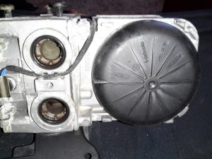
Water Ports & Combustion Fan Cover

Unclipping the cover from the other end reveals the combustion fan, it’s under the black cover. (These are side-channel blowers, to provide the relatively high static pressure required to run the burner).
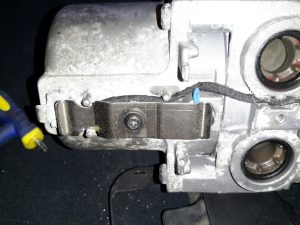
Sensor Clip
Sensor Clip

The overheat & temperature sensors are on the end of the heat exchanger, retained by a stainless clip.
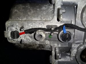
Temp & Overheat Sensors

With the clip removed, the sensors can be seen better. There’s some pretty bad corrosion of the aluminium alloy on the end sensor, it’s seized in place.
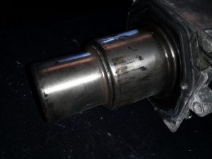
Burner
Burner

The heater splits in half to reveal the evaporative burner itself. I’ve already cleaned the black crud off with a wire brush here, doesn’t look like this heater has seen much use as it’s pretty clean inside.
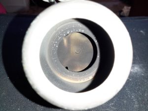
Burner Chamber
Burner Chamber

Inside the burner the fuel evaporates & is ignited. There is a brass mesh behind the backplate of the burner to assist with vaporisation.
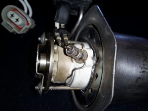
Glow Plug
Glow Plug

The glow plug is fitted into the side of the burner ceramic here. This is probably a Silicon Carbide device. It also acts as a flame sensor when the heater has fired up. The fuel inlet line is to the left under the clamp.
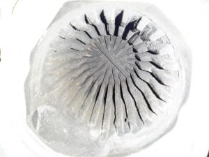
Heat Exhanger
Heat Exhanger

The hot gases from the burner flow into the heat exchanger here, with many fins to increase the surface area. There’s only a couple of mm coating of carbon here, after 10 years on the car I would have expected it to be much more clogged.

I’m currently waiting on some components to build an interface so I can get the Webasto Thermo Test software to talk to the heater. Once this is done I can see if there are any faults logged that need sorting before I can get this heater running, but from the current state it seems to be pretty good visually. More to come once parts arrive!

The full service manual for these heaters can be grabbed from here, along with the wiring details for the Jaguar implementation & the Thermo Test software for talking to them:

[download id=”5618″]

[download id=”5620″]

[download id=”5622″]
Posted on Leave a comment

nb Tanya Louise Heating System – Oxide Sludge

I wrote a few weeks ago about replacing the hot water circulating pump on the boat with a new one, and mentioned that we’d been through several pumps over the years. After every replacement, autopsy of the pump has revealed the failure mode: the first pump failed due to old age & limited life of carbon brushes. The second failed due to thermal shock from an airlock in the system causing the boiler to go a bit nuts through lack of water flow. The ceramic rotor in this one just cracked.
The last pump though, was mechanically worn, the pump bearings nicely polished down just enough to cause the rotor to stick. This is caused by sediment in the system, which comes from corrosion in the various components of the system. Radiators & skin tanks are steel, engine block cast iron, back boiler stainless steel, Webasto heat exchanger aluminium, along with various bits of copper pipe & hose tying the system together.
The use of dissimilar metals in a system is not particularly advisable, but in the case of the boat, it’s unavoidable. The antifreeze in the water does have anti-corrosive additives, but we were still left with the problem of all the various oxides of iron floating around the system acting like an abrasive. To solve this problem without having to go to the trouble of doing a full system flush, we fitted a magnetic filter:

Mag Filter
Mag Filter

This is just an empty container, with a powerful NdFeB magnet inserted into the centre. As the water flows in a spiral around the magnetic core, aided by the offset pipe connections, the magnet pulls all the magnetic oxides out of the water. it’s fitted into the circuit at the last radiator, where it’s accessible for the mandatory maintenance.

Sludge
Sludge

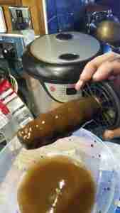
Now the filter has been in about a month, I decided it would be a good time to see how much muck had been pulled out of the circuit. I was rather surprised to see a 1/2″ thick layer of sludge coating the magnetic core! The disgusting water in the bowl below was what drained out of the filter before the top was pulled. (The general colour of the water in the circuit isn’t this colour, I knocked some loose from the core of the filter while isolating it).

If all goes well, the level of sludge in the system will over time be reduced to a very low level, with the corrosion inhibitor helping things along. This should result in much fewer expensive pump replacements!

Posted on 2 Comments

nb Tanya Louise Heating Upgrades – The Pumps


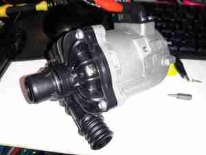
Pierburg WUP1
Pierburg WUP1

With some recent upgrades to the boat’s heating system, the hot water circulation pumps we’ve been using are becoming far too small for the job. After the original Johnson Marine circulation pump died of old age (the brushes wore down so far the springs ate the commutator) some time ago, it was replaced with a Pierburg WUP1 circulation pump from a BMW. (As we’re moored next to a BMW garage, these are easily obtainable & much cheaper than the marine pumps).

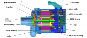
WUP1 Cutaway
WUP1 Cutaway

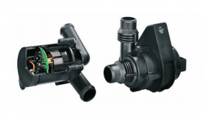
These are also brushless, where as the standard Johnson ones are brushed PM motors – the result here is a much longer working life, due to fewer moving parts.

The rated flow & pressure on these pumps is pretty pathetic, at 13L/min at 0.1bar head pressure. As the boat’s heating system is plumbed in 15mm pipe instead of 22mm this low pressure doesn’t translate to a decent flow rate. Turns out it’s pretty difficult to shove lots of water through ~110ft of 15mm pipe ;). Oddly enough, the very low flow rate of the system was never a problem for the “high output” back boiler on the stove – I suspect the “high output” specification is a bit optimistic.
This issue was recently made worse with the addition of a Webasto Thermo Top C 5kW diesel-fired water heater, which does have it’s own circulation pump but the system flow rate was still far too low to allow the heater to operate properly. The result was a rapidly cycling heater as it couldn’t dump the generated hot water into the rest of the system fast enough.

The easiest solution to the problem here is a larger pump with a higher head pressure capability. (The more difficult route would be completely re-piping the system in 22mm to lower the flow resistance). Luckily Pierburg produce a few pumps in the range that would fit the job.

Pierburg CWA-50
Pierburg CWA-50

Here’s the next size up from the original WUP1 pump, the CWA50. These are rated at a much more sensible 25L/min at 0.6bar head pressure. It’s physically a bit larger, but the connector sizes are the same, which makes the install onto the existing hoses easier. (For those that are interested, the hose connectors used on BMW vehicles for the cooling system components are NormaQuick PS3 type. These snap into place with an O-Ring & are retained by a spring clip).
The CWA50 draws considerably more power than the WUP1 (4.5A vs 1.5A), and are controllable with a PWM signal on the connector, but I haven’t used this feature. The PWM pin is simply tied to the positive supply to keep the pump running at maximum speed.

Once this pump was installed the head pressure immediately increased on the gauge from the 1 bar static pressure to 1.5 bar, indicating the pump is running at about it’s highest efficiency point. The higher water flow has so far kept the Webasto happy, there will be more to come with further improvements!

CWA-50 Pump Teardown

CWA50 Cutaway
CWA50 Cutaway

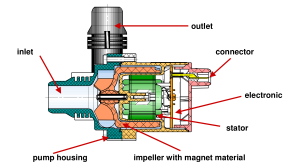
Above is a cutaway drawing of the new pump. These have a drilling through the shaft allows water to pass from the high pressure outlet fitting, through the internals of the pump & returns through the shaft to the inlet. This keeps the bearings cool & lubricated. The control & power drive circuitry for the 3-phase brushless motor is attached to the back & uses the water flowing through the rotor chamber as a heatsink. Overall these are very well made pumps.

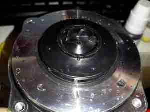
Impeller
Impeller

Here’s the impeller of the pump, which is very small considering the amount of power this unit has. The return port for the lubricating water can be seen in the centre of the impeller face.

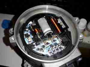
3-Phase Driver
3-Phase Driver

Inside the back of the pump is the control module. The main microcontroller is hiding under the plastic frame which holds the large power chokes & the main filter electrolytic.

Posted on Leave a comment

Eaton Variable Displacement Hydraulic Pump Repair

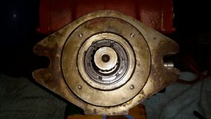
In the process of going through the boat mechanically, ready for this year’s cruising season, some damage was discovered on the face of the main hydraulic propulsion pump that drives the propeller.

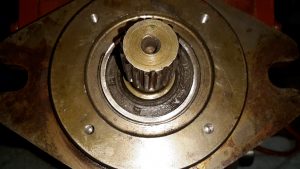
Face Damage
Face Damage

Here’s the front face of the pump, with it’s drive shaft. The circular ridge isn’t supposed to be there, it’s meant to be completely flat.
The central hub of the Centaflex coupling managed to loosen itself on the shaft (they’re pretty badly designed), and when the steel hub moved backward, it ground a very nice recess into the cast iron pump housing.
This managed to get deep enough where it compromised the circlip groove that holds both the oil seal & the mainshaft thrust bearing in place.

Spacer Ring
Spacer Ring

To save a considerable amount of cash (replacing the entire base casting of the pump would be hideously expensive), a 6mm ring was machined from steel, to hold the seal in place.
The face of the pump was then drilled & tapped for M5 screws.

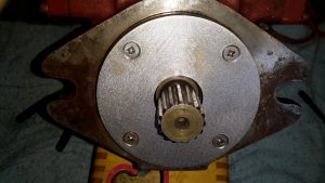
Plate Fitted
Plate Fitted

Above, the repair plate has been fitted, with the spacer ring sandwiched between it & the oil seal, securing everything in place.

Having a replaceable wear plate screwed to the front of the pump also allows for easy future repair if the coupling moves again.

Posted on Leave a comment

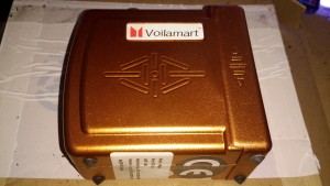
eBay Airbrush & Compressor

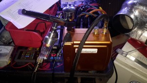
For my latest project, I needed an easier way to paint without messing about with brushes, and the associated marks they leave in a paint job. eBay provided me with a cheap airbrush & compressor.

Airbrush Kit
Airbrush Kit

For less than £30, this kit doens’t look so bad. I’ve never used an airbrush before, but I’ve had no problems with this as yet spraying both water based paints & solvent based paints.

Compressor
Compressor

Here’s the compressor itself, this runs on 12v & has an output pressure of 1.5 Bar, which is supposed to be adjustable.

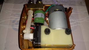
Compressor Internals

Removing a couple of screws reveals the internal components. Nothing much unusual here, a DC diaphragm pump, pressure switch & outlet fittings. There’s also a thermal cutout fitted next to the motor for protection.
The pressure switch attached to the manifold trips at 1.5Bar, keeping the pressure to the brush pretty much constant.

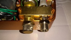
Air Block
Air Block

Next to the air outlet fitting is an adjustment knob, supposedly for varying the pressure. However it’s just a piss-poorly designed adjustable relief valve that vents to atmosphere. There’s not much of a control range.

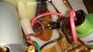
Messy Wiring
Messy Wiring

The wiring gets a bit messy where the power LED is concerned, with no heatshrink over the solder joints, but it’s adequate.

Airbrush
Airbrush

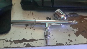
The airbrush itself isn’t too bad. It’s solid Brass, with a very nice Chrome finish. I’m not expecting miracles from a very cheap tool, but it certainly seems to be reasonable.

Water Trap
Water Trap

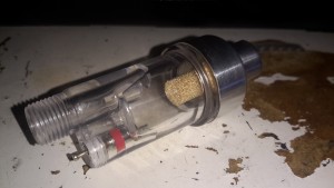
A moisture trap is supplied for the brush, to prevent water drops being sprayed out with the paint. Very handy.

Posted on Leave a comment

Duratool ZD-915 12v Conversion

Inkeeping with everything else in my shack being low voltage operated, I had planned from the outset to convert the desoldering station to 12v operation. It turns out this has been the easiest tool to convert in my shack so far.

PSU Outputs
PSU Outputs

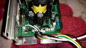
The factory SMPS is a fairly straightforward 18v 12A unit, with only a single small oddity: the desoldering gun’s heating element is controlled from inside the supply.

Iron MOSFET
Iron MOSFET

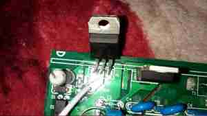
Next to the output rectifier on the heatsink is a large MOSFET, in this case a STP60NF06 from ST Micro. This is a fairly beefy FET at 60v & 60A capacity, RDS On of <0.016Ω.
This is driven via an opto-isolator from the main logic board. I’ve not yet looked at the waveform on the scope, but I suspect this is also being PWM’d to control temperature better when close to the set point.

Iron Element Controller

Rather than fire up the soldering iron & build a new element controller circuit (Lazy Mode™), I opted to take a saw to the original power supply. I cut the DC output section of the PCB off the rest of the supply & attached this piece back to the frame of the base unit. I also added a small heatsink to the MOSFET to make sure it stays cool.

12v Power Supply
12v Power Supply

Since the fan & vacuum pump are both already 12v rated, those are connected directly to the DC input socket, that I’ve installed in place of the original IEC mains socket. The 18v for the heating element is generated by a 10A DC-DC converter, again from eBay.

Oddly, the iron itself is rated at 24v 80W, but the factory supply is only rated to 18v. I’m not sure why they’ve derated the system, but as the station already draws up to 10A from a 13.8v supply, increasing the voltage any further would start giving my DC supplies a problem, so it can stay at 18v for now.

Posted on Leave a comment

nb Tanya Louise – Compressor Install

Compressed air is a rather useful power source, especially when all maintenance is done by the on board crew instead of by boatyards.

Screwfix had a good deal on a 50L 3.5CFM air compressor, to save space this has been permanently mounted in a free space & air will be piped to where it is needed from a central point.

Because of the total height of the machine, the compressor itself has been unbolted from the tank, a copper line connecting the two back together at a larger distance.

Bearers
Bearers

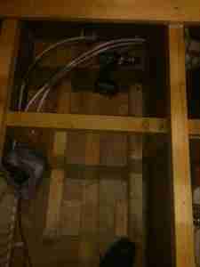
In one of the very few free spaces available, under a bunk. A pair of timbers has been screwed to the floor to support the tank.

Tank Installed
Tank Installed

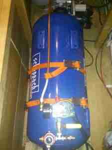
The tank is strapped to the wooden supports with a pair of ratchet straps, the compressor itself can be seen just behind the tank. The copper line on the top of the tank is going back to be connected to the compressor outlet.

Air Fittings
Air Fittings

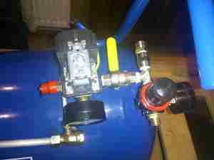
Compressor control remains on top of the tank, the pressure switch & relief valve centre. After an isolation valve, the feed splits, the regulator installed will be feeding the air horn with 20PSI, replacing the existing automotive-style 12v air pump. The currently open fitting will be routed to a quick connect on the bulkhead. This will be accessible from the front deck, an air hose can be fitted to get a supply anywhere on board.

More to come when the rest of the system gets installed!

73s for now.

Posted on Leave a comment

Marine Potable Water Management System

LCD Panel
LCD Panel

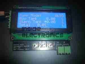
Having two separate water tanks on nb Tanya Louise, with individual pumps, meant that monitoring water levels in tanks & keeping them topped up without emptying & having to reprime pumps every time was a hassle.
To this end I have designed & built this device, to monitor water usage from the individual tanks & automatically switch over when the tank in use nears empty, alerting the user in the process so the empty tanks can be refilled.

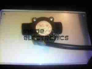
Based around an ATMega328, the unit reads a pair of sensors, fitted into the suction line of each pump from the tanks. The calculated flow is displayed on the 20×4 LCD, & logged to EEPROM, in case of power failure.

Water Flow Sensor
Water Flow Sensor

When the tank in use reaches a preset number of litres flowed, (currently hardcoded, but user input will be implemented soon), the pump is disabled & the other tank pump is enabled. This is also indicated on the display by the arrow to the left of the flow register. Tank switching is alerted by the built in beeper.
It is also possible to manually select a tank to use, & disable automatic operation.
Resetting the individual tank registers is done by a pair of pushbuttons, the total flow register is non-resettable, unless a hard reset is performed to clear the onboard EEPROM.

Main PCB
Main PCB

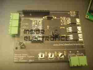
View of the main PCB is above, with the central Arduino Pro Mini module hosting the backend code. 12-24v power input, sensor input & 5v sensor power output is on the connectors on the left, while the pair of pump outputs is on the bottom right, switched by a pair of IRFZ44N logic-level MOSFETS. Onboard 5v power for the logic is provided by the LM7805 top right.

Code & PCB design is still under development, but I will most likely post the design files & Arduino sketch once some more polishing has been done.

Posted on 1 Comment

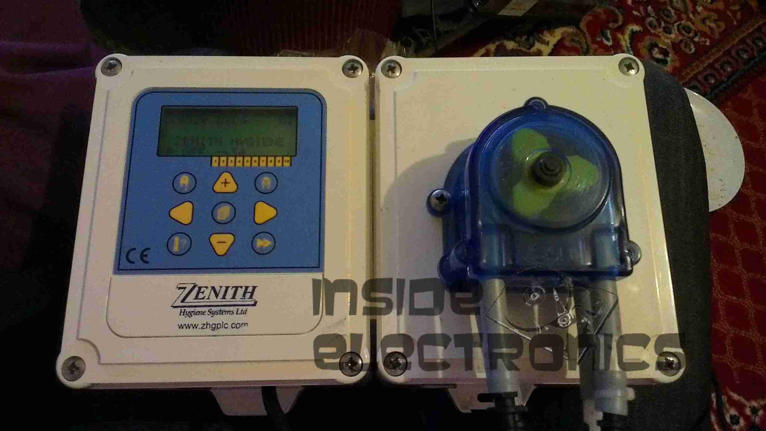
Brightwell Brightstar II BSL4 Dosing System

Overview
Overview
Overview

Here is an old chemical dosing system for industrial washing machines. These units are 4-pump models, with dual pumpheads. The motors are reversed to operate alternate pumps in the same head.

Label
Label

From 2006, this is a fairly old unit, and made in the UK.

CPU Board
CPU Board

Main controller PCB, with interface to the power electronics via the ribbon cable, an external serial port for programming to it’s left. Powered by an ST microcontroller. The LCD is below this board.

PCU & Driver PCBs
PCU & Driver PCBs

Main power supply, sense input & motor driver boards. The PSU outputs +5v, +12v & +24v. The inputs on the lower left connect to the washing machine & trigger the pumps via the programming on the CPU. The motors are driven by L6202 H-Bridge drivers from ST.

Motor Assembly
Motor Assembly

Motor & gearbox assembly on the back of the pumphead. These are 24v DC units with 80RPM gearboxes.

UPDATE:
As it seems to be difficult to find, here is the user manual for this unit:
[download id=”5557″]
Posted on 4 Comments

Audi TT Roof Hydraulics

Pump
Pump

This is the hydraulic system from an Audi TT that would power the soft top. Here is the hydraulic pump unit. Oil Tank is on the left. Power is 12v DC at ~20A

Cylinders
Cylinders

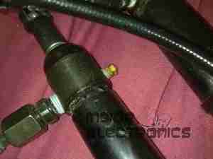
The pair of hydraulic cylinders that attached to the roof mechanism.

Limit Switch
Limit Switch

One of the cylinders has a limit switch built in. The brass bolt coming out of the side of the head is one contact. The other contact is the cylinder body.

Hose
Hose

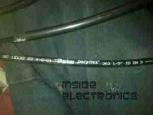
Marking on the hoses. This is Parker Polyflex hydraulic hose. 1/8″ ID.

Motor
Motor

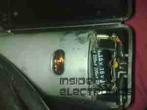
Drive motor for the hydraulic pump. Standard DC permanent magnet motor.

Motor Suppression
Motor Suppression

Motor power terminals & suppression capacitors. As the reversing relays actually short the motor out when de-energized, there is a lot of arcing at the brushes without some suppression.

Reversing Relays
Reversing Relays

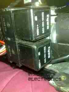
Reversing relay stack. Each relay is a SPDT configuration. The pair are arranged as a DPDT bank to reverse the motor, depending on which relay is energized.

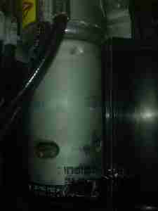
Tank
Tank

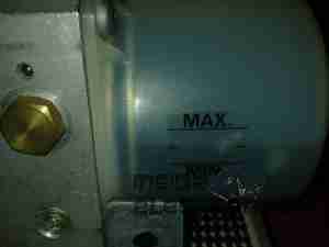
Detail of the oil tank showing the level markings.

Power Valve
Power Valve

Solenoid valve on top of the unit. This valve provides full pump pressure to the cylinders when energized.

Posted on Leave a comment

532nm DPSS Module

DPSS Module
DPSS Module

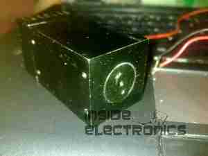
A quick post documenting a DPSS laser module i salvaged from a disco scanner. Estimated output ~80mW

Diode Connection
Diode Connection

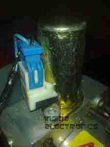
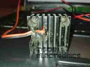
Connection to the 808nm pump diode on the back of the module. There is a protection diode soldered across the diode pins. (Not visible). Note heatsinking of the module.

Driver PCB
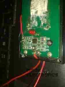
Driver PCB

Driver PCB. This module was originally 240v AC powered, with a transformer mounted on the PCB with a built in rectifier & filter capacitor. I converted it to 5v operation. Emission LED on PCB.

Output
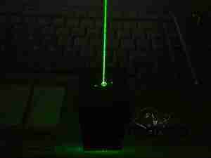
Output

Output beam from the module.

Posted on Leave a comment

Fluval 203 Canister Filter

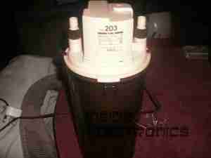
Assembly
Assembly

Here is an old fish tank external filter & a few pics of the insides.

Label
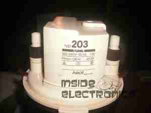
Label

Label on the front of the pump head. Fittings on either side of the motor are water I/O.

Pump
Pump

Underside of the pump head, inlet is on the right, outlet from the pump is on the left. Pump intake in centre.

Pump Parts
Pump Parts

Pump disassembled. This pump requires no shaft seals as the impeller is driven magnetically with a synchronous motor.

Filter Stack
Filter Stack

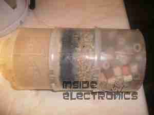
Filter stack removed from the unit. From left: foam media, activated charcoal/gravel & ceramic pellets.