So it’s time to get the propulsion system underway for the trolley, a pair of wheelchair motors were sourced for this, from HacMan. Since I don’t know how many hours are on these units, or how they’ve been treated in the past, I’m going to do a full service on them to ensure reliability. I decided on wheelchair motors due to their extreme ruggedness & heavily built components – this project when complete is going to weigh in at about 150kg!
I suspected something was amiss with one of the motors from running them under no load: the left hand wheelchair motor was heating up to the point of being too hot to touch, so this one at the very least needed some investigation.
Motor Disassembly & Assessment
Rear Cover Removed
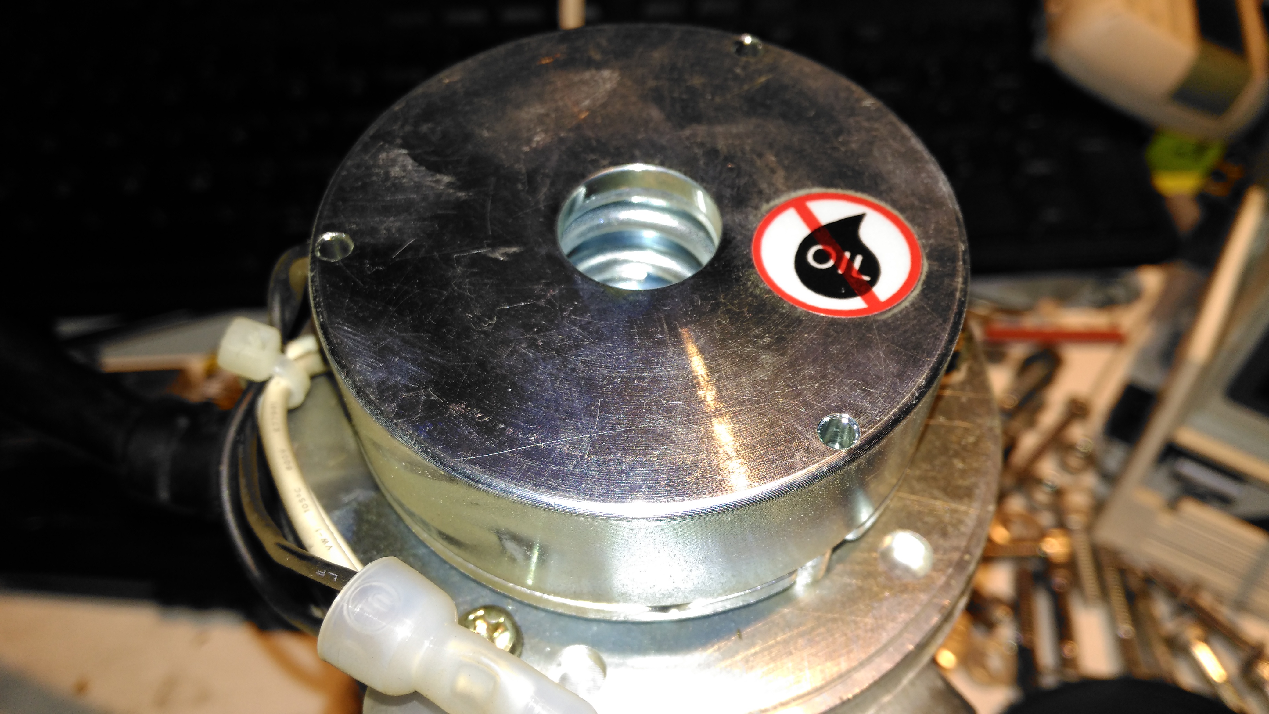
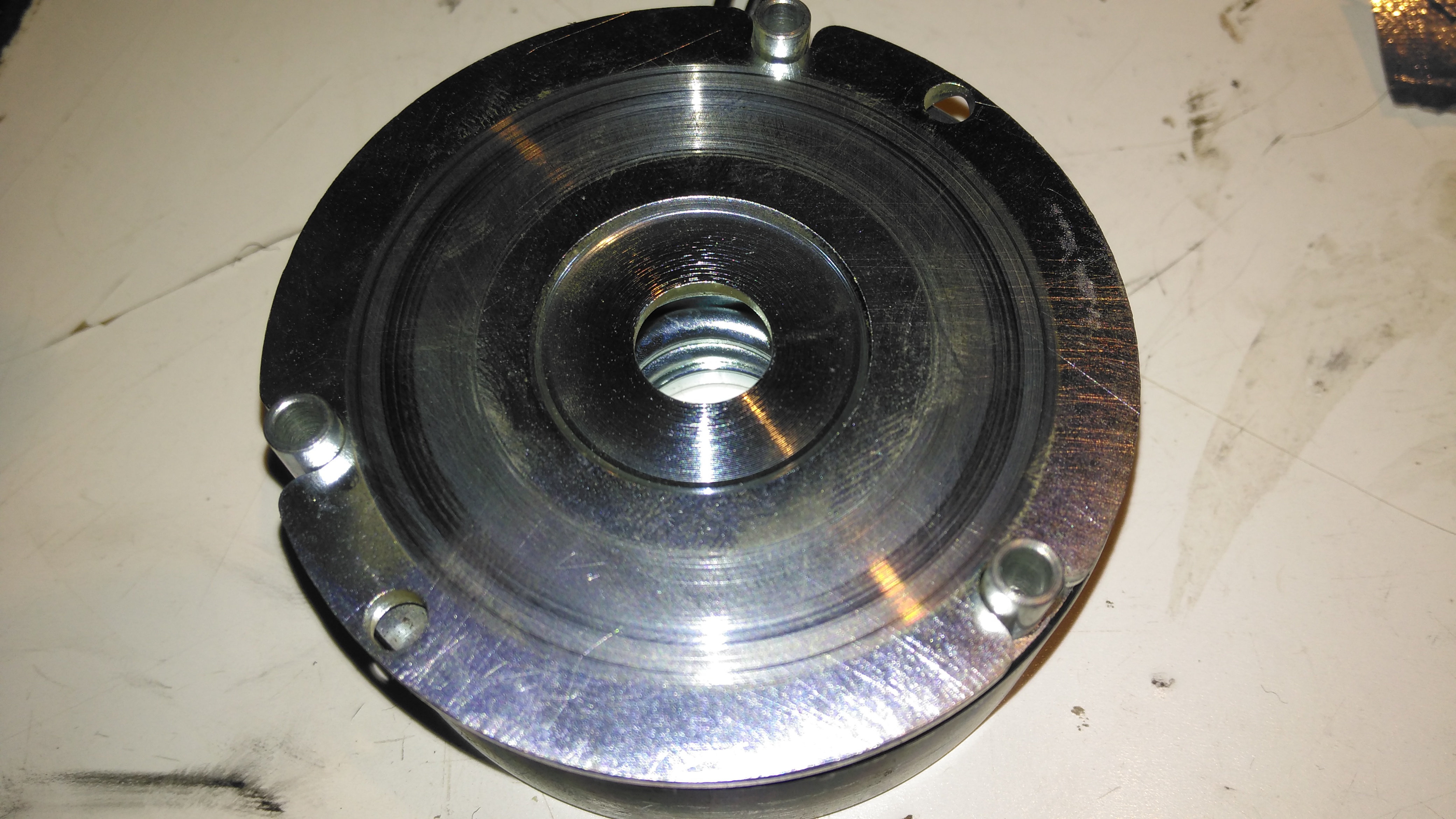
With the back cover removed from the motor the electromagnetic brake is revealed. This engages when power is removed to stop the motor freewheeling, which even though it’s a wormdrive box, it will do readily if backdriven.
Electromagnetic Brake Assembly
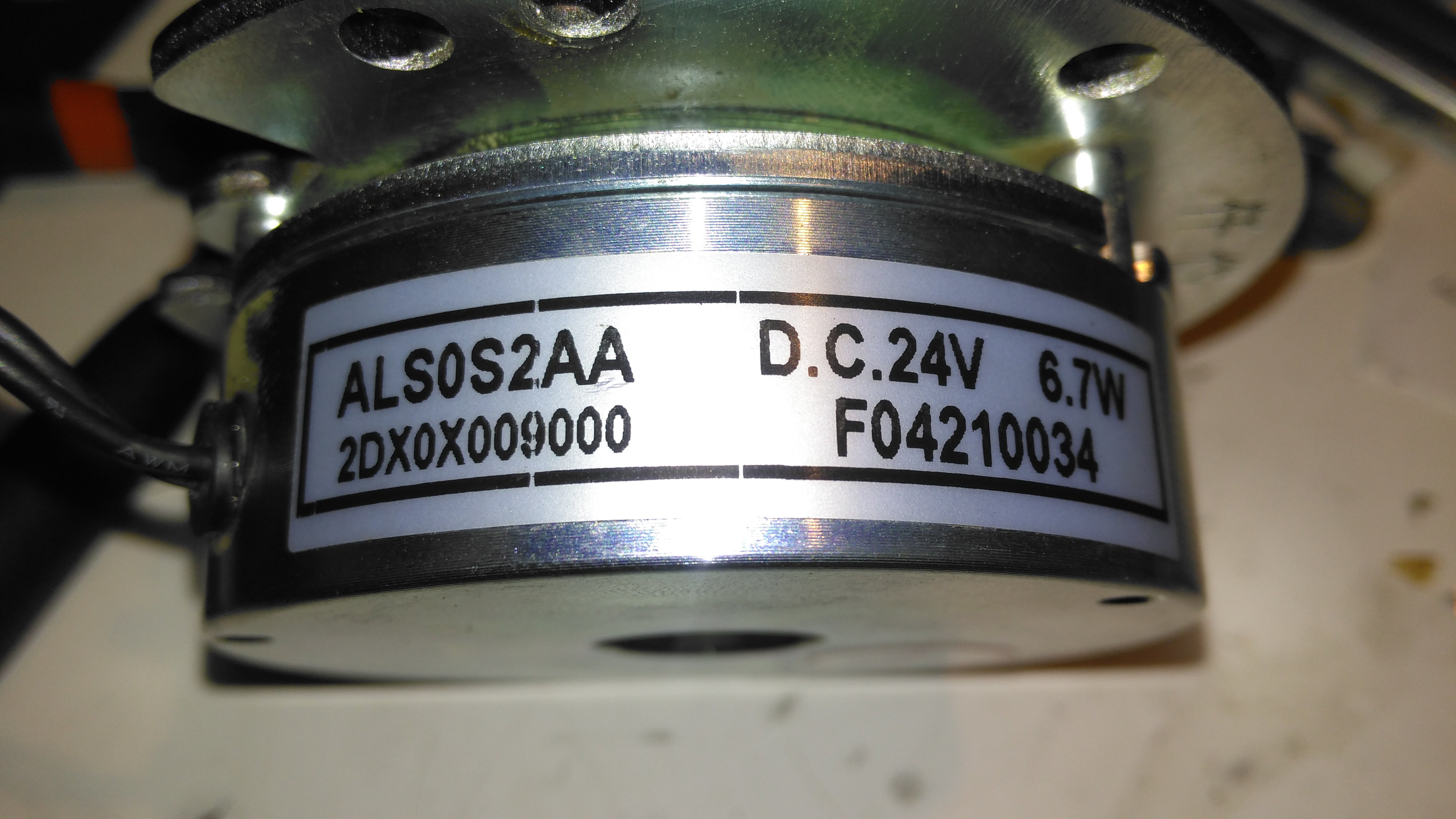
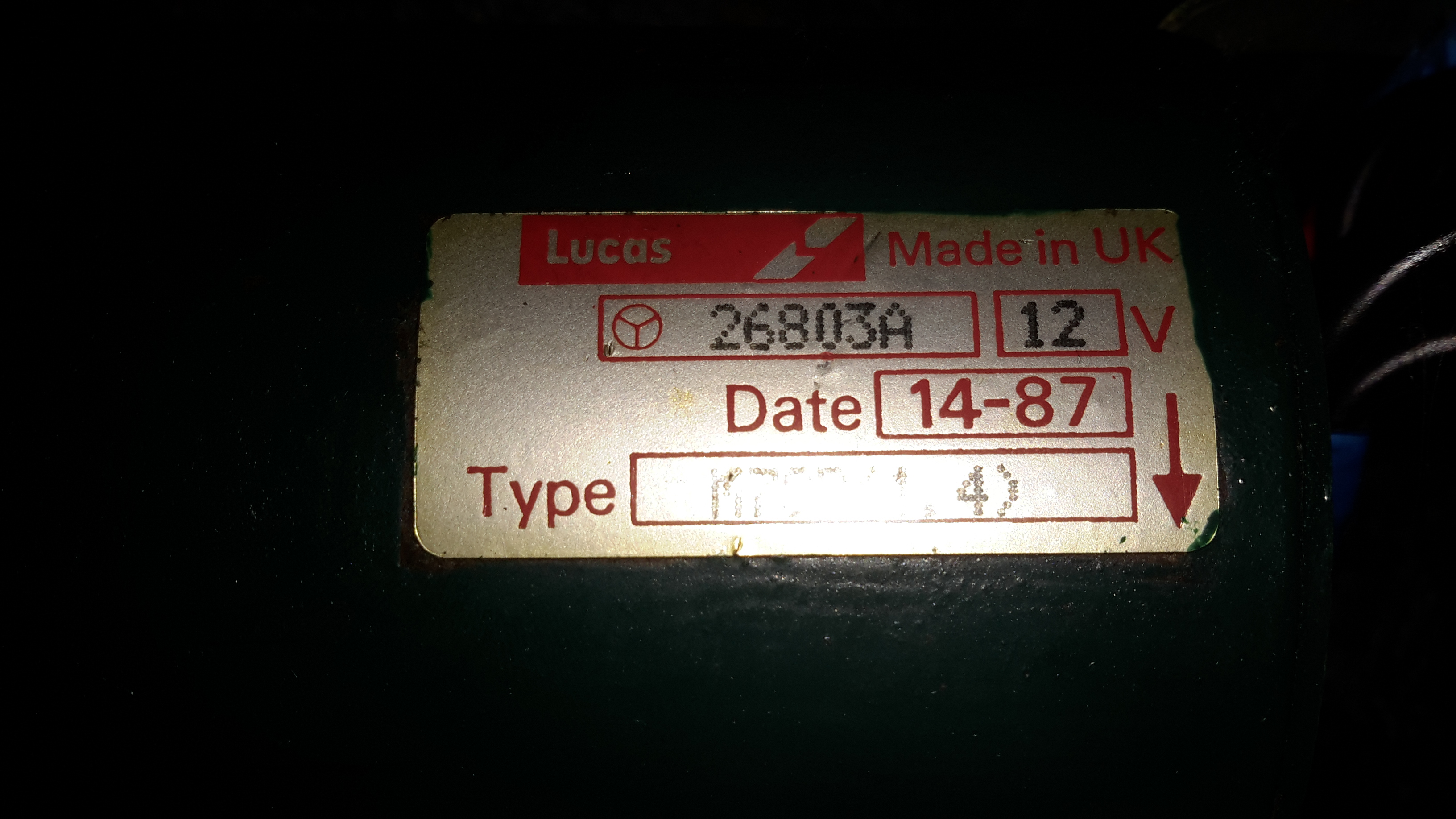
The brake is rated 6.7W at 24v DC.
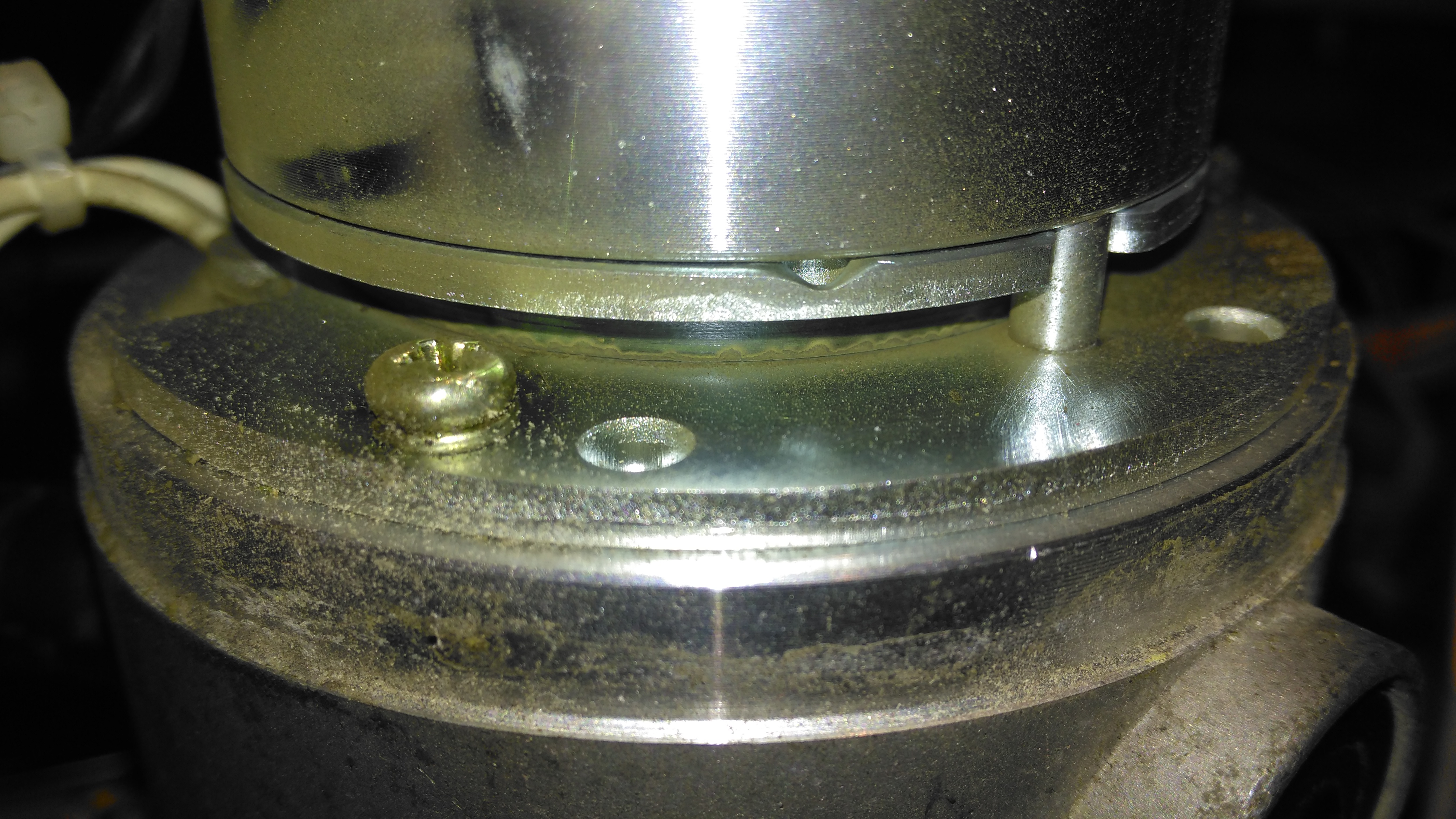
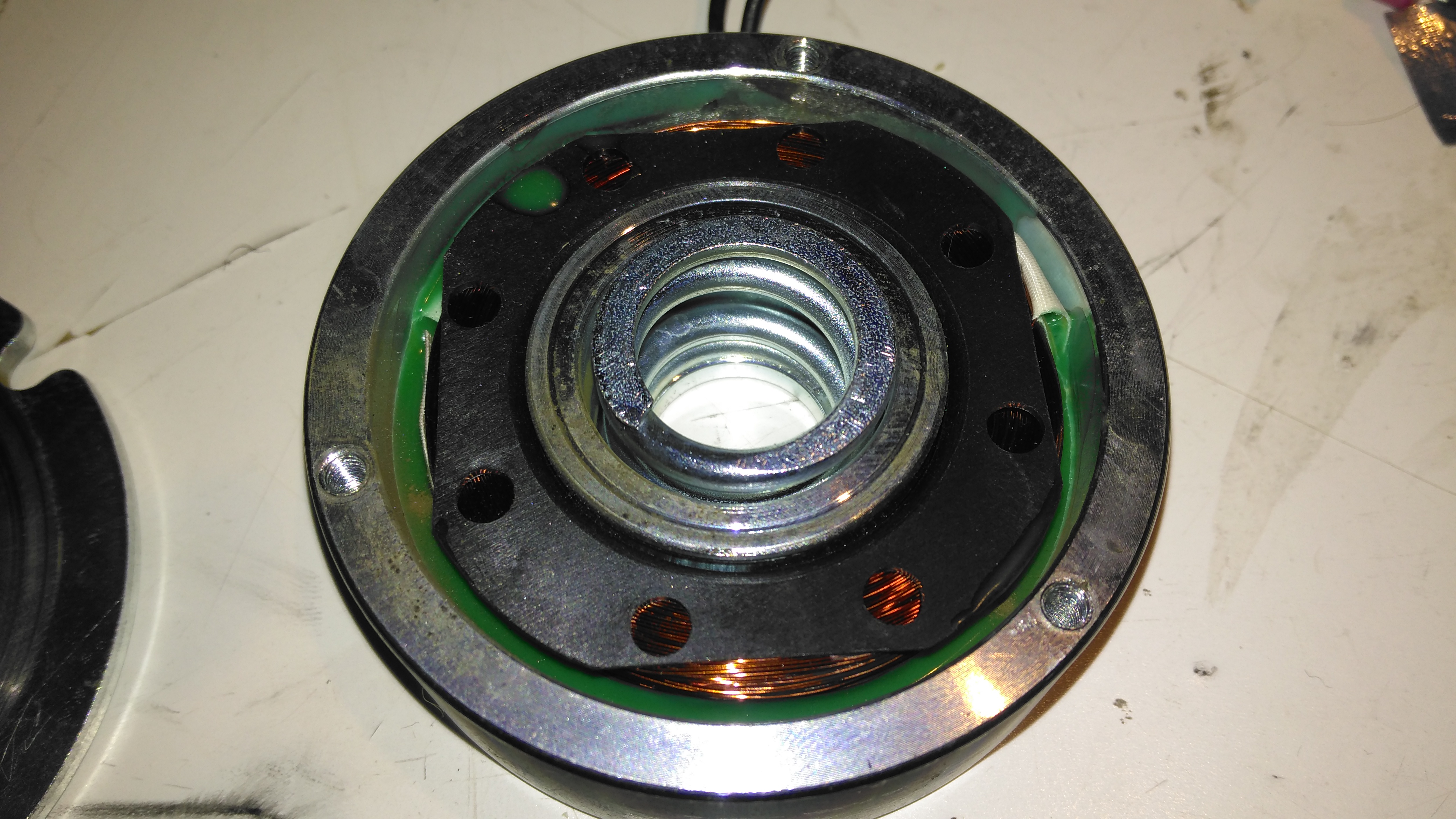
Brake Disc
The brake disc is just visible between the plates of the brake here, with some green dust worn off the disc. When power is applied, the top disc, just under the magnet on top, is pulled upward against spring pressure away from the brake disc, which is attached to the motor armature.
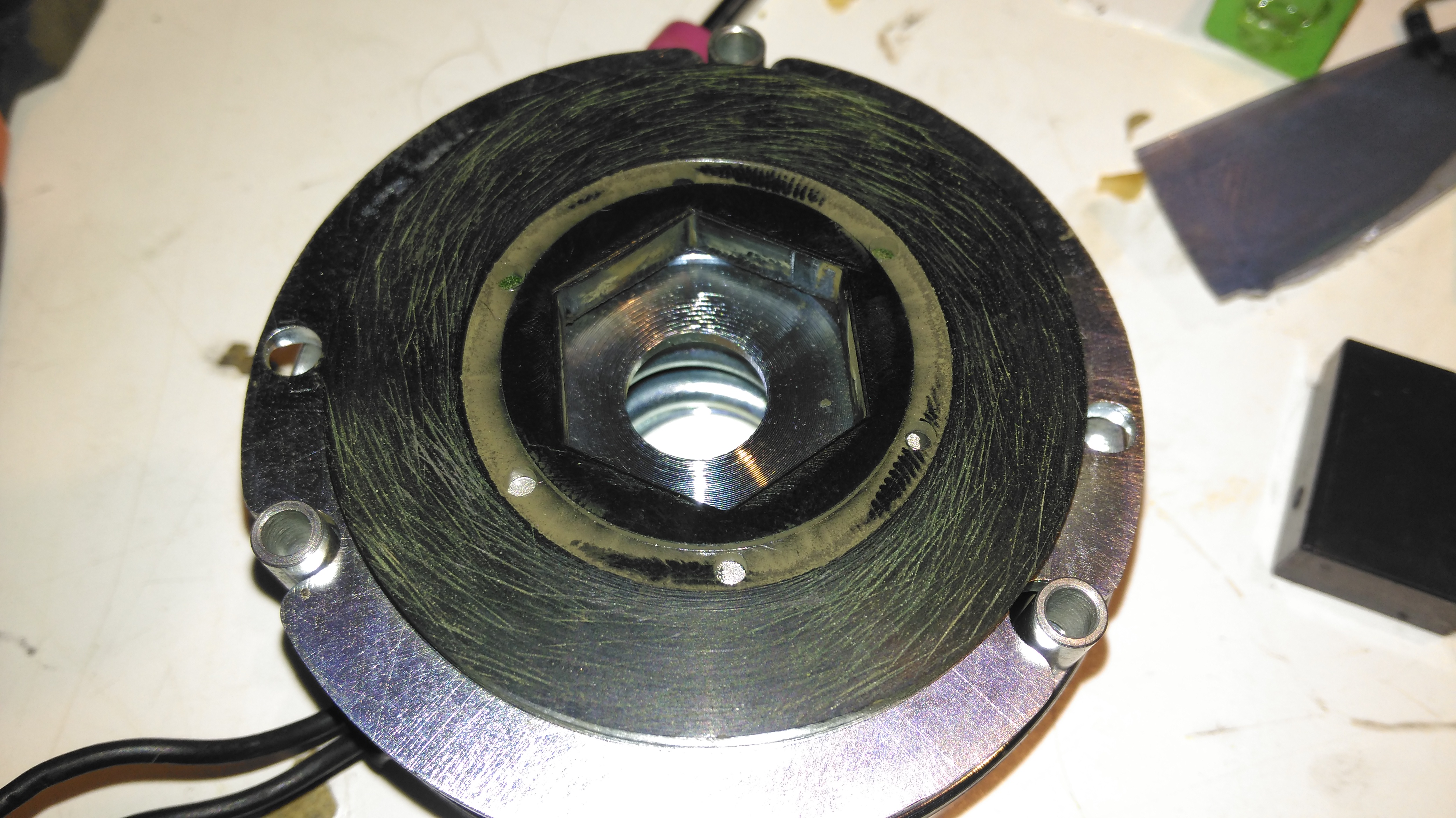
Brake Disc
Here’s the brake disc, removed from the motor. There’s only a little wear here, as I’d expect – these brakes don’t engage until the motors have come to a complete stop.
Brake Actuator
The steel disc above the magnet acts as one of the friction surfaces of the brake.
Brake Solenoid
Finally, the solenoid is at the back, partially potted in resin. The strong coil spring in the centre applies the brakes when power is disconnected.
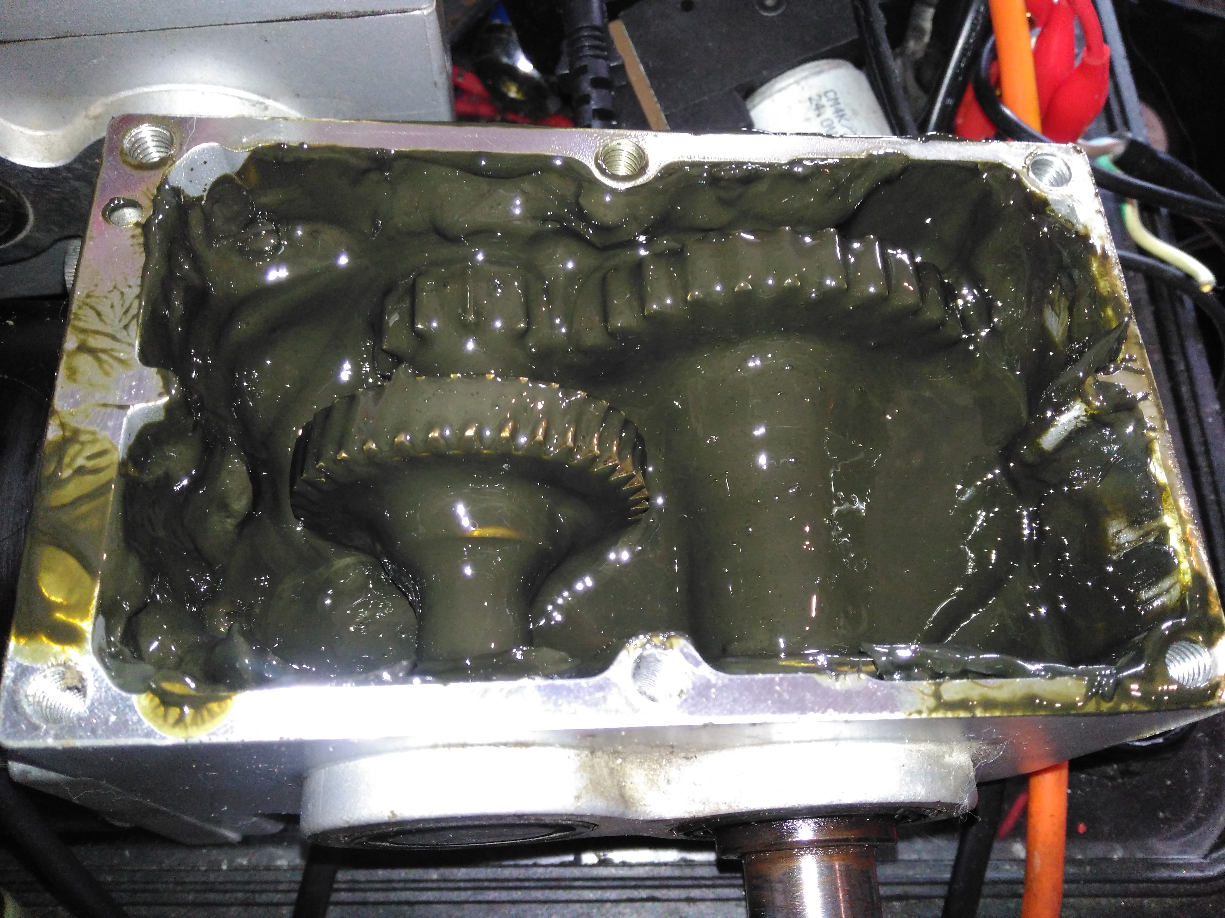
Gearbox Grok
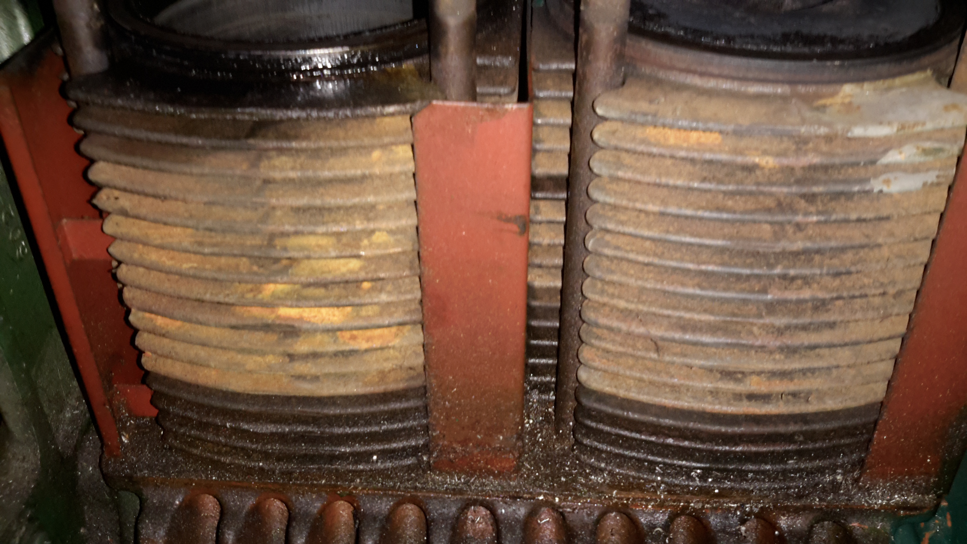
Removing the top of the gearbox reveals the state of the internals – There’s no wear at all on the gearset, but the lubricant is totally manky. The external oil seals have been leaking for some time, letting water in and grease out. The emulsified result is revolting! These gearboxes have a wormdrive first stage, the worm gear is underneath the left hand gearset. Steel spur gears then do the final gearing to the output shaft. The output gear is splined onto the output, and can slide along the shaft out of mesh – this is the freewheel clutch mechanism. At the moment it’s all obscured by the disgusting lubricant.
Input Shaft Seal
Here’s the failed seal on the left hand gearbox, the face damage was done by petrol immersion to clean everything up. (The seal is already compromised, so I’m not fussed about solvents eating the remaining rubber). The motor shaft is joined to the gearbox input by a rubber coupling.
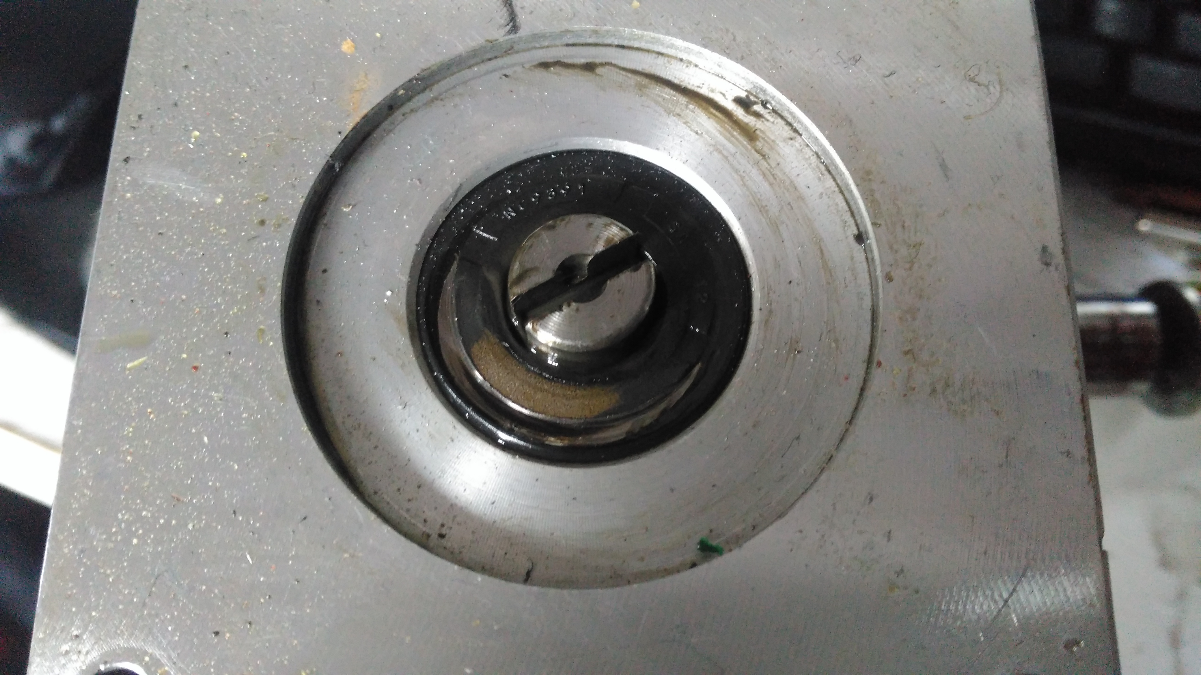
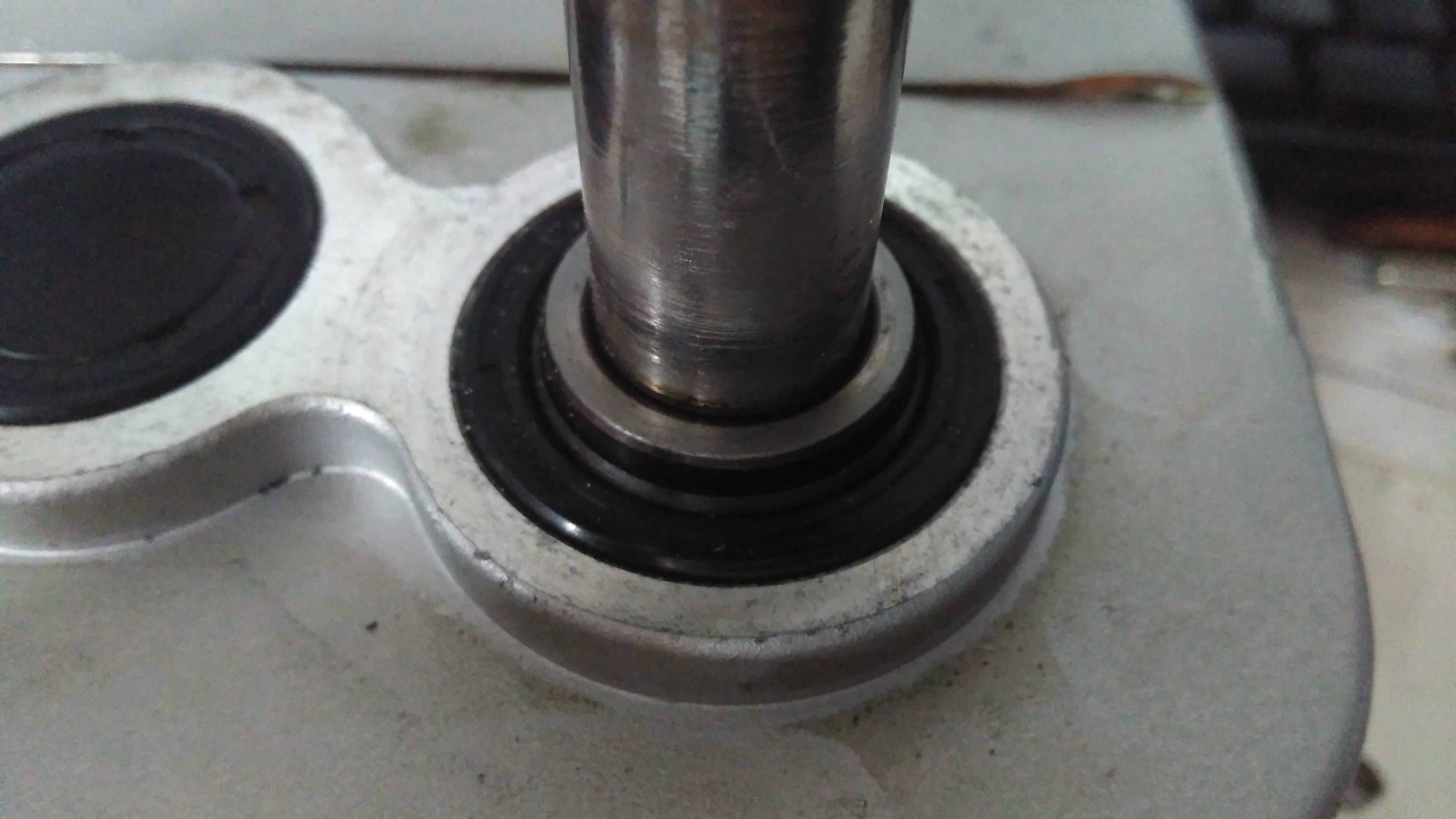
Output Shaft Seal
The output shaft seals seem to be still OK, there has been some seepage past the collar that the shaft rides in, but nothing more. This can be resealed with some Loctite bearing sealant. The sleeve is held into the gearbox by the wheel hub when in operation, but this doesn’t seal the gap unfortunately. I don’t know why the manufacturer didn’t just machine the shaft to that larger diameter, instead of using an extra sleeve to accommodate the seal.
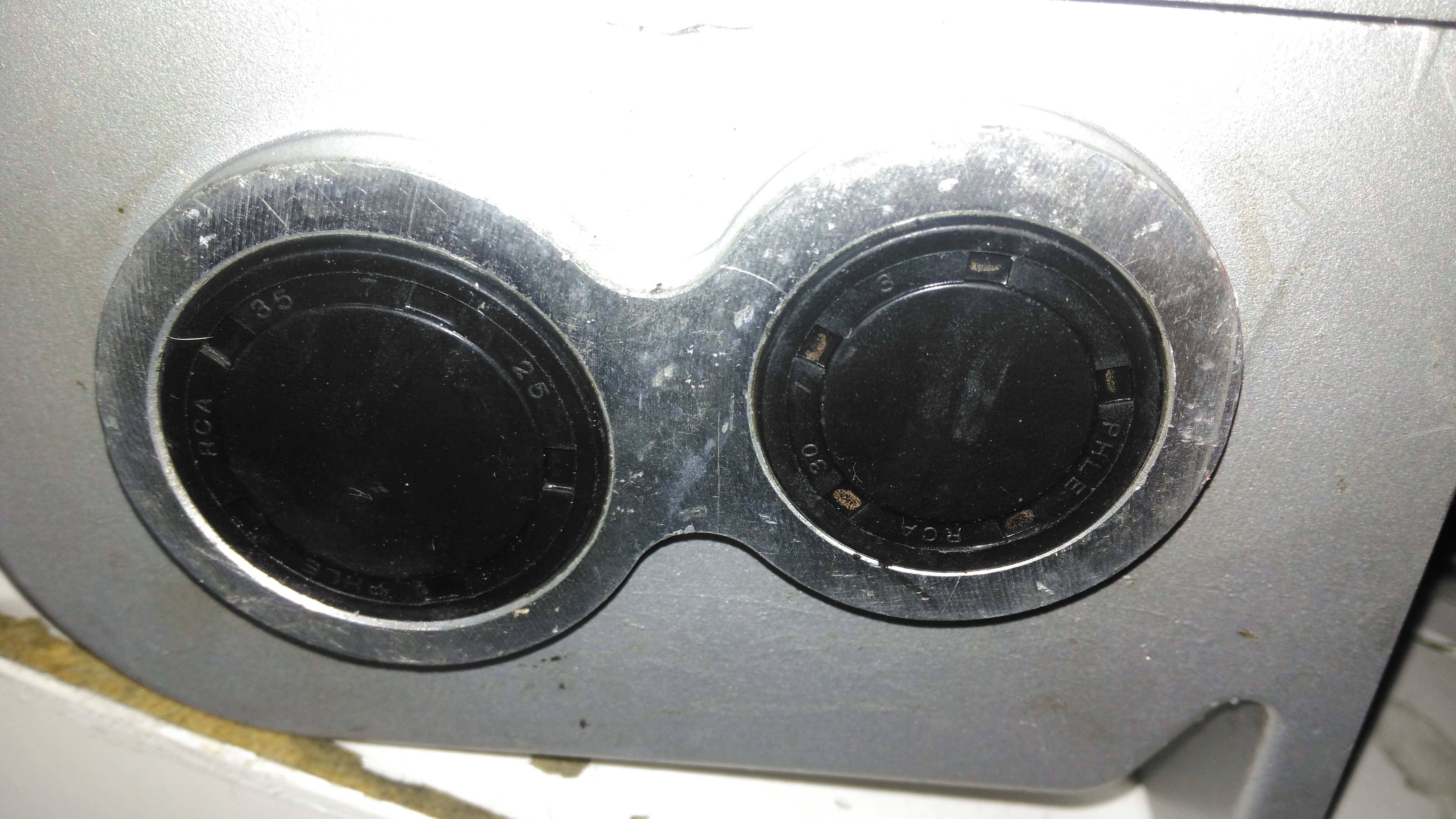
Bore Seals
The bore seals covering the ends of the shafts are also fine, which is a good thing, since I can’t seem to find replacements for these anywhere. The input shaft seals will be replaced on both gearboxes though.
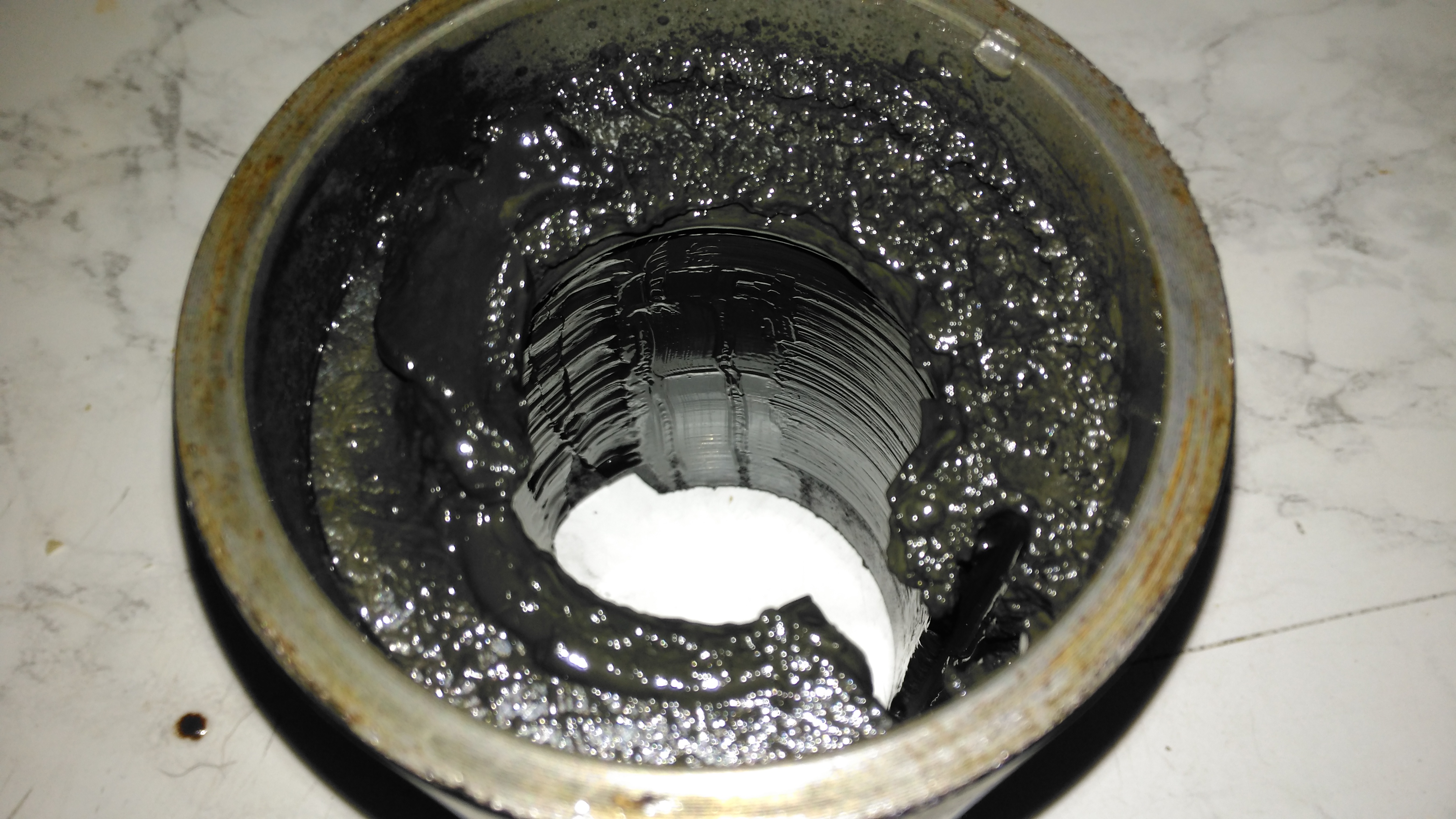
Motor Contamination
The oil seal must have been leaking for a long while! This is the gearbox end of the wheelchair motor frame, completely clogged with grease. Luckily only a small amount has made it down past the armature to the brushgear.
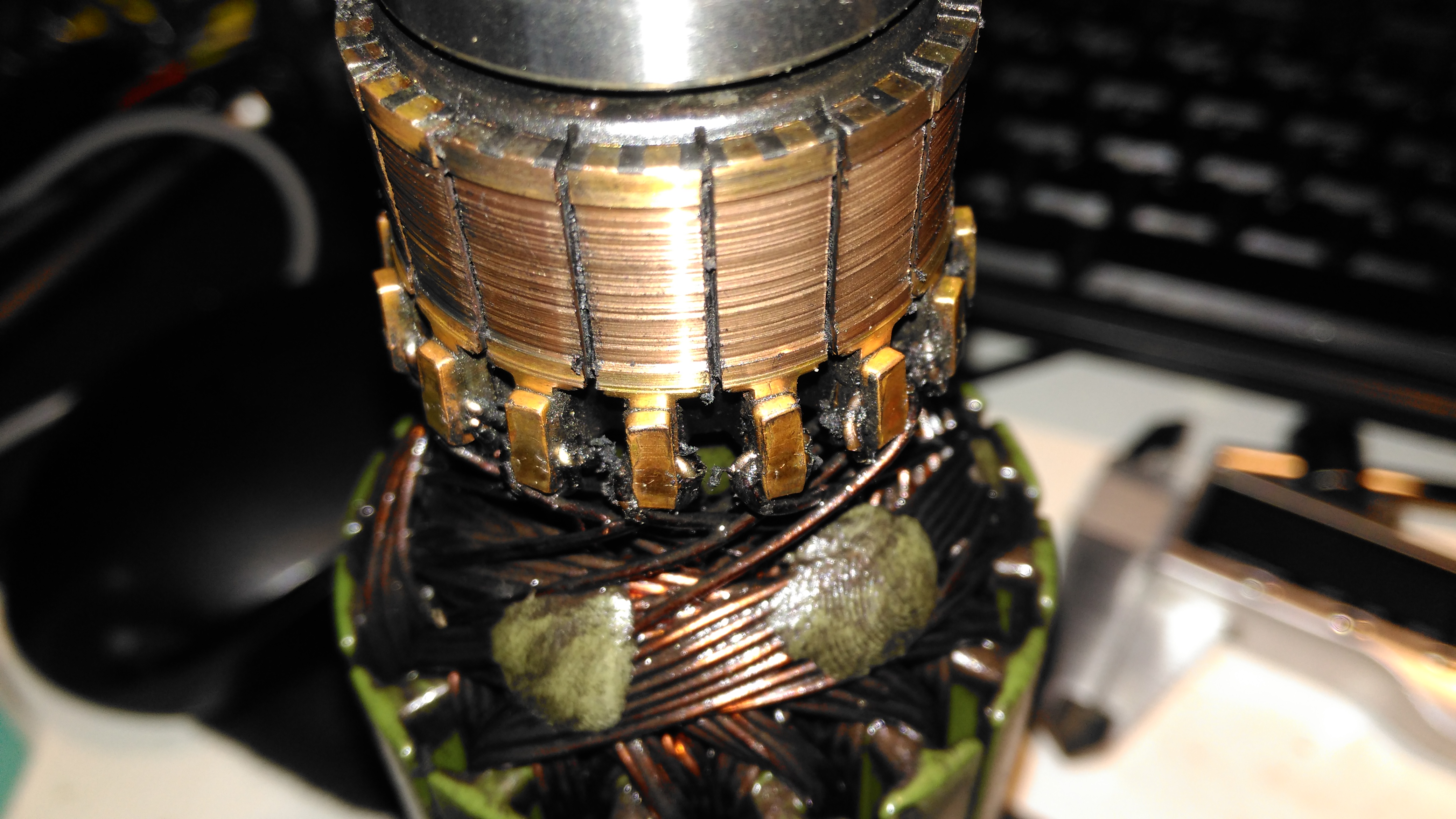
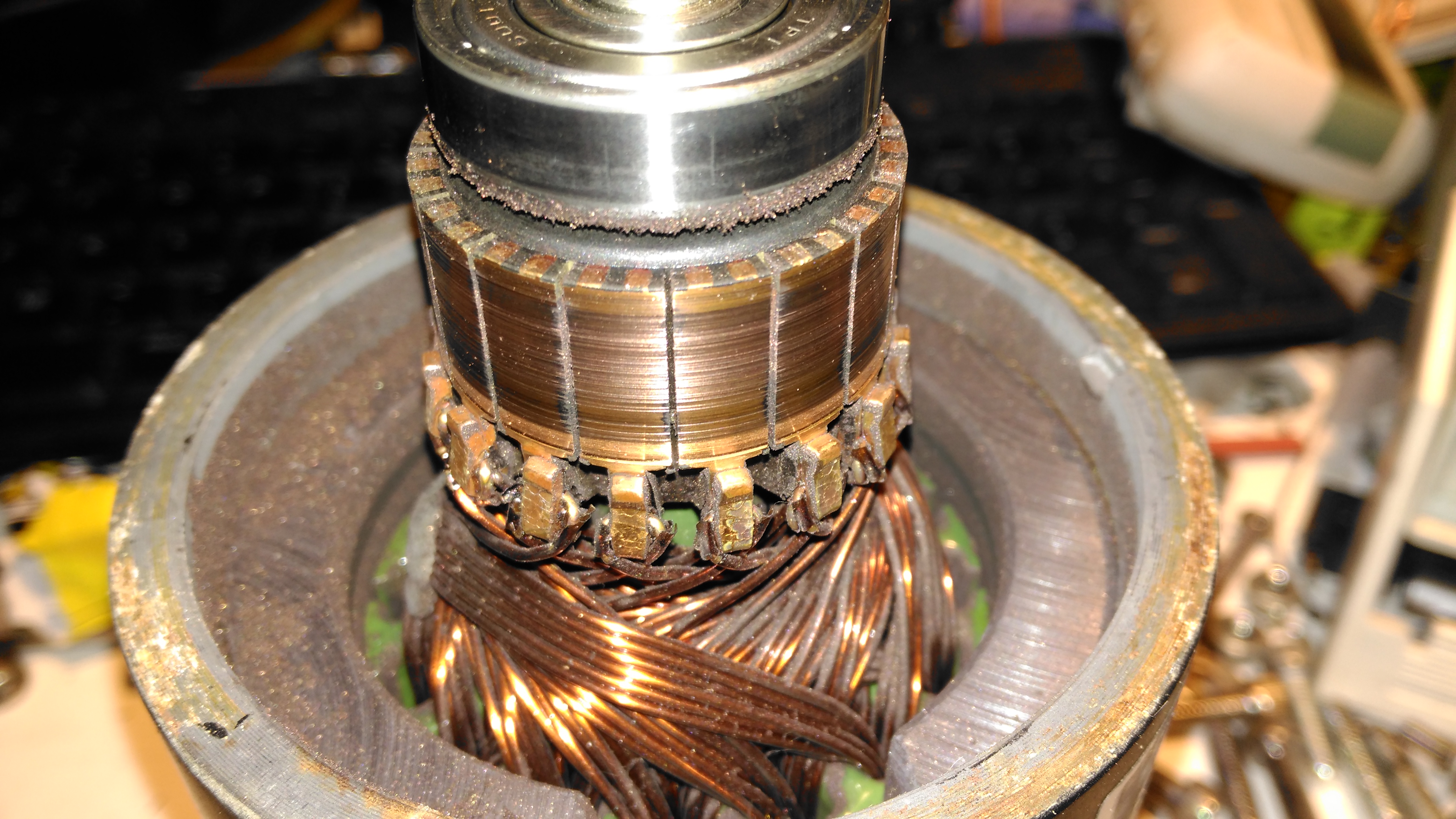
Damaged Commutator
The commutator of this motor is badly damaged, and the brushes are very worn. This has been caused by the gearbox oil seal failing, and contaminating the motor internals with lubricant. The undercut between the segments is all but gone – filled with an abrasive mixture of brush dust, copper dust & old lubricant. Some repair work will be required here.
Second Motor
Here’s the brushgear removed from the second wheelchair motor, this one looks much more normal, and there’s not as much wear on the brushes or the commutator. Just the usual coating of brush dust.
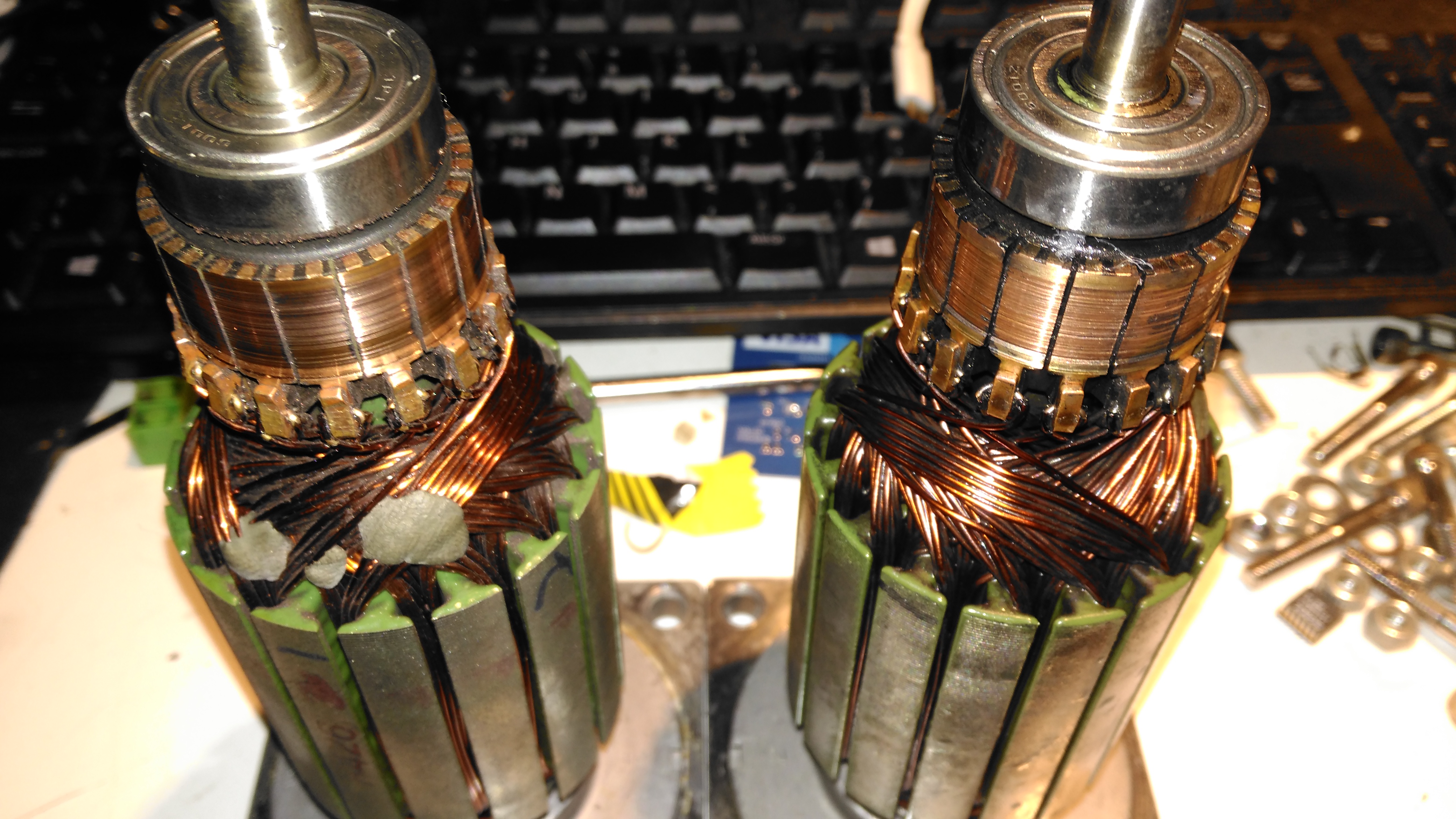
Armatures
Here’s both armatures together, with the contaminated one on the right, after some cleaning to remove most of the greasy old grok & brush dust from everything. The windings on the damaged left hand wheelchair motor haven’t darkened, which I would expect from severe overheating damage, so I’m hoping this armature is OK, and won’t require a rewind. Using an ohmmeter on these windings doesn’t tell me much – there’s only 7 turns of 0.86mm (20AWG) magnet wire in each coil, so they read as a dead short anyway. There was some leakage between the windings and the core before I cleaned things up – this was in the high (28+) megohms range, but this seems to have cleared now I’ve given things a real good cleaning.
For the latest big project, replacing the battery bank on the boat with 5 brand new 200Ah Yuasa heavy duty flooded lead acids, I’m going to need to make many short links from heavy battery cable to connect all 5 batteries into a parallel bank.
Cutting cable as big in diameter as a good sized thumb is difficult at best. In the past I’ve used a hacksaw, but it doesn’t do a very clean job, especially as the cut nears the end – strands get ripped from the cable by the relatively coarse blade & this reduces the current carrying capacity.
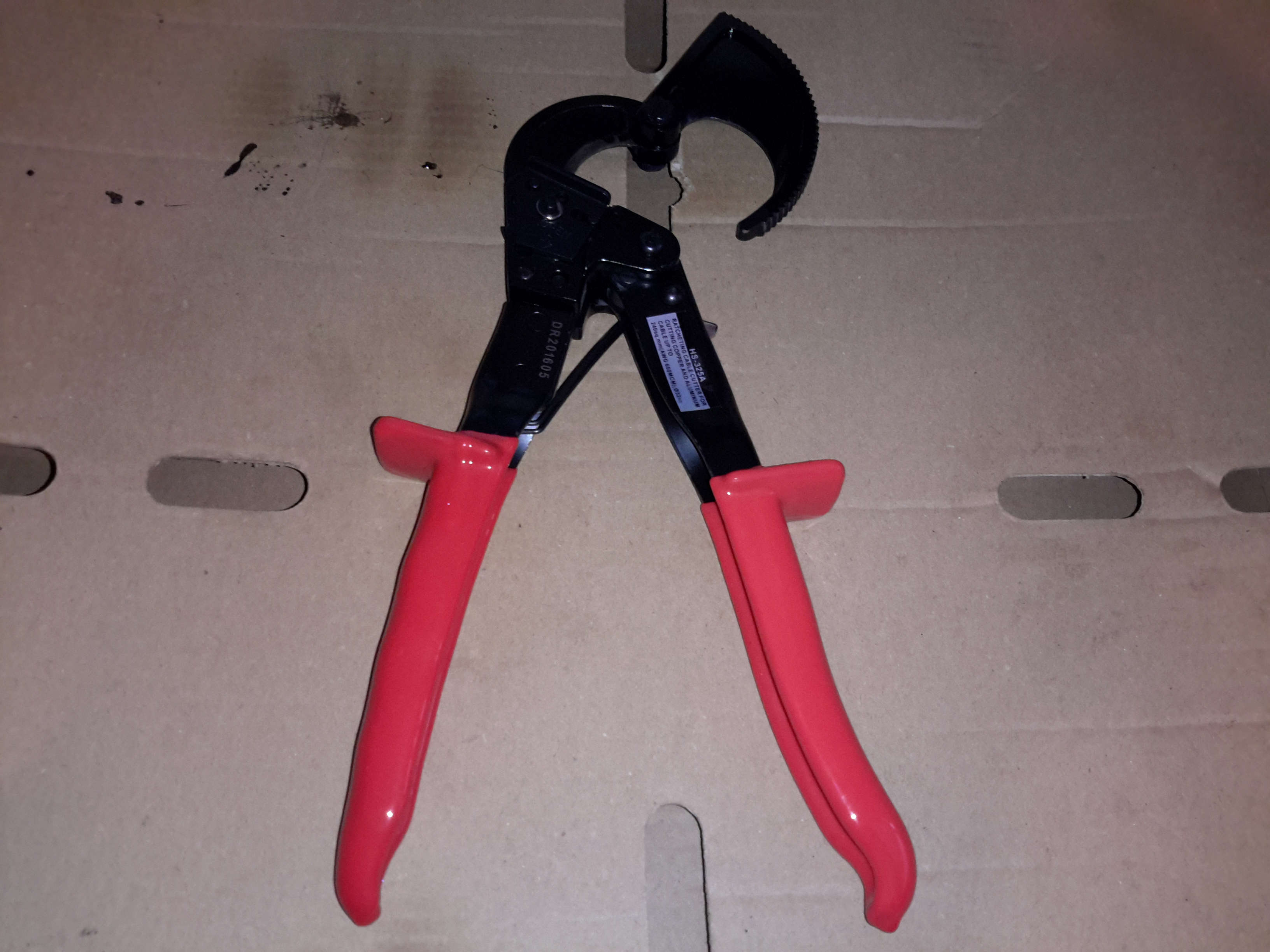
Over to eBay again netted a pair of ratchet-type heavy duty cable cutters for £30. These are rated to cut cable up to 240mm² or 600MCM.
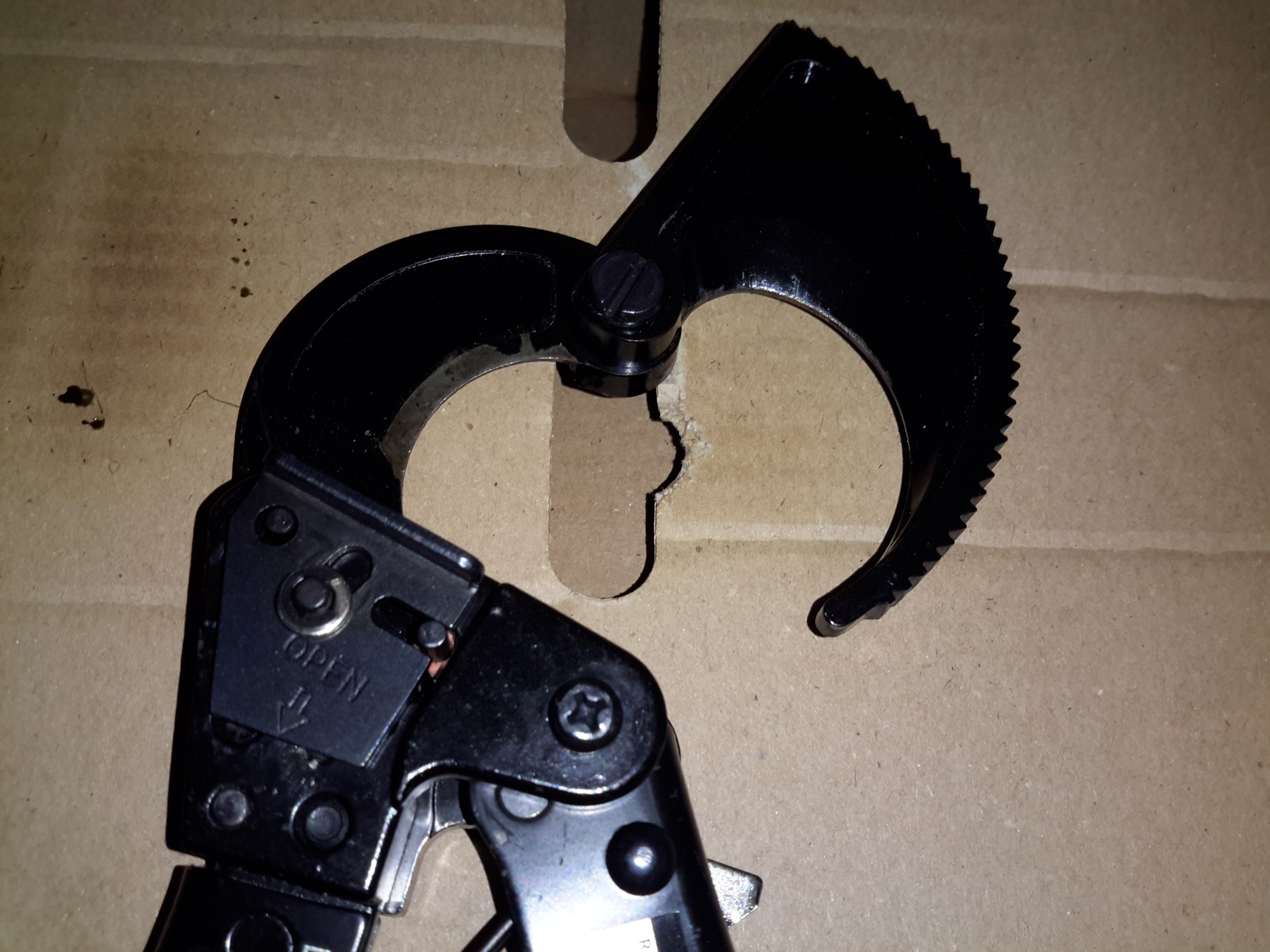
Cutting Jaws
The cutting head on these snips is massive – cutting through cable up to 35mm in diameter takes some force. The ratchet mechanism is used to get a large mechanical advantage to force the cutters through the copper, without having to resort to more expensive & complex mechanisms such as hydraulics. (Hydraulic cable cutters do exist, but cost a small fortune & are totally over-rated for the job).
Overall the tool seems to be well made, the handles are Vinyl dipped to make them more comfortable, which certainly helps when applying a large amount of force. Running a file over the cutters themselves reveals they’re actually hardened – unusual for cheapo Chinese tools.
A helium-neon (henceforth abbreviated HeNe) laser is basically a fancy neon sign with mirrors at both ends. Well, not quite, but really not much more than this at first glance (though the design and manufacturing issues which must be dealt with to achieve the desired beam characteristics, power output, stability, and life span, are non-trivial). The gas fill is a mixture of helium and neon gas at low pressure. A pair of mirrors – one totally reflective (called the High Reflector or HR), the other partially reflective (called the Output Coupler or OC) at the wavelength of the laser’s output – complete the resonator assembly. This is called a Fabry-Perot cavity (if you want to impress your friends). The mirrors may be internal (common on small and inexpensive tubes) or external (on precision high priced lab quality lasers). Electrodes sealed into the tube allow for the passage of high voltage DC current to excite the discharge.
Note that a true laser jock will further abbreviate “HeNe laser” to simply “HeNe”, pronounced: Hee-nee. Their laser jock colleagues and friends then know this really refers to a laser! 🙂 While other types of lasers are sometimes abbreviated in an analogous manner, it is never to the same extent as the HeNe.
I still consider the HeNe laser to be the quintessential laser: An electrically excited gas between a pair of mirrors. It is also the ideal first laser for the experimenter and hobbyist. OK, well, maybe after you get over the excitement of your first laser pointer! 🙂 HeNe’s are simple in principle though complex to manufacture, the beam quality is excellent – better than anything else available at a similar price. When properly powered and reasonable precautions are taken, they are relatively safe if the power output is under 5 mW. And such a laser can be easily used for many applications. With a bare HeNe laser tube, you can even look inside while it is in operation and see what is going on. Well, OK, with just a wee bit of imagination! 🙂 This really isn’t possible with diode or solid state lasers.
I remember doing the glasswork for a 3 foot long HeNe laser (probably based on the design from: “The Amateur Scientist – Helium-Neon Laser”, Scientific American, September 1964, and reprinted in the collection: “Light and Its Uses” [5]). This included joining side tubes for the electrodes and exhaust port, fusing the electrodes themselves to the glass, preparing the main bore (capillary), and cutting the angled Brewster windows (so that external mirrors could be used) on a diamond saw. I do not know if the person building the laser ever got it to work but suspect that he gave up or went on to other projects (which probably were also never finished). And, HeNe lasers are one of the simplest type of lasers to fabricate which produce a visible continuous beam.
Some die-hards still construct their own HeNe lasers from scratch. Once all the glasswork is complete, the tube must be evacuated, baked to drive off surface impurities, backfilled with a specific mixture of helium to neon (typically around 7:1 to 10:1) at a pressure of between 2 and 5 Torr (normal atmospheric pressure is about 760 Torr – 760 mm of mercury), and sealed. The mirrors must then be painstakingly positioned and aligned. Finally, the great moment arrives and the power is applied. You also constructed your high voltage power supply from scratch, correct? With luck, the laser produces a beam and only final adjustments to the mirrors are then required to optimize beam power and stability. Or, more, likely, you are doing all of this while your vacuum pumps are chugging along and you can still play with the gas fill pressure and composition. What can go wrong? All sorts of things can go wrong! With external mirrors, the losses may be too great resulting in insufficient optical gain in the resonant cavity. The gas mixture may be incorrect or become contaminated. Seals might leak. Your power supply may not start the tube, or it may catch fire or blow up. It just may not be your day! And, the lifetime of the laser is likely to end up being only a few hours in any case unless you have access to an ultra-high vacuum pumping and bakeout facility. While getting such a contraption to work would be an extremely rewarding experience, its utility for any sort of real applications would likely be quite limited and require constant fiddling with the adjustments. Nonetheless, if you really want to be able to say you built a laser from the ground up, this is one approach to take! (However, the CO2 and N2 lasers are likely to be much easier for the first-time laser builder.)
However, for most of us, ‘building’ a HeNe laser is like ‘building’ a PC: An inexpensive HeNe tube and power supply are obtained, mounted, and wired together. Optics are added as needed. Power supplies may be home-built as an interesting project but few have the desire, facilities, patience, and determination to construct the actual HeNe tube itself.
The most common internal mirror HeNe laser tubes are between 4.5″ and 14″ (125 mm to 350 mm) in overall length and 3/4″ to 1-1/2″ (19 mm to 37.5 mm) in diameter generating optical power from 0.5 mW to 5 mW. They require no maintenance and no adjustments of any kind during their long lifetime (20,000 hours typical). Both new and surplus tubes of this type – either bare or as part of complete laser heads – are readily available. Slightly smaller tubes (less than 0.5 mW) and much larger tubes (up to approximately 35 mW) are structurally similar (except for size) to these but are not as common.
Much larger HeNe tubes with internal or external mirrors or one of each (more than a *meter* in length!) and capable of generating up to 250 mW of optical power have been available and may turn up on the surplus market as well (but most of these are quite dead by now). The most famous of these (as lasers go) is probably the Spectra-Physics model 125A whose laser head is over 6 feet in length. It was only rated 50 mW (633 nm), but new samples under optimal conditions may have produced more than 200 mW. Even more powerful ones have been built as research projects. I’ve seen photos of a Hughes HeNe laser with a head around 8 feet in length that required a 6 foot rack-mount enclosure for the exciter.
Monster Vintage Hughes HeNe Laser System
Its output power is unknown, but probably less than that of the SP-125A. The largest single transverse mode (SM, with a TEM00 beam profile) HeNe lasers in current production by a well known manufacturer like Melles Griot are rated at about 35 mW minimum over an expected lifetime of 20,000 hours or more, though new samples may exceed 50 mW. However, HeNe lasers rated up to at least 70 mW SM and 100 mW MM are available. Manufacturers include: CDHC-Optics (China), Spectral Laser (Italy), and PLASMA, JSC (Russia). However, the lifetime over which these specifications apply is not known and may be much shorter.
Highly specialized configurations, such as a triple XYZ axis triangular cavity HeNe laser in a solid glass block for an optical ring laser gyro, also exist but are much much less common. Most HeNe lasers operate CW (Continuous Wave) producing a steady beam at a fixed output power unless the power is switched on and off or modulated (or someone sticks their finger in the beam and blocks it!). (At least they are supposed to when in good operating condition!) However, there are some mode-locked HeNe lasers that output a series of short pulses at a high repetition rate. And, in principle, it is possible to force a HeNe laser with at least one external mirror to “cavity dump” a high power pulse (perhaps 100 times the CW power) a couple of nanoseconds long by diverting the internal beam path with an ultra high speed acousto-optic deflector. But, for the most part, such systems aren’t generally useful for very much outside some esoteric research areas and in any case, you probably won’t find any of these at a local flea market or swap meet, though eBay can’t be ruled out! 🙂
Nearly all HeNe lasers output a single wavelength and it is most often red at 632.8 nm. (This color beam actually appears somewhat orange-red especially compared to many laser pointers using diode lasers at wavelengths between 650 and 670 nm). However, green (543.5 nm), yellow (594.1 nm), orange (604.6 and 611.9 nm), and even IR (1,152, 1.523, and 3,921 nm) HeNe lasers are available. There are a few high performance HeNe lasers that are tunable and very expensive. And, occasionally one comes across laser tubes that output two or more wavelengths simultaneously. Although some tubes are designed this way, it is more likely to be a ‘defect’ resulting from a combination of high gain and insufficiently narrow band optics. Such tubes tend to be unstable with the relative power varying among the multiple wavelengths more or less at random.
Note that the single wavelength described above usually consists of more than one longitudinal mode or lasing line (more on this later). However, some HeNe lasers are designed to produce a highly stable single optical frequency or two closely spaced optical frequencies. These are used in scientific research and metrology (measurement) applications, described in more detail below.
Current major HeNe laser manufacturers include Melles-Griot, JDS Uniphase, and LASOS. This is far fewer than there were only a few years ago. So, you may also find lasers from companies like Aerotech, Hughes, Siemens, and Spectra-Physics that have since gotten out of the HeNe laser business or have been bought out, merged, or changed names. For example, the HeNe laser divisions of Aerotech and Hughes were acquired by Melles Griot; Sieman’s HeNe laser product line is now part of LASOS; and Spectra-Physics which was probably the largest producer of HeNe lasers from the very beginning gradually eliminated all HeNe lasers from its product line over the last few years. HeNe tubes, laser heads, and complete lasers from any of these manufacturers are generally of very high quality and reliability.
HeNe lasers have been found in all kinds of equipment including:
Consumer: Supermarket checkout UPC and other barcode scanners. early laser printers, early LaserDisc players.
Advertising/entertainment: Holography, small laser shows.
Measurement: Optical surveying, interferometric metrology and velocimetry, other non-contact measurement and monitoring, ring laser gyro.
Construction: Laser level, tunnel boring, alignment of saw mill wood cutting, general surveying.
Industrial: Automotive and other alignment; parts detection, counting, and positioning; particle counting.
Biotechnology: Blood cell analysis (cytometry), laser induced fluorescence of everything from whole cells to single DNA bases, laser tweezers, confocal microscopy, Raman spectroscopy, anesthesia and other gas analysis.
Medical/surgical: Patient positioning systems for diagnostic and treatment machines, alignment of high power CO2 and YAG treatment lasers and pointing beams.
Nowadays, many of these applications are likely to use the much more compact lower (drive) power solid state diode laser. (You can tell if you local ACME supermarket uses a HeNe laser in its checkout scanners by the color of the light – the 632.8 nm wavelength beam from a HeNe laser is noticeably more orange than the 660 or 670 nm deep red from a typical diode laser type.)
Melles Griot (now part of IDEX Optics and Photonics Marketplace. Catalogs used to include several pages describing HeNe laser applications. I know this was present in the 1998 catalog but has since disappeared and I don’t think it is on their Web site.
Since a 5 mW laser pointer complete with batteries can conveniently fit on a keychain and generate the same beam power as an AC line operated HeNe laser almost half a meter long, why bother with a HeNe laser at all? There are several reasons:
For many applications including holography and interferometry, the high quality stable beam of a HeNe laser is unmatched (at least at reasonable cost, perhaps at all) by laser diodes (though this is apparently changing at least for some diode lasers. See the section: Holography Using Cheap Diode Lasers. In particular, the coherence length and monochromicity of even a cheap HeNe laser are excellent and the beam profile is circular and nearly ideal Gaussian TEM00 so that simple spherical optics can be used for beam manipulation. Bare edge emitting laser diodes (the only visible type currently available) on the other hand always produce a wedge shaped beam and have some amount of astigmatism. Correcting this to the equivalent quality of a HeNe laser is difficult and expensive.
As noted in the chapter: Diode Lasers, it is all too easy to ruin them in the blink of an eye (actually, the time it takes light to travel a few feet). It would not take very long to get frustrated burning out $50 diodes. So, the HeNe laser tube may be a better way to get started. They are harder to damage through carelessness or design errors. Just don’t get the polarity reversed or exceed the tube’s rated current for too long – or drop them on the floor! And, take care around the high voltage!
Laser diode modules at a wavelength of 635 nm (close to the 632.8 nm wavelength of red HeNe lasers) may still be somewhat more expensive than surplus HeNe tubes with power supplies. However, with the increasing popularity of DVD players and DVDROM drives, this situation probably won’t last long.
However, the market for new HeNe lasers is still in the 100,000 or more units per year. What can you say? If you need a stable, round, astigmatism-free, long lived, visible 1 to 10 mW beam for under $500 (new, remember!), the HeNe laser is still the only choice.
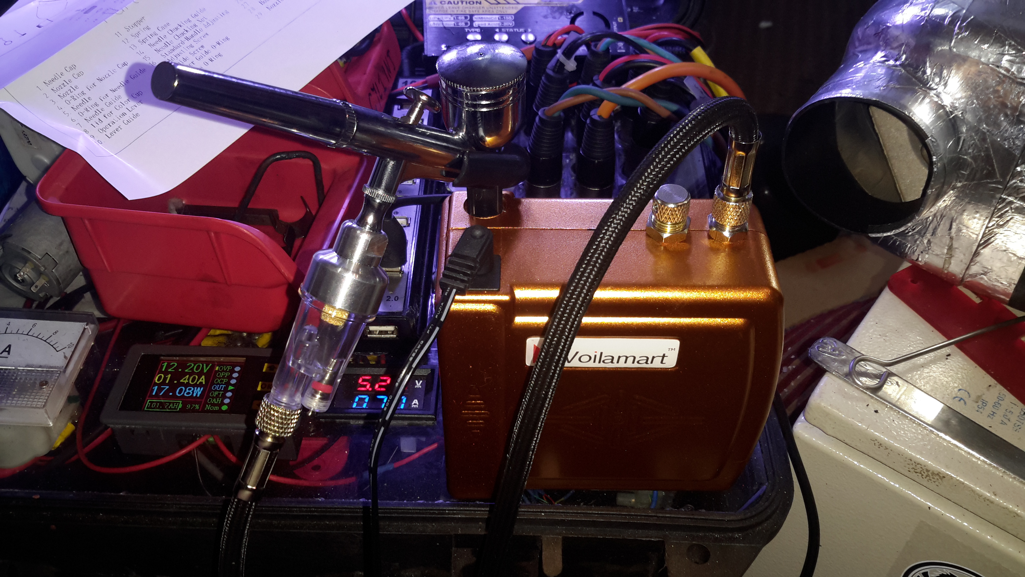
For my latest project, I needed an easier way to paint without messing about with brushes, and the associated marks they leave in a paint job. eBay provided me with a cheap airbrush & compressor.
Airbrush Kit
For less than £30, this kit doens’t look so bad. I’ve never used an airbrush before, but I’ve had no problems with this as yet spraying both water based paints & solvent based paints.
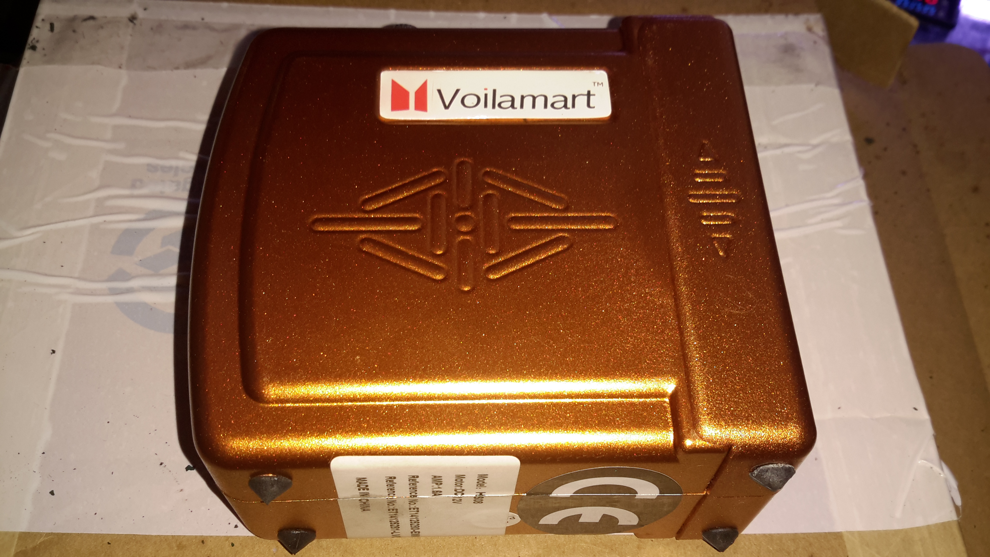
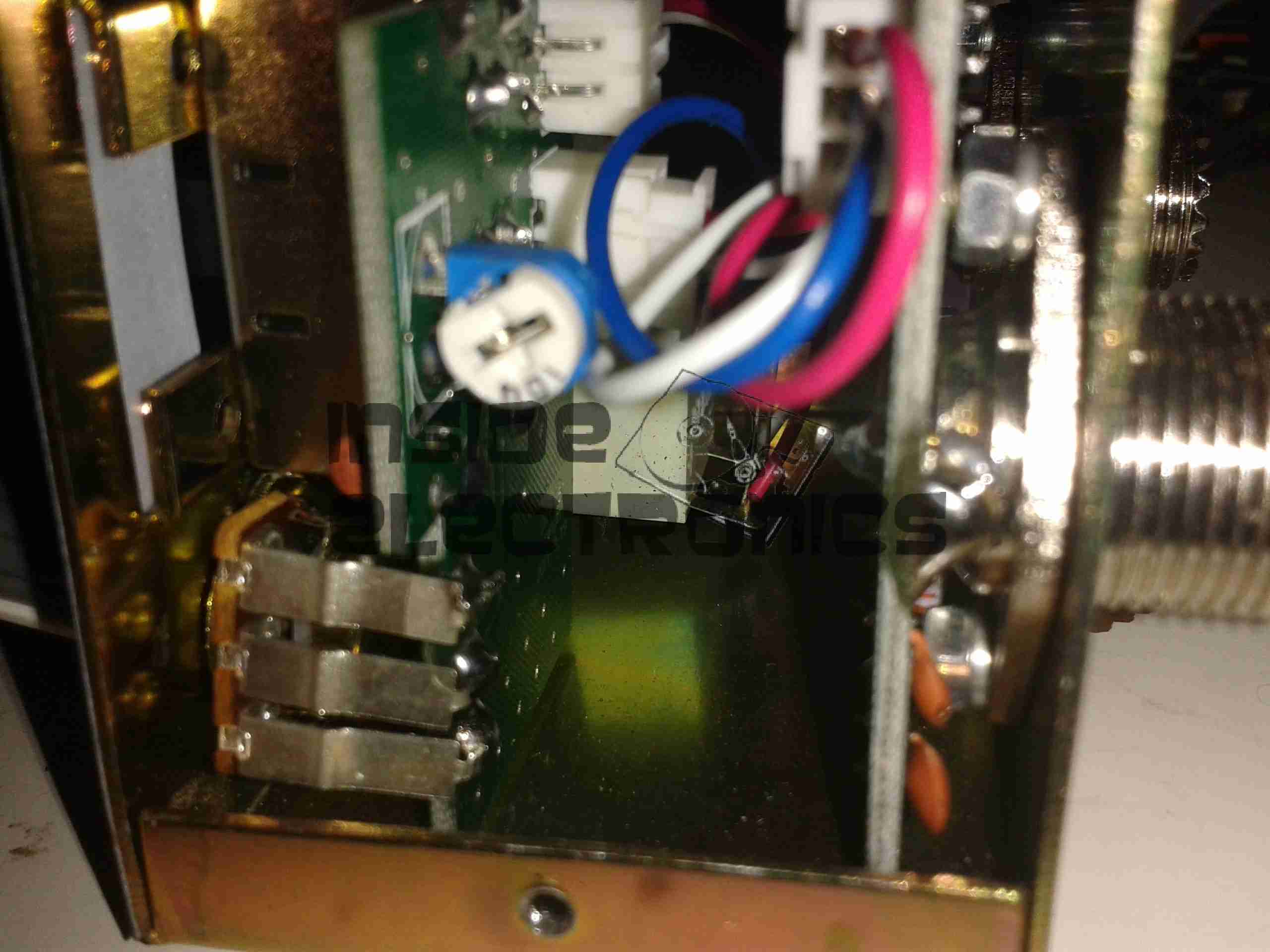
Compressor
Here’s the compressor itself, this runs on 12v & has an output pressure of 1.5 Bar, which is supposed to be adjustable.
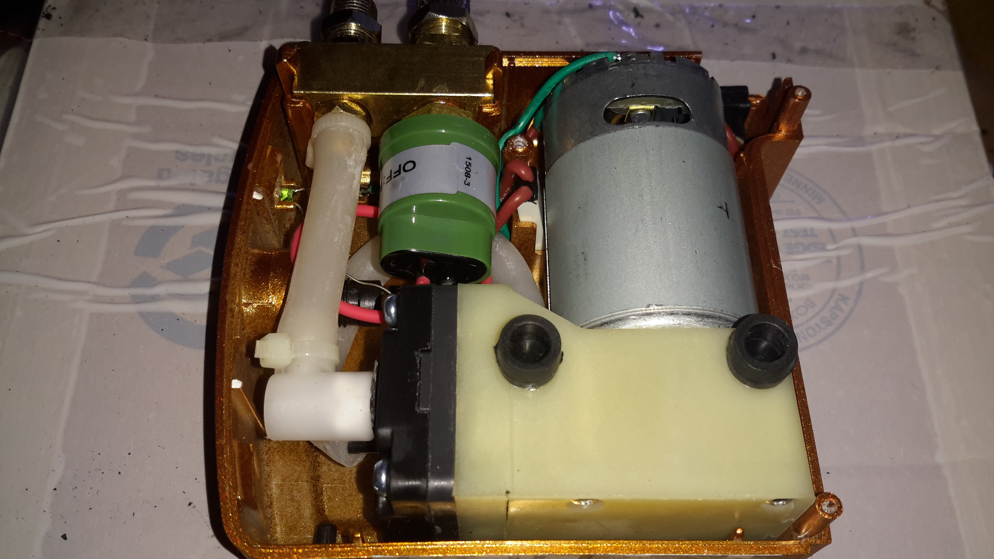
Compressor Internals
Removing a couple of screws reveals the internal components. Nothing much unusual here, a DC diaphragm pump, pressure switch & outlet fittings. There’s also a thermal cutout fitted next to the motor for protection.
The pressure switch attached to the manifold trips at 1.5Bar, keeping the pressure to the brush pretty much constant.
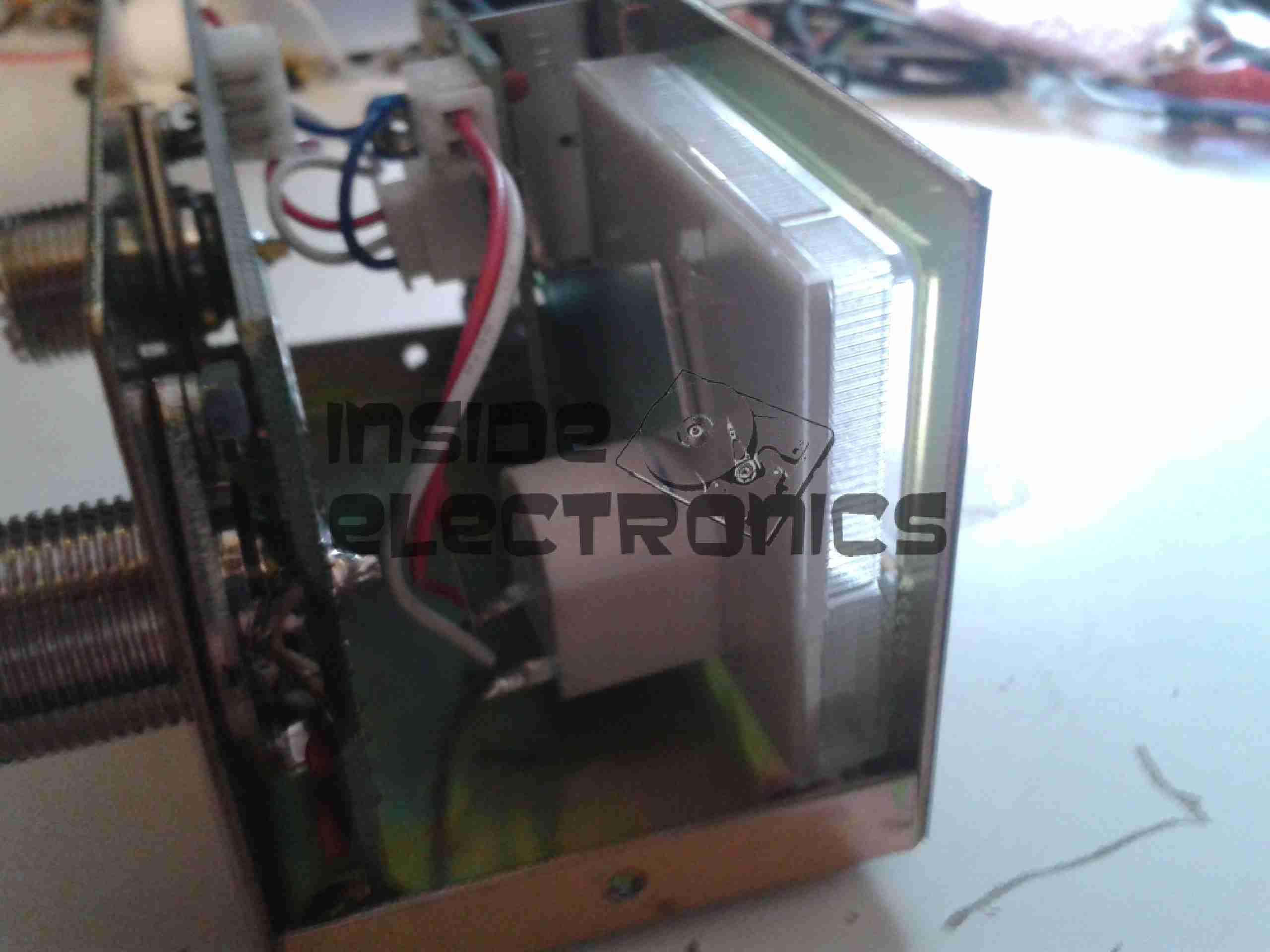
Air Block
Next to the air outlet fitting is an adjustment knob, supposedly for varying the pressure. However it’s just a piss-poorly designed adjustable relief valve that vents to atmosphere. There’s not much of a control range.
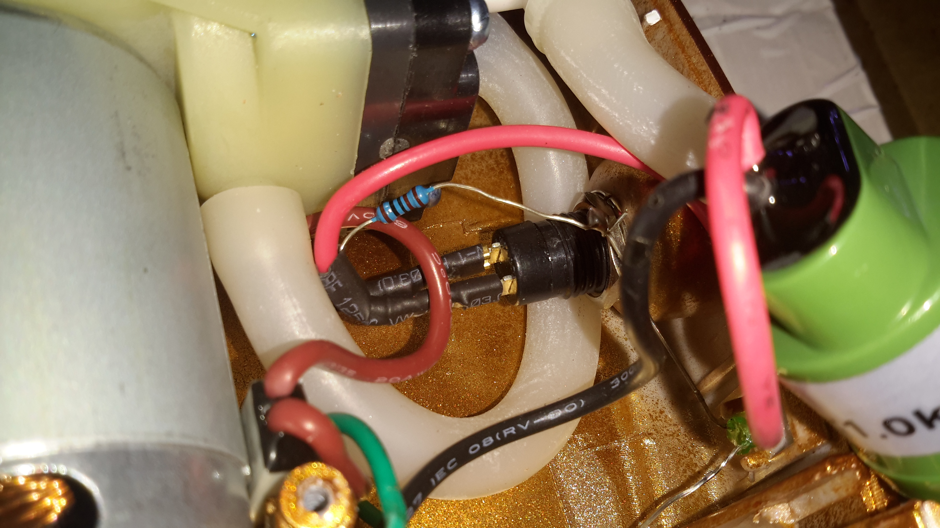
Messy Wiring
The wiring gets a bit messy where the power LED is concerned, with no heatshrink over the solder joints, but it’s adequate.
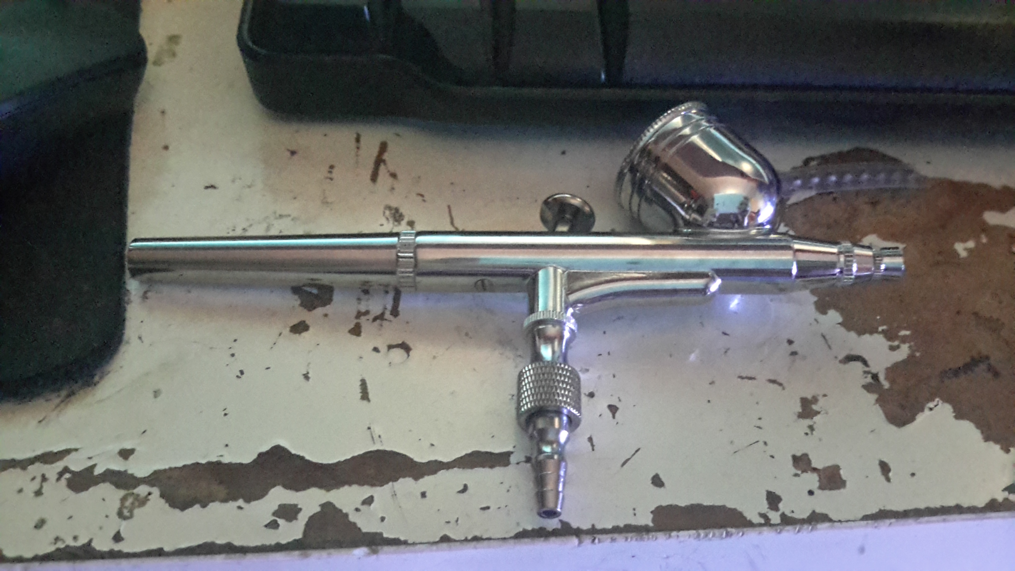
Airbrush
The airbrush itself isn’t too bad. It’s solid Brass, with a very nice Chrome finish. I’m not expecting miracles from a very cheap tool, but it certainly seems to be reasonable.
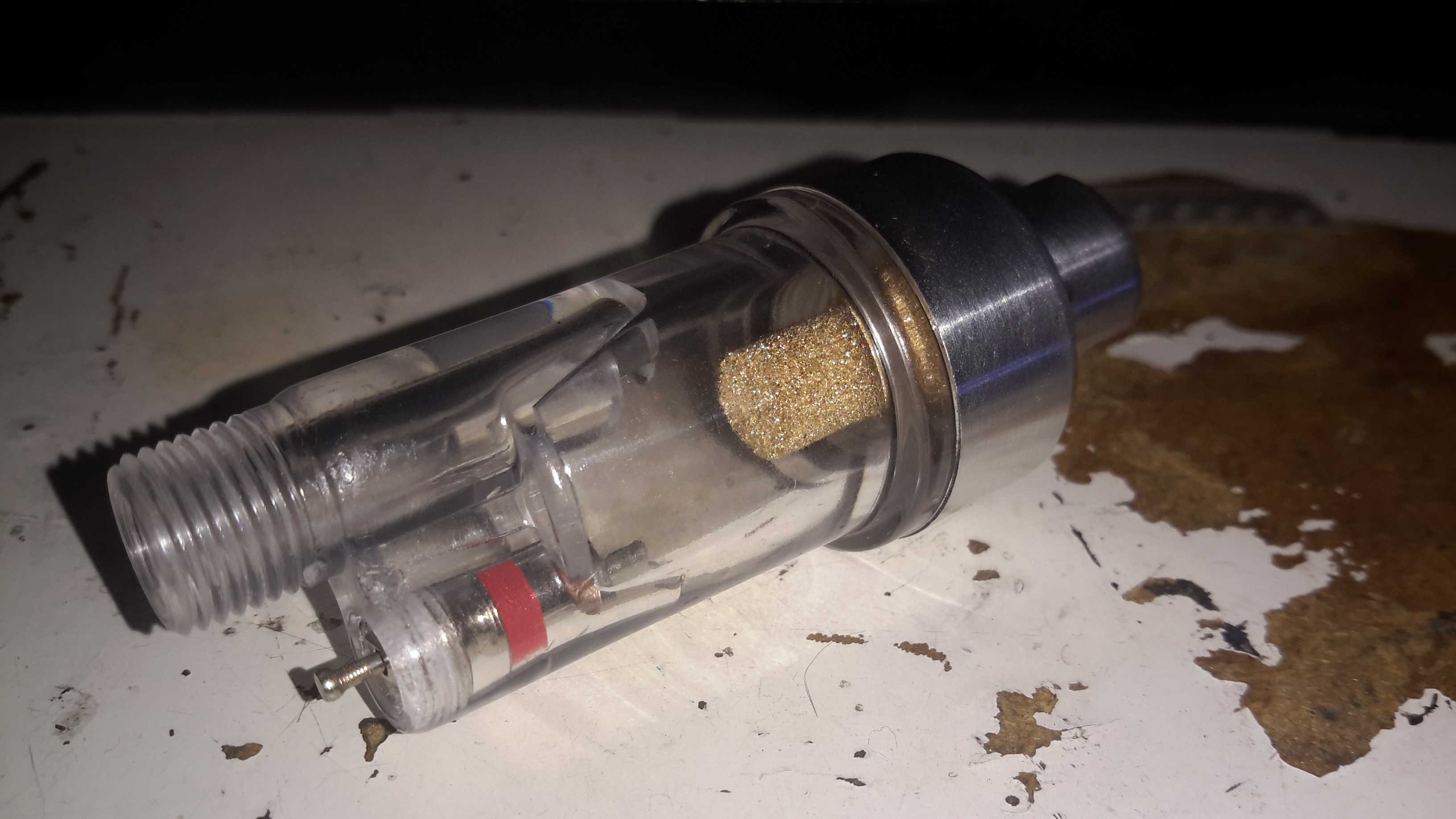
Water Trap
A moisture trap is supplied for the brush, to prevent water drops being sprayed out with the paint. Very handy.
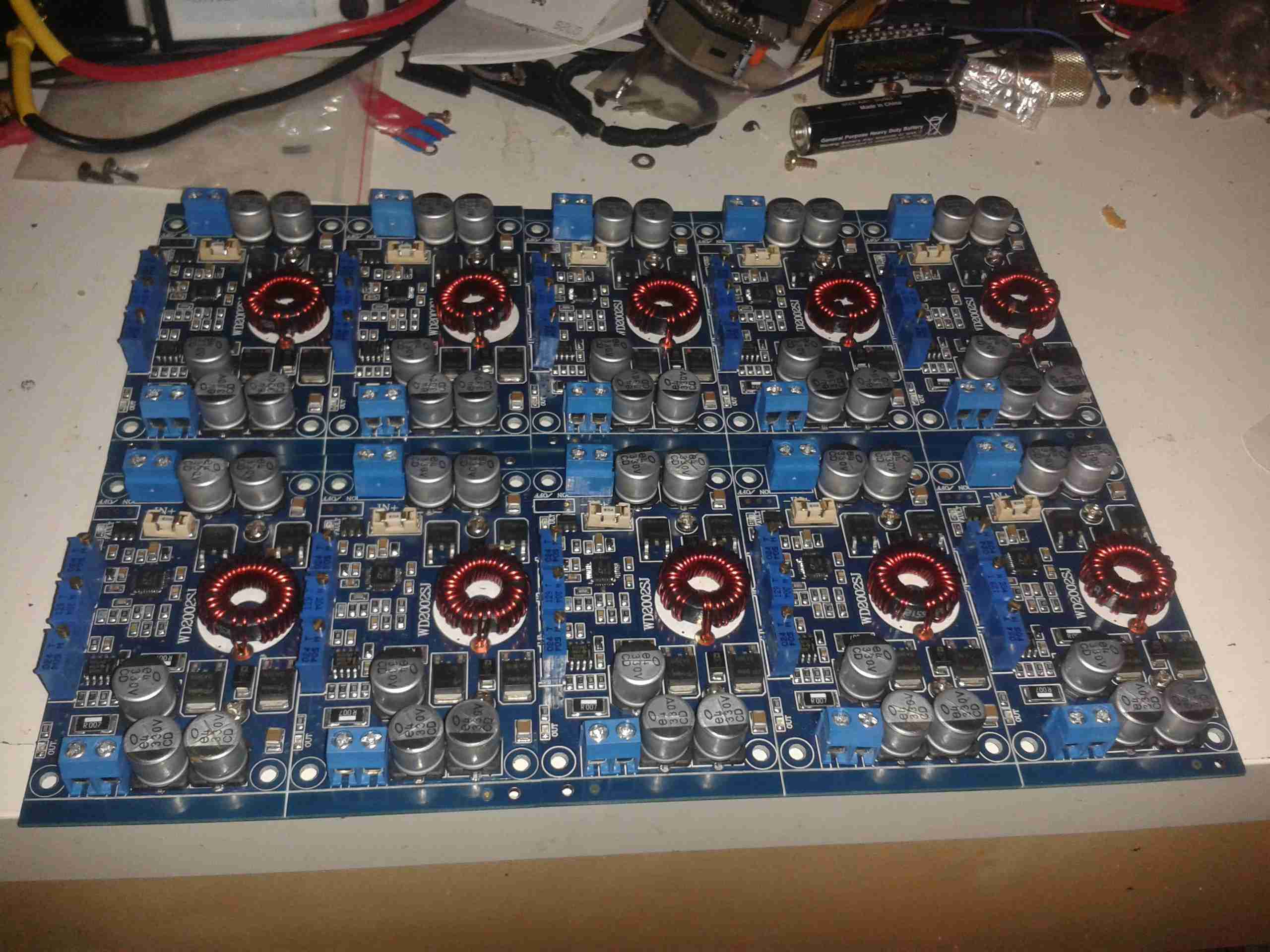
The power supplies I have recently built from surplus Cisco switch boards have started displaying a rather irritating problem – continual load of over 9A causes the supplies to shut down on overheat.
This was partially expected, as the original switches that these supplies came from are cooled by a monster of a centrifugal blower that could give a Dyson a run for it’s money. The problem with these fans is that they’re very loud, draw a lot of power (3-4A) and aren’t small enough to fit into the case I’ve used for the project.
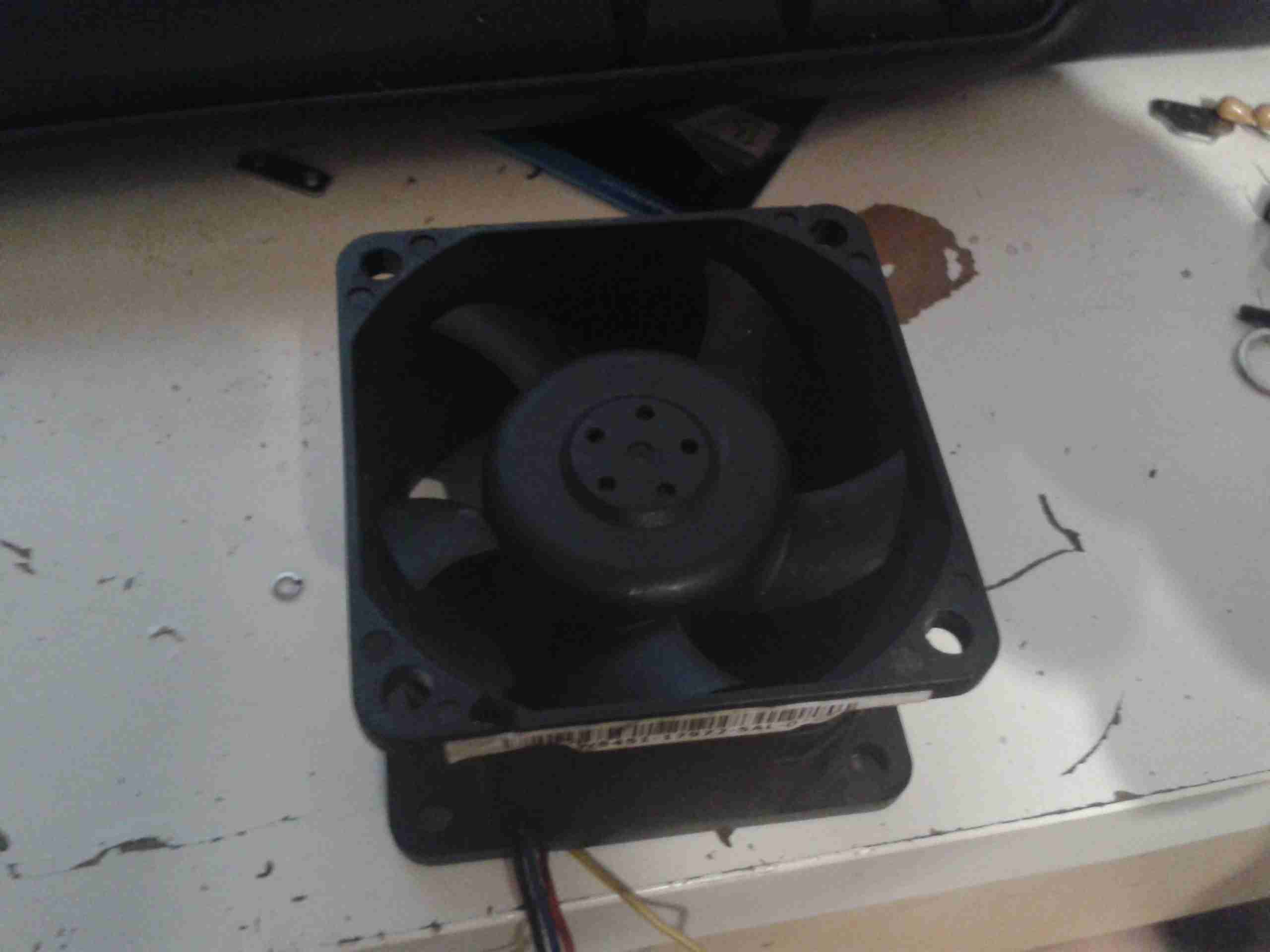
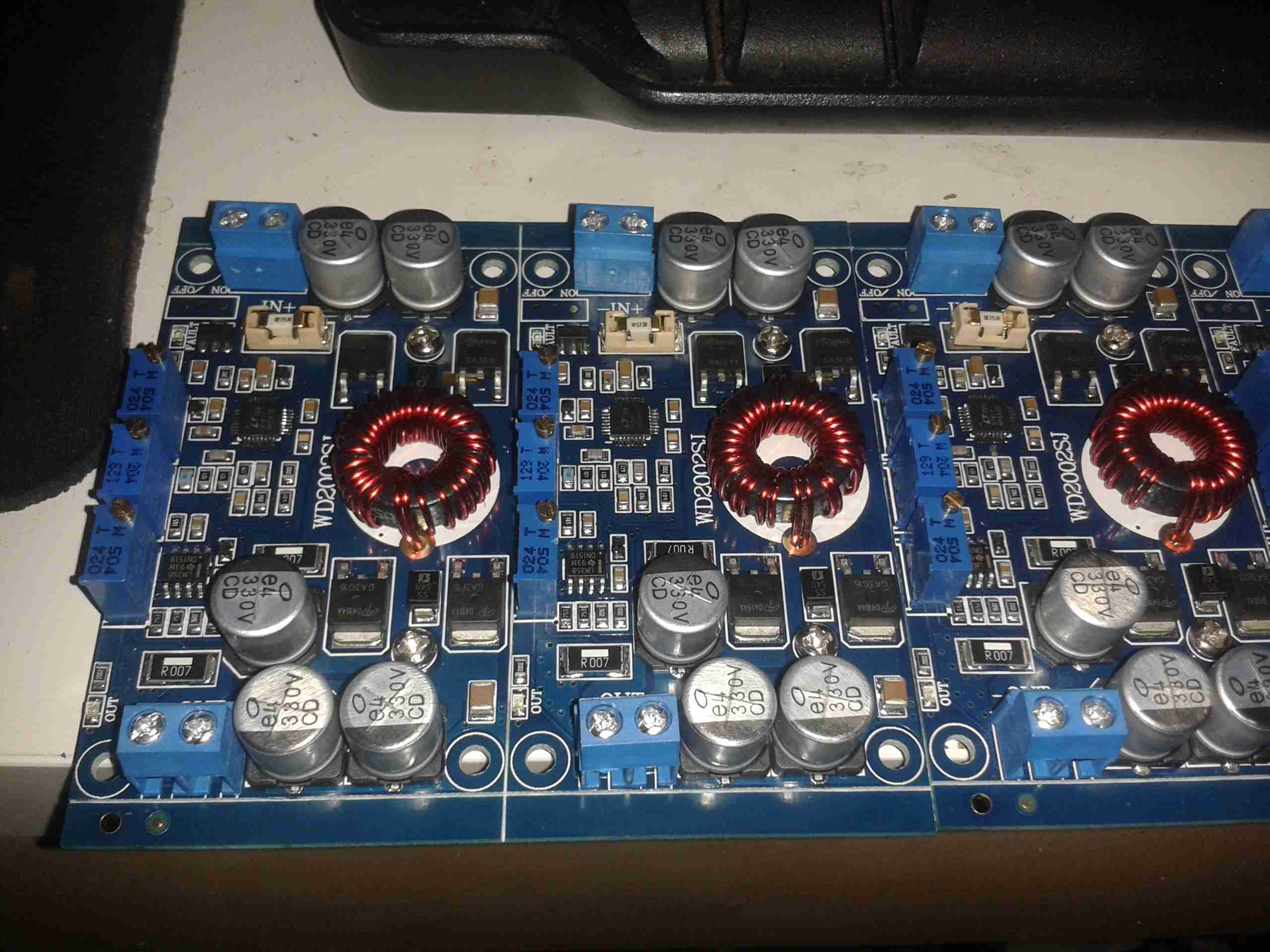
The solution of course, is a bigger fan – I’ve got some Delta AFB0612EHE server fans, these are very powerful axial units, shifting 60CFM at 11,000RPM, with a power draw of 1.12A.
They’re 60mm diameter, so only just fit into the back of the case – although they stick out of the back by 40mm.
Monster Fan
Here’s the fan, not the beefiest I have, but the beefiest that will fit into the available space.
These will easily take fingers off if they get too close at full speed, so guards will definitely be required.
To reduce the noise (they sound like jet engines at full pelt), I have ordered some PWM controllers that have a temperature sensor onboard, so I can have the fan run at a speed proportional to the PSU temperature. I will probably attach the sensor to the output rectifier heatsink, since that’s got the highest thermal load for it’s size.
I recently posted about a small analog SWR/Power meter I got from eBay, and figured it needed some improvement.
After some web searching I located a project by ON7EQ, an Arduino sketch to read SWR & RF power from any SWR bridge.
The Arduino code is on the original author’s page above, his copyright restrictions forbid me to reproduce it here.
I have also noticed a small glitch in the code when it is flashed to a blank arduino: The display will show scrambled characters as if it has crashed. However pushing the buttons a few times & rebooting the Arduino seems to fix this. I think it’s related to the EEPROM being blank on a new Arduino board.
I have run a board up in Eagle for testing, shown below is the layout:
SWR Meter SCH
The Schematic is the same as is given on ON7EQ’s site. Update: ON7EQ has kindly let me know I’ve mixed up R6 & R7, so make sure they’re switched round when the board is built ;). Fitting the resistors the wrong way around may damage the µC with overvoltage.
SWR Meter PCB
Here’s the PCB layout. I’ve kept it as simple as possible with only a single link on the top side of the board.
PCB Top
Here’s the freshly completed PCB ready to rock. Arduino Pro mini sits in the center doing all the work.
The link over to A5 on the arduino can be seen here, this allows the code to detect the supply voltage, useful for battery operation.
On the right hand edge of the PCB are the pair of SMA connectors to interface with the SWR bridge. Some RF filtering is provided on the inputs.
PCB Bottom
Trackside view of the PCB. This was etched using my tweaked toner transfer method.
LCD Fitted
Here the board has it’s 16×2 LCD module.
Online
Board powered & working. Here it’s set to the 70cm band. The pair of buttons on the bottom edge of the board change bands & operating modes.
As usual, the Eagle layout files are available below, along with the libraries I use.
[download id=”5585″]
[download id=”5573″]
More to come on this when some components arrive to interface this board with the SWR bridge in the eBay meter.
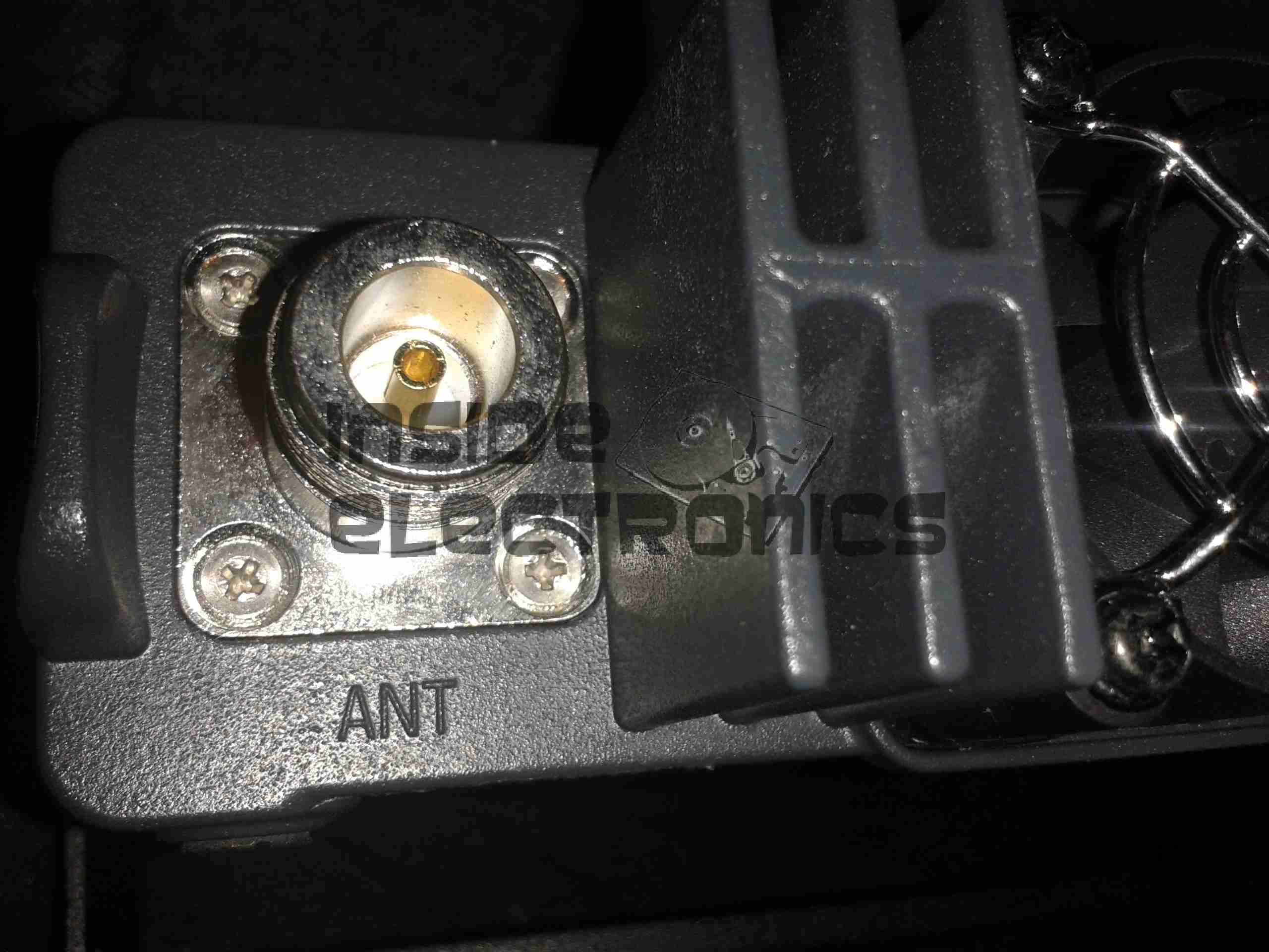
In my original review, I noted that this radio was supplied with a SO-259 socket for the antenna connection.
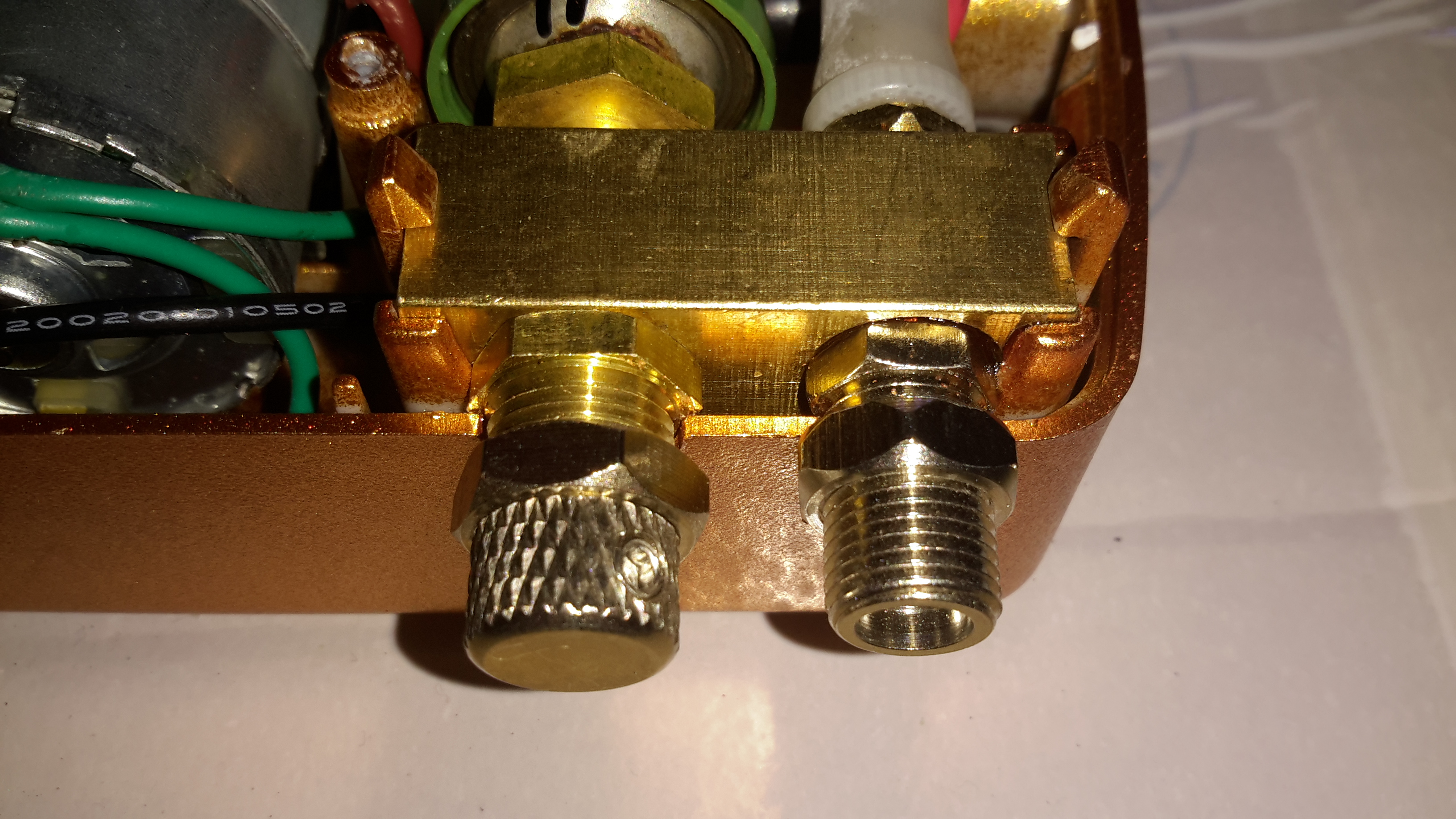
However I’m less than fond of these, due to their non-constant impedance, which can cause signal loss issues at VHF/UHF. Because of this, I’ve replaced it with a high quality N-type connector. These connectors are much better, as they are a constant 50Ω impedance, they’re weather resistant, and being rated to 11GHz, are more than sufficient for a radio that will only do up to 70cm.
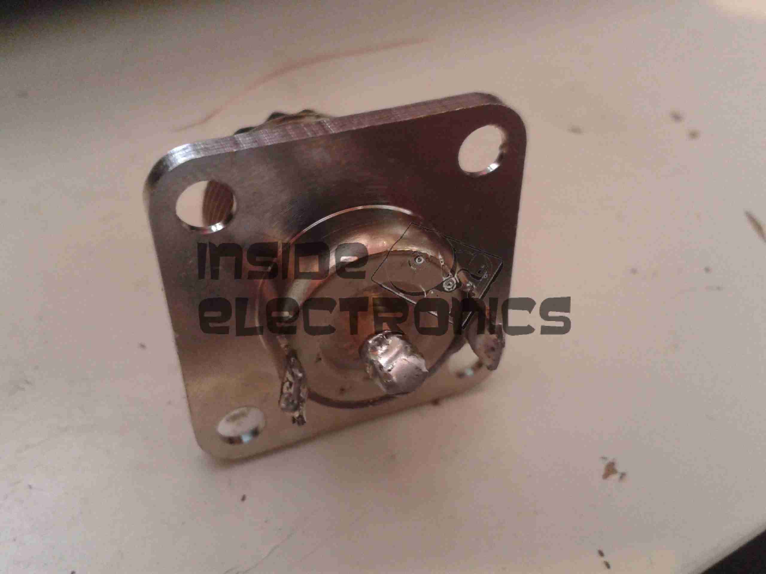
RF Output Jack
Here can be seen the point where the connection is made to the PCB.
I’ve already replaced the socket in this photo. The pair of solder pads either side of the central RF point were soldered to wings on the back of the original SO-259. As there are a pair of screws, also connected to the ground plane, there have been no signal issues with just using the frame of the radio as the ground point. Shown below is the original socket, with the ground wings.
Original SO-259
Finally, here is the back of the radio with it’s shiny new N connector.
New Connection
Chassis mount connectors are pretty standard, so this new connector fits perfectly into the same recess of the original. Looks like factory fitted!
I am now standardising on N connectors for everything in my radio shack, next on the project list for conversion is the SWR meter I recently acquired.
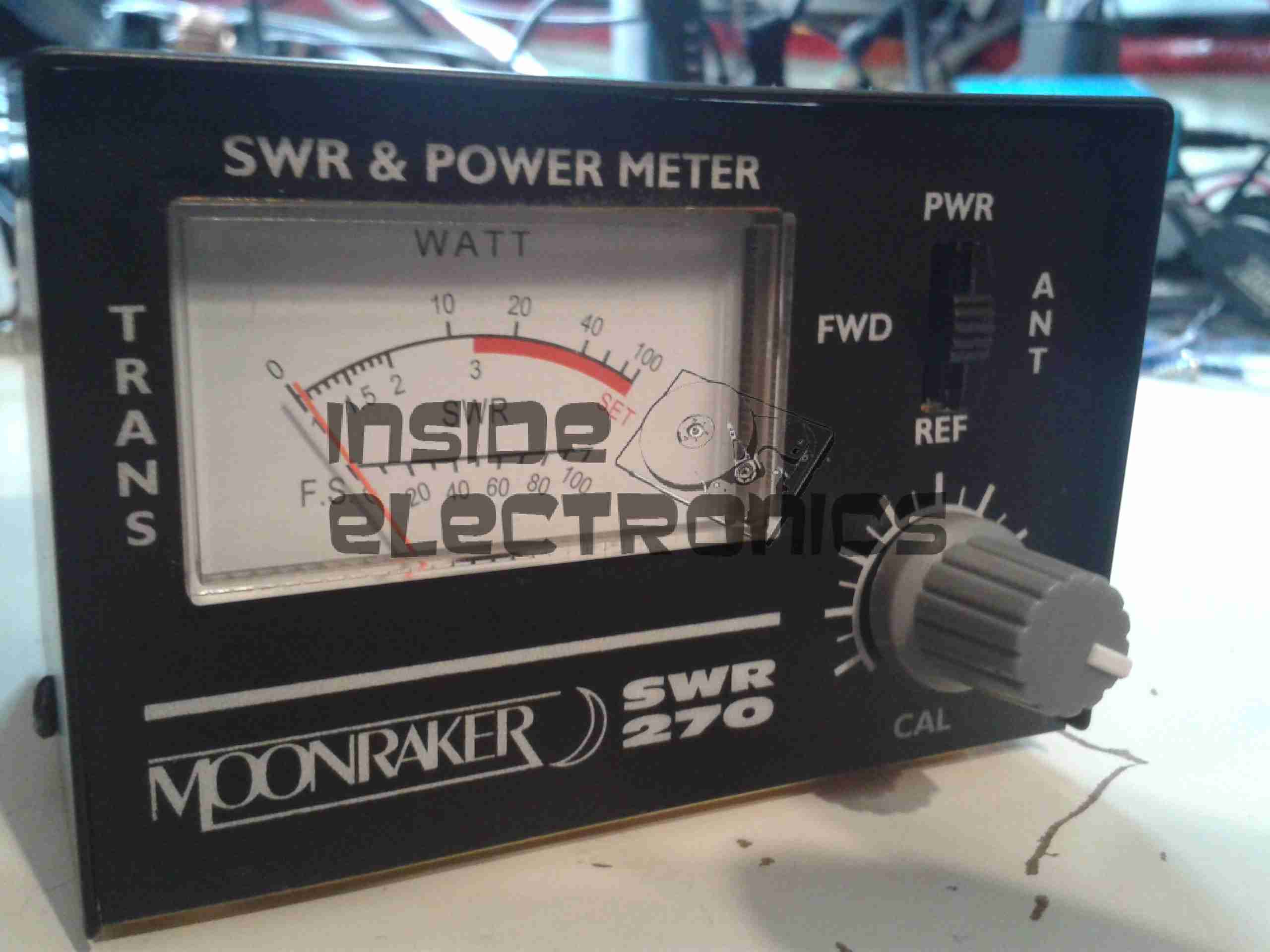
As I’m building up my radio shack, I figured an SWR meter would be a handy addition to my arsenal. This is a cheap Moonraker brand meter, which also will measure RF power. Above the front of the meter is shown, with the moving coil meter movement on the left, calibration adjustment on the right & the forward/reverse power switch.
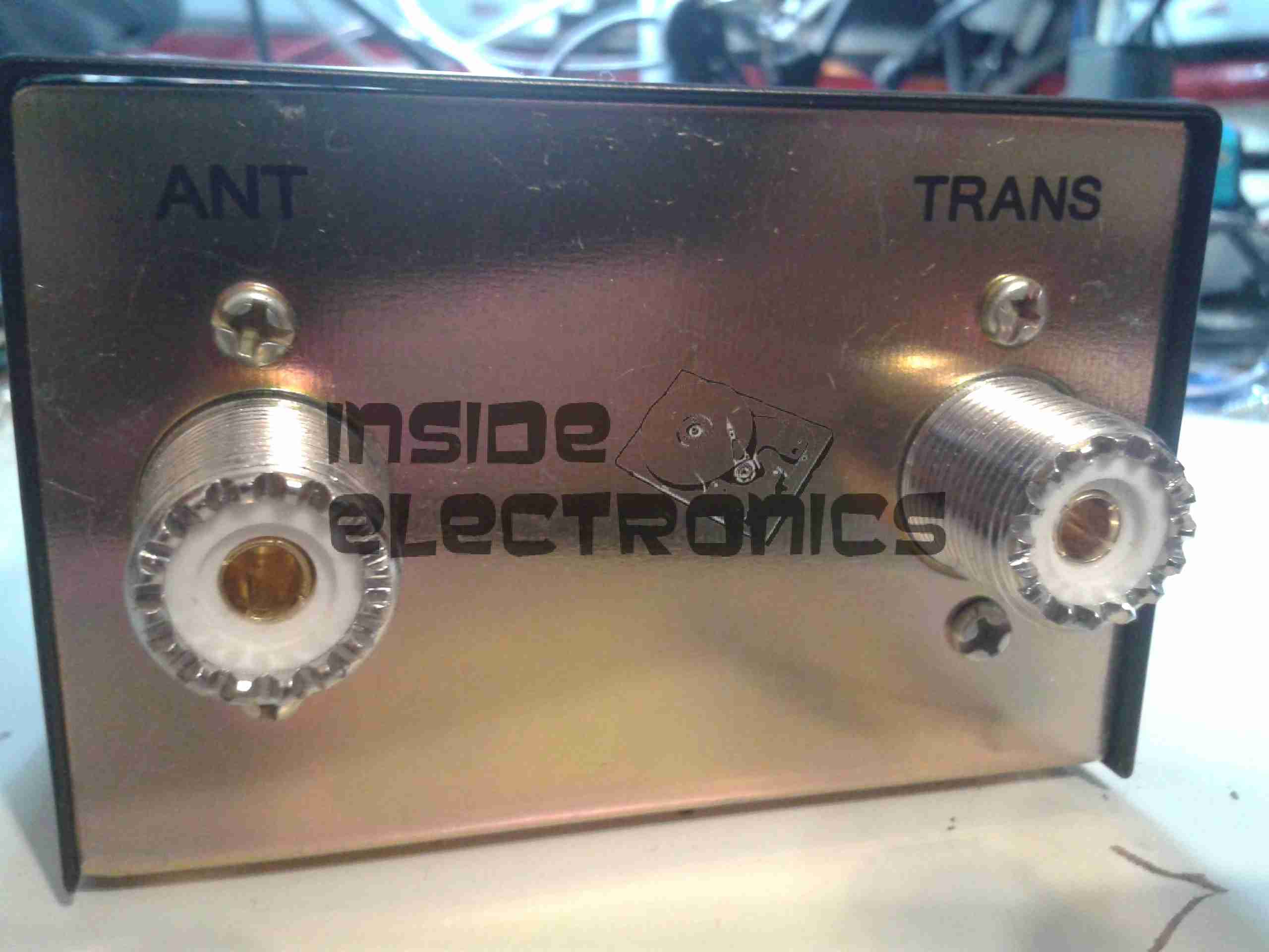
Meter Rear
For connections, standard SO-259 jacks are provided. The casing is sturdy 1mm steel. This is good, considering it’ll probably take a beating in my portable radio bag.
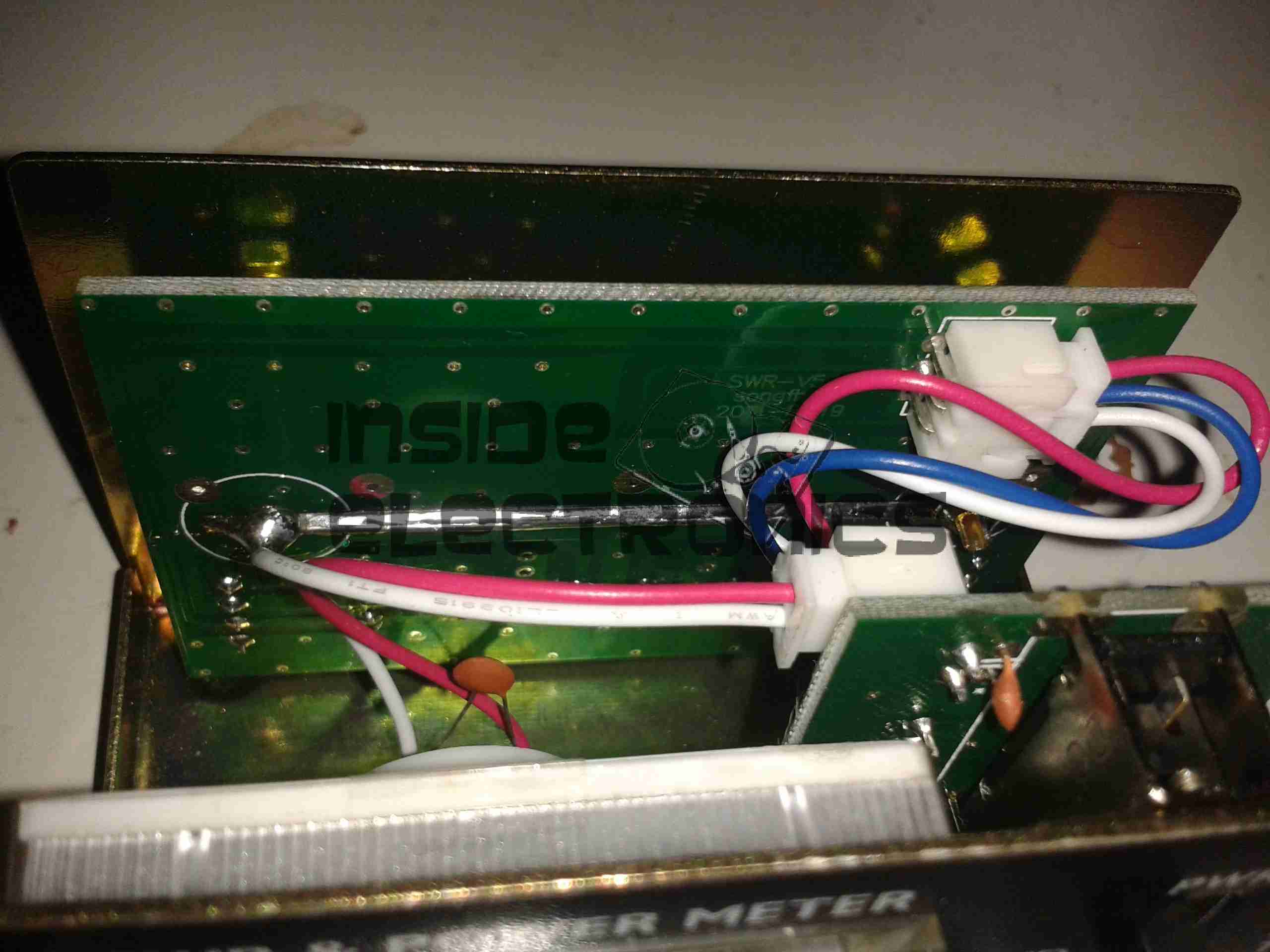
Directional Coupler PCB
Here the cover is removed, showing some of the internals. The large PCB across the back is the directional coupler.
Directional Coupler Circuit
The SO-259 connectors are bridged with a transmission line, (the track covered in solder in the image below), while there are a pair of sense lines running alongside. This main line is electromagnetically coupled to the two smaller sense lines, which are terminated at one end with resistors, with diodes at the other to rectify the coupled signal.
The termination resistors are sized to match the impedance of the sense lines.
The diodes, having rectified the coupled RF, produce DC voltages representing the value of the forward & reverse RF power. These DC voltages are smoothed with the capacitors.
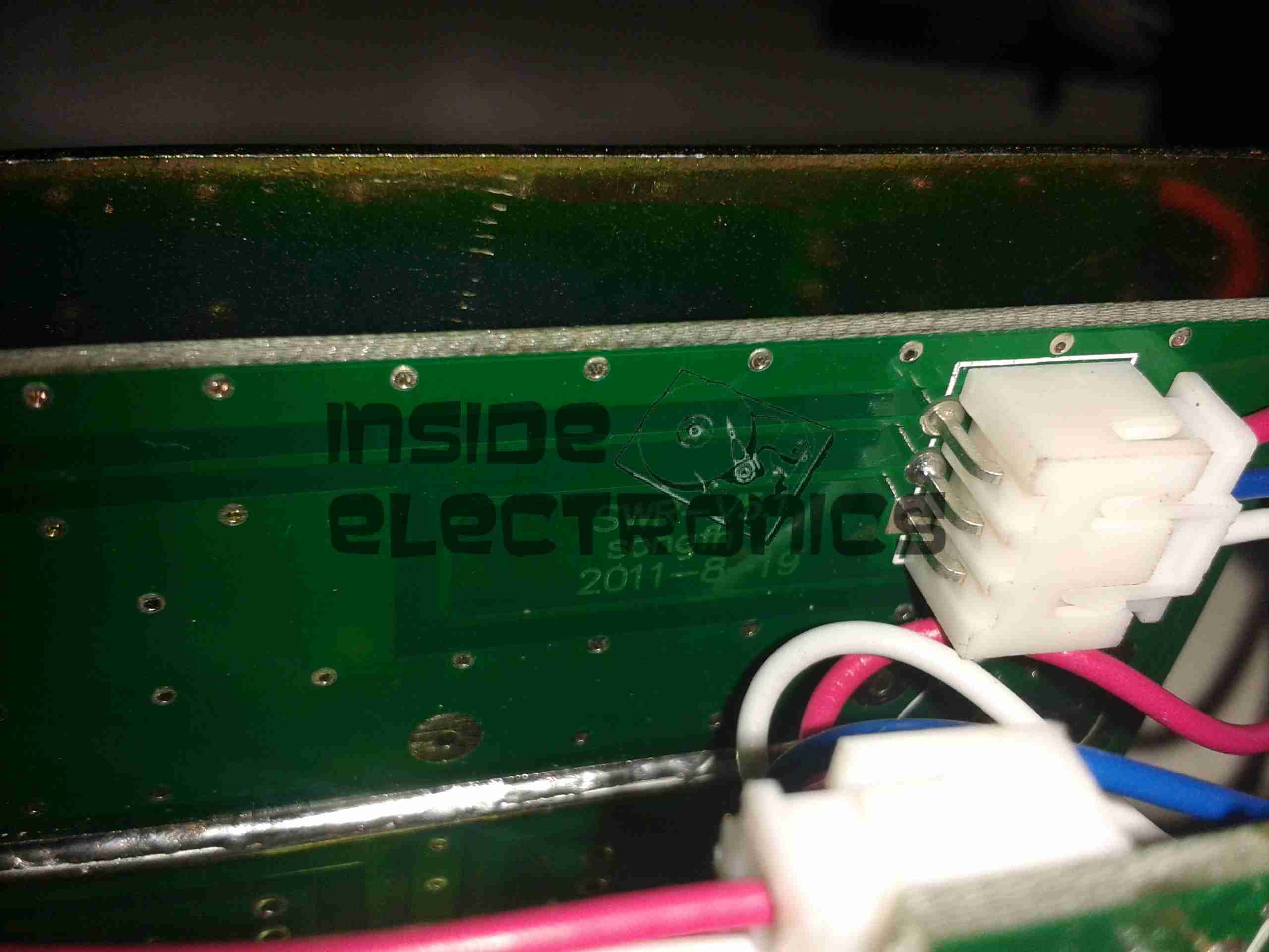
PCB Marking
The PCB is dated 19-8-2011, so it’s a fairly old design.
Adjustments
Here is visible the back of the user calibration adjuster, with the factory calibration trimmer.
Meter Movement
Back of the meter movement. This is a standard moving coil type. Nothing special.
This meter will soon be modified to accept connection of an external Arduino-based SWR & power meter, which I can calibrate individually for each band.
Stay tuned for that upcoming project.
Continuing from my previous post where I published an Eagle design layout for AD7C‘s Arduino powered VFO, here is a completed board.
I have made some alterations to the design since posting, which are reflected in the artwork download in that post, mainly due to Eagle having a slight psychotic episode making me ground one of the display control signals!
AD9850 VFO
The amplifier section is unpopulated & bypassed as I was getting some bad distortion effects from that section, some more work is needed there.
The Arduino Pro Mini is situated under the display, and the 5v rail is provided by the LM7805 on the lower left corner.
Current draw at 12v input is 150mA, for a power of 1.8W total. About 1W of this is dissipated in the LM7805 regulator, so I have also done a layout with an LM2574 Switching Regulator.
The SMPS version should draw a lot let power, as less is being dissipated in the power supply, but this version is more complex.
DDS VFO-SMPS
Here the SMPS circuit can be seen on the left hand side of the board, completely replacing the linear regulator.
I have not yet built this design, so I don’t know what kind of effect this will have on the output signal, versus the linear regulator. I have a feeling that the switching frequency of the LM2574 (52kHz) might produce some interference on the output of the DDS module. However I have designed this section to the standards in the datasheet, so this should be minimal.
Nevertheless this version is included in the Downloads section at the bottom of this post.
The output coupled through a 100nF capacitor is very clean, as can be seen below, outputting a 1kHz signal. Oscilloscope scale is 0.5ms/div & 1V/div.
VFO Output (Mucky ‘Scope)Scope Connected
Thanks again to Rich over at AD7C for the very useful tool design!
Linked below is the Eagle design files for this project, along with my libraries used to create it.
The quickest project from inception to working PCB yet:
From inception to a working PCB took only 4 hours!
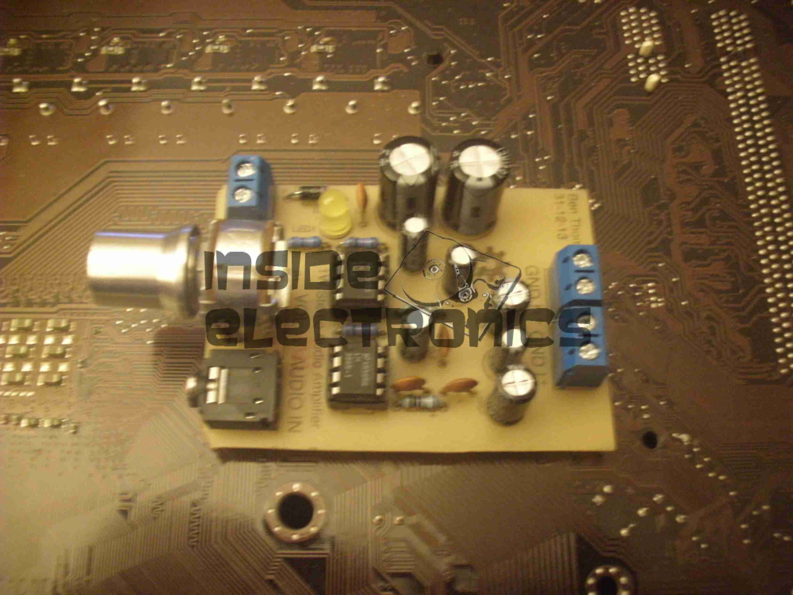
LM386 Amplifier
This is a miniature stereo audio amplifier, 0.5W per channel, that can be run from any voltage between 4-12v DC.
As usual, all the Eagle project files are available for download below & kits/bare PCBs will be available for sale for those that cannot etch boards.
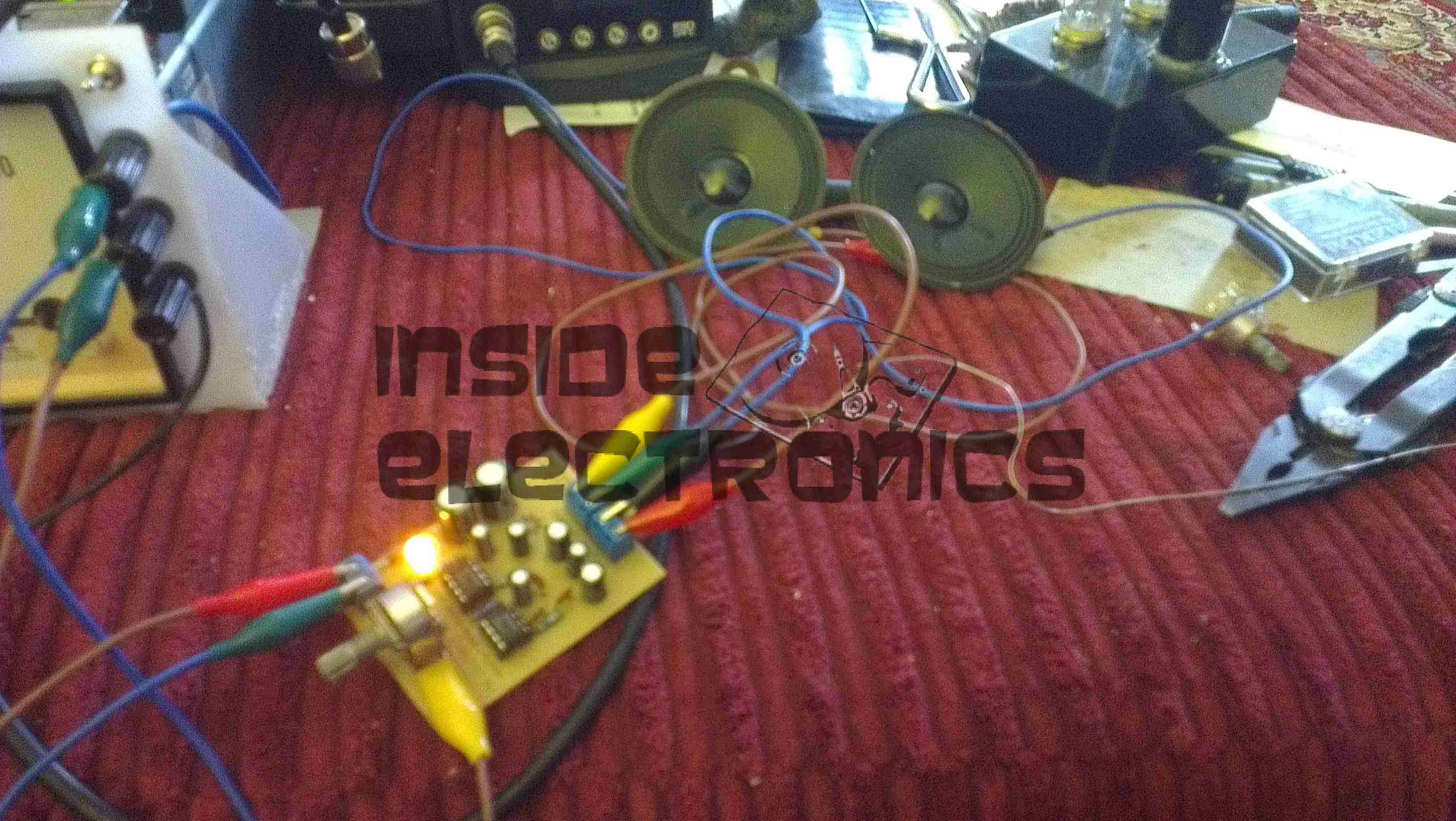
In Operation
Here is the circuit driving a pair of 3W 8Ω speakers from a line level audio source. The gain of this circuit is set at 50 with the components specified.
Schematic
As can be seen from the schematic, this is a pair of single LM386 ICs for each channel.
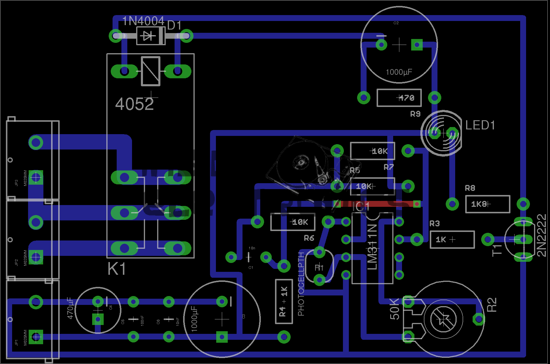
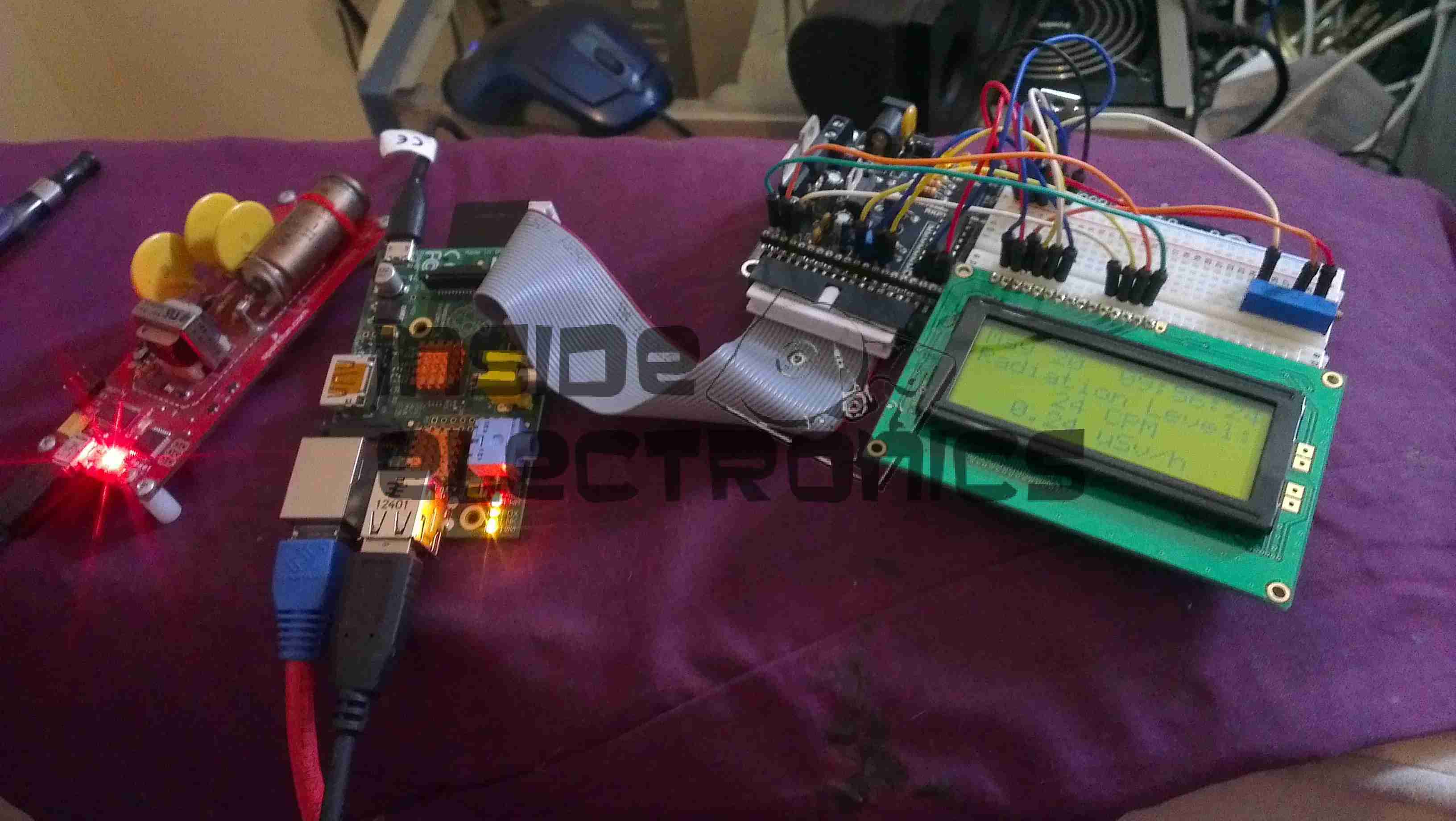
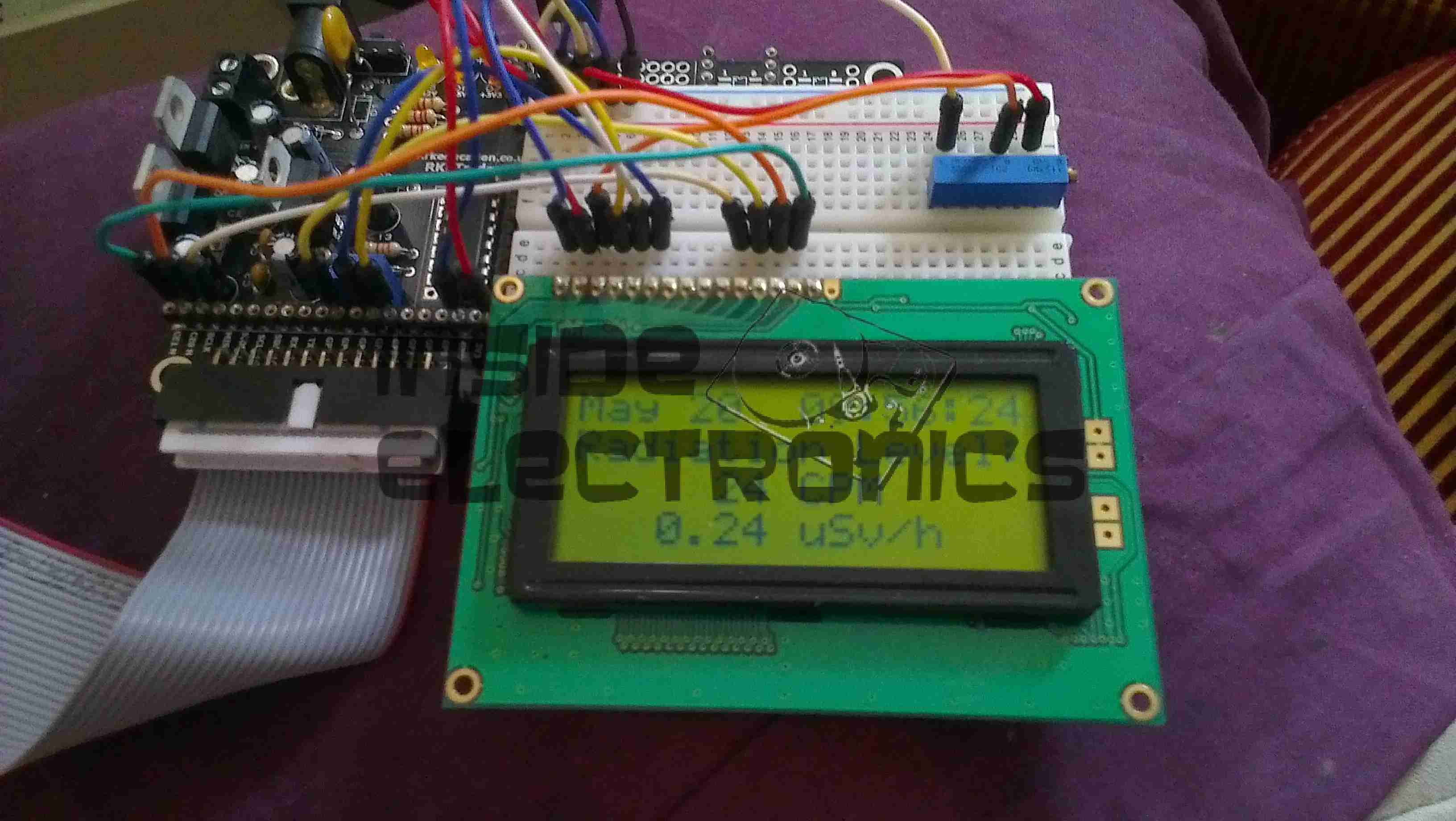
Here’s my latest project with the Pi: interfacing it with the Sparkfun Geiger counter & outputting the resulting data to a character LCD.
The geiger counter is interfaced with it’s USB port, with the random number generator firmware. A Python script reads from the serial port & every minute outputs CPM & µSv/h data to the display.
The Python code is a mash of a few different projects I found online, for different geiger counters & some of my own customisations & code to write the info to the display & convert CPM into µSv/h.
This also writes all the data into a file at /var/log/radlog.txt
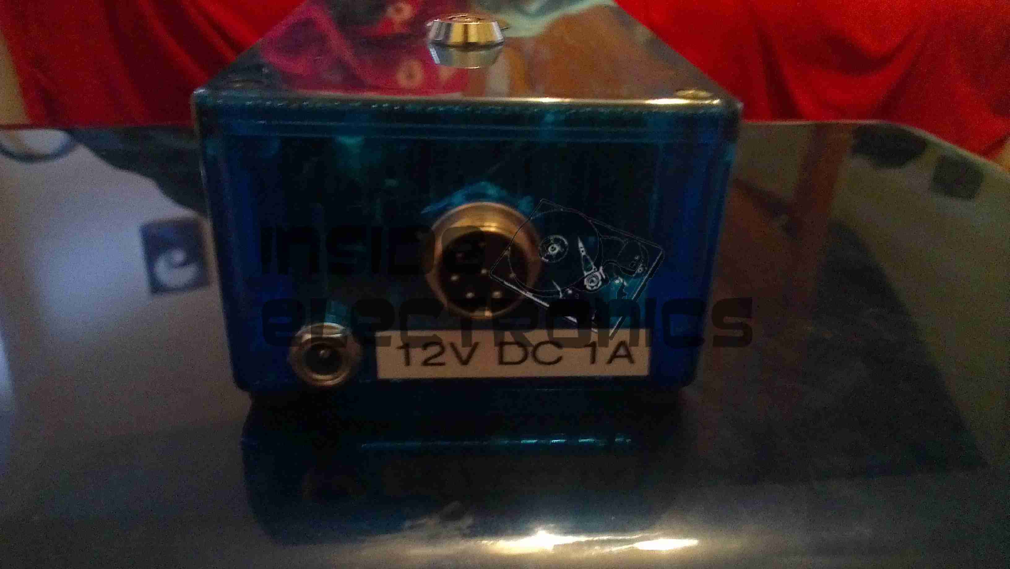
In preparation for my laser scanner project, I have modified my existing 445nm laser to accept a TTL blanking input. The laser driver is already enabled for this & just required an extra connection to interface with my laser scanner showboard. I have used an 8-pin connection to allow the same cable & interface to be used with an RGB laser system, when it arrives. The signals are as follows, from top centre, anti-clockwise:
Pin 1: +12v Power
Pin 2: Blue TTL
Pin3: GND
Pin 4: Green TTL
Pin 5: GND
Pin 6: Red TTL
Pin 7: GND
Centre: Power GND
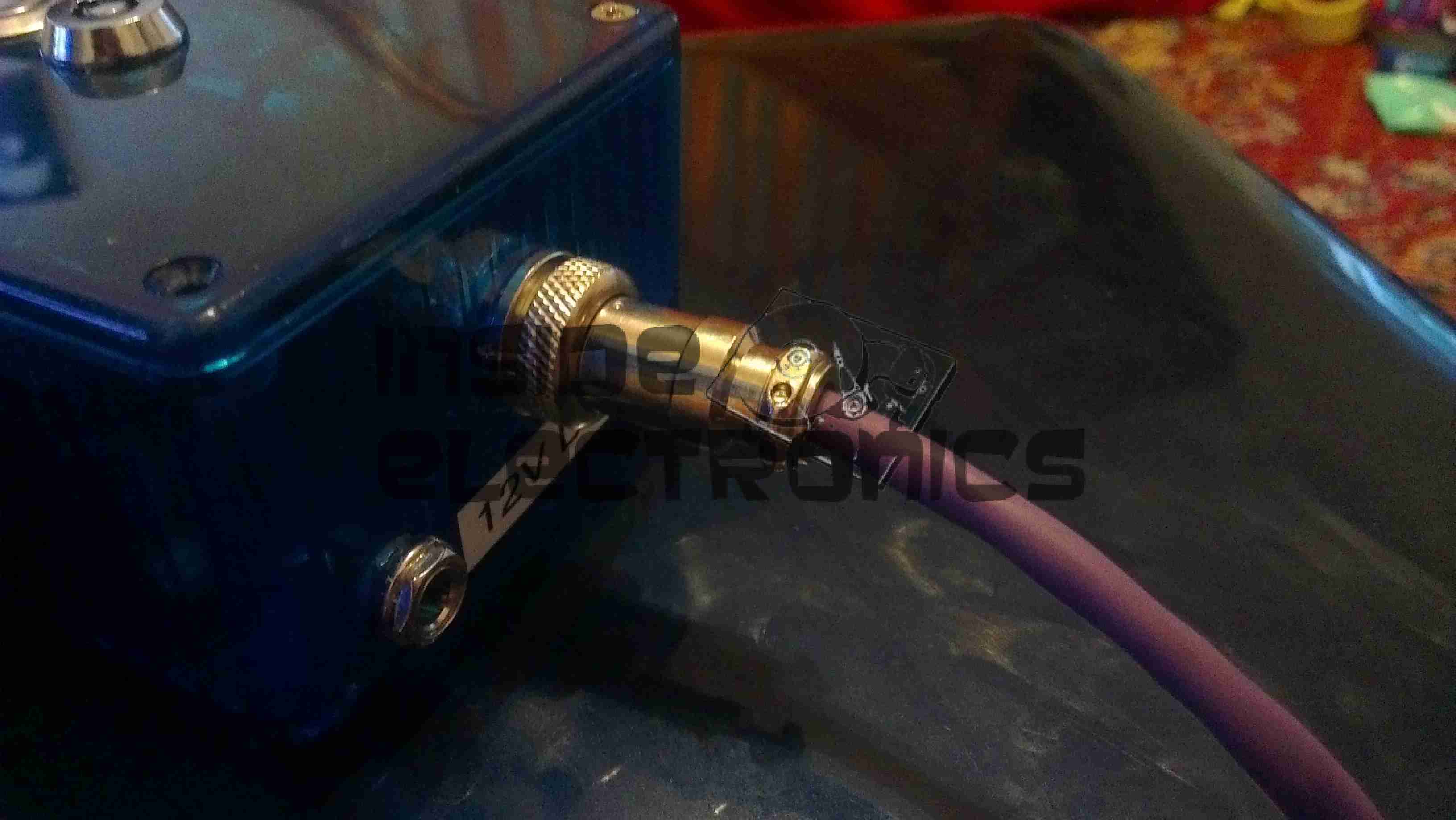
Custom TTL Cable
Here is the custom 8 core cable, which connects to the laser scanner show board. This cable allows the laser to be used for projection while still retaining the portable function & the keylock arming switch. When plugged in the cable bypasses the keyswitch & provides 12v DC direct to the laser driver.
Here are a few details of a valve amplifier I am building, using the valve related parts from a 1960’s reel to reel tape recorder.
This amplifier is based on an a Mullard ECL82 triode/pentode valve, with an EM84 magic eye tube for level indication.
Beginnings Of The Amplifier
Here the first components are being soldered to the tags on the valve holder, there are so few components that a PCB is not required, everything can be rats-nested onto the valve holders.
Progress
Progressing with the amplifier section componentry, all resistors are either 1/2W or 2W.
Valve Sockets Fitted
Here the valve holders have been fitted, along with the output transformer, DC smoothing capacitor & the filament wiring, into the top of the plastic housing. At this point all the components that complete the amplifier section are soldered to the bottom of the right hand valve holder.
Wiring
Starting the wiring between the valves & the power supply components. The volume control pot is fitted between the valve holders.
Valves Test Fit
The valves here are test fitted into their sockets, the aluminium can at the back is a triple 32uF 250v electrolytic capacitor for smoothing the B+ rail.
Amplifier Section First Test
First test of the amplifier, with the speaker from the 1960’s tape recorder from which the valves came from. the 200v DC B+ supply & the 6.3v AC filament supply is derived from the mains transformer in the background.
Magic Eye Tube Added
Here the magic eye tube has been fitted & is getting it’s initial tuning to the amplifier section. This requires selecting combinations of anode & grid resistors to set the gap between the bars while at no signal & picking a coupling RC network to give the desired response curve.
Final Test
Here both valves are fitted & the unit is sitting on it’s case for final audio testing. the cathodes of the ECL82 can be clearly seen glowing dull red here.
In the final section, I will build a SMPS power supply into the unit to allow it to be powered from a single 12v DC power supply.
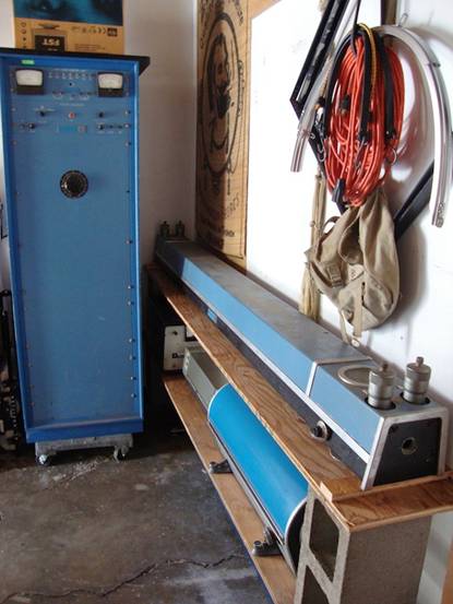
This is detailing my portable multi-purpose power pack of my own design. Here is an overview, mainly showing the 4Ah 12v Ni-Cd battery pack.
Front Panel Right
Panel Features – Bottom: Car cigar lighter socket, main power keyswitch. Top: LED toggle switch, provision for upcoming laser project, Red main Power LED, 7A circuit breaker.
Front Panel Left
Top: Toggle switch serving post terminals, USB Port.
Post terminals supply unregulated 12v for external gadgets. USB port is standard 5v regulated for charging phones, PDAs etc.
Bottom: Pair of XLR connectors for external LED lights. Switches on their right control power & the knob controls brightness.
Additions are being made to this all the time, the latest being a 2W laser diode driver. Update to come soon!
Tip Jar
If you’ve found my content useful, please consider leaving a donation by clicking the Tip Jar below!
All collected funds go towards new content & the costs of keeping the server online.