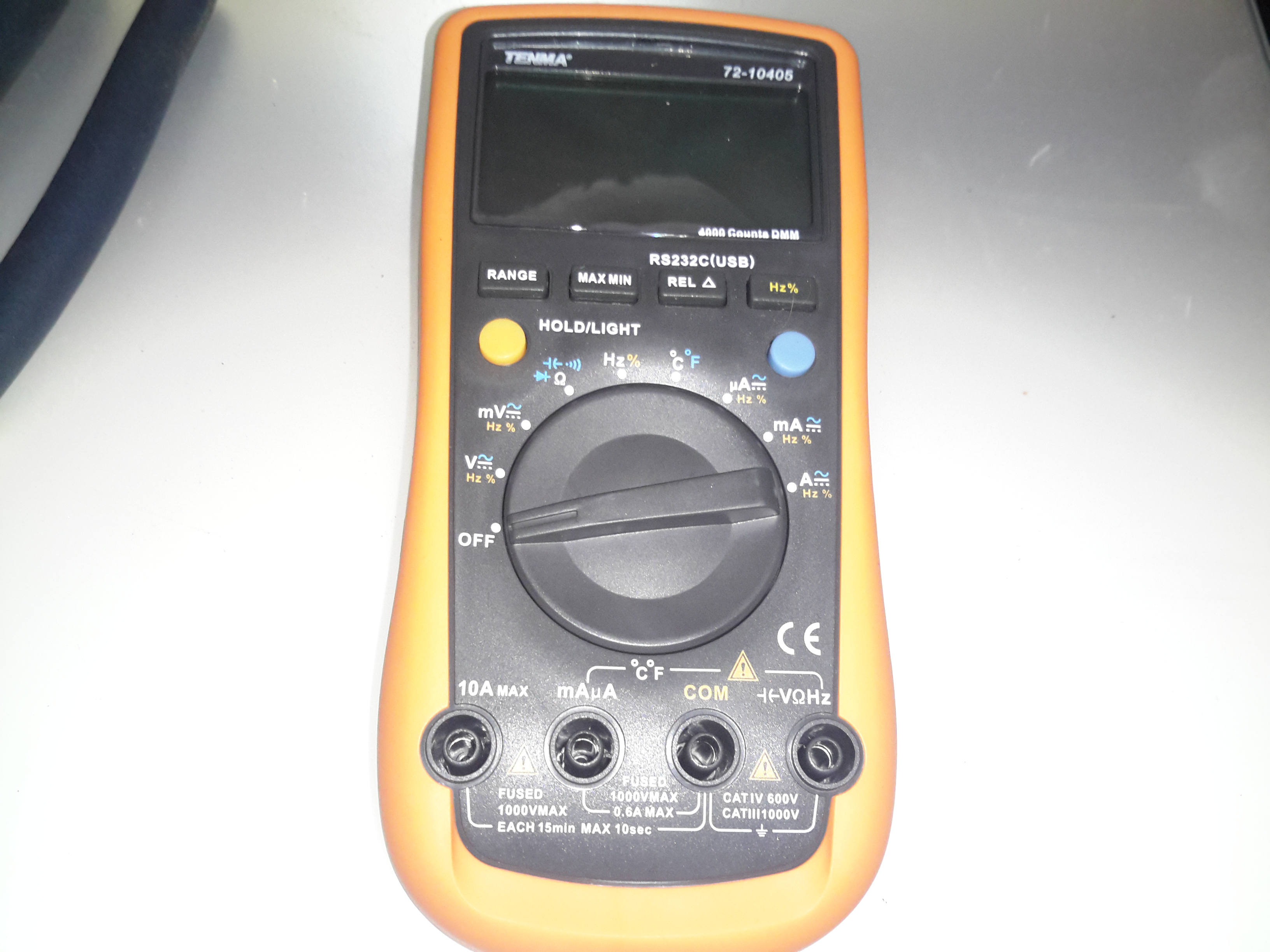
Well it’s time for a new DMM. After the last pair of eBay El-Cheapo Chinese meters just didn’t last very well, I decided a proper meter was required. This one is a Tenma 72-10405, stocked by Farnell for under £60. Not quite as many festures as the cheapo Chinese meters, but I expect this one to be a bit more reliable.
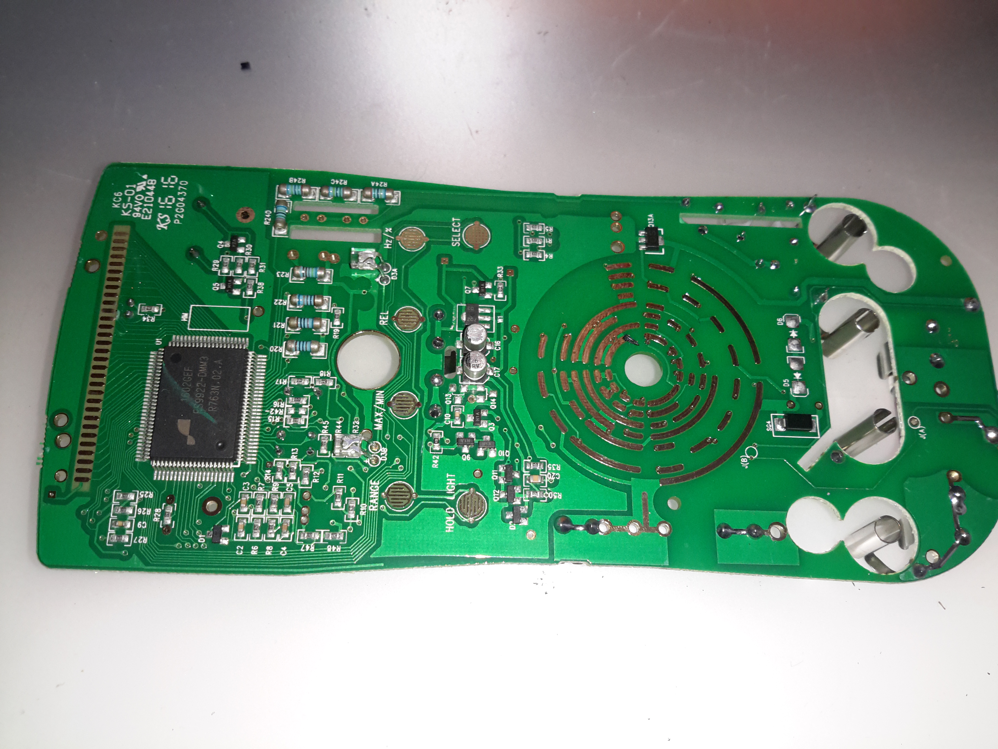
PCB Rear
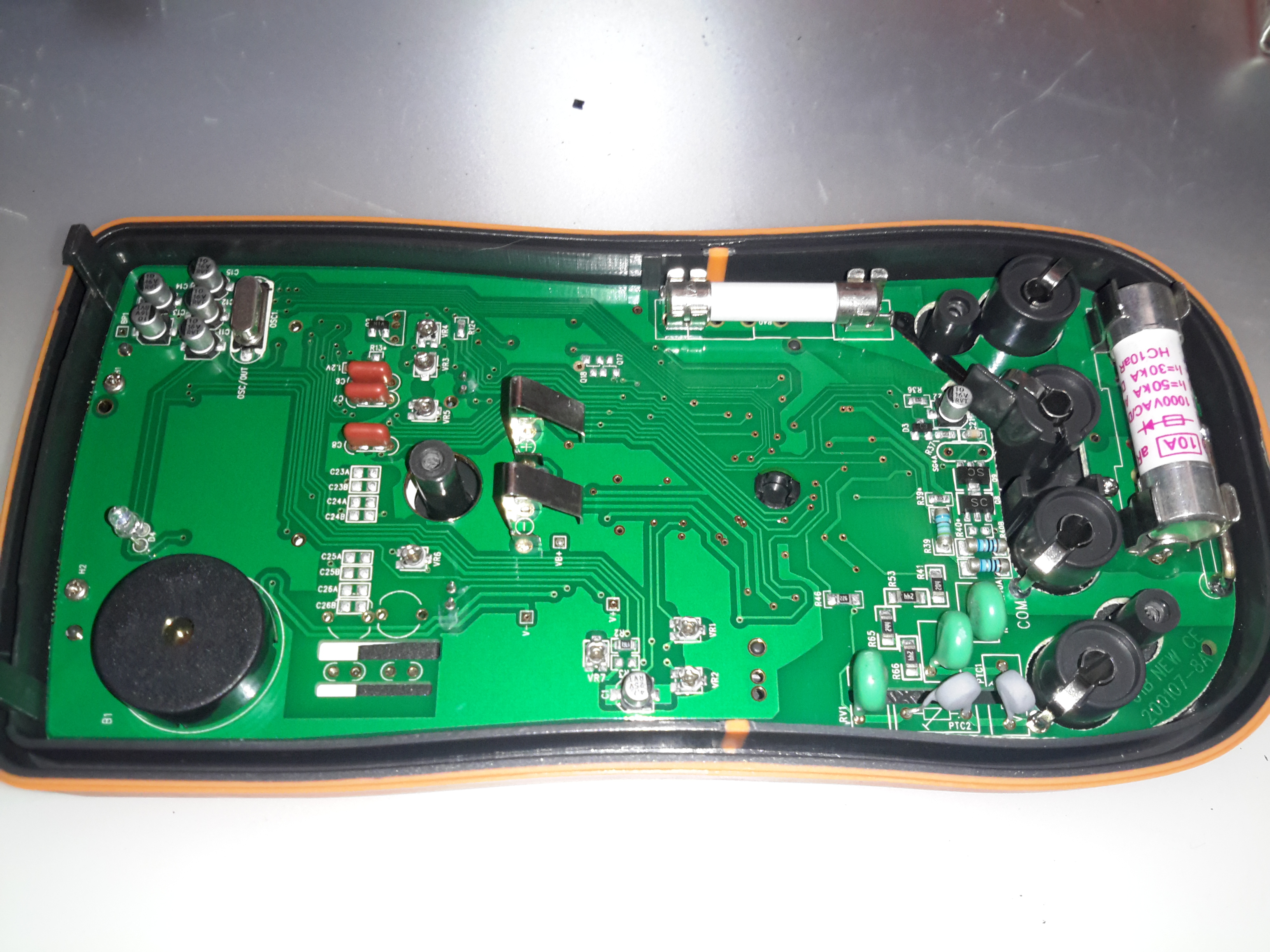
Since I can’t have anything without seeing how it’s put together, here’s the inside of the DMM. (Fuse access is only possible by taking the back cover off as well. The 9v PP3 battery has a seperate cover).
PCB Rear Bottom
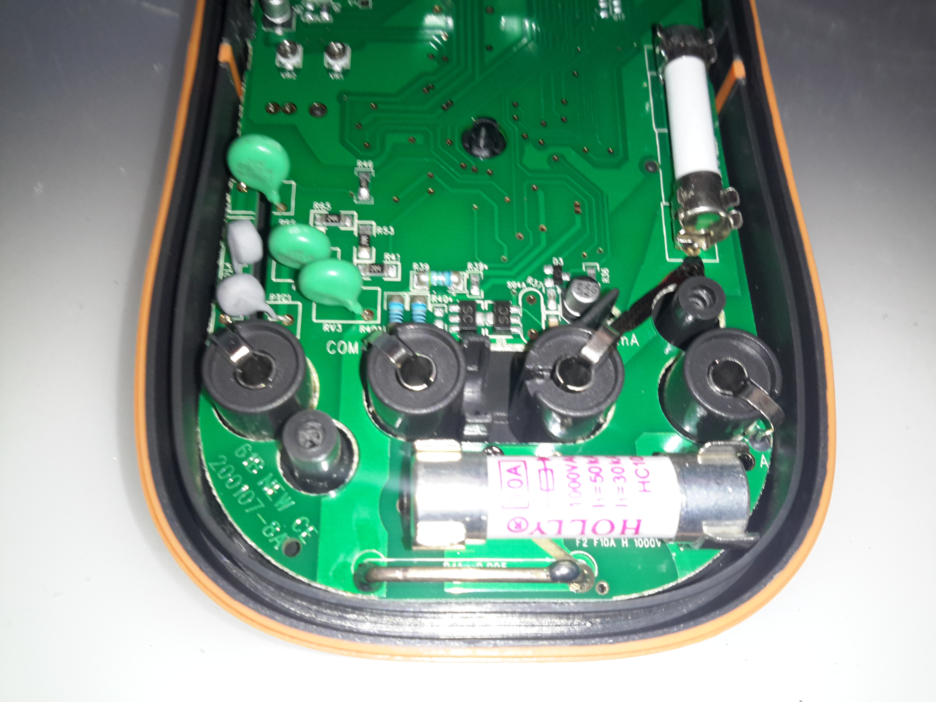
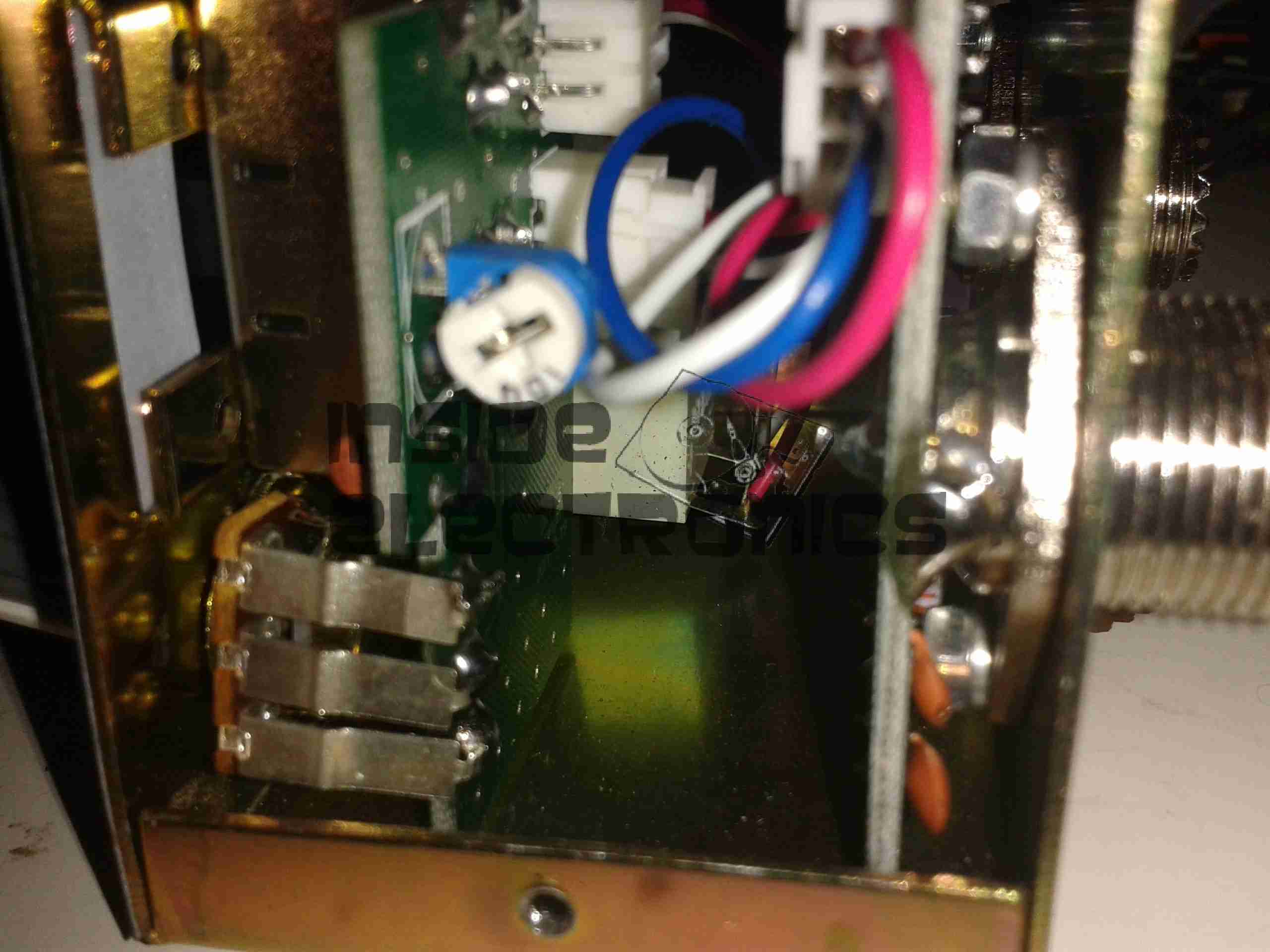
He’s the input section of the meter, with the 10A HRC fuse & current shunt for the high-amps range. The other fuse above is for the mA/µA ranges. The back cover has a wide lip around the edge, that slots into a recess in the front cover, presumably for blast protection if the meter should meet a sticky end. The HRC fuses are a definite improvement over the cheap DMMs, they only have 15mm glass fuses, and no blast protection built into the casing.
There are some MOVs for input protection on the volts/ohms jack, the jacks themselves are nothing more than stampings though.
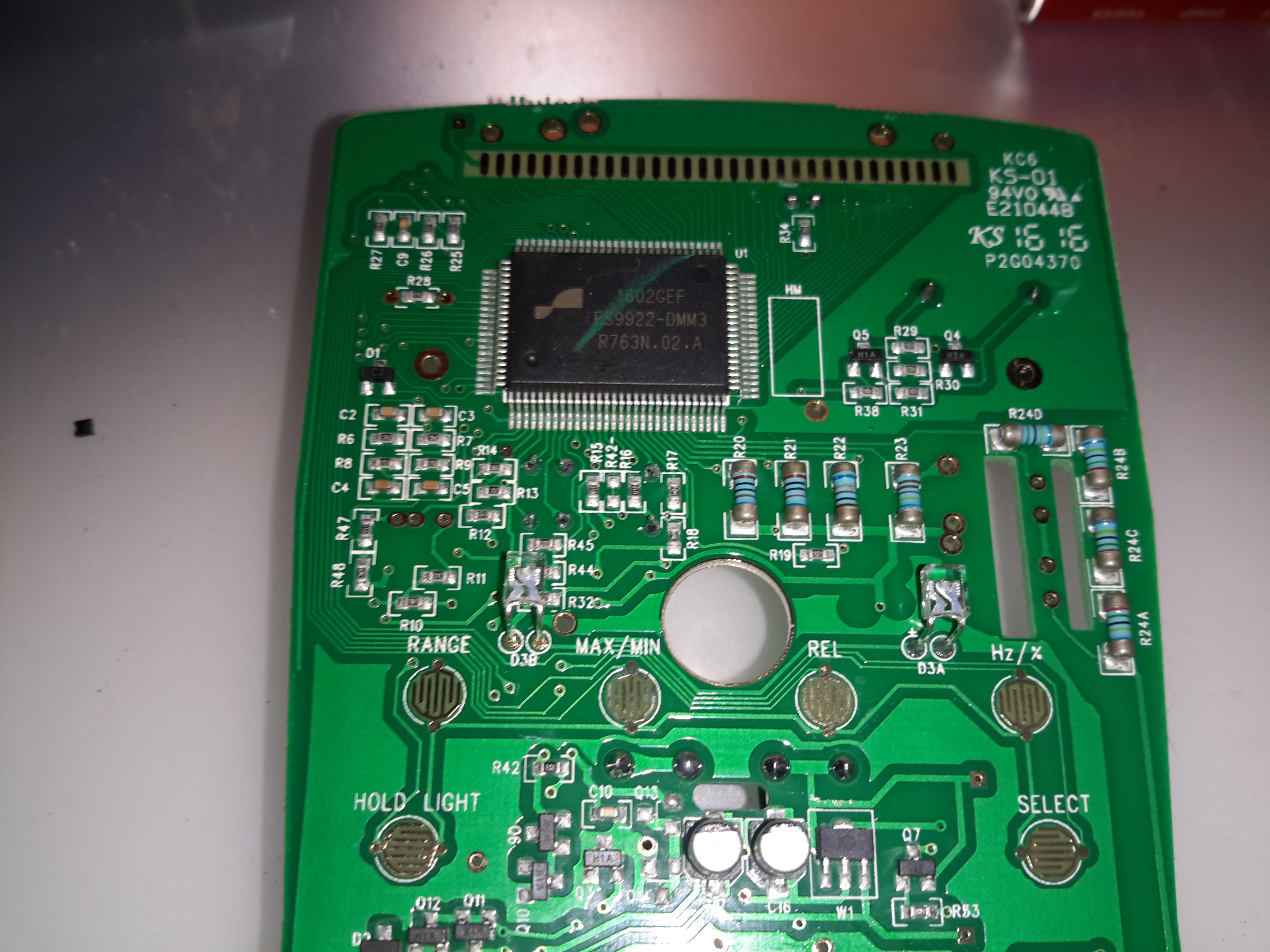
PCB Rear Top
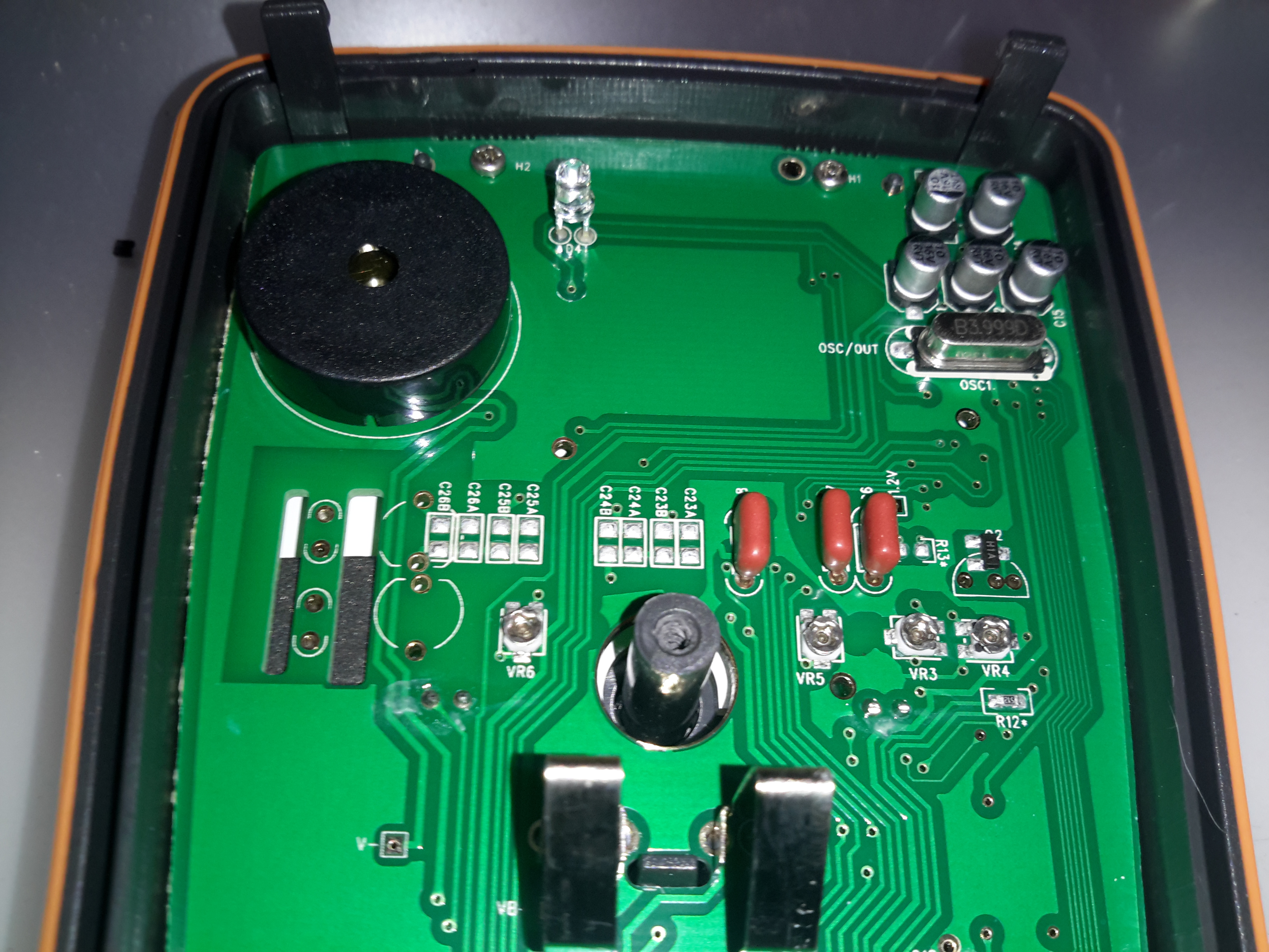
Not much at the other side of the board, there’s the IR LED for the RS232 interface & the beeper.
PCB Front
Most of the other components are on the other side of the PCB under the LCD display. The range switch is in the centre, while the main chipset is on the left.
DMM Chipset
The chipset of this meter is a FS9922-DMM3 from Fortune Semiconductor, this is a dedicated DMM chipset with built in ADCs & microcontroller.
I recently came across these on eBay, so I thought I’d grab one to see how they function, with all the metrics they display, there’s potential here for them to be very useful indeed.
One of the best parts is that no wiring is required between the sensor board & the LCD head unit – everything is transmitted over a 2.4GHz data link using NRF24L01 modules.
Above is the display unit, with it’s colour LCD display. Many features are available on this, & they appear to be designed for battery powered systems.
Monitor PCB
Another PCB handles the current & voltage sensing, so this one can be mounted as close to the high current wiring as possible.
Monitor PCB Microcontroller
The transmitter PCB is controlled with an STM8S003F3 microcontroller from ST Microelectronics. This is a Flash based STM with 8KB of ROM, 1KB of RAM & 10-bit ADC. The NRF24L01 transceiver module is just to the left.
There’s only a single button on this board, for pairing both ends of the link.
Output MOSFET
The high current end of the board has the 0.0025Ω current shunt & the output switch MOSFET, a STP75NF75 75v 75A FET, also from ST Microelectronics. A separate power source can be provided for the logic via the blue terminal block instead of powering from the source being measured.
LCD Unit Rear
Here’s the display unit, only a pair of power terminals are provided, 5-24v wide-range input is catered for.
LCD Unit PCB
Unclipping the back of the board reveals the PCB, with another 2.4GHz NRF24L01 module, and a STM8S005K6 microcontroller in this case. The switching power supply that handles the wide input voltage is along the top edge of the board.
Unfortunately I didn’t get any instruction manual with this, so some guesswork & translation of the finest Chinglish was required to get my head round the way everything works. To make life a little easier for others that might have this issue, here’s a list of functions & how to make them work.
LCD Closeup
On the right edge of the board is the function list, a quick press of the OK button turns a function ON/OFF, while holding it allows the threshold to be set.
When the output is disabled by one of the protection functions, turning that function OFF will immediately enable the output again.
The UP/DOWN buttons obviously function to select the desired function with the cursor just to the left of the labels. Less obviously though, pressing the UP button while the very top function is selected will change the Amp-Hours display to a battery capacity icon, while pressing DOWN while the very bottom function is selected will change the Watts display to Hours.
The round circle to the right displays the status of a function. Green for OK/ON Grey for FAULT/OFF.
OVP: Over voltage protection. This will turn off the load when the measured voltage exceeds the set threshold.
OPP: Over power protection. This function prevents a load from pulling more than a specified number of watts from the supply.
OCP: Over current protection. This one’s a little more obvious, it’ll disable the output when the current measured exceeds the specified limit.
OUT: This one is the status of the output MOSFET. Can also be used to manually enable/disable the output.
OFT: Over time protection. This one could be useful when charging batteries, if the output is enabled for longer than the specified time, the output will toggle off.
OAH: Over Amp-Hours protection. If the counted Amp-Hours exceeds the set limit, the output will be disabled.
Nom: This one indicates the status of the RF data link between the modules, and can be used to set the channel they operate on.
Pairing is achieved by holding the OK button, selecting the channel on the LCD unit, and then pressing the button on the transmitter board. After a few seconds, (it appears to scan through all addresses until it gets a response) the display will resume updating.
This function would be required if there are more than a single meter within RF range of each other.
I’ve not yet had a proper play with all the protection functions, but a quick mess with the OVP setting proved it was very over-sensitive. Setting the protection voltage to 15v triggered the protection with the measured voltage between 12.5v-13.8v. More experimentation is required here I think, but as I plan to just use these for power monitoring, I’ll most likely leave all the advanced functions disabled.
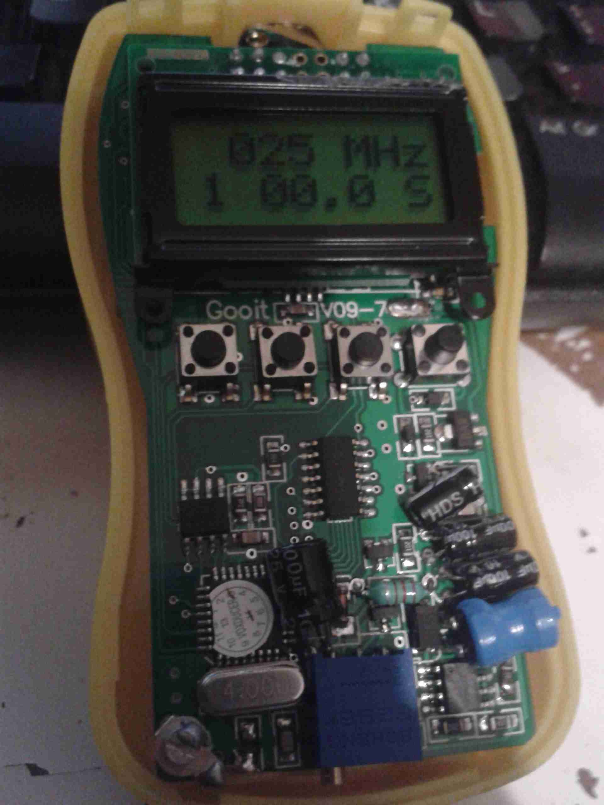
Unfortunately the manual for the eBay GY561 Frequency & RF Power Meter is very badly translated, but I think I have figured out the calibration procedure, so here it goes 🙂
Initial Screen
On removing the front cover, which is just clipped on, there are 4 buttons. The only button that is usually available is the one on the far right, the power button.
I will term these buttons A, B, C, D, starting from the left side.
To get into the initial calibration screen, in the above image, hold button A while the power button (D) is pressed. Release the power button (D), then release button A.
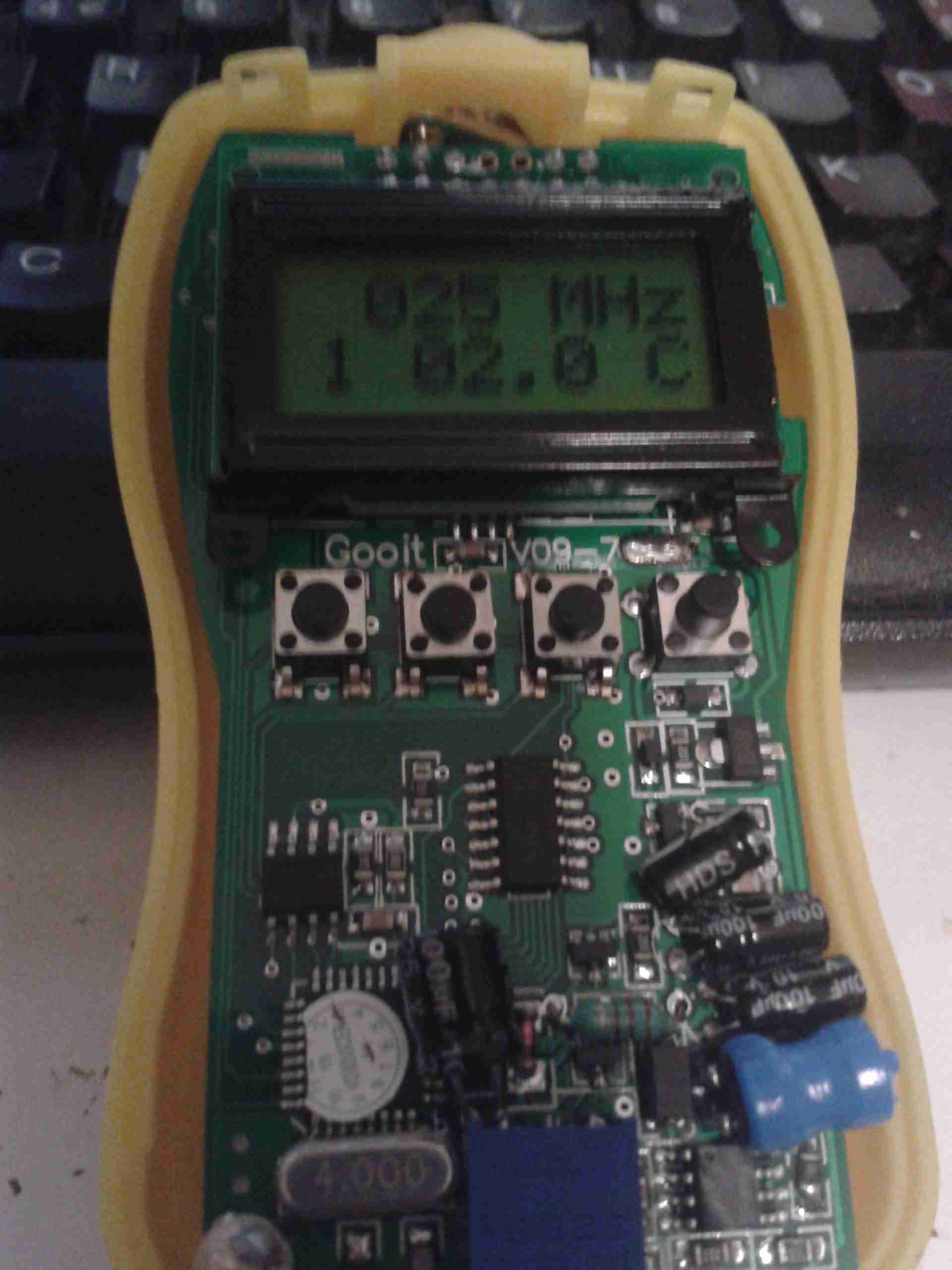
The meter will show the screen above, where the frequency to calibrate can be chosen. This goes in 5MHz steps, 0-500MHz, using the B button to go down in frequency, and the C button to go up.
Once you’ve selected the frequency you wish to calibrate against, press button A, and the following screen will appear:
Frequency Calibration Screen
On this screen, the actual calibration can be done.
The number in the bottom left signifies the power level setting, from 1-5. The centre number is the calibration setting in Watts. The D in the bottom corner signifies that the setting is at the factory default.
Button C will cycle through the power level settings, for 2W, 5W, 10W 20W, 40W. This allows calibration at different power levels per frequency.
Once you have the frequency to calibrate, and you’ve selected the power level to calibrate at, connect a known RF power source to the input of the unit.
At this point, key the transmitter, and press button A. The display will change to the following:
Calibration Stage 2
When on this screen, you can set the power level of your RF source. Use the A key for +0.1W, the B key for +1W, and the C key for +10W.
Once you’ve keyed in the power of your source, press button D to save the setting. The “S” in the bottom corner will change to a “C”, to indicate a user calibration has been entered:
Calibration Complete
If you make a mistake with entering the power level, press the “C” key to cycle up to 60W, once at this level, another press of the button will reset the reading to zero. You can then enter the power level again.
If you wish to revert a user-entered setting to the factory default, press button B on the page above. The “D” will reappear in the bottom corner to indicate the setting has been restored.
At this point you can either press button C to calibrate at another power level for this frequency, or press button D to go back to the frequency selection.
Press button D again when at the frequency selection page to turn the unit off. The unit will then power up normally next time the power button (D) is pressed.
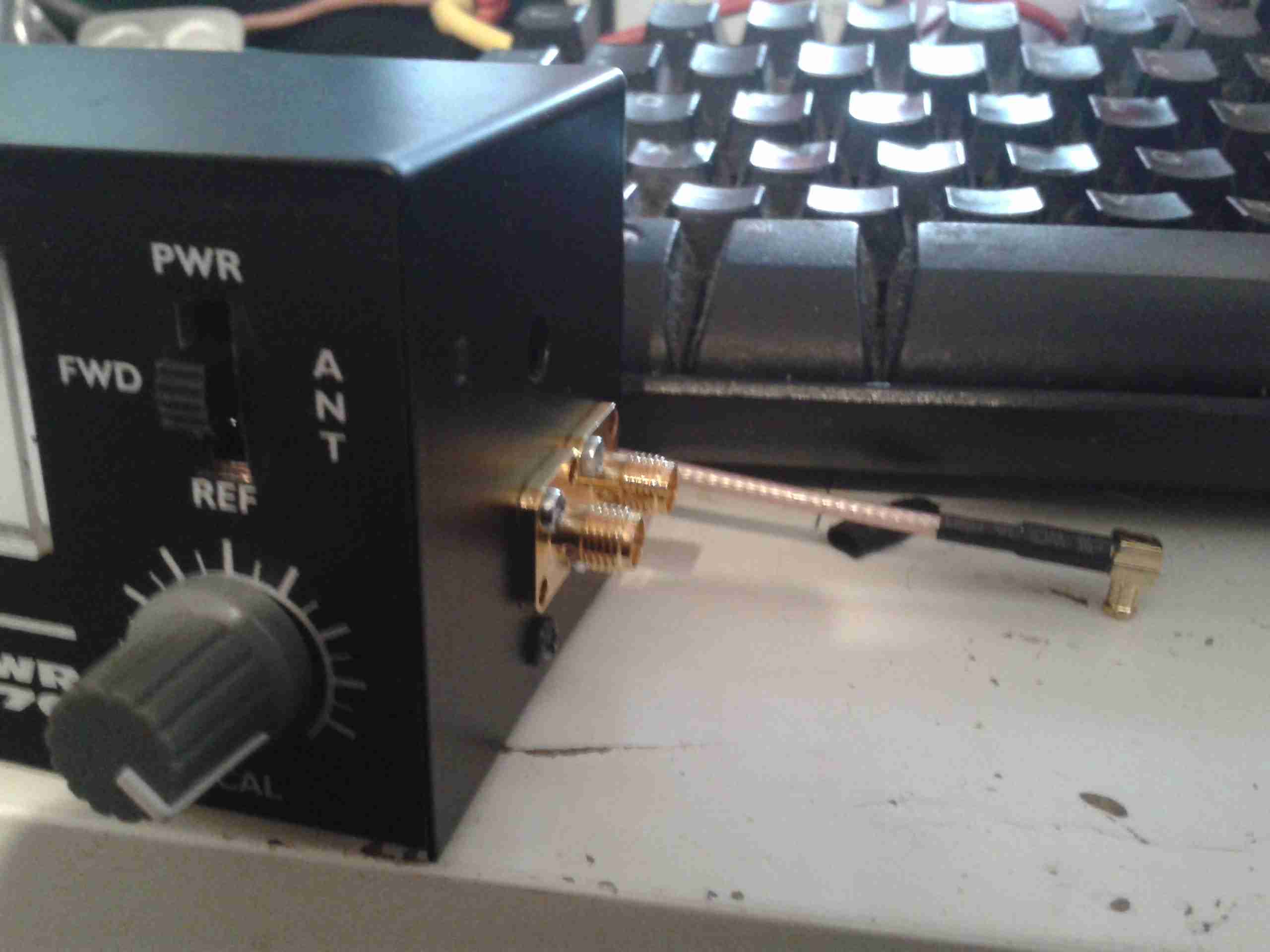
Now the final bits have arrived for the SWR Meter module, I can do the final assembly.
SMA Connectors
Here the SMA connectors are installed on the side of the eBay meter, for forward & reverse power tap.
These are simply tee’d off the wiring inside the meter where it connects to the switch.
Uncalibrated
The meter is connected to the module via a pair of RG58 SMA leads, above is a readout before calibration, using one of my Baofeng UV-5Rs.
I’m using my GY561 eBay Power Meter as a calibration source, and as this isn’t perfect, the readings will be slightly off. If I can get my hands on an accurate power meter & dummy load I can always recalibrate.
Tools are only as accurate as the standard they were calibrated from!
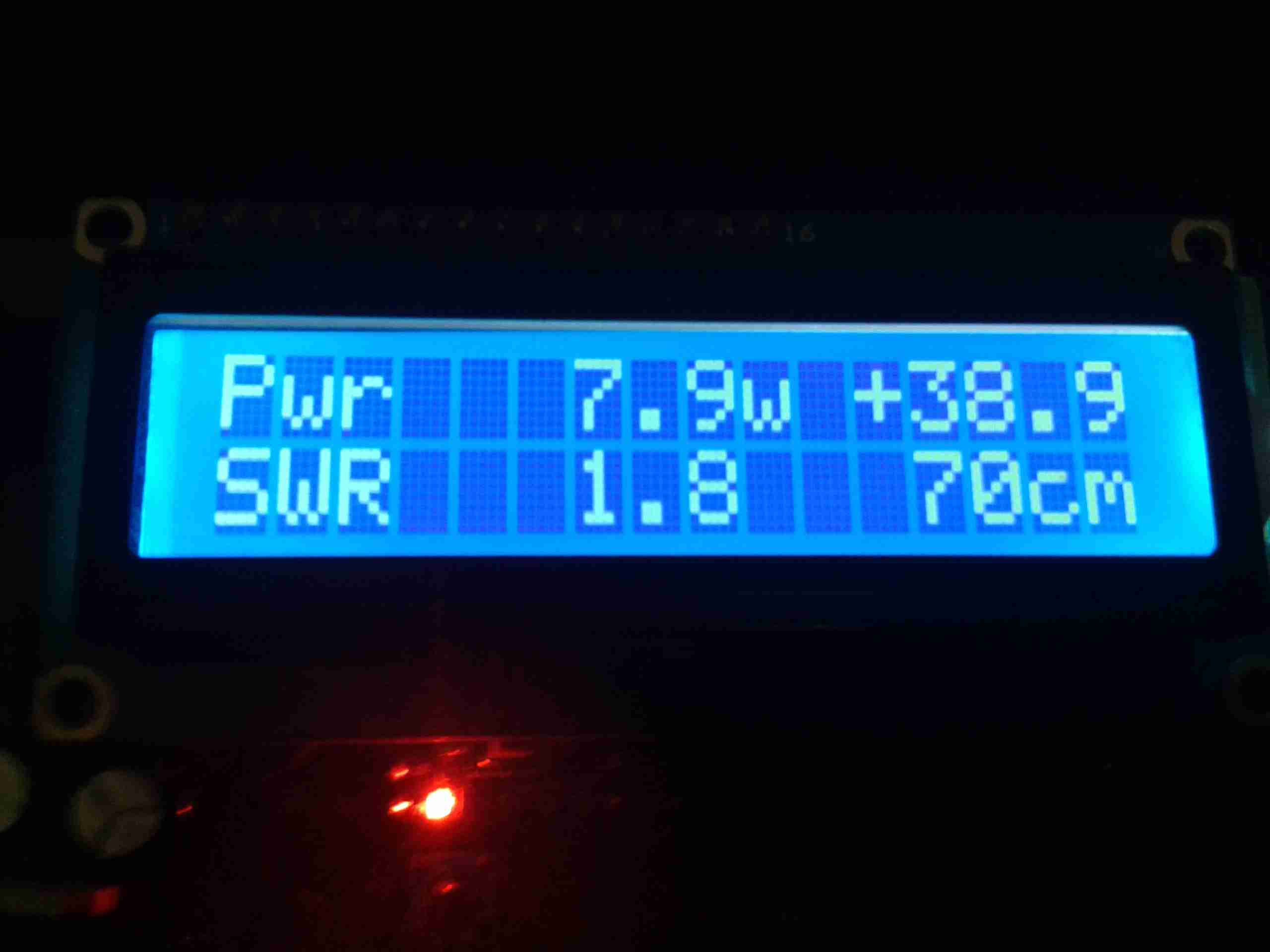
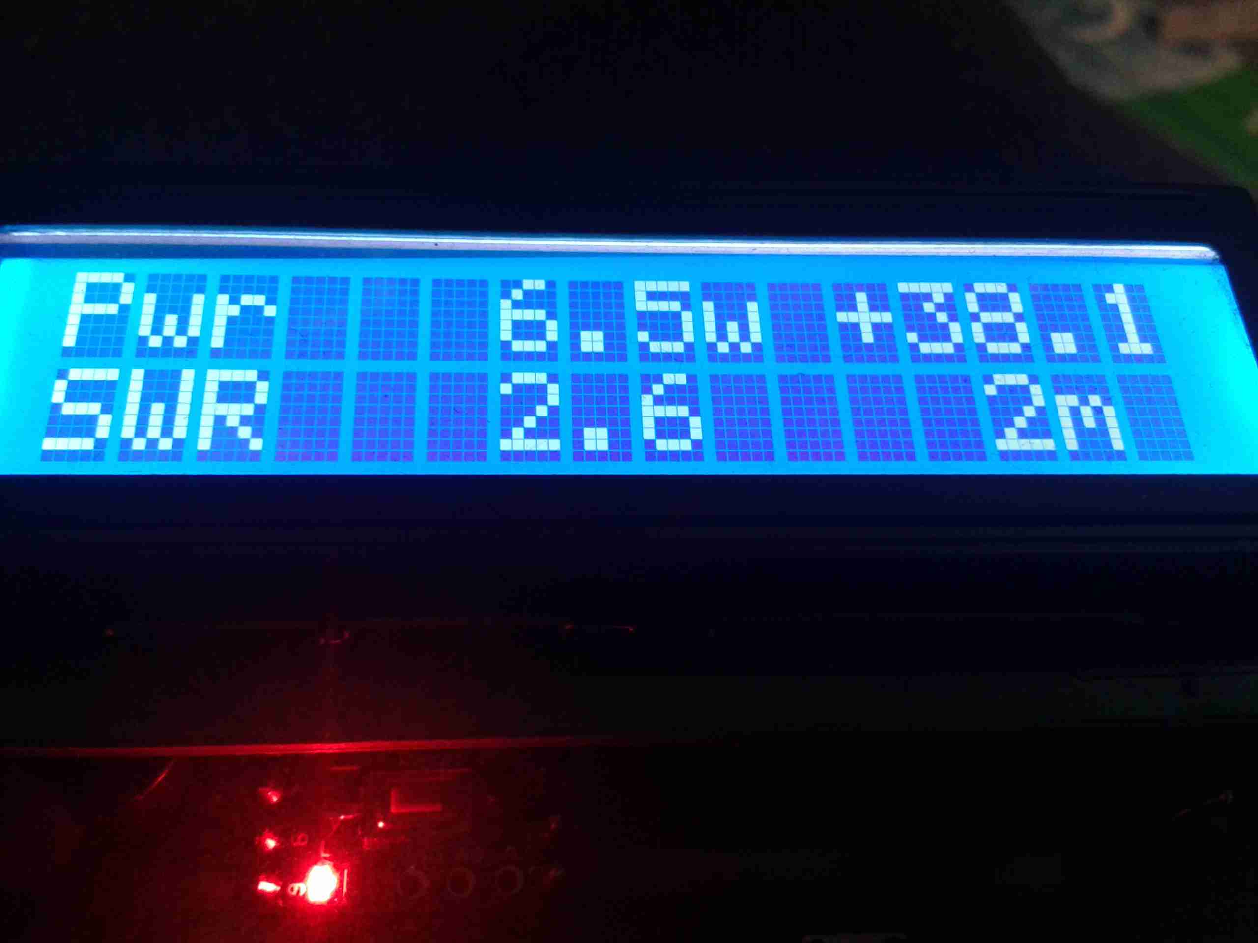
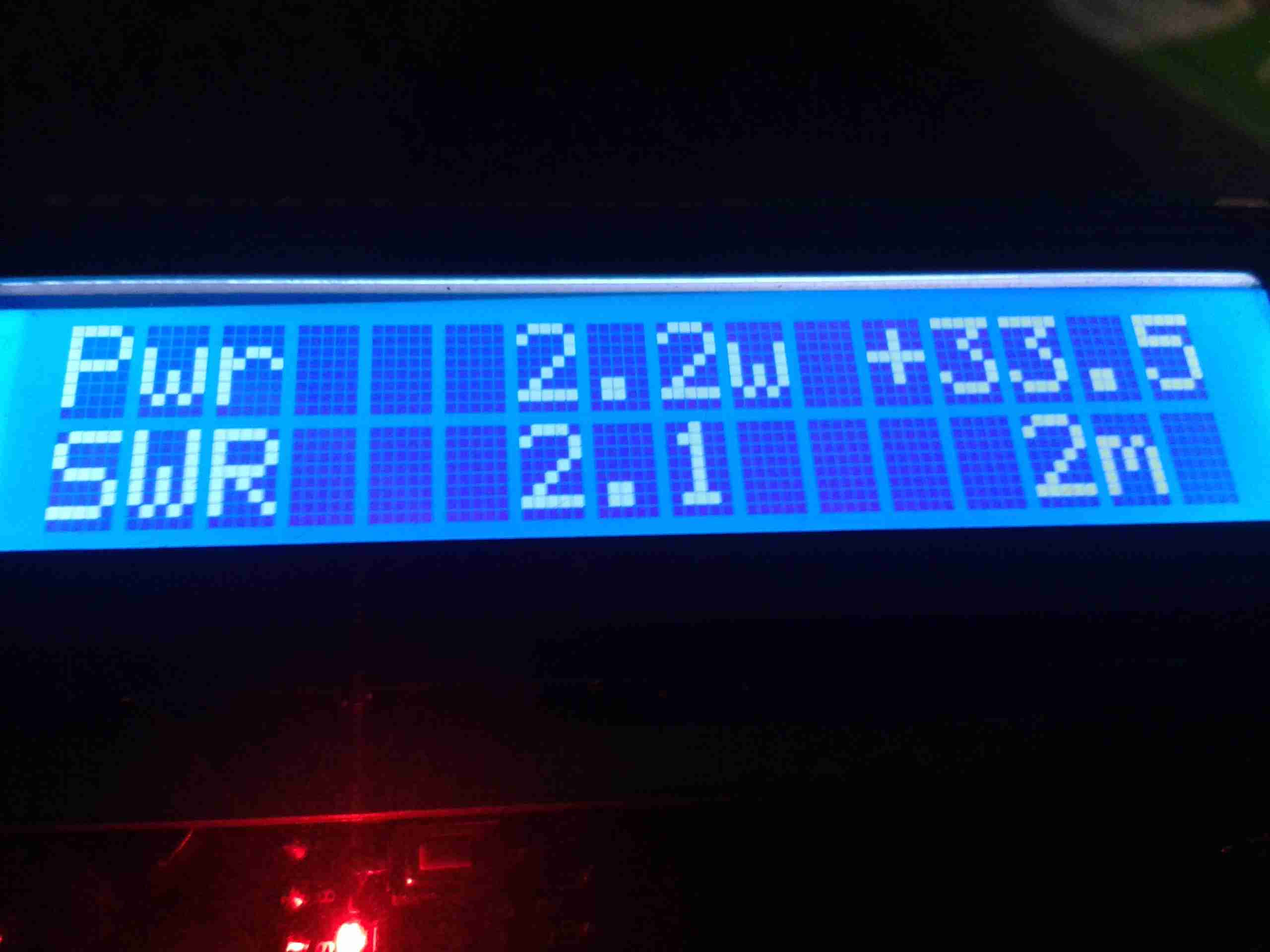
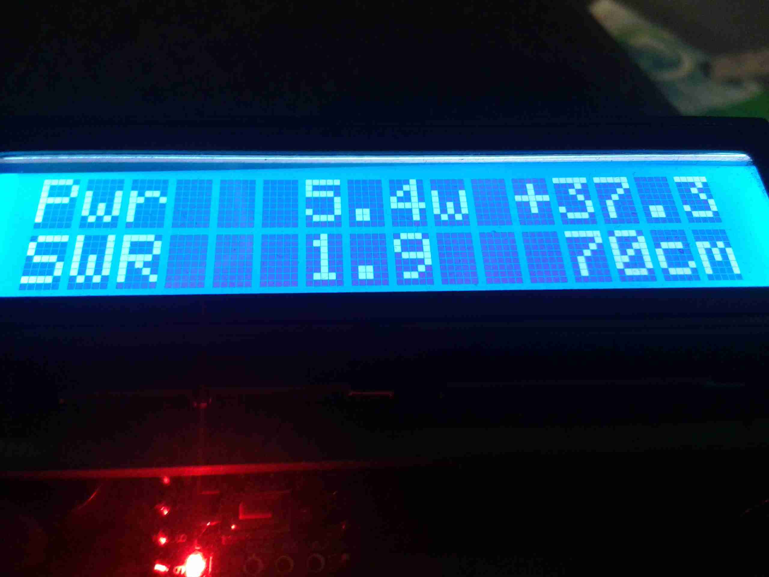
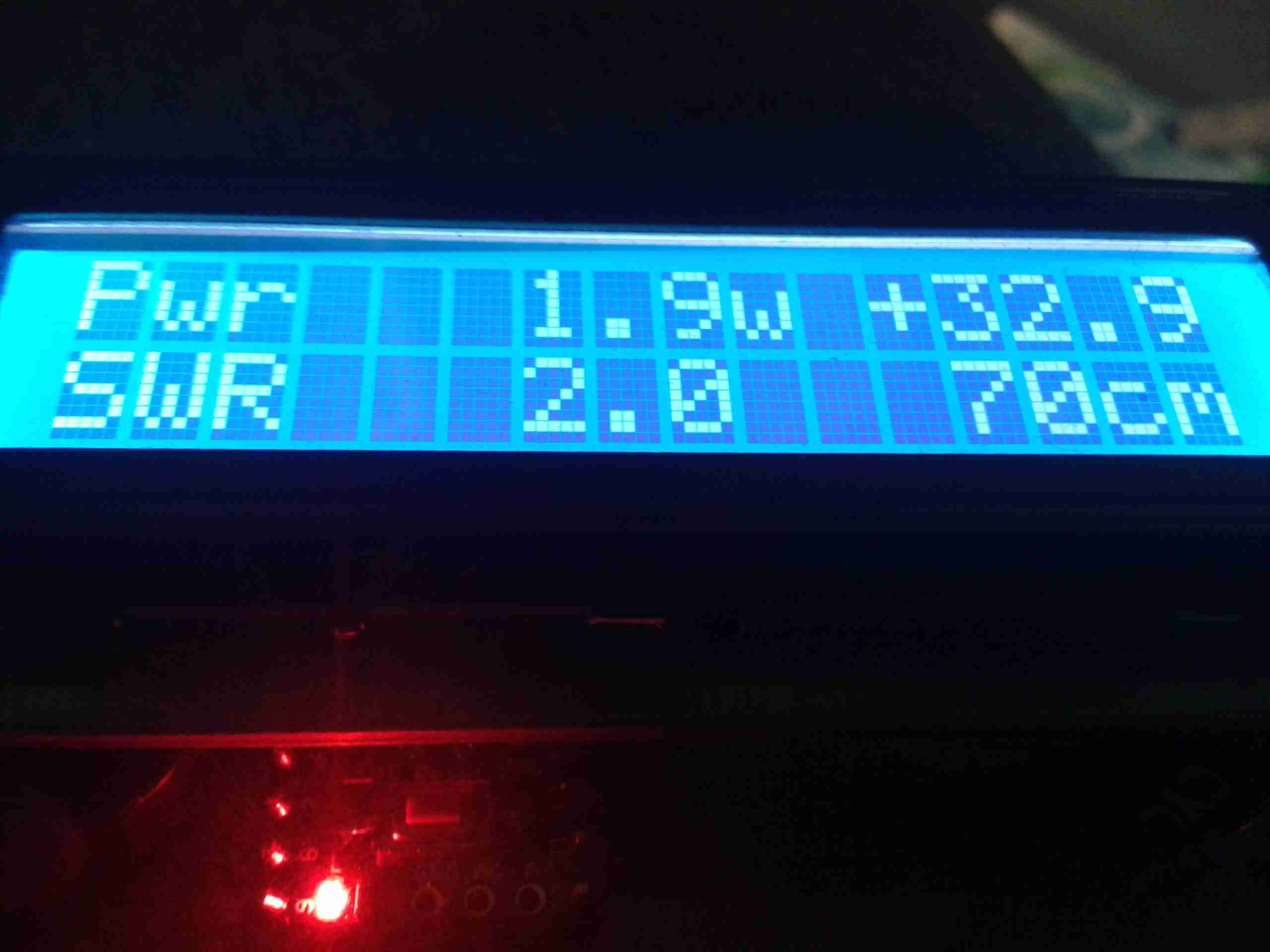
After calibration, here’s the readings on 2m & 70cm. These readings coincide nicely with the readings the GY561 produce, to within a couple tenths of a watt. SWR is more than 1:1 as the dummy load in the GY561 isn’t exactly 50Ω.
High Power VHFLow Power VHFHigh Power UHFLow Power UHF
Shortly I’ll calibrate against 6m & 10m so I can use it on every band I have access to 🙂
The latest addition to my radio shack is the GY561 frequency & power meter, which has already come in useful for measuring the output power of all my radios.
GY561
It’s a small device, roughly the same size & weight as a stock UV-5R. Power is provided by 3 AAA cells.
Display
The display is a standard HD44780 8×2 module. The display on this unit isn’t backlit, so no operating in the dark.
Cover Removed
The cover pops off easily to allow access to the internals, without having to remove any screws!
The 4 screws on the back of the unit hold the heatsink plate for the 50W 50Ω dummy load resistor.
Removing the cover reveals a couple of adjustments, for frequency & RF power calibration.
There are also 3 tactile switches that aren’t on the front panel. According to the manual (which in itself is a masterpiece of Chinglish), they are used to software calibrate the unit if an accurate RF power source is available. I will attempt to do a reasonable translation when time allows.
Disassembly further than this involves some desoldering in awkward places, so a search of the internet revealed an image of the rest of the internal components. In the case of my meter, all the part numbers have been scrubbed off the ICs in an attempt to hide their purpose. While it’s possible to cross-reference IC databooks & find the part numbers manually, this process is a time consuming one. Luckily the image I managed to locate doesn’t have the numbers scrubbed.
Total Disassembly
Under the LCD is some 74HC series logic, and a prescaler IC as seen in the previous frequency counter post. However in this unit the prescaler is a MB506 microwave band version to handle the higher frequencies specified.
In this case however the main microcontroller is an ATMEGA8L.
This is complemented by a SN54HC393 4-bit binary counter for the frequency side of things. This seems to make it much more usable down to lower frequencies, although the manual is very generous in this regard, stating that it’s capable of reading down to 1kHz. In practice I’ve found the lowest it reliably reads the frequency input is 10MHz, using my AD9850 DDS VFO Module as a signal source.
It did however read slightly high on all readings with the DDS, but this could have been due to the low power output of the frequency source.
Just like the other frequency counter module, this also uses a trimmer capacitor to adjust the microcontroller’s clock frequency to adjust the calibration.
The power supply circuitry is in the bottom left corner of the board, in this case a small switching supply. The switching regulator is needed to boost the +4.5v of the batteries to +5v for the logic.
Also, as the batteries discharge & their terminal voltage drops, the switching regulator will allow the circuit to carry on functioning. At present I am unsure of the lower battery voltage limit on the meter, but AAA cells are usually considered dead at 0.8v terminal voltage. (2.4v total for the 3 cells).
When turned on this meter draws 52mA from the battery, and assuming 1200mAh capacity for a decent brand-name AAA cell, this should give a battery life of 23 hours continuous use.
On the back of the main PCB is a 5v relay, which seems to be switching an input attenuator for higher power levels, although I only managed to trigger it on the 2m band.
Finally, right at the back attached to an aluminium plate, is the 50Ω dummy load resistor. This component will make up most of the cost of building these, at roughly £15.
On my DVM, this termination reads at about 46Ω, because of the other components on the board are skewing the reading. There are a pair of SMT resistors, at 200Ω & 390Ω in series, and these are connected across the 50Ω RF resistor, giving a total resistance of 46.094Ω.
This isn’t ideal, and the impedance mismatch will probably affect the calibration of the unit somewhat.
The heatsinking provided by the aluminium plate is minimal, and the unit gets noticeably warm within a couple of minutes measuring higher power levels.
High power readings should definitely be limited to very short periods, to prevent overheating.
The RF is sampled from the dummy load with a short piece of Teflon coax.
There’s a rubber duck antenna included, but this is pretty useless unless it’s almost in contact with the transmitting antenna, as there’s no input amplification. It might be handy for detecting RF emissions from power supplies, etc.
For the total cost involved I’m not expecting miracles as far as accuracy is concerned, (the manual states +/-10% on power readings).
The frequency readout does seem to be pretty much spot on though, and the ability to calibrate against a known source is handy if I need some more accuracy in the future.
I’ve also done an SWR test on the dummy load, and the results aren’t good.
At 145.500 MHz, the SWR is 3:1, while at 433.500 it’s closer to 4:1. This is probably due to the lower than 50Ω I measured at the meter’s connector.
These SWR readings also wander around somewhat as the load resistor warms up under power.
I’ll probably also replace the AAA cells with a LiPo cell & associated charge/protection circuitry, to make the unit chargeable via USB. Avoiding disposable batteries is the goal.
Following on from the earlier power tests on my Baofeng HTs, here’s the readings from the Wouxun KG-UV950P. Power is a little lower than specified, but this is probably due to the supply voltage being a bit less than 13.8v. These readings were taken at a supply voltage of 12.88v.
The same frequencies were used, 145.500 & 433.500 for the VHF/UHF tests. For the 6/10m tests 27MHz & 50MHz were used.
The power meter was connected with 1 metre of RG58 dual-screened cable with N-type connectors.
I’ve noticed that the RF power output from the Chinese radios can be quite variable from model to model, and even from individual radios of the same model & batch.
I’ve bought an RF Power meter (GY561) to do some tests on the HTs I have at present.
All tests were performed with the radio fully charged & still on the charging base, to make sure the supply voltage remained constant at 8.4v throughout the tests.
Frequencies used were 145.500 & 433.500 for VHF & UHF respectively.
The power meter was connected with ~8″ of RG174 Coax.
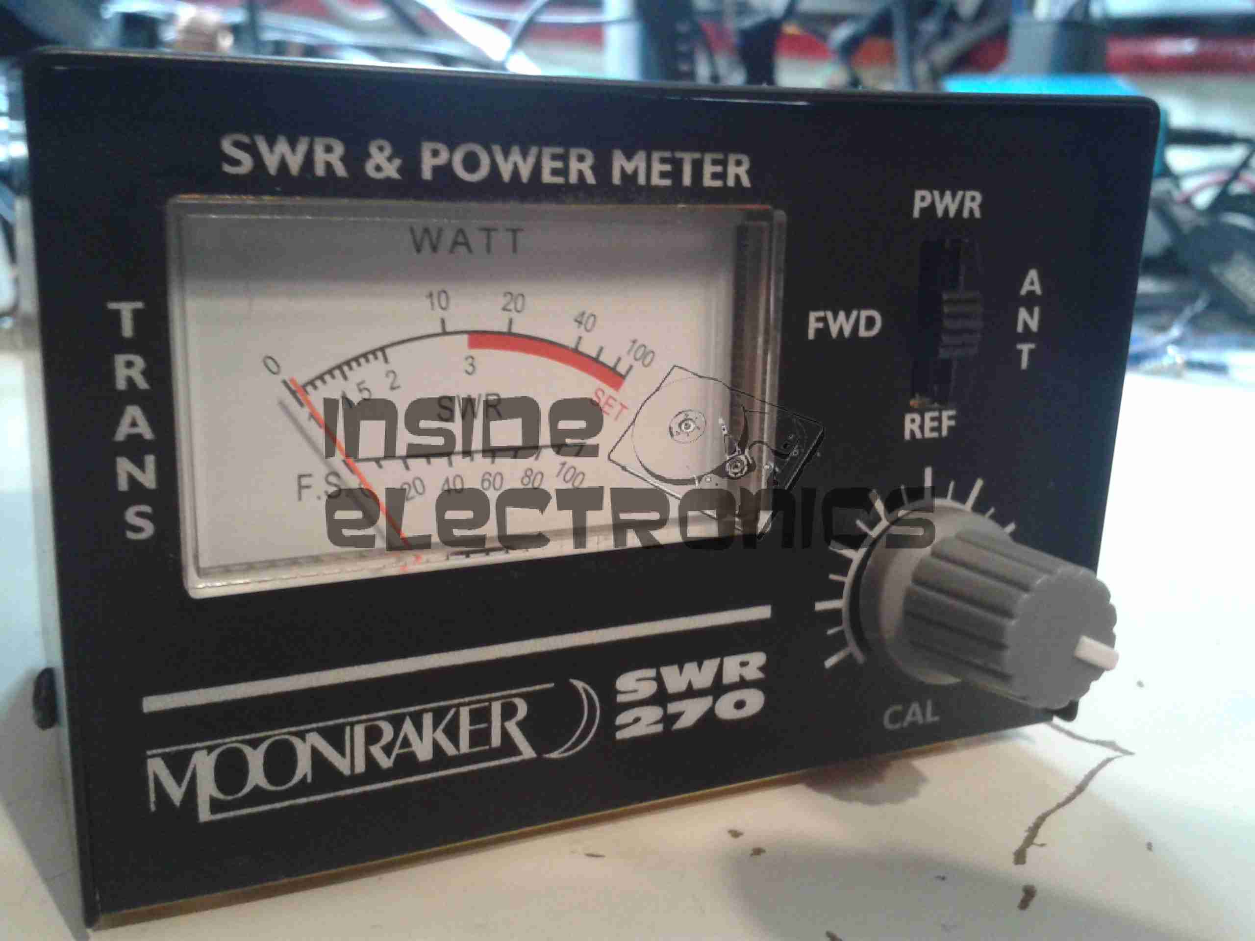
As I’m building up my radio shack, I figured an SWR meter would be a handy addition to my arsenal. This is a cheap Moonraker brand meter, which also will measure RF power. Above the front of the meter is shown, with the moving coil meter movement on the left, calibration adjustment on the right & the forward/reverse power switch.
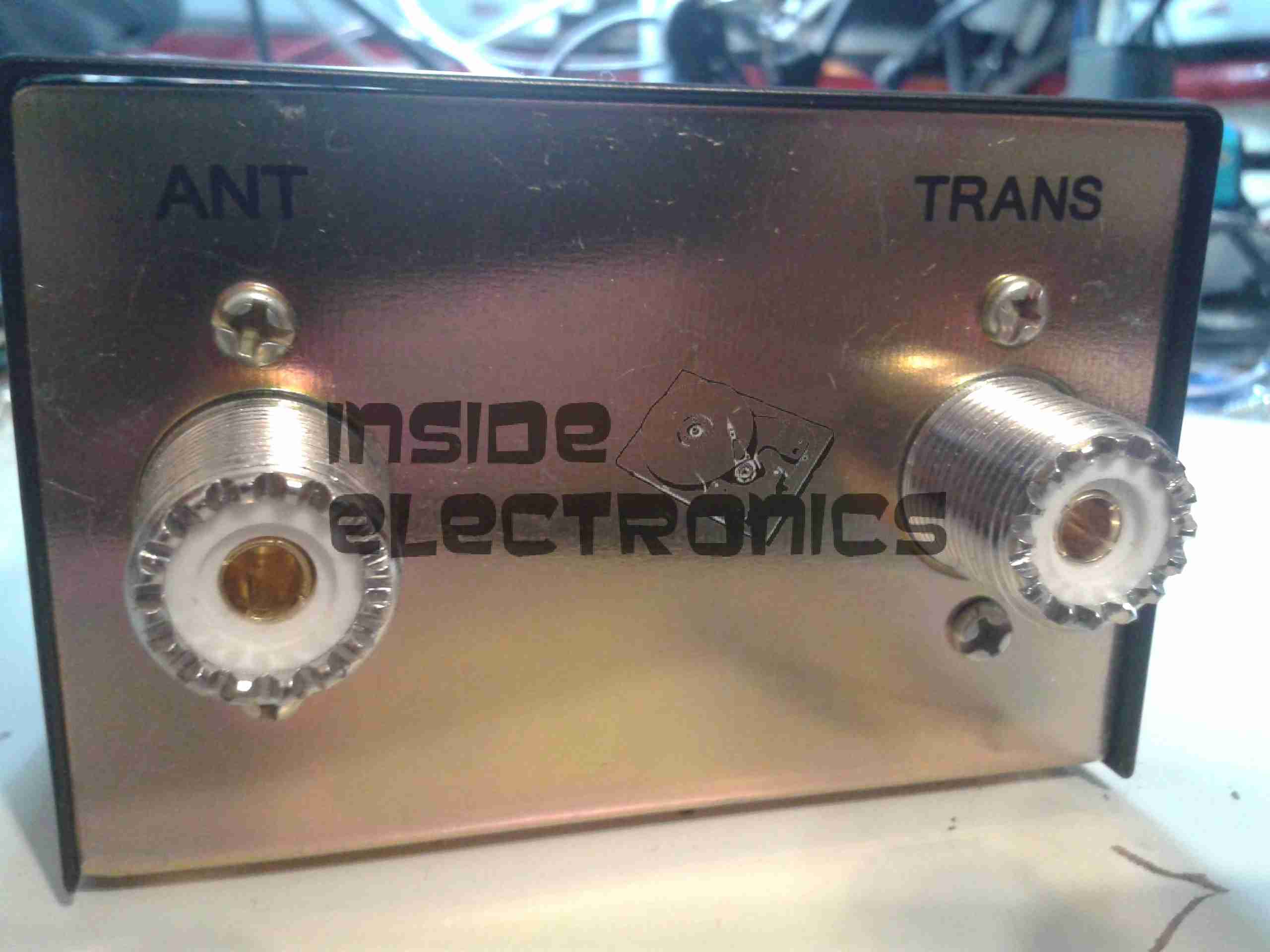
Meter Rear
For connections, standard SO-259 jacks are provided. The casing is sturdy 1mm steel. This is good, considering it’ll probably take a beating in my portable radio bag.
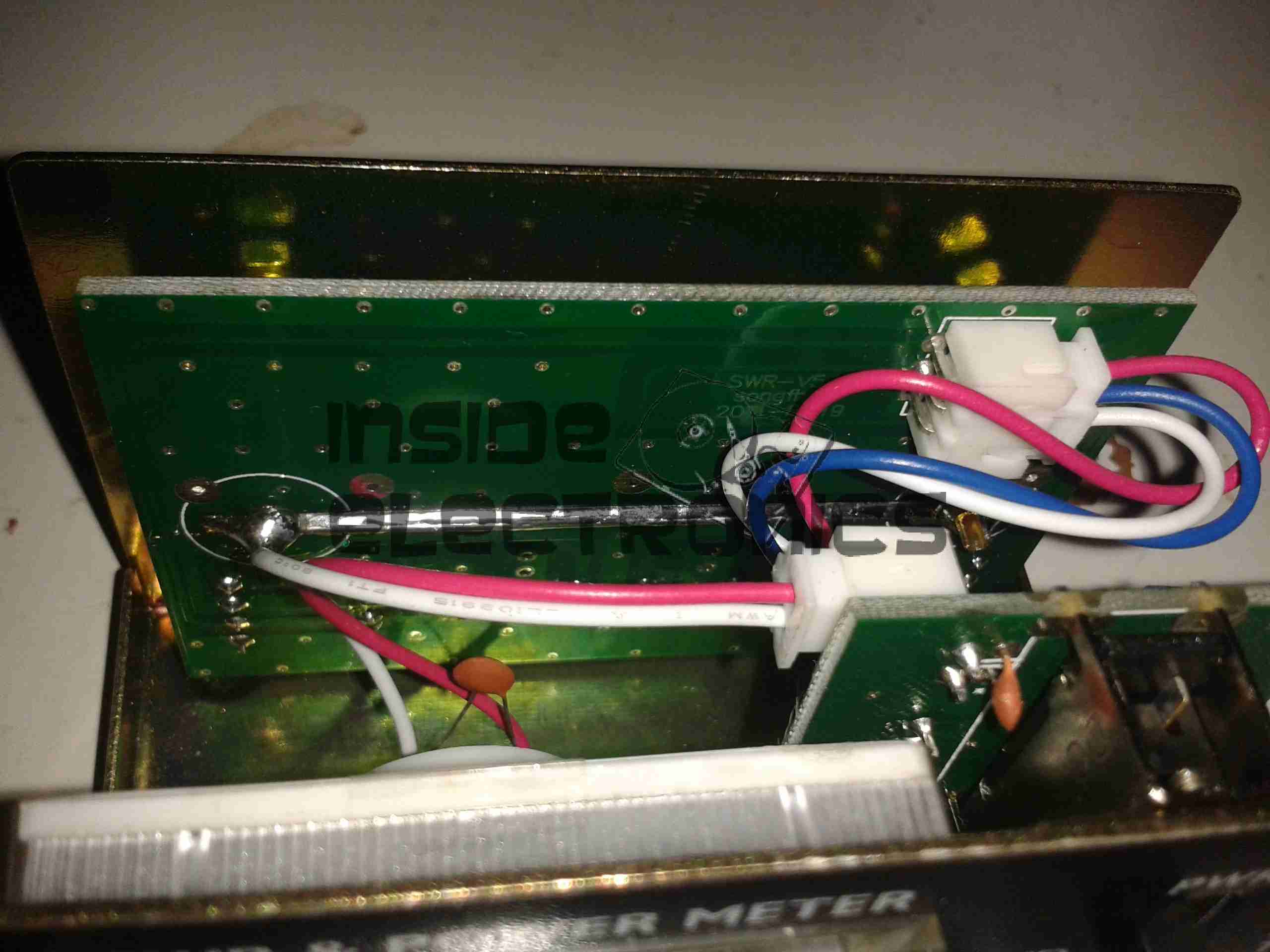
Directional Coupler PCB
Here the cover is removed, showing some of the internals. The large PCB across the back is the directional coupler.
Directional Coupler Circuit
The SO-259 connectors are bridged with a transmission line, (the track covered in solder in the image below), while there are a pair of sense lines running alongside. This main line is electromagnetically coupled to the two smaller sense lines, which are terminated at one end with resistors, with diodes at the other to rectify the coupled signal.
The termination resistors are sized to match the impedance of the sense lines.
The diodes, having rectified the coupled RF, produce DC voltages representing the value of the forward & reverse RF power. These DC voltages are smoothed with the capacitors.
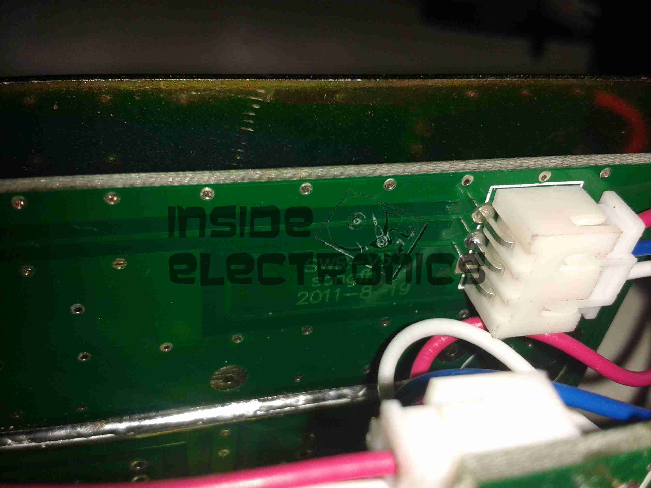
PCB Marking
The PCB is dated 19-8-2011, so it’s a fairly old design.
Adjustments
Here is visible the back of the user calibration adjuster, with the factory calibration trimmer.
Meter Movement
Back of the meter movement. This is a standard moving coil type. Nothing special.
This meter will soon be modified to accept connection of an external Arduino-based SWR & power meter, which I can calibrate individually for each band.
Stay tuned for that upcoming project.
This is the Current Cost CC128 Real Time Power Meter. Shown here is the display unit, British Gas issued these free to some customers.
This unit measures current power draw in Watts, cost of power currently being used (requires unit price to be set), overall kWh usage over the past 1, 7 or 30 days & power trends during the day, night & evening. Also displays current time & current room temperature.
Display PCB
Here the front panel of the display has been un-clipped. At the bottom are the RJ-45 serial port & power connections.
This unit uses a PIC micro-controller as it’s CPU (PIC18F85J90) Just above & left of the CPU is the 433MHz SPD radio receiver module. The chips on the right of the CPU are a 25LC128 SPI serial EEPROM for data storage & a 74HC4060 14 stage binary counter, to which is connected the 32kHz clock crystal. The red wire around the top of the display is the antenna for the radio receiver.
For more info on the CC128 in general, the serial port & software for computer data logging, see this link
See this link for Current Cost’s list of software
Processor & Radio
Closeup of the ICs on the mainboard.
Transmitter Unit
Here we have the transmitter unit, with Current Transformer (CT). The red clamp fits around one of the electric meter tails & read the current going to the various circuits. This unit is powered by 2x D cells, rated at a life of 7 years.
Transmitter PCB
The PCB inside the transmitter. Again very minimal design, unknown controller IC, 433MHz radio transmitter on right hand side with wire antenna. Two barrel connectors on left hand side of board allow connection of up to two more CT clamps for measurement of 3-phase power. Centre of board is unmarked header. (ICSP?)
Current Transformer
CT unit. Inside is a coil of wire & an iron core which surrounds the cable to be measured.
PIC18F85J90
Tip Jar
If you’ve found my content useful, please consider leaving a donation by clicking the Tip Jar below!
All collected funds go towards new content & the costs of keeping the server online.