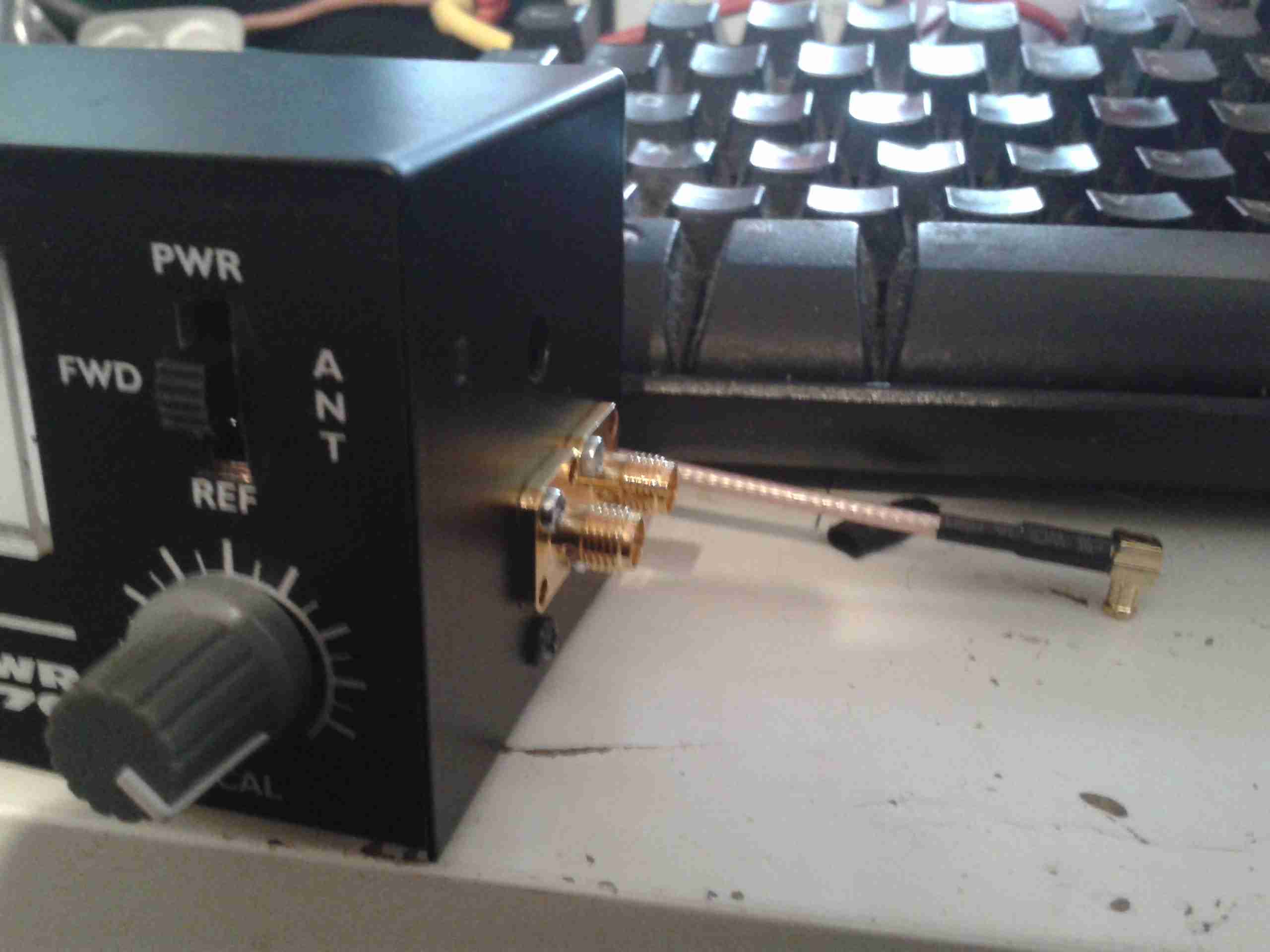
Now the final bits have arrived for the SWR Meter module, I can do the final assembly.
SMA Connectors
Here the SMA connectors are installed on the side of the eBay meter, for forward & reverse power tap.
These are simply tee’d off the wiring inside the meter where it connects to the switch.
Uncalibrated
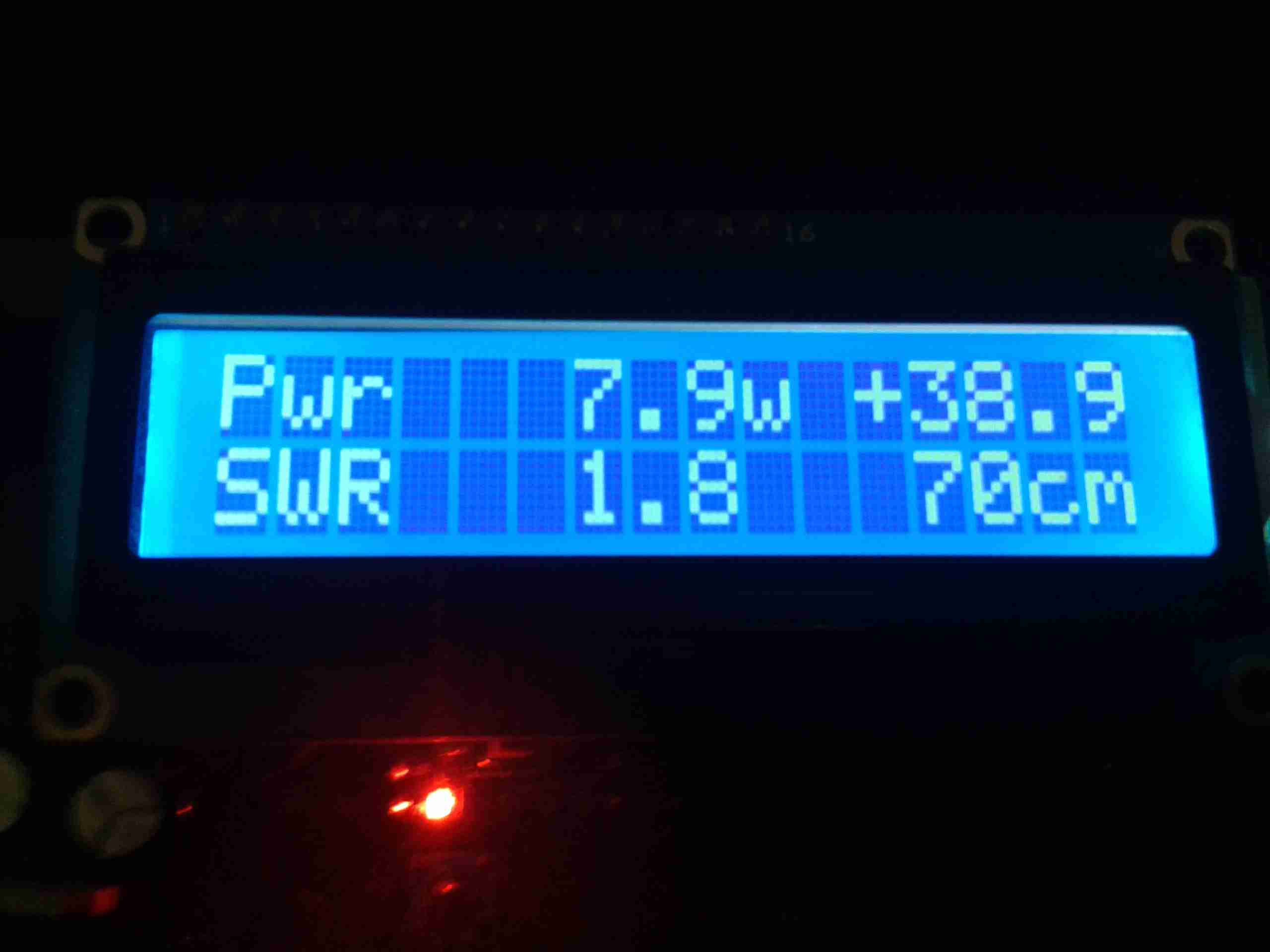
The meter is connected to the module via a pair of RG58 SMA leads, above is a readout before calibration, using one of my Baofeng UV-5Rs.
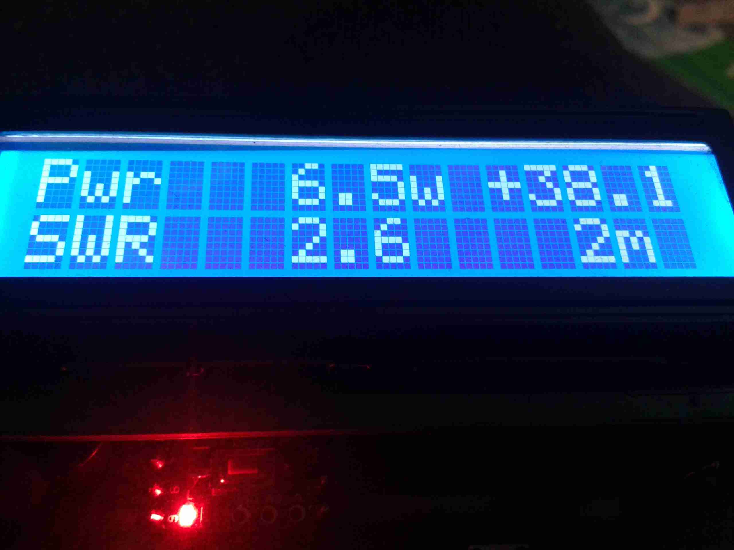
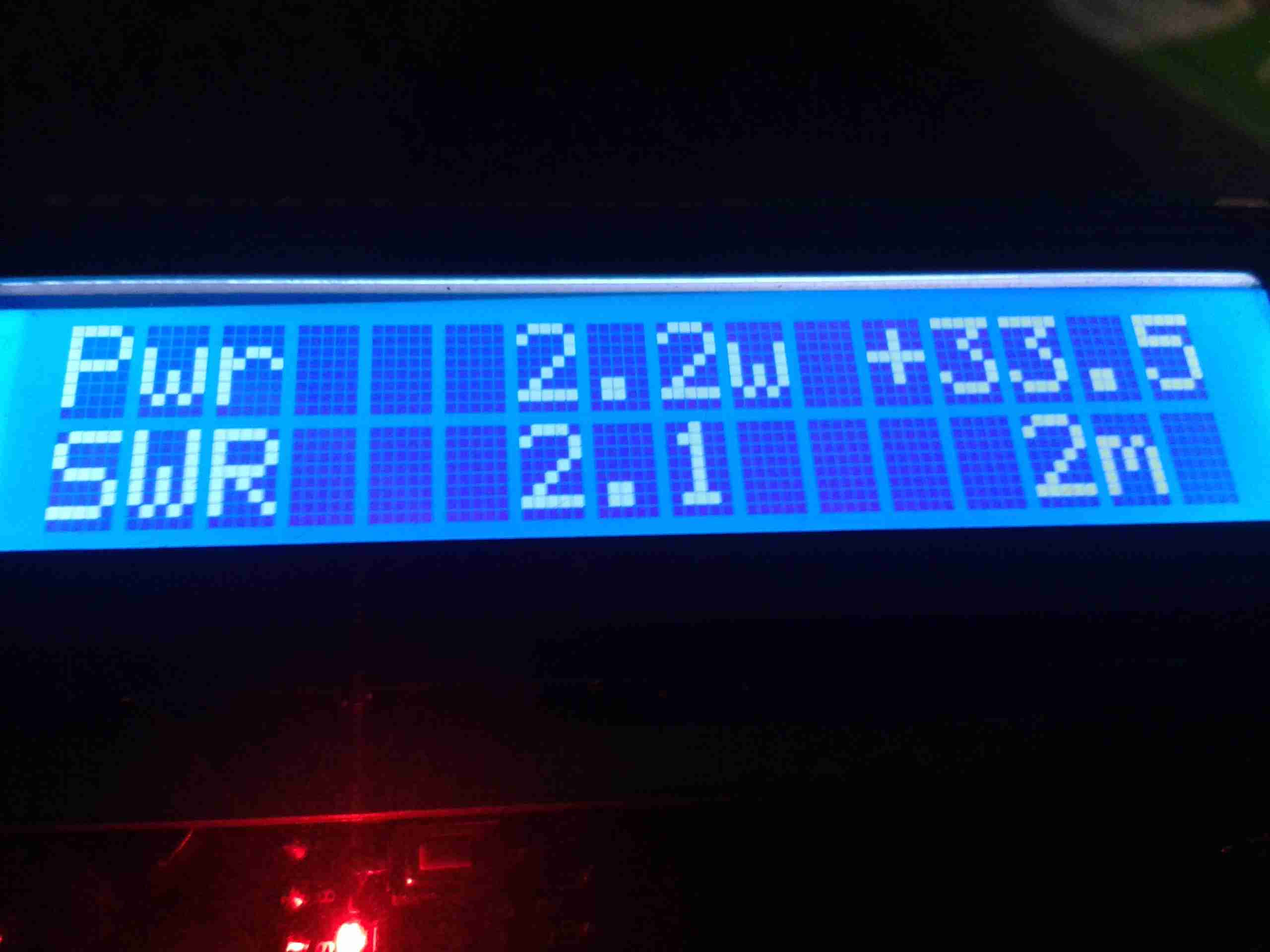
I’m using my GY561 eBay Power Meter as a calibration source, and as this isn’t perfect, the readings will be slightly off. If I can get my hands on an accurate power meter & dummy load I can always recalibrate.
Tools are only as accurate as the standard they were calibrated from!
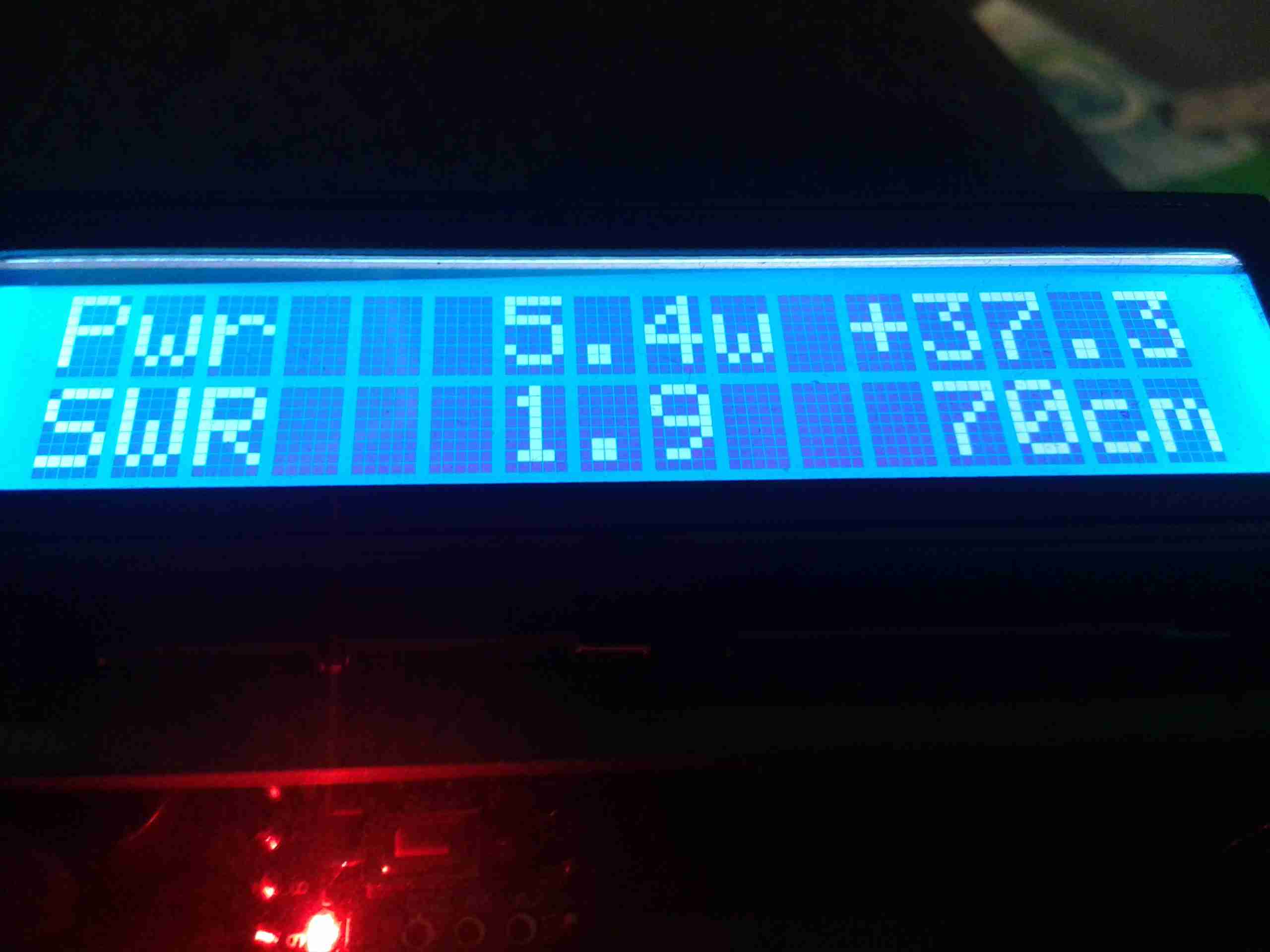
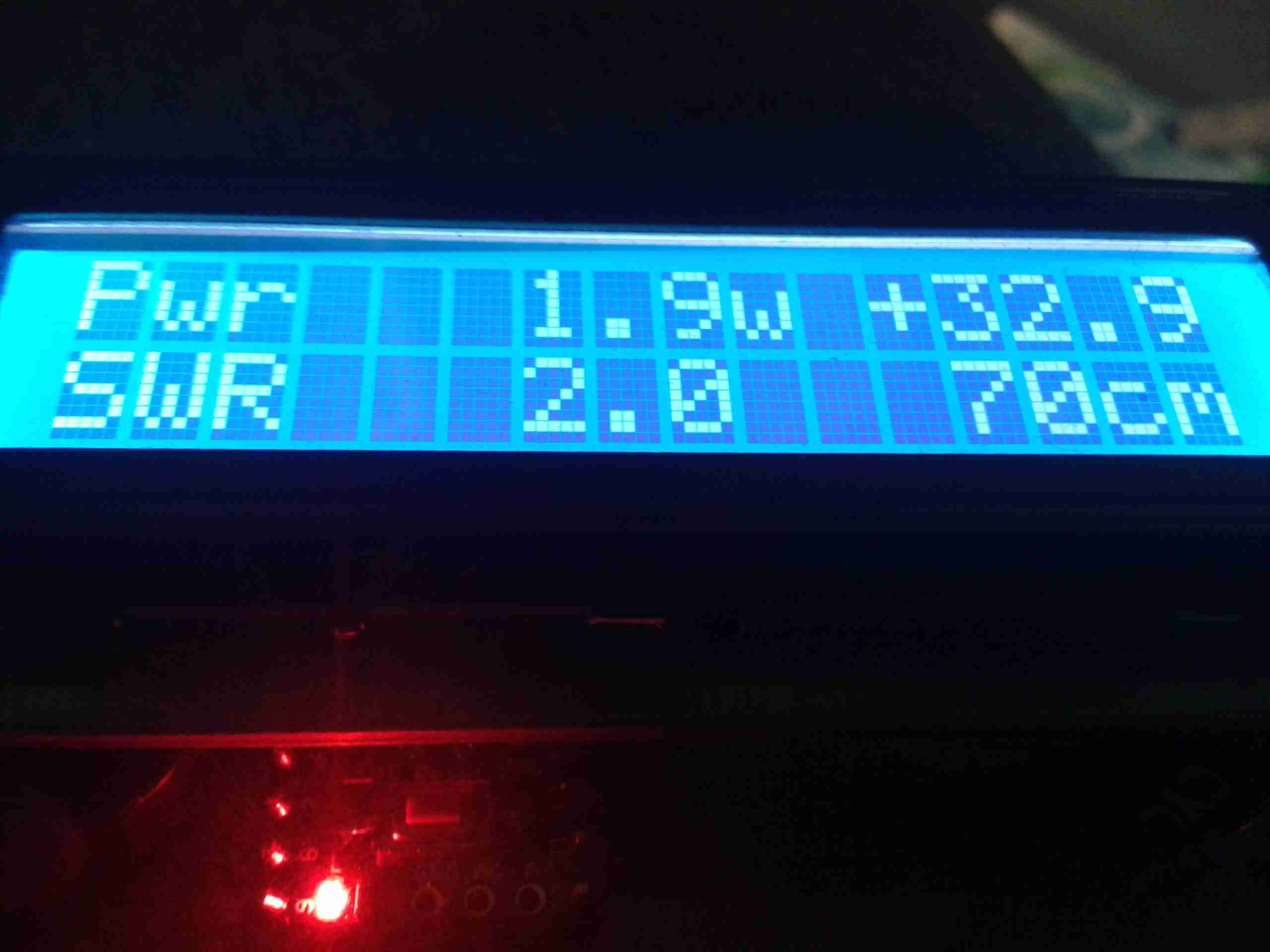
After calibration, here’s the readings on 2m & 70cm. These readings coincide nicely with the readings the GY561 produce, to within a couple tenths of a watt. SWR is more than 1:1 as the dummy load in the GY561 isn’t exactly 50Ω.
High Power VHFLow Power VHFHigh Power UHFLow Power UHF
Shortly I’ll calibrate against 6m & 10m so I can use it on every band I have access to 🙂
I recently posted about a small analog SWR/Power meter I got from eBay, and figured it needed some improvement.
After some web searching I located a project by ON7EQ, an Arduino sketch to read SWR & RF power from any SWR bridge.
The Arduino code is on the original author’s page above, his copyright restrictions forbid me to reproduce it here.
I have also noticed a small glitch in the code when it is flashed to a blank arduino: The display will show scrambled characters as if it has crashed. However pushing the buttons a few times & rebooting the Arduino seems to fix this. I think it’s related to the EEPROM being blank on a new Arduino board.
I have run a board up in Eagle for testing, shown below is the layout:
SWR Meter SCH
The Schematic is the same as is given on ON7EQ’s site. Update: ON7EQ has kindly let me know I’ve mixed up R6 & R7, so make sure they’re switched round when the board is built ;). Fitting the resistors the wrong way around may damage the µC with overvoltage.
SWR Meter PCB
Here’s the PCB layout. I’ve kept it as simple as possible with only a single link on the top side of the board.
PCB Top
Here’s the freshly completed PCB ready to rock. Arduino Pro mini sits in the center doing all the work.
The link over to A5 on the arduino can be seen here, this allows the code to detect the supply voltage, useful for battery operation.
On the right hand edge of the PCB are the pair of SMA connectors to interface with the SWR bridge. Some RF filtering is provided on the inputs.
PCB Bottom
Trackside view of the PCB. This was etched using my tweaked toner transfer method.
LCD Fitted
Here the board has it’s 16×2 LCD module.
Online
Board powered & working. Here it’s set to the 70cm band. The pair of buttons on the bottom edge of the board change bands & operating modes.
As usual, the Eagle layout files are available below, along with the libraries I use.
[download id=”5585″]
[download id=”5573″]
More to come on this when some components arrive to interface this board with the SWR bridge in the eBay meter.
Tip Jar
If you’ve found my content useful, please consider leaving a donation by clicking the Tip Jar below!
All collected funds go towards new content & the costs of keeping the server online.