Since my new Wouxun has audio output jacks, I figured it would be useful to have the ability to record what my rig hears, if anything interesting comes on the air.
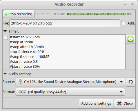
Under Linux, I use an application called, (creatively enough), Audio Recorder.
Recorder Screenshot
Using a simple connection to the mic input on a USB soundcard, I can capture everything the radio hears. Unfortunately this doesn’t work for outgoing audio, so it’s not much good at capture of my personal QSOs. For this I will have to set up another radio to act as the main receiver.
At some point in the future I will implement this with a Raspberry Pi as the audio capture server.
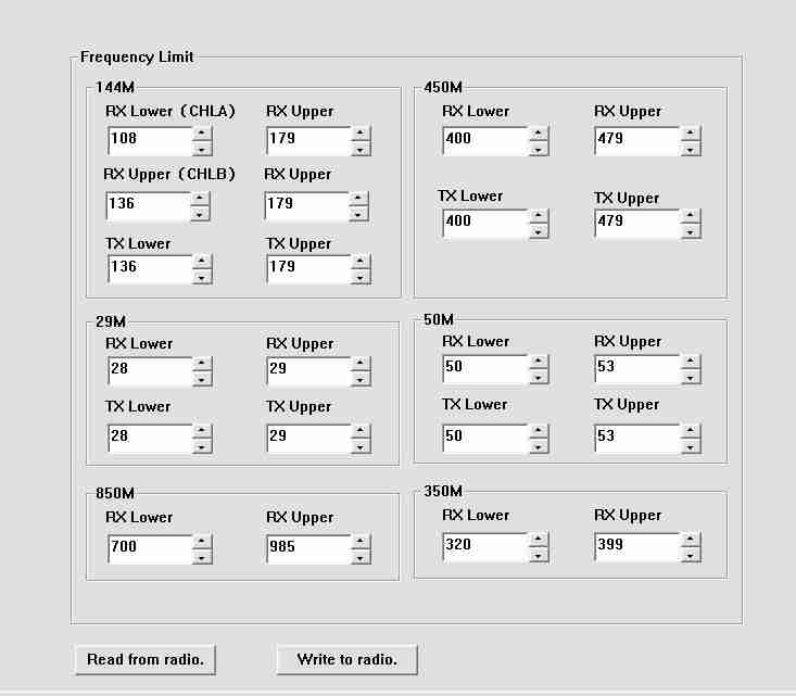
This possibly has the potential to damage the radio, if you transmit on a frequency it’s not designed for. Not to mention the legal issues with transmitting on frequencies that aren’t permitted! Use at your own risk!
I recently posted about a small analog SWR/Power meter I got from eBay, and figured it needed some improvement.
After some web searching I located a project by ON7EQ, an Arduino sketch to read SWR & RF power from any SWR bridge.
The Arduino code is on the original author’s page above, his copyright restrictions forbid me to reproduce it here.
I have also noticed a small glitch in the code when it is flashed to a blank arduino: The display will show scrambled characters as if it has crashed. However pushing the buttons a few times & rebooting the Arduino seems to fix this. I think it’s related to the EEPROM being blank on a new Arduino board.
I have run a board up in Eagle for testing, shown below is the layout:
SWR Meter SCH
The Schematic is the same as is given on ON7EQ’s site. Update: ON7EQ has kindly let me know I’ve mixed up R6 & R7, so make sure they’re switched round when the board is built ;). Fitting the resistors the wrong way around may damage the µC with overvoltage.
SWR Meter PCB
Here’s the PCB layout. I’ve kept it as simple as possible with only a single link on the top side of the board.
PCB Top
Here’s the freshly completed PCB ready to rock. Arduino Pro mini sits in the center doing all the work.
The link over to A5 on the arduino can be seen here, this allows the code to detect the supply voltage, useful for battery operation.
On the right hand edge of the PCB are the pair of SMA connectors to interface with the SWR bridge. Some RF filtering is provided on the inputs.
PCB Bottom
Trackside view of the PCB. This was etched using my tweaked toner transfer method.
LCD Fitted
Here the board has it’s 16×2 LCD module.
Online
Board powered & working. Here it’s set to the 70cm band. The pair of buttons on the bottom edge of the board change bands & operating modes.
As usual, the Eagle layout files are available below, along with the libraries I use.
[download id=”5585″]
[download id=”5573″]
More to come on this when some components arrive to interface this board with the SWR bridge in the eBay meter.
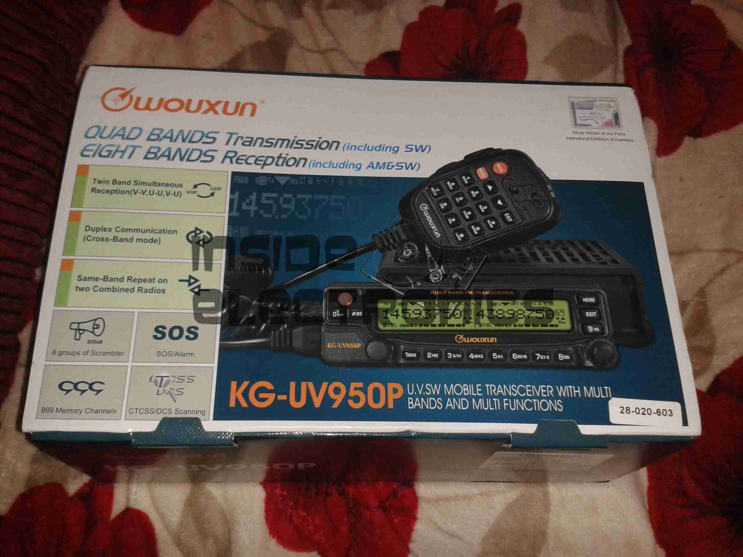
After running on handies for all of my Ameteur Radio life, I figured it was time for a new radio, this time a base station/mobile rig, & after some looking around I decided on the Wouxun KG-UV950P.
Shown below is the radio as delivered:
Wouxun Boxed
This radio has the capability to transmit quad-band, on 6m, 10m, 2m & 70cm. It also has the capability to receive on no fewer than eight bands. Also included in the feature set is airband receive, & broadcast FM receive.
TX power is up to 50W on 2m, 40W on 70cm, & 10W on 6m/10m.
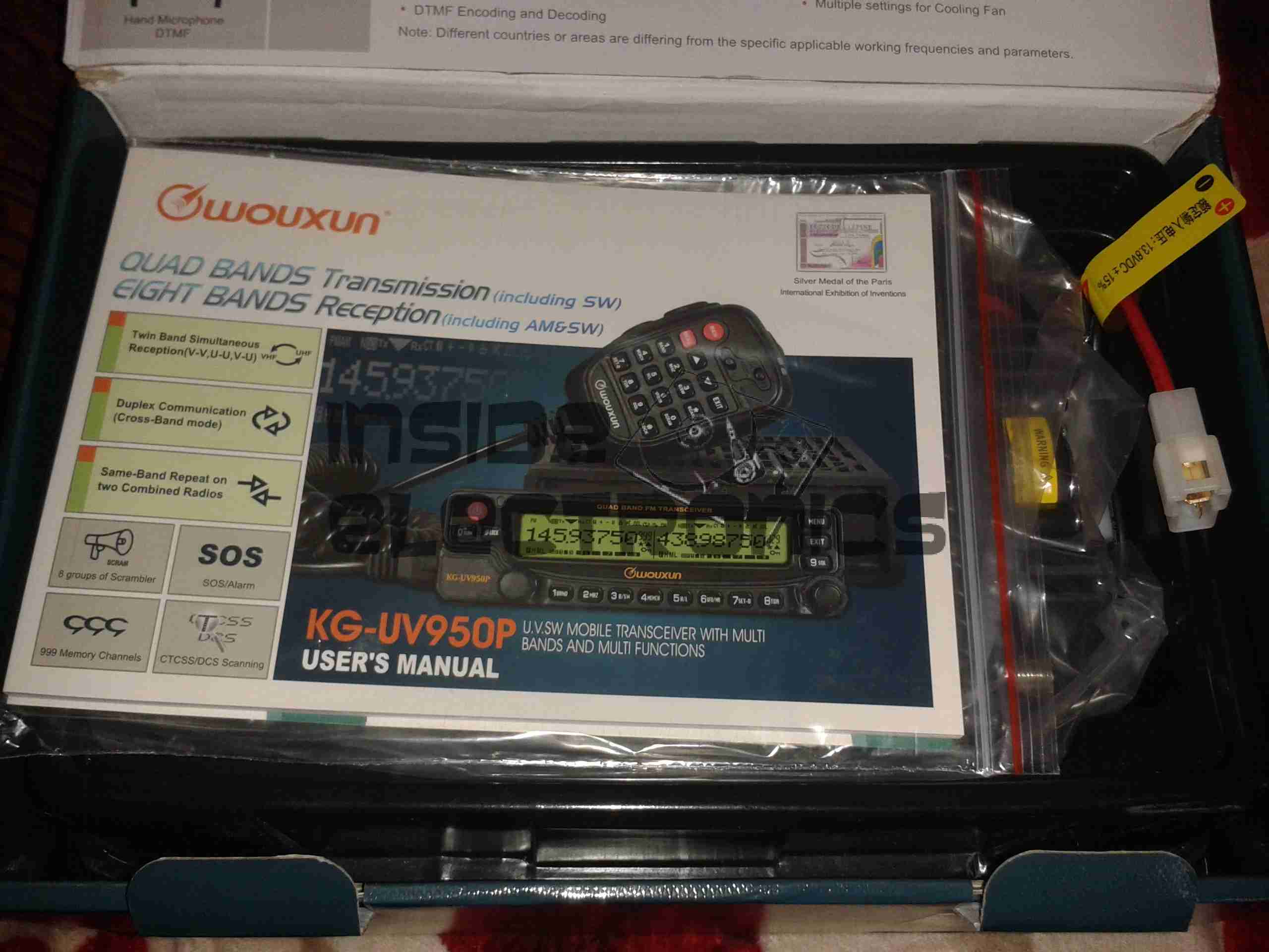
Opened
For once with a Chinese piece of electronic equipment, the manual is very well printed, and in very good English.
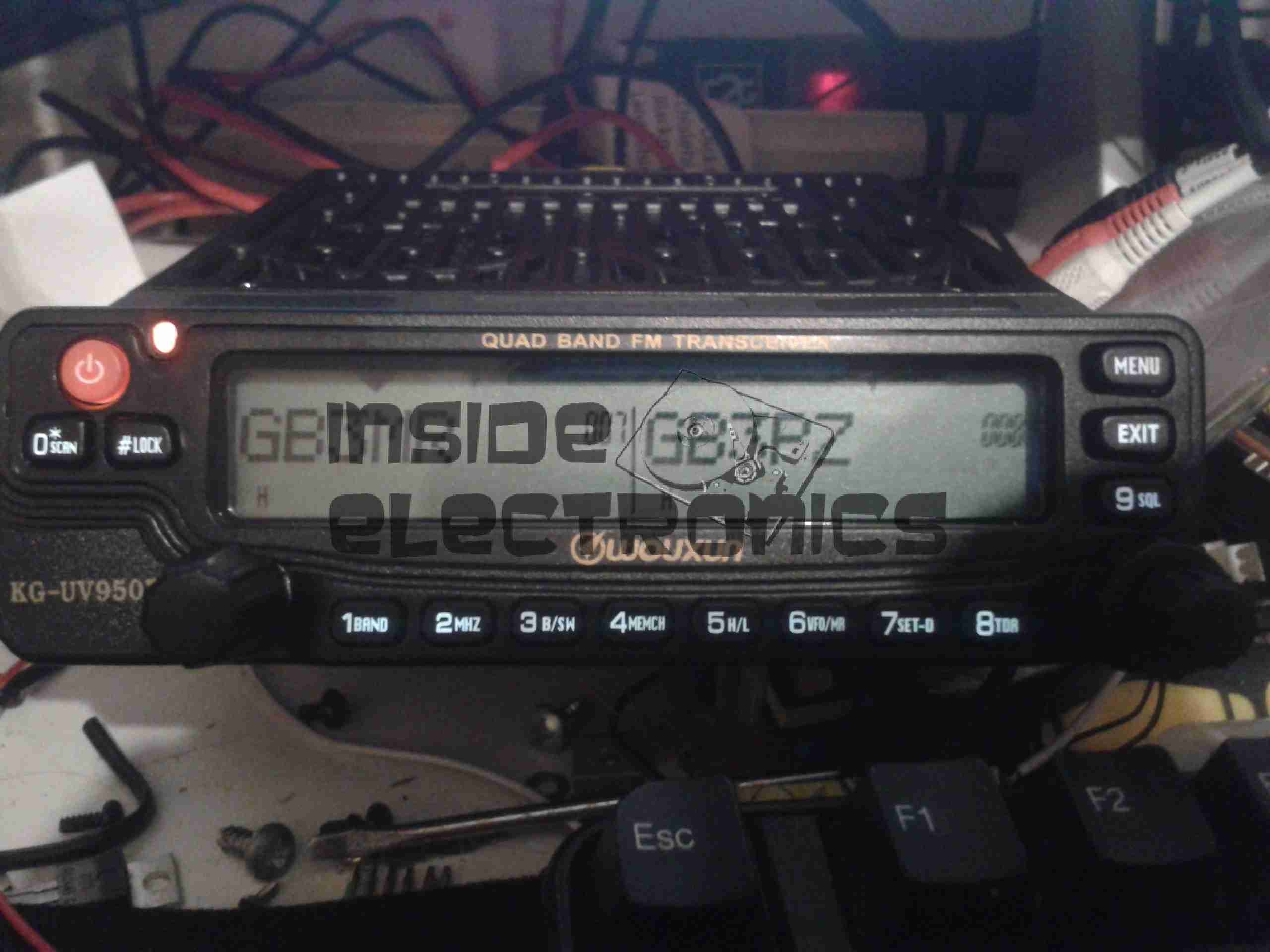
Radio Operating
Here is the radio in operation, connected to my 65A 12v power supply. I have the radio set here monitoring a couple of the local 70cm repeaters.
The display is nice & large – easy to see at a glance which station you’re tuned to. The backlight is also software settable to different colours.
Status indicators on the top edge of the display can be a bit difficult to see unless the panel is directly facing the user though, not to mention that they are rather small.
This radio is true dual-watch, in that both VFOs can be receiving at the same time, this is effected by a pair of speakers on the top panel:
Speakers
The left VFO speaker is smaller than the right, so the sound levels differ slightly, but overall sound quality is excellent. There is also provision on the back of the unit to connect external speakers.
The dual volume controls on the right hand bottom corner of the control panel are fairly decent, if a little twitchy at times. There is also a fair amount of distortion on the audio at the higher volume levels.
The controls themselves are potentiometers, but the controller appears to read the setpoint with an ADC – this means that if the control is set to just the right point, the selected level will jump around on the display & never settle down.
The radio itself is built from a solid aluminium casting, mostly for heatsinking of the main RF output stage MOSFETs. This gives the radio a very rugged construction.
A small fan is provided on the rear for cooling when required. This can be set in software to either be constantly running, (it’s pretty much silent, so this is advantageous), or only run when in TX mode. The fan will also automatically come on when a high internal temperature is detected.
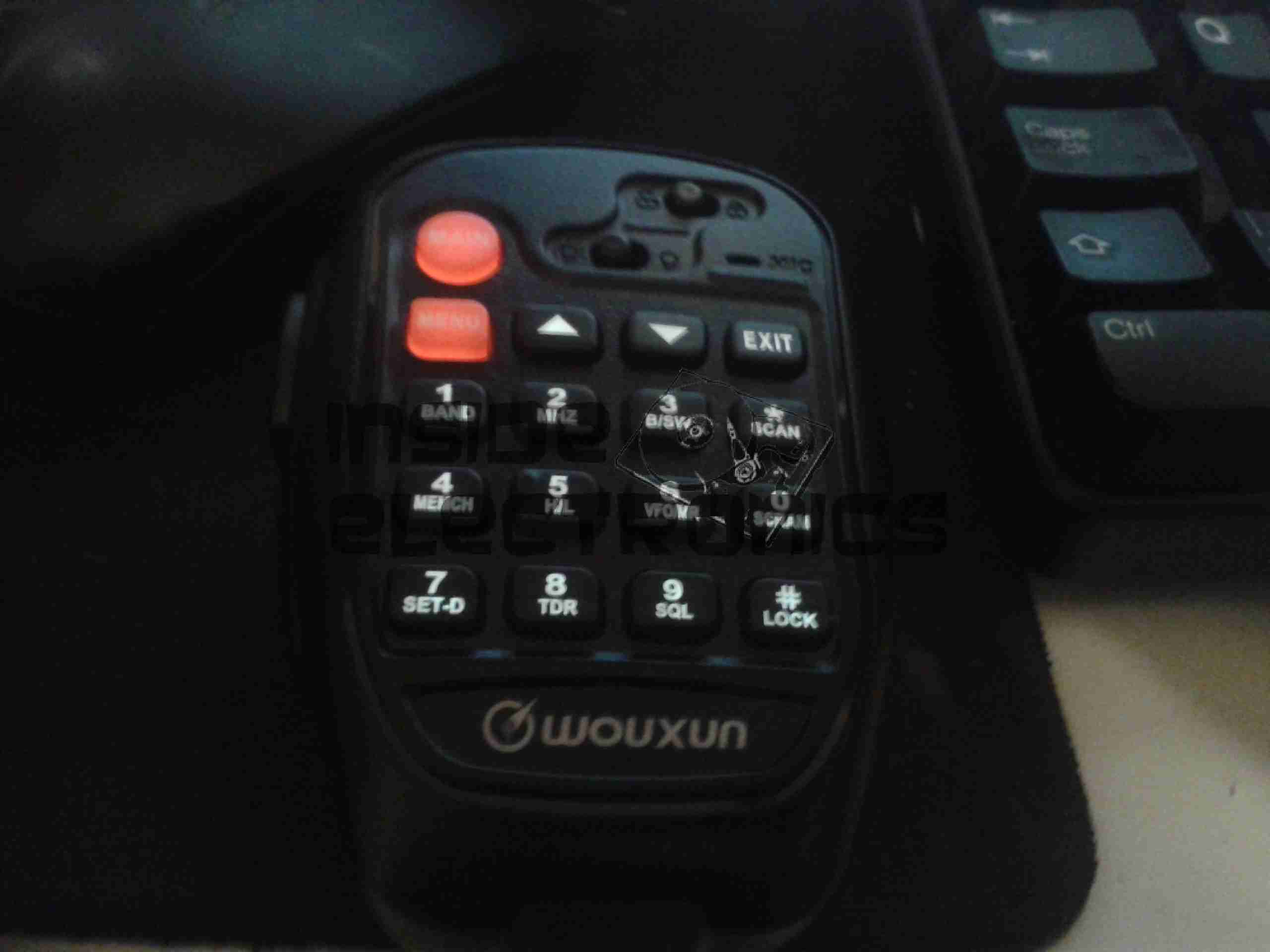
Hand Mic
Here is the microphone. Like the main unit of the radio this is also very solidly built, fits nicely in the hand & the PTT has a nice easy action, which helps to prevent straining hands while keeping the TX keyed.
Conveniently, all of the controls required to operate the radio are duplicated on this mic, along with a control lock switch, & backlighting for the buttons.
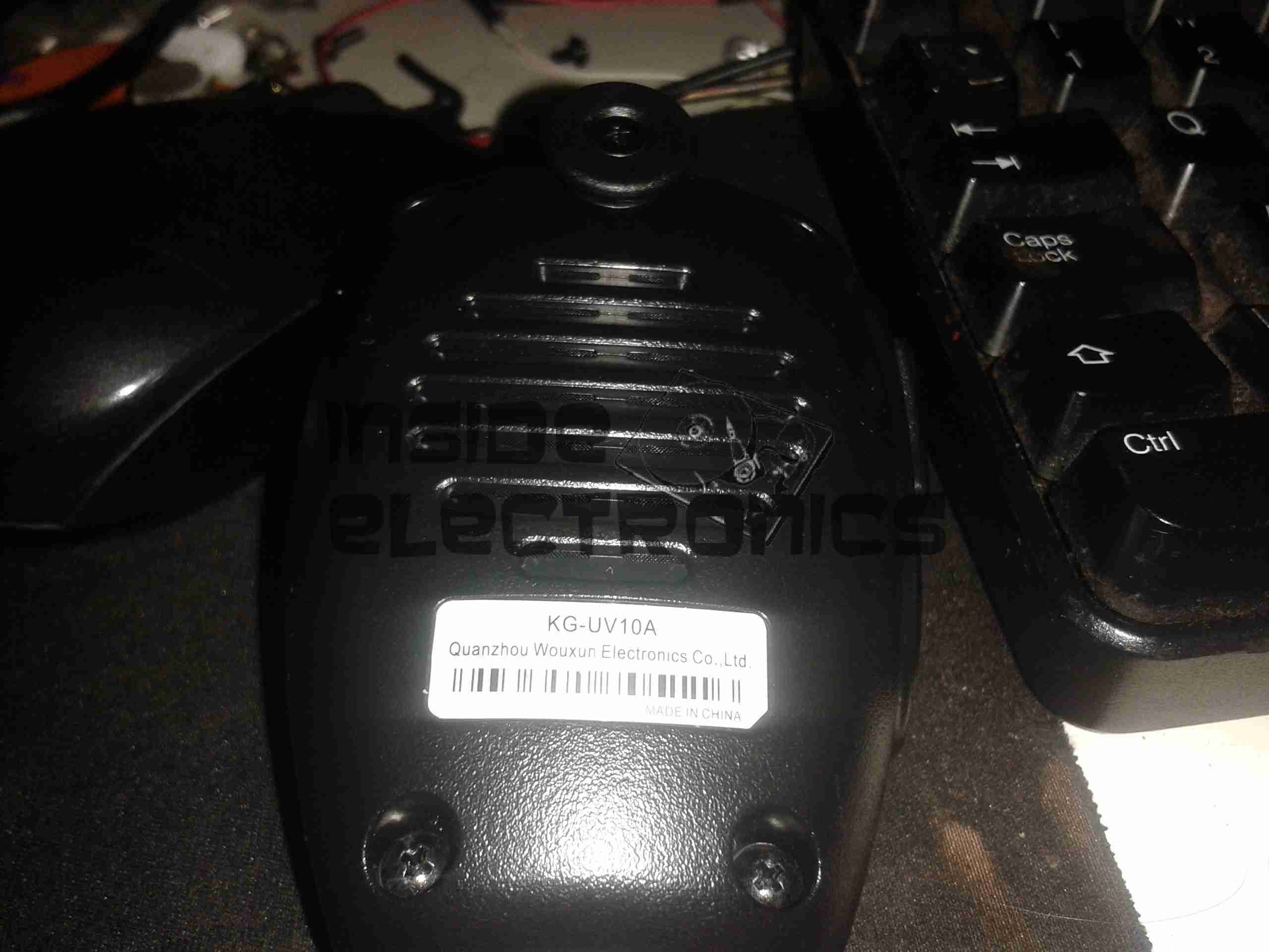
Another Speaker
Another output speaker is placed in the back of the mic. This one can be activated through the menu system, to either use the main body speakers, the mic mounted one, or both.
A mounting hook for the mic is provided to attach to any convenient surface.
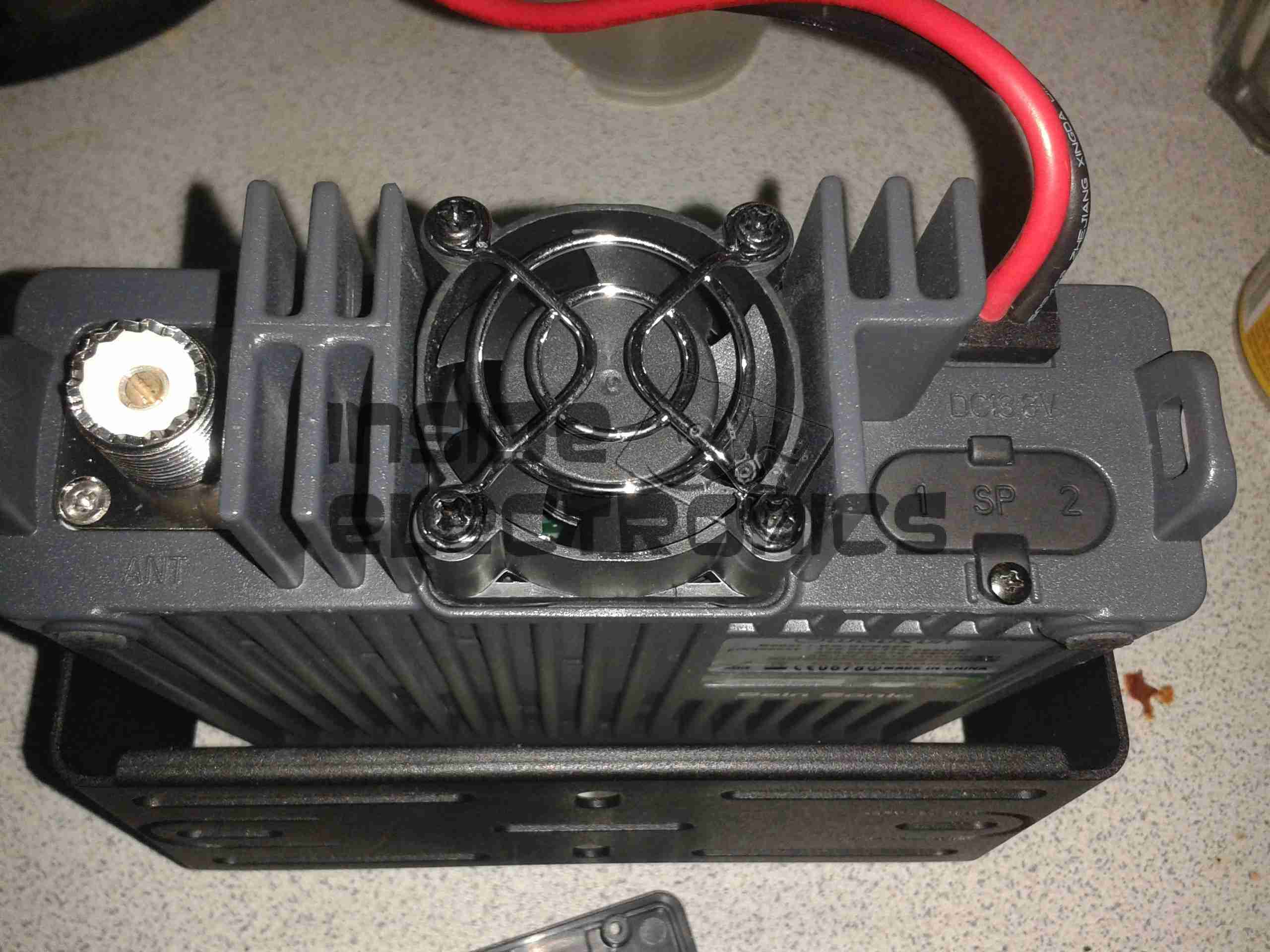
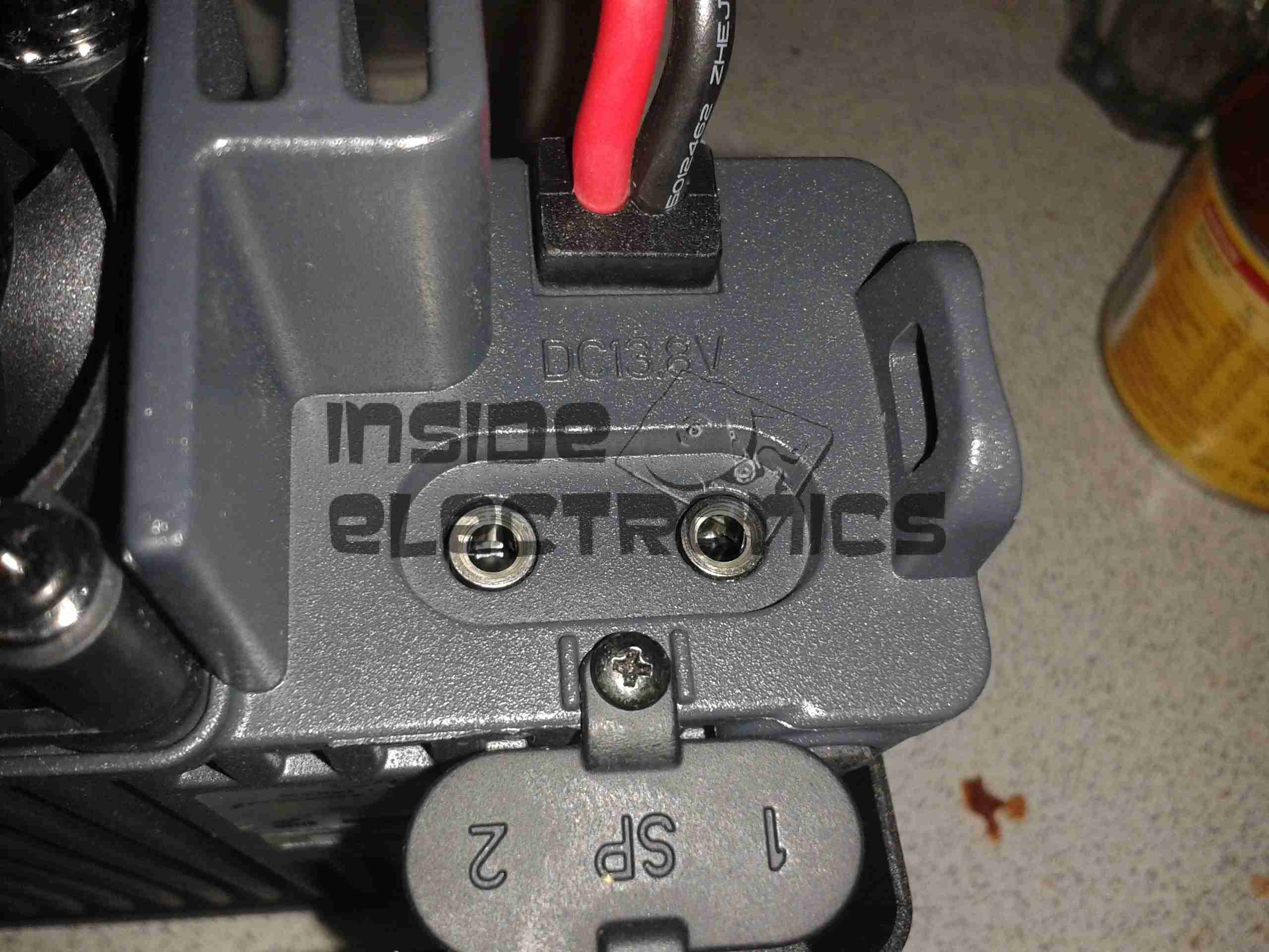
Radio Back
Here’s the back of the radio, with some of the big heatsink fins, the fan in the centre. To the left is the PL259 RF output, this looks to be a high quality Teflon insulated one. On the right are the power input leads & the external speaker outputs.
External Speaker Sockets
The external speaker connections are via 3.5mm jacks. I haven’t yet tested this feature.
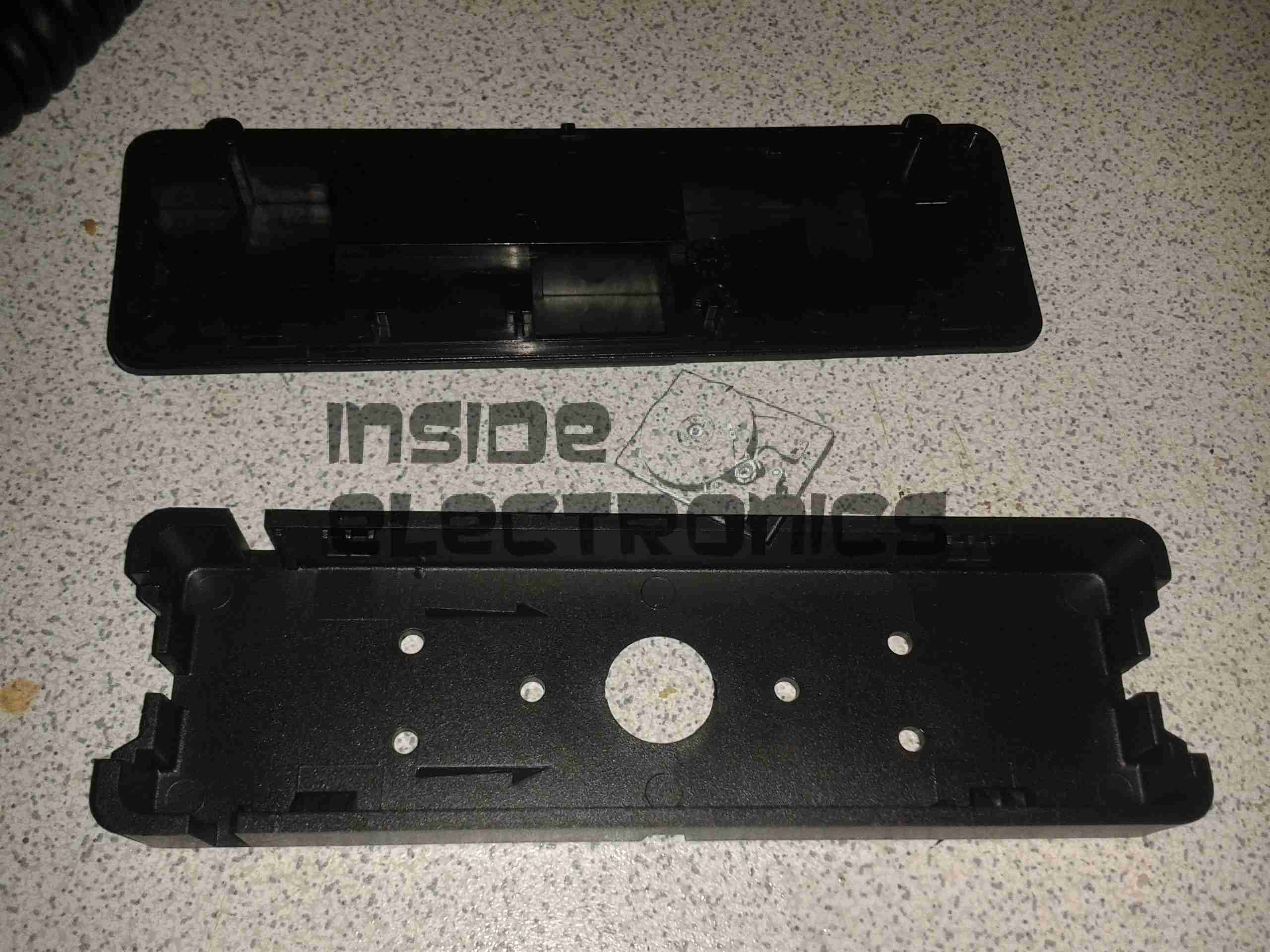
Remote Mounting Plate
The control panel of this radio is detachable from the main body, and a pair of adaptors are provided. This either allows the radio display to be angled upwards toward the user, set parallel, or even mounted remotely. A control extension cable is provided to allow the main body to be mounted a fair distance away.
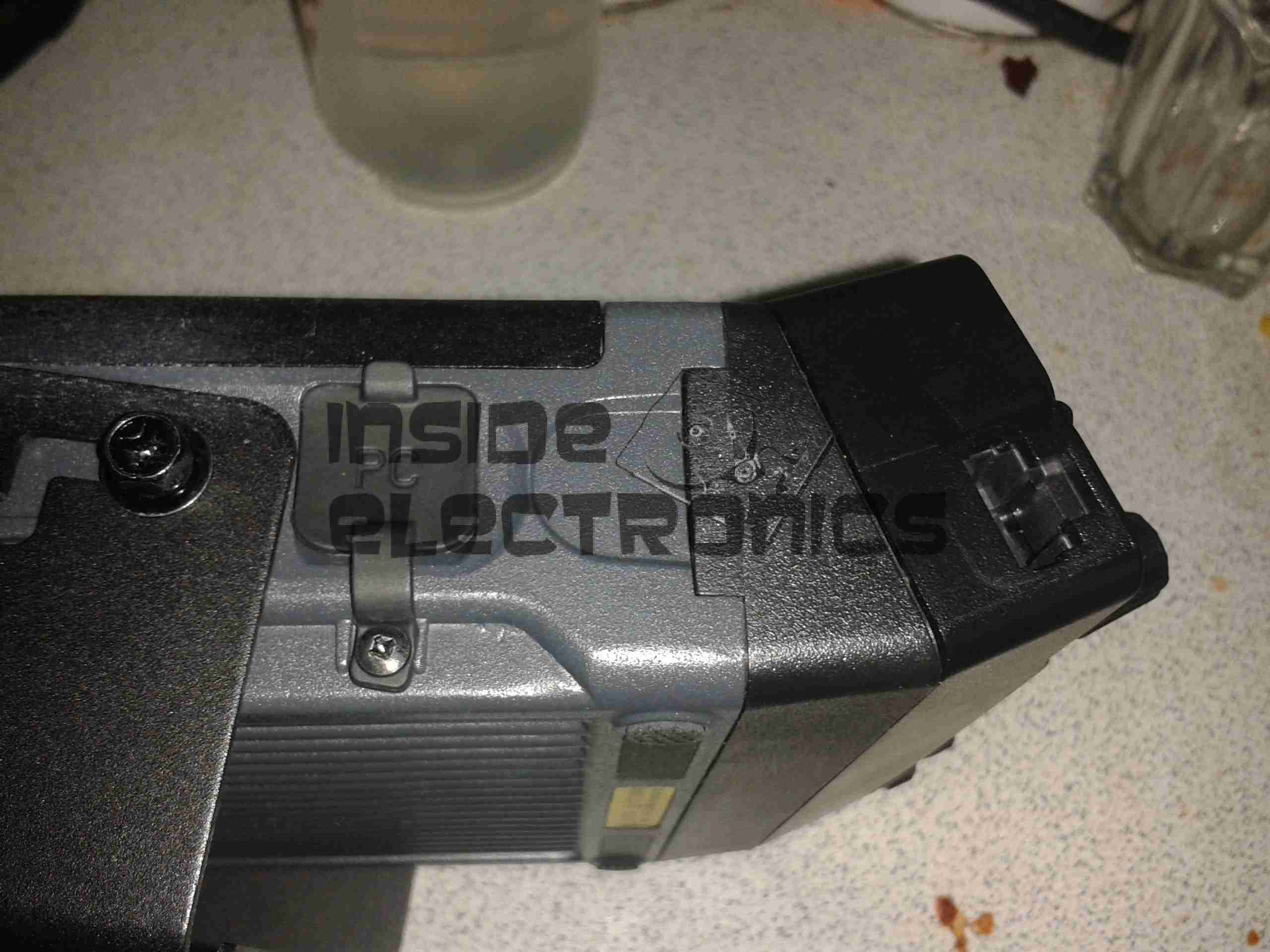
External Interface Connectors
On the left of the radio is the PC control & programming port, & the mic connector. Wouxun *really* like RJ-45 connectors, they’ve used them for everything on this radio.
Also visible here is the tilted faceplate adaptor.
The supplied software to program the radio, while functional, is absolutely horrific. Hopefully someone will add support for this radio into CHIRP. Anything would be an improvement in this area.
Everything considered, I like this radio. It’s very solidly built, easy to use, and sounds brilliant.
TX audio is great, (or so my other contacts tell me).
Unsurprisingly, the unit gets warm while transmitting, however on high power, it does get uncomfortably warm, and the built in fan does little in the way of helping when a long QSO is in progress. I may remedy this at some stage with a more powerful fan. A little more airflow would do wonders.
If the programming software was built as well as the radio, I’d have zero serious complaints.
At full power, the radio pulls ~10A from the power supply, at 12.9v DC.
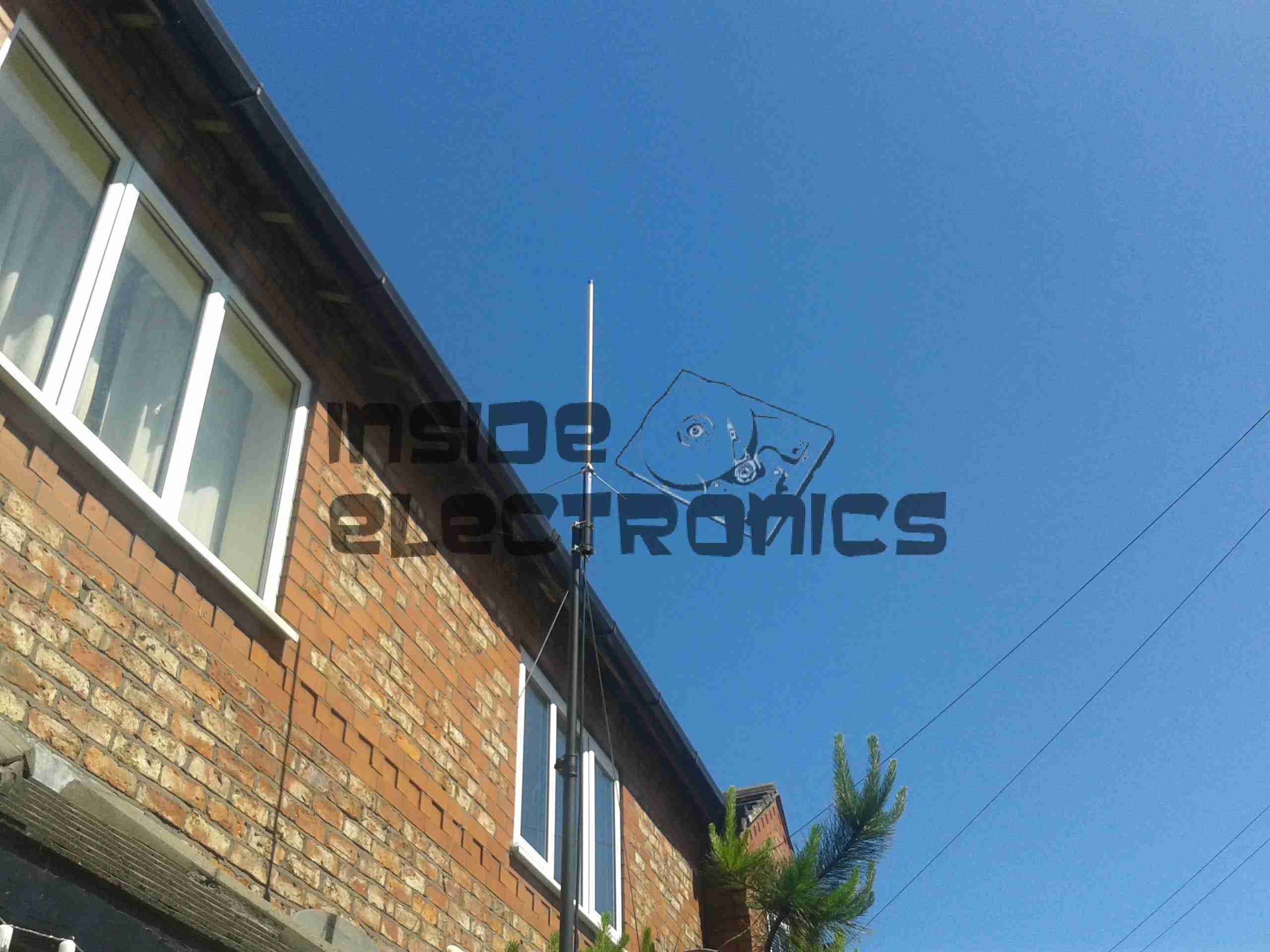
As for the antenna I’m currently using, it’s a Diamond X30, mounted on a modified PA speaker stand, at ~30 feet above ground. The feeder is high quality RG-213.
TX Antenna
When I manage to get the set disconnected, a partial teardown will be posted, with some intimate details about the internals. Stay tuned!
Continuing from my previous post where I published an Eagle design layout for AD7C‘s Arduino powered VFO, here is a completed board.
I have made some alterations to the design since posting, which are reflected in the artwork download in that post, mainly due to Eagle having a slight psychotic episode making me ground one of the display control signals!
AD9850 VFO
The amplifier section is unpopulated & bypassed as I was getting some bad distortion effects from that section, some more work is needed there.
The Arduino Pro Mini is situated under the display, and the 5v rail is provided by the LM7805 on the lower left corner.
Current draw at 12v input is 150mA, for a power of 1.8W total. About 1W of this is dissipated in the LM7805 regulator, so I have also done a layout with an LM2574 Switching Regulator.
The SMPS version should draw a lot let power, as less is being dissipated in the power supply, but this version is more complex.
DDS VFO-SMPS
Here the SMPS circuit can be seen on the left hand side of the board, completely replacing the linear regulator.
I have not yet built this design, so I don’t know what kind of effect this will have on the output signal, versus the linear regulator. I have a feeling that the switching frequency of the LM2574 (52kHz) might produce some interference on the output of the DDS module. However I have designed this section to the standards in the datasheet, so this should be minimal.
Nevertheless this version is included in the Downloads section at the bottom of this post.
The output coupled through a 100nF capacitor is very clean, as can be seen below, outputting a 1kHz signal. Oscilloscope scale is 0.5ms/div & 1V/div.
VFO Output (Mucky ‘Scope)Scope Connected
Thanks again to Rich over at AD7C for the very useful tool design!
Linked below is the Eagle design files for this project, along with my libraries used to create it.
After passing my Foundation course on the 1st December, I have finally received my certificate & obtained my licence!
Certificate
My new callsign is M6GCY. Time to get on the air!
Tip Jar
If you’ve found my content useful, please consider leaving a donation by clicking the Tip Jar below!
All collected funds go towards new content & the costs of keeping the server online.