Posted on Leave a comment

300th Post! Site Updates, News, Etc

Since this is the 300th post on my blog in the 6 years I’ve been at this, I figured I’d do a post with recent site updates & some news.

Site Look

There haven’t been many updates to the general look of the site for quite a while, with some help of a friend I managed to get a new ticker added to the header, which saves on post count for upcoming projects & posts.
The header image is also dynamic, picking randomly from a collection of images, mostly from previous posts, and a few that started as messing about with a camera & turned out looking quite good.

Site Support

Also added to the site’s look is a Tip Jar on the right hand side, so thankful readers can donate something if I’ve managed to post something remotely helpful ;).
People that know me personally know I hate ads with a passion, and as such ads will have no place on my blog for as long as it’s visible on the intertubes. The site does cost quite a significant (to me anyway) amount of cash to keep going, not to mention time, so any donations would be more than welcome!
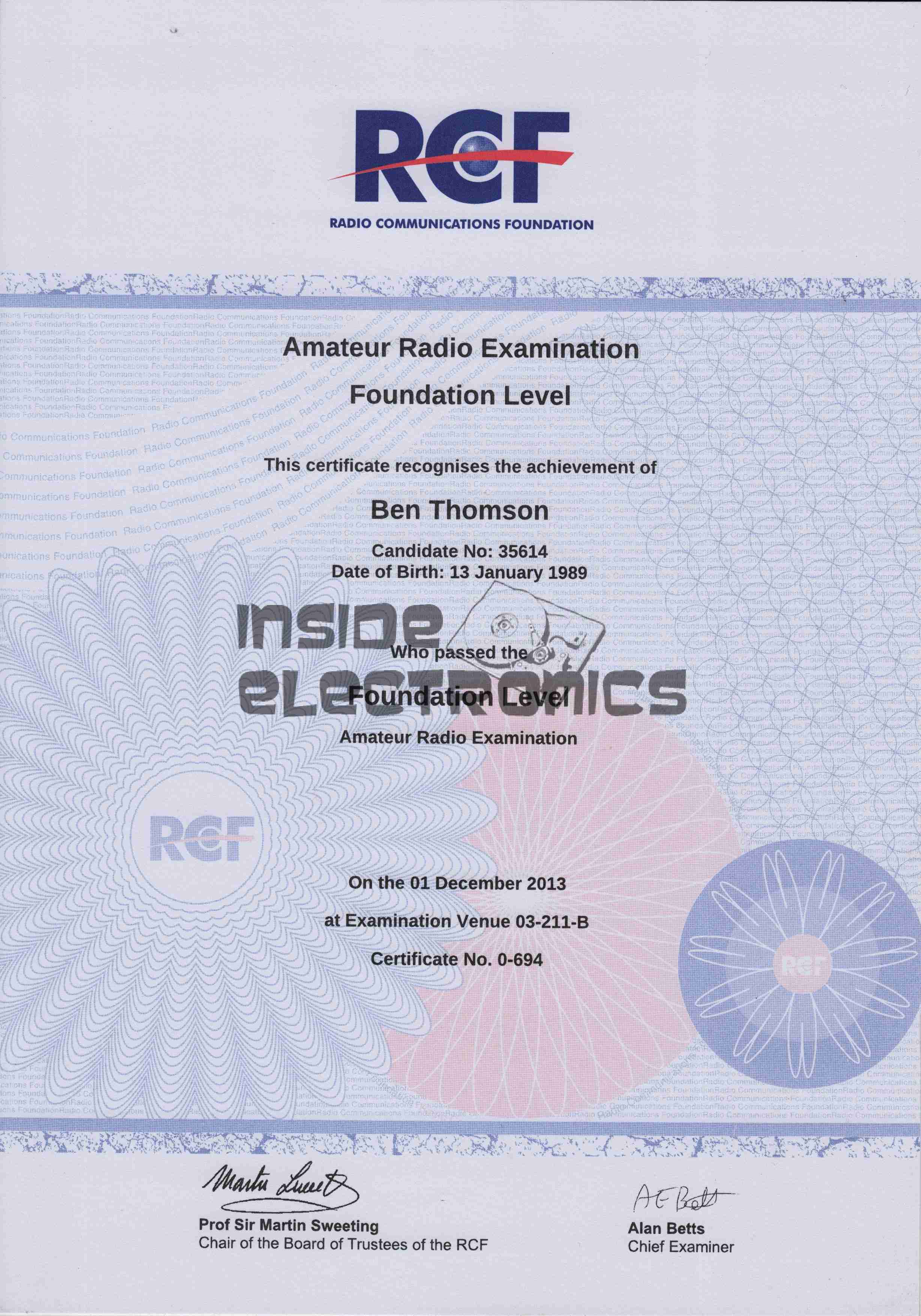
Radio-Based Posts

I haven’t done any proper Ham Radio based posts in quite a while, mainly due to me not having anything to share on the subject, unfortunately it can be a damn expensive hobby & there are other things taking priority at the moment. (Apparently eating & warmth are essentials, according to the missus at least ;)).
There is going to be a round-about radio based post shortly though, so my Ham readers stay tuned!

Boating Posts

Now that we’re in the new year, when the weather returns to something remotely tolerable to be outdoors in, there’ll be much more boating related stuff on the cards, not only trips but engineering jobs onboard.


Posted on Leave a comment

Quickie Project: Ruggedising The RTL-SDR Dongle

As supplied, the RTL type tuner dongles are a little fragile, especially when they’ve got a rather heavy coax feeder attached for Ham Radio use.

The MCX antenna connectors on the tuner can’t stand up to much abuse, and even the USB plug rips itself from it’s mounts after a while with a heavy weight on the end. Since this dongle sits in my radio go bag, it definitely needed some protection & support.

PCB
PCB

The PCB itself is removed from it’s flimsy plastic casing, the USB plug is desoldered from the board.
To the exposed pads, a USB cable is soldered, giving much more flexibility in where the tuner is placed.
Instead of using the MCX antenna connector on the PCB, the coax is stripped & soldered direct to the PCB itself, as this connector has become unreliable.

N-Connector
N-Connector

To get the RF into the device, the case is fitted with an N connector, as is everything else in my shack.

Boxed
Boxed

The box used is a surplus one which previously housed an electronic lighting transformer. This would be very easy to waterproof as well, for more protection against outdoor use.

Posted on Leave a comment

AD9850 VFO Board

Continuing from my previous post where I published an Eagle design layout for AD7C‘s Arduino powered VFO, here is a completed board.

I have made some alterations to the design since posting, which are reflected in the artwork download in that post, mainly due to Eagle having a slight psychotic episode making me ground one of the display control signals!

AD9850 VFO
AD9850 VFO

The amplifier section is unpopulated & bypassed as I was getting some bad distortion effects from that section, some more work is needed there.
The Arduino Pro Mini is situated under the display, and the 5v rail is provided by the LM7805 on the lower left corner.

Current draw at 12v input is 150mA, for a power of 1.8W total. About 1W of this is dissipated in the LM7805 regulator, so I have also done a layout with an LM2574 Switching Regulator.
The SMPS version should draw a lot let power, as less is being dissipated in the power supply, but this version is more complex.

DDS VFO-SMPS
DDS VFO-SMPS

Here the SMPS circuit can be seen on the left hand side of the board, completely replacing the linear regulator.
I have not yet built this design, so I don’t know what kind of effect this will have on the output signal, versus the linear regulator. I have a feeling that the switching frequency of the LM2574 (52kHz) might produce some interference on the output of the DDS module. However I have designed this section to the standards in the datasheet, so this should be minimal.

Nevertheless this version is included in the Downloads section at the bottom of this post.

The output coupled through a 100nF capacitor is very clean, as can be seen below, outputting a 1kHz signal. Oscilloscope scale is 0.5ms/div & 1V/div.

VFO Output
VFO Output (Mucky ‘Scope)
Scope Connected
Scope Connected


Thanks again to Rich over at AD7C for the very useful tool design!

Linked below is the Eagle design files for this project, along with my libraries used to create it.

[download id=”5571″]

[download id=”5573″]

[download id=”5575″]