Posted on Leave a comment

Pilot LPG Monitoring System

Pilot Gas Monitor
Pilot Gas Monitor

In my mind, the most dangerous thing onboard any boat is the LPG system, as the gas is heavier than air, any leaks tend to collect in the bilges, just waiting for an ignition source. To mitigate this possibility, we’re fitting a gas monitoring system that will sound an alarm & cut off the supply in case of a leak.

Monitor Unit
Monitor Unit

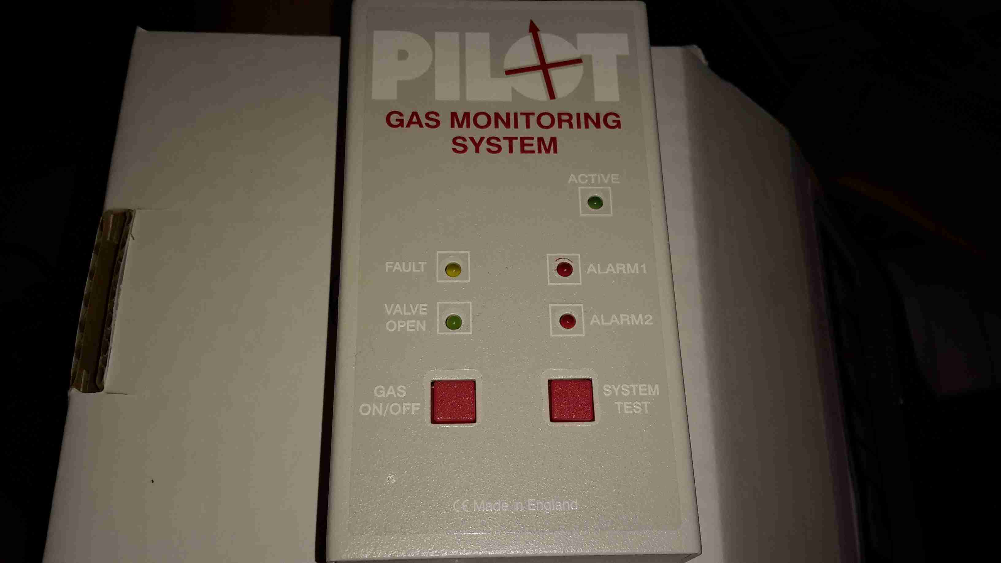
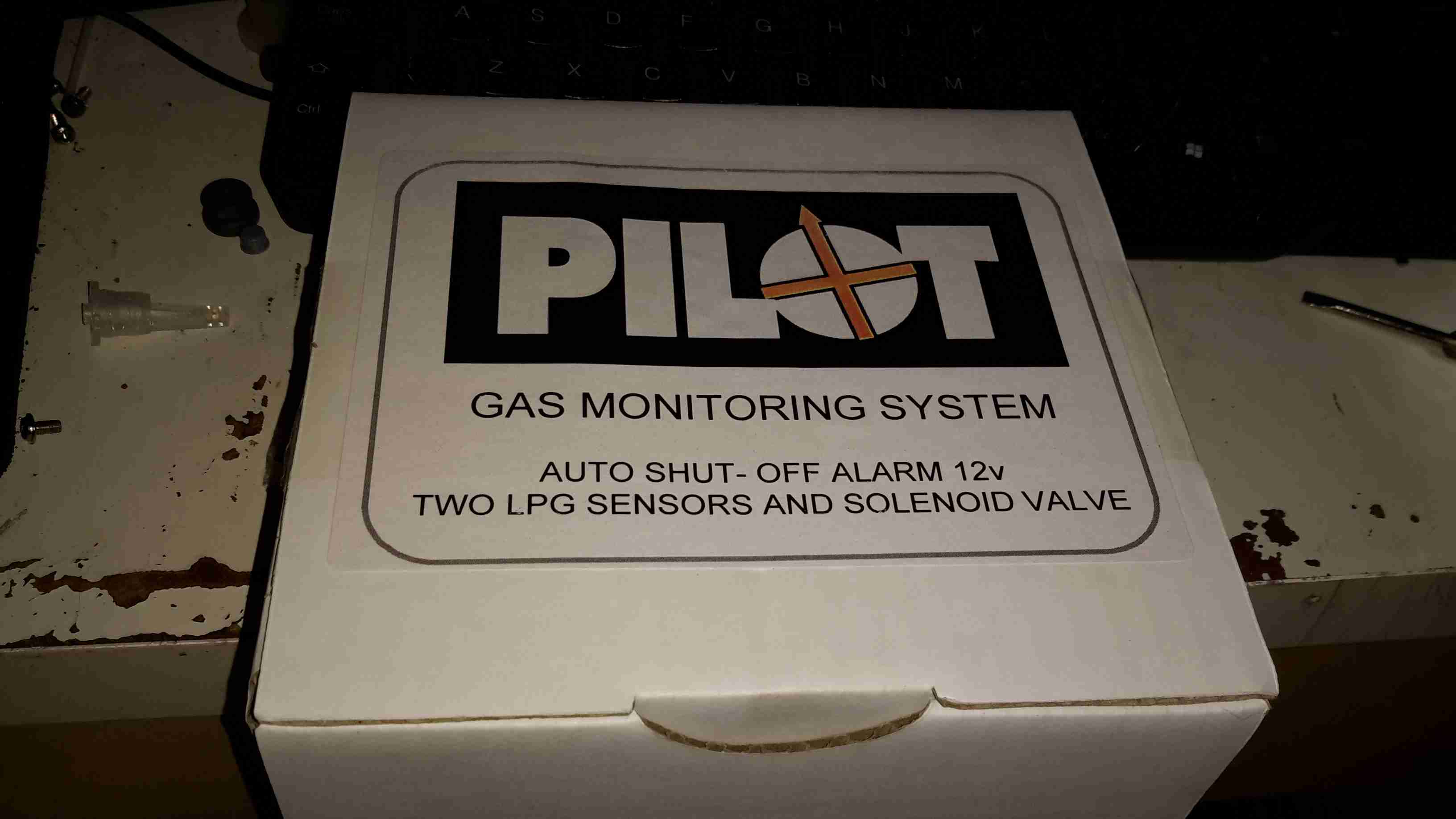
Here’s the monitor itself, the two sensor model. It’s nice & compact, and the alarm is loud enough to wake the dead.

Control Board
Control Board

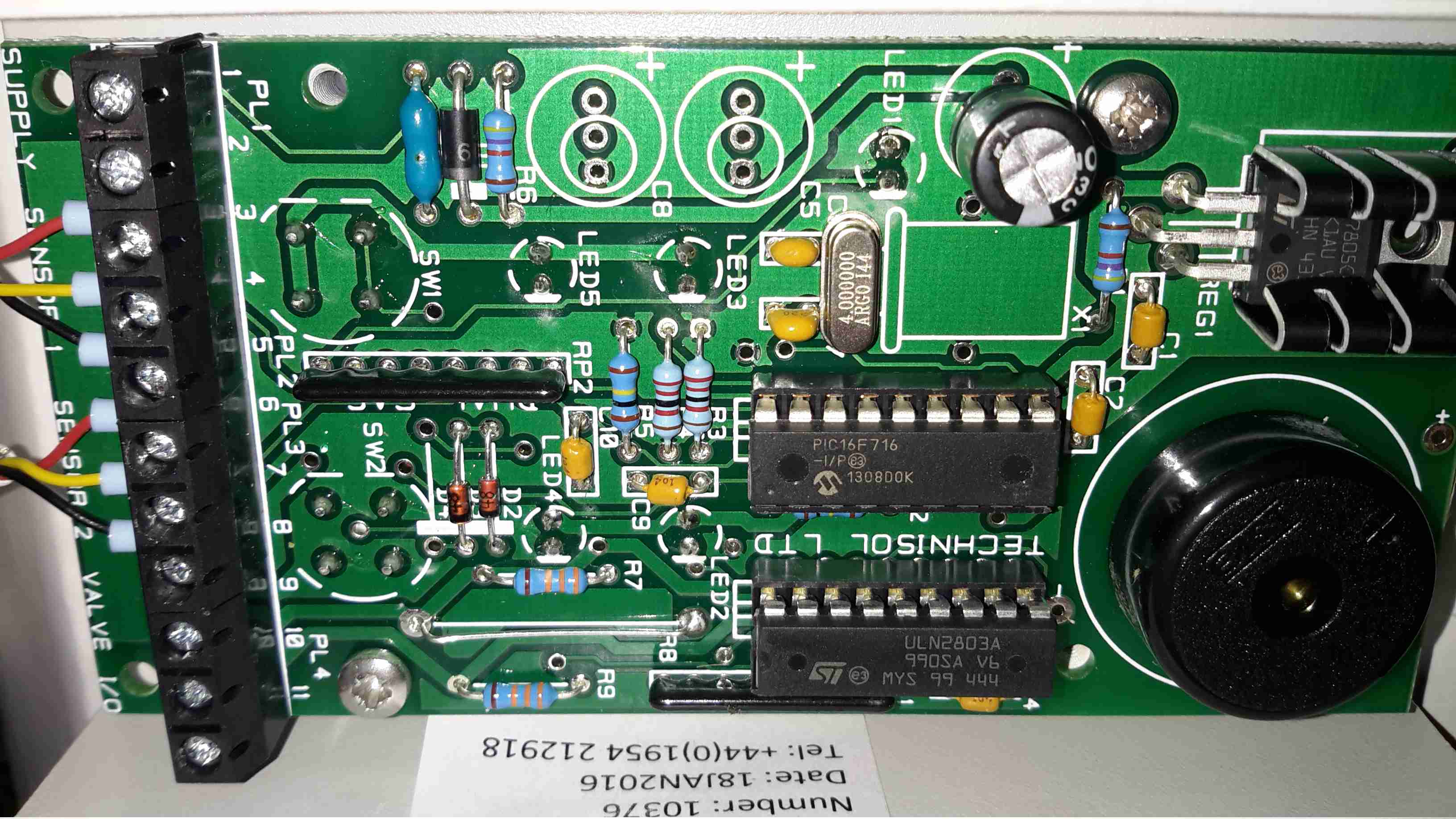
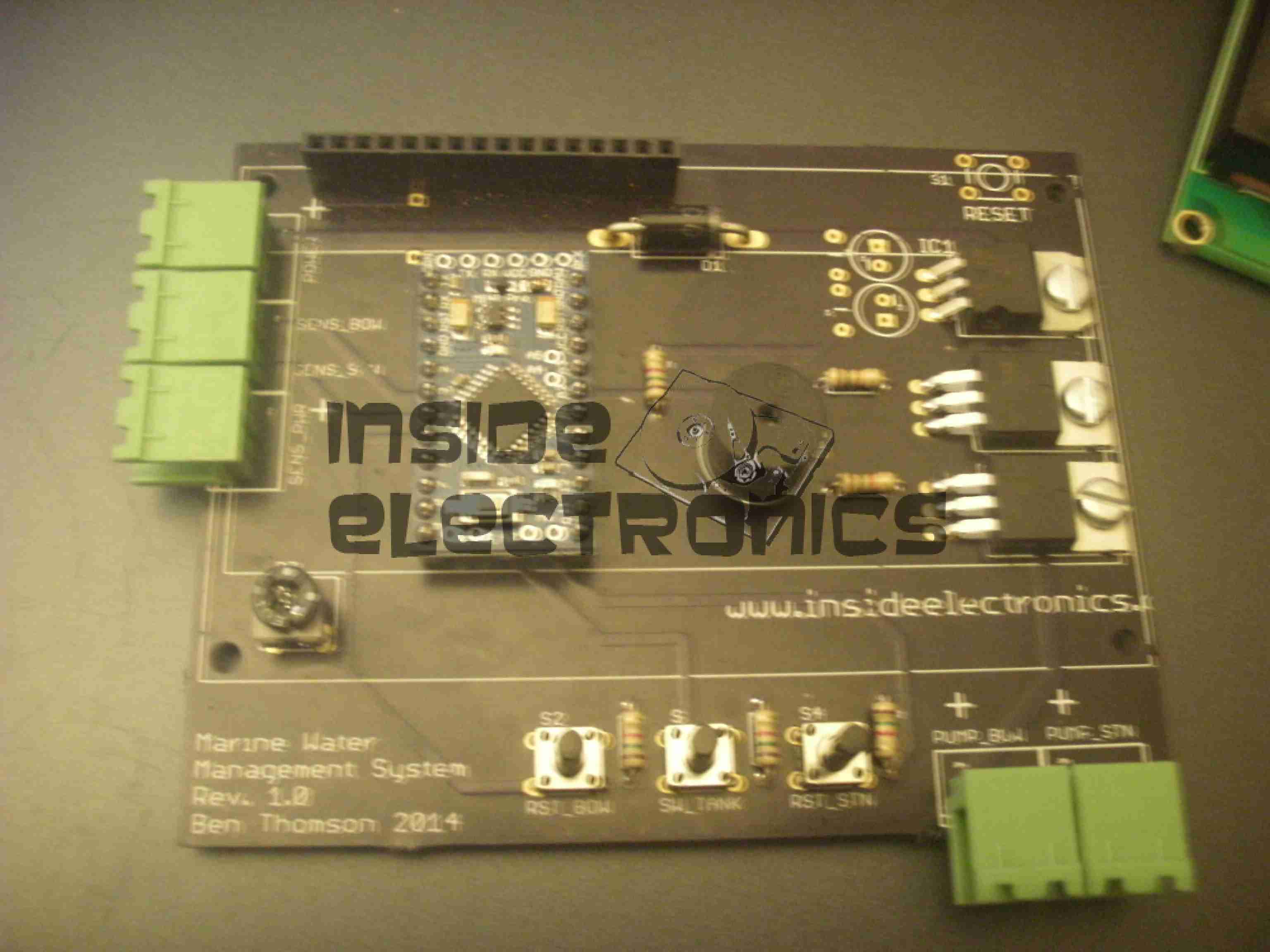
Not much inside in the way of circuitry, the brains of the operation is a Microchip PIC16F716 8-bit microcontroller with an onboard A/D converter (needed to interface with the sensors), running at 4MHz. The solenoid valve is driven with a ULN2803 Darlington transistor array.
The alarm Piezo sounder can be seen to the right of the ICs, above that is a simple LM7805 linear regulator providing power to the electronics.

Remote Sensor
Remote Sensor

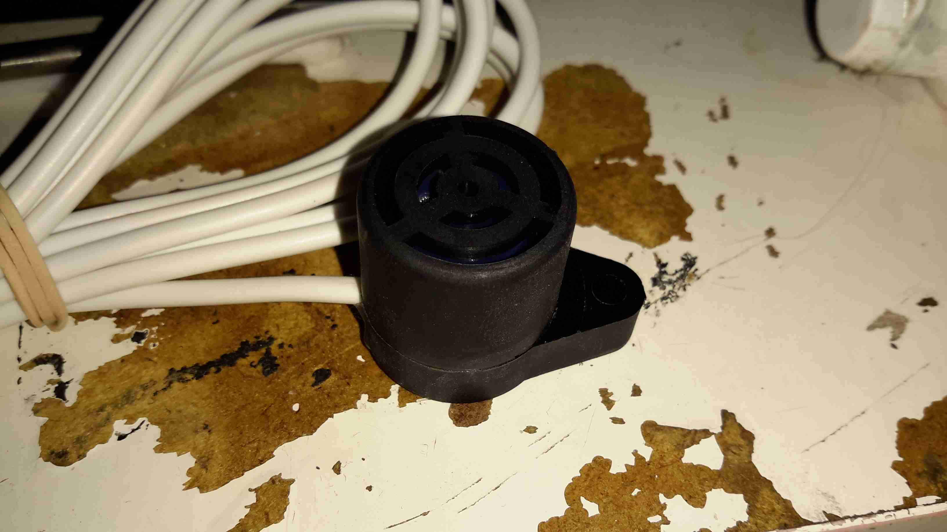
The pair of remote sensors come with 3.5m of cable, a good thing since the mounting points for these are going to be rather far from the main unit in our installation.

Sensor Element
Sensor Element

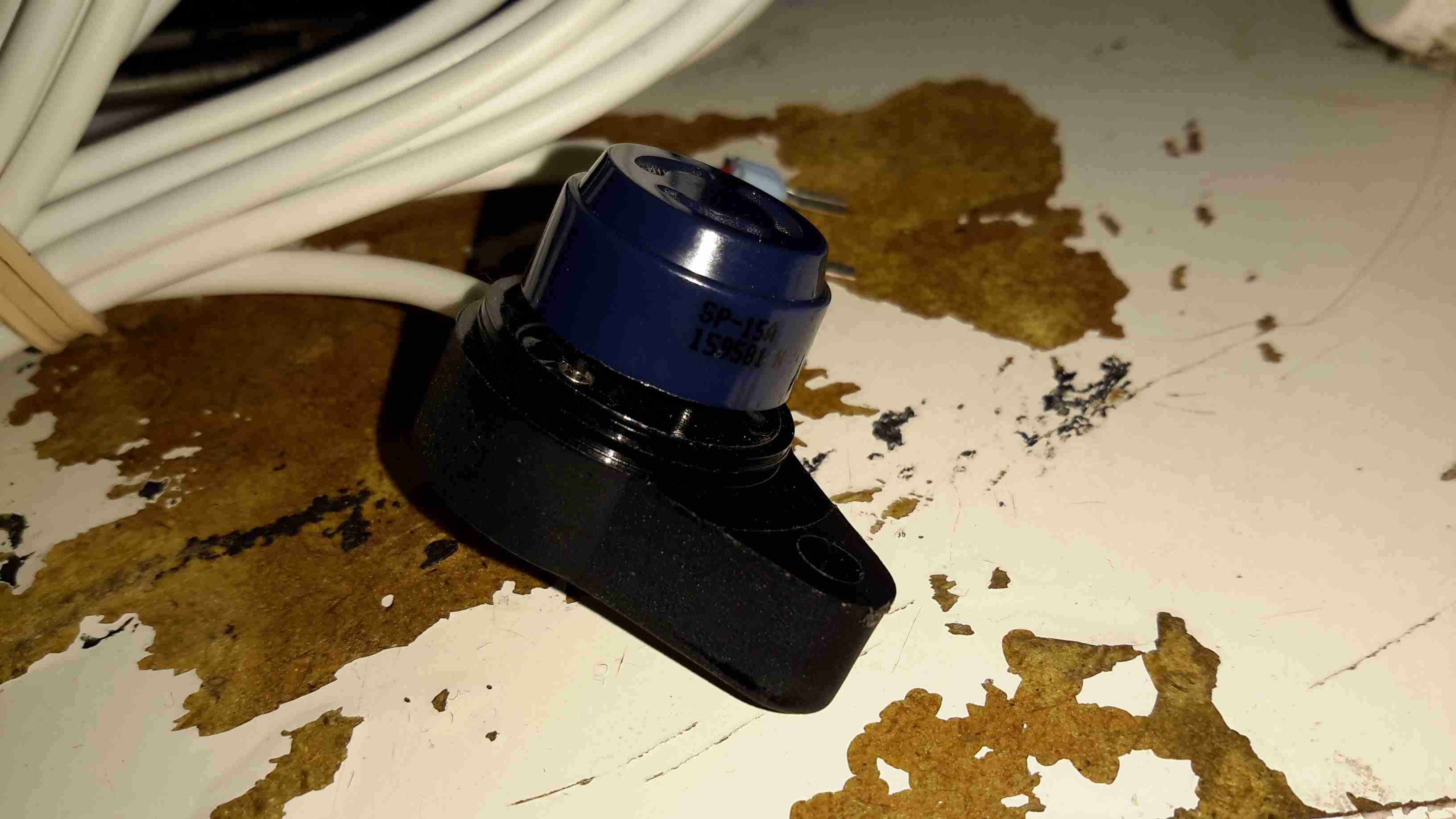
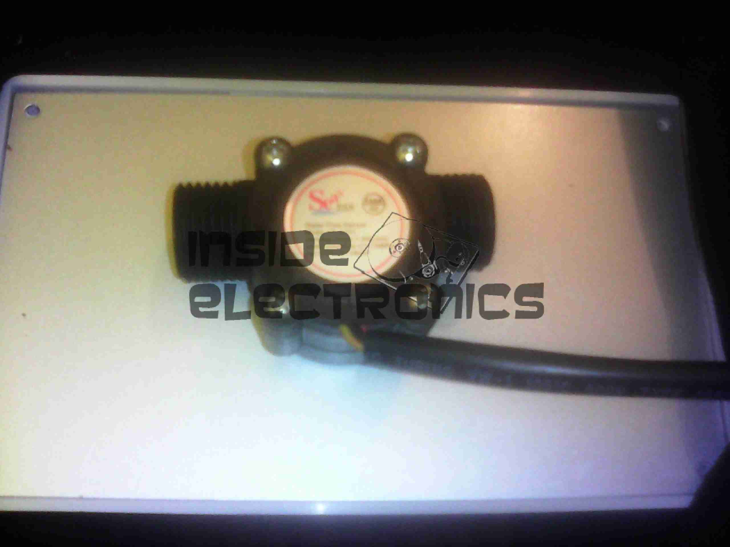
The sensor itself is a SP-15A Tin Oxide semiconductor type, most sensitive to butane & propane. Unlike the Chinese El-Cheapo versions on eBay, these are high quality sensors. After whiffing some gas from a lighter at one of the sensors, the alarm triggered instantly & tripped the solenoid off.

Solenoid Valve
Solenoid Valve

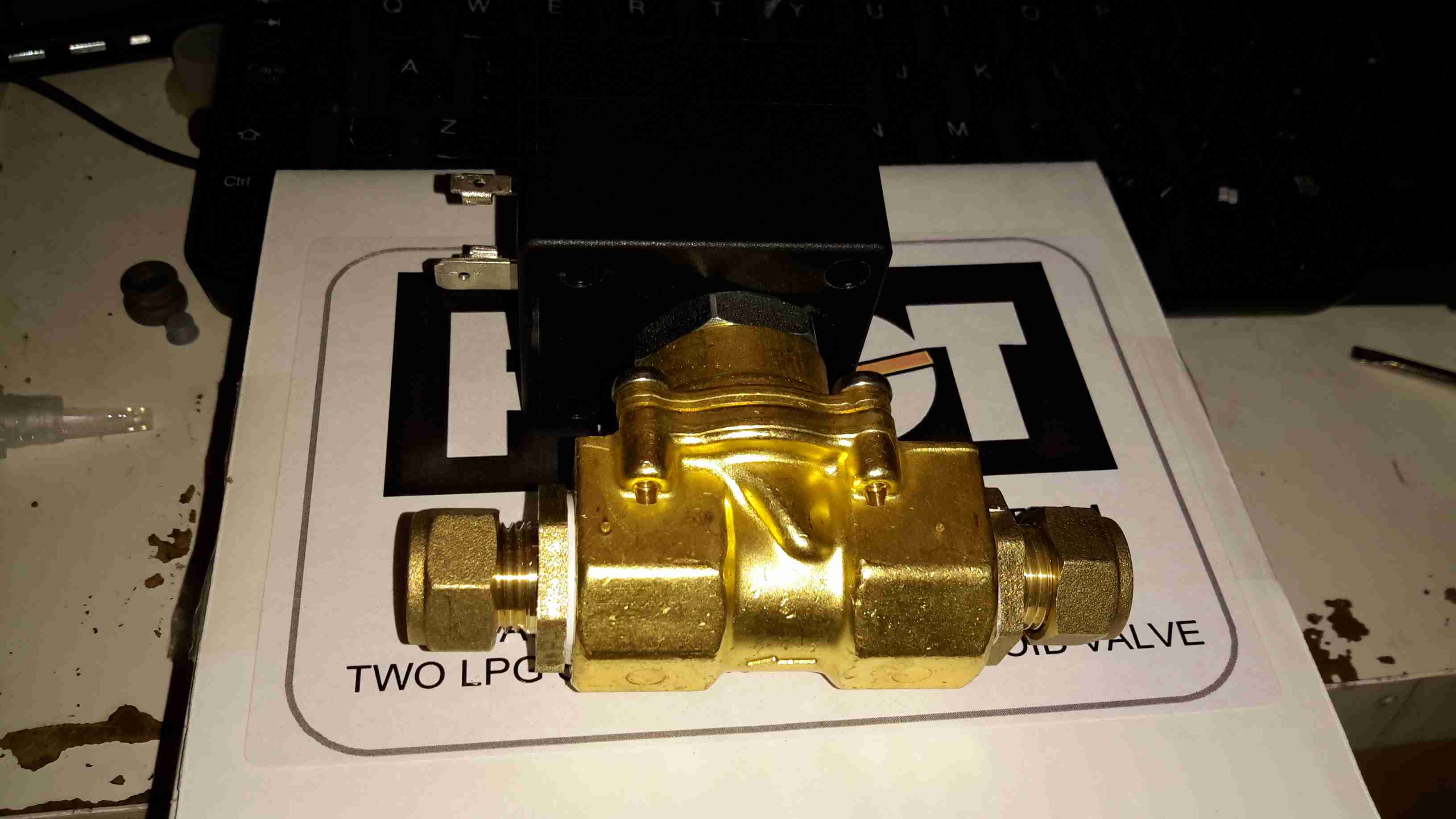
The solenoid valve goes into the gas supply line after the bottle regulator, in this case I’ve already fitted the adaptors to take the 10mm gas line to the 1/2″ BSP threads on the valve itself. This brass lump is a bit heavy, so support will be needed to prevent vibration compromising the gas line.

Posted on 1 Comment

SainSmart Frequency Meter

Thanks to Lewis, M3HHY for lending me this one 🙂

Here’s a quick look at a Sainsmart frequency counter module. These are useful little gadgets, showing the locked frequency on a small LCD display.

It’s built around an ATMega328 microcontroller (µC), and an MB501L Prescaler IC. The circuit for this is very simple, and is easily traced out from the board.

Frequency Counter
Frequency Counter

Here’s the back of the board, with the µC on the left & the prescaler IC on the right. This uses a rather novel method for calibration, which is the trimmer capacitor next to the crystal. This trimmer varies the frequency of the µC’s oscillator, affecting the calibration.

Input protection is provided by a pair of 1N4148 diodes in inverse parallel. These will clamp the input to +/-1v.
The prescaler IC is set to 1/64 divide ratio. This means that for an input frequency of 433MHz, it will output a frequency of 6.765625MHz to the µC.

The software in the µC will then calculate the input frequency from this intermediate frequency. This is done because the ATMega controllers aren’t very cabable of measuring such high frequencies.

The calculated frequency is then displayed on the LCD. This is a standard HD44780 display module.

LCD
LCD

Power is provided by a 9v PP3 battery, which is then regulated down by a standard LM7805 linear regulator.

Readout
Readout

I’ve found it’s not very accurate at all at the lower frequencies, when I fed it 40MHz from a signal generator it displayed a frequency of around 74MHz. This is probably due to the prescaler & the software not being configured for such a low input. In the case for 40MHz input the scaled frequency would have been 625kHz.


Posted on Leave a comment

AD9850 VFO Board

Continuing from my previous post where I published an Eagle design layout for AD7C‘s Arduino powered VFO, here is a completed board.

I have made some alterations to the design since posting, which are reflected in the artwork download in that post, mainly due to Eagle having a slight psychotic episode making me ground one of the display control signals!

AD9850 VFO
AD9850 VFO

The amplifier section is unpopulated & bypassed as I was getting some bad distortion effects from that section, some more work is needed there.
The Arduino Pro Mini is situated under the display, and the 5v rail is provided by the LM7805 on the lower left corner.

Current draw at 12v input is 150mA, for a power of 1.8W total. About 1W of this is dissipated in the LM7805 regulator, so I have also done a layout with an LM2574 Switching Regulator.
The SMPS version should draw a lot let power, as less is being dissipated in the power supply, but this version is more complex.

DDS VFO-SMPS
DDS VFO-SMPS

Here the SMPS circuit can be seen on the left hand side of the board, completely replacing the linear regulator.
I have not yet built this design, so I don’t know what kind of effect this will have on the output signal, versus the linear regulator. I have a feeling that the switching frequency of the LM2574 (52kHz) might produce some interference on the output of the DDS module. However I have designed this section to the standards in the datasheet, so this should be minimal.

Nevertheless this version is included in the Downloads section at the bottom of this post.

The output coupled through a 100nF capacitor is very clean, as can be seen below, outputting a 1kHz signal. Oscilloscope scale is 0.5ms/div & 1V/div.

VFO Output
VFO Output (Mucky ‘Scope)
Scope Connected
Scope Connected


Thanks again to Rich over at AD7C for the very useful tool design!

Linked below is the Eagle design files for this project, along with my libraries used to create it.

[download id=”5571″]

[download id=”5573″]

[download id=”5575″]

Posted on Leave a comment

Marine Potable Water Management System

LCD Panel
LCD Panel

Having two separate water tanks on nb Tanya Louise, with individual pumps, meant that monitoring water levels in tanks & keeping them topped up without emptying & having to reprime pumps every time was a hassle.
To this end I have designed & built this device, to monitor water usage from the individual tanks & automatically switch over when the tank in use nears empty, alerting the user in the process so the empty tanks can be refilled.

Based around an ATMega328, the unit reads a pair of sensors, fitted into the suction line of each pump from the tanks. The calculated flow is displayed on the 20×4 LCD, & logged to EEPROM, in case of power failure.

Water Flow Sensor
Water Flow Sensor

When the tank in use reaches a preset number of litres flowed, (currently hardcoded, but user input will be implemented soon), the pump is disabled & the other tank pump is enabled. This is also indicated on the display by the arrow to the left of the flow register. Tank switching is alerted by the built in beeper.
It is also possible to manually select a tank to use, & disable automatic operation.
Resetting the individual tank registers is done by a pair of pushbuttons, the total flow register is non-resettable, unless a hard reset is performed to clear the onboard EEPROM.

Main PCB
Main PCB

View of the main PCB is above, with the central Arduino Pro Mini module hosting the backend code. 12-24v power input, sensor input & 5v sensor power output is on the connectors on the left, while the pair of pump outputs is on the bottom right, switched by a pair of IRFZ44N logic-level MOSFETS. Onboard 5v power for the logic is provided by the LM7805 top right.

Code & PCB design is still under development, but I will most likely post the design files & Arduino sketch once some more polishing has been done.

Posted on 1 Comment

AVR Optical Tachometer

Here is an AVR powered optical tachometer design, that I adapted from the schematic found here.

I made a couple of changes to the circuit & designed a PCB & power supply module to be built in. The original design specified a surface mount IR LED/Photodiode pair, however my adjustment includes a larger IR reflectance sensor built onto the edge of the board, along with a Molex connector & a switch to select an externally mounted sensor instead of the onboard one.

There is also an onboard LM7805 based power supply, designed with a PCB mount PP3 battery box.
The power supply can also be protected by a 350mA polyfuse if desired. If this part isn’t fitted, then a pair of solder bridge pads are provided within the footprint for the fuse to short out the pads.

For more information on the basic design, please see the original post with the link at the top of the page.

Schematic
Schematic

Here is an archive of the firmware & the Eagle CAD files for the PCB & schematic design.


Posted on 1 Comment

Velleman MK179

Completed Kit
Completed Kit

This is the Velleman MK179 Proximity Card Reader, which is supplied in kit form. In the image above you can see the completed kit, the read coil is etched onto the black PCB on the left. Bringing a recognised card close to the coil operates the relay on the main PCB for a programmable amount of time.

Main PCB
Main PCB

Closeup of the main PCB, 12v DC input at top right. Left IC is an LM358 dual Op-Amp, the IC on the right is a PIC12F629 with Velleman’s custom firmware.
Logic power is supplied to the ICs & the oscillator from the LM7805 regulator at the top of the PCB. The relay is a standard 15A SPDT 12v coil relay, with the switch contacts broken out onto the screw terminals on the left.

Schematic Diagram
Schematic Diagram

As it is not provided with the kit, unlike other Velleman kits, here is the schematic for this.


Posted on 1 Comment

MSR605 3-Track Magnetic Stripe Writer

MSR605
MSR605

This unit was bought from eBay to experiment with Magnetic Stripe cards, for little money. This unit is capable of reading & writing all 3 tracks, & both Hi-Co & Lo-Co card types.
Interfaced to a PC through USB, this has a built in PL2303 USB-Serial IC & requires 3A at 9v DC to operate.
The 3 Indicator LEDs on the top of the unit can be toggled by the included software for Power/OK/Fault condition signalling.

Unit Bottom
Unit Bottom

Bottom of the unit with the model labels.

Model Label
Model Label

Closeup of the model label & serial number.

PCB Bottom
PCB Bottom

Here the bottom cover has been removed, showing the main PCB. The pair of large ICs bottom center interface with the magnetic heads. The IC above them has had the markings sanded off.

USB-Serial Interface

Closeup of the Prolific PL-2303 USB-Serial converter IC.

PCB Top
PCB Top

Here the connections to the R/W heads are visible, current limiting resistors at the left for the write head, a pair of signal relays, a pair of optoisolators & a LM7805 linear voltage regulator.

LEDs
LEDs

Here is the trio of indicator LEDs on a small sub-board.

Frame Bottom
Frame Bottom

The PCB has been removed from the main frame here, the only component visible is the rotary encoder.

Rotary Encoder
Rotary Encoder

The rotary encoder has a rubber wheel fitted, which reads the speed of the card as it is being swiped for writing. This allows the control logic to write the data to the stripe at the correct rate for the speed of the card. This allows the unit to write cards from 5-50 inches per second speed.
The Write head is directly behind the rubber pressure roller.

Read/Write Heads
Read/Write Heads

Here you can see the R/W head assembly. The write head is on the right, read on the left. When a card is written to, it immediately gets read by the second head for verification.

The drivers for this unit are also available here: Magcard Writer Drivers

Posted on Leave a comment

Marmitek Gigavideo 30

Antenna
Antenna

Here is a Marmitek Gigavideo 30 2.4GHz wireless video transmitter, has a receiver paired which will be uploaded shortly. Here is a view of the antennae, the large flat one being the 2.4GHz directional, the whip antenna possibly performing IR relay functions for the remote control.

Bottom Label
Bottom Label

For all those interested, here’s the bottom label.

PCB Top
PCB Top

The top cover removed reveals the main PCB. Big metal can is the RF transmitter circuitry. was encapsulated circuitry below that looks like an FM modulator for the whip antenna. Big TO220 package on heatsink is a LM7805 5-Volt regulator for the transmitter module.

These units work fantastically well when the antennas are aligned properly, at a decent range, however, they do have a nasty habit of doubling as a very effective WiFi LAN jammer.

Posted on Leave a comment

Belkin F5U021 4-Port USB Hub

Top
Top

This is an old USB 1.1 hub that was recently retired from service on some servers. Top of the unit visible here.

Bottom Label
Bottom Label

Bottom label shows that this is a model F5U021 hub, a rather old unit.

PCB Front
PCB Front

PCB is here removed from the casing, Indicator LEDs along the bottom edge of the board, power supply is on the left. Connectors on the top edge are external power, USB host, & the 4 USB outputs. Yellow devices are polyswitch fuses for the 500mA at 5v each port must supply.

USB Hub IC
USB Hub IC

This is the USB Hub Controller IC, which is a Texas Instruments TUSB2046B device. Power filter capacitors next to the USB ports are visible here also, along with 2 of the polyswitches.

Power Supply
Power Supply

The power supply section of the unit, which supplies regulated 5v to the ports, while supplying regulated 3.3v to the hub controller IC. Large TO-220 IC is the 5v regulator. Smaller IC just under the power selector switch is the 3.3v regulator for the hub IC. The switch selects between Host powered or external power for the hub.