Posted on 1 Comment

12v Temperature Controlled Soldering Iron

In my shack, 99% of my gear is all 12v powered, which is good for a few reasons:

  • Single Power Supply – This increases efficiency, as I’m only getting the losses of a single supply.
  • Safety – Mains voltages are dangerous, I’m not fond of working on such equipment.
  • Portability – I can power everything pretty much no matter were I am from a convenient car battery.
  • Convenience – Since everything is single supply, with all the same plugs, I don’t have to think about what goes where. This is more important due to my forgetfulness ;).

The one piece of equipment I regularly use that isn’t 12v is my soldering station. This is a Maplin A55KJ digital unit, which uses a 24v heating element.
While the soldering wand works OK when hooked direct to a 12v power supply (only at half power though), this removes the convenience of having temperature control.

The circuitry inside the unit is PIC microcontroller based, and doesn’t even bother rectifying the AC from the supply transformer before it’s sent to the heater. Because of this there are several reasons why I can’t just hook a DC-DC converter up to it to give it 24v.

It’s sensing the zero-crossing for the triac switch, to reduce heat dissipation, so it refuses to work at all with DC.

On looking at the Great Google, I found a project on Dangerous Prototypes, an Arduino based PID controller for soldering irons.

This requires that the soldering wand itself contains a thermocouple sensor – as the Maplin one I have is a cheap copy of the Atten 938D, it doesn’t actually use a thermocouple for temperature sensing. It appears to read the resistance of the element itself – Nichrome heating elements change resistance significantly depending on temperature.

I’ve managed to find a source of cheap irons on eBay, with built in thermocouples, so I’ve got a couple on order to do some testing with. While I wait for those to arrive, I’ve prototyped up the circuit on breadboard for testing:

Prototype
Prototype

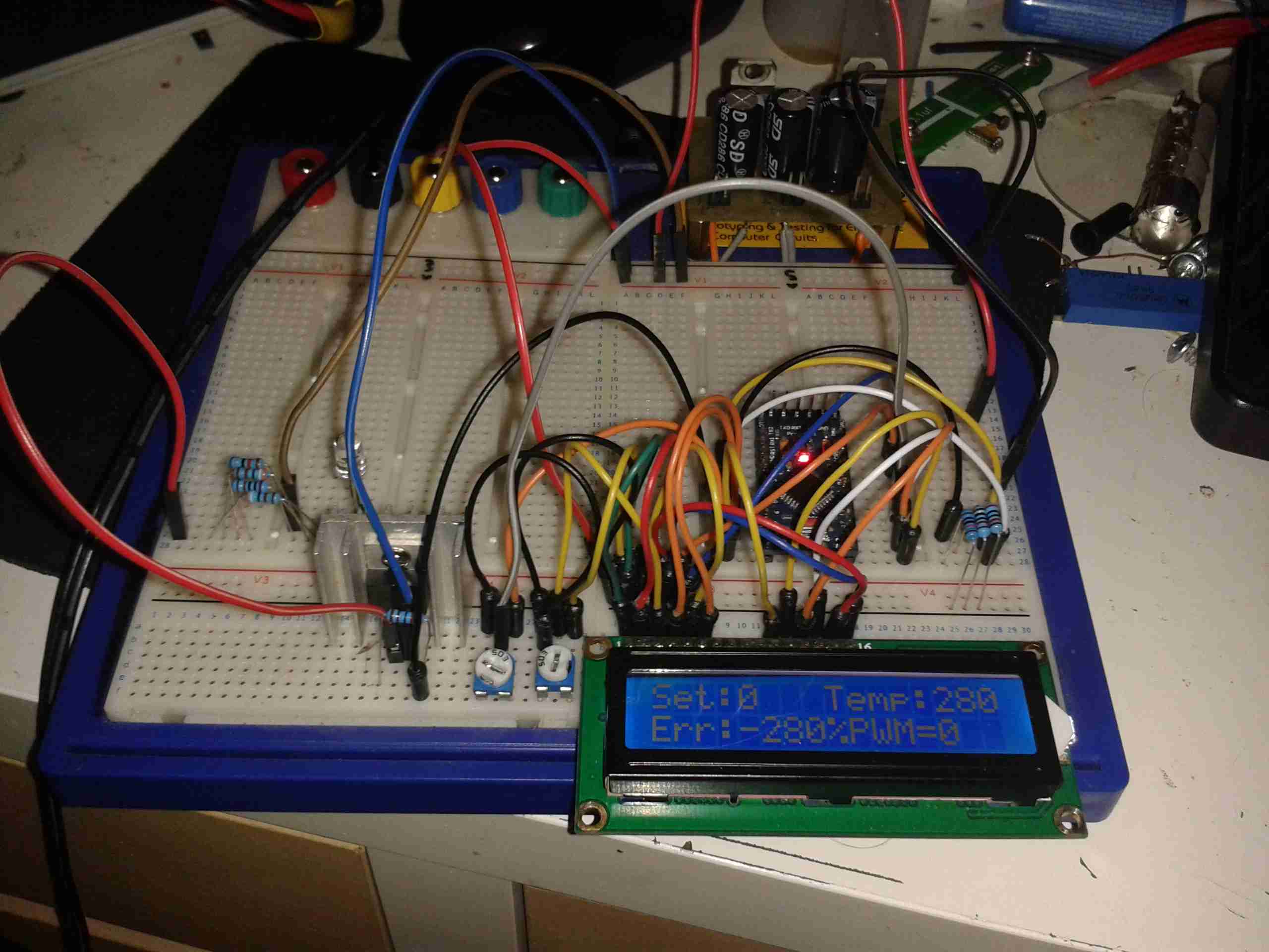
I’ve remapped some of the Arduino pins, to make PCB layout less of a headache, but the system is working OK so far, with manual input for the sensed temperature.
I’m using an IRL520N logic-level HEXFET for the power switching, rated at 10A. As the irons only draw a max of 4.5A, this is plenty beefy enough.
To come up with the +24v supply for the heater, a small DC-DC converter will be used.

More to come when the components for the thermocouple amplifier arrive, and the soldering irons themselves!

Posted on 3 Comments

Arduino Based SWR/PWR Meter – The Board

I recently posted about a small analog SWR/Power meter I got from eBay, and figured it needed some improvement.

After some web searching I located a project by ON7EQ, an Arduino sketch to read SWR & RF power from any SWR bridge.
The Arduino code is on the original author’s page above, his copyright restrictions forbid me to reproduce it here.

I have also noticed a small glitch in the code when it is flashed to a blank arduino: The display will show scrambled characters as if it has crashed. However pushing the buttons a few times & rebooting the Arduino seems to fix this. I think it’s related to the EEPROM being blank on a new Arduino board.

I have run a board up in Eagle for testing, shown below is the layout:

SWR Meter SCH
SWR Meter SCH

The Schematic is the same as is given on ON7EQ’s site.
Update: ON7EQ has kindly let me know I’ve mixed up R6 & R7, so make sure they’re switched round when the board is built ;). Fitting the resistors the wrong way around may damage the µC with overvoltage.

SWR Meter PCB
SWR Meter PCB

Here’s the PCB layout. I’ve kept it as simple as possible with only a single link on the top side of the board.

PCB Top
PCB Top

Here’s the freshly completed PCB ready to rock. Arduino Pro mini sits in the center doing all the work.
The link over to A5 on the arduino can be seen here, this allows the code to detect the supply voltage, useful for battery operation.
On the right hand edge of the PCB are the pair of SMA connectors to interface with the SWR bridge. Some RF filtering is provided on the inputs.

PCB Bottom
PCB Bottom

Trackside view of the PCB. This was etched using my tweaked toner transfer method.

LCD Fitted
LCD Fitted

Here the board has it’s 16×2 LCD module.

Online
Online

Board powered & working. Here it’s set to the 70cm band. The pair of buttons on the bottom edge of the board change bands & operating modes.
As usual, the Eagle layout files are available below, along with the libraries I use.

[download id=”5585″]

[download id=”5573″]

More to come on this when some components arrive to interface this board with the SWR bridge in the eBay meter.

Posted on 4 Comments

AD9850 DDS VFO PCB & Schematic Layout

I recently came across a design for an Arduino controlled AD9850 DDS module, created by AD7C, so I figured I would release my Eagle CAD design for the PCB here.

It is a mainly single-sided layout, only a few links on the top side are needed so this is easy to etch with the toner transfer method.

My version uses an Arduino Pro Mini, as the modular format is much easier to work with than a bare ATMega 328.

RF output is via a SMA connector & has a built in amplifier to compensate for the low level generated by the DDS Module.

DDS VFO
DDS VFO

Version 2 Update: Added reverse polarity protection, added power indicator LED, beefed up tracks around the DC Jack.
[download id=”5571″]

Posted on Leave a comment

Marine Potable Water Management System

LCD Panel
LCD Panel

Having two separate water tanks on nb Tanya Louise, with individual pumps, meant that monitoring water levels in tanks & keeping them topped up without emptying & having to reprime pumps every time was a hassle.
To this end I have designed & built this device, to monitor water usage from the individual tanks & automatically switch over when the tank in use nears empty, alerting the user in the process so the empty tanks can be refilled.

Based around an ATMega328, the unit reads a pair of sensors, fitted into the suction line of each pump from the tanks. The calculated flow is displayed on the 20×4 LCD, & logged to EEPROM, in case of power failure.

Water Flow Sensor
Water Flow Sensor

When the tank in use reaches a preset number of litres flowed, (currently hardcoded, but user input will be implemented soon), the pump is disabled & the other tank pump is enabled. This is also indicated on the display by the arrow to the left of the flow register. Tank switching is alerted by the built in beeper.
It is also possible to manually select a tank to use, & disable automatic operation.
Resetting the individual tank registers is done by a pair of pushbuttons, the total flow register is non-resettable, unless a hard reset is performed to clear the onboard EEPROM.

Main PCB
Main PCB

View of the main PCB is above, with the central Arduino Pro Mini module hosting the backend code. 12-24v power input, sensor input & 5v sensor power output is on the connectors on the left, while the pair of pump outputs is on the bottom right, switched by a pair of IRFZ44N logic-level MOSFETS. Onboard 5v power for the logic is provided by the LM7805 top right.

Code & PCB design is still under development, but I will most likely post the design files & Arduino sketch once some more polishing has been done.