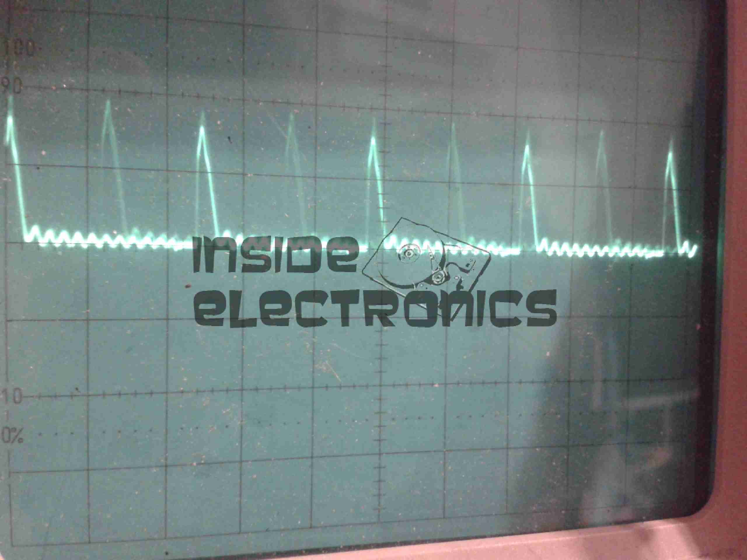
Since I fitted my scope with a SMPS based 12v input supply, there has been a noise problem on very low volts/div settings, this noise isn’t present on the mains supply, so I can only think it’s coming from the switching frequencies of the various DC-DC modules I’ve used.
Scope Ripple
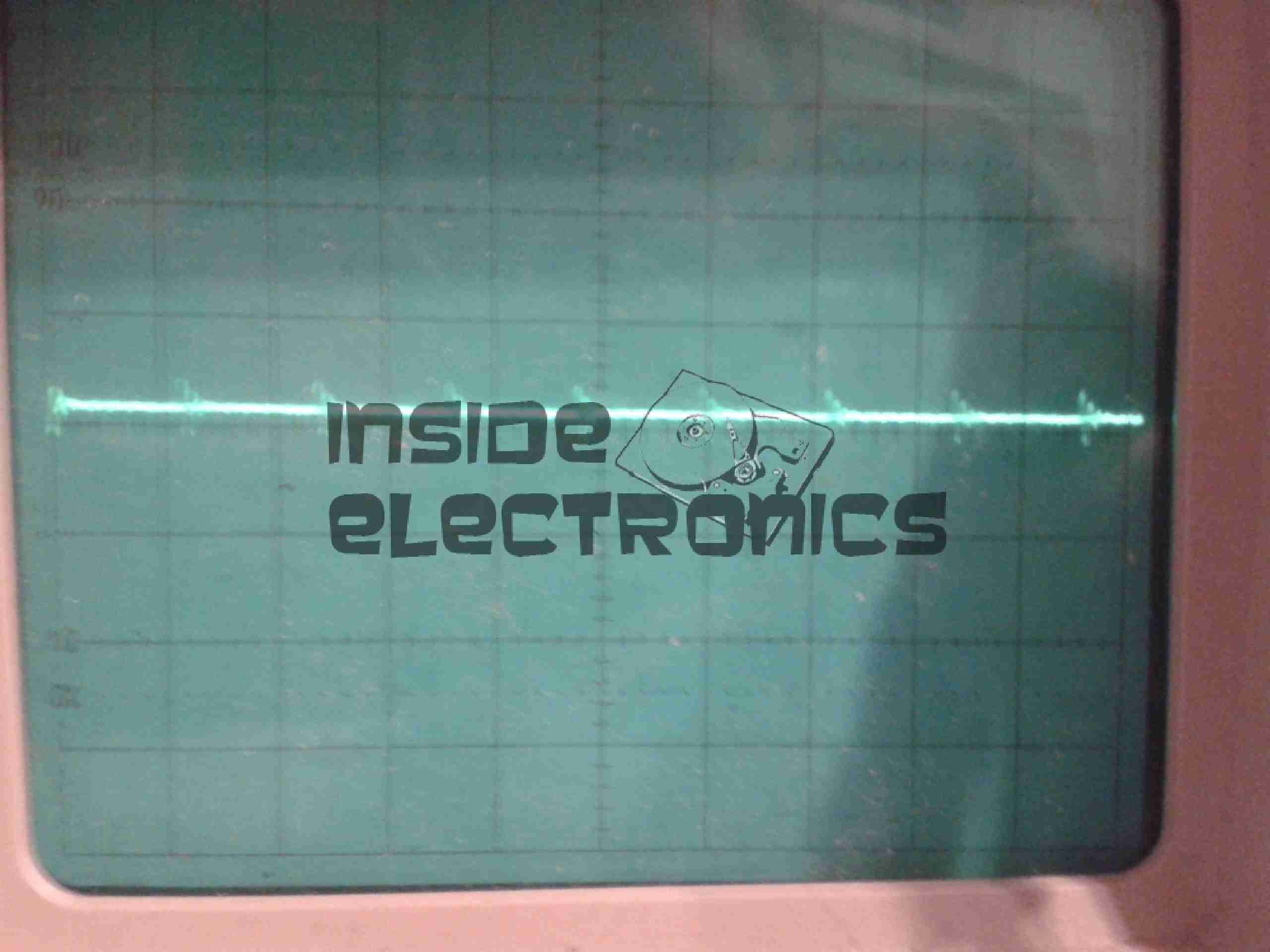
Because of this I’ve designed a linear post-regulation stage for the supply, to remove the RFI from the DC rails.
This board takes the outputs from the DC-DC converters, removes all the noise & outputs clean DC onto the mainboard of the scope.
As the scope internally uses regulation to get the voltages lower, I’ve found that I don’t have to match the outputs of the mains supply exactly, for the +/-17.5v rails, 12v is perfectly fine instead.
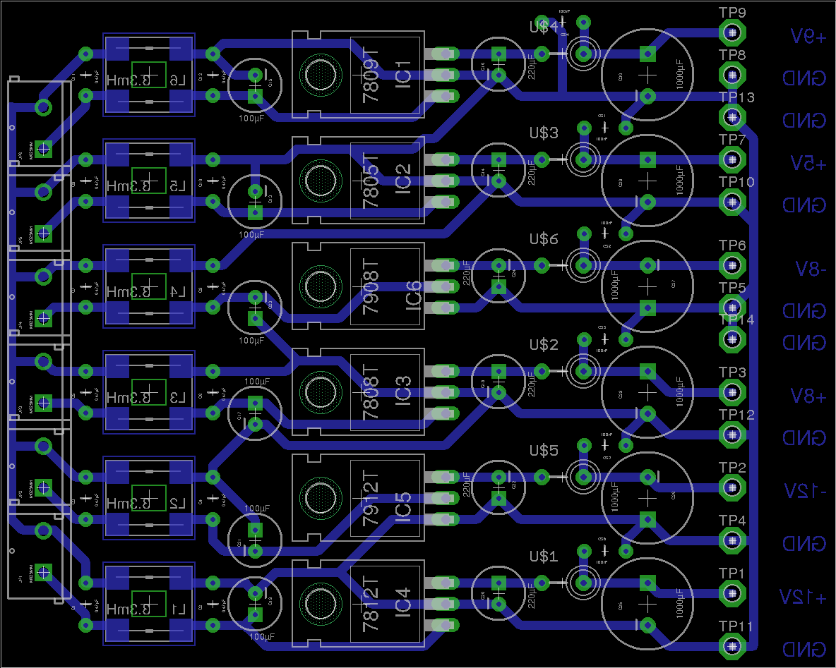
Scope Linear PSU
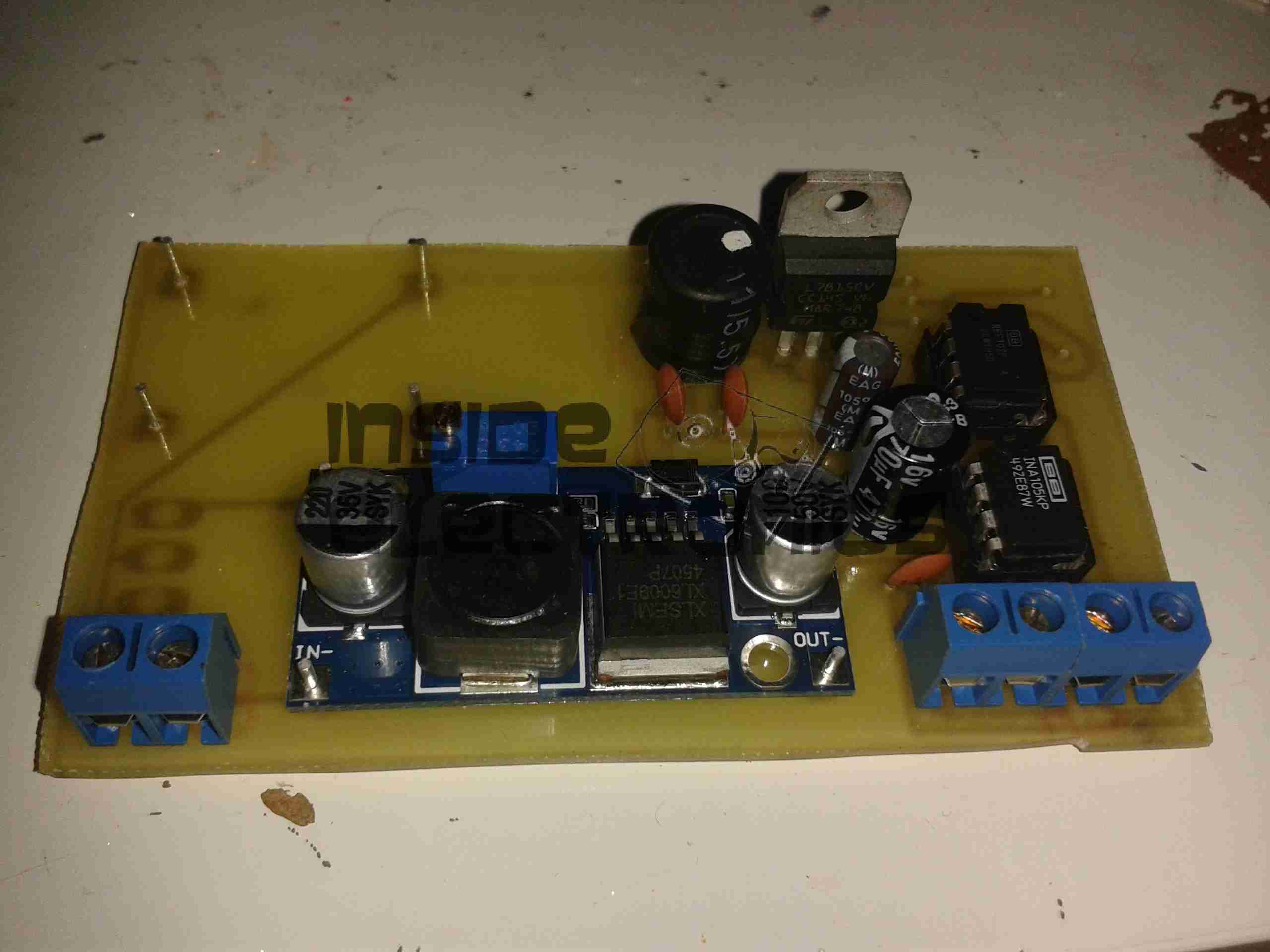
Here’s the PCB layout, with the 6 common mode filters on the input (left), linear regulator ICs in the centre & the output filters on the right.
Scope Linear PSU
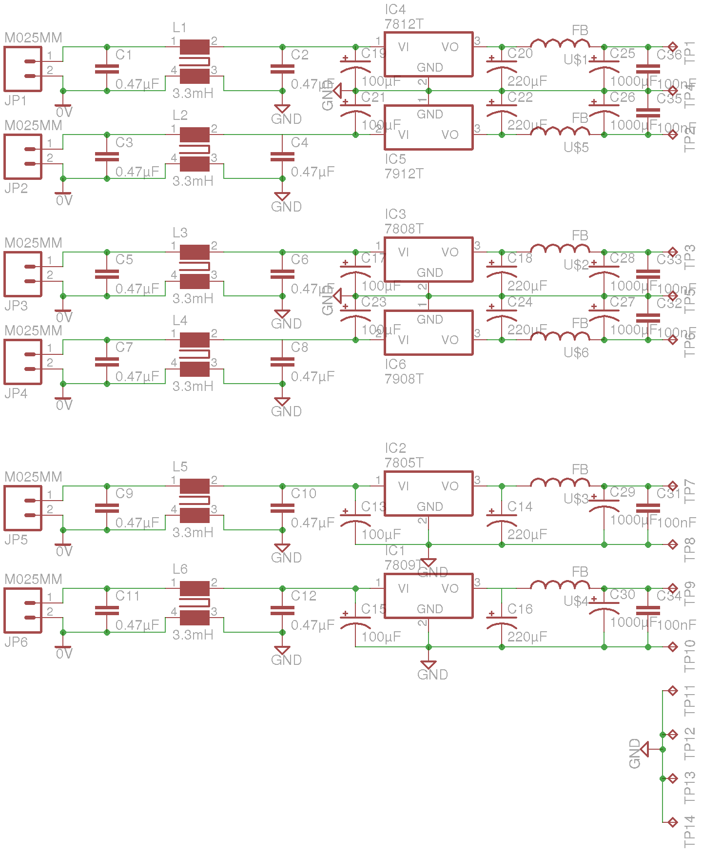
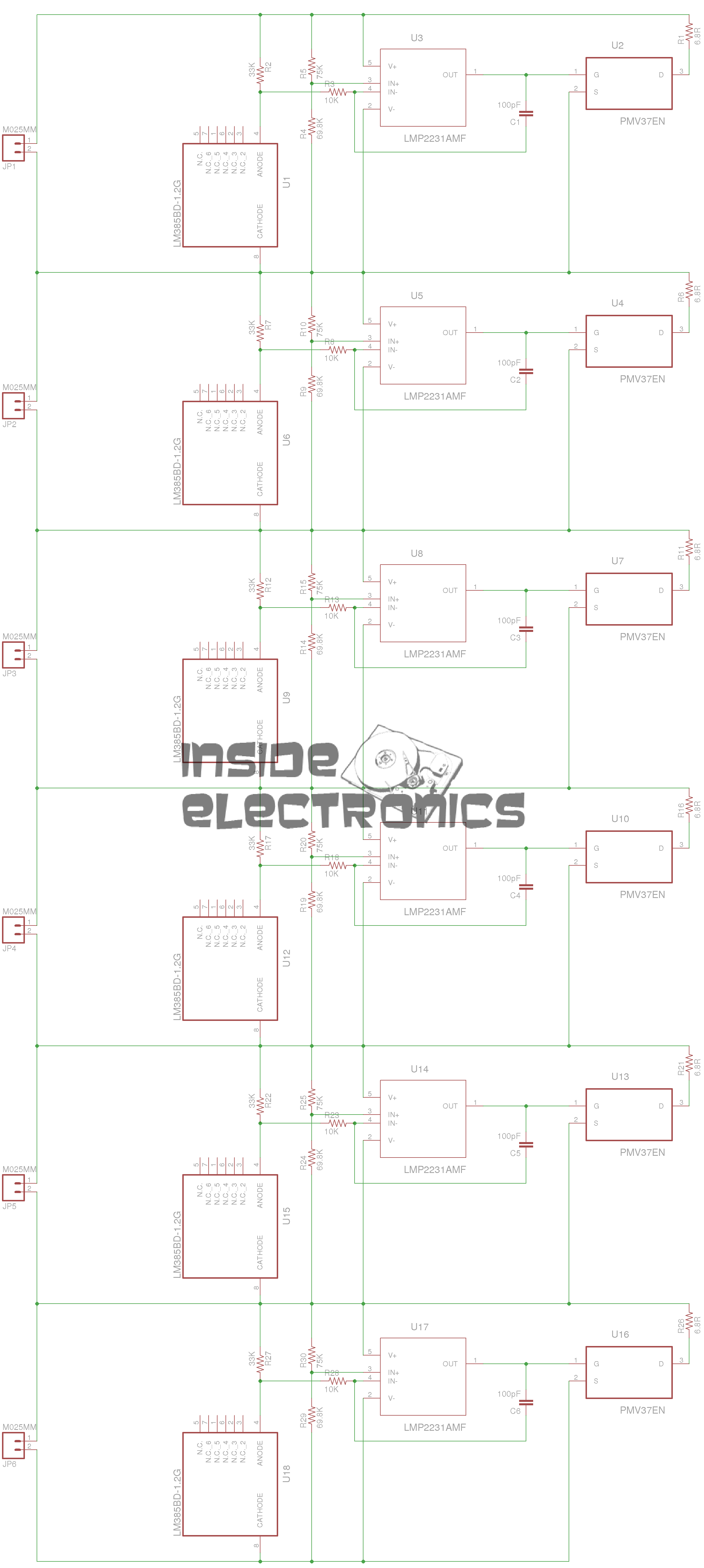
Here’s the schematic layout, as usual the Eagle Project files are in the link below, I’ll update when I have built the board & tested!
In my shack, 99% of my gear is all 12v powered, which is good for a few reasons:
Single Power Supply – This increases efficiency, as I’m only getting the losses of a single supply.
Safety – Mains voltages are dangerous, I’m not fond of working on such equipment.
Portability – I can power everything pretty much no matter were I am from a convenient car battery.
Convenience – Since everything is single supply, with all the same plugs, I don’t have to think about what goes where. This is more important due to my forgetfulness ;).
The one piece of equipment I regularly use that isn’t 12v is my soldering station. This is a Maplin A55KJ digital unit, which uses a 24v heating element.
While the soldering wand works OK when hooked direct to a 12v power supply (only at half power though), this removes the convenience of having temperature control.
The circuitry inside the unit is PIC microcontroller based, and doesn’t even bother rectifying the AC from the supply transformer before it’s sent to the heater. Because of this there are several reasons why I can’t just hook a DC-DC converter up to it to give it 24v.
It’s sensing the zero-crossing for the triac switch, to reduce heat dissipation, so it refuses to work at all with DC.
On looking at the Great Google, I found a project on Dangerous Prototypes, an Arduino based PID controller for soldering irons.
This requires that the soldering wand itself contains a thermocouple sensor – as the Maplin one I have is a cheap copy of the Atten 938D, it doesn’t actually use a thermocouple for temperature sensing. It appears to read the resistance of the element itself – Nichrome heating elements change resistance significantly depending on temperature.
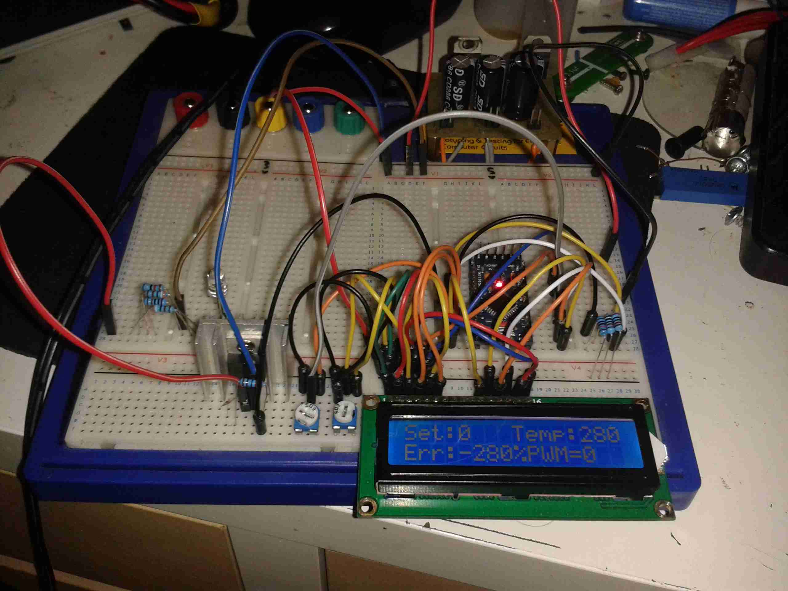
I’ve managed to find a source of cheap irons on eBay, with built in thermocouples, so I’ve got a couple on order to do some testing with. While I wait for those to arrive, I’ve prototyped up the circuit on breadboard for testing:
Prototype
I’ve remapped some of the Arduino pins, to make PCB layout less of a headache, but the system is working OK so far, with manual input for the sensed temperature.
I’m using an IRL520N logic-level HEXFET for the power switching, rated at 10A. As the irons only draw a max of 4.5A, this is plenty beefy enough.
To come up with the +24v supply for the heater, a small DC-DC converter will be used.
More to come when the components for the thermocouple amplifier arrive, and the soldering irons themselves!
I recently posted about a small analog SWR/Power meter I got from eBay, and figured it needed some improvement.
After some web searching I located a project by ON7EQ, an Arduino sketch to read SWR & RF power from any SWR bridge.
The Arduino code is on the original author’s page above, his copyright restrictions forbid me to reproduce it here.
I have also noticed a small glitch in the code when it is flashed to a blank arduino: The display will show scrambled characters as if it has crashed. However pushing the buttons a few times & rebooting the Arduino seems to fix this. I think it’s related to the EEPROM being blank on a new Arduino board.
I have run a board up in Eagle for testing, shown below is the layout:
SWR Meter SCH
The Schematic is the same as is given on ON7EQ’s site. Update: ON7EQ has kindly let me know I’ve mixed up R6 & R7, so make sure they’re switched round when the board is built ;). Fitting the resistors the wrong way around may damage the µC with overvoltage.
SWR Meter PCB
Here’s the PCB layout. I’ve kept it as simple as possible with only a single link on the top side of the board.
PCB Top
Here’s the freshly completed PCB ready to rock. Arduino Pro mini sits in the center doing all the work.
The link over to A5 on the arduino can be seen here, this allows the code to detect the supply voltage, useful for battery operation.
On the right hand edge of the PCB are the pair of SMA connectors to interface with the SWR bridge. Some RF filtering is provided on the inputs.
PCB Bottom
Trackside view of the PCB. This was etched using my tweaked toner transfer method.
LCD Fitted
Here the board has it’s 16×2 LCD module.
Online
Board powered & working. Here it’s set to the 70cm band. The pair of buttons on the bottom edge of the board change bands & operating modes.
As usual, the Eagle layout files are available below, along with the libraries I use.
[download id=”5585″]
[download id=”5573″]
More to come on this when some components arrive to interface this board with the SWR bridge in the eBay meter.
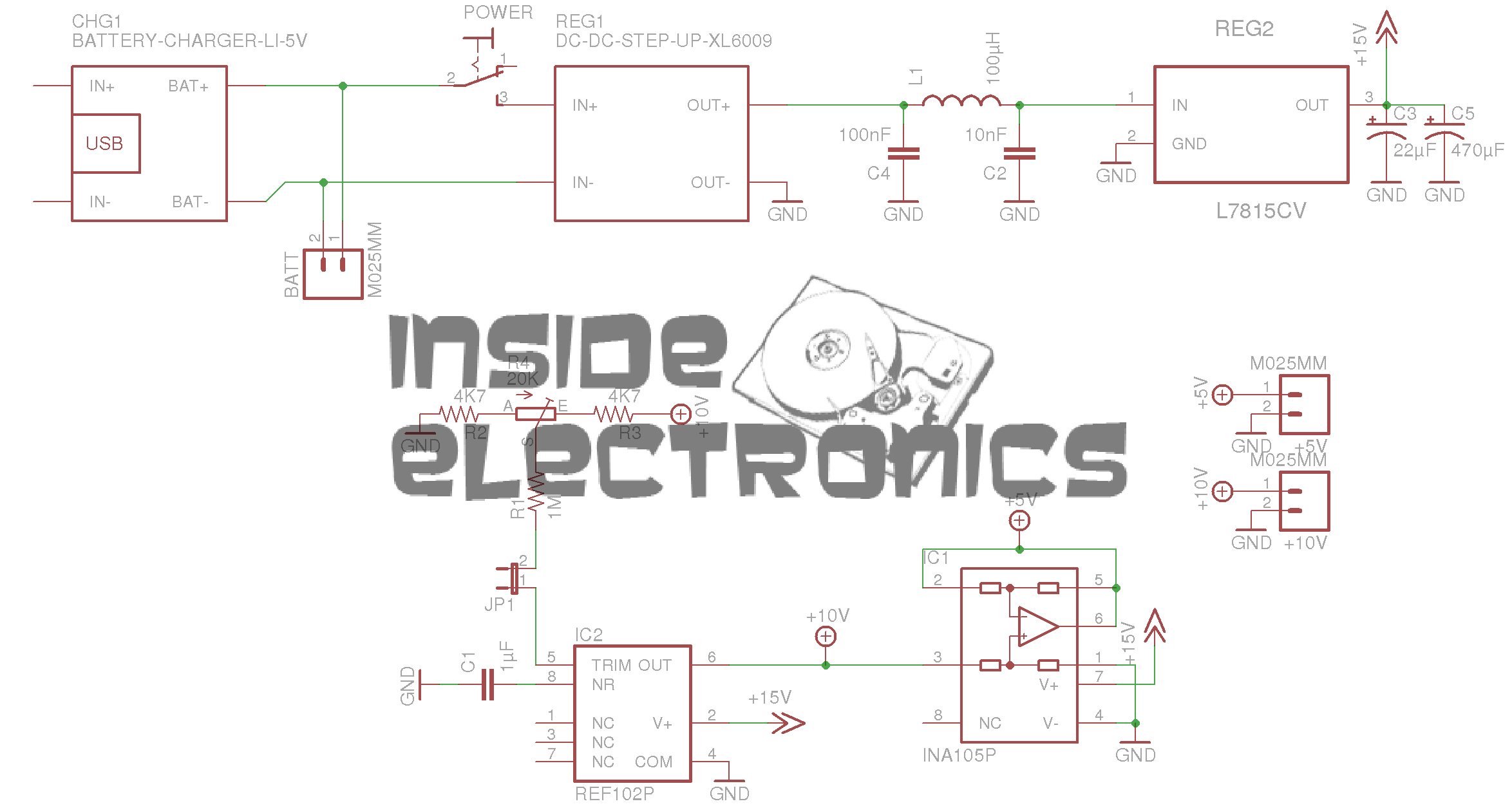
After watching a video over at Scullcom Hobby Electronics on YouTube, I figured I’d build one of these precision references to calibrate my multimeters.
It’s based around a REF102P 10v precision reference & an INA105P precision unity gain differential amplifier.
For full information, check out the video, I won’t go into the details here, just my particular circuit & PCB layout.
In the video, Veroboard is used. I’m not too fond of the stuff personally. I find it far too easy to make mistakes & it never quite looks good enough. To this end I have spun a board in Eagle, as usual.
Precision Ref SCH – Click to Embiggen
Here’s the schematic layout, the same as is in the video.
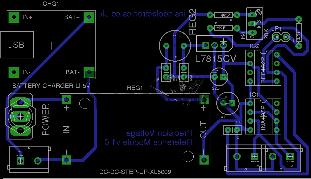
Precision Ref BRD
As usual, the Eagle CAD layout files can be found at the bottom of the post.
And the associated PCB layout. I have added the option to be able to tweak the output, to get a more accurate calibration, which can be added by connecting JP1 on the PCB.
As in the original build, this unit uses pre-built DC-DC converter & Li-Ion charger modules. A handy Eagle library can be found online for these parts.
I have however left off the battery monitor section of the circuit, since I plan to use a protected lithium cell for power. This also allowed me to keep the board size down, & use a single sided layout.
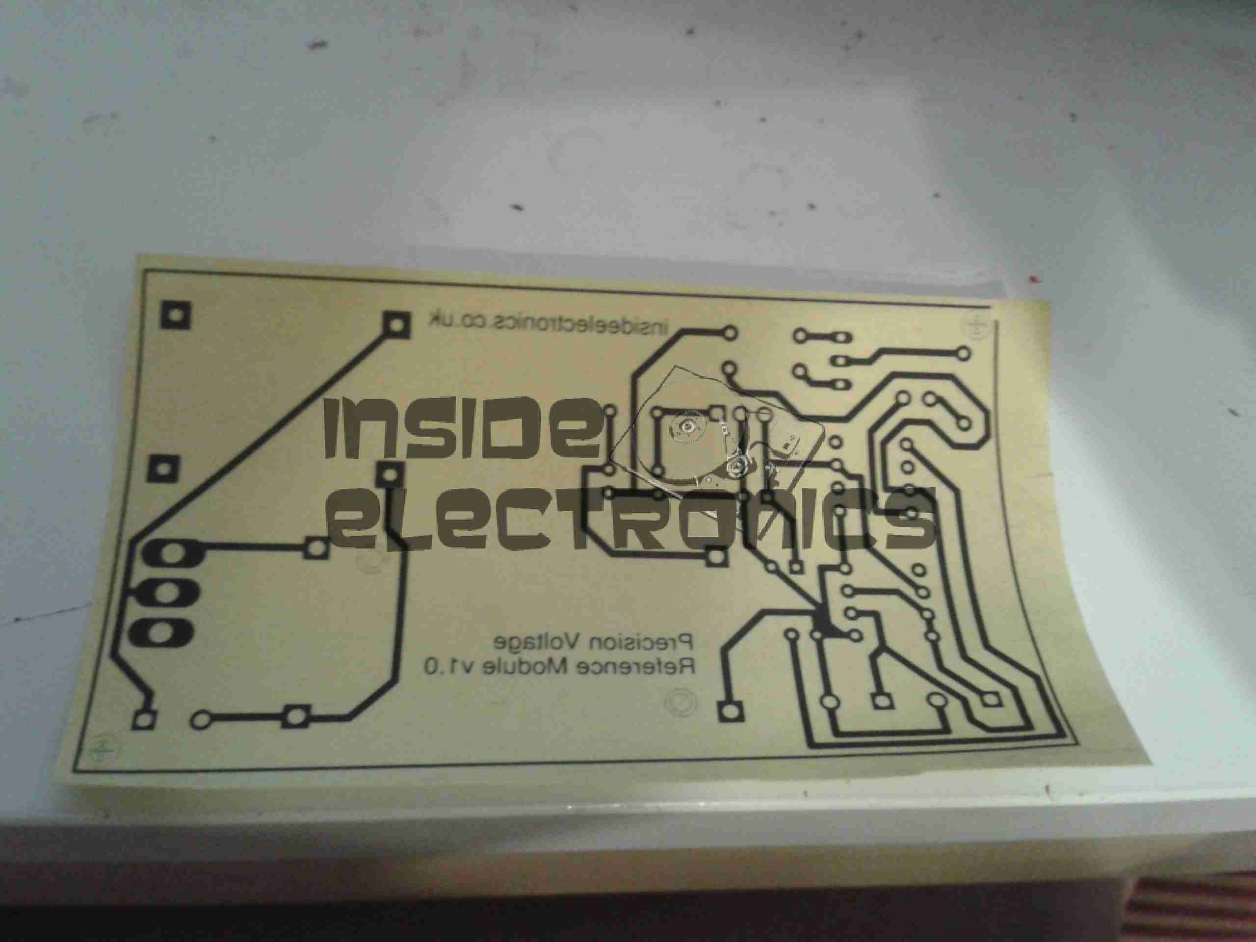
Toner Transfer Paper
Here’s the track layout ready to iron onto the copper clad board. I use the popular toner transfer system with special paper from eBay, this stuff has a coating that allows the toner to easily be transferred to the PCB without having to mess about with soaking in water & scraping paper off.
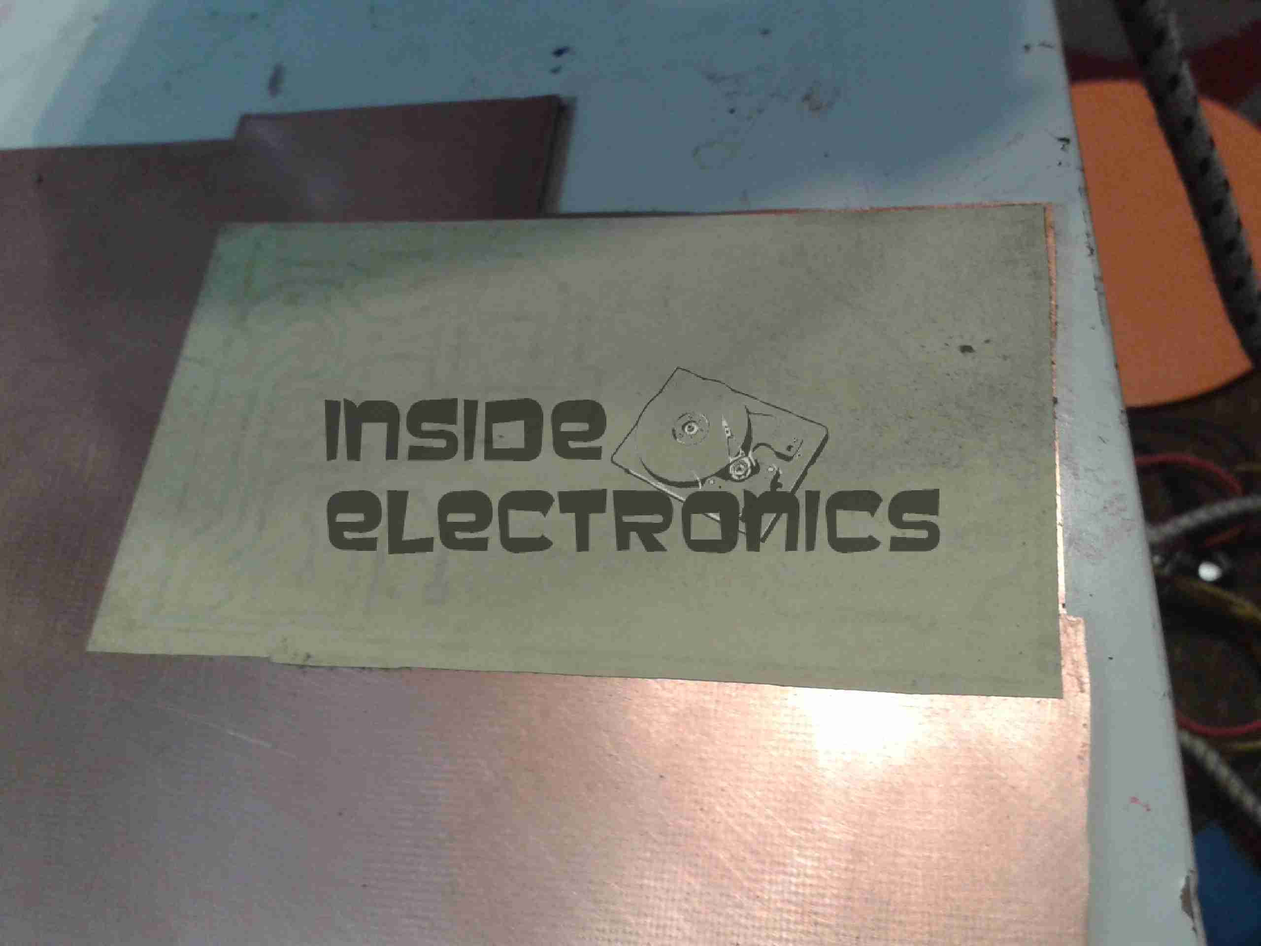
Ironed On
Here’s the paper having just been ironed onto the copper. After waiting for the board to cool off the paper is peeled off, leaving just the toner on the PCB.
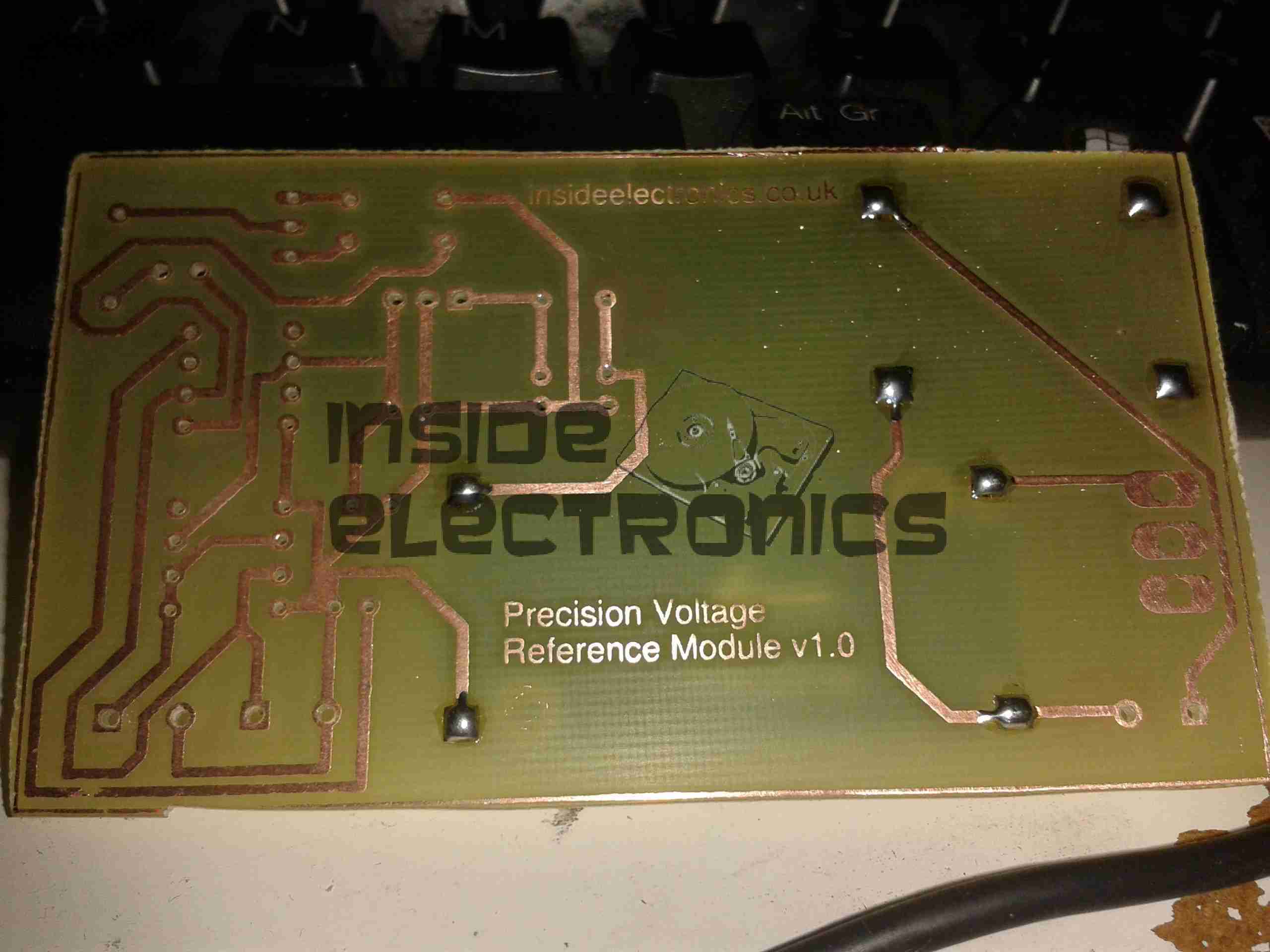
Etched PCB
PCB just out of the etch tank, drilled & with the solder pins for the modules installed. Only one issue with the transfer, in the bottom left corner of the board is visible, a very small section of copper was over etched.
This is easily fixed with a small piece of wire.
Components Populated
Main components populated. The DC-DC converter is set at 24v output, which the linear regulator then drops down to the +15v rail for the reference IC. The linear section of the regulator, along with the LC filter on the output of the switching regulator produce a low-ripple supply.
SMPS Ripple
Here’s the scope reading the AC ripple on the output of the DC-DC converter. Scale is 100mV/Div. Roughly 150mV of ripple is riding on top of the DC rail.
Linear PSU Ripple
And here’s the output from the linear regulator, scale of 50mV/Div. Ripple has been reduced to ~15mV for the reference IC.
In total the circuit as built has a power consumption of ~0.5W, most of which is being dissipated as heat in the linear part of the PSU.
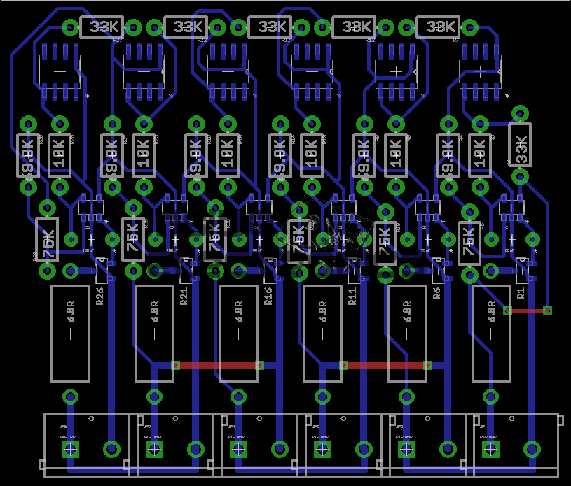
Here’s another active balancing circuit for large ultracapacitor banks, this one is designed for a series string of 6, at 2.5v per capacitor.
Based on the design here, I have transcribed the circuit into Eagle & designed a PCB layout.
Ultracap Balancer Circuit – Click to Embiggen
As can be seen from the circuit diagram above, this is just 6 copies of the circuit from the above link, with screw terminals to attach to the capacitor string.
Ultracap Balancer PCB
And here’s the PCB. the MOSFETs & OpAmps are very small SMT parts, so require a steady hand in soldering. This board can easily be etched by hand as there’s only 3 links on the top side. No need for a double sided PCB.
As always, the Eagle project files & my Eagle library collection are available below:
I’ve been doing some tinkering with the RN-52 Bluetooth Audio module from Roving Networks, in prep for building a portable wireless speaker system, & thought I’d share my designs.
Initially I was having some issues with RF noise on the audio output from the RN-52, as I was only using the outputs single-ended. The module didn’t like this treatment, with all the RF whine coming straight out of the speakers.
To fix this issue I have used a pair of jellybean LM386 audio power amplifiers, running in differential input mode. This solves the high-pitched whine when the audio is enabled, & also allows the module to directly drive a set of 32Ω headphones at a reasonable level.
In Eagle I have designed a simple board, routing only the audio output, serial TTL & command mode pins out, along with the supporting power supply circuitry to operate from 12v DC.
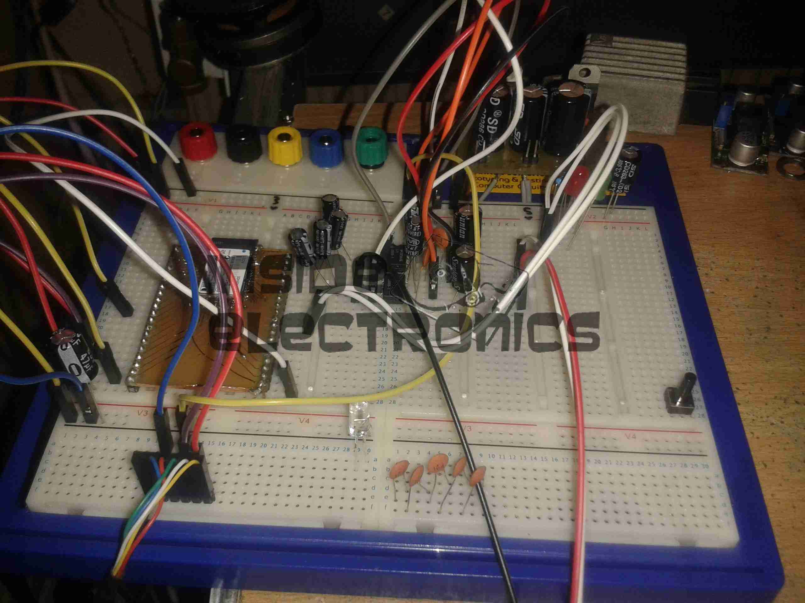
RN-52 Breadboard
Above is the current incarnation of the circuit on the breadboard. The RN-52 is on the left, audio power stage in the centre & headphone output on the right.
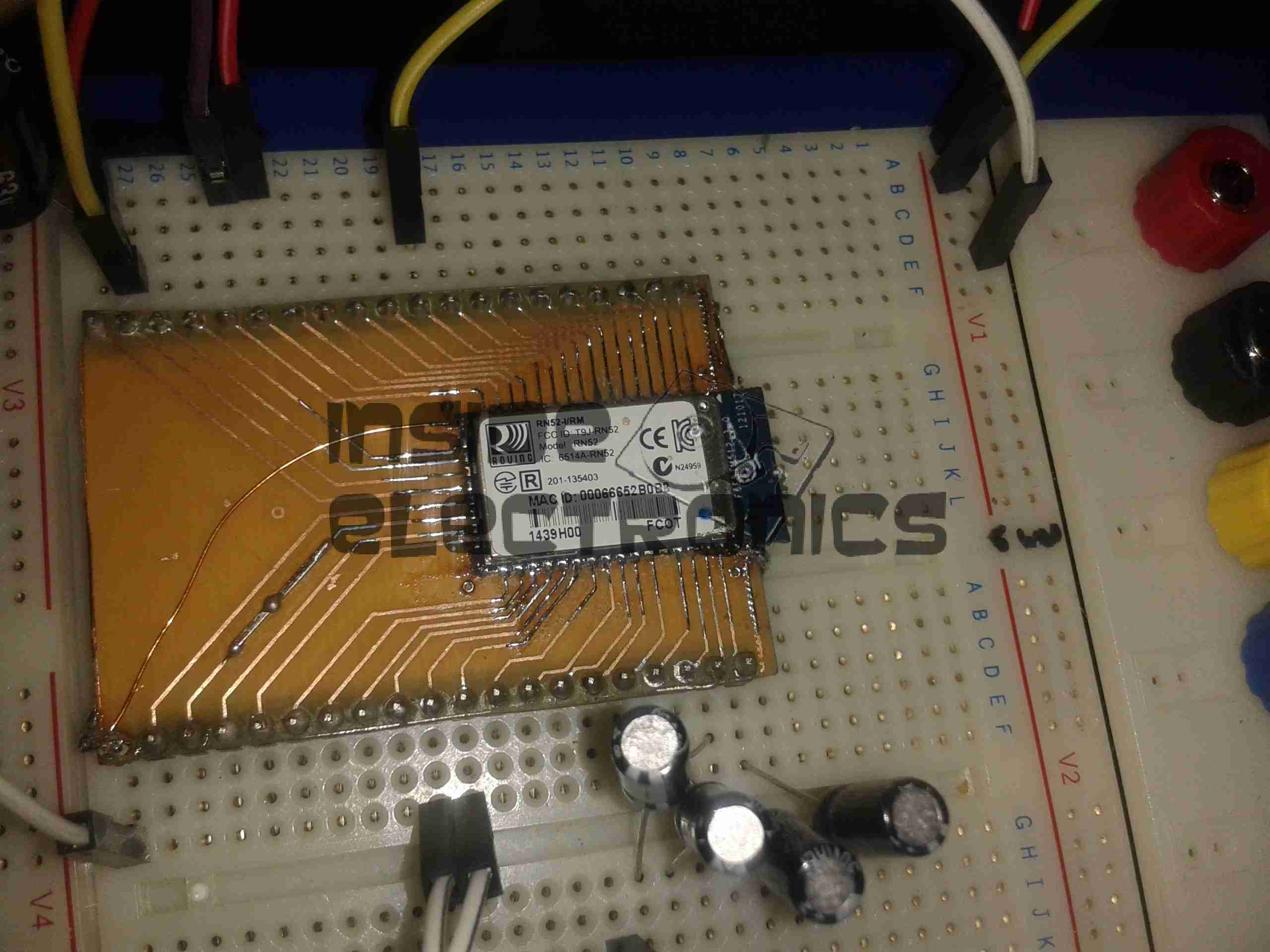
RN-52 Breakout
The bluetooth module on a breakout board. I was cheap in this case & etched my own board. I’m not paying Sparkfun, (as much as I like them), an extra ~£10 for a small PCB with the pins broken out. Much cheaper to spend 15 minutes with the laser printer & the iron, & do a toner transfer PCB.
As this board is single sided, I added a ground plane on the underside with copper foil, to help with the RF issues. Breadboards really aren’t all that good at rejecting noise induced when there’s a 2.4GHz transceiver mounted on them.
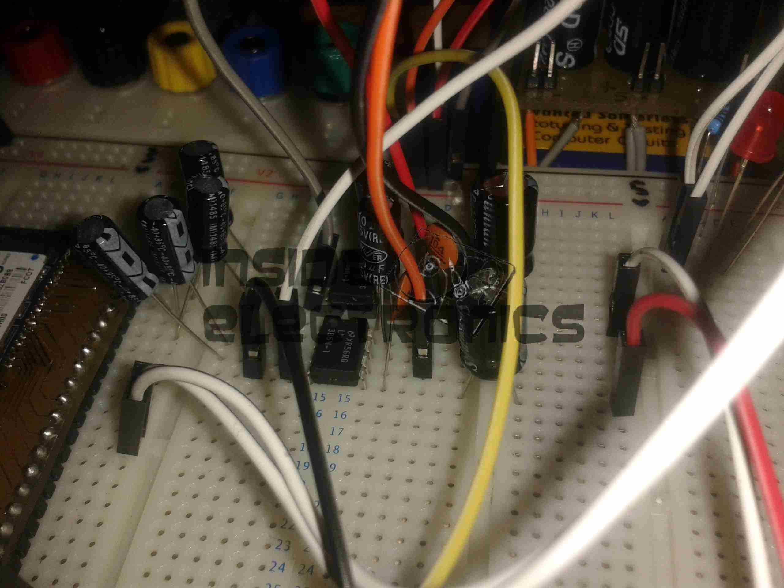
LM386 Amplifier
The LM386 audio power stage. The differential inputs from the module are capacitively coupled with 1µF electrolytics. This setup remarkably reduced the noise on the output. I left these at their default gain of 20, as I’ll be connecting another high power amplifier stage to drive large speakers.
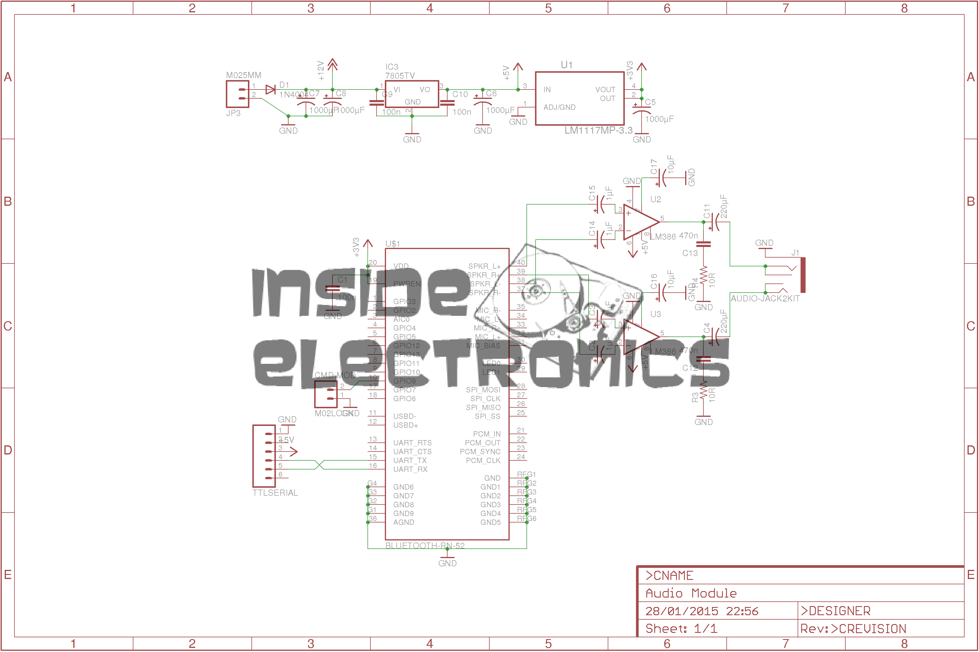
RN-52 Eagle Layout
Here’s the circuit laid out in Eagle, ready for PCB.
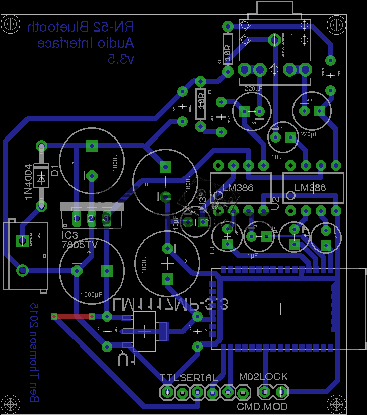
RN-52 Eagle PCB
And here’s the PCB layout. Only one link required for the +5v line from the TTL serial port.
As always, the Eagle PCB & Schematic layout files are available at the bottom of the article.
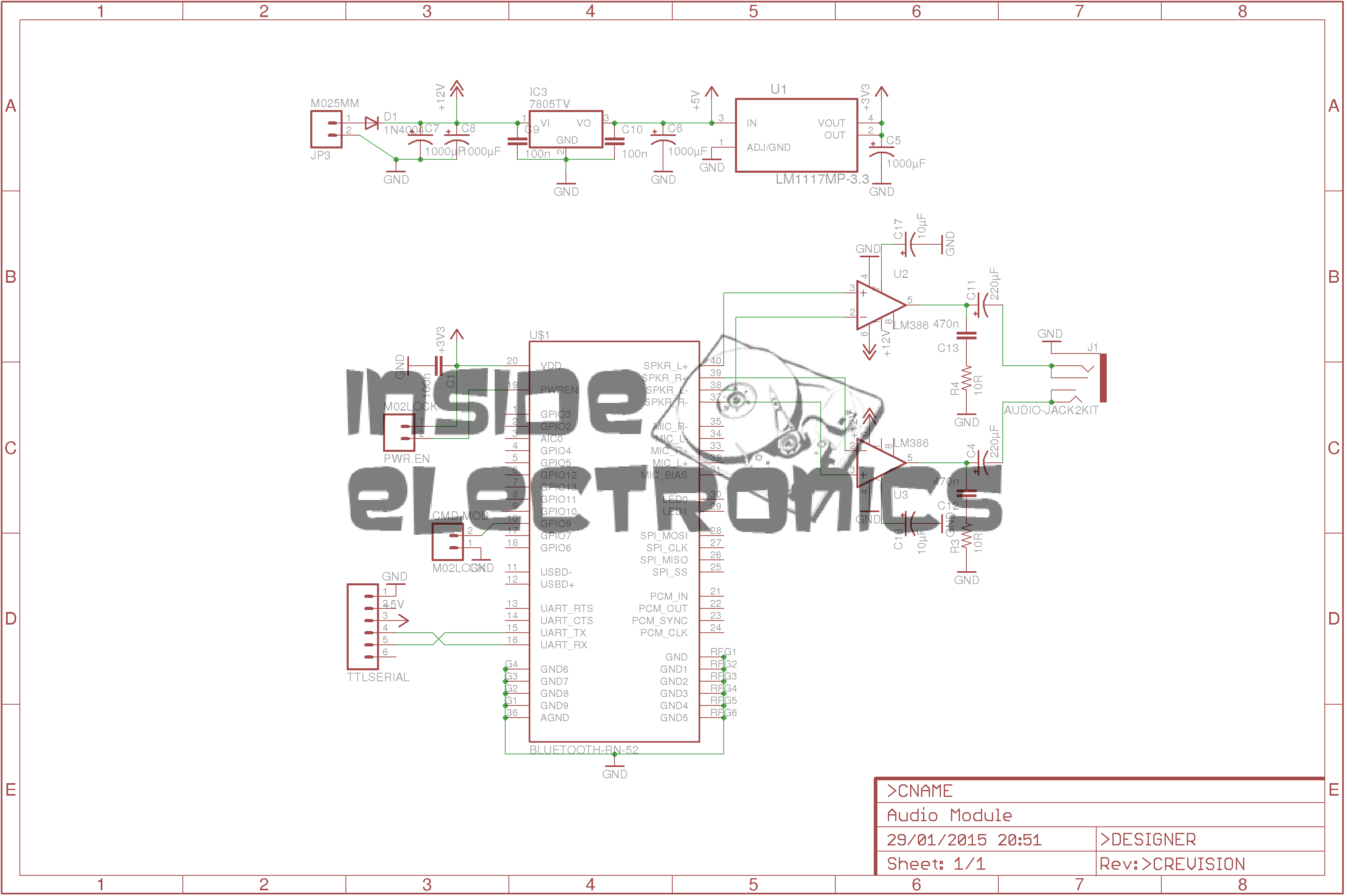
*Update 29-01-15*
Rerouted a few things:
Moved the audio power stage to the +12v rail to improve sound response. – As the LM386 has a max input voltage of 12v (absolute maximum 15v), a regulated supply is recommended. The LM386-N4 variant has a higher voltage range, up to 18v. This should be suitable for an unregulated supply.
Removed 1µF coupling capacitors to reduce distortion & amplifier hiss. The capacitors appeared to cause some instability on the amplifier, causing random distortion. Removing them has cured this. No signal hiss has also been reduced to a very low level.
Reversed input polarity on input of one of the amplifiers – this appears to produce better audio.
Added PWR.EN header to allow connection of power button. Saves hassle of cycling power to the board when the RN-52 goes into sleep mode.
Improved PCB & Schematic layouts.
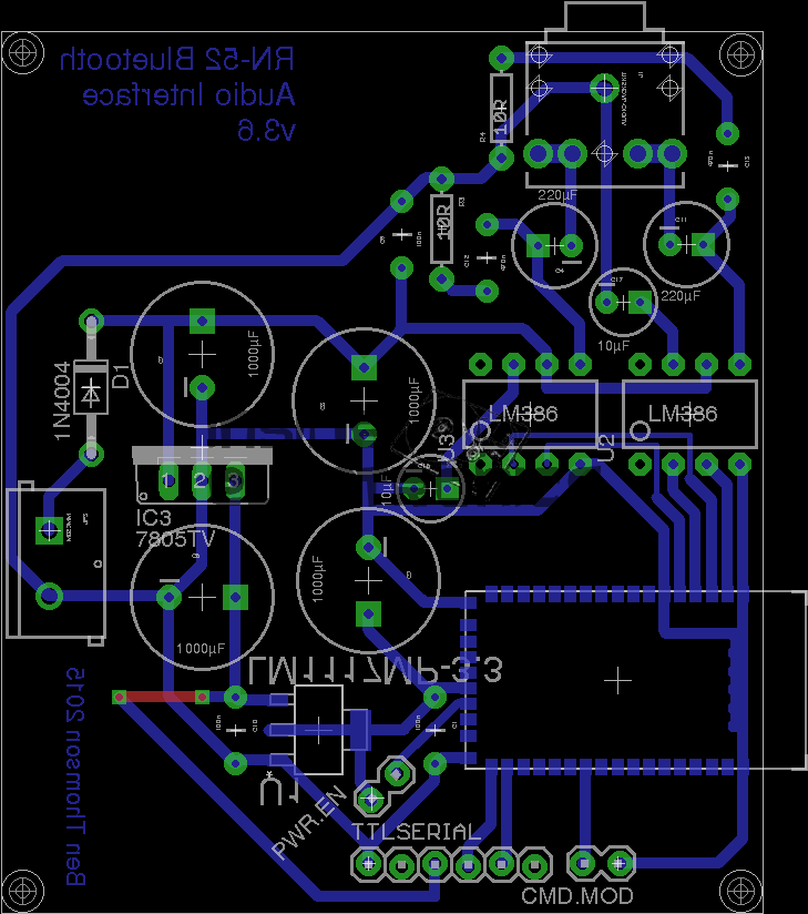
RN-52-SCH-v3.6RN-52-PCB-v3.6
[download id=”5579″]
Tip Jar
If you’ve found my content useful, please consider leaving a donation by clicking the Tip Jar below!
All collected funds go towards new content & the costs of keeping the server online.