Posted on Leave a comment

Blog Housekeeping & Changes

It occurred to me the other day that I’ve been running this blog now for over 10 years! This is the second iteration, as the first was lost in a server crash shortly after it went live. (Wasn’t so good with backups back then!). In that time the traffic to the blog has grown exponentially, who’d have thought that people would actually like reading most of the waffle that comes out of my brain! 😉

2020 Stats
2020 Stats

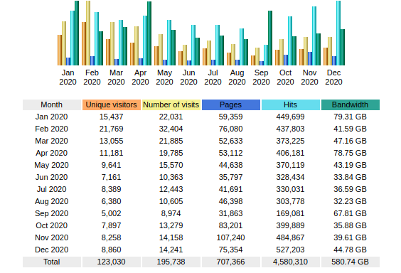
It seems the global Covid-19 Pandemic actually had an effect on my visitor numbers as well.

At the moment things are becoming a little cluttered on the back end, and there are a few errors that need sorting on the front end – thanks to some of my readers for pointing some of those out!

Site Theming

I’ve also been using the same theme for most of that time, but it’s beginning to show now with many updates over the years, and no updates to the theme code, that I’m going to start having some issues with the next versions of PHP, so this will have to change. This does join up with another project I have going, for a small webshop. The current theme unfortunately isn’t compatible with the most popular WordPress commerce plugins.

Broken Downloads

Thanks again to my readers for catching this one! It seems most of the downloads on the site have become broken, although I’m not sure why. I have changed over the Download plugin, and I am in the process of slowly moving over the shortcodes to the new system, so they will all be operational again.

On-Disk Size

Over the last decade or so of running, this blog has grown massively in size on disk – the usage currently stands at around 80GB. I really do need to reduce this footprint, so some time will have to be taken going through the backend filesystem to prune out any crap.

Posted on 2 Comments

Eberspacher D5W ECU Constant Overheat Error

Eberspacher ECU 25 1599 50 00 00

Here’s another Eberspacher control unit, this time from an ancient D5W 5kW water heater. The system in this case is just flaky – sometimes the heater will start without fault & run perfectly, then suddenly will stop working entirely.
The error codes are read on these very old units via an indicator lamp connected to a test terminal. In this case the code was the one for Overheat Shutdown.

Considering this fault occurs when the heater is stone cold, I figured it was either a fault with the sensor itself or the ECU.

Temperature Sensor
Temperature Sensor

The temperature sensor is located on the heat exchanger, right next to the hot water outlet fitting. I’m not sure what the spec is, but it reads exactly 1KΩ at room temperature.

ECU PCB
ECU PCB

The PCB is held into the aluminium can by means of crimps around the edge that lock into the plastic terminal cover. Inserting a screwdriver & expanding the crimps allows the PCB to be slid out.

Casing Crimps
Casing Crimps

The factory date stamp on the microcontroller dates this unit to March 1989 – considerably older than I expected!
Unlike the newer versions that use transistors, this ECU has a bunch of PCB relays to do the high current switching of the water pump motor, fan motor & glowplug.
Overall the board looks to be solidly constructed, with silicone around all the larger components.

ECU PCB Solder Side
ECU PCB Solder Side

Here’s the solder side of the PCB, which has a generous coating of sealant to keep moisture out.

Bad Joint Closeup
Bad Joint Closeup

Looking at the solder joints for the row of relays on the top side of the PCB, it looks like that there’s some dry joints here.
I suspect that years of vibration has taken it’s toll, as the relays are otherwise unsupported. It wouldn’t be possible to use silicone to secure these devices as they are completely open – any sealant would likely stop them from operating.

Resoldered Joints
Resoldered Joints

Using a very hot soldering iron I managed to get the joints to reflow properly, using lots of flux to make sure the conformal coating didn’t interfere with the reflow.

Posted on Leave a comment

Mini Teardown: Eberspacher 701 BT Controller

It’s well known that there are two versions of the 701 type controller available for Eberspacher heaters, the version with the blue logo is the official un-restricted model, while the version with the white logo is a version built for BT that restricts the heater to 1 hour runtime & has no diagnostics built in.
As these devices are microcontroller driven, I assumed that the hardware would be the same, only the code running in the micro being the bit that Eberspacher changed. This option would certainly have been the lowest cost.

Controller PCB Rear
Controller PCB Rear

Here’s the PCB removed from the plastic housing. There are definitely some differences that I can tell. As the un-restricted version has an extra wire for the diagnostic serial interface, and this board has no unpopulated parts, the PCB is definitely a different version.
In the centre is a Microchip PIC16C622 microcontroller, the OTP version in this case for cost reductions. (I may try reading the binary from this chip in the future, chances are it’s code protected though).
Below the micro is an NXP PCF8577C 32-segment LCD controller, this has an I²C interface to the PIC.
The temperature control function on these heaters is done via applying a resistance to one of the control lines, between 1750Ω-2180Ω, ±80Ω. (Very odd values these, not to mention no standard components can create this range easily, bloody engineers >_<). This is accomplished in hardware with a BU2092F I²C shift register from Rohm, which is connected to a bank of resistors. The microcontroller will switch combinations of these into the circuit to get the range of resistances required.
The rest of the circuit is local power regulation & filtering.

Controller PCB Front

There’s not much on the other side of the PCB, just the LCD itself & the contacts for the buttons.

Posted on Leave a comment

Raspberry Pi Timelapse Script

To make my timelapse video capture a little easier, I wrote a small script that handles creation of a new folder for every timelapse instance, deals with the runtime & frame interval flags & generally makes everything a little cleaner.

As with most of my code, it’s rough, but functional

#!/bin/bash

INPUTFILE="$1"
INPUTFILE+="_%d"
FRAME_INTERVAL="$2"
FRAME_INTERVAL_MIN="1250"
RUNTIME="2073600000"
DATE=$(date +"%T_%m-%d-%y")
if [ -z $1 ]
    then
		echo "Raspberry Pi Timelapse Script v1.2"
		echo "2015 Ben Thomson 2E0GXE"
		echo "Images will be taken in 1920x1080 format for transcoding into video."
		echo "This script expects some options in the following format:"
		echo "./timelapse.sh <File Prefix> <Frame Interval>"
		echo "<File Prefix> The script will prepend this name to every image as a unique capture session identifier."
		echo "A sequential number is appended to the end of the filename for frame identification."
		echo "<Frame Interval> This is the interval between frames, in milliseconds. Minimum 1250."
		echo "This minimum is required to retain stability & prevent dropped frames."
		echo "Every time the program is started, a new folder with the current date & time is created for the images."
		exit 0
fi
if [ $FRAME_INTERVAL -lt $FRAME_INTERVAL_MIN ]
	then
		echo Frame Interval Too Low!
		echo This will cause dropped frames! Exiting!
		exit 0
fi

mkdir -p ./$DATE-$1
echo Image Folder $DATE-$1 Created
echo Image Capture Interval $FRAME_INTERVAL ms 
echo Starting Timelapse Capture... CTRL+C To Exit...
raspistill -k -n -ex auto -awb auto -mm average -w 1920 -h 1080 -o ./$DATE-$1/$INPUTFILE.jpg -tl $FRAME_INTERVAL -t $RUNTIME

echo Timelapse Complete!
echo File Prefix: $INPUTFILE
echo Frame Interval: $FRAME_INTERVAL ms
echo Folder Name: $DATE-$1

[download id=”5593″]

Posted on 3 Comments

Arduino Based SWR/PWR Meter – The Board

I recently posted about a small analog SWR/Power meter I got from eBay, and figured it needed some improvement.

After some web searching I located a project by ON7EQ, an Arduino sketch to read SWR & RF power from any SWR bridge.
The Arduino code is on the original author’s page above, his copyright restrictions forbid me to reproduce it here.

I have also noticed a small glitch in the code when it is flashed to a blank arduino: The display will show scrambled characters as if it has crashed. However pushing the buttons a few times & rebooting the Arduino seems to fix this. I think it’s related to the EEPROM being blank on a new Arduino board.

I have run a board up in Eagle for testing, shown below is the layout:

SWR Meter SCH
SWR Meter SCH

The Schematic is the same as is given on ON7EQ’s site.
Update: ON7EQ has kindly let me know I’ve mixed up R6 & R7, so make sure they’re switched round when the board is built ;). Fitting the resistors the wrong way around may damage the µC with overvoltage.

SWR Meter PCB
SWR Meter PCB

Here’s the PCB layout. I’ve kept it as simple as possible with only a single link on the top side of the board.

PCB Top
PCB Top

Here’s the freshly completed PCB ready to rock. Arduino Pro mini sits in the center doing all the work.
The link over to A5 on the arduino can be seen here, this allows the code to detect the supply voltage, useful for battery operation.
On the right hand edge of the PCB are the pair of SMA connectors to interface with the SWR bridge. Some RF filtering is provided on the inputs.

PCB Bottom
PCB Bottom

Trackside view of the PCB. This was etched using my tweaked toner transfer method.

LCD Fitted
LCD Fitted

Here the board has it’s 16×2 LCD module.

Online
Online

Board powered & working. Here it’s set to the 70cm band. The pair of buttons on the bottom edge of the board change bands & operating modes.
As usual, the Eagle layout files are available below, along with the libraries I use.

[download id=”5585″]

[download id=”5573″]

More to come on this when some components arrive to interface this board with the SWR bridge in the eBay meter.

Posted on Leave a comment

uRadMonitor – Node Online!

It’s official. I’m now part of the uRadMonitor network, & assisting in some of the current issues with networking some people (including myself) have been having.

It seems that the uRadMonitor isn’t sending out technically-valid DHCP requests, here is what Wireshark thinks of the DHCP on my production network hardware setup:

WireShark Screencap
WireShark Screencap

As can be seen, the monitor unit is sending a DHCP request of 319 bytes, where a standard length DHCP Request packet should be ~324 bytes, as can be seen on the below screen capture.

Valid DHCP
Valid DHCP

This valid one was generated from the same SPI Ethernet module as the monitor, (Microchip ENC28J60) connected to an Arduino. Standard example code from the EtherCard library was used to set up the DHCP. The MAC address of the monitor was also cloned to this setup to rule out the possibility of that being the root cause.

My deductive reasoning in this case points to the firmware on the monitor being at fault, rather than the SPI ethernet hardware, or my network hardware. Radu over at uRadMonitor is looking into the firmware being at fault.

Strangely, most routers don’t seem to have an issue with the monitor, as connecting another router on a separate subnet works fine, and Wireshark doesn’t even complain about an invalid DHCP packet, although it’s exactly the same.

Working DHCP
Working DHCP

As the firmware for the devices isn’t currently available for me to pick apart & see if I can find the fault, it’s up to Radu to get this fixed at the moment.

Now, for a µTeardown:

uRadMonitor
uRadMonitor

Here is the monitor, a small aluminium box, with power & network.

PCB
PCB

Removing 4 screws in the end plate reveals the PCB, with the Geiger-Mueller tube along the top edge. My personal serial number is also on the PCB.
The ethernet module is on the right, with the DC barrel jack.

PCB Bottom
PCB Bottom

Here is the bottom of the PCB, with the control MCU & the tiny high voltage inverter for the Geiger tube.

Control Electronics
Control Electronics

A Closeup of the main MCU, an ATMega328p

Logo
Logo

PCB Logo. Very artsy 😉

Posted on Leave a comment

Raspberry Pi Geiger Counter

Geiger Counter Setup

Here’s my latest project with the Pi: interfacing it with the Sparkfun Geiger counter & outputting the resulting data to a character LCD.

The geiger counter is interfaced with it’s USB port, with the random number generator firmware. A Python script reads from the serial port & every minute outputs CPM & µSv/h data to the display.

The Python code is a mash of a few different projects I found online, for different geiger counters & some of my own customisations & code to write the info to the display & convert CPM into µSv/h.

This also writes all the data into a file at /var/log/radlog.txt

The code for this is below:

import time
import sys
import serial
import os
import RPIO
from RPLCD import CharLCD
from subprocess import * 
from datetime import datetime

# configuration settings

logfile = "/var/log/radlog" # location to save log data
serial_port = "/dev/ttyUSB0"
lcd = CharLCD(pin_rs=15, pin_rw=18, pin_e=16, pins_data=[21, 22, 23, 24], numbering_mode=RPIO.BOARD, cols=16, rows=4, dotsize=10) #Init LCD with physical parameters

f = open(logfile,"a")

ser = serial.Serial(serial_port,9600,timeout=1)

one = 0

#Init LCD with initial values.
lcd.cursor_pos = (0, 1)
lcd.write_string("Geiger Counter")
lcd.cursor_pos = (1, 2)
lcd.write_string("Initializing")
lcd.cursor_pos = (2,-3)
lcd.write_string("Please Wait...")
lcd.cursor_pos = (3, 0)
lcd.write_string(str(0) +" uSv/h")
f.write("Geiger Counter Initialized\n")
f.flush()
while 1==1:
  stamp = int(time.time())
  stamp == round(stamp,0)
  stamp = stamp + 60
  count = 0  
  while 1==1:
      ct = int(time.time())
      ct == round(ct,0)
      if ct > stamp:  break
      #Read from serial port
      bit = ser.read(1)
      if bit != "":
          count = count + 1
          #Conversion of counts per minute to uSv/hr
          usvh = count * 0.01
  at = str(time.asctime())
  t = str(time.time())
  #Write line to log file & print info to console
  f.write("["+at+"."+t+"] "+str(count) + " CPM " +str(usvh) + " uSv/h\n")
  f.flush()
  print "["+at+"."+t+"] Count "+str(count) + " " + str(usvh) +" uSv/hr"
  #Send measurement info to LCD
  lcd.clear()
  lcd.cursor_pos = (0, 0)
  lcd.write_string(datetime.now().strftime('%b %d  %H:%M:%S\n'))
  lcd.cursor_pos = (1, 0)
  lcd.write_string("Radiation Level:")
  lcd.cursor_pos = (2, 1)
  lcd.write_string(str(count) +" CPM")
  lcd.cursor_pos = (3, -1)
  lcd.write_string(str(usvh) +" uSv/h")
Info Display
Info Display
Posted on Leave a comment

RasPi Terminal Customisations


As seen in the previous post, the SSH terminal of my Pi gives some useful stats. This is done using GNU Screen, with a custom config file.

This file is .screenrc in your user’s home folder. My personal code is posted below:

I have uploaded the pair of scripts for the backticks, and they can be found here:

mem.sh
disk.sh

More to come once my new 16GB Class 10 SD Card arrives!

Posted on Leave a comment

Nokia 7110

Front
Front

Another phone from the mid 90s. This is the nokia 7110.

Slider Open
Slider Open

Here the slider is open showing the keypad.

Battery Removed
Battery Removed

Here the battery is removed, a Li-Ion unit.

Battery
Battery

The battery cell & protection circuit removed from the casing.

Rear Of PCB
Rear Of PCB

This is the rear of the PCB removed from the housing. Data & charging ports on the right hand side f the board.

Front Of PCB
Front Of PCB

Front of the PCB with the RF sections at the left hand side & the keypad contacts on the right.

RF Sections
RF Sections

Closeup of the RF sections of the board, big silver rectangular cans are VCO units.

SIM Connector
SIM Connector

Closeup of the top rear section of the PCB, with SIM cnnector, battery contacts, IR tranciever at the far left. Bottom centre is the external antenna connector.

CPU
CPU

The logic section of the board, Large chip is CPU, to right of that is the ROM storing the machine code. Other chips are unknown custom parts.

Mic & Speaker
Mic & Speaker

The Mic & the loudspeaker removed from it’s housing.

LCD
LCD

LCD from the front of the unit, SPI interfaced. Flex PCB also contains the power button, loudspeaker contacts & a temperature sensor.

Scroll Wheel
Scroll Wheel

The scroll wheel removed from the front housing.

Vibra-Motor
Vibra-Motor

Tiny vibration motor removed from the rear housing, alerts the user to a text or phone call.