The Shack

The Shack

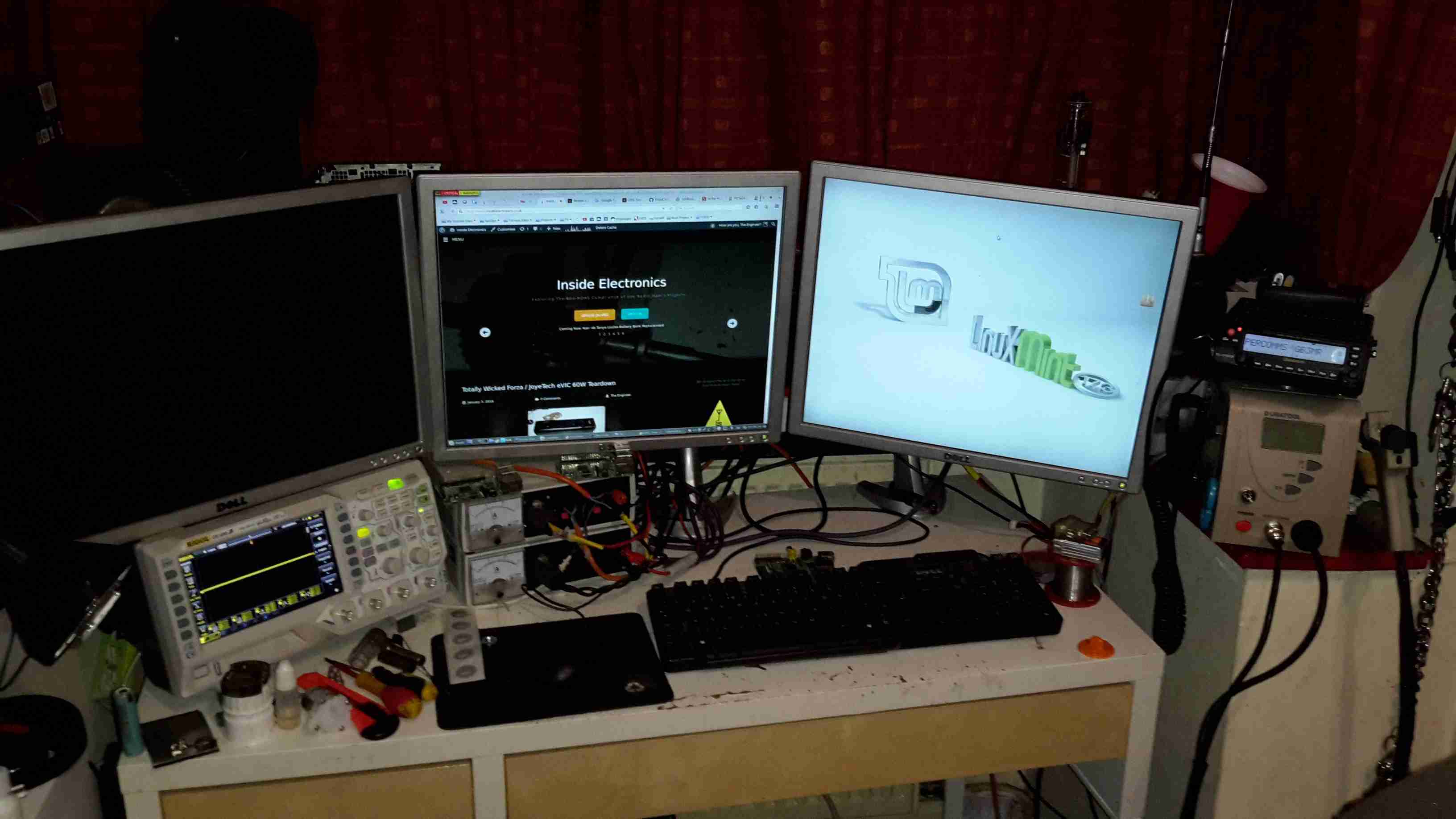
So, here is where all the action happens.

Main radio of course is housed on the left, it’s partially hidden under my currently over-populated breadboard.

All 3 monitors are linked to the same PC, using a pair of video cards. This is a very flexible system with so much screen real estate.

Main system power is provided by the pair of power supplies next to the radio – these are homebrew units using surplus switched mode PSU boards. Check my previous posts for more details.

Power Supplies
Power Supplies

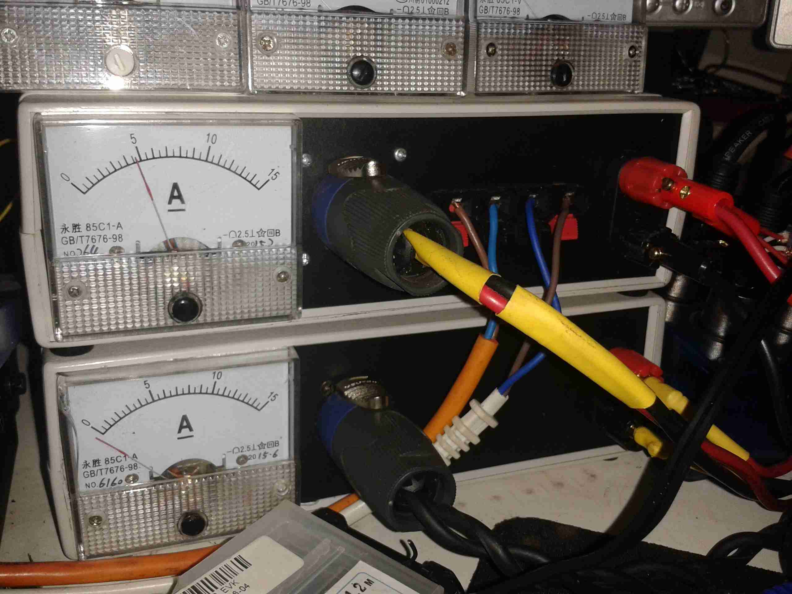
The main power supply system. These two supplies are cross connected, giving a total DC amperage of 30A at 13.8v. There is also a link to a large 220Ah lead-acid battery bank (orange cable), to keep me on the air during power outages. This cable is getting upgraded to something more beefy shortly. The white cable is currently supplying power to my online radiation monitor.
The main high-current DC outputs are the Speakon connectors next to the meters. The top one is powering the radio directly, the bottom is linked through to my 12v distribution box for lower current loads, such as the oscilloscope, audio amplifiers, tools, etc.

Radiation Monitor
Radiation Monitor

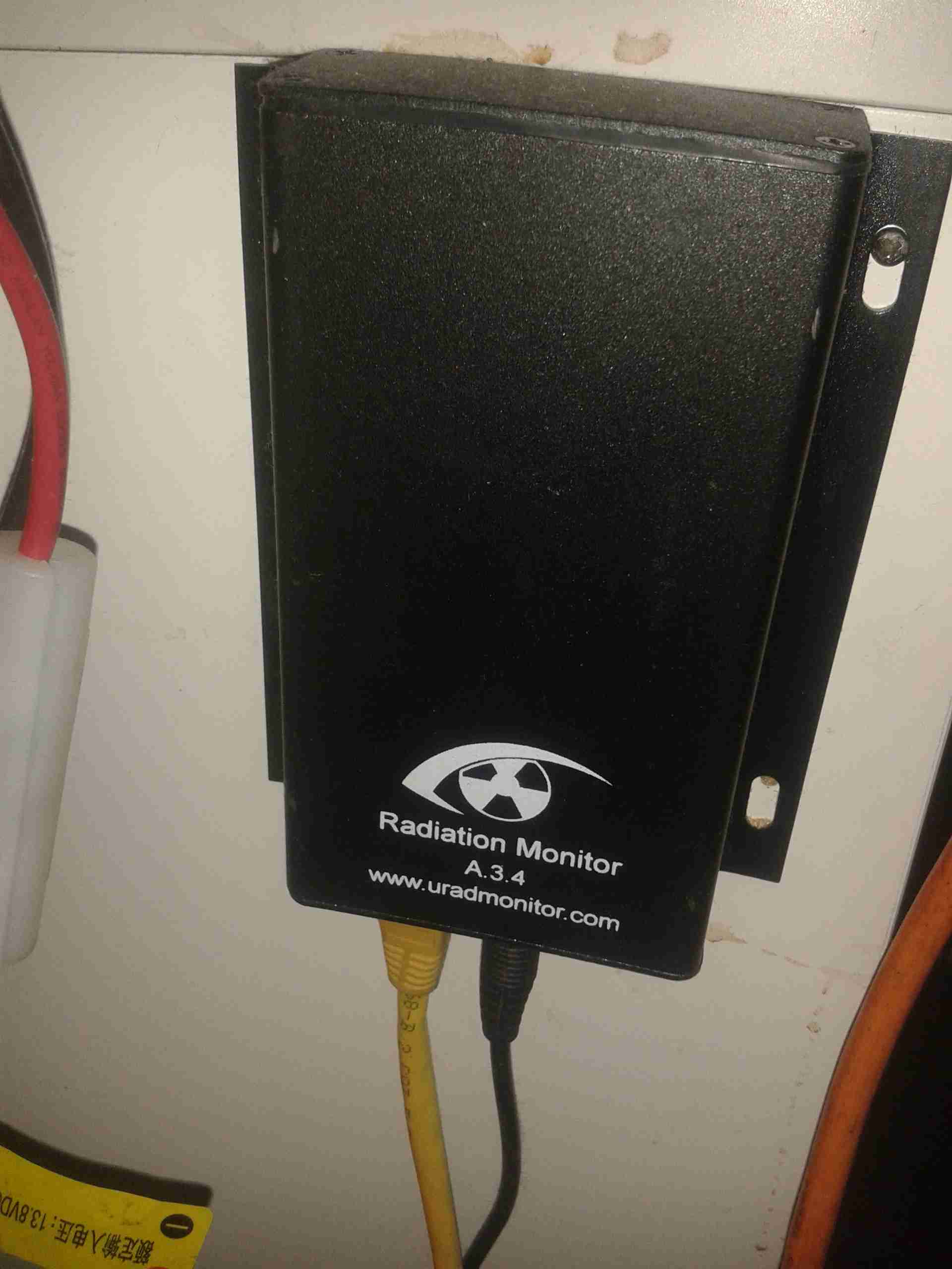
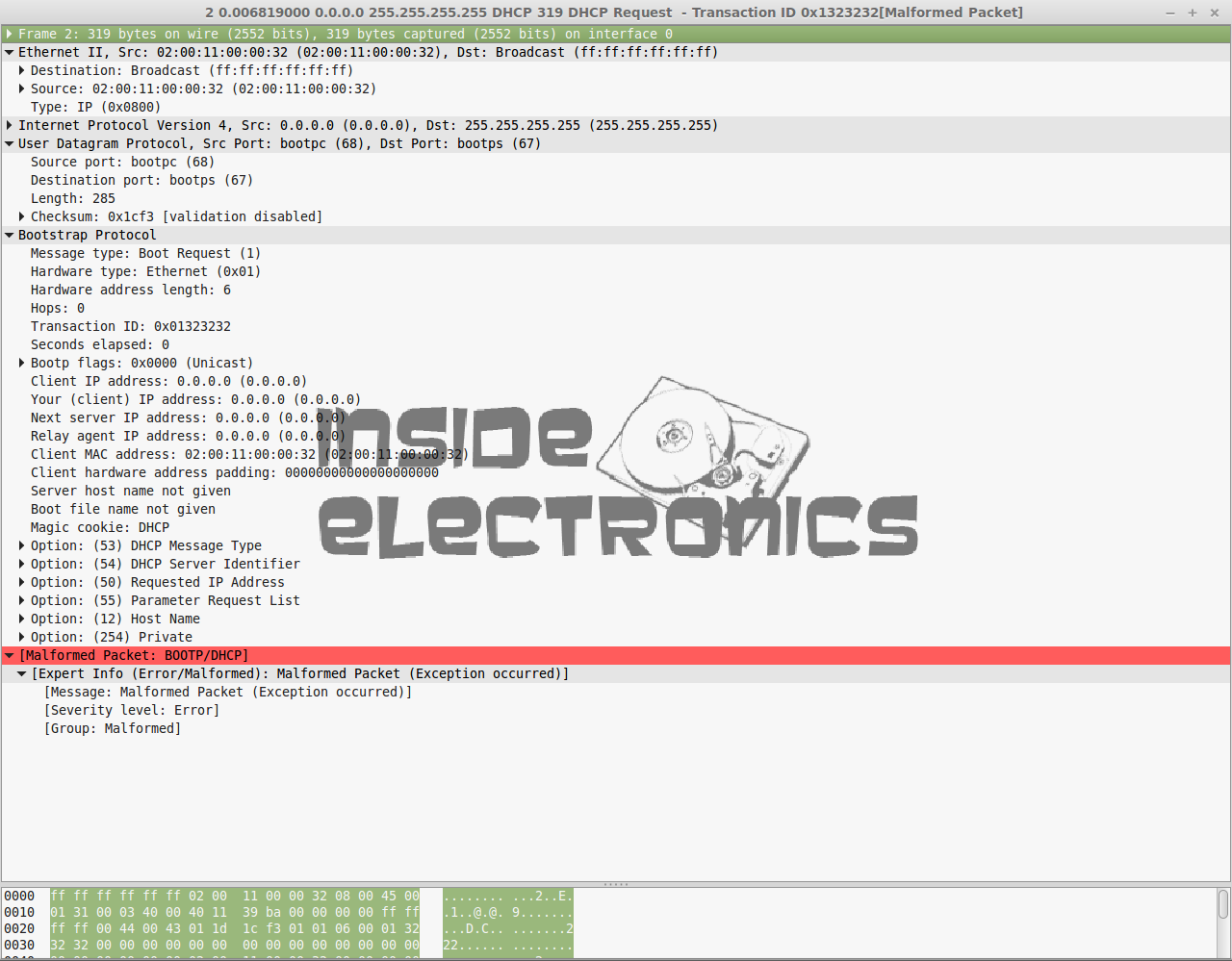
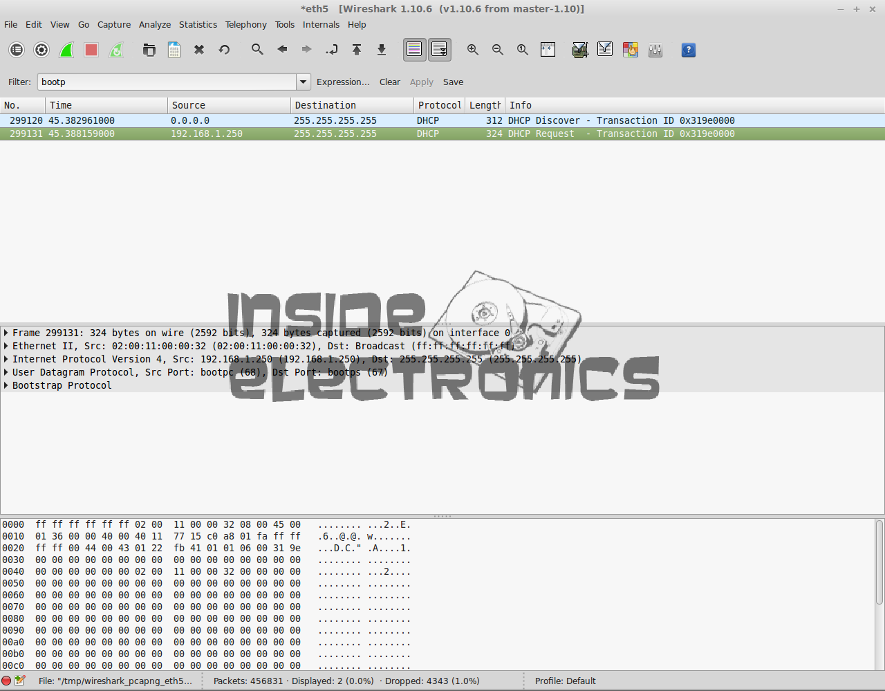
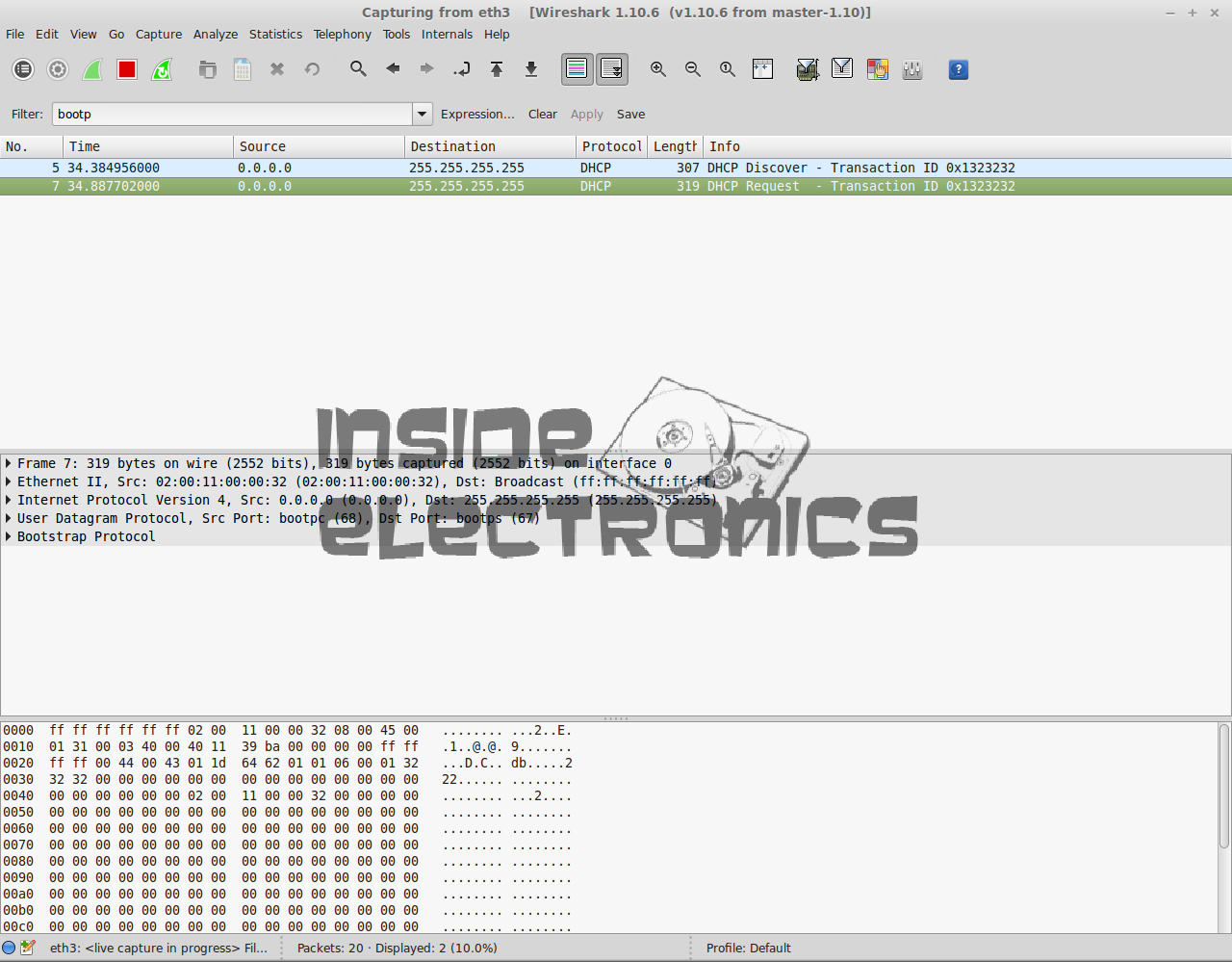
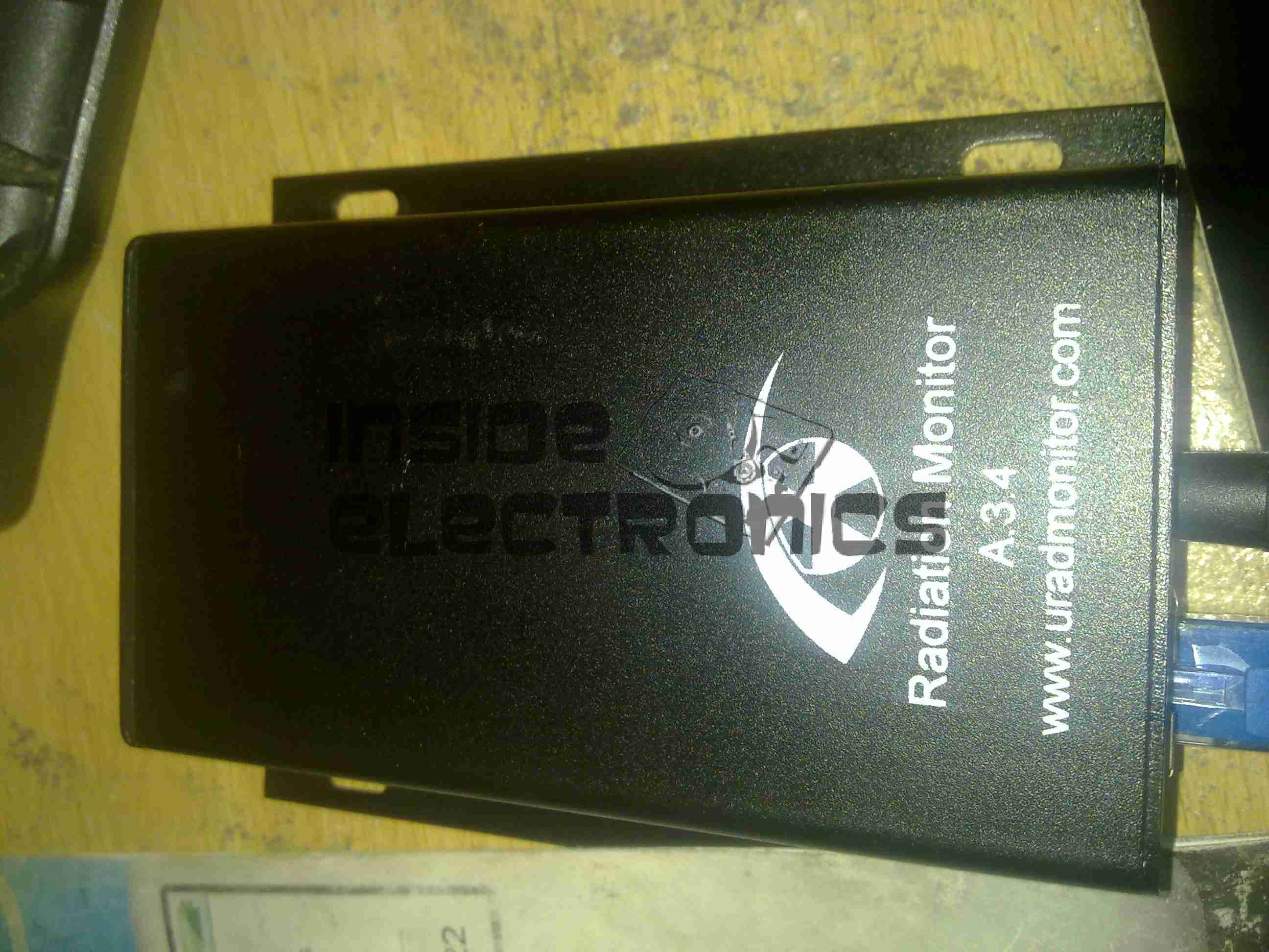
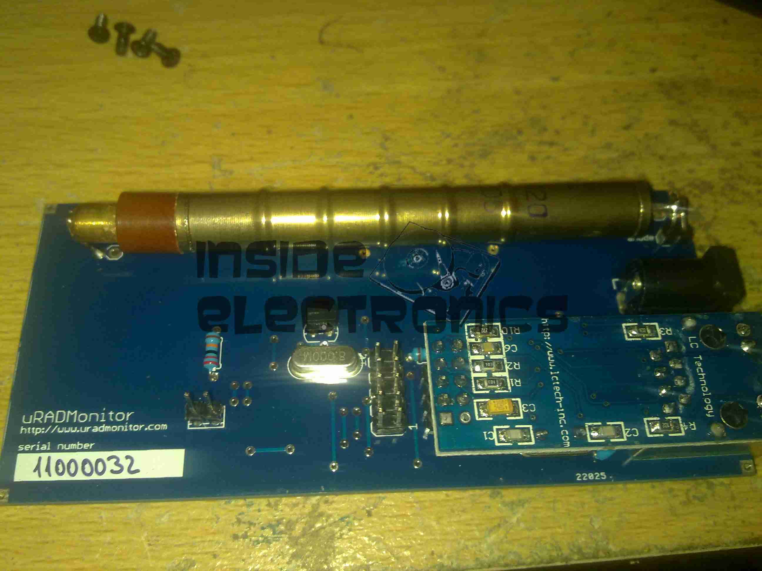
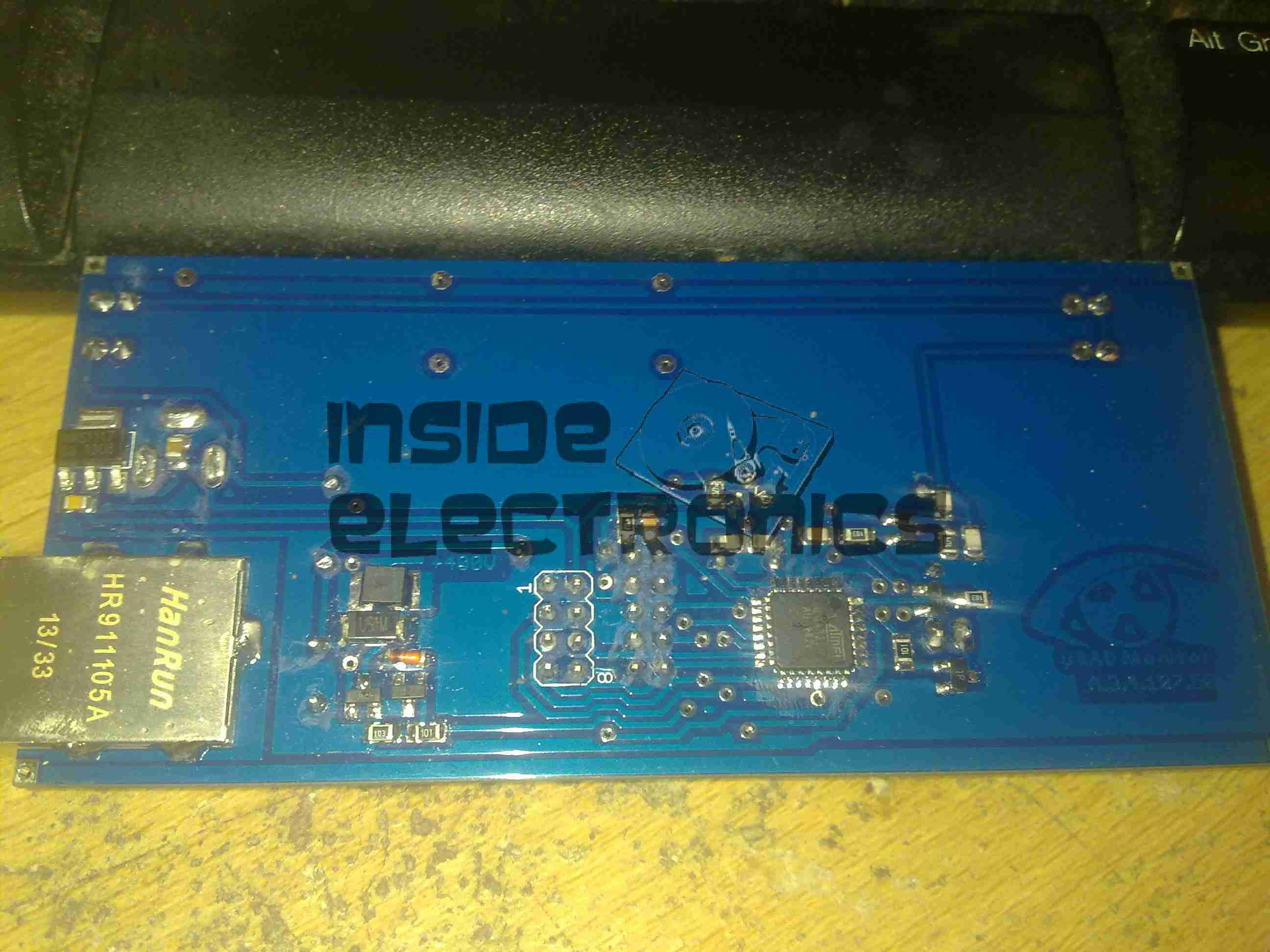
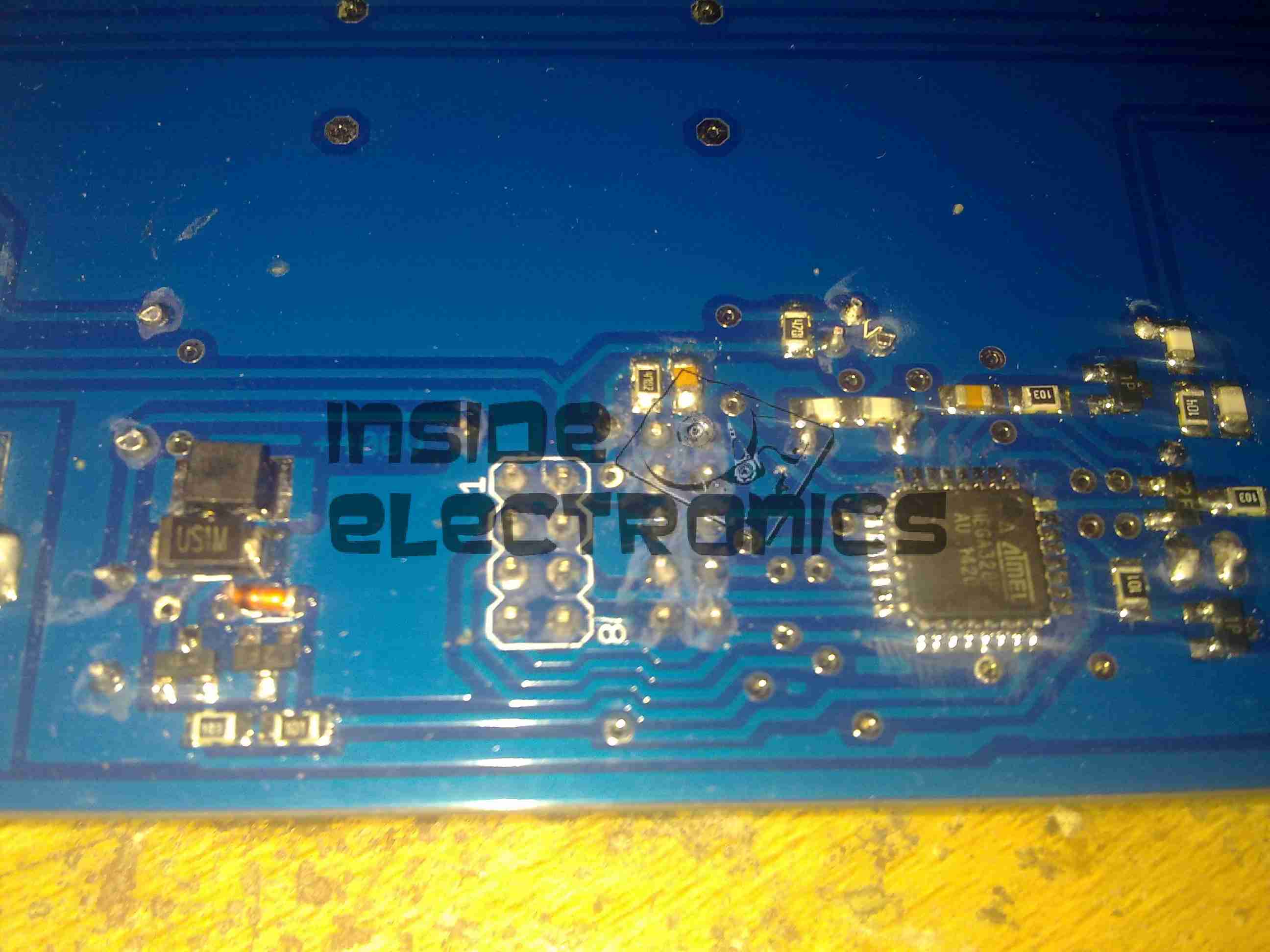
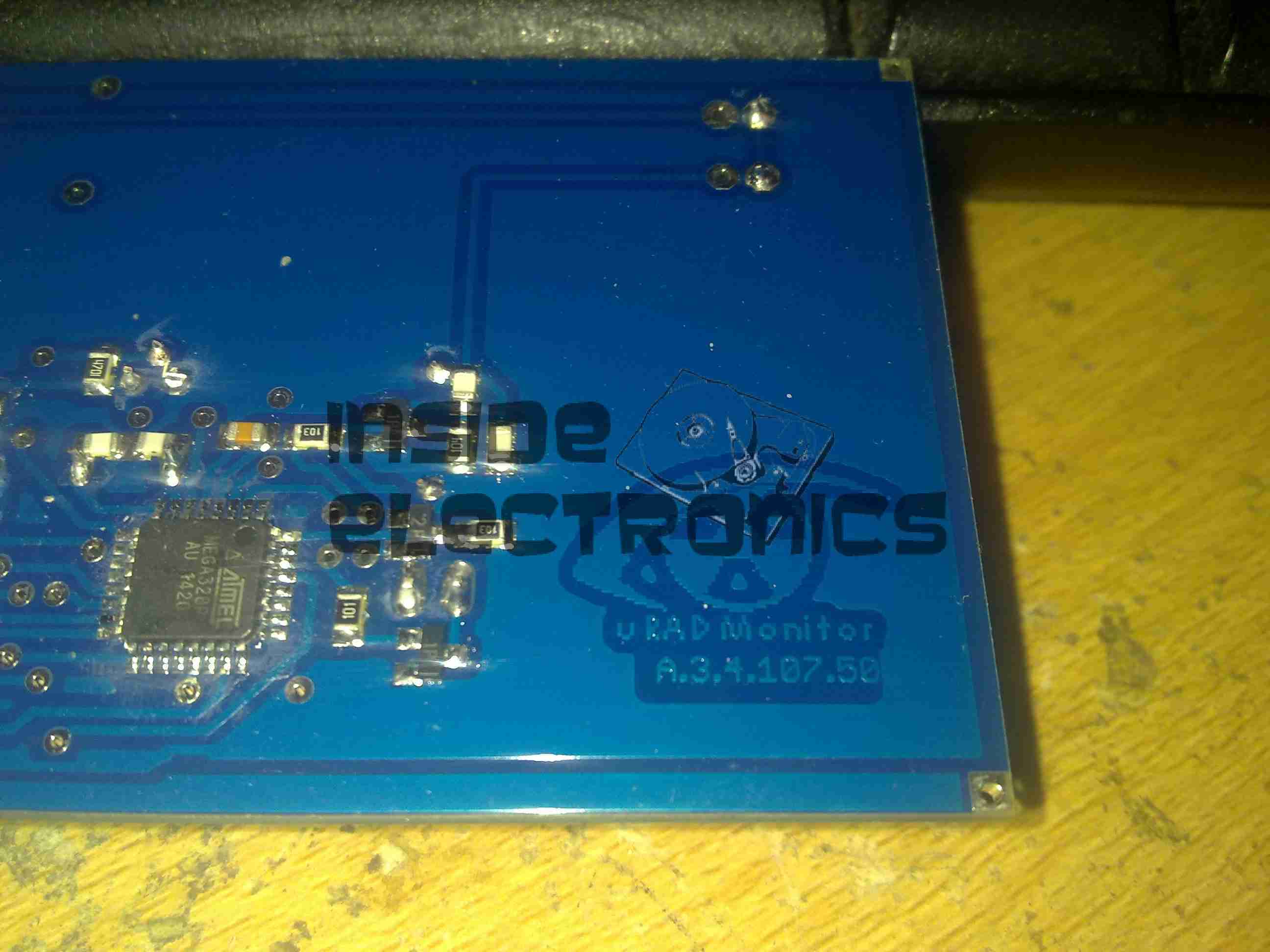
Attached to the side of the desk is the radiation monitor itself.

Core NAS
Core NAS

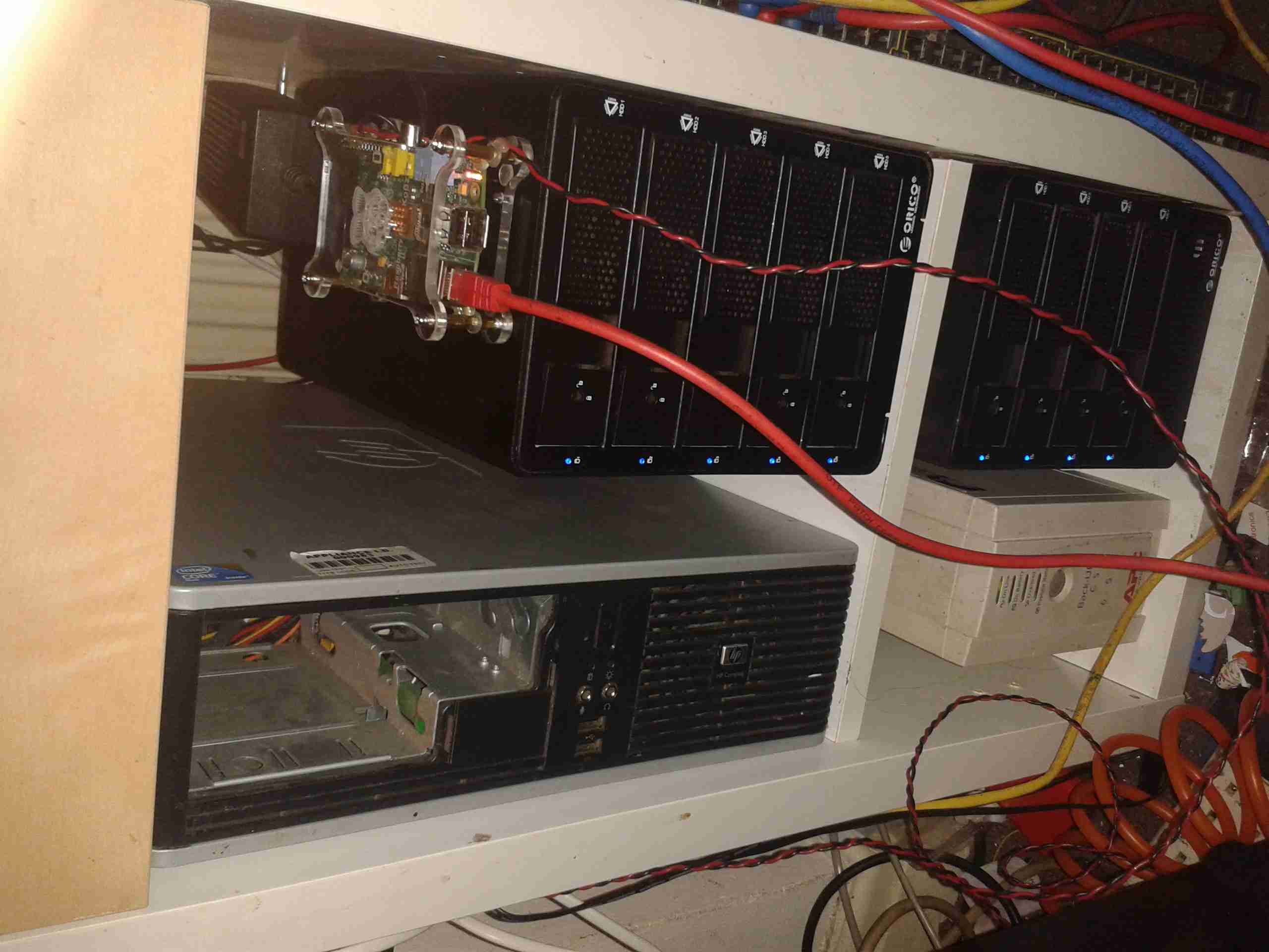
Under the radio is the core NAS of the network. It’s an array of 9 4TB disks, in RAID6, giving a total capacity after parity of 28TB. This provides storage & services to every other machine in the shack, the Raspberry Pi on top of the disk array is doing general network housekeeping & monitoring, also generating the graphs for the Radiation Monitor page. A Cisco 48-port switch is partially out of frame on the right, providing 100MB Ethernet to the devices that don’t require gigabit.

Posted on Leave a comment

uRadMonitor – Node Online!

It’s official. I’m now part of the uRadMonitor network, & assisting in some of the current issues with networking some people (including myself) have been having.

It seems that the uRadMonitor isn’t sending out technically-valid DHCP requests, here is what Wireshark thinks of the DHCP on my production network hardware setup:

WireShark Screencap
WireShark Screencap

As can be seen, the monitor unit is sending a DHCP request of 319 bytes, where a standard length DHCP Request packet should be ~324 bytes, as can be seen on the below screen capture.

Valid DHCP
Valid DHCP

This valid one was generated from the same SPI Ethernet module as the monitor, (Microchip ENC28J60) connected to an Arduino. Standard example code from the EtherCard library was used to set up the DHCP. The MAC address of the monitor was also cloned to this setup to rule out the possibility of that being the root cause.

My deductive reasoning in this case points to the firmware on the monitor being at fault, rather than the SPI ethernet hardware, or my network hardware. Radu over at uRadMonitor is looking into the firmware being at fault.

Strangely, most routers don’t seem to have an issue with the monitor, as connecting another router on a separate subnet works fine, and Wireshark doesn’t even complain about an invalid DHCP packet, although it’s exactly the same.

Working DHCP
Working DHCP

As the firmware for the devices isn’t currently available for me to pick apart & see if I can find the fault, it’s up to Radu to get this fixed at the moment.

Now, for a µTeardown:

uRadMonitor
uRadMonitor

Here is the monitor, a small aluminium box, with power & network.

PCB
PCB

Removing 4 screws in the end plate reveals the PCB, with the Geiger-Mueller tube along the top edge. My personal serial number is also on the PCB.
The ethernet module is on the right, with the DC barrel jack.

PCB Bottom
PCB Bottom

Here is the bottom of the PCB, with the control MCU & the tiny high voltage inverter for the Geiger tube.

Control Electronics
Control Electronics

A Closeup of the main MCU, an ATMega328p

Logo
Logo

PCB Logo. Very artsy 😉