Posted on Leave a comment

Securing The New Server & Security In General

This was originally going to be part of another post, but it ended up getting more complex than I originally intended so it’s been given it’s own. I go into into many of my personal security practices, on both my public facing servers & personal machines. Since the intertubes are so central to life these days, good security is a must, especially since most people use the ‘net to do very sensitive operations, such as banking, it’s becoming even more essential to have strong security.

Since bringing the new server online & exposing it to the world, it’s been discovered in record time by the scum of the internet, SSH was under constant attack within 24 hours, and within that time there were over 20,000 failed login attempts in the logs.
This isn’t much of an issue, as I’ve got a strong Fail2Ban configuration running which at the moment is keeping track of some 30 IP addresses that are constantly trying to hammer their way in. No doubt these will be replaced with another string of attacks once they realise that those IPs are being dropped. I also prevent SSH login with passwords – RSA keys only here.
MySQL is the other main target to be concerned about – this is taken care of by disabling root login remotely, and dropping all MySQL traffic at the firewall that hasn’t come from 127.0.0.1.

Keeping the SSH keys on an external device & still keeping things simple just requires some tweaking to the .bashrc file in Linux:

This little snippet makes the ssh client look somewhere else for the keys themselves, while keeping typing to a minimum in the Terminal. This assumes the external storage with the keys always mounts to the same location.

Everything else that can’t be totally blocked from outside access (IMAP, SMTP, FTP, etc), along with Fail2Ban protection, gets very strong passwords, unique to each account, (password reuse in any situation is a big no-no) and where possible TOTP-based two factor authentication is used for front end stuff, all the SSH keys, master passwords & backup codes are themselves kept offline, on encrypted storage, except for when they’re needed. General password management is taken care of by LastPass, and while they’ve been subject to a couple of rather serious vulnerabilities recently, these have been patched & it’s still probably one of the best options out there for a password vault.
There’s more information about those vulnerabilities on the LastPass blog here & here.


This level of security paranoia ensures that unauthorized access is made extremely difficult – an attacker would have to gain physical access to one of my mobile devices with the TOTP application, and have physical access to the storage where all the master keys are kept (along with it’s encryption key, which is safely stored in Meatware), to gain access to anything.
No security can ever be 100% perfect, there’s always going to be an attack surface somewhere, but I’ll certainly go as far as is reasonable, while not making my access a total pain, to keep that attack surface as small as possible,and therefore keeping the internet scum out of my systems.
The last layer of security is a personal VPN server, which keeps all traffic totally encrypted while it’s in transit across my ISP’s network, until it hits the end point server somewhere else in the world. Again, this isn’t perfect, as the data has to be decrypted *somewhere* along the chain.

Posted on Leave a comment

Website Hosting Updates!

Over the past few weeks, the host I’ve been with for over 3 years, OVH, announced a rather large price increase of 20% because of Brexit – the current universal excuse to squeeze the customer for more cash. This change has sent the price of my dedicated server solution with them to over £45 a month. Doing some napkin-calculation gave me £18 a month in extra power to run a small server locally. So I’ve decided to bring the hosting solution back to my local network & run from my domestic internet link, which at 200Mbit/s DL & 20Mbit/s UL should be plenty fast enough to handle the modest levels of traffic I usually get.

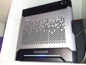
Obviously, some hardware was required for this, so I obtained this beauty cheap on eBay:

HP MicroServer Gen 8
HP Proliant MicroServer Gen 8

This is a Gen 8 HP Proliant Microserver, very small & quiet, perfect for the job. This came with 4GB of RAM installed from the factory, and a Celeron G1610T running at 2.3GHz. Both are a little limited, so some upgrades will be made to the system.

Disk Bays
Disk Bays

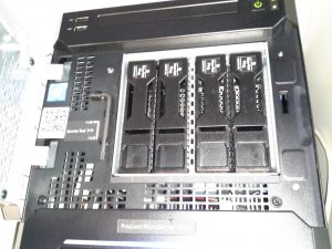
4 SATA drive bays are located behind the magnetically-locked front door, there’s a 250GB boot disk in here along with a pair of 500GB disks in RAID1 to handle the website files & databases. For my online file hosting site, the server has a backend NFS link direct to Volantis – my 28TB storage server. This arrangement keeps the large file storage side of things off the web server disks & on a NAS, where it should be.

Extra RAM
Extra RAM

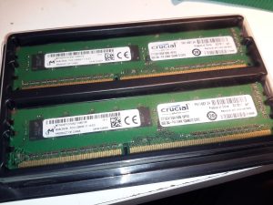
First thing is a RAM upgrade to the full supported capacity of 16GB. This being a Proliant server machine, doesn’t take anything of a standard flavour, it’s requirements are DDR3-10600E or DDR3-12800E (the E in here being ECC). This memory is both eye-wateringly expensive & difficult to find anywhere in stock. It’s much cheaper & easier to find the ECC Registered variety, but alas this isn’t compatible.

Over the past 48 hours or so, I’ve been migrating everything over to the new baby server, with a couple of associated teething problems, but everything seems to have gone well so far. The remaining job to get everything running as it should is an external mail relay – sending any kind of email from a dynamic IP / domestic ISP usually gets it spam binned by the big providers instantly, regardless of it actually being spam or not – more to come on that setup & configuring postfix to use an external SMTP relay server soon!

If anyone does find something weird going on with the blog, do let me know via the contact page or comments!

The Shack

The Shack

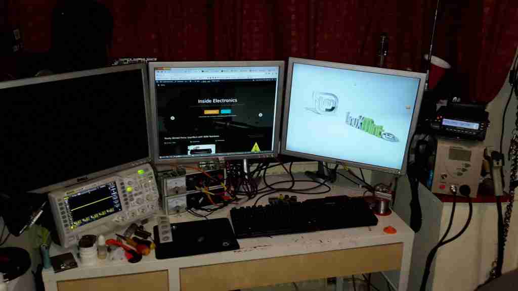
So, here is where all the action happens.

Main radio of course is housed on the left, it’s partially hidden under my currently over-populated breadboard.

All 3 monitors are linked to the same PC, using a pair of video cards. This is a very flexible system with so much screen real estate.

Main system power is provided by the pair of power supplies next to the radio – these are homebrew units using surplus switched mode PSU boards. Check my previous posts for more details.

Power Supplies
Power Supplies

The main power supply system. These two supplies are cross connected, giving a total DC amperage of 30A at 13.8v. There is also a link to a large 220Ah lead-acid battery bank (orange cable), to keep me on the air during power outages. This cable is getting upgraded to something more beefy shortly. The white cable is currently supplying power to my online radiation monitor.
The main high-current DC outputs are the Speakon connectors next to the meters. The top one is powering the radio directly, the bottom is linked through to my 12v distribution box for lower current loads, such as the oscilloscope, audio amplifiers, tools, etc.

Radiation Monitor
Radiation Monitor

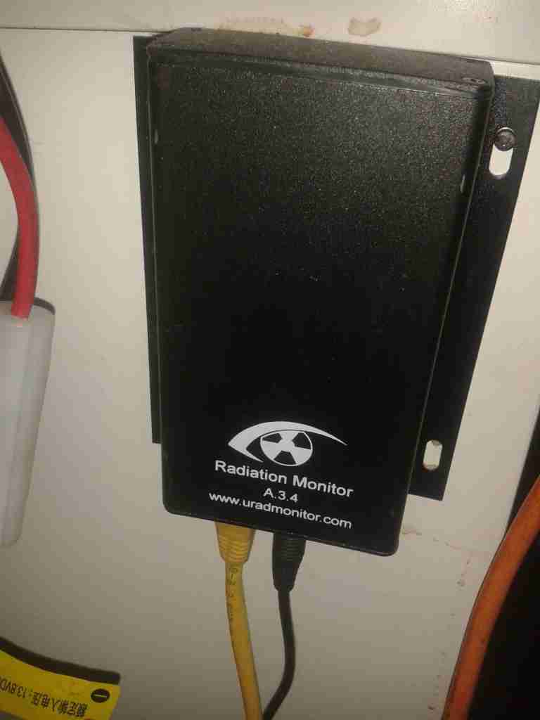
Attached to the side of the desk is the radiation monitor itself.

Core NAS
Core NAS

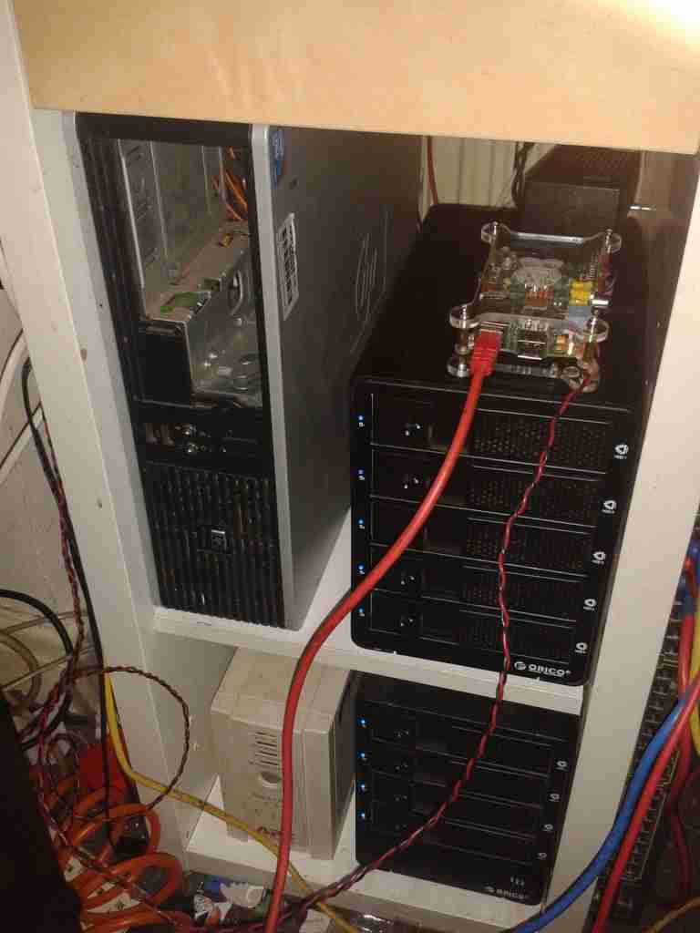
Under the radio is the core NAS of the network. It’s an array of 9 4TB disks, in RAID6, giving a total capacity after parity of 28TB. This provides storage & services to every other machine in the shack, the Raspberry Pi on top of the disk array is doing general network housekeeping & monitoring, also generating the graphs for the Radiation Monitor page. A Cisco 48-port switch is partially out of frame on the right, providing 100MB Ethernet to the devices that don’t require gigabit.

Posted on Leave a comment

QSO Logging Systems

As per my site update post, I have migrated my radio log onto a new system, from CQRLOG.

CQR log has served me well since I first started in Amateur Radio, however it’s a bit complex to use, requires a backend MySQL server for it’s database, and as it’s a local application, it’s not possible to share my log with other Hams without some difficulty.
The only other major system with an online logging system is QRZ, and I find that particular site a bit of a pain, and many of the features there aren’t free. (Although it’s not horrendously expensive, I’m on a very tight budget & I must save where I can).

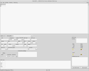
CQRLOG
CQRLOG Screenshot

Because of these points, I went on a search for something that would better serve my needs. I have discovered during this search that there’s liitle out there in the self-hosted respect.

I did however find Cloudlog, a web based logging system in PHP & MySQL.
This new system allows integration with the main site, as I can run it on the same server & LAMP stack, it’s very simple to use, is visually pleasing and it even generates a Google Map view of recent QSO locations.
It will also allow me to save some resources on my main PC, running a full-blown MySQL server in the background just for a single application is resource intensive, and a bit of a waste of CPU cycles. (CQRLOG and it’s associated MySQL server is 300MB of disk space, CloudLog is 27MB).

Backups are made simpler with this system also, as it’s running on my core systems, incremental backups are taken every 3 hours, with a full system backup every 24 hours. Combined with offsite backup sync, data loss is very unlikely in any event. All this is completely automatic.
I can also take an ADIF file from Cloudlog for use with any other logging application, if the need arises.

Cloudlog is built & maintained by Peter Goodhall, 2E0SQL.
From the looks of Github, there’s also a version 2 in development, although now I have version 1 up & running, I might just stick with it, unless an easy upgrade path is available.

When I am not operating mobile, new QSOs should appear in this system almost immediately, with their respective pins on the map. (These are generated by the Grid Square location, so accuracy may vary).
If you’ve spoken to me on the air & I haven’t updated it, I’m most likely away from an internet connection, in which case your callsign will appear as soon as I have access.

73s for now folks!

Posted on Leave a comment

uRadMonitor Network

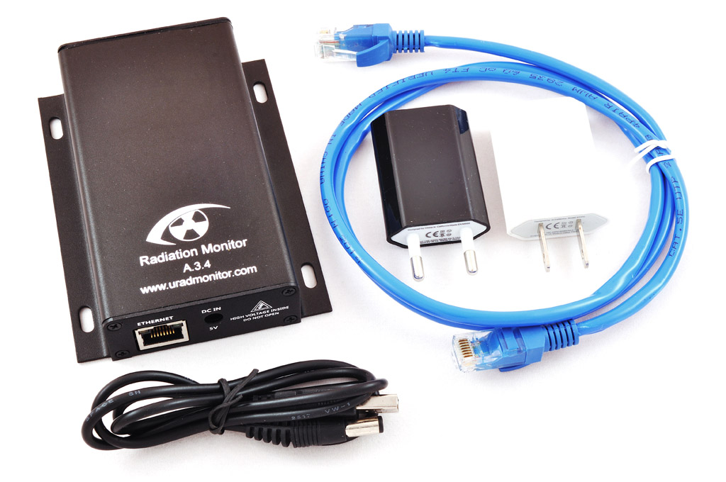
I’ve joined the uRadMonitor network! I’m told my unit is on the way & it should be going live here in Manchester, UK within about 10 days.

uRadMonitor Unit
uRadMonitor Unit

This is a crowd project to monitor background radiation levels all over the world, so far there’s a lot of units already online.

More to come once my unit arrives!

Posted on Leave a comment

HPI Nitrostar F4.6 Ignition Conversion

As there was no other online example of someone converting a glow/nitro car engine onto CDI ignition, I thought I would document the highlights here.
The engine is currently still running on glow fuel, but when the required fuel lines arrive I will be attempting the switch over to 2-Stroke petrol mix. This should definitely save on fuel costs.

The engine in this case is a HPI NitroStar F4.6 nitro engine, from a HPI Savage X monster truck.

F4.6 Engine
F4.6 Engine

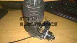
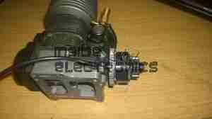
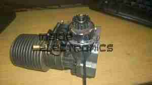
Above is the converted engine with it’s timing sensor. As The installation of this was pretty much standard, a complete strip down of the engine was required to allow the drilling & tapping of the two M3x0.5 holes to mount the sensor bracket to. The front crankshaft bearing has to be drifted out of the crankcase for this to be possible.

Ignition Hall Sensor

Detail of the ignition hall sensor. The bracket has to be modified to allow the sensor to face the magnet in the flywheel. Unlike on an Aero engine, where the magnet would be on the outside edge of the prop driver hub, in this case the hole was drilled in the face of the flywheel near the edge & the magnet pressed in. The Hall sensor is glued to the modified bracket with the leads bent to position the smaller face towards the back of the flywheel.
The clearance from the magnet to sensor is approx. 4mm.

Flywheel Magnet
Flywheel Magnet

Detail of the magnet pressed into the flywheel. A 3.9mm hole was drilled from the back face, approx 2mm from the edge, & the magnet pressed into place with gentle taps from a mallet & drift, as I had no vice to hand.
Initial timing was a little fiddly due to the flywheel only being held on with a nut & tapered sleeve, so a timing mark can be made inside the rear of the crankcase, across the crank throw & case to mark the 28 degree BTDC point, the flywheel is then adjusted to make the ignition fire at this point, before carefully tightening the flywheel retaining nut to ensure no relative movement occurs.
The slots in the sensor bracket allow several degrees of movement to fine adjust the timing point once this rough location has been achieved.

1/4"-32 Spark Plug
1/4″-32 Spark Plug

Definitely the tiniest spark plug I’ve ever seen, about an inch long. Some trouble may be encountered with this on some engines – the electrodes stick out about 2mm further into the combustion chamber than a standard glow plug does. This causes the ground electrode to hit the top of the piston crown. (This happens on the HPI NitroStar 3.5 engine). The addition of another copper washer under the plug before tightening should cure this problem.

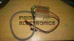
RcExl CDI Ignition Module

Ignition module. Due to the depth of the plug in the heatsink head on these engines, I will have to modify the plug cap to straighten it out, as it will not fit in this configuration.
However, ignition modules are available from HobbyKing with straight plug caps, this makes modification unnecessary

The ignition & components used on this system were obtained from JustEngines.

Posted on Leave a comment

Raspberry Pi Geiger Counter

Geiger Counter Setup

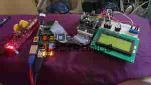
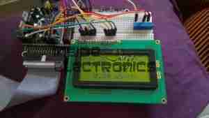
Here’s my latest project with the Pi: interfacing it with the Sparkfun Geiger counter & outputting the resulting data to a character LCD.

The geiger counter is interfaced with it’s USB port, with the random number generator firmware. A Python script reads from the serial port & every minute outputs CPM & µSv/h data to the display.

The Python code is a mash of a few different projects I found online, for different geiger counters & some of my own customisations & code to write the info to the display & convert CPM into µSv/h.

This also writes all the data into a file at /var/log/radlog.txt

The code for this is below:

import time
import sys
import serial
import os
import RPIO
from RPLCD import CharLCD
from subprocess import * 
from datetime import datetime

# configuration settings

logfile = "/var/log/radlog" # location to save log data
serial_port = "/dev/ttyUSB0"
lcd = CharLCD(pin_rs=15, pin_rw=18, pin_e=16, pins_data=[21, 22, 23, 24], numbering_mode=RPIO.BOARD, cols=16, rows=4, dotsize=10) #Init LCD with physical parameters

f = open(logfile,"a")

ser = serial.Serial(serial_port,9600,timeout=1)

one = 0

#Init LCD with initial values.
lcd.cursor_pos = (0, 1)
lcd.write_string("Geiger Counter")
lcd.cursor_pos = (1, 2)
lcd.write_string("Initializing")
lcd.cursor_pos = (2,-3)
lcd.write_string("Please Wait...")
lcd.cursor_pos = (3, 0)
lcd.write_string(str(0) +" uSv/h")
f.write("Geiger Counter Initialized\n")
f.flush()
while 1==1:
  stamp = int(time.time())
  stamp == round(stamp,0)
  stamp = stamp + 60
  count = 0  
  while 1==1:
      ct = int(time.time())
      ct == round(ct,0)
      if ct > stamp:  break
      #Read from serial port
      bit = ser.read(1)
      if bit != "":
          count = count + 1
          #Conversion of counts per minute to uSv/hr
          usvh = count * 0.01
  at = str(time.asctime())
  t = str(time.time())
  #Write line to log file & print info to console
  f.write("["+at+"."+t+"] "+str(count) + " CPM " +str(usvh) + " uSv/h\n")
  f.flush()
  print "["+at+"."+t+"] Count "+str(count) + " " + str(usvh) +" uSv/hr"
  #Send measurement info to LCD
  lcd.clear()
  lcd.cursor_pos = (0, 0)
  lcd.write_string(datetime.now().strftime('%b %d  %H:%M:%S\n'))
  lcd.cursor_pos = (1, 0)
  lcd.write_string("Radiation Level:")
  lcd.cursor_pos = (2, 1)
  lcd.write_string(str(count) +" CPM")
  lcd.cursor_pos = (3, -1)
  lcd.write_string(str(usvh) +" uSv/h")
Info Display
Info Display
Posted on Leave a comment

Site Hosting

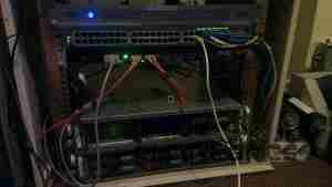
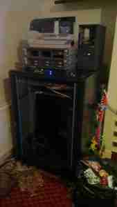
Original Rack
Original Rack

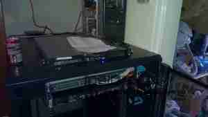
There have been quite a few updates to the hosting solution for this site, which is hosted locally in my house, from the above setup, in a small comms rack, to a new 22U half rack, with some hardware upgrades to come.

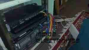
Core Switch Disconnected

Core switch here has been removed, with the rest of the core network equipment. The site was kept online by a direct connection into the gateway to the intertubes.

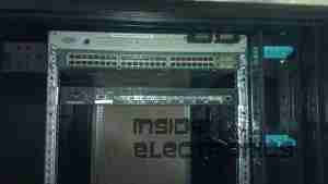
Switching Gear Installed

New 22U rack, with the core switch, FC switch & management & monitoring server installed.

Router Going In
Router Going In

As I had no rack rails to start with, the servers were placed on the top of the rack to start off, here is the Dell PowerEdge 860 pfSense core router installed, with the initial switch wiring to get the internal core network back online. This machine load balances two connections for an aggregated bandwidth of 140MB/s downstream & 15MB/s upstream.
The tower server behind is the NAS unit that runs the backups of the main & auxiliary webservers.

Almost Done
Almost Done

Still with no rack kits, all the servers are placed on top of the rack, before final installation. This allows running of the network before the rest of the equipment was installed.

The main server & aux server are HP ProLiant DL380 G3 servers, with redundant network connections.

Still to arrive are the final rack kits for the servers & a set of HP BL20p Blade servers, which will be running the sites in the future.

Stay tuned for more updates as they happen!

Posted on 1 Comment

Co-Op Bank Card Reader

Keypad
Keypad

This is a little security measure you get with Internet Banking with the Co-Op, generates codes to confirm your identity using your bank card. About the size of a pocket calculator, this is the keypad & screen.

Card Slot
Card Slot

The rear of the unit, the card slots into the top, manufactured by Gemalto Digital Security.

Card Contacts
Card Contacts

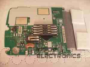
Outer back cover removed, showing the 8 contacts for the chip on the bank card, the 2 contacts below that switch on power when a card is inserted. Power comes from 2 lithium coin cells in the compartment on the lower left.

PCB Rear
PCB Rear

PCB removed from the casing, showing the internal components. Two large pads at top left are battery connections, while the only IC on the board is the main CPU, under the card connector. 6MHz oscillator & 32Khz crystal on board for processing & timekeeping. LCD screen connection at far right.

Keypad Contacts
Keypad Contacts

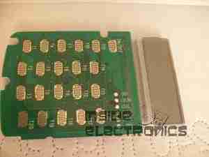
Reverse side of the PCB, with the keypad contacts. LCD on right, with programming interface pads at side of keypad.