My new DMM I posted about a while back came with PC software & drivers for the RS-232 interface, on a CD. I haven’t used CDs for some time, so I had to dig out my USB drive.
The Tenma website doesn’t list the software for all their models, so to help others I’m posting an archive of all the supplied drivers here. The archive contains software & drivers for the following Tenma models:
Now the controllers have arrived, I can rejig the supplies to have proper thermal control on their cooling.
Changes Overview
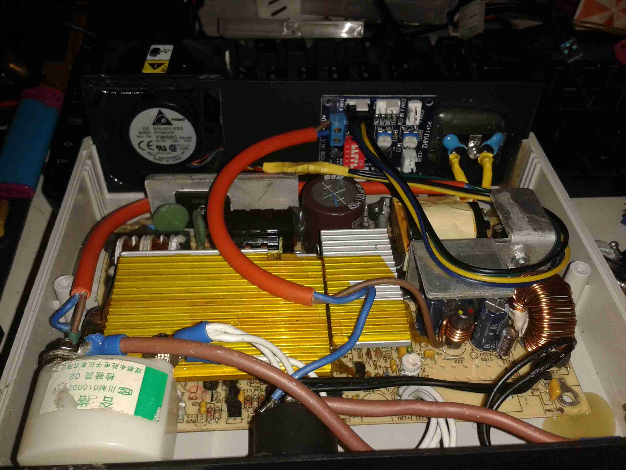
Here’s the top off the PSU. The board has been added to the back panel, getting it’s 12v supply from the cable that originally fed the fan directly. Luckily there was just enough length on the temperature probe to fit it to the output rectifier heatsink without modification.
To connect to the standard 4-pin headers on the controller, I’ve spliced on a PC fan extension cable, as these fans spent their previous lives in servers, with odd custom connectors.
Fan Controller
Here’s the controller itself, the temperature probe is inserted between the main transformer & the rectifier heatsink.
I’ve set the controller to start accelerating the fan at 50°C, with full speed at 70°C.
Full Load Test
Under a full load test for 1 hour, the fan didn’t even speed up past about 40% of full power. The very high airflow from these fans is doing an excellent job of keeping the supply cool. Previously the entire case was very hot to the touch, now everything is cool & just a hint of warm air exits the vents. As the fan never runs at full speed, the noise isn’t too deafening, and immediately spools back down to minimum power when the load is removed.
To cap off the series of scripts for doing easy timelapse video on the Raspberry Pi, here’s a script to generate a H.264 video from the images.
[snippet id=”1771″]
This should be run on a powerful PC rather than the Pi – generating video on the Pi itself is likely to be very slow indeed.
I have also done a quick update to the timelapse generator script to generate images of the correct size. This helps save disk space & the video generation doesn’t have to resize the images first, saving CPU cycles.
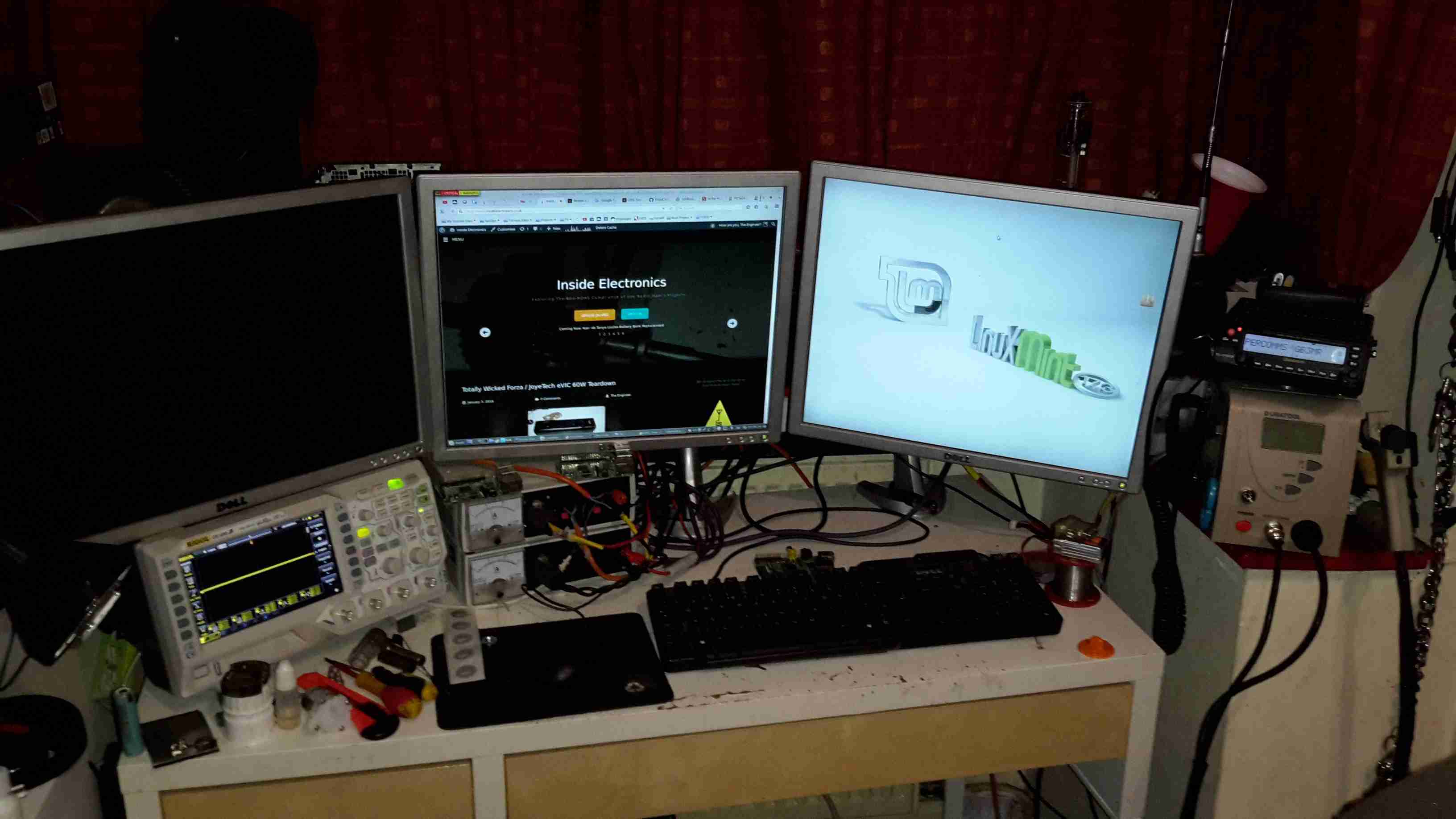
Main radio of course is housed on the left, it’s partially hidden under my currently over-populated breadboard.
All 3 monitors are linked to the same PC, using a pair of video cards. This is a very flexible system with so much screen real estate.
Main system power is provided by the pair of power supplies next to the radio – these are homebrew units using surplus switched mode PSU boards. Check my previous posts for more details.
Power Supplies
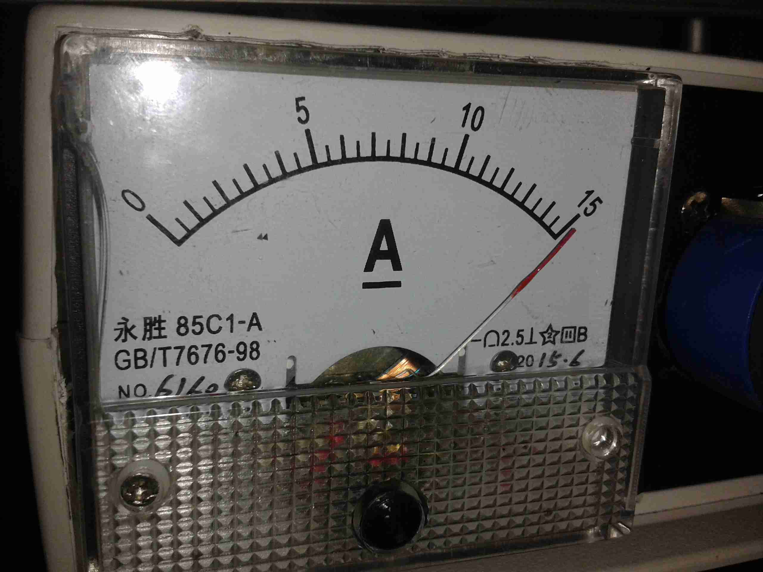
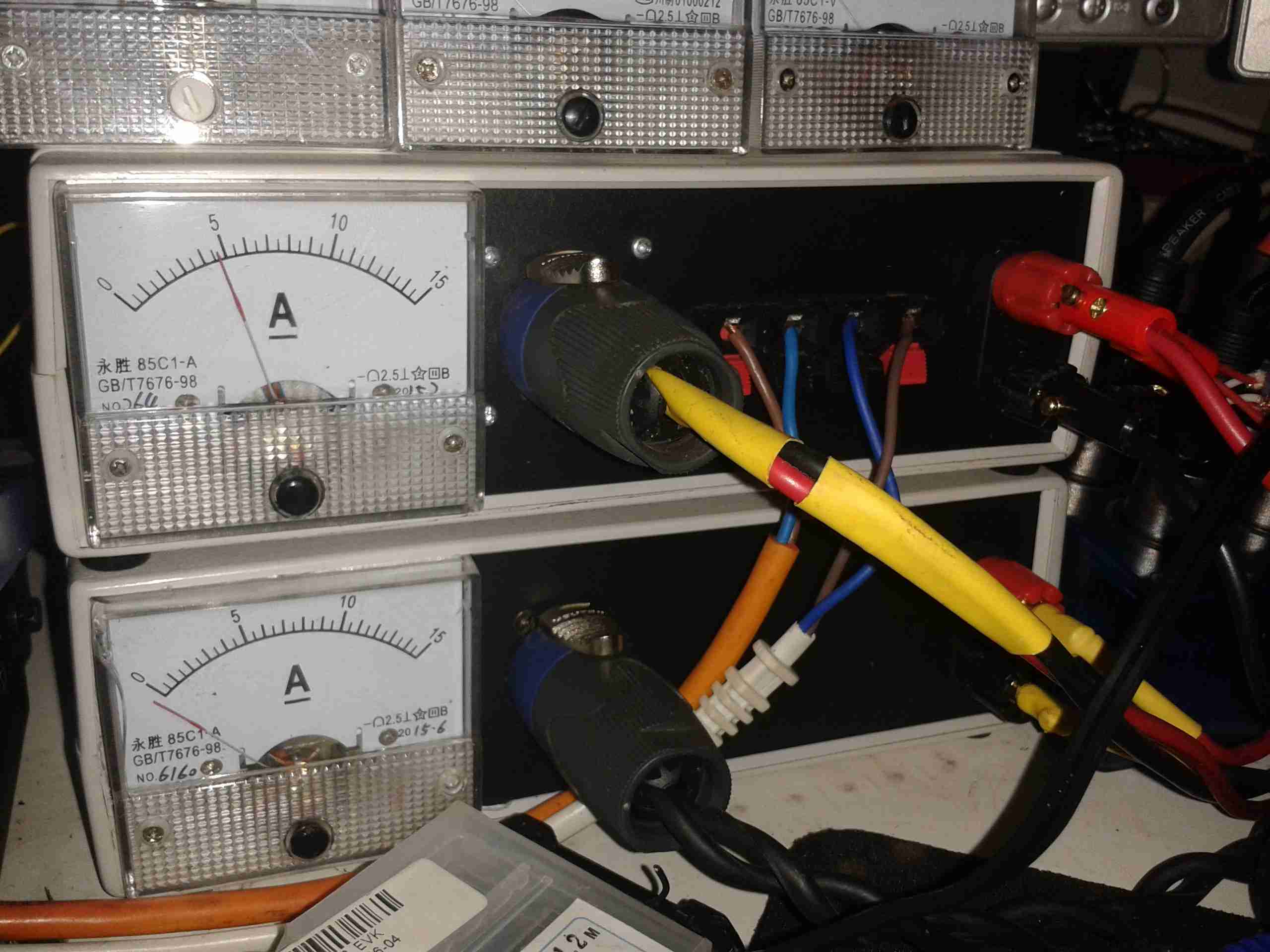
The mainpowersupply system. These two supplies are cross connected, giving a total DC amperage of 30A at 13.8v. There is also a link to a large 220Ah lead-acid battery bank (orange cable), to keep me on the air during power outages. This cable is getting upgraded to something more beefy shortly. The white cable is currently supplying power to my onlineradiation monitor.
The main high-currentDC outputs are the Speakon connectors next to the meters. The top one is powering the radio directly, the bottom is linked through to my 12v distribution box for lower current loads, such as the oscilloscope, audio amplifiers, tools, etc.
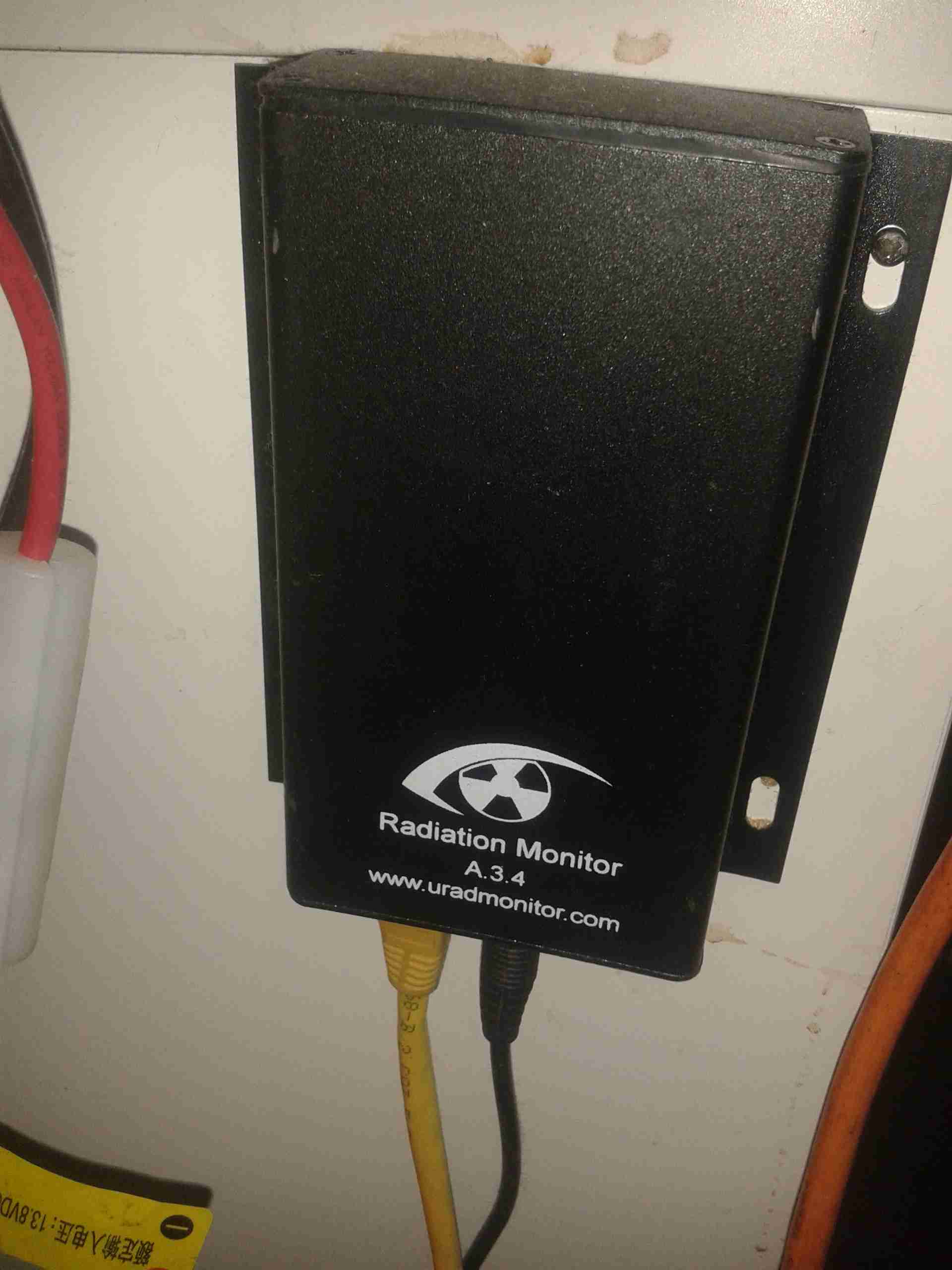
Radiation Monitor
Attached to the side of the desk is the radiation monitor itself.
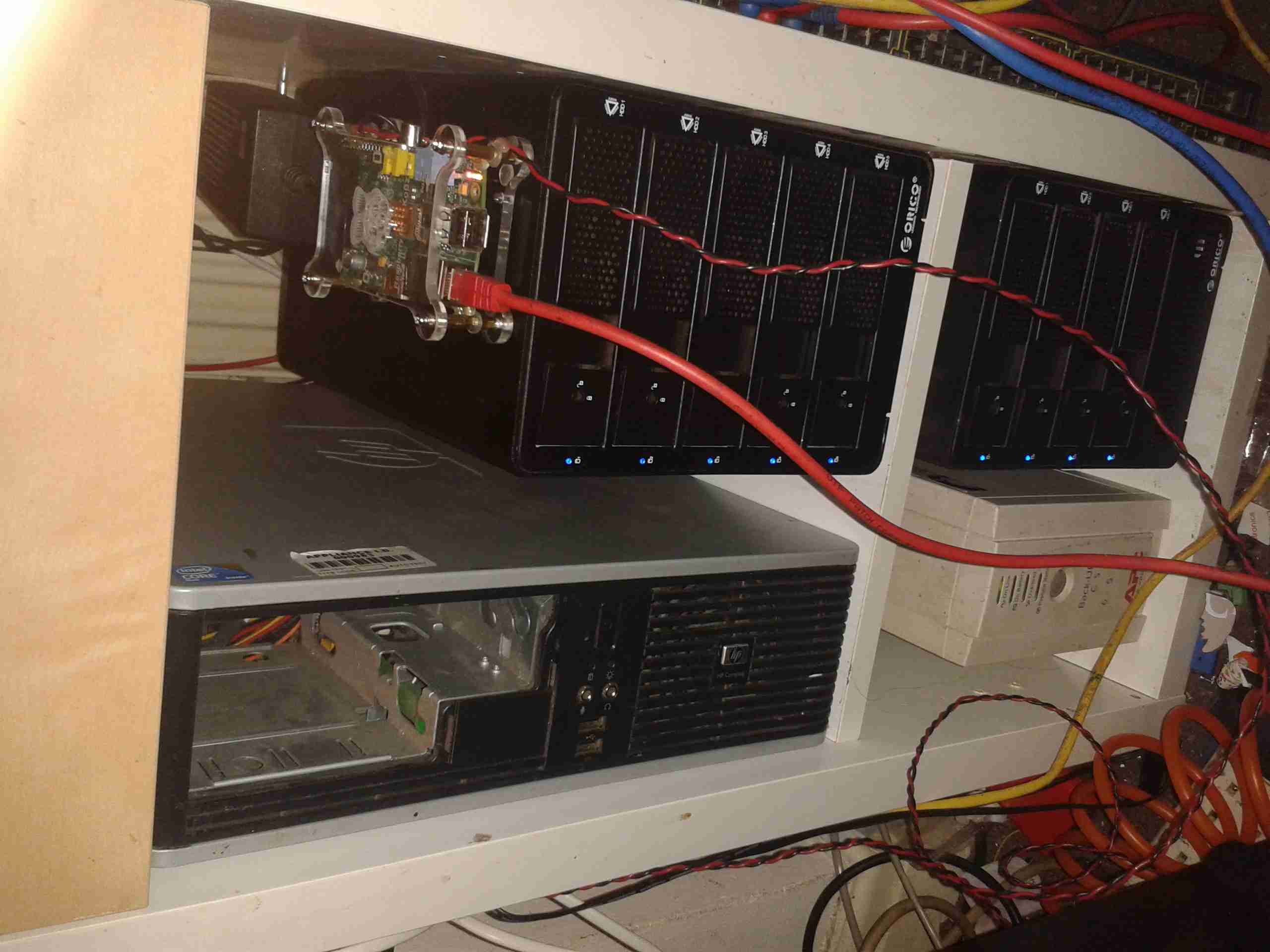
Core NAS
Under the radio is the core NAS of the network. It’s an array of 9 4TB disks, in RAID6, giving a total capacity after parity of 28TB. This provides storage & services to every other machine in the shack, the Raspberry Pi on top of the disk array is doing general network housekeeping & monitoring, also generating the graphs for the Radiation Monitor page. A Cisco 48-portswitch is partially out of frame on the right, providing 100MB Ethernet to the devices that don’t require gigabit.
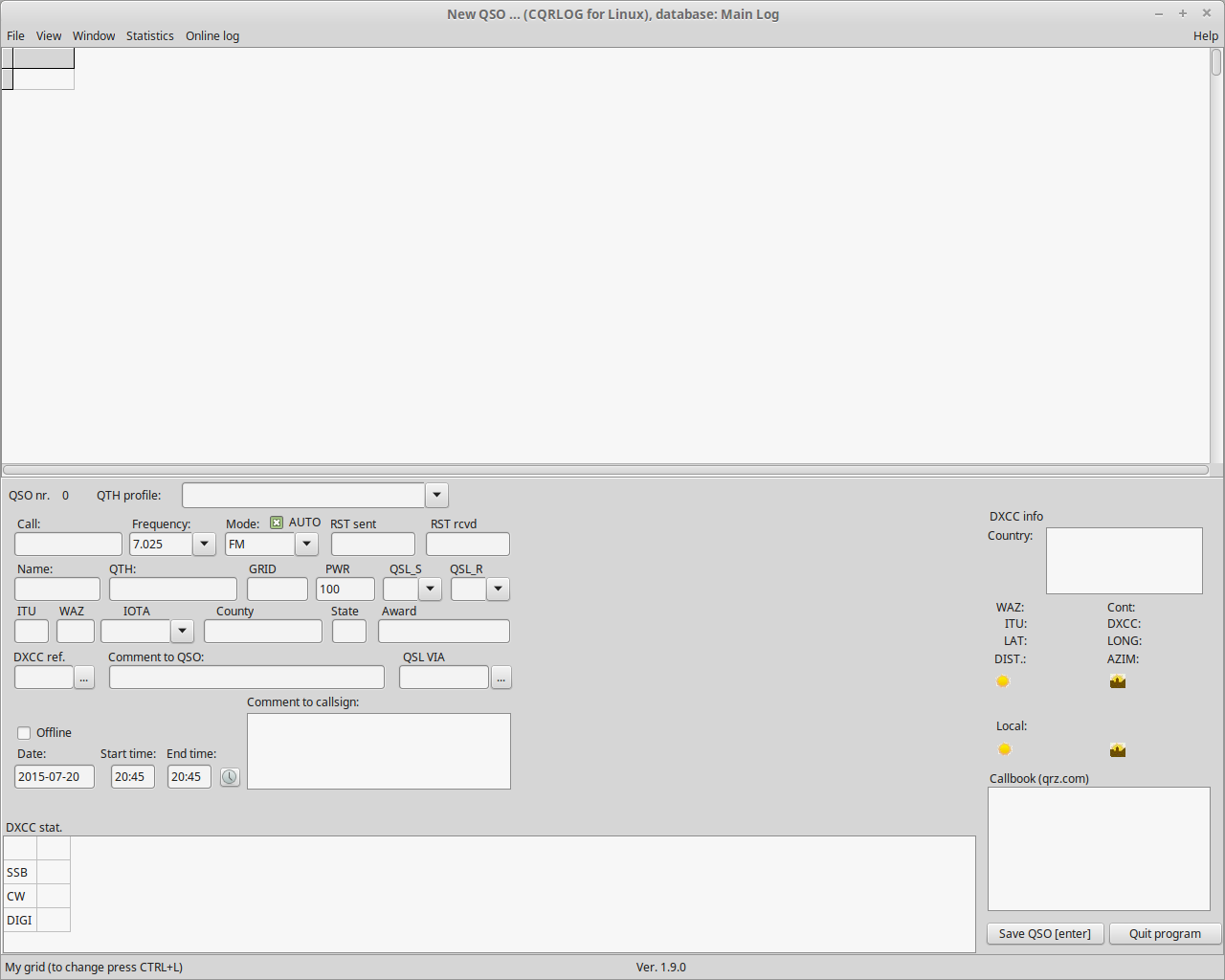
As per my site update post, I have migrated my radio log onto a new system, from CQRLOG.
CQR log has served me well since I first started in Amateur Radio, however it’s a bit complex to use, requires a backend MySQL server for it’s database, and as it’s a local application, it’s not possible to share my log with other Hams without some difficulty.
The only other major system with an online logging system is QRZ, and I find that particular site a bit of a pain, and many of the features there aren’t free. (Although it’s not horrendously expensive, I’m on a very tight budget & I must save where I can).
CQRLOG Screenshot
Because of these points, I went on a search for something that would better serve my needs. I have discovered during this search that there’s liitle out there in the self-hosted respect.
I did however find Cloudlog, a web based logging system in PHP & MySQL.
This new system allows integration with the main site, as I can run it on the same server & LAMP stack, it’s very simple to use, is visually pleasing and it even generates a Google Map view of recent QSO locations.
It will also allow me to save some resources on my main PC, running a full-blown MySQL server in the background just for a single application is resource intensive, and a bit of a waste of CPU cycles. (CQRLOG and it’s associated MySQL server is 300MB of disk space, CloudLog is 27MB).
Backups are made simpler with this system also, as it’s running on my core systems, incremental backups are taken every 3 hours, with a full system backup every 24 hours. Combined with offsite backup sync, data loss is very unlikely in any event. All this is completely automatic.
I can also take an ADIF file from Cloudlog for use with any other logging application, if the need arises.
Cloudlog is built & maintained by Peter Goodhall, 2E0SQL.
From the looks of Github, there’s also a version 2 in development, although now I have version 1 up & running, I might just stick with it, unless an easy upgrade path is available.
When I am not operating mobile, new QSOs should appear in this system almost immediately, with their respective pins on the map. (These are generated by the Grid Square location, so accuracy may vary).
If you’ve spoken to me on the air & I haven’t updated it, I’m most likely away from an internet connection, in which case your callsign will appear as soon as I have access.
This unit was bought from eBay to experiment with Magnetic Stripe cards, for little money. This unit is capable of reading & writing all 3 tracks, & both Hi-Co & Lo-Co card types.
Interfaced to a PC through USB, this has a built in PL2303 USB-Serial IC & requires 3A at 9v DC to operate.
The 3 Indicator LEDs on the top of the unit can be toggled by the included software for Power/OK/Fault condition signalling.
Unit Bottom
Bottom of the unit with the model labels.
Model Label
Closeup of the model label & serial number.
PCB Bottom
Here the bottom cover has been removed, showing the main PCB. The pair of large ICs bottom center interface with the magnetic heads. The IC above them has had the markings sanded off.
USB-Serial Interface
Closeup of the Prolific PL-2303 USB-Serial converter IC.
PCB Top
Here the connections to the R/W heads are visible, current limiting resistors at the left for the write head, a pair of signal relays, a pair of optoisolators & a LM7805 linear voltage regulator.
LEDs
Here is the trio of indicator LEDs on a small sub-board.
Frame Bottom
The PCB has been removed from the main frame here, the only component visible is the rotary encoder.
Rotary Encoder
The rotary encoder has a rubber wheel fitted, which reads the speed of the card as it is being swiped for writing. This allows the control logic to write the data to the stripe at the correct rate for the speed of the card. This allows the unit to write cards from 5-50 inches per second speed.
The Write head is directly behind the rubber pressure roller.
Read/Write Heads
Here you can see the R/W head assembly. The write head is on the right, read on the left. When a card is written to, it immediately gets read by the second head for verification.
Top removed from the mouse, the ball fits in the gap in the centre. The slotted discs are visible which contact the ball & move relative to the surface the mouse is on.
PCB
PCB removed from the shell. Pairs of IR LEDs & Phototransistors make rotary encoders with the slotted discs. The microswitches read the mouse buttons & wheel.
IC in the centre interfaces with the PC over a PS/2 connection.
Tip Jar
If you’ve found my content useful, please consider leaving a donation by clicking the Tip Jar below!
All collected funds go towards new content & the costs of keeping the server online.