To cap off the series of scripts for doing easy timelapse video on the Raspberry Pi, here’s a script to generate a H.264 video from the images.
[snippet id=”1771″]
This should be run on a powerful PC rather than the Pi – generating video on the Pi itself is likely to be very slow indeed.
I have also done a quick update to the timelapse generator script to generate images of the correct size. This helps save disk space & the video generation doesn’t have to resize the images first, saving CPU cycles.
Here’s a quick look at a Sainsmart frequency counter module. These are useful little gadgets, showing the locked frequency on a small LCD display.
It’s built around an ATMega328 microcontroller (µC), and an MB501L Prescaler IC. The circuit for this is very simple, and is easily traced out from the board.
Frequency Counter
Here’s the back of the board, with the µC on the left & the prescaler IC on the right. This uses a rather novel method for calibration, which is the trimmer capacitor next to the crystal. This trimmer varies the frequency of the µC’s oscillator, affecting the calibration.
Input protection is provided by a pair of 1N4148 diodes in inverse parallel. These will clamp the input to +/-1v.
The prescaler IC is set to 1/64 divide ratio. This means that for an input frequency of 433MHz, it will output a frequency of 6.765625MHz to the µC.
The software in the µC will then calculate the input frequency from this intermediate frequency. This is done because the ATMega controllers aren’t very cabable of measuring such high frequencies.
The calculated frequency is then displayed on the LCD. This is a standard HD44780 display module.
LCD
Power is provided by a 9v PP3 battery, which is then regulated down by a standard LM7805 linear regulator.
Readout
I’ve found it’s not very accurate at all at the lower frequencies, when I fed it 40MHz from a signal generator it displayed a frequency of around 74MHz. This is probably due to the prescaler & the software not being configured for such a low input. In the case for 40MHz input the scaled frequency would have been 625kHz.
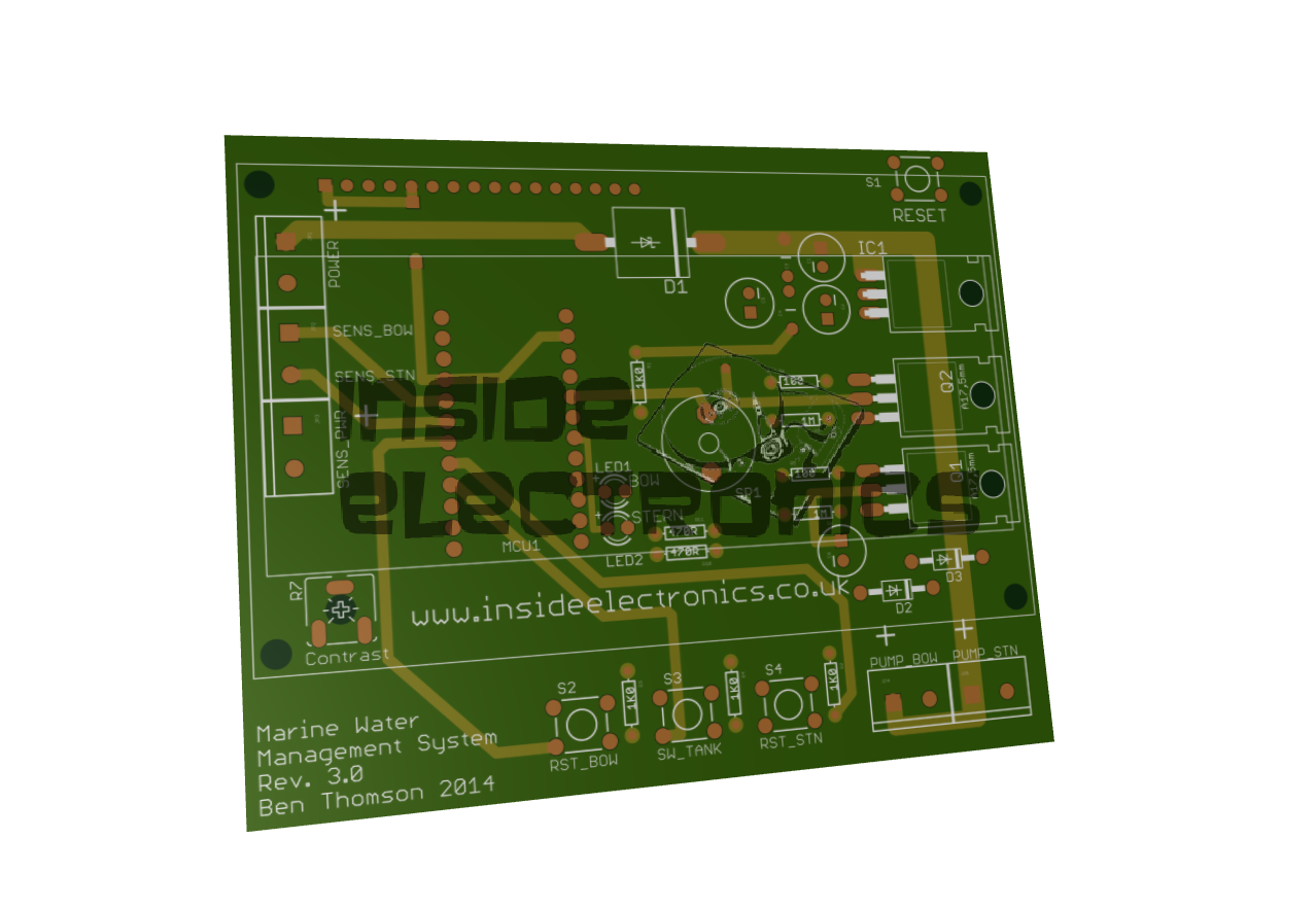
OK, a few revisions have been made to the water management PCB, mainly to reduce the possibility of the brushed DC motors in the water pumps from causing the MCU to crash, with the other changes to the I/O connector positioning & finally upgrading the reverse blocking diode to a 10A capable version rather than 5A.
While sourcing the main propulsion hydraulic system for nb Tanya Louise in the summer, we thought that it would be convenient to have an on board generator that didn’t require dragging off the boat & highly explosive petrol to operate.
As the hydraulics were already being fitted, we decided to add a hydraulically driven generator to solve this issue.
And this is where the problems began…
We were referred to Mike Webb of hydraulicgenerators.co.uk to supply the equipment required for this part of the project, this was to include the alternator itself, hydraulic motor to drive the alternator, the required adaptor plates to mate the motor to the generator head & a control valve block to regulate the oil flow & pressure to the motor.
After a phone call to Mike on 16-07-2013 to discuss our requirements, we settled on a system. I received the following E-Mail the next day from Mike:
Good morning, reference our conversation, Martin from BSP has given me details as to what he will be supplying, on that basis and in light of the special price I have offered, this is what I propose to supply,
1 off New 8kVa – 7kW Hydraulic driven generator 220v single phase 50hz c/w flow control valve, pressure relief valve and on/off solenoid valve, Martin did say that the engine idle is between 1000 and 1200 rpm and max speed is 3600 rpm, valves will be rated accordingly. I have the alternator and parts available now, in order for me to be able to offer this at a significantly discounted price of £ 1.200.00 nett, I will need to utilise the components I have in stock now, so I will need payment asap, delivery will be approx. 7 days, primarily due to the fact that the coupling is fabricated to suit, I can either deliver the unit to you when ready or BSP or hold onto it until everything else is in place. The alternator is a Meccalte S20W that I bought for another customer a few weeks ago, but he cancelled and I don’t have, at this time, anyone else interested in it, so either I do a deal with you at the above price or wait until someone else comes along and wants the unit.
With regards to installation, let me know if you need any help, but it would be best to install when the engine is being installed and the rest of the system hosed up, I assume BSP will be sorting this, in which case I’ll liase with Martin.
I trust that this meets with your approval and look forward to hearing from you.
At this point an order was placed with Mike, & the money transferred so he could begin building the unit for us. As can be seen from the E-Mail, a lead time of 7 days was stated.
After a few phone calls over the following month, firstly being told that the custom parts to mate the generator to the motor had not come back from the engineers, I sent another E-Mail to Mike on 10-09-2013, and got no reply.
Following another phone call, I was told that the generator had been shipped, however Mike would not give me any tracking details for the shipment, and would not initially tell me who it was shipped with.
Again the generator didn’t turn up.
More phone calls ensued & I was told at this point that the shipping company had been confused by the address given, shipped back to Mike. At this point I was informed that the shipping company had actually LOST it. Several more phone calls later I was promised that a replacement generator would now ship no later than 08-10-2013. A follow up E-Mail two days later also generated no reply.
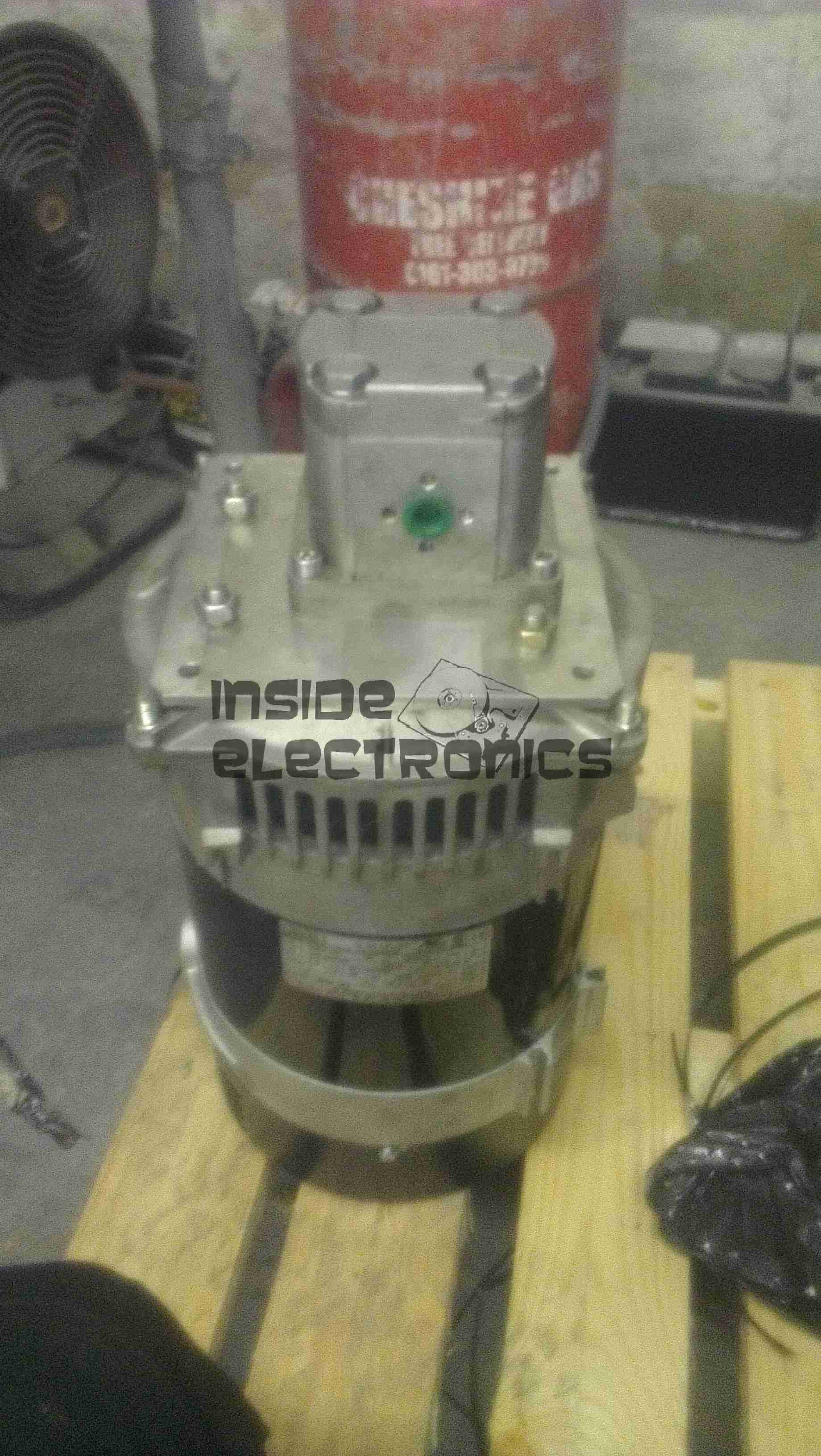
At this point I was beginning to wonder if I would ever see the goods we had paid for, but finally a shipment arrived from Mike
~15-10-2013, over TWO MONTHSafter our promised delivery date. However, even having been delivered, all was not well with the goods.
Generator Pallet
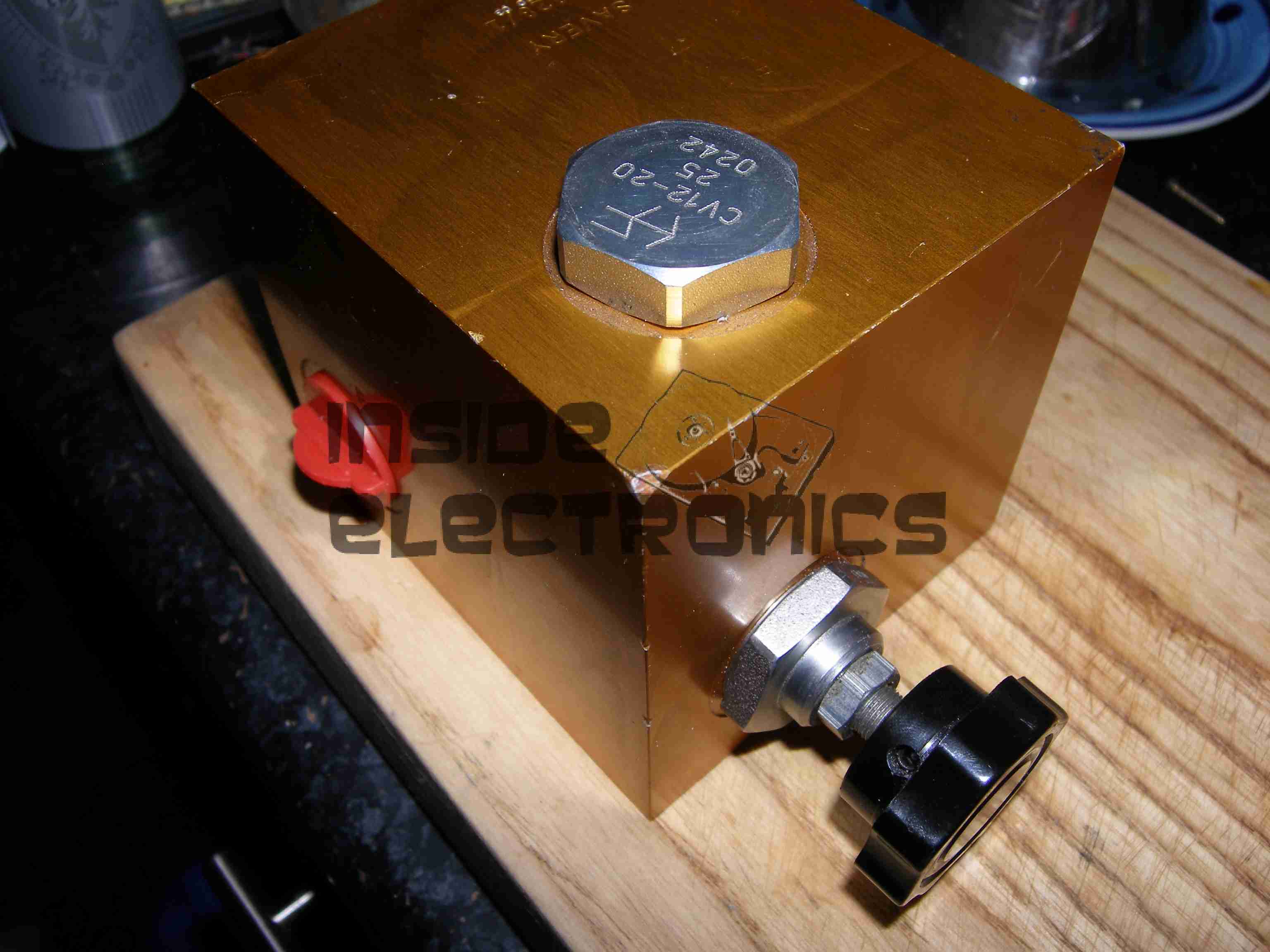
Above is the generator supplied. No mounting bracket, no integrated valve block, in short, nothing like what was described in Mike’s documentation & website. The original documentation is available here for reference: [download id=”5564″]
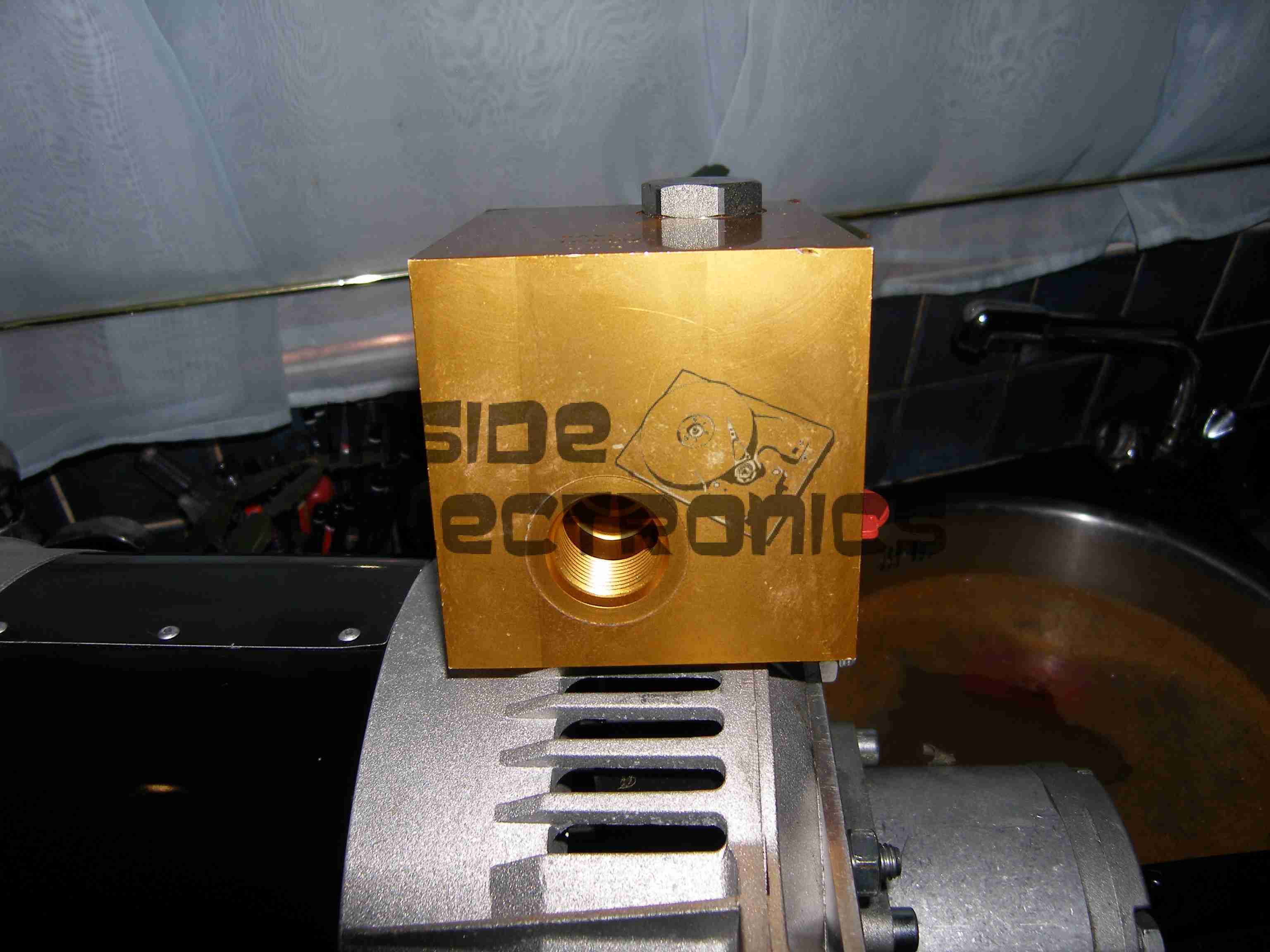
As can be seen, there is an open port on the side of the valve block. This is where the ON/OFF control solenoid valve is supposed to be located.
After several more unanswered E-Mails & phone calls, I had to get somewhat more forceful in my messages, as now Mike had begun outright lying about what was specified in the original order. In which that there was no solenoid valve required. So the following E-Mail was sent 21-10-2013:
Mike,
Having had a conversation with Martin, about him attempting to contact you regarding what you have supplied to us, I need this resolving ASAP now, as I am being held up by the fact that there is an open port on your valve block where the solenoid control valve is supposed to be located.
As it stands the valve block & therefore the generator you have supplied to us is useless for it’s intended purpose & I will be seeking legal advice on this matter if a resolution cannot be made this week, considering you have not replied to any E-Mail I have sent since the unit’s massively delayed arrived.
In your original correspondence it is certainly indicated that this valve was to be fitted, which was also Martin’s instruction to you.
I await your expedient response.
This threat of legal action actually spurred a response from Mike, who finally replied with the following on 25-10-2013:
Ben,
Sorry about all this, I have been away and down with a bug for the last week, I will sort this today and will have the required parts shipped to you on Monday for Tuesday delivery.
Regards
Mike
Another promise of a delivery date, so I waited a little longer, until the Friday of that week. Still no delivery. No surprise there then.
(I didn’t believe the story about illness either).
At this point I again attempted contact, but got nowhere, even with legal threats. So I’ve given up completely on this & been forced to source the parts elsewhere at extra cost.
This company is not the one to go to if you require a hydraulic generator unit for any application, as you’d be lucky to get any part of what you order on time, if at all.
Operations are run by an all out liar who seems to be happy to accept money but not ship the goods that had been paid for.
Mike having explained to me that the shipping company had lost a generator, and he would have to build me another one to replace it also does not make sense, as in the initial phone call & mail he stated that the Meccalte generator that we eventually received was a single unit that was specially ordered for another client, and the factory build date on the unit certainly gave away the fact that the generator head had been sat around for some considerable time before I came along & made a purchase.
Hopefully this post will get a high Google ranking, to ensure that anyone else who happens to be looking for a similar piece of equipment does not have the misfortune to trust this man.
We were referred to him on good faith & unfortunately in this case it did not go well.
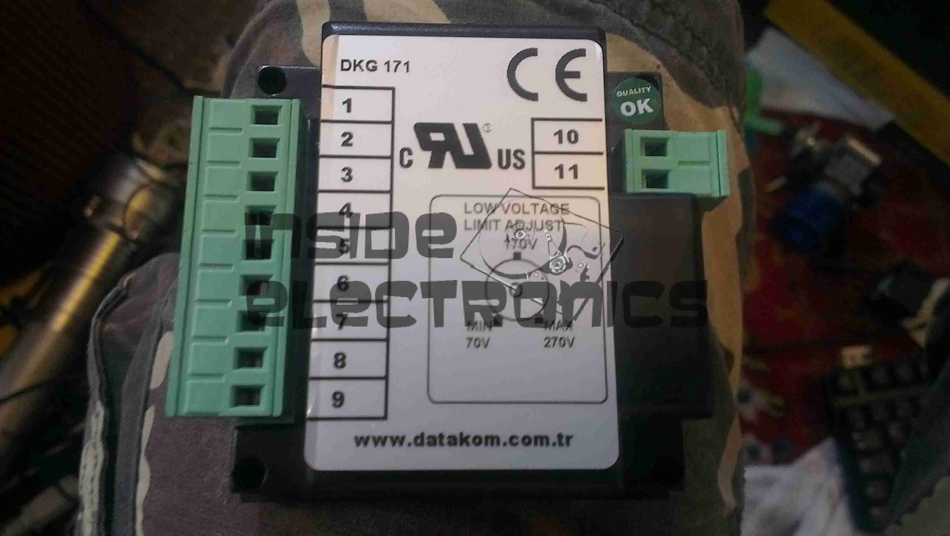
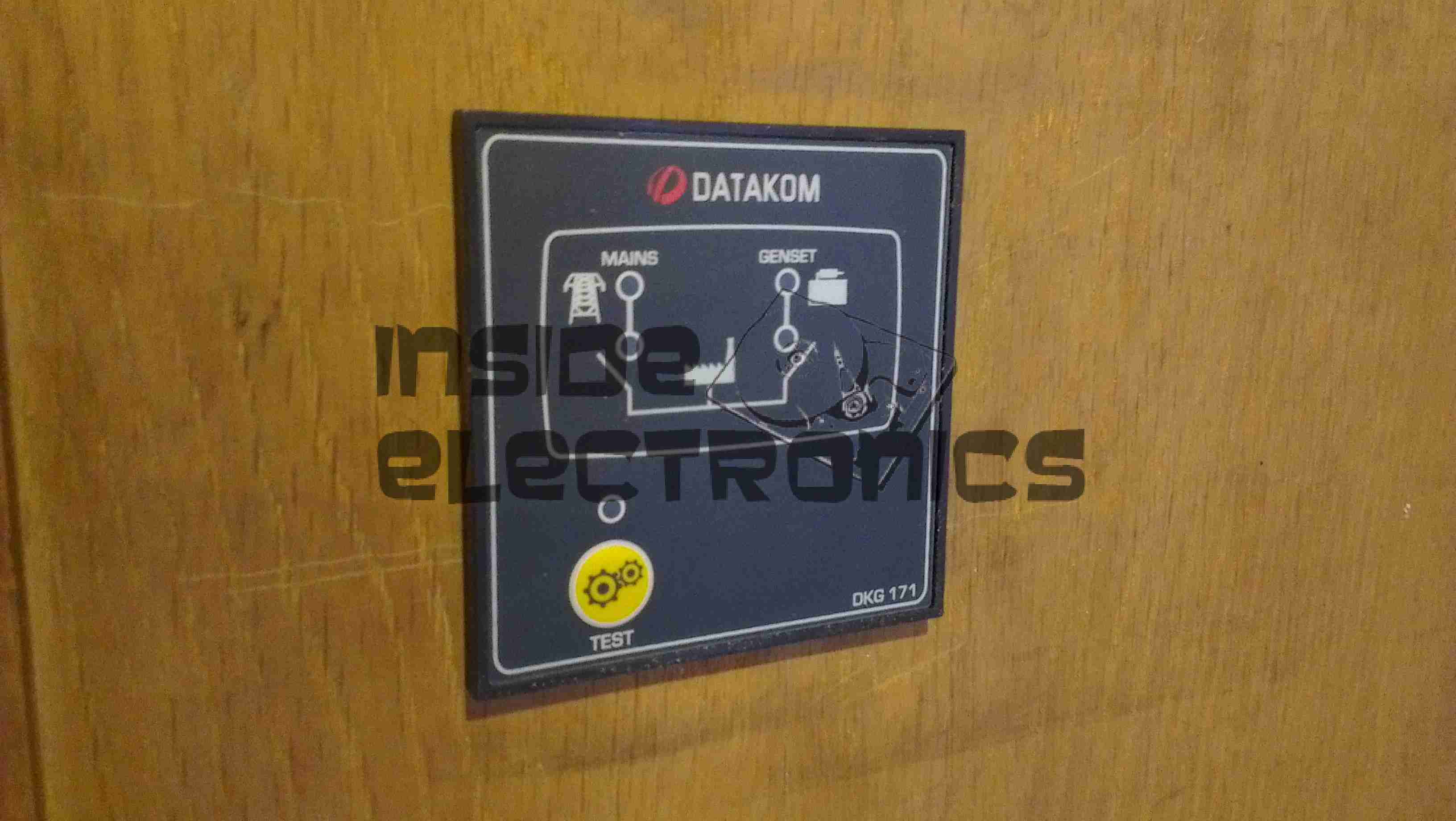
Here is a teardown of the Datakom DKG-171 generator transfer controller. Here is the front of the unit, with the pictogram of the system, the indicator LEDs & the generator test button.
Rear
The rear of the unit features the connection points for the mains, generator & generator control I/O.
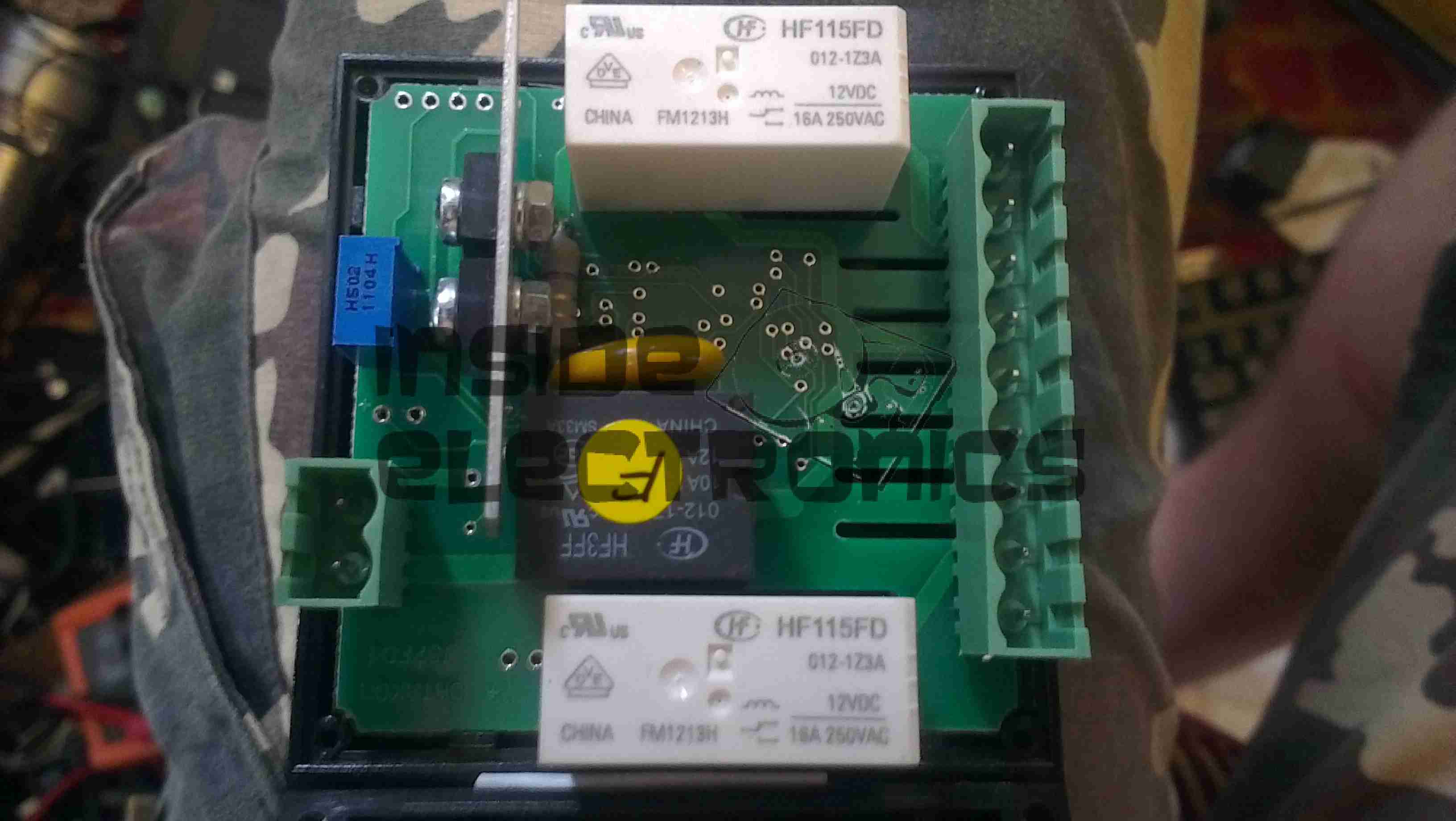
PCB Rear
Rear of the PCB with the control relays. The two larger relays switch in the remote contactors to switch the mains supply over between the grid & the generator, while the smaller relay switches 12v power out to a terminal to automatically start the generator.
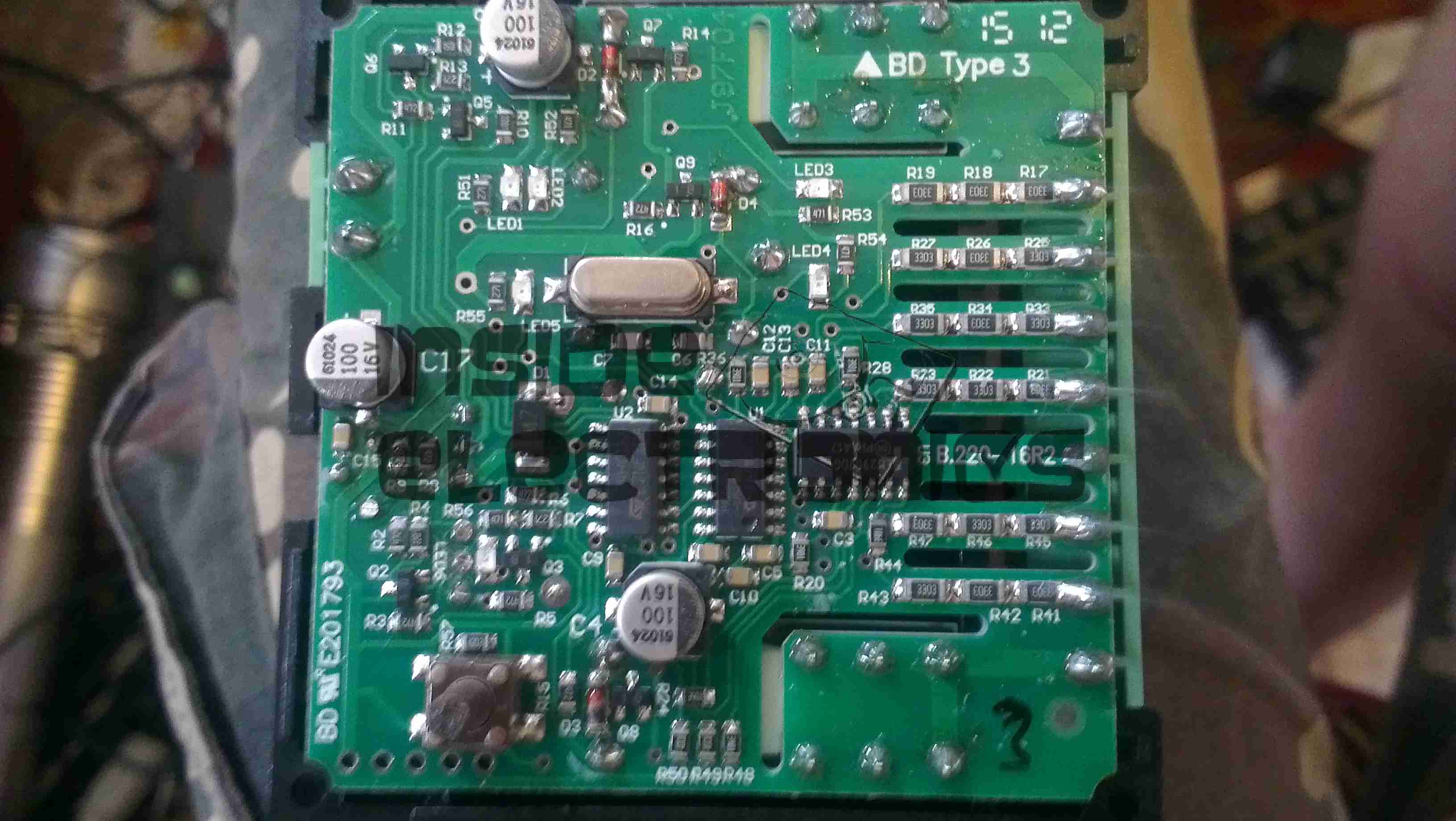
PCB Front
Front of the PCB with the control logic & main PIC microcontroller.
Here is the latest build & addition to the boat, in preparation for delivery of an 8kVa hydraulically driven generator unit – an automatic transfer switch.
Above can be seen the completed contactor unit, mounted in the engine bay.
This unit takes feeders from both the shore power socket & the generator unit & switches them independently through to the domestic 240v AC systems on board.
Contactor switching is done by a Datakom DKG-171 automatic generator controller.
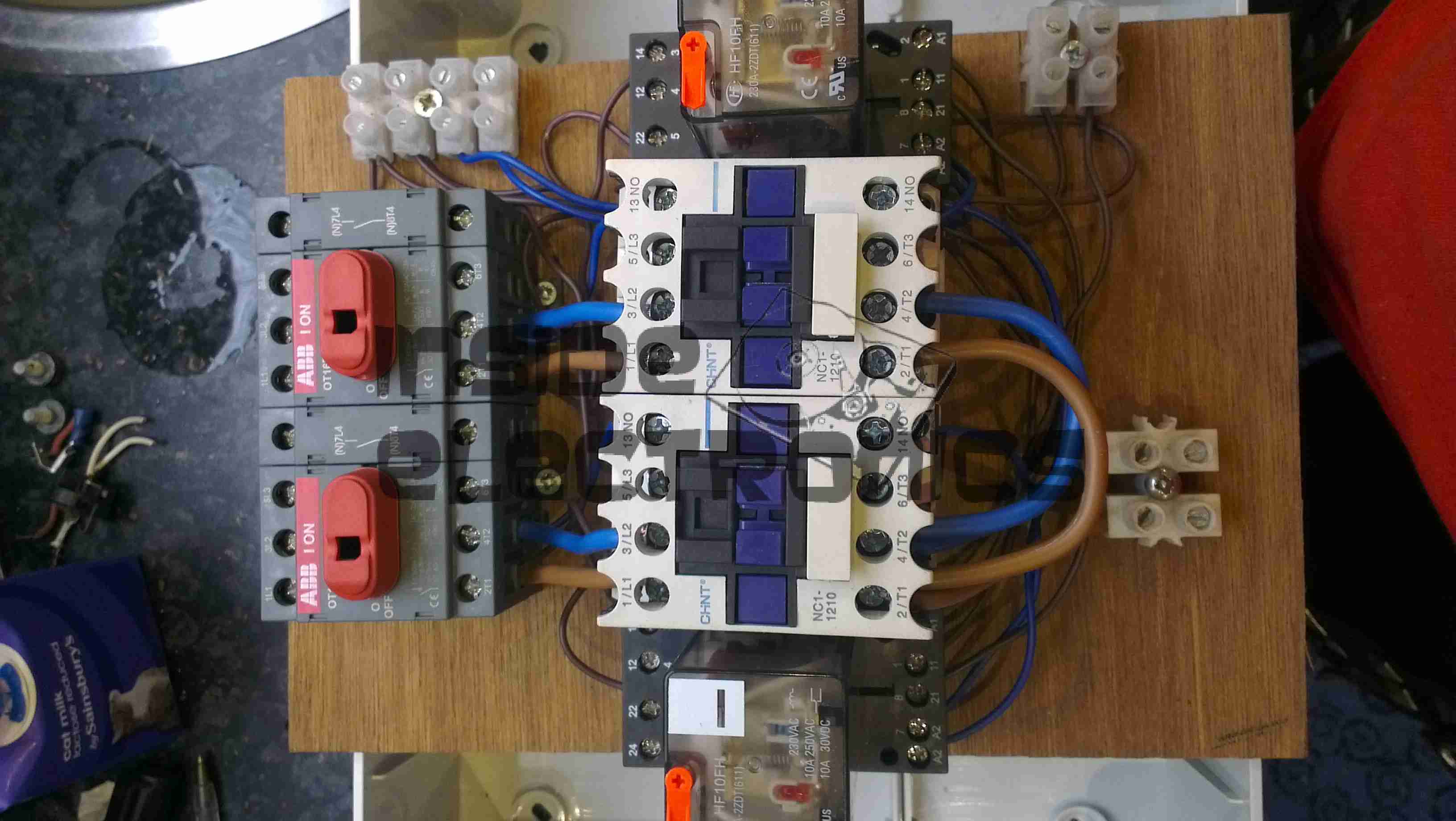
Switching Unit
Here are the contactors & isolators, before fitting to the wallbox. Power comes in one the left, through the large 25A isolating switches, before feeding to a pair of 30A contactors. The pair of outer relays next to the contactors are interlocks. These ensure that when one contactor is energized, the other is electrically locked out. Even if the interlock relay is manually operated with the orange flag visible on the top of the unit, they are wired to de-energize both contactors. This ensures that under no circumstances can both power sources be connected at the same time.
Panel Cutout
The generator controller requires a 68mmx68mm panel cutout for mounting. This was done in the main panel next to the electrical locker.
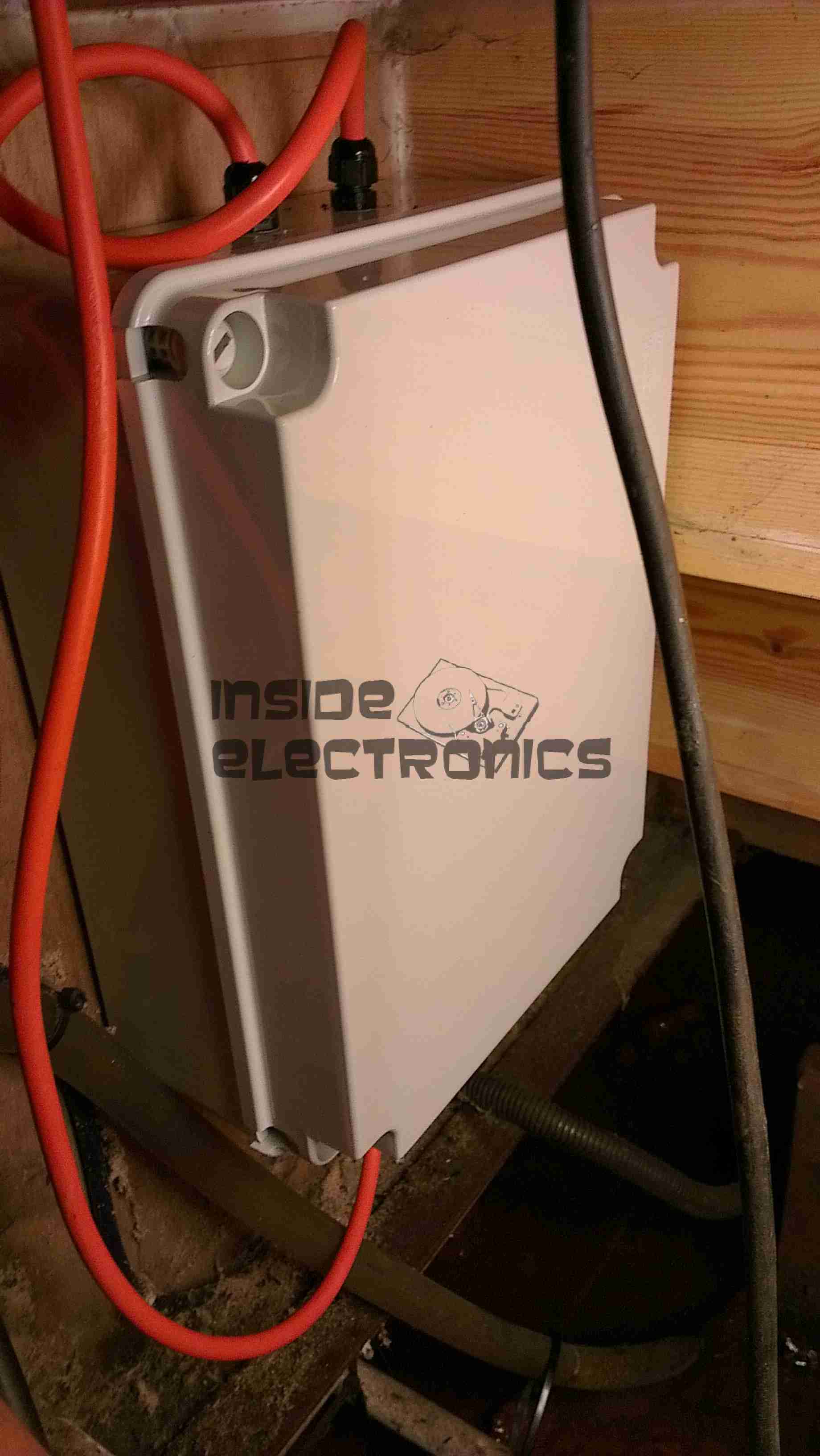
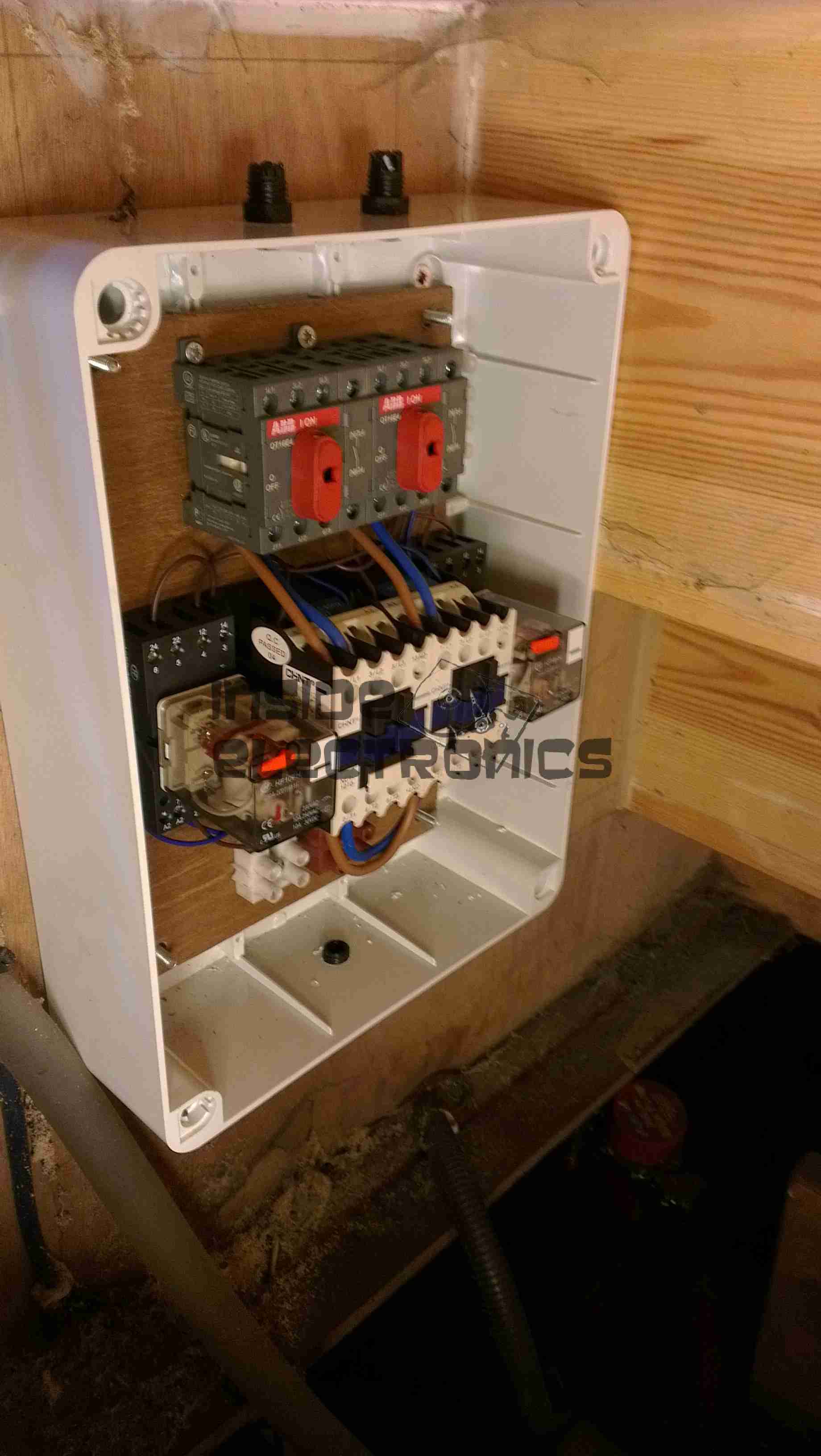
Box Fitted
Here the contactor board has been fitted into the wallbox & the cable glands fitted before wiring.
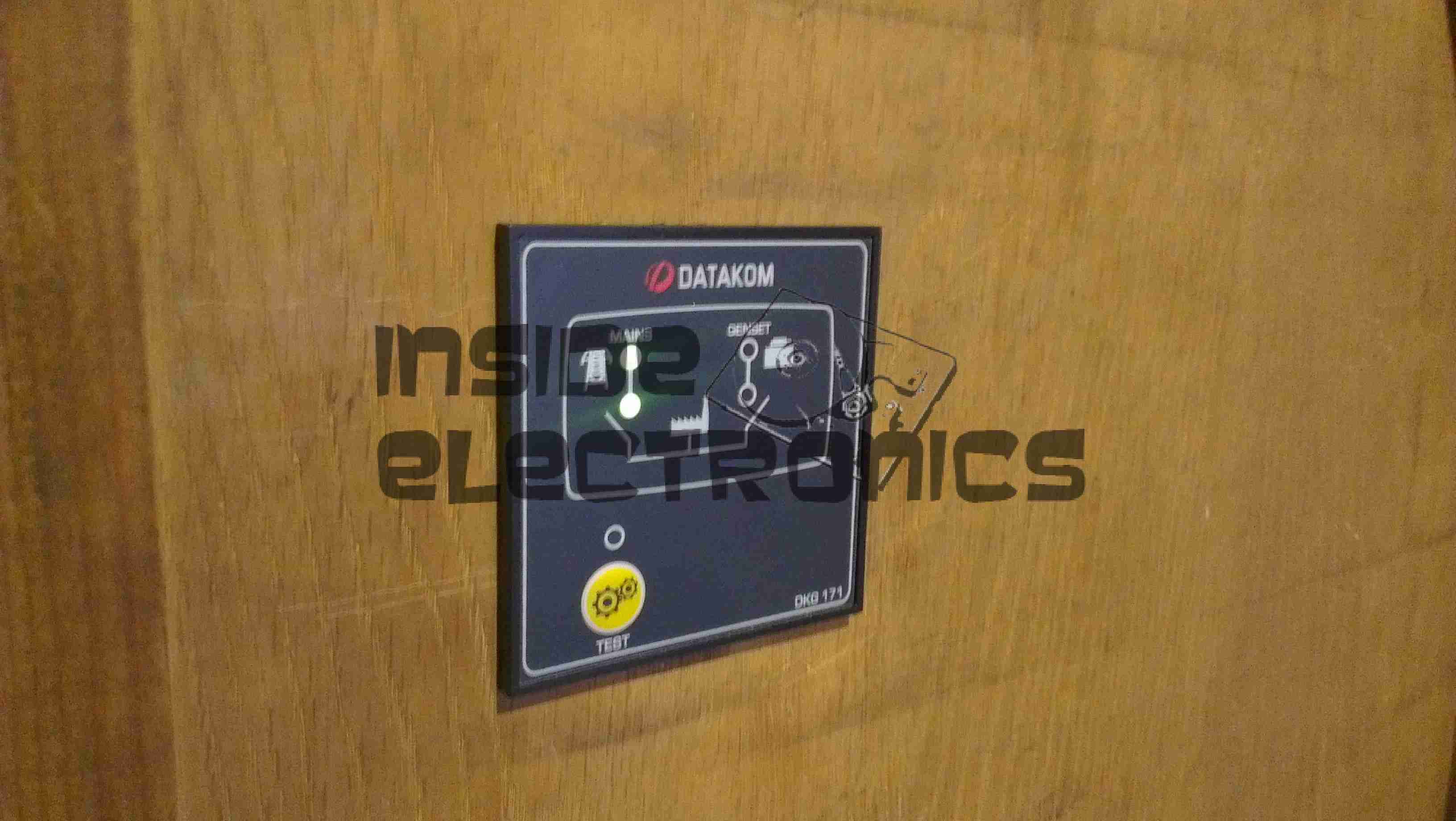
DKG-171System Online
The generator controller fitted & finally energized. The indicator LEDs on the front of the unit let the user know where power is currently being supplied from & which contactor is energized.
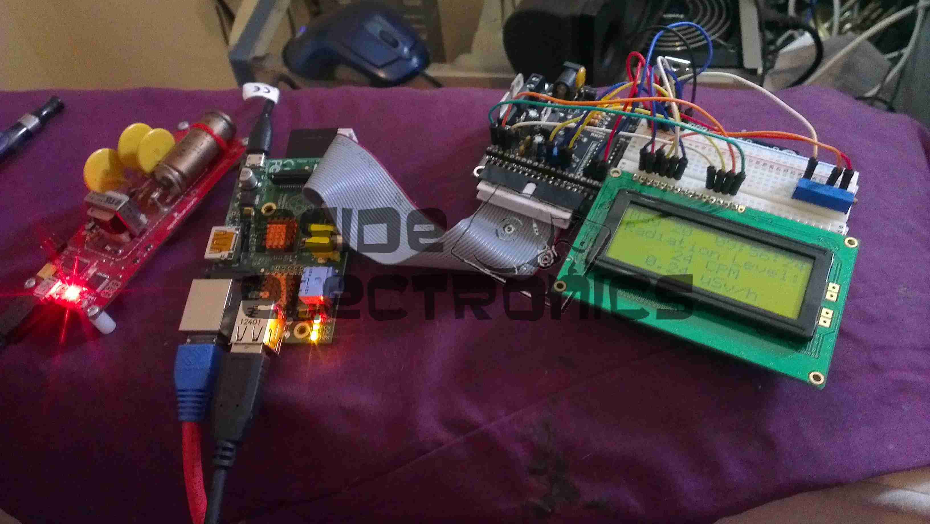
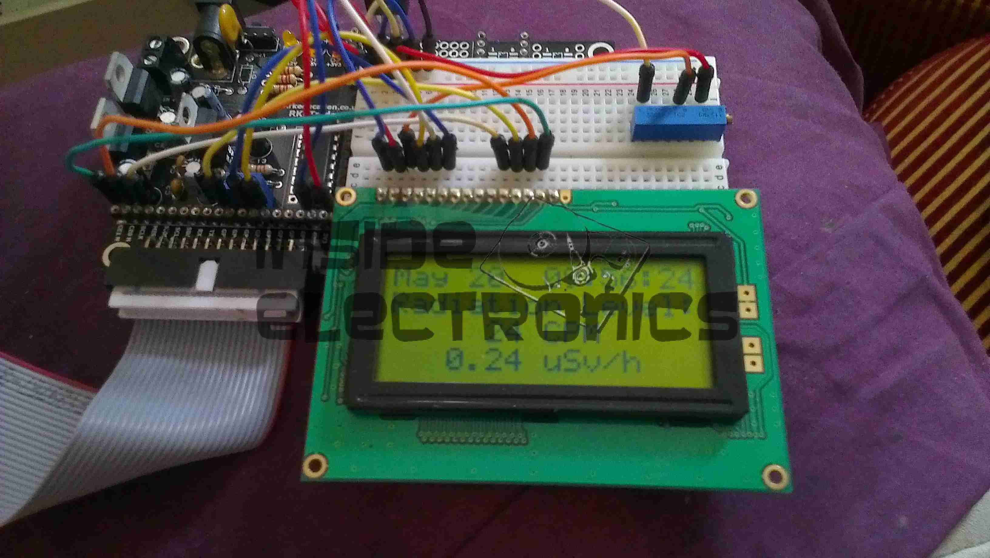
Here’s my latest project with the Pi: interfacing it with the Sparkfun Geiger counter & outputting the resulting data to a character LCD.
The geiger counter is interfaced with it’s USB port, with the random number generator firmware. A Python script reads from the serial port & every minute outputs CPM & µSv/h data to the display.
The Python code is a mash of a few different projects I found online, for different geiger counters & some of my own customisations & code to write the info to the display & convert CPM into µSv/h.
This also writes all the data into a file at /var/log/radlog.txt
The code for this is below:
[snippet id=”1149″]
Info Display
Tip Jar
If you’ve found my content useful, please consider leaving a donation by clicking the Tip Jar below!
All collected funds go towards new content & the costs of keeping the server online.